
VICTOR 1 INGLESE - dutch powered paragliding
14
VICTOR 1 44hp VICTOR 1 PLUS 48hp VICTOR 1 SUPER 54hp This handbook aims to bring to the attention of key technical, functional and maintenance of your motor VICTOR 1. Read carefully the following pages, will be synonymous with safety, reliability and great satisfaction durable. This manual is considered part of the motor VICTOR 1, in case of transfer, will be delivered to the new owner. About this manual lists all of the information available at time of printing. The SIMONINI RACING srl reserves the right to modify or change without notice.
Transcript of VICTOR 1 INGLESE - dutch powered paragliding
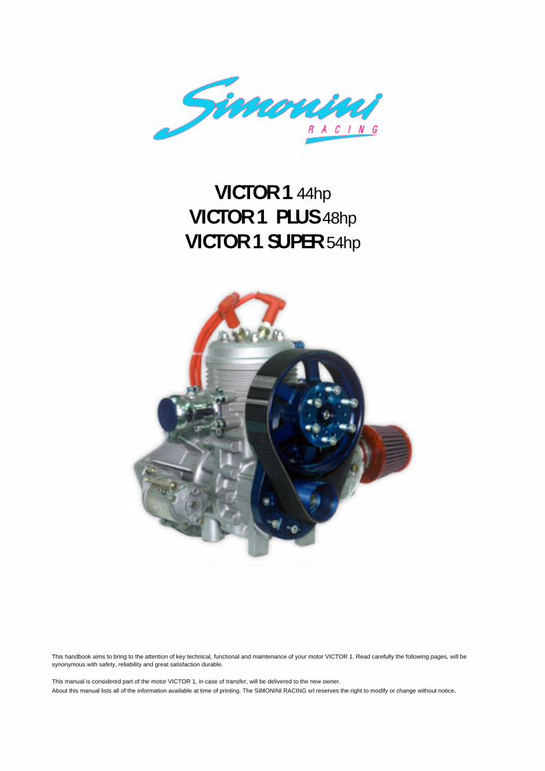
VICTOR 1 44hp
VICTOR 1 PLUS 48hp
VICTOR 1 SUPER 54hp
This handbook aims to bring to the attention of key technical, functional and maintenance of your motor VICTOR 1. Read carefully the following pages, will be
synonymous with safety, reliability and great satisfaction durable.
This manual is considered part of the motor VICTOR 1, in case of transfer, will be delivered to the new owner.
About this manual lists all of the information available at time of printing. The SIMONINI RACING srl reserves the right to modify or change without notice.

TECHNICAL DATA
VICTOR 1 VICTOR 1 PLUS VICTOR 1 SUPER
BORE 80mm 80mm 82mm
STROKE 72mm 76mm 76mm
DISPLACEMENT 362cc 382cc 401cc
COMPRESSION RATUI 9,5/1 9,5/1 9,5/1
WEIGHT ready to fly 32Kg 32Kg 32Kg
CONSUMPTION at 5400RPM 5litres/h 5,6litres/h 5,6litres/h
POWER at 6200RPM 44hp 48hp 54hp
STATIC THRUST Over 120Kg Over 125Kg Over 130Kg
Lamellar intake with Bing 36mm carburetor (Bing 38mm only for Victor 1 Super version)
Aluminum cylinder with ceramic coating magnesium,
Exhaust resonance
Poly-V belt reduction
Double Ducati ignition
Electric starter
Alternator battery charger in flight
Lubrication premix: 2.5% with premium-grade gasoline
3.0% with unleaded fuel
REDUCTION RATIOS AVAILABLE
1:270 crown 183 mm / Pinion 68 mm
1:280 crown 183 mm / Pinion 65 mm
1:300 crown 183 mm / Pinion 61 mm


VICTOR 1/01 KIT ENGINE SCREWS VICTOR 1/51 SET SEEGERS FOR CRANK-CASE
VICTOR 1/02 EXHAUST MANIFOLD AND SPRINGS VICTOR 1/52 COMPLETE SET OF BEARINGS
VICTOR 1/03 COMPLETE SET OF GASKETS VICTOR 1/54 CONNECTING ROD CAGE
VICTOR 1/05 CYLINDER VICTOR 1/55 COMPLETE CRANKSHAFT
VICTOR 1/06 BIG O-RING VICTOR 1/58 COMPLETE IGNITION
VICTOR 1/07 KIT SCREWS FOR CYLINDER VICTOR 1/59 CROWN GEAR FOR STARTER
VICTOR 1/08 CYLINDER HEAD VICTOR 1/60 SPARK-PLUG WIRE
VICTOR 1/10 SET NUTS FOR CYLINDER VICTOR 1/61 SPARK-PLUG BR9ES
VICTOR 1/11 SMALL O-RING VICTOR 1/62 EXHAUST SYSTEM
VICTOR 1/12 SET SCREWS FOR WATER VICTOR 1/63 DOUBLE REDUCTION BEARINGS
VICTOR 1/14 WATER RUBBER MANIFOLD VICTOR 1/64 BIG PULLEY REDUCTION
VICTOR 1/18 CRANK-CASE COVER IGNITION VICTOR 1/65 LITTLE PINION REDUCTION
VICTOR 1/21 BELT FOR WATER PUMP VICTOR 1/66 ALUMINIUM SUPPORT REDUCTION
VICTOR 1/23 DOUBLE PULLEY FOR WATER PUMP VICTOR 1/67 POLY-V BELT
VICTOR 1/24 WATER PUMP VICTOR 1/68 ECCENTRIC PINION
VICTOR 1/28 CRANK-CASE IGNITION VICTOR 1/69 THERMOSTATIC VALVE AND SUPPORT
VICTOR 1/30 RUBBER MANIFOLD VICTOR 1/70 ALUMINIUM PLATE FOR PROP.
VICTOR 1/33 AIR FILTER VICTOR 1/71 BEARINGS SPACER
VICTOR 1/34 BING 54 CARBURETTOR VICTOR 1/72 REDUCTION SEEGER
VICTOR 1/38 REED VALVE VICTOR 1/73 SCREW AND WASHER FOR PINION
VICTOR 1/39 REED VALVE GASKET VICTOR 1/74 SCREW AND WASHER FOR ECCENTRIC
VICTOR 1/41 COIL VICTOR 1/75 RECTIFIER
VICTOR 1/43 CENTRAL CRANK-CASE VICTOR 1/76 EXHAUST GASKET
VICTOR 1/48 ELECTRIC STARTER VICTOR 1P/05 CYLINDER
VICTOR 1/49 WASHER-PRESSURE OUTLET VICTOR 1P/08 CYLINDER HEAD
VICTOR 1/49s COMPLETE PISTON AND RINGS VICTOR 1P/41 CENTRAL CRANK-CASE
VICTOR 1/50 TWO RINGS VICTOR 1P/55 COMPLETE CRANKSHAFT

INSTALLATION
To successfully install the engine with water cooling system, we invite you toobserve this manual. It is a matter of your own and others' safety! In case of doubt or uncertainty, please contact your nearest service SIMONINI center.
COOLING AND CARBURATION
For having a sufficient air flow in front and behind the radiator, do not place any components or accessories near the radiator. The radiating surface should be sized according to the power of your engine, the using and the positioning of the radiator. Normally, for the engine 48 HP, you use a radiator with radiant surface of 700 cm² and 2L. of the total capacity of the cooling system. Ensure that the radiator is exposed to the airflow in an optimal way.
For cooling, use a product with a corrosion inhibitor for light alloys, which is easily finding at the car parts store. A protection for temperatures -15° can be enough.The coolant temperature, leaving the head, at the maximum speed allowed under full load, should not exceed 75°/80°C.
The optimal operating temperature is between 65° and 75°C. Before taking-off, wait until the coolant has reached at least 50°C.
The temperature under spark plug (CHT), in the case of liquid-cooled engines, should not exceed 120°C under full load.
The temperature of exhaust gas (EGT) at cruising speed, must not exceed 580°/600°C, at the maximum speed allowed should not exceed 600°C. Check the reliability of the sensors and instruments!
In the case that the temperature of the exhaust gas (EGT) is lower than 20°C compared to the recommended, you will have to decrease the main jet of 5 numbers at least (e.g. from 180 to 175), then double-check again the temperatures.
In the case that the temperature of the exhaust gas (EGT) is higher than 20°C compared to the recommended above, you will have to work in the reversed way (e.g. from 180 to 185) then double-check again the temperatures.
You can consider the temperatures as reliable when and if the engine reaches the maximum speed allowed for the engine type and the propeller mounted.

Please remember that on the ground, the engine must turn up to 6000/6100 RPM, otherwise while in cruise the maximum is 6400/6500 RPM.
Generally, each two-stroke engine varies the carburetion depending on the outsidetemperature. So in summer time, you can use a main jet of 170/175 and during the winter 180/185. We do suggest to put the needle on the carburetor at the lowest position possible to avoid vibrations due to a minimum too fat. This position must be held even in summer and in winter time.
FUEL SUPPLY SYSTEM
For the implementation of a power plant fuel to the carburetor, please follow the below recommendations:
• put the fuel membrane pump (MIKUNI) 3 or 4cm over the power vacuum on the crankcase.
• The pump must be fitted in horizontal way, with the vacuum fitting grip slightly raked downwards. For a correct running, we suggest to fit the fuel pump by the elastic supports.
• The length of vacuum hose of the pump should not exceed 10/15cm.
• The lowest point of suction in the fuel tank must not exceed 50cm difference in height.
• For an optional gravity functioning of the MIKUNI pneumatic fuel pump, the maximum difference allowed is 70 cm.
• If you want to fit an additional electrical fuel pump to the already present pneumatic one, you will have to create a bypass, with an inserted “no-return” valve on the outlet electric pump. In the case with a double pump, check the attached sheet.
• The maximum pressure reachable by the electric pump should not exceed 0.3 bar (4.35 psi).

INSTALLING THE ENGINE
For proper mounting, we suggest and recommend you to suspend flexibly the drive train in the following ways:
• Mounting the engine straight (with spark plug facing up): usually 4 silent-blocks are enough(our code A22) and they can be installed on the edge of the possible engine mounts between the engine itself and the aircraft frame . We dispose of an Ergal support, complete with silent-blocks that extremely reduces the transmission of vibrations to the aircraft frame.
• Mounting the engine upside down (with spark plug down): please follow the same instructions as the above case. We always recommend the use of the Ergal support, complete with silent-blocks that extremely reduces the transmission of vibrations to the aircraft frame.
• Our water pump has a particular vent-hole, closed by a 6 allen screw, that is used to remove air from the circuit. Without this purge, it might create an air bubble that would prevent the normal circulation of coolant.
• Installation of the exhaust system: the exhaust system provided with our engines is the result of years of research and experimentation. To maintain the standard of performance and to have a long life, we recommend elastically suspend the system using correct silent-blocks. The ball-joint on the exhaust manifold, while assembling, must be lubricated with copper-based grease which can resist at high temperature (800°C).
• For reasons of your own and others' safety, we suggest you to wire exhaust springs to prevent that in case of break, hitting the propeller, they could become bullets.
ELECTRIC SYSTEM
Information usable for all our engines: the motor must be earthed by connecting the aircraft frame by a copper wire. Otherwise you can damage the ignition and some engine components.
The ground must be connected to the starter motor housing support and an additional one between the crankcase and the support of the engine itself.If necessary, check the operation of the mass by its specific instrument, that should indicate a resistance value equal to zero. This operation must be done among the

starter motor support, the fixing points of the engine and the engine mount of the aircraft frame. For starter wires, we suggest you to use a minimum diameter of 8 mm even for the positive and the negative.
When installing the Ducati regulator, used on our engines, the external part of the engine regulator must be earthed by a wire to be screwed to one of the two holes on the regulator; the wire can be directly connected to the negative terminal of the battery or can be connected with the engine mount, being sure you have respected what written before.
The ignition system consists of the following elements: stator, flywheel, pick-up, ignition coils with integrated power module, spark plug wires, spark plugs and spark plug connectors, rectifier/voltage regulator.
The electrical system is by Ducati, with the exception of spark plugs and their wires. The control values are shown on the table attached to this document.
The gap (distance) between the positive electrode and the mass of spark plug, should be between 0.50 and 0.45 mm. With values higher or lower, the proper functioning of the engine can be affected. Spark plugs should be replaced every 150/200 hours.
Our engines use spark plug wires resistive type, silicon insulation. Please try to avoidfriction and/or contact the AT cables with metal surfaces or with high temperatures, which could damage the insulation. To further eliminate the noise induced radio devices, we recommend the using of spark plugs or resistive connectors 5 Kilo Ohm.
During the pre-flight, always check the cables conditions and electrical connectors.
The battery placement must be carried out as far as possible from the engine, subject to the available space; the vapors released (while charging) are corrosive, and they could cause damage to engine components.
To properly connect the voltage regulator, use the following guidelines: the two wires (yellow and yellow-black) coming out from the wheel, must be connected in a stable manner with the two pins marked "GG" on the voltage regulator. Two other pins marked with the letters "RB +" start from the voltage regulator: you can either use one or the other for charging the battery. It is important to have a switch that allows to disconnect when the engine is off. Never disconnect for any reason, the battery charging cable while the engine is running.
FIRST START
Every engine we produce, after having been assembled, is subjected to a dynamic testing. We put them on a special test stand, fit a suitable propeller and start it. This operation requires 4/6 hours at variable speeds, monitoring the temperatures. At the same time, we run an optimal adjustment of the carburetor. When installation your engine, you do only have to follow with good attention all the given suggestions we have done to take full advantages that all Simonini engines can give.
When connecting the throttle cable, pay special attention to the sequence mounting the pin, its claps and the plastic collar, where the spring presses. This sequence must be followed to avoid problems.
After having done the above, please check the air screw, which must be unscrewed from totally closed position of 1-1,5 rounds. When finished, you can proceed with the start.
With the throttle fully closed and the inserted choke you can try to make the starter: do not hold the starter for more than 5 seconds. Once it is started, wait 4/5 seconds and then gradually remove the choke until the engine turns on a regular basis.
Do not use the gas pedal when you try to start a cold engine: you could only choke it!
Once the engine gradually warmed up (1-2 minutes), accelerate and stabilize the gas at about 3800/4000 rpm.
At this point, you can reduce the engine speed to the minimum, which must be set at 2100/2200 rpm. If not, turn the idle screw and adjust properly.
If you have followed all the directions above, the result is an engine without any starting problem, with a regular smooth idle and very stable.
At the end of this phase, once the engine has reached the minimum working temperature (50°C) you can make a flight test, checking the maximum temperatures on the ground for 10-15 seconds maximum: EGT must not exceed 600°C at the maximum speed allowed, according to the engine type.
If you install a propeller that cannot achieve a maximum speed at ground, you will have to control the main jet, increasing its section up to the point where the engine

reaches higher rpm.
Replacing the propeller the carburetion changes. If the propeller is overloaded and the engine speed does not reach the previously established, we must put a bigger jet. However, we recommend the use of propellers already experienced by us as a 2 blades wooden propeller by GT Propeller, cm 164.
LUBRICATION
To prepare the mixture of oil and gasoline, we recommend using a semi-synthetic lubricant, which exceed the API TC, JASO FC, (for example, BARDHAL Plus VBA or API Mixoilsint).
The oil percentage to be used in our engines with liquid cooling, varies from the oil type used: 3% if you use unleaded petrol (unleaded) 2% if you use leaded gasoline (premium gasoline).
To prepare it appropriately, we recommend to use clean tanks, put first the oil and then enter the correct quantity of fuel in the tank. Later, with the tank closed and holding it firmly in your hands, flip it over repeatedly allowing good mixing of the oil and fuel.
TORQUE AND LIMIT
- Screw M12 Flywheel power: 70Nm. - Screw M 8 Water pump casing: 22Nm. - Screws M 8 Stator ignition and starter motor: 23Nm. - Screw M10 Cylinder screw: 60Nm. - Screw M 8 Head: 23Nm.
Piston with new cylinder when assembling: 0.06 to 0.07 mm Wear limit between the piston and its cylinder: 0.12 mmMaximum cylinder taper: 0.04 mm Maximum ovalization: 0.04 mm The measurement of the piston is referred to 12/13 mm from the base of the mantle
Piston rings: the installation 0.35 mm, wear limit 0.40 mm.

Crankshaft: maximum off-center of a new crankshaft when assembling: 0.01 mm maximum off-center allowed when used: 0.04 mm
Axial rod movement: wear limit 0.04 mm.
ROUTINE MAINTENANCE
Every 50 hours: check spark plug gap and possible recovery to the correct value:from 0.4 to 0.45 mm.
Every 200 hours: replace the spark plugs, control the engine torque mount screws. After the first 400 hours: disassemble the heating units and control the tolerance. If the readings data are 80% of the wear limit, replace the components with highvalue. Change the reed valves petals.
The TBO of the engine is done 500/600 hours, depending on usage. We suggest toremove the engine and send it to the factory or at a qualified service center to serve a general recovery. Our engines are built with the finest Italian metals on the market. These basic conditions are in particular so that many do not wear out, reducing by more than 50% the cost of repairing the engine.
BELT TENSIONWARNING: THE ENGINE HAS TO BE OFF AND COLD
During operation, the belt is subjected to traction and wear, it follows that an extension could lead to his slip on the pulleys as to reduce the overall performance of the engine. To restore the proper tension, loosen the screw M8 (No. 77) on the foot that shuts the engine and the cam pulley with a torque wrench to turn the screw counter-clockwise M12 (No. 74) by a force of 2.4 kgm, tighten the M8 (No. 77).
PARTS AND TOOLS REQUIRED
To have the possibility to customize the engine and then adapt it to different needs and use patterns, the SIMONINI offers a number of components required:
DRIVING PULLEYIn three different diameters (61/65/68) as well as providing the proper ratio, can be used to soften or make more rapid rise in the engine speed or to move, while maintaining the propeller revolutions, any points on the curve couple who do not

meet your needs at a specified "range" of use, such as in speed. Code VICTOR 1/64 61mm. Code VICTOR 1/64 65mm. Code VICTOR 1/64 68mm.
PROPELLERSWe have a two-bladed wooden propeller type of door, drawer or pushing Code E04 cm. 159
TOOLS FOR MAINTENANCETo facilitate maintenance tools have been produced two distinct acts of extraction of the drive pulley and flywheel power Code U03 Pinion Puller Code U05 magnetic wheel extractor

REQUEST FOR REPAIR OR REPLACEMENT OF WARRANTED
CAUTION The warranty is valid 'OF 12 MONTHS FROM DATE OF PURCHASE AND' extended to all the details that make up the engine (EXCLUDING SPECIAL TO WEAR TO CARRY NIKASIL the cylinder, piston skirt and drive belts). THE WARRANTY IS VOIDED IF THE ENGINE HAS been tampered with or have been superseded WITH OTHER PARTS NOT ORIGINAL OR NOT APPROVED BY U.S.. I WILL BE COVERED PARTS REPLACED UNDER WARRANTY FOR 12 MONTHS FROM DATE OF SHIPMENT. FOR ANY CHANGE IN THE SPECIAL WARRANTY IS DEFECTIVE MUST BE SENT TO: SIMONINI RACING IN PORTO FRANCO SRL. CHANGE REQUEST FORM • NAME • RESIDENCE • NUMBER OF MOTOR • DATE OF FIRST START • HOURS OF OPERATION • ANY PREVIOUS REPAIRS • ANY REPAIR THE LAST HOURS OF OPERATION • SETTING CARB • DESCRIPTION OF 'ADVERSE FOUND
We appreciate the trust given to us, we remind you that the staff of SIMONINI RACING srl will be at your disposal for any questions.
SIMONINI RACING SRL Via Marano For 4303, Loc San Dalmazio - 41028 Serramazzoni (Mo)
Tel 0536/953005 Fax 0536/953006. Http: www.Simonini-flying.com E-mail: [email protected]