VicRoads Supplement to AGRD Part 4a - Unsignalised and …/media/files/technical-documents... ·...
16
VicRoads Supplement to Austroads Guide to Road Design – Part 4A Rev. 2.0 - July 2011 Part 4A – Page 1 VicRoads Supplement to the Austroads Guide to Road Design Part 4A - Signalised & Unsignalised Intersections NOTE: This VicRoads Supplement must be read in conjunction with the Austroads Guide to Road Design. Reference to any VicRoads or other documentation refers to the latest version as publicly available on VicRoads website or other external source.
Transcript of VicRoads Supplement to AGRD Part 4a - Unsignalised and …/media/files/technical-documents... ·...
VicRoads Supplement to Austroads Guide to Road Design – Part 4A
Rev. 2.0 - July 2011 Part 4A – Page 1
VicRoads Supplement
to the Austroads Guide to Road Design
Part 4A - Signalised & Unsignalised Intersections
NOTE:
This VicRoads Supplement must be read in conjunction with the Austroads Guide to Road Design.
Reference to any VicRoads or other documentation refers to the latest version as publicly available on VicRoads website or other external source.
VicRoads Supplement to Austroads Guide to Road Design – Part 4A
Rev. 2.0 - July 2011 Part 4A – Page 2
VicRoads Supplement to the Austroads Guide to Road Design Updates Record
Part 4A - Signalised & Unsignalised Intersections
Rev. No. Date Released
Section/s Update
Description of Revision Authorised By
Rev 1.0
July 2010
First Edition Development of Supplement ED – Network & Asset Planning
Rev. 1.1
Sept 2010
Minor changes to text, references and layouts.
Principal Advisor – Road Design, Traffic & Standards
Rev. 2.0
July 2011
Section 3.3
Section 4.13
Section 7.6.5
Pedestrian Sight Distance
Reference to wide medians
Rural Wide Median Treatments
Insert Figure V7.3
Principal Advisor – Road Design, Traffic & Standards
COPYRIGHT © 2010 ROADS CORPORATION.
This document is copyright. No part of it can be used, amended or reproduced by any process without written permission of the Principal Road Design Engineer of the Roads Corporation Victoria.
ISBN 978-0-7311-9154-3
VRPIN 02666
This VicRoads Supplement has been developed by VicRoads Technical Consulting and authorised by the Executive Director – Network and Asset Planning.
The VicRoads Supplement to the Austroads Guide to Road Design provides additional information, clarification or jurisdiction specific design information and procedures which may be used on works financed wholly or in part by funds from VicRoads beyond that outlined in the Austroads Guide to Road Design guides.
Although this publication is believed to be correct at the time of printing, VicRoads does not accept responsibility for any consequences arising from the information contained in it. People using the information should apply, and rely upon, their own skill and judgement to the particular issue which they are considering. The procedures set out will be amended from time to time as found necessary.
VicRoads Supplement to Austroads Guide to Road Design – Part 4A
Rev. 2.0 - July 2011 Part 4A – Page 3
References AGRD – Austroads Guide to Road Design
AGTM – Austroads Guide to Traffic Management
GTEP – Guide to Traffic Engineering Practice (superseded)
VRD/RDG – VicRoads Road Design Guidelines (superseded)
Austroads (2005). Guide to Traffic Engineering Practice – Part 5: Intersections at Grade (Superseded).
Austroads (2009). Austroads Guide to Road Design – Part 3: Geometric Design.
Austroads (2009). Austroads Guide to Traffic Management – Part 3: Traffic Studies and Analysis.
VicRoads Traffic Engineering Manual Volume 1 – Traffic Management
VicRoads Traffic Engineering Manual Volume 2 – Signs and Markings
VicRoads Supplement to Austroads Guide to Road Design – Part 4A
Rev. 2.0 - July 2011 Part 4A – Page 4
VicRoads Supplement to Austroads Guide to Road Design – Part 4A
Rev. 2.0 - July 2011 Part 4A – Page 5
1.0 Introduction VicRoads has no supplementary comments for this section.
2.0 Layout Design Process
2.1 Design Process VicRoads has no supplementary comments for this section.
2.2 Alignment of Intersection Approaches Clarification 2.2.1 Horizontal Alignment
Departure tapers are not supported as they do not provide sufficient length for vehicles to accelerate in and select appropriate gaps in traffic to merge however encourages this movement. Therefore design between points C and D in AGRD Part 4A, Figure 2.3 are not supported.
2.2.4 Superelevation at or near Intersections
Additional Information MAXIMUM EFFECTIVE ADVERSE CROSSFALL
The maximum ‘effective adverse crossfall’ for turning movements at intersections can be determined using vector diagrams. The procedure is explained in the examples which follow.
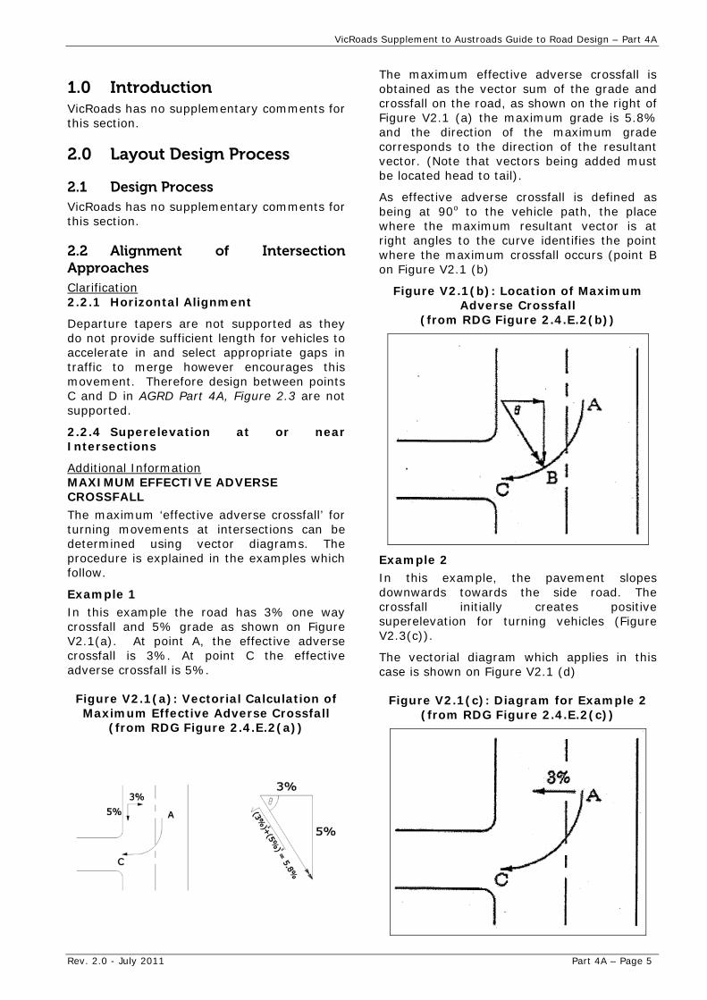
Example 1 In this example the road has 3% one way crossfall and 5% grade as shown on Figure V2.1(a). At point A, the effective adverse crossfall is 3%. At point C the effective adverse crossfall is 5%.
Figure V2.1(a): Vectorial Calculation of Maximum Effective Adverse Crossfall
(from RDG Figure 2.4.E.2(a))
The maximum effective adverse crossfall is obtained as the vector sum of the grade and crossfall on the road, as shown on the right of Figure V2.1 (a) the maximum grade is 5.8% and the direction of the maximum grade corresponds to the direction of the resultant vector. (Note that vectors being added must be located head to tail).
As effective adverse crossfall is defined as being at 90o to the vehicle path, the place where the maximum resultant vector is at right angles to the curve identifies the point where the maximum crossfall occurs (point B on Figure V2.1 (b)
Figure V2.1(b): Location of Maximum Adverse Crossfall
(from RDG Figure 2.4.E.2(b))
Example 2 In this example, the pavement slopes downwards towards the side road. The crossfall initially creates positive superelevation for turning vehicles (Figure V2.3(c)).
The vectorial diagram which applies in this case is shown on Figure V2.1 (d)
Figure V2.1(c): Diagram for Example 2 (from RDG Figure 2.4.E.2(c))
VicRoads Supplement to Austroads Guide to Road Design – Part 4A
Rev. 2.0 - July 2011 Part 4A – Page 6
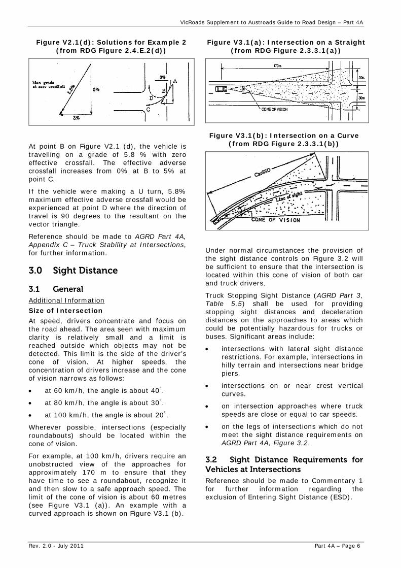
Figure V2.1(d): Solutions for Example 2 (from RDG Figure 2.4.E.2(d))
At point B on Figure V2.1 (d), the vehicle is travelling on a grade of 5.8 % with zero effective crossfall. The effective adverse crossfall increases from 0% at B to 5% at point C.
If the vehicle were making a U turn, 5.8% maximum effective adverse crossfall would be experienced at point D where the direction of travel is 90 degrees to the resultant on the vector triangle.
Reference should be made to AGRD Part 4A, Appendix C – Truck Stability at Intersections, for further information.
3.0 Sight Distance
3.1 General Additional Information
Size of Intersection
At speed, drivers concentrate and focus on the road ahead. The area seen with maximum clarity is relatively small and a limit is reached outside which objects may not be detected. This limit is the side of the driver’s cone of vision. At higher speeds, the concentration of drivers increase and the cone of vision narrows as follows:
at 60 km/h, the angle is about 40°.
at 80 km/h, the angle is about 30°.
at 100 km/h, the angle is about 20°.
Wherever possible, intersections (especially roundabouts) should be located within the cone of vision.
For example, at 100 km/h, drivers require an unobstructed view of the approaches for approximately 170 m to ensure that they have time to see a roundabout, recognize it and then slow to a safe approach speed. The limit of the cone of vision is about 60 metres (see Figure V3.1 (a)). An example with a curved approach is shown on Figure V3.1 (b).
Figure V3.1(a): Intersection on a Straight (from RDG Figure 2.3.3.1(a))
Figure V3.1(b): Intersection on a Curve (from RDG Figure 2.3.3.1(b))
Under normal circumstances the provision of the sight distance controls on Figure 3.2 will be sufficient to ensure that the intersection is located within this cone of vision of both car and truck drivers.
Truck Stopping Sight Distance (AGRD Part 3, Table 5.5) shall be used for providing stopping sight distances and deceleration distances on the approaches to areas which could be potentially hazardous for trucks or buses. Significant areas include:
intersections with lateral sight distance restrictions. For example, intersections in hilly terrain and intersections near bridge piers.
intersections on or near crest vertical curves.
on intersection approaches where truck speeds are close or equal to car speeds.
on the legs of intersections which do not meet the sight distance requirements on AGRD Part 4A, Figure 3.2.
3.2 Sight Distance Requirements for Vehicles at Intersections Reference should be made to Commentary 1 for further information regarding the exclusion of Entering Sight Distance (ESD).
VicRoads Supplement to Austroads Guide to Road Design – Part 4A
Rev. 2.0 - July 2011 Part 4A – Page 7
3.2.1 Approach Sight Distance (ASD)
Additional Information
Approach Sight Distance also applies to:
merge areas on all roads, and
start and end of overtaking lanes
fords and floodways
pedestrian movements
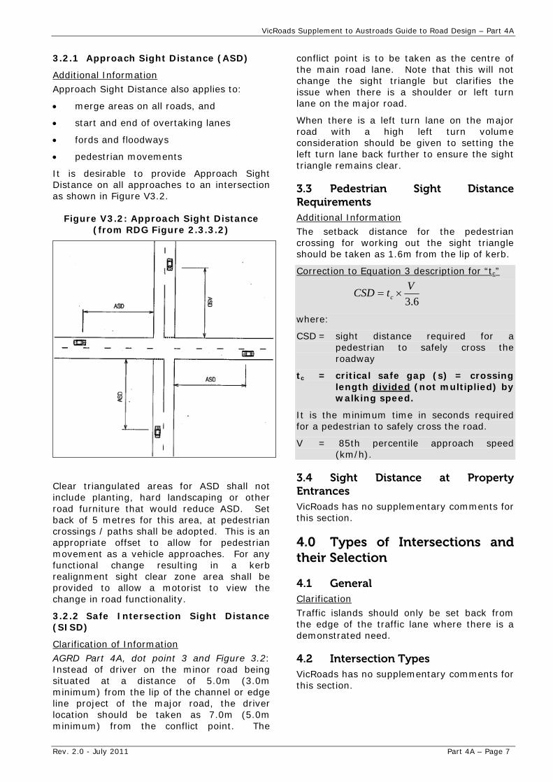
It is desirable to provide Approach Sight Distance on all approaches to an intersection as shown in Figure V3.2.
Figure V3.2: Approach Sight Distance (from RDG Figure 2.3.3.2)
Clear triangulated areas for ASD shall not include planting, hard landscaping or other road furniture that would reduce ASD. Set back of 5 metres for this area, at pedestrian crossings / paths shall be adopted. This is an appropriate offset to allow for pedestrian movement as a vehicle approaches. For any functional change resulting in a kerb realignment sight clear zone area shall be provided to allow a motorist to view the change in road functionality.
3.2.2 Safe Intersection Sight Distance (SISD)
Clarification of Information
AGRD Part 4A, dot point 3 and Figure 3.2: Instead of driver on the minor road being situated at a distance of 5.0m (3.0m minimum) from the lip of the channel or edge line project of the major road, the driver location should be taken as 7.0m (5.0m minimum) from the conflict point. The
conflict point is to be taken as the centre of the main road lane. Note that this will not change the sight triangle but clarifies the issue when there is a shoulder or left turn lane on the major road.
When there is a left turn lane on the major road with a high left turn volume consideration should be given to setting the left turn lane back further to ensure the sight triangle remains clear.
3.3 Pedestrian Sight Distance Requirements Additional Information
The setback distance for the pedestrian crossing for working out the sight triangle should be taken as 1.6m from the lip of kerb.
Correction to Equation 3 description for “tc”
6.3
VtCSD c
where:
CSD = sight distance required for a pedestrian to safely cross the roadway
tc = critical safe gap (s) = crossing length divided (not multiplied) by walking speed.
It is the minimum time in seconds required for a pedestrian to safely cross the road.
V = 85th percentile approach speed (km/h).
3.4 Sight Distance at Property Entrances VicRoads has no supplementary comments for this section.
4.0 Types of Intersections and their Selection
4.1 General Clarification
Traffic islands should only be set back from the edge of the traffic lane where there is a demonstrated need.
4.2 Intersection Types VicRoads has no supplementary comments for this section.
VicRoads Supplement to Austroads Guide to Road Design – Part 4A
Rev. 2.0 - July 2011 Part 4A – Page 8
4.3 Types of Turn Treatments VicRoads has no supplementary comments for this section.
4.4 Intersection Selection
4.4.1 General Considerations
VicRoads should be consulted for appropriate crash rates.
Refer to AGRD Part 4A, Appendix C for advice regarding truck stability.
4.4.2 Traffic Management Considerations
Correction to Formula
The Formula shown is incorrect. The square root sign should extend over (V1 x V2) not just V1.
4.5 Basic Turn (Type BA) Treatments
4.5.1 Rural Basic (BA) Turn Treatments
Correction to AGRD Part 4A, Figure 4.1
The holding/stop line shall be located in accordance with VicRoads Traffic Engineering Manual (TEM) Volume 2, Chapter 17 in lieu of that shown in the Austroads document.
4.5.2 Urban Basic (BA) Turn Treatments
Correction to AGRD Part 4A, Figure 4.2
The holding/stop line shall be located in accordance with VicRoads TEM Volume 2, Chapter 17 in lieu of that shown in the Austroads document.
4.5.3 Basic Right–turn Treatment – Multi-lane Undivided Road
Correction to AGRD Part 4A, Figure 4.3
The holding/stop line shall be located in accordance with VicRoads TEM Volume 2, Chapter 17 in lieu of that shown in the Austroads document.
4.6 Auxiliary Lane Turn (Type AU) Treatments Additional Information
Widths of Auxiliary (turn) lanes should be as adopted for through lanes. However, when carriageway widths are restricted, the turn lane widths should be reduced before through lane widths are reduced. A width of 2.8m may be acceptable in constrained situations.
Lane widths are discussed in more detail in Austroads Guide to Traffic Management (AGTM) Part 3.
Correction to AGRD Part 4A, Figure 4.4
The holding/stop line shall be located in accordance with VicRoads TEM Volume 2, Chapter 17 in lieu of that shown in the Austroads document.
4.6.1 Rural Auxiliary Lane (AU) Turn Treatments
Clarification
When considering AUL treatments, especially on a curve, consideration should be given to the impact of left turners on the sight lines. High volume left turn situations may require an alternative treatment to AULs. AULs are still considered a viable treatment in Victoria where guidelines are met.
Correction to AGRD Part 4A, Figure 4.5
The holding/stop line shall be located in accordance with VicRoads TEM Volume 2, Chapter 17 in lieu of that shown in the Austroads document.
Correction to AGRD Part 4A, Figure 4.6
The holding/stop line shall be located in accordance with VicRoads TEM Volume 2, Chapter 17 in lieu of that shown in the Austroads document.
4.7 Channelised Turn (Type CH) Treatments Correction to AGRD Part 4A, Figure 4.7
The holding/stop line shall be located in accordance with VicRoads TEM Volume 2, Chapter 17 in lieu of that shown in the Austroads document.
4.8 Warrants for BA, AU and CH Turn Treatments Clarification of last dot point
Qm is to equal the sum of the volume in all through lanes, not just the lane closest to the turn lane.
When using AGRD Part 4A, Figure 4.9 to determine appropriate turn treatments, the use of an AUR (Auxiliary Right Turn) is still permitted in Victoria when a CHR(S) is warranted. VicRoads should be consulted when considering the use of a CHR(S) versus a AUR treatment. Details of an AUR treatment are provided in AGRD Part 4A, Sections 7.5.2 and 7.7.2.
4.9 Intersection Treatments – Rural Divided Roads
4.9.2 Offset Right-turn Lanes
Offset Right turn lanes are not common practice in Victoria.
VicRoads Supplement to Austroads Guide to Road Design – Part 4A
4.10 Intersection Treatments – Urban Divided Roads
5.0 Auxiliary Lanes
5.1 General 4.10.1 Basic Median Opening VicRoads has no supplementary comments for this section. Correction to AGRD Part 4A, Figure 4.13
The holding/stop line shall be located in accordance with VicRoads TEM Volume 2, Chapter 17 in lieu of that shown in the Austroads document.
5.2 Determining the Need for Auxiliary Lanes VicRoads has no supplementary comments for this section. 4.10.2 Urban Offset Right-turn Lanes
Offset Right turn lanes are not common practice in Victoria. 5.3 Deceleration Turn Lane Length
5.3.1 Components of Deceleration Turn Lanes 4.11 Staggered T-intersections
4.11.1 Rural Staggered T-intersection Treatments
It is desirable that Deceleration plus Storage Length be provided, but it should be noted that sometimes this distance can be unreasonably long and there may be constraints that prohibit providing this length. Deceleration length must be the minimum length provided in all situations.
Correction to AGRD Part 4A, Figure 4.17
The holding/stop line shall be located in accordance with VicRoads TEM Volume 2, Chapter 17 in lieu of that shown in the Austroads document.
5.4 Determination of Acceleration Lane Length for Cars
4.12 Seagull Treatments VicRoads has no supplementary comments for this section. VicRoads has no supplementary comments for
this section.
4.13 Wide Median Treatment 5.5 Acceleration Lane Design for Trucks
Refer to AGRD Part 4A, Section 7.65 and associated supplements for further detail on the design of rural wide median treatments. VicRoads has no supplementary comments for
this section. 4.14 Channelised Intersections with Right-turn Restrictions 5.6 Auxiliary through Lane Design
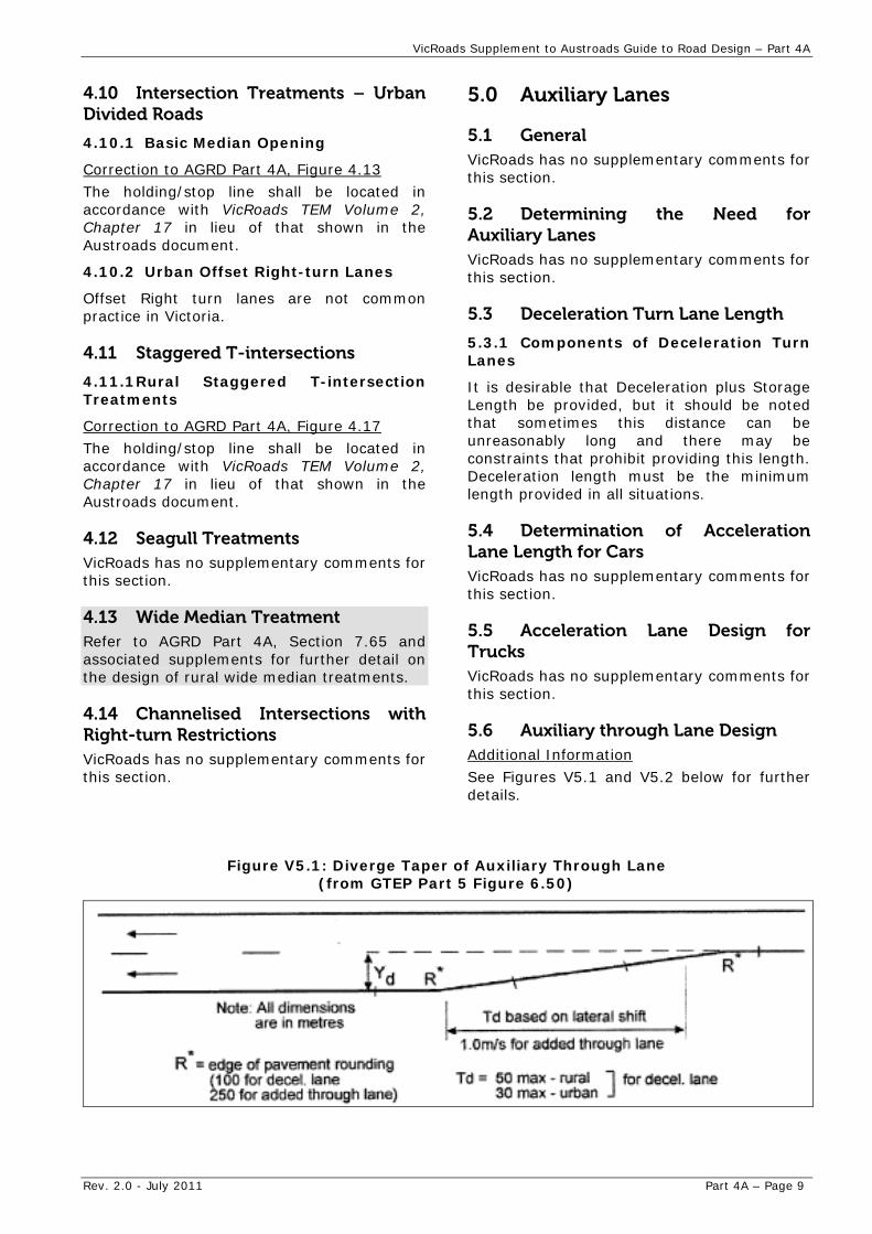
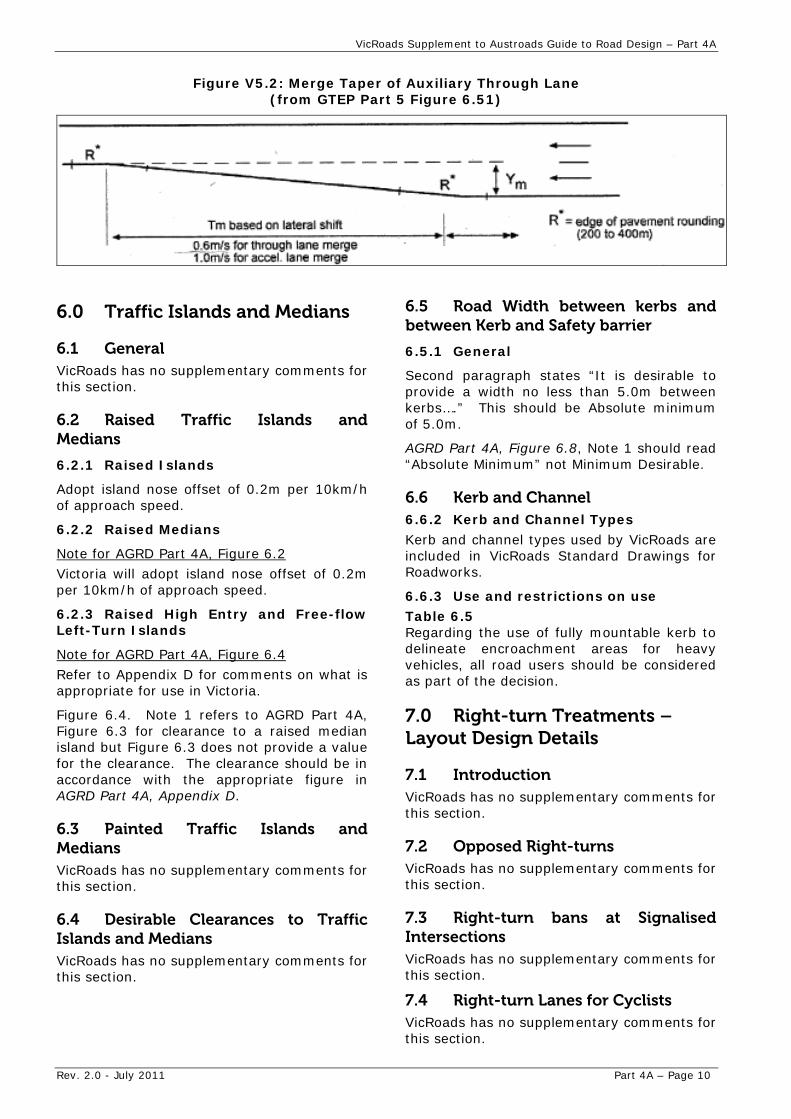
Additional Information VicRoads has no supplementary comments for this section. See Figures V5.1 and V5.2 below for further
details.
Figure V5.1: Diverge Taper of Auxiliary Through Lane (from GTEP Part 5 Figure 6.50)
Rev. 2.0 - July 2011 Part 4A – Page 9
VicRoads Supplement to Austroads Guide to Road Design – Part 4A
Rev. 2.0 - July 2011 Part 4A – Page 10
Figure V5.2: Merge Taper of Auxiliary Through Lane (from GTEP Part 5 Figure 6.51)
6.0 Traffic Islands and Medians
6.1 General VicRoads has no supplementary comments for this section.
6.2 Raised Traffic Islands and Medians
6.2.1 Raised Islands
Adopt island nose offset of 0.2m per 10km/h of approach speed.
6.2.2 Raised Medians
Note for AGRD Part 4A, Figure 6.2
Victoria will adopt island nose offset of 0.2m per 10km/h of approach speed.
6.2.3 Raised High Entry and Free-flow Left-Turn Islands
Note for AGRD Part 4A, Figure 6.4
Refer to Appendix D for comments on what is appropriate for use in Victoria.
Figure 6.4. Note 1 refers to AGRD Part 4A, Figure 6.3 for clearance to a raised median island but Figure 6.3 does not provide a value for the clearance. The clearance should be in accordance with the appropriate figure in AGRD Part 4A, Appendix D.
6.3 Painted Traffic Islands and Medians VicRoads has no supplementary comments for this section.
6.4 Desirable Clearances to Traffic Islands and Medians VicRoads has no supplementary comments for this section.
6.5 Road Width between kerbs and between Kerb and Safety barrier
6.5.1 General
Second paragraph states “It is desirable to provide a width no less than 5.0m between kerbs….” This should be Absolute minimum of 5.0m.
AGRD Part 4A, Figure 6.8, Note 1 should read “Absolute Minimum” not Minimum Desirable.
6.6 Kerb and Channel 6.6.2 Kerb and Channel Types
Kerb and channel types used by VicRoads are included in VicRoads Standard Drawings for Roadworks.
6.6.3 Use and restrictions on use Table 6.5 Regarding the use of fully mountable kerb to delineate encroachment areas for heavy vehicles, all road users should be considered as part of the decision.
7.0 Right-turn Treatments – Layout Design Details
7.1 Introduction VicRoads has no supplementary comments for this section.
7.2 Opposed Right-turns VicRoads has no supplementary comments for this section.
7.3 Right-turn bans at Signalised Intersections VicRoads has no supplementary comments for this section.
7.4 Right-turn Lanes for Cyclists VicRoads has no supplementary comments for this section.
VicRoads Supplement to Austroads Guide to Road Design – Part 4A
Rev. 2.0 - July 2011 Part 4A – Page 11
7.5 Rural Right-turn Treatment – Undivided Roads
7.5.1 Rural Basic Right-turn (BAR) Treatment
Correction to AGRD Part 4A, Figure 7.5
The holding/stop line shall be located in accordance with VicRoads TEM Volume 2, Chapter 17 in lieu of that shown in the Austroads document.
7.5.2 Rural Channelised T-Junction – Short Lane Type CHR(S) (from GTEP Part 5)
Barrier line to be used in accordance with the VicRoads TEM Volume 2, Chapter 16.
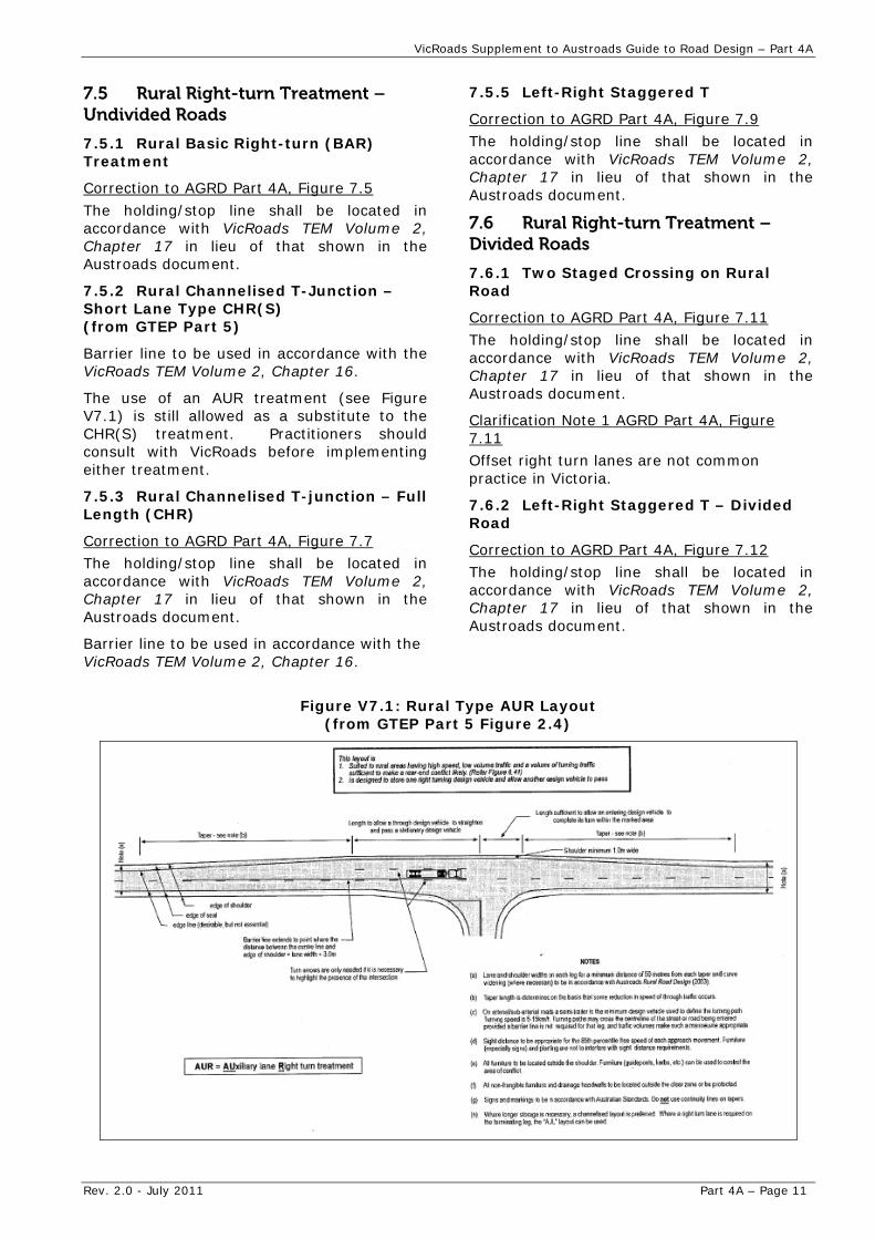
The use of an AUR treatment (see Figure V7.1) is still allowed as a substitute to the CHR(S) treatment. Practitioners should consult with VicRoads before implementing either treatment.
7.5.3 Rural Channelised T-junction – Full Length (CHR)
Correction to AGRD Part 4A, Figure 7.7
The holding/stop line shall be located in accordance with VicRoads TEM Volume 2, Chapter 17 in lieu of that shown in the Austroads document.
Barrier line to be used in accordance with the VicRoads TEM Volume 2, Chapter 16.
7.5.5 Left-Right Staggered T
Correction to AGRD Part 4A, Figure 7.9
The holding/stop line shall be located in accordance with VicRoads TEM Volume 2, Chapter 17 in lieu of that shown in the Austroads document.
7.6 Rural Right-turn Treatment – Divided Roads
7.6.1 Two Staged Crossing on Rural Road
Correction to AGRD Part 4A, Figure 7.11
The holding/stop line shall be located in accordance with VicRoads TEM Volume 2, Chapter 17 in lieu of that shown in the Austroads document.
Clarification Note 1 AGRD Part 4A, Figure 7.11
Offset right turn lanes are not common practice in Victoria.
7.6.2 Left-Right Staggered T – Divided Road
Correction to AGRD Part 4A, Figure 7.12
The holding/stop line shall be located in accordance with VicRoads TEM Volume 2, Chapter 17 in lieu of that shown in the Austroads document.
Figure V7.1: Rural Type AUR Layout (from GTEP Part 5 Figure 2.4)
VicRoads Supplement to Austroads Guide to Road Design – Part 4A
Rev. 2.0 - July 2011 Part 4A – Page 12
7.6.3 Back-to-back Right Turns on a Divided Road
Correction to AGRD Part 4A, Figure 7.13
The holding/stop line shall be located in accordance with VicRoads TEM Volume 2, Chapter 17 in lieu of that shown in the Austroads document.
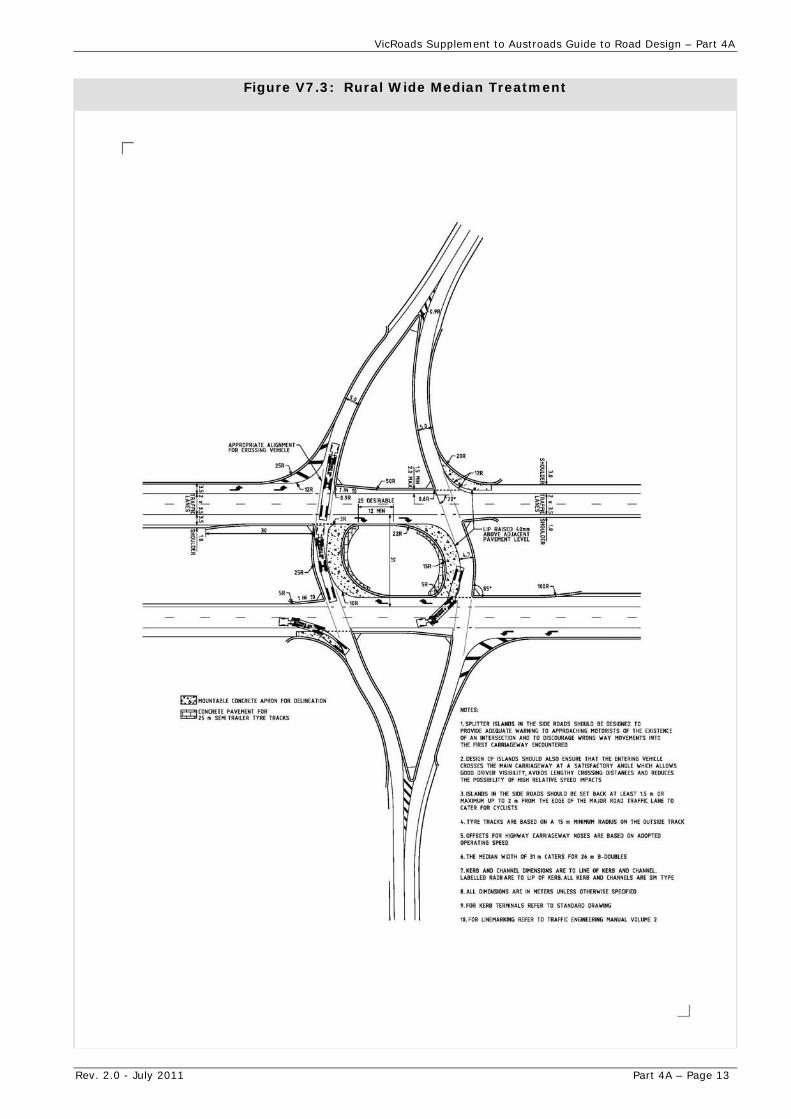
7.6.5 Rural Wide Median Treatment
Additional Information
Refer to Figure V7.3 for additional information regarding development of an appropriate design for rural wide median treatments.
7.7 Urban Right-turn Treatment – Undivided Roads
7.7.2 Urban Channelised T-Junction – Short Lane Type CHR(S) (from GTEP Part 5)
Correction to AGRD Part 4A, Figure 7.18
The holding/stop line shall be located in accordance with VicRoads TEM Volume 2,
Chapter 17 in lieu of that shown in the Austroads document.
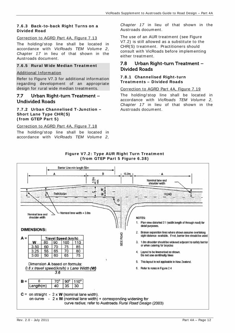
The use of an AUR treatment (see Figure V7.2) is still allowed as a substitute to the CHR(S) treatment. Practitioners should consult with VicRoads before implementing either treatment.
7.8 Urban Right-turn Treatment – Divided Roads
7.8.1 Channelised Right-turn Treatments – Divided Roads
Correction to AGRD Part 4A, Figure 7.19
The holding/stop line shall be located in accordance with VicRoads TEM Volume 2, Chapter 17 in lieu of that shown in the Austroads document.
Figure V7.2: Type AUR Right Turn Treatment (from GTEP Part 5 Figure 6.38)
VicRoads Supplement to Austroads Guide to Road Design – Part 4A
Rev. 2.0 - July 2011 Part 4A – Page 13
Figure V7.3: Rural Wide Median Treatment
VicRoads Supplement to Austroads Guide to Road Design – Part 4A
Rev. 2.0 - July 2011 Part 4A – Page 14
8.0 Left-turn Treatments
8.1 General VicRoads has no supplementary comments for this section.
8.2 Rural Left-turn Treatments
8.2.1 Rural Basic Left-turn (BAL) Treatment
Clarification of Sb value
The holding/stop line shall be located in accordance with VicRoads TEM Volume 2, Chapter 17 in lieu of that shown in the Austroads document.
8.2.2 Rural Auxiliary Left-turn Treatment – Short Turn Lane [AUL(S)] on the Major Road
Correction to AGRD Part 4A, Figure 8.3
The holding/stop line shall be located in accordance with VicRoads TEM Volume 2, Chapter 17 in lieu of that shown in the Austroads document.
‘F’ shall be defined as ‘Formation/carriageway widening (m)’. Refer to AGRD Part 4A, Figure 8.2 for location of ‘F’.
8.2.3 Rural Auxiliary Left-turn Lane (AUL) Treatment
Correction to AGRD Part 4A, Figure 8.4
The holding/stop line shall be located in accordance with VicRoads TEM Volume 2, Chapter 17 in lieu of that shown in the Austroads document.
8.2.4 Rural Channelised Left-turn (CHL) Treatments with High Entry Angle
Alternative CHL layouts which are provided in AGRD Part 4A, Appendix D with guidance of use provided in this document.
Linemarking shown around the island is not something that would be done to that extent in Victoria. See comments regarding figures in AGRD Part 4A, Appendix D for further guidance.
Correction to AGRD Part 4A, Figure 8.5
The holding/stop line shall be located in accordance with VicRoads TEM Volume 2, Chapter 17 in lieu of that shown in the Austroads document.
8.2.5 Rural Channelised Left-turn (CHL) Treatment with Acceleration Lane
Alternative CHL layouts with acceleration lanes which are provided in AGRD Part 4A, Appendix D with guidance of use provided in this document.
Linemarking shown around the island is not something that would be done to that extent in Victoria. See comments regarding figures in AGRD Part 4A, Appendix D for further guidance.
Correction to AGRD Part 4A, Figure 8.6
The holding/stop line shall be located in accordance with VicRoads TEM Volume 2, Chapter 17 in lieu of that shown in the Austroads document.
8.3 Urban Left-turn Treatments
8.3.1 Urban basic Left-turn Treatment
Correction to AGRD Part 4A, Figure 8.8
The holding/stop line shall be located in accordance with VicRoads TEM Volume 2, Chapter 17 in lieu of that shown in the Austroads document.
8.3.2 Urban Auxiliary Left-turn Treatment – Short Turn Lane [AUL(S)] Major Road
Correction to AGRD Part 4A, Figure 8.10
The holding/stop line shall be located in accordance with VicRoads TEM Volume 2, Chapter 17 in lieu of that shown in the Austroads document.
8.3.3 Urban Auxiliary Left-turn (AUL) Treatment on the Major Road
Correction to text
Reference to AGRD Part 4A, Figure 8.1 should be Figure 8.11.
Correction to AGRD Part 4A, Figure 8.11
The holding/stop line shall be located in accordance with VicRoads TEM Volume 2, Chapter 17 in lieu of that shown in the Austroads document.
8.3.4 Urban Channelised Left-turn (CHL) Treatment with High Entry Angle
Refer to AGRD Part 4A, Appendix D for guidance on appropriate treatments for Victoria.
8.3.5 Urban Channelised Left-turn (CHL) Treatment with Acceleration Lane
Refer to AGRD Part 4A, Appendix D for guidance on appropriate treatments for Victoria.
8.3.6 Provision for Cyclists at Urban Channelised Treatments
Correction Notes AGRD Part 4A, Figure 8.14
Note 4 should read ‘absolute minimum’ not ‘minimum’.
VicRoads Supplement to Austroads Guide to Road Design – Part 4A
Rev. 2.0 - July 2011 Part 4A – Page 15
Correction to AGRD Part 4A, Figure 8.15
‘Min 5m’ between lines of kerbs (i.e. faces of kerbs) should be ‘absolute minimum’.
9.0 U-Turn Treatments VicRoads has no supplementary comments for this section.
10.0 Signalised Intersections
10.1 General VicRoads has no supplementary comments for this section.
10.2 Design Process VicRoads has no supplementary comments for this section.
10.3 Signal Operation Considerations VicRoads has no supplementary comments for this section.
10.4 Sight Distance VicRoads has no supplementary comments for this section.
10.5 Intersection Layouts
10.5.1 General
AGRD Part 4A, Figure 10.1 is mentioned as an example of a signalised intersection showing type of detail provided on a signal layout plan. This diagram shows no detail that is required on a signal layout plan apart from the functional layout. Refer to VicRoads TEM Vol 1, Chapter 3 for further details.
10.6 Traffic Lanes
10.6.3 Pedestrian Treatments
Clarification
Pedestrian crossings (Zebra crossings) without flashing lights are to be installed on left turn slip lanes at signalised intersections, except where:
pedestrian movements are unlikely and it would be unusual to see pedestrians using the crossing (for example: in rural or urban fringe environments); or
vehicular traffic speeds are likely to be high for the situation (This may occur, for example, if the slip lane design is less than the preferred 70° slip lane intersection angle with the intersecting road); or
the slip lane is signalised.
Notes:
Pedestrian crossings on left turn slip lanes at unsignalised intersections are not recommended and should only be installed if their installation can be justified.
At signalised intersections where there are pedestrians, consideration to also signalise the pedestrian movements on the slip lane may be appropriate if:
- the layout of the left turn slip lane allows higher speed traffic; or
- sight distance is restricted so drivers and pedestrians have insufficient warning of the presence of each other prior to the pedestrians entering the crossing.
This information is also being included in the VicRoads TEM Volume 1, Chapter 4 update.
10.6.4 Cyclist Facilities
Reference to VicRoads Cycle Notes should be made regarding the use of head start areas.
References VicRoads has no supplementary comments for this section.
Appendices Appendix A.5.4 Minimum EDD Channelised Right-turn Treatment for Two-lane two-way Roadways without medians.
Correction to AGRD Part 4A, Figure A3: The holding/stop line shall be located in accordance with VicRoads TEM Volume 2, Chapter 17 in lieu of that shown in the Austroads document.
Appendix A.5.5 Minimum EDD Channelised Right-turn Treatment for Roadways with Medians.
Correction to AGRD Part 4A, Figure A4
The holding/stop line shall be located in accordance with VicRoads TEM Volume 2, Chapter 17 in lieu of that shown in the Austroads document.
Appendix A.5.6 Minimum EDD Auxiliary left-turn Treatment
Correction to AGRD Part 4A, Figure A5
The holding/stop line shall be located in accordance with VicRoads TEM Volume 2, Chapter 17 in lieu of that shown in the Austroads document.
VicRoads Supplement to Austroads Guide to Road Design – Part 4A
Rev. 2.0 - July 2011 Part 4A – Page 16
Appendix A.7 EDD for Existing Channelised Four-way Intersection – Right-turn CHR
Correction to AGRD Part 4A, Figure A7 & A8
The holding/stop line shall be located in accordance with VicRoads TEM Volume 2, Chapter 17 in lieu of that shown in the Austroads document.
Appendix C Truck Stability at Intersections
VicRoads has no supplementary comments for this section.
Appendix D.2 Simple High Entry Angle Design Process
AGRD Part 4A, Figure D1 can be used in Victoria.
Cx to be a minimum of 2.0m.
For OA value use 0.2m per 10km/h of approach speed.
Correction to second dot point
Line should read “plot the distances O1 + Cx +Wp +Cs +6.0”.
AGRD Part 4A, Figure D2 can be used in Victoria.
Appendix D.3.1 Alternative Layout Designs – A Alternative A AGRD Part 4A, Figure D3 can be used in Victoria. The value for W should be 5.0m absolute minimum and measured between line of kerb (not linemarking).
AGRD Part 4A, Figure D4 can be used in Victoria.
Appendix D.3.2 Alternative Layout Designs – Alternative B
AGRD Part 4A, Figure D5 can be used in Victoria. Lane width should be 5.0m abs min and measured between line of kerb (not linemarking).
AGRD Part 4A, Figure D6 can be used in Victoria. Lane width at the nose should be 5.0m absolute minimum and measured between line of kerb (not linemarking).
AGRD Part 4A, Figure D7 can be used in Victoria. Lane width should be 5.0m absolute minimum and measured between line of kerb (not linemarking). The provision of flared kerb between points c and d is not desirable as it encourages motorists to use it as an acceleration lane and it is not long enough for that purpose. Kerb lines should be designed to cater for the design vehicle.
AGRD Part 4A, Figure D8 can be used in Victoria. Lane width at the nose should be 5.0m absolute minimum and measured between line of kerb (not linemarking).
Appendix E.3 Detailed Examples from Main Roads WA AGRD Part 4A, Figures E3 and E4 shall not be used in Victoria.
Commentaries Commentary 1 – Refer also to Section 3.2 of this Supplement.
Tables VicRoads has no supplementary comments for this section.
Figures VicRoads has no supplementary comments for this section.