Vibration Testing ProductsAbout Labworks Labworks is a complete engineering and manufacturing...
36
Catalog 178 Catalog 181 Shakers Amplifiers Controllers Instrumentation Vibration Testing Products Catalog and Technical Reference abworks Inc. abworks Inc. L
Transcript of Vibration Testing ProductsAbout Labworks Labworks is a complete engineering and manufacturing...

Catalog 178
Catalog 181
ShakersAmplifiersControllersInstrumentation
Vibration Testing ProductsCatalog and Technical Reference
abworks Inc.abworks Inc.L

About LabworksLabworks is a complete engineering and manufacturing facility, specializing in electromechanical equipment for vibration testing systems and programs.
Founded in 1983, Labworks has been supplying high performance laboratory and production vibration testing equipment since its inception. Our customers benefit from our broad experience and background ranging from microprocessor- and analog-based control system design, to sophisticated dynamic mechanical design and analysis. This broad-based engineering talent is combined with practical field experience to produce products that are known for ease of use and inherent reliability.
We have been awarded several engineering patents for electronic and electromechanical designs. Our practice of using the latest in technology and materials has brought high reliability and high performance products to our customers through innovative design.
We have developed a line of vibration test shakers, amplifiers, controllers, and accessories designed for ease of use and maintenance. Our reputation for high-quality products, coupled with on-time deliveries, friendly technical assistance, and excellent after sales service, has made our company the vibration equipment solution.
Service and Technical AssistanceService at Labworks begins at the product design stage of development. We maintain the highest design and manufacturing standards ensuring that our customers experience superior reliability with our products.
The Labworks service group is centralized at the manufacturing facility allowing continuous communication between engineering and manufacturing. This ensures consistent feedback and feed-forward for all technical issues. Our service group is readily available to answer any questions relating to the use of our products.
Click here for service and technical assistance contact information.
abworks Inc.LLabworks Inc.

Jump to Table of Contents Jump to Table of Contents
About Labworks IService and Technical Assistance I
SystemsSystem Selector - Sine Vibration Capabilities 1System Selector - Random Vibration Capabilities 1Vibration Systems Engineering Information 3Vibration Systems Hook-up Diagrams 4
General Purpose LW127.123-500 500 Force Pound System 5LW127.123-500D12 500 Force Pound DuoBase System 6LW127.123-225 225 Force Pound System 7LW127.141-225D12 225 Force Pound DuoBase System 8LW140.141-110 110 Force Pound System 9LW140.141-110D6 110 Force Pound DuoBase System 10LW139.141-75 75 Force Pound System 11LW139.141-75D6 75 Force Pound DuoBase System 12LW139.138-40 40 Force Pound System 13LW139.151-30 30 Force Pound System 14LW126.141-25 25 Force Pound System 15LW126HF.141-25 25 Force Pound High Frequency System 16LW126.138-13 13 Force Pound System 17LW126HF.138-13 13 Force Pound High Frequency System 18LW126.151-9 9 Force Pound System 19LW126HF.151-9 9 Force Pound High Frequency System 20LW132.151-7 7 Force Pound System 21LW132.203.151-4.5 4.5 Force Pound High Frequency/Impedance System 22
Modal Test LW160.141-60 60 Force Pound Modal System 23LW160.151-30 30 Force Pound Modal System 24LW161.141-25 25 Force Pound Modal System 25LW161.138-13 13 Force Pound Modal System 26LW161.151-9 9 Force Pound Modal System 27
Inertial Shaker LW142.151-2 4 Force Pound Inertial Shaker System 28
TransducersShaker Engineering Information 29ET-127 500 Force Pound Shaker 31DB-127 500 Force Pound Shaker with DuoBase 32ET-140 110 Force Pound Shaker 33ET-139 75 Force Pound Shaker 34DB-140 110 Force Pound Shakers with DuoBase 35DB-139 75 Force Pound Shakers with DuoBase 35ET-126 25 Force Pound Shaker 36ET-126HF 25 Force Pound High Frequency Shaker 36ET-132-2 7 Force Pound Shaker 37ET-132-203 4.5 Force Pound High Frequency/Impedance Shaker 37MT-160 60 Force Pound Modal Thruster 38MT-161 25 Force Pound Modal Thruster 39FG-142 4 Force Pound Inertial Shaker 40
AmplifiersAmplifier Engineering Data 41Standard System Audio Power Amplifiers 42PA-123 Series 1,000 - 8000 VA 43CS-123/CP-123 Current Source Chassis/Control Panel 44PA-141 1,000 VA 47PA-138 500 VA 48PA-151 180 VA 49
ControllersController Engineering Data 50Labworks Shaker System Controller Features 51SC-121 Sine Servo Controller 52SG-135 Manual Sine Controller 53VibeLab™ Pro VL-144x Digital 2 Channel Sine,Random and Shock Controller 54VibeLab™ VL-145 Series Digital Single Channel Vibration Controller 56
Accessories, Reference, and Sales InformationVibration Test Accessories Accelerometers, Signal Cables, Modal Stingers, Cooling Vacuums 58Shaker System Accessories DuoBase Options, Base Isolation, Load Support 59CB-127/CB-152 Cooling Blowers 59HE-127-12S/HE-140-7R Shaker Head Expanders 60Engineering Data/Reference 61Engineering - Sine Vibration Testing 62Engineering - Random Vibration Testing 64System Selector Work Sheet 66Sales and Ordering Information 67
Product Index 67
Table of Contents phone (714) 549-1981 • fax (714) 549-8041 • e-mail [email protected]
Have a question or need some help? Call us and talk to one of our vibration engineers for special applications or just to insure your selection.
1
10
100
2
3
4
5
6789
2
3
4
5
6789
Acc
eler
atio
n
g
's p
eak
0.1 1.0 10 100 1K2 3 4 5 6 7 8 9 2 3 4 5 6 7 8 9 2 3 4 5 6 7 8 9 2 3 4 5 6 7 8 9
Payload weight lbs.
Maximum recommended unsupportedvertical orientation payload weight.Physical size dependent, call the factoryfor large test article recommendations.
Vibration system
Sine VibrationCapabilities
A
B
E
G
J K
M
O
Q
C
D
F
H
I
L
NR
P
S
T
U
V
W
1
10
100
2
3
4
5
6789
2
3
4
5
6789
Acc
eler
atio
n
g
's r
ms
0.1 1.0 10 100 1K2 3 4 5 6 7 8 9 2 3 4 5 6 7 8 9 2 3 4 5 6 7 8 9 2 3 4 5 6 7 8 9
Payload weight lbs.
Vibration system
Random VibrationCapabilities
Maximum recommended unsupportedvertical orientation payload weight.Physical size dependent, call the factoryfor large test article recommendations.
A
B
G
C
DS
HU
VI
E
FT J
LP
M
K
W
N
Q
R
O
System Selector – Sine & Random Vibration Capabilities
System selection: Follow this simple three step procedure to select the proper Labworks vibration system for your application.
1. Determine the payload weight. Add the weight of the test specimen to any adaptors or fixtures that will be used. You cannot drill additional mounting holes in the shaker armature, therefore, an adaptor/fixture may be required to mount your test specimen. Be sure to include the weight of any components that will move with the shakers vibration such as cables, connectors, hold down bolts, etc.
2.Determine the required vibration acceleration. Convert your vibration specification data into accel-eration units of g’s peak for sine testing or g’s rms for random testing. Remember: 1 g = 32.2 ft/sec2 = 9.8 m/sec2. Determine the maximum displacement and acceleration that will be required for the desired testing. If either of these is not known, it can be determined by referring to the engineering information section of this catalog.
3. Select a Labworks system using either the Sine or Random Vibration Capabilities charts below. Plot the point that corresponds to your payload weight and required acceleration. Your testing can be done with any system whose capability line passes to the right and above your plotted requirements point. Refer to the System Components/Specifications table below to insure that the system you have selected has adequate peak to peak displacement capability and frequency range.Refer to the engineering section of this manual for additional detailed information.
2 3Jump to Table of Contents Jump to Table of Contents
3
phone (714) 549-1981 • fax (714) 549-8041 • e-mail [email protected] us or visit www.labworks-inc.com for more information
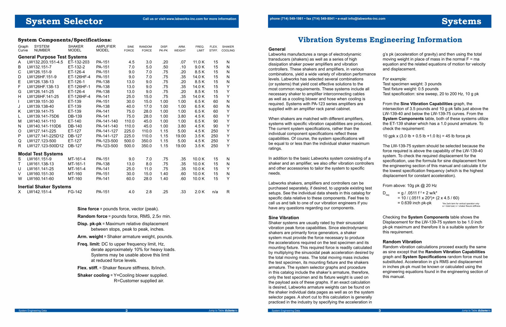
System Components/Specifications:Graph SYSTEM SHAKER AMPLIFIER SINE RANDOM DISP. ARM. FREQ. FLEX. SHAKERCurve NUMBER MODEL MODEL FORCE FORCE PK-PK WEIGHT LIMIT STIFF. COOLING
General Purpose Test SystemsA LW132.203.151-4.5 ET-132-203 PA-151 4.5 3.0 .20 .07 11.0 K 15 NB LW132.151-7 ET-132-2 PA-151 7.0 5.0 .50 .10 9.0 K 15 NC LW126.151-9 ET-126-4 PA-151 9.0 7.0 .75 .20 8.5 K 15 ND LW126HF.151-9 ET-126HF-4 PA-151 9.0 7.0 .75 .35 14.0 K 15 NE LW126.138-13 ET-126-1 PA-138 13.0 9.0 .75 .20 8.5 K 15 NF LW126HF.138-13 ET-126HF-1 PA-138 13.0 9.0 .75 .35 14.0 K 15 YG LW126.141-25 ET-126-4 PA-138 13.0 9.0 .75 .20 8.5 K 15 YH LW126HF.141-25 ET-126HF-4 PA-141 25.0 15.0 .75 .35 14.0 K 15 YI LW139.151-30 ET-139 PA-151 30.0 15.0 1.00 1.00 6.5 K 60 NJ LW139.138-40 ET-139 PA-138 40.0 17.0 1.00 1.00 6.5 K 60 NK LW139.141-75 ET-139 PA-141 75.0 28.0 1.00 1.00 6.5 K 60 YL LW139.141-75D6 DB-139 PA-141 75.0 28.0 1.00 3.80 4.5 K 60 YM LW140.141-110 ET-140 PA-141-140 110.0 45.0 1.00 1.00 6.5 K 90 YN LW140.141-110D6 DB-140 PA-141-140 110.0 45.0 1.00 3.80 4.5 K 90 YO LW127.141-225 ET-127 PA-141-127 225.0 110.0 1.15 5.00 4.5 K 250 YP LW127.141-225D12 DB-127 PA-141-127 225.0 110.0 1.15 19.00 3.5 K 250 YQ LW127.123-500 ET-127 PA-123-500 500.0 350.0 1.15 5.00 4.5 K 250 YR LW127.123-500D12 DB-127 PA-123-500 500.0 350.0 1.15 19.00 3.5 K 250 Y
Modal Test SystemsS LW161.151-9 MT-161-4 PA-151 9.0 7.0 .75 .35 10.0 K 15 NT LW161.138-13 MT-161-1 PA-138 13.0 8.0 .75 .35 10.0 K 15 NU LW161.141-25 MT-161-4 PA-141 25.0 11.0 .75 .35 10.0 K 15 YV LW160.151-30 MT-160 PA-151 30.0 15.0 1.40 .60 10.0 K 15 NW LW160.141-60 MT-160 PA-141 60.0 28.0 1.40 .60 10.0 K 15 Y
Inertial Shaker SystemsX LW142.151-4 FG-142 PA-151 4.0 2.8 .25 .33 2.0 K n/a R
Sine force = pounds force, vector (peak).
Random force = pounds force, RMS, 2.5σ min.
Disp. pk-pk = Maximum relative displacement between stops, peak to peak, inches.
Arm. weight = Shaker armature weight, pounds.
Freq. limit: DC to upper frequency limit, Hz, derate approximately 10% for heavy loads. Systems may be usable above this limit at reduced force levels.
Flex. stiff. = Shaker flexure stiffness, lb/inch.
Shaker cooling = Y=Cooling blower supplied. R=Customer supplied air.
System Engineering Data Systems
System Selector
Vibration Systems Engineering InformationGeneralLabworks manufactures a range of electrodynamic transducers (shakers) as well as a series of high dissipation shaker power amplifiers and vibration controllers. These shakers and amplifiers, in various combinations, yield a wide variety of vibration performance levels. Labworks has selected several combinations (or systems) that yield cost effective solutions to the most common requirements. These systems include all necessary shaker to amplifier interconnecting cables as well as a cooling blower and hose when cooling is required. Systems with PA-123 series amplifiers are supplied with an amplifier rack panel cabinet.
When shakers are matched with different amplifiers, systems with specific vibration capabilities are produced. The current system specifications, rather than the individual component specifications reflect these capabilities. Of course, the system specifications will be equal to or less than the individual shaker maximum ratings.
In addition to the basic Labworks system consisting of a shaker and an amplifier, we also offer vibration controllers and other accessories to tailor the system to specific needs.
Labworks shakers, amplifiers and controllers can be purchased separately, if desired, to upgrade existing test setups. See the individual data sheets in this catalog for specific data relative to these components. Feel free to call us and talk to one of our vibration engineers if you have any questions regarding our components.
Sine VibrationShaker systems are usually rated by their sinusoidal vibration peak force capabilities. Since electrodynamic shakers are primarily force generators, a shaker system must provide the force necessary to produce the accelerations required on the test specimen and its mounting fixture. This required force is readily calculated by multiplying the sinusoidal peak acceleration desired by the total moving mass. The total moving mass includes the test specimen, its mounting fixture and the shakers armature. The system selector graphs and procedure in this catalog include the shaker’s armature, therefore, only the test specimen and its fixture weight is used on the payload axis of these graphs. If an exact calculation is desired, Labworks armature weights can be found on the shaker individual data pages as well as on the system selector pages. A short cut to this calculation is generally practiced in the industry by specifying the acceleration in
g’s pk (acceleration of gravity) and then using the total moving weight in place of mass in the normal F = ma equation and the related equations of motion for velocity and displacement.
For example: Test specimen weight: 3 pounds Test fixture weight: 0.5 pounds Test specification: sine sweep, 20 to 200 Hz, 10 g pk
From the Sine Vibration Capabilities graph, the intersection of 3.5 pounds and 10 g pk falls just above the LW-139-40 and below the LW-139-75 curves. From the System Components table, both of these systems utilize the ET-139 shaker which has a 1.0 pound armature. To check the requirement:
10 gpk x (3.0 lb + 0.5 lb +1.0 lb) = 45 lb force pk
The LW-139-75 system should be selected because the force required is above the capability of the LW-139-40 system. To check the required displacement for the specification, use the formula for sine displacement from the engineering section of this manual and calculate it for the lowest specification frequency (which is the highest displacement for constant acceleration).
From above: 10g pk @ 20 Hz
Dreq = g / .0511 f 2 + 2 w/k* = 10 / (.0511 x 202)+ (2 x 4.5 / 60) = 0.639 inch pk-pk *the 2w/k term for vertical operation only w = total load, k = shaker flexure stiffness
Checking the System Components table shows the Displacement for the LW-139-75 system to be 1.0 inch pk-pk maximum and therefore it is a suitable system for this requirement.
Random VibrationRandom vibration calculations proceed exactly the same as sine except that the Random Vibration Capabilities graph and System Specifications random force must be substituted. Acceleration in g’s RMS and displacement in inches pk-pk must be known or calculated using the engineering equations found in the engineering section of this manual.
Systems
System Engineering Data Systems

4 5Jump to Table of Contents Jump to Table of Contents
phone (714) 549-1981 • fax (714) 549-8041 • e-mail [email protected] us or visit www.labworks-inc.com for more information
ElectrodynamicShaker
Test ArticleFixture
Test Article(Device under Test)
FeedbackAccelerometer
Cooling Hose(If required)
Cooling Vacuum(If required)
Shaker DriveCable
System PowerAmplifier
Line (Mains)Power Cable
Vacuum PowerCable
(If required)
ControllerPower Cable
Vibration Test Controller
Vibration System Hook-up: Block Diagram
Vibration System Hook-up: Typical Hardware Components
Drive SignalCable
AccelerometerMounting Pad
AccelerometerCable
May plug into the system power Amplifier
DB-127-D12Electrodynamic
Shaker / Slip Table
HE-140-7RHead Expander
8636 Feedback Accelerometer
Cooling Hose(If required)
CB-146C o o l i n g
PA-123-500Power Amplifier
PA-138Power Amplifier
SG-121 Sine SweepVibration Test Controller
VL-144x DigitalSine-Random-Shock
Vibration Test Controller
AccelerometerMounting Pad
1761B3Accelerometer Cable
ET-139Electrodynamic
Shaker
Cooling Hose(If required)
CB-127Cooling Vacuum
CB-152Cooling Vacuum
Cooling Hose(If required)
Systems
Vibration System Hook-up Guides
System Components*n ET-127 Electrodynamic Shaker w/De-Gauss Coiln PA-123-3/2-500 Amplifier, De-Gauss & Field Supply n CB-127 Cooling Blowern Amplifier Cabinet n Interconnect Cables and Hoses
System Options*n VL-144 2 Ch. Sine, Random and Shock Controller n VL-145 1 Ch. Digital Controllern DB-127 DuoBasen HE-127 Head Expandern SC-121 Sine Servo Controller n SG-135 Manual Controller n CS-123 Current Source Signal Conditioner
LW127.123-500 Vibration System
General SpecificationsSine Force: 500 lbs force pkRandom Force: 350 lbf rms randomShock Force: 1,000 lbf pk shockFrequency Range: DC to 4,500 HzMax. Acceleration: 100 g pk, bare table 50 g pk, 5 lb. load 11 g pk, 40 lb. loadMax. Displacement: 1.0 inch pk-pk, bare tableCooling: Amplifier: forced air Shaker: cooling blowerPower Requirements: 5200 VA @ 208- 230V, 1ø, 50/60 Hz.
*See individual components for more detailed specifications and options.Standard trunnion allows shaker operation in any position from vertical to horizontal. CB-127 shaker cooling vacuum.
The LW127.123-500 is the largest of the current family of Labworks vibration test systems. Electrodynamic shaker systems consist of a shaker and a matching linear direct coupled power amplifier. Additional components are then added to the basic system to tailor it to your specific needs.
Your small system concerns deserve the same attention given to larger, more expensive system requirements. Unlike other manufacturers, Labworks has designed and manufactures both its shakers and matching amplifiers in- house. This insures that the components will provide optimal performance across the broad range of possible applications and that application and service information is available with one call to the source.
1.0
10
100
g's pk SINE
10 100 1K 10KFREQUENCY
System Capability
1.07
in. p
-p1.
0 in
.
.60
in.
Bare Table
Load = 5 lb.
50 lb.
70 in
./sec
p
Systems
LW127.123-500 500 Force Pound System

6 7Jump to Table of Contents Jump to Table of Contents
phone (714) 549-1981 • fax (714) 549-8041 • e-mail [email protected] us or visit www.labworks-inc.com for more informationSystems
System Components*n DB-127-12 Electrodynamic Shaker w/12” sq Slip Table Basen PA-123-3/2-500 Amplifier, De-Gauss & Field Supplyn CB-127 Cooling Blowern Amplifier Cabinet n Interconnect Cables and Hoses
System Options*n VL-144x 2 Ch. Sine, Random and Shock Controller n VL-145x 1 Ch. Sine and Random Digital Controllern SC-121 Sine Servo Controller n SG-135 Manual Controller n HE-127 Head Expandern AI-127 Pneumatic Base Isolation Kit
LW127.123-500D12
General SpecificationsSine Force: 500 lbs force pkRandom Force: 350 lbf rms randomShock Force: 1,000 lbf pk shockFrequency Range: Horizontal, w/Slip Table DC to 3,000 Hz Vertical, w/o Slip Table DC to 4,500 HzMax. Acceleration: Horizontal, w/Slip Table 26 g pk, bare table 13 g pk, 20 lb. load 6.3 g pk, 60 lb. load Vertical, w/o Slip Table 100 g pk, bare table 50 g pk, 5 lb. load 11 g pk, 40 lb. loadMax. Displacement: 1.0 inch pk-pk, bare tableCooling: Amplifier: forced air Shaker: cooling vacuumPower Requirements: 5200 VA @ 208- 230V, 1ø, 50/60 Hz.
*See individual components for more detailed specifications and options.LW127.123-500D12 500 Force Pound DuoBase System
The LW-127-500D12 is the largest of the current family of Labworks vibration test systems. Its large 12 inch Square oil film Slip Table mounting surface provides high load and off-center moment capability for applications where heavy or large loads are to be tested. The DB-127 also allows the ET-127 shaker to be uncoupled from the slip table and rotated into its vertical position allowing normal vertical testing of smaller components directly on the shakers armature. The Shakers internal high lateral stiffness carbon composite armature suspension reduces problems asso-ciated with off-center loads when operating vertically. The ET-127 Shaker in this system is equipped with a degauss coil to ensure low stray magnetic field for sensitive applications. The modular air cooled PA-123 amplifier is direct coupled to the shaker to give the maxi-mum performance at low and high frequencies. Digital meters display the system operating levels and complete shaker and user interlocks help protect the system from accidental abuse.
VL-144x/145xoption
AI-127option
DuoBase System LW127.123-225 Vibration System
General SpecificationsSine Force: 225 lbs force pkRandom Force: 110 lbf rms randomShock Force: 240 lbf pk shockFrequency Range: DC to 4,500 HzMax. Acceleration: 45 g pk, bare table 32 g pk, 2 lb. load 15 g pk, 10 lb. loadMax. Displacement: 1.0 inch pk-pk, bare tableCooling: Amplifier: forced air Shaker: cooling blowerPower Requirements: 3500 VA @100-125*, 200-240V, 1ø, 50/60 Hz.
System Components*n ET-127 Electrodynamic Shakern PA-141 Linear Power Amplifiern FS-127 Integrated Field Supplyn CB-127 Cooling Blower n Interconnect Cables and Hoses
System Options*n VL-144 2 Ch. Sine, Random and Shock Controller n VL-145 1 Ch. Digital Controllern SC-121 Sine Servo Controllern HE-127 Head Expandern AI-127 Pneumatic Base Isolation Kitn Rack Cabinetn Accelerometer Package
The LW-127-225 system is used when the test article size makes the ET-127 shaker the correct choice but test requirements do not demand the full rated shaker performance available from the LW-127-500 system.
*See individual components for more detailed specifications and options.
*Consult factory for low line voltage operation.
Standard trunnion allows shaker operation in any position. from vertical to horizontal. The PA-141 amplifier features switched 115 Vac power.
1.0
10
100
g's pk SINE
10 100 1K 10KFREQUENCY
System Capability
1.07
in. p
-p
1.0
in.
.90
in.
Bare Table
Load = 5 lb.
20 lb.
LW127.141-225 225 Force Pound System
Systems

8 9Jump to Table of Contents Jump to Table of Contents
phone (714) 549-1981 • fax (714) 549-8041 • e-mail [email protected] us or visit www.labworks-inc.com for more informationSystems
System Components*n DB-127-12 Electrodynamic Shaker w/12” sq Slip Table Basen PA-141-127 Amplifier & Field Supplyn CB-127 Cooling Blowern Interconnect Cables and Hoses
System Options*n VL-144x 2 Ch. Sine, Random and Shock Controller n VL-145x 1 Ch. Sine and Random Digital Controllern SC-121 Sine Servo Controller n SG-135 Manual Controllern HE-127 Head Expander n Amplifier Cabinet n AI-127 Pneumatic Base Isolation Kit
LW127.141-225D12
General SpecificationsSine Force: 225 lbs force pkRandom Force: 110 lbf rms randomShock Force: 240 lbf pk shockFrequency Range: Horizontal, w/Slip Table DC to 3,000 Hz Vertical, w/o Slip Table DC to 4,500 HzMax. Acceleration: Horizontal, w/Slip Table 12 g pk, bare table 5.8 g pk, 20 lb. load 2.9 g pk, 60 lb. load Vertical, w/o Slip Table 45 g pk, bare table 32 g pk, 5 lb. load 15 g pk, 10 lb. loadMax. Displacement: 1.0 inch pk-pk, bare tableCooling: Amplifier: forced air Shaker: cooling vacuumPower Requirements: 3500 VA @ 100-125*, 200-240V, 1ø, 50/60 Hz.
*See individual components for more detailed specifications and options.
LW127.141-225D12 225 Force Pound System
VL-144x/145xoption
AI-127option
The LW127.141-225 system utilizes the ET-127 shaker in a lower force output system. Suitable for larger loads that don’t require high vibra-tion levels, the 225 system offers the benefits of the larger shaker at a reduced price to give the maximum performance at low and high fre-quencies. Its large 12 inch Square oil film Slip Table mounting surface provides high load and off-center moment capability for applications where heavy or large loads are to be tested. The DB-127 also allows the ET-127 shaker to be uncoupled from the slip table and rotated into its vertical position allowing normal vertical testing of smaller components directly on the shakers armature. The Shakers internal high lateral stiffness carbon composite armature suspension reduces problems associated with off-center loads when operating vertically.. Dual meters display the system operating levels and complete shaker and user interlocks help pro-tect the system from accidental abuse.
DuoBase System LW140.141-110 Vibration System
General SpecificationsSine Force: 110 lbs force pkRandom Force: 45 lbf rms randomShock Force: 110 lbf pk shockFrequency Range: DC to 6,500 HzMax. Acceleration: 110 g pk, bare table 55 g pk, 1 lb. load 10 g pk, 10 lb. loadMax. Displacement: 1.0 inch pk-pk, bare tableCooling: Amplifier: forced air Shaker: cooling blowerPower Requirements: 3300 VA @100-125*, 200-240V, 1ø, 50/60 Hz.
System Components*n ET-140 Electrodynamic Shakern PA-141 Linear Power Amplifiern FS-140 Integrated Field Supplyn CB-152-140 Cooling Blower n Interconnect Cables and Hoses
System Options*n VL-144 2 Ch. Sine, Random and Shock Controller n VL-145 1 Ch. Digital Controllern SC-121 Sine Servo Controllern SG-135 Manual Sine Controllern HE-140 Head Expandern Rack Cabinetn Accelerometer Package (use with Controller option)
The LW-140-110 is a high performance system capable of very high acceleration (110 g, bare table). It is used for general purpose as well as modal testing. The shaker field supply is integrated into the power amplifier and includes a cooling interlock to protect the shaker.
*See individual components for more detailed specifications and options.
Standard trunnion allows shaker operation in any position from vertical to horizontal. The PA-141 features switched 115 Vac power provided on the amplifier for shaker cooling and optional instrumentation.
10
g's pk SINE
10 100 1K 10KFREQUENCY
System Capability
1.0
in. p
-p.9
5 in
.
0.5
in.
Load = 1 lb.
10 lb.
100 Bare Table
Systems
LW140.141-110 110 Force Pound System
*Consult factory for low line voltage operation.
*Consult factory for low line voltage operation.

10 11Jump to Table of Contents Jump to Table of Contents
phone (714) 549-1981 • fax (714) 549-8041 • e-mail [email protected] us or visit www.labworks-inc.com for more informationSystems
System Components*n DB-140 Electrodynamic Shaker w/6” sq Flexure Table Basen PA-141-141 Amplifier & Field Supplyn CB-152-140 Cooling Blowern Interconnect Cables and Hoses
System Options*n VL-144x 2 Ch. Sine, Random and Shock Controller n VL-145x 1 Ch. Sine and Random Digital Controllern SC-121 Sine Servo Controller n SG-135 Manual Controllern HE-140 Head Expandern Amplifier Cabinet
LW140.141-110D6
General SpecificationsSine Force: 110 lbs force pkRandom Force: 45 lbf rms randomShock Force: 110 lbf pk shockFrequency Range: DC to 6,500 HzMax. Acceleration: Horizontal, w/Slip Table 29 g pk, bare table 7 g pk, 15 lb. load 3.5 g pk, 30 lb. load Vertical, w/o Slip Table 110 g pk, bare table 55 g pk, 1 lb. load 10 g pk, 10 lb. loadMax. Displacement: 1.0 inch pk-pk, bare tableCooling: Amplifier: forced air Shaker: cooling vacuumPower Requirements: 3300 VA @ 100-125*, 200-240V, 1ø, 50/60 Hz.
*See individual components for more detailed specifications and options.
LW140.141-110D6 110 Force Pound System
The LW140.141-110D6 Flexure Table system com-bines our ET-140 shaker and PA-141 amplifier together with our 6 inch square Flexure suspension Table. This combination provides a large mounting surface with increased load carrying capacity for larger or heavier than normal test specimens not requiring the force of a larger Shaker system. The unique flexure suspension table guidance eliminates the requirement for the oil found in slip table systems. This oil-less design allows operation at other than the horizontal orientation, and adds increased suspension guidance reducing the effects of heavy and off-center loads on the shakers armature suspension system.. The Table flexures are fully rated for 1 inch p-p operation, and the shaker can be uncoupled from the table for operation in its normal vertical orientation with specimens mounted directly to the shakers armature.
The air cooled PA-141 amplifier is direct coupled to the shaker to give the maximum performance at low and high frequencies. Dual meters display the system oper-ating levels and complete shaker and user interlocks help protect the system from accidental abuse.
SC-121option
DuoBase System
CB-152included
LW139.141-75 Vibration System
General SpecificationsSine Force: 75 lbs force pkRandom Force: 28 lbf rms randomShock Force: 80 lbf pk shockFrequency Range: DC to 6,500 HzMax. Acceleration: 75 g pk, bare table 38 g pk, 1 lb. load 13 g pk, 5 lb. loadMax. Displacement: 1.0 inch pk-pkCooling: Amplifier: forced air Shaker: cooling blowerPower Requirements: 2200 VA @100-125*, 200-240V, 1ø, 50/60 Hz.
System Components*n ET-139 Electrodynamic Shakern PA-141 Linear Power Amplifiern CB-152-139 Cooling Blower n Interconnect Cables and Hoses
System Options*n VL-144 2 Ch. Sine, Random and Shock Controller n VL-145 1 Ch. Digital Controllern SC-121 Sine Servo Controllern SG-135 Manual Sine Controllern HE-139 Head Expandern Rack Cabinet
The LW139.141-75 is our most powerful permanent magnet shaker system. This system is intended for use when test specifications require full performance from the ET-139 shaker. It is used for general purpose as well as modal testing because the linear power amplifier can be operated in either voltage or current source mode as test specifications require.
*See individual components for more detailed specifications and options.
Standard trunnion allows shaker operation in any position from vertical to horizontal. The PA-141 features switched 115 Vac power provided on the amplifier for shaker cooling and optional instrumentation.
1.0
10
100
g's pk SINE
10 100 1K 10KFREQUENCY
System Capability
1.0
in. p
-p.9
5 in
.
83 in
.
Bare Table
Load = 1 lb.
5 lb.
Systems
LW139.141-75 75 Force Pound System
*Consult factory for low line voltage operation.
*Consult factory for low line voltage operation.

12 13Jump to Table of Contents Jump to Table of Contents
phone (714) 549-1981 • fax (714) 549-8041 • e-mail [email protected] us or visit www.labworks-inc.com for more informationSystems
System Components*n DB-139 Electrodynamic Shaker w/6” sq Flexure Table Basen PA-141-139 Amplifier & Field Supplyn CB-152-139 Cooling Blowern Interconnect Cables and Hoses
System Options*n VL-144x 2 Ch. Sine, Random and Shock Controller n VL-145x 1 Ch. Sine and Random Digital Controllern SC-121 Sine Servo Controller n SG-135 Manual Controllern HE-139 Head Expandern Amplifier Cabinet
LW139.141-75D6 DuoBase System
General SpecificationsSine Force: 75 lbs force pkRandom Force: 28 lbf rms randomShock Force: 75 lbf pk shockFrequency Range: DC to 6,500 HzMax. Acceleration: Horizontal, w/Slip Table 20 g pk, bare table 5.5 g pk, 10 lb. load 3.2 g pk, 20 lb. load Vertical, w/o Slip Table 75 g pk, bare table 38 g pk, 1 lb. load 13 g pk, 5 lb. loadMax. Displacement: 1.0 inch pk-pk, bare tableCooling: Amplifier: forced air Shaker: cooling vacuumPower Requirements: 2,200 VA @ 100-125*, 200-240V, 1ø, 50/60 Hz.
*See individual components for more detailed specifications and options.
LW139.141-75D6 75 Force Pound System
SC-121option
The LW139.141-75D6 Flexure Table system combines our ET-139 permanent magnet field shaker and PA-141 amplifier together with our 6 inch square Flexure suspension Table. This combination provides a large mounting surface with increased load carrying capac-ity for larger or heavier than normal test specimens not requiring the force of a larger shaker system. The unique flexure suspension table guidance eliminates the requirement for the oil found in slip table systems. This oil-less design allows operation at other than the horizontal orientation, and adds increased sus-pension guidance reducing the effects of heavy and off-center loads on the shakers armature suspension system.. The Table flexures are fully rated for 1 inch p-p operation, and the shaker can be uncoupled from the table for operation in its normal vertical orienta-tion with specimens mounted directly to the shakers armature.
The air cooled PA-141 amplifier is direct coupled to the shaker to give the maximum performance at low and high frequencies. Dual meters display the system oper-ating levels and complete shaker and user interlocks help protect the system from accidental abuse.
LW139.138-40 Vibration System
General SpecificationsSine Force: 40 lbs force pkRandom Force: 17 lbf rms randomShock Force: 75 lbf pk shockFrequency Range: DC to 6,500 HzMax. Acceleration: 40 g pk, bare table 20 g pk, 1 lb. load 6.7 g pk, 5 lb. loadMax. Displacement: 1.0 inch pk-pk, bare tableCooling: Amplifier: forced air Shaker: natural convectionPower Requirements: 1000 VA @100, 120, 220, or 240V, 1ø, 50/60 Hz.
System Components*n ET-139 Electrodynamic Shakern PA-138 Linear Power Amplifiern Interconnect Cables and Hoses
System Options*n VL-144 2 Ch. Sine, Random and Shock Controller n VL-145 1 Ch. Digital Controllern SC-121 Sine Servo Controllern SG-135 Manual Sine Controllern Rack Cabinetn HE-139 Head Expander *See individual components for more detailed specifications and options.
Standard trunnion allows shaker operation in any position from vertical to horizontal. The hook-up requirements on the PA-138 are simple making the system highly portable.
The LW139.138-40 system is an excellent choice for modal testing due to the small shaker size, large displacement and absence of cooling hoses. Due to its compact size, this system is highly portable. The power amplifier has the option of being operated in the current source mode to facilitate modal testing. The large armature table facilitates general vibration testing of components and subassemblies with the amplifier in voltage source mode.
1.0
10
100
g's pk SINE
100 1K 10KFREQUENCY
System Capability
1.0
in. p
-p.9
5 in
.
.83
in.
Bare Table
Load =1 lb.
5 lb.
10
Systems
LW-139-40 40 Force Pound System
*Consult factory for low line voltage operation.
CB-152included
14 15Jump to Table of Contents Jump to Table of Contents
phone (714) 549-1981 • fax (714) 549-8041 • e-mail [email protected] us or visit www.labworks-inc.com for more information
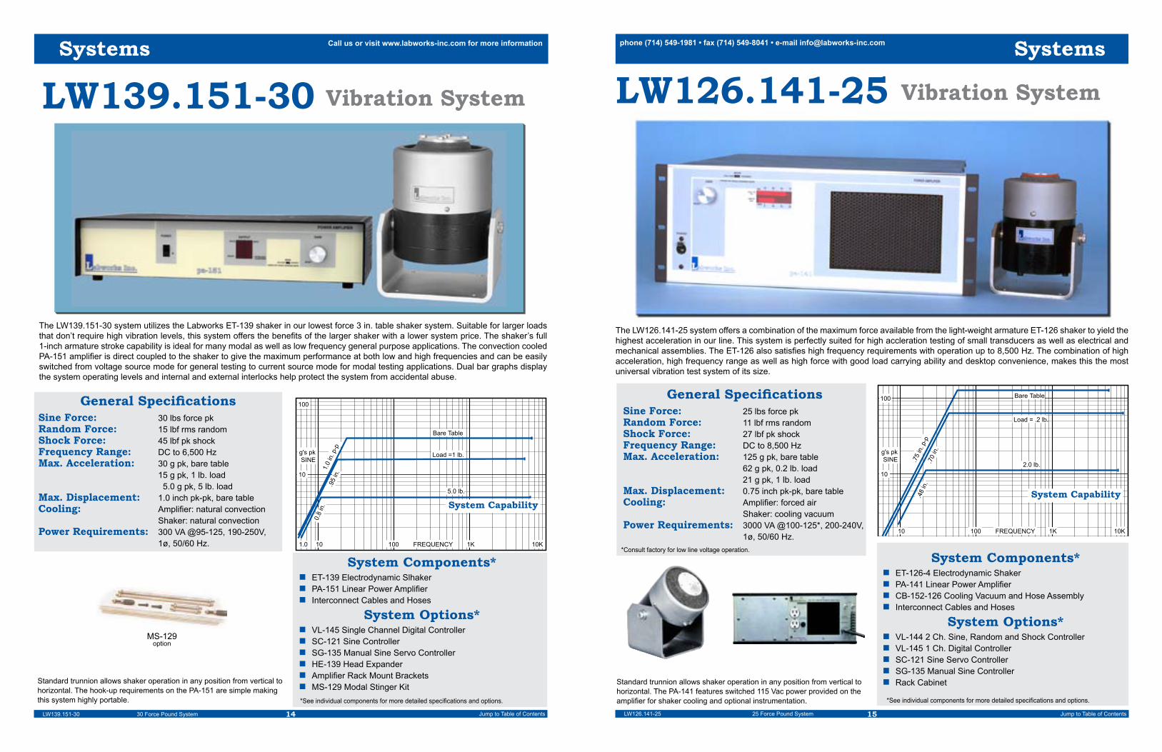
LW139.151-30 Vibration System
General SpecificationsSine Force: 30 lbs force pkRandom Force: 15 lbf rms randomShock Force: 45 lbf pk shockFrequency Range: DC to 6,500 HzMax. Acceleration: 30 g pk, bare table 15 g pk, 1 lb. load 5.0 g pk, 5 lb. loadMax. Displacement: 1.0 inch pk-pk, bare tableCooling: Amplifier: natural convection Shaker: natural convectionPower Requirements: 300 VA @95-125, 190-250V, 1ø, 50/60 Hz.
System Components*n ET-139 Electrodynamic Slhakern PA-151 Linear Power Amplifiern Interconnect Cables and Hoses
System Options*n VL-145 Single Channel Digital Controllern SC-121 Sine Controllern SG-135 Manual Sine Servo Controllern HE-139 Head Expandern Amplifier Rack Mount Brackets n MS-129 Modal Stinger Kit *See individual components for more detailed specifications and options.
Standard trunnion allows shaker operation in any position from vertical to horizontal. The hook-up requirements on the PA-151 are simple making this system highly portable.
1.0
10
100
g's pk SINE
100 1K 10KFREQUENCY
System Capability
1.0
in. p
-p.9
5 in
.
0.8
in.
Bare Table
Load =1 lb.
5.0 lb.
10
LW139.151-30 30 Force Pound System
Systems
The LW139.151-30 system utilizes the Labworks ET-139 shaker in our lowest force 3 in. table shaker system. Suitable for larger loads that don’t require high vibration levels, this system offers the benefits of the larger shaker with a lower system price. The shaker’s full 1-inch armature stroke capability is ideal for many modal as well as low frequency general purpose applications. The convection cooled PA-151 amplifier is direct coupled to the shaker to give the maximum performance at both low and high frequencies and can be easily switched from voltage source mode for general testing to current source mode for modal testing applications. Dual bar graphs display the system operating levels and internal and external interlocks help protect the system from accidental abuse.
MS-129option
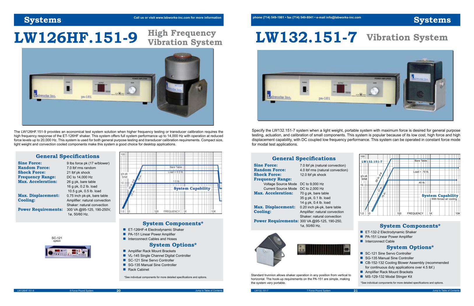
LW126.141-25 Vibration System
General SpecificationsSine Force: 25 lbs force pkRandom Force: 11 lbf rms randomShock Force: 27 lbf pk shockFrequency Range: DC to 8,500 HzMax. Acceleration: 125 g pk, bare table 62 g pk, 0.2 lb. load 21 g pk, 1 lb. loadMax. Displacement: 0.75 inch pk-pk, bare tableCooling: Amplifier: forced air Shaker: cooling vacuumPower Requirements: 3000 VA @100-125*, 200-240V, 1ø, 50/60 Hz.
System Components*n ET-126-4 Electrodynamic Shakern PA-141 Linear Power Amplifiern CB-152-126 Cooling Vacuum and Hose Assembly n Interconnect Cables and Hoses
System Options*n VL-144 2 Ch. Sine, Random and Shock Controller n VL-145 1 Ch. Digital Controllern SC-121 Sine Servo Controllern SG-135 Manual Sine Controllern Rack Cabinet
*See individual components for more detailed specifications and options.
Standard trunnion allows shaker operation in any position from vertical to horizontal. The PA-141 features switched 115 Vac power provided on the amplifier for shaker cooling and optional instrumentation.
10
g's pk SINE
10 100 1K 10KFREQUENCY
System Capability
.75
in. p
-p.7
0 in
.
.48
in.
Load = .2 lb.
2.0 lb.
100 Bare Table
Systems
LW126.141-25 25 Force Pound System
The LW126.141-25 system offers a combination of the maximum force available from the light-weight armature ET-126 shaker to yield the highest acceleration in our line. This system is perfectly suited for high accleration testing of small transducers as well as electrical and mechanical assemblies. The ET-126 also satisfies high frequency requirements with operation up to 8,500 Hz. The combination of high acceleration, high frequency range as well as high force with good load carrying ability and desktop convenience, makes this the most universal vibration test system of its size.
*Consult factory for low line voltage operation.

16 17Jump to Table of Contents Jump to Table of Contents
phone (714) 549-1981 • fax (714) 549-8041 • e-mail [email protected] us or visit www.labworks-inc.com for more information
LW126HF.141-25 High FrequencyVibration System
General SpecificationsSine Force: 25 lbs force pkRandom Force: 11 lbf rms randomShock Force: 27 lbf pk shockFrequency Range: DC to 14,000 Hz (20,000 @ 7 lbf)Max. Acceleration: 70 g pk, bare table 45 g pk, 0.2 lb. load 18.5 g pk, 1 lb. loadMax. Displacement: 0.75 inch pk-pk, bare tableCooling: Amplifier: forced air Shaker: cooling blowerPower Requirements: 3000 VA @100-125*, 200-240V, 1ø, 50/60 Hz. System Components*
n ET-126HF-4 Electrodynamic Shakern PA-141 Linear Power Amplifiern CB-152-126 Cooling Blower and Hose Assembly n Interconnect Cables and Hoses
System Options*n VL-144 Dual Channel Sine, Random and Shock Controller n VL-145 Single Channel Digital Controllern SC-121 Sine Servo Controllern SG-135 Manual Sine Controllern Rack Cabinet
*See individual components for more detailed specifications and options.
Systems
LW126HF.141-25 25 Force Pound System
The LW126HF.141-25 is a high performance system which makes full use of the compact ET-126HF high frequency shaker performance. This system offers full performance up to 14,000 Hz with operation at up to 7 lbf to 20,000 Hz. This system is used for both general purpose testing and transducer calibration requirements. The larger mounting surface of the ET-126HF easily supports the calibration of larger vibration transducers and smaller high frequency assemblies and components for general purpose testing. The shaker can support relatively heavy loads and is perfectly matched to the amplifier, which makes this the most versatile system of its size.
CB-152included
LW126.138-13 Vibration System
General SpecificationsSine Force: 13 lbs force pk (17 w/blower)Random Force: 8.0 lbf rms randomShock Force: 21 lbf pk shock Frequency Range: DC to 8,500 HzMax. Acceleration: 65 g pk, bare table 32 g pk, 0.2 lb. load 11 g pk, 1 lb. loadMax. Displacement: 0.75 inch pk-pk, bare tableCooling: Amplifier: forced air Shaker: natural convectionPower Requirements: 1000 VA @100, 120, 220, or 240V, 1ø, 50/60 Hz.
System Components*n ET-126-1 Electrodynamic Shakern PA-138 Linear Power Amplifiern Interconnect Cables and Hoses
System Options*n VL-144 2 Ch. Sine, Random and Shock Controller n VL-145 1 Ch. Digital Controllern SC-121 Sine Servo Controllern SG-135 Manual Sine Controllern Rack Cabinetn Accelerometer Packagen CB-126 Cooling Blower (>13 lbf)
*See individual components for more detailed specifications and options.
Standard trunnion allows shaker operation in any position from vertical to horizontal. The hook-up requirements on the PA-138 are simple, making the system portable.
10
g's pk SINE
10 100 1K 10KFREQUENCY
System Capability
.75
in. p
-p.7
0 in
.
.62
in.
Load = .2 lb.
1.0 lb.
100 Bare Table
1.0
Systems
LW126.138-13 13 Force Pound System
The LW126.138-13 system offers the maximum force available, without forced air cooling, from the light-weight armature ET-126 shaker. This compact desktop system is perfectly suited for general purpose testing of small transducers as well as electrical and mechanical assemblies. The ET-126 also satisfies most high frequency test requirements with operation up to 8,500 Hz. The combination of high acceleration, high frequency range as well as high force with good load carrying ability and desktop convenience, makes this a popular choice for medium acceleration level testing.
*Consult factory for low line voltage operation.

18 19Jump to Table of Contents Jump to Table of Contents
phone (714) 549-1981 • fax (714) 549-8041 • e-mail [email protected] us or visit www.labworks-inc.com for more information
LW126HF.138-13
General SpecificationsSine Force: 13 lbf pk (17 w/ opt. blower)Random Force: 8.0 lbf rms randomShock Force: 21 lbf pk shock Frequency Range: DC to 14,000 Hz (usable to 20,000 Hz)Max. Acceleration: 37 g pk, bare table 24 g pk, 0.2 lb. load 9.6 g pk, 1 lb. loadMax. Displacement: 0.75 inch pk-pk, bare tableCooling: Amplifier: forced air Shaker: natural convectionPower Requirements: 1000 VA @100, 120, 220, or 240V, 1ø, 50/60 Hz.
System Components*n ET-126-1 Electrodynamic Shakern PA-138 Linear Power Amplifiern Interconnect Cables and Hoses
System Options*n VL-145 1 Ch. Digital Controllern SC-121 Sine Servo Controllern SG-135 Manual Sine Controllern Rack Cabinetn CB-152 Cooling Blower (>13 lbf)
*See individual components for more detailed specifications and options.
LW126HF.138-13 13 Force Pound System
High FrequencyVibration System
Systems
The LW126HF.138-13 is a high performance system which incorporates the compact ET-126HF high frequency shaker. This system offers the maximum performance from the ET-126HF shaker without a cooling blower. Full system ratings are provided up to 14,000 Hz with reduced operation up to 20,000 Hz. This system is used for both general purpose high frequency testing and transducer calibration requirements. The larger mounting surface of the ET-126HF easily supports the calibration of most vibration transducers and smaller assemblies and components for general purpose testing not requiring high acceleration. The shaker can support relatively heavy loads and is perfectly matched to the amplifier, which makes this the most versatile system of its size.
CB-152option
LW126.151-9 Vibration System
General SpecificationsSine Force: 9.0 lbs force pkRandom Force: 7.0 lbf rms randomShock Force: 21 lbf pk shock Frequency Range: DC to 8,500 HzMax. Acceleration: 45 g pk, bare table 23 g pk, 0.2 lb. load 17 g pk, 0.5 lb. loadMax. Displacement: 0.75 inch pk-pk, bare tableCooling: Amplifier: natural convection Shaker: natural convectionPower Requirements: 300 VA @95-125, 190-250V, 1ø, 50/60 Hz.
System Components*n ET-126-4 Electrodynamic Shakern PA-151 Linear Power Amplifiern Interconnect Cables and Hoses
System Options*n VL-145 1 Ch. Digital Controllern SC-121 Sine Servo Controllern SG-135 Manual Sine Controllern Amplifier Rack Mount Bracketsn MS-129 Modal Stinger Kitn CB-126 Cooling Blower (>13 lbf)
*See individual components for more detailed specifications and options.Standard trunnion allows shaker operation in any position from vertical to horizontal. The hook-up requirements on the PA-151 are simple, making the system portable.
10
g's pk SINE
10 100 1K 10KFREQUENCY
System Capability
.75
in. p
-p.7
0 in
.
.62
in.
Load = 0.2 lb.
0.5 lb.
100
Bare Table
1.0
Systems
LW126.151-9 9 Force Pound System
The LW126.151-9 provides an economical test system solution when larger test loads require the large head of the ET-126 shaker operat-ing at reduced acceleration levels. This system has excellent high frequency capabilities and is used for both modal and general purpose testing. Compact size, light weight and convection cooled components make this system a good choice for desktop applications.
PA-151Rear Panel
20 21Jump to Table of Contents Jump to Table of Contents
phone (714) 549-1981 • fax (714) 549-8041 • e-mail [email protected] us or visit www.labworks-inc.com for more information
LW126HF.151-9
General SpecificationsSine Force: 9 lbs force pk (17 w/blower)Random Force: 7.0 lbf rms randomShock Force: 21 lbf pk shock Frequency Range: DC to 14,000 HzMax. Acceleration: 26 g pk, bare table 16 g pk, 0.2 lb. load 10.5 g pk, 0.5 lb. loadMax. Displacement: 0.75 inch pk-pk, bare tableCooling: Amplifier: natural convection Shaker: natural convectionPower Requirements: 300 VA @95-125, 190-250V, 1ø, 50/60 Hz.
System Components*n ET-126HF-4 Electrodynamic Shakern PA-151 Linear Power Amplifiern Interconnect Cables and Hoses
System Options*n Amplifier Rack Mount Bracketsn VL-145 Single Channel Digital Controllern SC-121 Sine Servo Controllern SG-135 Manual Sine Controllern Rack Cabinet
*See individual components for more detailed specifications and options.
LW126HF.151-9 9 Force Pound System
High FrequencyVibration System
Systems
SC-121option
The LW126HF.151-9 provides an economical test system solution when higher frequency testing or transducer calibration requires the high frequency response of the ET-126HF shaker. This system offers full system performance up to 14,000 Hz with operation at reduced force levels up to 20,000 Hz. This system is used for both general purpose testing and transducer calibration requirements. Compact size, light weight and convection cooled components make this system a good choice for desktop applications.
LW132.151-7 Vibration System
General SpecificationsSine Force: 7.0 lbf pk (natural convection)Random Force: 4.0 lbf rms (natural convection)Shock Force: 12.0 lbf pk shockFrequency Range: Voltage Source Mode DC to 9,000 Hz Current Source Mode DC to 2,000 HzMax. Acceleration: 70 g pk, bare table 35 g pk, 0.1 lb. load 14 g pk, 0.4 lb. loadMax. Displacement: 0.20 inch pk-pk, bare tableCooling: Amplifier: natural convection Shaker: natural convectionPower Requirements: 300 VA @95-125, 190-250, 1ø, 50/60 Hz. System Components*
n ET-132-2 Electrodynamic Shakern PA-151 Linear Power Amplifiern Interconnect Cable
System Options*n SC-121 Sine Servo Controllern SG-135 Manual Sine Controllern CB-152-132 Cooling Blower Assembly (recommended for continuous duty applications over 4.5 lbf.)n Amplifier Rack Mount Bracketsn MS-129-132 Modal Stinger Kit
*See individual components for more detailed specifications and options.
Standard trunnion allows shaker operation in any position from vertical to horizontal. The hook-up requirements on the PA-151 are simple, making the system very portable.
Specify the LW132.151-7 system when a light weight, portable system with maximum force is desired for general purpose testing, actuation, and calibration of small components. This system is popular because of its low cost, high force and high displacement capability, with DC coupled low frequency performance. This system can be operated in constant force mode for modal test applications.
10
g's pk SINE
100 1K 10KFREQUENCY
System Capability
.50
in. p
-p.1
7 in
.
Load = .10 lb.
.40 lb.
100
Bare Table
1.0
.15
in.
10
LW132.151-7
With forced air cooling
Systems
LW132.151-7 7 Force Pound System

22 23Jump to Table of Contents Jump to Table of Contents
phone (714) 549-1981 • fax (714) 549-8041 • e-mail [email protected] us or visit www.labworks-inc.com for more information
LW132-203.151-4.5 VibrationSystem
General SpecificationsSine Force: 4.5 lbs force pkRandom Force: 3.2 lbf rms randomShock Force: 9.6 lbf pk shockFrequency Range: Voltage Source Mode DC to 11,000 Hz Current Source Mode DC to 14,000 HzMax. Acceleration: 64 g pk, bare table 26 g pk, 0.1 lb. load 9.6 g pk, 0.4 lb. loadMax. Displacement: 0.20 inch pk-pk, bare tableCooling: Amplifier: natural convection Shaker: natural convectionPower Requirements: 200 VA @95-125, 190-250V, 1ø, 50/60 Hz. System Components*
n ET-132-203 Electrodynamic Shakern PA-151 Linear Power Amplifiern Interconnect Cables and Hoses
System Options*n Amplifier Rack Mount Bracketsn SC-121 Sine Servo Controllern SG-135 Manual Sine Controllern Rack Cabinetn MS-129-132 Modal Stinger Kit
*See individual components for more detailed specifications and options.
Specify the LW132-203.151-4.5 system when a light weight, portable system with maximum high frequency is desired for the general purpose testing and calibration of small components. This system is popular because of its low mass armature, high frequency capability, enhanced random vibration performance, and it is one of the smallest shakers available capable of DC (linear actuator) operation.
10
g's pk SINE
100 1K 10KFREQUENCY
System Capability
.20
in. p
-p.1
7 in
.
Load = .10 lb.
.40 lb.
100 Bare Table
1.0
.15
in.
10
LW132-203.151-4.5
LW132-203.151-4.5 4.5 Force Pound System
SC-121option
Systems
LW160.141-60 Modal Test System
General SpecificationsSine Force: 60 lbs force pkRandom Force: 28 lbf rms randomShock Force: 70 lbf pk shockFrequency Range: DC to 8,000 HzMax. Acceleration: 100 g pk, bare table 38 g pk, 1 lb. load 11 g pk, 5 lb. loadMax. Displacement: 1.4 inch pk-pk, bare tableCooling: Amplifier: forced air Shaker: cooling blowerPower Requirements: 2200 VA @100-125*, 200-240V, 1ø, 50/60 Hz.
System Components*n MT-160 Electrodynamic Shakern PA-141 Linear Power Amplifiern CB-146-160 Cooling Vacuumn MS-129-160 Modal Stinger Kit
System Options*n VL-144 2 Ch. Sine, Random and Shock Controller n VL-145 1 Ch. Digital Controllern SC-121 Sine Servo Controllern SG-135 Manual Sine Controllern Rack Cabinet *See individual components for more detailed specifications and options.
Standard trunnion allows shaker operation in any position from vertical to horizontal. Shaker body and trunnion through-hole allows long stinger and tension wire modal testing.
1.0
10
100
g's pk SINE
100 1K 10KFREQUENCY
System Capability
1.4
in. p
-p
Bare Table
Load =1 lb.
5.0 lb.
10
Systems
LW160.141-60 60 Force Pound Modal Test System
The LW160.141-60 system utilizes the Labworks MT-160 thruster and PA-141 linear power amplifier to form our highest performance modal test system. The thruster’s full 1.4 inch stroke capability, low suspension spring rate and light-weight armature makes this system ideal for most modal test applications. The thruster body features a through hole, and a single collet or thread load attachment to accommodate both tension wire and stinger modal testing. The PA-141 amplifier is direct coupled to the shaker to give the maximum performance from DC through high frequencies and can be easily switched from voltage source mode to current source mode for force input testing applica-tions. The amplifiers voltage-proportional-to-current amplifier signal output facilitates servoed force operation. Dual bar graphs display the system operating levels and internal and external interlocks help protect the system from accidental abuse.
MS-129
PA-141 Rear Panel
*Consult factory for low line voltage operation.

24 25Jump to Table of Contents Jump to Table of Contents
phone (714) 549-1981 • fax (714) 549-8041 • e-mail [email protected] us or visit www.labworks-inc.com for more information
LW160.151-30 Modal Test System
General SpecificationsSine Force: 30 lbs force pkRandom Force: 15 lbf rms randomShock Force: 38 lbf pk shockFrequency Range: DC to 8,000 HzMax. Acceleration: 50 g pk, bare table 19 g pk, 1 lb. load 5.4 g pk, 5 lb. loadMax. Displacement: 1.4 inch pk-pk, bare tableCooling: Amplifier: natural convection Shaker: natural convectionPower Requirements: 300 VA @95-125, 190-250V, 1ø, 50/60 Hz.
System Components*n MT-160 Electrodynamic Shakern PA-151 Linear Power Amplifiern MS-129-160 Modal Stinger Kitn Interconnect Cables and Hoses
System Options*n VL-144 2 Ch. Sine, Random and Shock Controllern VL-145 1 Ch. Digital Controllern SC-121 Sine Controllern SG-135 Manual Sine Servo Controllern Amplifier Rack Mount Brackets
*See individual components for more detailed specifications and options.
1.0
10
100
g's pk SINE
100 1K 10KFREQUENCY
System Capability
1.4
in. p
-p
Bare Table
Load =1 lb.
5.0 lb.
10
LW160.151-30 30 Force Pound Modal Test System
Systems
MS-129
The LW160.151-30 system utilizes the Labworks MT-160 thruster and convection cooled PA-151 linear power amplifier to form our most popular convection cooled permanent magnet field modal test system. The thruster’s full 1.4 inch stroke capability, low suspension spring rate and light weight armature makes this system ideal for most modal test applications. The thruster body features a through hole, and a single collet or thread load attachment to accommodate both tension wire and stinger modal testing. The convection cooled PA-151 amplifier is direct coupled to the shaker to give the maximum performance at both low and high frequencies and can be easily switched from voltage source mode to current source mode for force input testing applications. The amplifiers standard voltage-proportional-to-current amplifier signal output facilitates servoed operation. Dual bar graphs display the system operating levels and internal and external interlocks help protect the system from accidental abuse.
LW161.141-25
General SpecificationsSine Force: 25 lbs force pkRandom Force: 11 lbf rms randomShock Force: 27 lbf pk shockFrequency Range: DC to 10,000 HzMax. Acceleration: 70 g pk, bare table 18.5 g pk, 1 lb. load 4.7 g pk, 5 lb. loadMax. Displacement: 0.75 inch pk-pk, bare tableCooling: Amplifier: forced air Shaker: cooling vacuumPower Requirements: 2200 VA @100-125*, 200-240V, 1ø, 50/60 Hz.
System Components*n MT-161-4 Electrodynamic Shakern PA-141 Linear Power Amplifiern CB-152-161 Cooling Vacuum and Hose Assemblyn MS-129-161 Modal Stinger Kit n Interconnect Cables and Hoses
System Options*n VL-144 2 Ch. Sine, Random and Shock Controller n VL-145 1 Ch. Digital Controllern SC-121 Sine Servo Controllern SG-135 Manual Sine Controller
*See individual components for more detailed specifications and options.
1.0
10
100
g's pk SINE
100 1K 10KFREQUENCY
System Capability
.75
in. p
-p
Bare Table
Load =1 lb.
5.0 lb.
10
Systems
LW161.141-25 25 Force Pound Modal Test System
Modal Test System
The LW161.141-25 is a compact high performance modal test system which makes full use of our smaller MT-161modal test shaker perfor-mance. The thruster’s full .75 inch stroke capability, low suspension spring rate and light-weight armature makes this system ideal for most smaller modal test applications. The thruster body features a through hole, and a single collet or thread load attachment to accommodate both tension wire and stinger modal testing. The PA-141 amplifier is direct coupled to the shaker to give the maximum performance at DC through high frequencies, and can be easily switched from voltage source mode to current source mode for force input testing. The ampli-fiers voltage-proportional-to-current output signal facilitates servoed force test operation. Dual bar graphs display the system operating levels and internal and external interlocks help protect the system from accidental abuse.
Standard trunnion allows shaker operation in any position from vertical to horizontal. Shaker body and trunnion through-hole allows long stinger and tension wire modal testing.
PA-141Rear View
CB-152included
*Consult factory for low line voltage operation.

26 27Jump to Table of Contents Jump to Table of Contents
phone (714) 549-1981 • fax (714) 549-8041 • e-mail [email protected] us or visit www.labworks-inc.com for more information
MS-129
LW161.138-13
General SpecificationsSine Force: 13 lbs force pk (17 w/opt. blower)Random Force: 8.0 lbf rms randomShock Force: 21 lbf pk shock Frequency Range: DC to 10,000 HzMax. Acceleration: 37 g pk, bare table 6 g pk, 1 lb. load 2.4 g pk, 5 lb. loadMax. Displacement: 0.75 inch pk-pk, bare tableCooling: Amplifier: forced air Shaker: natural convectionPower Requirements: 1000 VA @100, 120, 220, or 240V, 1ø, 50/60 Hz.
System Components*n MT-161-1 Electrodynamic Shakern PA-138 Linear Power Amplifiern MS-129-161 Modal Stinger Kitn Interconnect Cables and Hoses
System Options*n VL-144 2 Ch. Sine, Random and Shock Controller n VL-145 1 Ch. Digital Controllern SC-121 Sine Servo Controllern SG-135 Manual Sine Controller
*See individual components for more detailed specifications and options.
Standard trunnion allows shaker operation in any position from vertical to horizontal. The hook-up requirements on the PA-138 are simple, making the system portable.
1.0
10
100
g's pk SINE
100 1K 10KFREQUENCY
System Capability
.75
in. p
-p
Bare Table
Load =1 lb.
5.0 lb.
10
Systems
LW161.138-13 13 Force Pound Modal Test System
Modal Test System
The LW161.138-13 modal test system makes full use of our smaller MT-161 modal test shakers natural convection cooled performance. The thruster’s full .75 inch stroke capability, low suspension spring rate and light-weight armature makes this system ideal for most smaller modal test applications not requiring the MT-161’s full force. The thruster body features a through hole, and a single collet or thread load attachment to accommodate both tension wire and stinger modal testing. The PA-141 amplifier is direct coupled to the shaker to give the maximum performance at DC through high frequencies, and can be easily switched from voltage source mode to current source mode for force input testing. The amplifiers voltage-proportional-to-current output signal facilitates servoed force test operation. Dual bar graphs display the system operating levels and internal and external interlocks help protect the system from accidental abuse.
PA-138Rear View
LW161.151-9
General SpecificationsSine Force: 9.0 lbs force pkRandom Force: 7.0 lbf rms randomShock Force: 21 lbf pk shock Frequency Range: DC to 10,000 HzMax. Acceleration: 26 g pk, bare table 16 g pk, 0.2 lb. load 10 g pk, 0.5 lb. loadMax. Displacement: 0.75 inch pk-pk, bare tableCooling: Amplifier: natural convection Shaker: natural convectionPower Requirements: 300 VA @95-125, 190-250V, 1ø, 50/60 Hz.
System Components*n MT-161-4 Electrodynamic Shakern PA-151 Linear Power Amplifiern MS-129-161 Modal Stinger Kitn Interconnect Cables and Hoses
System Options*n Amplifier Rack Mount Bracketsn VL-145 1 Ch. Digital Controllern SC-121 Sine Servo Controllern SG-135 Manual Sine Controllern Rack Cabinet *See individual components for more detailed specifications and options.
Systems
LW161.151-9 9 Force Pound Modal Test System
Modal Test System
The LW161.151-9 system utilizes the compact Labworks MT-161 thruster and convection cooled PA-151 linear power amplifier to form our smallest dedicated modal test system. The thruster’s full 0.75 inch stroke capability, low suspension spring rate and light weight armature makes this system ideal for most small modal test applications. The thruster features a through hole, and a single collet or thread load attachment to accommodate both tension wire and stinger modal testing. The convection cooled PA-151 amplifier is direct coupled to the shaker to give the maximum performance at both low and high frequencies and can be easily switched from voltage source mode to current source mode for force input testing applications. The amplifiers standard voltage-proportional-to-current output signal facilitates servoed test operation. Dual bar graphs display the system operating levels and internal and external interlocks help protect the system from accidental abuse.
Standard trunnion allows shaker operation in any position from vertical to horizontal. The hook-up requirements on the PA-138 are simple, making the system portable.
MS-129
PA-151Rear View

28 29Jump to Table of Contents Jump to Table of Contents
phone (714) 549-1981 • fax (714) 549-8041 • e-mail [email protected] us or visit www.labworks-inc.com for more information
LW142.151-2
General SpecificationsSine Force: 2 lbf pk (nat. convection) 4 lbf pk (forced air cooling)Random Force: 1.4 lbf rms (nat. convection) 2.8 lbf pk (forced air cooling)Frequency Range: 10 to 3,000 HzMax. Acceleration: (2 lbf / 4 lbf) 6.0 / 12.0 g pk, bare table 4.6 / 9.3 g pk, 0.1 lb. load 2.7 / 5.5 g pk, 0.4 lb. loadMax. Displacement: 0.20 inch pk-pk, bare table 0.35 inch pk-pk, resonant loadCooling: Amplifier: natural convection Shaker: natural / forced airPower Requirements: 300 VA @95-125, 190-250V, 1ø, 50/60 Hz. System Options*
n SC-121 Sine Servo Controllern SG-135 Manual Sine Controllern Amplifier rack mount bracketsn Amplifier rack cabinet
*See individual components for more detailed specifications and options.
The thru-hole on the FG-142 allows single screw or easy stinger mounting, simplifying load attachment requirements. The two wire Hook up connec-tion on the PA-151/FG-142 is simple, making this system very portable.
Systems
LW142.151-2 2 Force Pound Inertial Shaker System
Inertial Shaker System
The LW142.151-2 system is the smallest in our expanding line of Inertial Shaker systems. The PA-151 amplifier easily supplies the power required to gain the maximum performance from the shaker, The mounting convenience of the FG-142 makes this system ideal when a light-weight, portable system is desired for general purpose testing as well as modal excitation of larger test specimens. The inertial shaker concept eliminates the need for fixturing, in most cases, because of its insensitivity to mounting postion and internal reaction mass design. Since there is no external armature mounting surface, (the whole transducer vibrates) simply mount the FG-142 to the test specimen, utiliz-ing its single through hole mounting, in any orientation desired and commence testing. Multiple shakers can be implemented on complex or compliant structures to gain a more uniform excitation than can be had from traditional shakers under these conditions. Operation up to 2 lbf is possible without cooling further simplifying the installation to that of running two small wires between the amplifier and the shaker. A small amount of filtered shop / small compressor air allows full force operation of the FG-142 up to 4 lbf.
PA-151Rear View
.01
in. p-p SINE
natural cooling
.002 10
LW142.151-2
10 lb
0.1 lb load
1 lb
.10 0.3 lb
3 lb
100FREQUENCY
Max Displacement
System Components*n FG-142 Inertial Shakern PA-151 Linear Power Amplifiern Interconnect Cables
ARMATUREFLEXURES
FORESHORTENINGFLEXURES
ARMATURE COIL
MAGNET STRUCTURE(BODY)
PERMANENTMAGNET
ARMATURE
DIAPHRAGM
TEST FIXTURE
TEST ARTICLE
VIBRATION AXIS
SHAKER CROSS-SECTION
TOP COVER
Shaker Engineering Information
Shakers
Electrodynamic ShakersLabworks shakers utilize normal current/force motor prin-ciples to generate vibratory force. Electrodynamic force is inherently linear, and offers wider bandwidth with lower noise and harmonic distortion than mechanical or hydrau-lic based vibration generation. Labworks shakers are air cooled eliminating requirements for oil and water used in conjunction with other types of shaker cooling.
Labworks electrodynamic shakers offer frequency response down to DC to insure good low frequency force capability. Upper frequency limits are controlled by the shaker armature’s mechanical resonances and are extended by careful design to reach frequencies higher than most test specimen vibration test requirements.
General DescriptionLabworks Electrodynamic shakers use a construction simi-lar to common loudspeakers to convert electrical current flow into mechanical force over the widest frequency range with minimal spectral distortion of the input waveform. This moving “voice coil” configuration offers a large test article attachment surface with a lightweight moving mass.
The shaker’s voice coil is attached to a suspended alumi-num support and test article attachment structure called the “armature”. The shaker’s armature is guided so that it is allowed to move relatively easily in the direction of the generated force and have the highest stiffness possible in all other directions. In this respect, shakers are primarily unidirectional vibration devices. It is extremely important that the armature suspension be stiff in all transverse directions to minimize any lateral deflections caused by load attachment that could cause lateral armature coil deflection.
Labworks shakers utilize a “single-end” magnet structure configuration. This configuration offers several significant advantages over other types of magnet structures. Opti-mized, single-end shaker designs yield a larger armature coil diameter, giving these shakers a larger mounting surface, which is desirable for easy test article attach-ment. The single-end magnet structure also offers the easiest physical access for inspection and maintenance. No shaker body disassembly is required to service any dynamic component of the shaker.
Carbon fiber flexure components are used in the armature suspension to maximize the available dynamic stroke while maintaining high lateral stiffness. Minimal use of rubber in the armature suspension reduces velocity related damping
losses, therefore allowing higher velocity and better low frequency distortion characteristics.
Force GenerationElectrodynamic shakers are inherently force generators. Electrical current flowing in the armature coil interacts with the strong DC magnetic field of the shaker’s magnet structure (body) to produce physical force. This force can be taken as being generated between the armature coil and the shaker’s body. In this respect, since the armature is free to move relative to the body in the direction of the force, both the shaker’s armature (and its attached test article) and the shaker’s body are subjected to the gen-erated force. If the armature coil current is varied, as in alternating vibration excitation, both the armature and the shaker body will be accelerated in response to
Transducers Shaker Engineering Data

30 31Jump to Table of Contents Jump to Table of Contents
phone (714) 549-1981 • fax (714) 549-8041 • e-mail [email protected] us or visit www.labworks-inc.com for more informationShakersthis force and will each respond according to their inher-ent mass, with vibratory motion, each independent of the other.
Shaker magnetic structures are designed to have extremely high magnetic fields concentrated in the internal area of the armature coil. Further, since high magnetic fields can be detrimental to some test article operation and test results, the magnet structure is usually designed to have a minimum of “stray” magnetic flux outside of the shaker body. This is especially significant in the area of test article attachment at the “top” of the armature. Exclu-sive use of high energy, centrally located magnets or field coils is extremely effective in both these areas.
Force generated by the interaction of the armature coil and the body DC field is proportional to the current flowing in the coil and the strength of the DC field. The generated force can be found from the following equation. where: F=Armature coil force F=KBLI K=.885 x10-7 (English units) B=DC magnetic flux density L=Length of armature coil I =Armature coil current
Displacement LimitationsElectrodynamic shaker armature displacement is limited only by the axial length of the armature coil and the physi-cal limitations of the armature suspension system. Since most shakers are provided with an adequate axial coil length to maintain linear force generation at low frequen-cies, the primary limitation is that of physical interference of the suspension components. Since shakers have an available operating displacement window, it is most common to rate and discuss vibration test displacement in peak to peak terms. For this reason, most engineer-ing equations of motion involving vibration test will utilize displacement peak to peak (sometimes called “double amplitude displacement”).
The rated displacement of electrodynamic shakers is usu-ally the maximum relative displacement available between the armature and the shaker body/suspension. When considering the suitability of a shaker for a given test, it is important to consider the various factors that may reduce the available test article absolute displacement.
Since the same force that is applied to the armature coil is also applied to the shaker body, the shaker body is also accelerated and has a displacement definable by the normal equations of motion. This body motion can have the exact opposite phase relative to the armature motion and therefore, must share the available relative (rated) shaker armature displacement with the armature and test
article. In other words, the test article displacement added to the shaker body displacement must be less than the rated shaker displacement.
Another factor reducing the available displacement is the natural deflection of the armature suspension when a test article and fixture are placed on a shaker in the vertical shaker orientation. The weight of this added load offsets the armature downward and therefore reduces the avail-able downward armature displacement. Reducing the available stroke on one end of symmetrical alternating vibration reduces the allowable displacement by double the amount of the deflection.
For most test articles, the shaker body weight is signifi-cantly heavier than the test article, fixture and armature and its displacement motion can be ignored. In that case, the required displacement equation found in the Systems Engineering section applies: Dreq=g/.0511 f 2 + 2w/k.
A normal maximum unsupported load weight for a shaker in vertical orientation is that which will reduce the avail-able test article absolute displacement to 1/2 the rated, neglecting shaker body motion. This corresponds to the weight that will depress the suspension by 1/4 of the rated displacement. Labworks shakers are all designed with unusually large relative displacements to better accommo-date unsupported vertical operation.
Velocity LimitationsShaker velocity limitations stem primarily from internal inductive heating of conductive armature components and damping loss heating of over-damped suspension compo-nents. Labworks shakers are designed with low stray mag-netic fields which reduces the inductive heating. Minimal suspension damping is utilized and for most applications, Labworks shakers have no velocity limitation other than that imposed by the maximum acceleration and displace-ment specifications.
Shaker systems, however, can have velocity limitations due to back emf requirements on the system amplifier. Velocity limitations are rarely a concern with Labworks systems. Please call with your specifications if extremely high velocities are required.
PerformanceSine force 500 lbf pkRandom force 350 lbf rms Shock force 1000 lbf pkMax displacement Continuous pk-pk 1.0 in Between stops 1.2 inPhysicalArmature weight 5.0 lbSuspension stiffness 250 lb/inDimensions 21" H x 14.5" W x 14" DShaker weight 475 lbsOptionsn AI-127 (5 Hz) & SI-127 (10 Hz) Vibration Isolation Mounts.n LS-127 Pneumatic Payload Support.n DB-127 DuoBase Horizontal/Vertical Table.n TA-127 Thermal Chamber Interface.n M6 x 1 Metric Inserts.n Head Plates and Fixtures1 Please see systems ratings for additional specifications.2 Load dependent. Specifications subject to change.
General Specifications1
The ET-127 Electrodynamic Transducer is well suited for testing mechanical assemblies, packaging and printed circuit boards, as well as modal applications. The shaker incorpo-rates the latest high-tech composite materials and features a revolutionary “side load” restraint design in the armature suspension and guidance system. A host of “big shaker” options allow the ET-127 to be easily adapted to specific testing applications.
ET-127 Electrodynamic Shakern 500 pounds pk sine force
n 1.0 inch stroke
n 6.0 inch diameter table
n Unsupported Payloads up to 50 lbs
n Low stray magnetic field
n Frequency range2 DC-4,500 Hz
n Trunnion mounting base
13.00"dia
6.00"dia
9.7"
0.7"#1/4-20 mtg holes,5.000"bolt circle (5) holes
11.0"
11.00"typ .53
dia
Coolingoutlet
14.50"
Cableconnector
LL
Shakers
ET-127 500 Force Pound Shaker

32 33Jump to Table of Contents Jump to Table of Contents
phone (714) 549-1981 • fax (714) 549-8041 • e-mail [email protected] us or visit www.labworks-inc.com for more information
General Specifications1 DB-127-12 (-18)
Moving Element Weights -12 (-18) Slip Table weight 14 lbs (35 lbs) Shaker Armature weight 5 lbsMaximum Recommended Loads Table vertical/horizontal 100 lbs (200 lbs)Table mounting CG moment 100 in-lb (150in-lb)Table Mounting Surface (in.) 12 x 12 (18 x 18)Max. Bare Table Acceleration* 26 g pk (12 g pk)Bare Table Resonance Freq. 2300 Hz (2000 Hz)Maximum Useable Freq. 3000 Hz (2500 Hz)Displacement 1 inch pk-pkTable Mounting Hole Pattern Same as shakerOil Reservoir Capacity .4 gal (.8 gal) Complete Base + Shaker Wt. 1000 lb (1200 lb)Overall Dimensions (in.) 37.3 L x 23.5 H x 19.5 W
Optionsn Additional Mounting Holesn AI-DB127 Pneumatic (5 Hz) Isolation Mounts1 Please see appropriate Shaker or System data sheet for performance specifications.
DB-127 DuoBase Shaker
ET-127 Load Support & Isolation Mounts
Optional 5 Hz, AI-127 Pneumatic Vibration Isolation Mount.Far left...AI-127 mounted to ET-127 trunnion.
Standard 10 Hz, SI-127 Solid Vibration Isolation Mounts.Far left...SI-127 mounted to ET-127 trunnion.
n Large mounting surface
n 1.0 inch p-p stroke
n Integral oil moat and pump
n Horizontal and vertical testing
n Lightweight magnesium table
The DB-127 DuoBase Slip Table offers a large mounting surface with high load carrying capability for applications where lower acceleration levels are needed for large or heavy loads. The slip table utilizes a low pressure mineral oil film and rigid granite plate to provide support and guidance for the table. High rotational moments are reacted through the oil film to the base, allowing testing of high CG loads without risk of shaker suspension damage. The shaker can also be disconnected from the table, rotated to the vertical position, and then used as a normal vertical shaker without the additional weight of the Table. The base is supplied with standard machinery (15 Hz) isolation mounts.
Left...LS-127 Pneumatic Armature Payload Support is used when full displacement is required with heavy loads.
Shakers
3.93.0
1.1
Oil PumpStandard Isolator
OptionalAir Isolator
17.5
26.7
23.5
1.4 diaLifting Holes
21.5(23.5)
12.0(18.0)
37.3(43.3)
17.5
31.25(37.25)
12.0(18.0)
StandardShaker Hole
Pattern
DB-127-12(DB-127-18)All dimensions
in inches.
Accelerometermtg. Hole
L
ET-140
PerformanceSine force 110 lbf pkRandom force 75 lbf rms Shock force 225 lbf pkMax displacement Continuous pk-pk 1.0 in Between stops 1.03 inPhysicalArmature weight 1.0 lbSuspension stiffness 90 lb/inDimensions 11.5" H x 7.4" W x 6.5" DShaker weight 56 lbsOptionsn Vibration isolation mounts.n Modal stingers and mounts.n DB-140 Duobase Flexure Table
1 Please see systems ratings for additional specifications.2 Load dependent.Specifications subject to change.
General Specifications1
n 110 pounds pk sine forcen 1.0 inch stroken 3.25 inch diameter tablen Payloads up to 25 lbsn Low stray magnetic fieldn Frequency range2 DC-6,500 Hz.n Trunnion mounting basen Through-hole designThe ET-140 shaker's compact size, long stroke and lightweight armature make it well suited for modal as well as general vibration testing. Features include a rugged suspension system which minimizes test fixture requirements and related fixture guidance problems. The standard trunnion allows operation in any position from vertical to horizontal. It also facilitates bolting the shaker in place either with or without vibration isolation mounts. The shaker body’s through-hole design allows operation with modal stingers as well as tension wire set ups.
Electrodynamic Shaker
Shakers
ET-140 110 Force Pound Shaker
6.50"dia
3.25"dia
9.00"
11.68"
.70"
(5) #10-32 or 5mmremovable mtg inserts,(4) inserts on a 2.800"bolt circle & (1) at centerwith a 0.125 min. clearhole through the shakerbody and trunnion Base.
Input connector
4.70"
5.00"typ
.28dia
5/16-18 mtg holes5.75 bolt circle(4) holes
Cooling outlet
7.38"
Model ET-140 Outline and Installation details
L

34 35Jump to Table of Contents Jump to Table of Contents
phone (714) 549-1981 • fax (714) 549-8041 • e-mail [email protected] us or visit www.labworks-inc.com for more information
ET-139
PerformanceSine force Natural cooling 40 lbf pk With blower 75 lbf pkRandom force Natural coolling 28 lbf rms With blower 50 lbf rms Shock force 150 lbf pkMax displacement Continuous pk-pk 1.0 in Between stops 1.03 inPhysicalArmature weight 1.0 lbSuspension stiffness 60 lb/inDimensions 10.4" H x 7.4" W x 6.5" DShaker weight 28 lbsOptionsn Vibration isolation mounts. Modal stingers and mounts.n Cooling vacuum recommended continuous for operation above 35 lbf.n DB-139 Duobase Flexure Table
General Specifications1
The ET-139 is our most powerful permanent magnet shaker. It is an excellent choice for modal testing due to its compact size and long stroke. A large armature makes the shaker ideal for general vibration testing of components and subassemblies. The standard trunnion allows operation in any position from vertical to horizontal. A unique, all flexure, armature suspension design provides excellent axial com-pliance with high lateral stiffness. There are no rolling or sliding components to wear out and/or produce unwanted noise and distortion. The shaker body’s through-hole design allows operation with modal stingers as well as tension wire set ups.
Electrodynamic Shakern 75 pounds pk sine forcen 1.0 inch stroken 3.25 inch diameter tablen Payloads up to 7 lbs.n Low stray magnetic fieldn Frequency range2 DC-6,500 Hz.n Trunnion mounting basen Through-hole design
1 Please see systems ratings for additional specifications.2 Load dependent.Specifications subject to change.
Shakers
ET-139 75 Force Pound Shaker
6.50"DIA
3.25"DIA
7.00"
10.55"
.70"
Input connector
4.70"
5.00"TYP
.28DIA
(4) 5/16-18 MOUNTINGHOLES ON 5.75 B.C.
Model ET-139 Outline and Installation Details
7.38"
(5) #10-32 or 5mmremovable mtg inserts,(4) inserts on a 2.800"bolt circle & (1) at centerwith a 0.125 min. clearhole through the shakerbody and trunnion Base.
L
DB-140/DB-139 DuoBase Shaker
n Large mounting surface
n 1.0 inch p-p stroke
n Horizontal and vertical testing
n Lightweight magnesium table
Shakers
The DB-140 and -139 flexure tables offer a larger mount-ing surface with high-load carrying capability for applications where lower acceleration levels are needed with large or heavy loads. The flexure tables suspension systems utilize highly damped, oversized linear flexures and dynamic absorb-ers to provide support and guidance without the use of heavy granite surface plates or oil. Since no oil is used, the complete base system can be rotated into the vertical position to facili-tate vertical axis guided testing. Base mounting holes are pro-vided on the bottom as well as the rear of the base to facilitate vertical flexure table operation. The shaker can also be discon-nected from the table, rotated to the vertical position, and then used as a normal vertical shaker without the additional weight of the table. Rotating the base with the shaker in this posi-tion also allows horizontal operation without the flexure table. These bases are supplied with removable carrying handles.
Horizontal Vertical
Moving Element Weights Flexure Table weight 2.8 lbs Shaker Armature weight 1.0 lb Total Moving Element Weight 3.8 lbsMaximum Recommended Loads Table vertical/horizontal 40 lbs Table mounting CG moment 20 in-lb Shaker Only Vertical 15 lbsTable Mounting Surface (in.) 6 L x 7.5 WMax. Bare Table Acceleration* 29 gpk(140) / 20 gpk(139)Bare Table Resonance Freq. 3000 Hz Maximum Useable Freq. 4500 HzDisplacement 1 inch pk-pkTable Mounting Hole Pattern Same as shakerComplete Base + Shaker Wt. 100 lb (140) / 70 lb (139)Overall Dimensions (in.) 18.4 L x 9.1 H x 7.5 WOptions n Additional Mounting Holesn SI-DB140 / SI-DB139 Isolation Mounts1 Please see appropriate Shaker or System data sheet for performance specifications.
General Specifications1
DB-139/140 Flexure Table Option
L
10-32 or M5 threads2.800 in. dia bolt cir. or optional 1.000 in sq gridor combined attachment hole patterns.
6.00
3.50
7.50
3.75
9.13
12.0018.39
3.88
.8 /.9
6.1
Optional isolation mounts
Mounting holes.38 in. dia on a 12.00 x 5.38 in.sq. pattern
12.86
4.51
1.00 TYP
4.70 (140)6.00 (139)

36 37Jump to Table of Contents Jump to Table of Contents
phone (714) 549-1981 • fax (714) 549-8041 • e-mail [email protected] us or visit www.labworks-inc.com for more information
The Labworks ET-126 Electrodynamic Shaker is a rugged, full featured, small permanent magnet shaker. It is ideally suited for the production screening of small components or for larger transducer calibration systems. The shaker features a 2.125 inch diameter table with multiple attach-ment points, and an extraordinary 0.75 inch stroke. The ET-126 has a linearly compliant armature suspension that is particularly well suited to modal testing with a current source amplifier. The shaker body and trunnion through-hole allow operation with modal stingers as well as ten-sion wire set ups. The HF version of the ET-126 offer full performane up to 14,000 Hz with operation up to 20,000 Hz at up to 7 lbf.
General Specifications1
ET-126/ET-126HFn 25 pounds pk sine forcen .75 inch stroken 2.125 inch diameter tablen Payloads up to 3 lbs.n Low stray magnetic fieldn Frequency range2 DC-10 KHz. DC-14 KHz (HF)n Trunnion mounting basen Body and Trunnion Through hole
PerformanceSine force Natural cooling 13 lbf pk With blower 25 lbf pkRandom force Natural coolling 8 lbf rms With blower 17.5 lbf rms Shock force 53 lbf pk Max displacement Continuous pk-pk 0.75 in Between stops 0.75 inMaximum velocity 120 ips pk (100 ips pk / -HF)PhysicalArmature weight 0.20 lb (0.35 lb / -HF)Suspension stiffness 15 lb/inDimensions 6.5" H x 4.8" W x 4.25" DShaker weight 11 lbsOptionsn Vibration isolation mounts.n Modal stingers and mounts.n CB-152 Cooling Vacuum (required for operation above 13 lbf).
1 Please see systems ratings for additional specifications.2 Load dependent. Specifications subject to change.
ShakersElectrodynamicShaker
ET-126 25 Force Pound Shaker
4.25"
2.125"DIA
3.25"
7.00"
#6-32 mtg holes,1.800" hole circle(4) holes, thru
Input terminals
L
3.25"TYP
.281 DIA
3.25"
Cooling airoutlet (if req'd)
5.50"
Labworks Inc. Model ET-126B Shaker #6-32 mtg hole, thru(-HF models-Dual Thread:#10-32x.30 dp, #6-32 thru)
Labworks ET-132-2 and ET-132-203 Electrodynamic Trans-ducers are truly portable (only 6 pounds) permanent magnet shakers. With standard trunnions, they are ideally suited for the production screening of small components, modal test-ing or as displacement generators for, academic, biomedical and laboratory research. These shakers feature extremely rugged suspension systems. Carbon fiber composite leaf flexures and isolated linear bearings provide low distortion and eliminate the need for reaction wrenches when mount-ing loads to the armature.
Performance -203 -2Sine force 4.5 lbf pk 7 lbf pkRandom force 3 lbf rms 5 lbf rmsShock force, 11 msec 9 lbf pk 21 lbf pkMax displacementContinuous pk-pk .2 in .5 in.Between stops .35 in .55 in.PhysicalArmature weight .07 lb 0.1 lbSuspension stiffness 15 lbs/in 15 lbs/inDimensions 5.38" H x 3.6" W x 3.5" DShaker weight 6 lbs 6 lbs
Optionsn Modal stingers and mounts.n Load attachment threads (#10-32 std): #6-32, #8-32,M4x.7.n Cooling blower recommended for continuous operation above 4.5 lbf.
1 Please see systems ratings for additional specifications.2 Load dependent. Specifications subject to change.
General Specifications1
ET-132-2ET-132-203
n Up to 7 pounds pk sine forcen .5 inch stroken Threaded load mounting insertn Payloads up to 2 lbs.n Low stray magnetic fieldn Frequency range2 DC-11 KHz.n Trunnion mounting base
Shakers
Electrodynamic Shaker
ET-132-2 / ET-132-203 7 / 4.5 Force Pound Shakers
5.50"
2.75"
2.38"
3.50"
3.13"TYP
TRUNNIONMOUNTINGHOLES: .22"DIA ON 2.25"SQ. PATTERN(4) HOLES
MOUNTING SURFACE:.50" HEX W/ #10-32 UNF(std) THREAD
Labworks Inc ET-132 Shaker

38 39Jump to Table of Contents Jump to Table of Contents
phone (714) 549-1981 • fax (714) 549-8041 • e-mail [email protected] us or visit www.labworks-inc.com for more informationThrusters
MT-160
General Specifications1
Modal Thrustern 60 pounds pk sine forcen 1.5 inch stroken .005” to .125” dia. Colletn Stinger and Wire Through-Holen Low stray magnetic fieldn Frequency range2 DC-8,000 Hz.n Trunnion mounting base
1 Please see systems ratings for additional specifications.2 Load dependent.
Specifications subject to change.
Optionsn Vibration isolation mounts. Modal stingers and mounts.n Cooling blower required for operation above 30 lbf.
MT-160 60 Force Pound Modal Thruster
PerformanceSine force Natural cooling 30 lbf pk With blower 60 lbf pkMax displacement Continuous pk-pk 1.50 in Between stops 1.53 inMax velocity 120 ips pkMax Acceleration 200 gpk (resonant load)Frequency Range2 DC-8,000 HzFundamehntal Resonance2 5,000-6,000 HzStray magnetic fiels <15 gauss @ 1.5”Cooling @>13lbf 37 cfm /30 in H2o
PhysicalArmature weight 0.60 lbSuspension stiffness 20 lb/inDimensions 10.8" H x 7.4" W x 6.5" DShaker weight 28 lbs
The MT-160 thruster’s compact size, long stroke and lightweight armature make it well suited for all types of modal testing. The thruster has a compression collet and features a central through-hole suitable for modal stinger and pre-tensioned wire testing applications. The standard shaker trunnion allows the shaker to be operated in any axis from vertical to horizontal as well as easily mounted in wire tensioning tripods. The trunnion base also facilitates bolting the shaker in place for rigid applications or the use of adjustable mounting feet.
6.50"DIA
7.00"
10.75"
.90"
Collett Chuckadjustable:.005 dia to .125 dia Thruster thru hole clearance: .170 dia min.
Input connector
L
4.70"
5.00"TYP
.28 DIA, 4 holes1.0 DIA center hole
7.38"5.25"
.28 DIA typ
(4) 5/16-18 MOUNTINGHOLES ON 5.75 B.C.
5.50"
1.12"6.00"
2.30"
Thrusters
MT-161
PerformanceSine force Natural cooling 13 lbf pk With blower 25 lbf pkMax displacement Continuous pk-pk .70 in Between stops .75 inMax velocity 120 ips pkMax Acceleration 200 gpk (resonant load)Frequency Range2 DC-10,000 HzFundamehntal Resonance2 9,000-10,000 HzStray magnetic fiels <10 gauss @ 1.5”Cooling @>13lbf 30 cfm / 22 in H2o
PhysicalArmature weight 0.35 lbSuspension stiffness 15 lb/inDimensions 7.13" H x 4.8" W x 4.25" DShaker weight 11 lbs
General Specifications1
Modal Thrustern 25 pounds pk sine forcen .75 inch stroken .005” to .125” dia. Collet, #10-32, M5x.75 & 5/16-18 Thds.n Stinger and Wire Through-Holen Low stray magnetic fieldn Frequency range2 DC-10,000 Hz.n Trunnion mounting base
1 Please see systems ratings for additional specifications.2 Load dependent.
Specifications subject to change.
Optionsn Vibration isolation mounts. Modal stingers and mounts.n Cooling blower required for operation above 13 lbf.
MT-161 25 Force Pound Modal Thruster
The MT-161 thruster’s compact size, long stroke and lightweight armature make it well suited for all types of modal testing. The thruster has a compression collet and features a central through-hole suitable for modal stinger and pre-tensioned wire testing applications. The standard shaker trunnion allows the shaker to be operated in any axis from vertical to horizontal. The trunnion base also facilitates bolting the shaker in place for rigid applica-tions or the use of adjustable mounting feet.
Reliability is assured through the use of the latest composite materials in the unique, all flexure, armature suspension design. The design provides for low axial stiffness while retaining high lateral stiffness and has no rolling or sliding components to wear out and/or produce unwanted harmonics or distortion. When combined with the correct Labworks linear power amplifier, the system is unmatched for reliability, performance and cost.

40 41Jump to Table of Contents Jump to Table of Contents
phone (714) 549-1981 • fax (714) 549-8041 • e-mail [email protected] us or visit www.labworks-inc.com for more information
FG-142 Inertial Shakern 4 pounds pk sine force1
n 2.8 pounds pk random force1
n Low stray magnetic fieldn Frequency range 20-3,000 Hz.n Convenient through hole mounting
PerformanceSine force Natural cooling 2.0 lbf pk Forced air cooling 4.0 lbf pkRandom force Natural cooling 1.4 lbf rms Forced air cooling 2.8 lbf rms Shock force 4.5 lbf pk, 20 msec Max displacement Continuous pk-pk .35 in Between stops .35 inPhysicalDynamic element weight 0.33 lbMounting .141 in dia. through holeDimensions 2.0” D, 1.5” LGenerator weight .56 lbsOptionsn Cooling air inlet.
General Specifications2
1 Cooling air required for operation above 2 lbf. sine, 1.4 lbf random.2 Please see systems ratings for additional specifications.
Specifications subject to change.
Inertial Shaker
FG-142 4 Force Pound Inertial Shaker
The inertial shaker concept eliminates the need for fixturing, in most cases, because of its insensitivity to mounting postion and internal reaction mass design. Since there is no external armature mounting surface, (the whole transducer vibrates) simply mount the FG-142 to the test specimen, utilizing its single through hole mounting, in any orientation desired and commence testing. Multiple shakers can be implemented on complex or compliant structures to gain a more uniform exci-tation than can be had from traditional shakers under these conditions. Operation up to 2 lbf is possible without cooling further simplifying the installation to that of running two small wires between the amplifier and the shaker. A small amount of filtered shop / small compressor air allows full force operation of the FG-142 up to 4 lbf.
Mounting hole.141 dia. (#6 or3 mm thd) thru
2.000 dia
.310
.750 dia
1.500
Mounting surfaceeither endThrust Axis
Cooling airinlet (optional)
Outline and Installation DetailsFG-142 Force Generator
Shaker Audio Power AmplifiersGeneralLabworks manufactures a range of Audio Power Ampli-fiers primarily intended for use in driving vibration shakers. These amplifiers are high quality, low distortion, low noise units that can be used for any audio frequency application requiring high output current capability. All Labworks ampli-fiers are designed to tolerate highly reactive loads and will recover automatically from short circuit and over-tempera-ture conditions.
Unlike standard public address power amplifiers, these amps have DC output capability. The heat rejection ability of Labworks amplifiers is between 3 and 10 times that of amplifiers designed to drive loud speakers. The combina-tion of high output current, self protection, high heat rejec-tion, DC output, power-on interlock, and voltage or current source capability is what sets these amps apart from other high power audio amplifiers. It is just this combination of characteristics that make these amplifiers suitable for use with vibration shaker and other transducer applications.
Linear Power Output StageMost Labworks power amplifiers utilize class AB1 linear power output stages. This type of output configuration offers the maximum electrical efficiency consistent with the inherent low noise and wide bandwidth associated with class A operation.
Smaller shakers and vibration transducers are often used in reduced force applications with sensitivity to both con-ducted and radiated noise associated with Class D ampli-fiers. Further, these applications will usually benefit from a highly damped voltage source amplifier. The direct coupled solid state output of Labworks amplifiers, with no reactive or filter components in the output signal path, provides for maximum output damping with minimum conducted and radiated noise.
Heat RejectionOne by-product of high quality audio and Labworks linear power amplifiers, with linear output stages, is a higher heat rejection rate. To maintain high output currents at low output voltages, these types of amplifiers must dissipate significant amounts of heat. Along with limited or nonexis-tent low frequency output ability, the extremely limited heat rejection rate of public address amplifiers makes them all but unusable for shaker or high current transducer applica-tions. These amplifiers are designed to drive loudspeakers which are made intentionally inefficient with higher imped-ance to maintain flat frequency response. Amplifiers like these will usually falt on over-temperature or over-current when trying to drive shakers or high current transducers.
Some public address amplifiers can be used for shaker applications if low frequency operation is not needed and their cooling can be enhanced by adding extra cooling fins, cooling fan packages, etc. All Labworks amplifiers come standard with oversize heat sinks. All but our smallest amplifier, the PA-151, have low noise, variable speed, high volume cooling fans to insure unhindered performance in high current applications.
Shaker/Transducer ProtectionUnlike speaker applications, it is important that the shaker amplifier never be switched on or be automatically reset with its gain up. Uncontrolled, spurious output turn-on transients or automatic output restoration after an amplifier or interlock fault can result in a broken shaker.
Labworks amplifiers provide for external customer assign-able shutdown interlocks as well as power on interlock protection. This interlock protection insures that the ampli-fier gain must be fully down before the amplifier output is enabled. The external interlock can be used in conjunc-tion with a vibration controller or other critical test article parameters to shut the system power amplifier down.
Current Source CapabilityIn some applications involving constant force (instead of acceleration, displacement, etc.) it is desirable to have a completely undamped force source at the shaker. For these applications, the most desirable amplifier output characteristic is that of a current source instead of a volt-age source.
Unlike many amplifiers available, most Labworks models have dual mode operation capability and can be simply switched to operate as either a high frequency, highly damped voltage source or as a high impedance, low damping current source.
Amplifiers
Amplifiers Amplifier Engineering Data
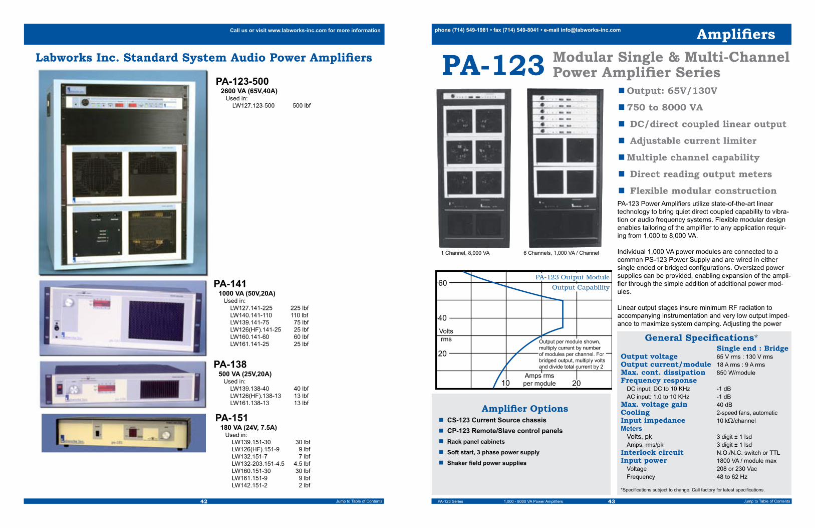
42 43Jump to Table of Contents Jump to Table of Contents
phone (714) 549-1981 • fax (714) 549-8041 • e-mail [email protected] us or visit www.labworks-inc.com for more information
Labworks Inc. Standard System Audio Power Amplifiers
PA-123-5002600 VA (65V,40A) Used in: LW127.123-500 500 lbf
PA-1411000 VA (50V,20A) Used in: LW127.141-225 225 lbf LW140.141-110 110 lbf LW139.141-75 75 lbf LW126(HF).141-25 25 lbf LW160.141-60 60 lbf LW161.141-25 25 lbf
PA-138500 VA (25V,20A) Used in: LW139.138-40 40 lbf LW126(HF).138-13 13 lbf LW161.138-13 13 lbf
PA-151180 VA (24V, 7.5A) Used in: LW139.151-30 30 lbf LW126(HF).151-9 9 lbf LW132.151-7 7 lbf LW132-203.151-4.5 4.5 lbf LW160.151-30 30 lbf LW161.151-9 9 lbf LW142.151-2 2 lbf
PA-123 Modular Single & Multi-ChannelPower Amplifier Series
n Output: 65V/130V
n 750 to 8000 VA
n DC/direct coupled linear output
n Adjustable current limiter
n Multiple channel capability
n Direct reading output meters
n Flexible modular construction
General Specifications* Single end : BridgeOutput voltage 65 V rms : 130 V rmsOutput current/module 18 A rms : 9 A rmsMax. cont. dissipation 850 W/moduleFrequency response DC input: DC to 10 KHz -1 dB AC input: 1.0 to 10 KHz -1 dBMax. voltage gain 40 dBCooling 2-speed fans, automatic Input impedance 10 kΩ/channelMeters Volts, pk 3 digit ± 1 lsd Amps, rms/pk 3 digit ± 1 lsdInterlock circuit N.O./N.C. switch or TTLInput power 1800 VA / module max Voltage 208 or 230 Vac Frequency 48 to 62 Hz
*Specifications subject to change. Call factory for latest specifications.
Amplifier Optionsn CS-123 Current Source chassisn CP-123 Remote/Slave control panelsn Rack panel cabinets
n Soft start, 3 phase power supply
n Shaker field power supplies
PA-123 Power Amplifiers utilize state-of-the-art linear technology to bring quiet direct coupled capability to vibra-tion or audio frequency systems. Flexible modular design enables tailoring of the amplifier to any application requir-ing from 1,000 to 8,000 VA.
Individual 1,000 VA power modules are connected to a common PS-123 Power Supply and are wired in either single ended or bridged configurations. Oversized power supplies can be provided, enabling expansion of the ampli-fier through the simple addition of additional power mod-ules. Linear output stages insure minimum RF radiation to accompanying instrumentation and very low output imped-ance to maximize system damping. Adjusting the power
1 Channel, 8,000 VA 6 Channels, 1,000 VA / Channel
Voltsrms
20
40
60
2010
Output Capability
PA-123 Output Module
Output per module shown,multiply current by numberof modules per channel. Forbridged output, multiply voltsand divide total current by 2
Amps rmsper module
Amplifiers
PA-123 Series 1,000 - 8000 VA Power Amplifiers

44 45Jump to Table of Contents Jump to Table of Contents
phone (714) 549-1981 • fax (714) 549-8041 • e-mail [email protected] us or visit www.labworks-inc.com for more information
Linear Power Amplifiers
n Digital voltage and current metersn Full internal and user interlocksn AC and DC inputs providedn Adjustable current limitern Anti-phase outputs for bridge or push-pull operationn Master/slave connection capablen Flexible modular construction
CP-123 Control Panel
The CS-123 current source chassis is designed to inter-face transparently with the CP-123. This combination along with any of the PA-123 series amplifiers forms a depend-able high impedance current source amplifier. A front panel switch on the CS-123 allows switching between voltage and current source amplifier output modes.
CS-123Current Source Chassis
CP-123 Rear panel
CS-123 Current Source Chassis
supply rail voltage, to properly match the amplifier output impedance to the load, assures efficient, direct coupled, operation.
Oversize heat sinks dissipate internal energy with minimum air flow rates. Dual-speed cooling fans provide quiet opera-tion during idle or normal dissipation conditions with plenty of additional capacity when needed.
Power up soft start relays and line power sensing interlock circuitry eliminate accidental output transients during turn-on and turnoff.
Complete self protection for over-temperature, over-current, and instantaneous dissipation, as well as normally open and normally closed external interlock loops are standard. This provides maximum system compatibility and reliability.
For additional information on single or multichannel modular amplifiers, please call the Labworks technical support staff. The CP-123 Control Panel is a compact, rack mounted
instrument, which provides convenient drive signal control. The CP-123 provides gain control (pre-amplification), power amplifier output voltage and current metering, adjustable output current limiting for transducer protection, and full function system safety interlocks.
The CP-123 may be used as a remote control panel, con-nected in master-slave configuration, if more than one control location is desirable. For multiple channel amplifiers, CP-123 Control Panels provide independent control for each channel. Power modules are simply connected into appro-priate groups.
Amplifiers
CS-123 / CP123 Current Source Chassis / Control Panel
PA-123-3/2-500 Linear Power Amplifier
The PA-123-3/2-500 houses a field and De-Gauss power supply specifically designed to drive the ET-127 shaker. It’s a class AB, air-cooled unit with a power output of 2,600 VA, and is made up of three separate interconnected chassis. The flexible PA-123 modular design allows this amplifier to be configured for use with other shakers.
The CP-123 Control Panel features a low noise preampli-fier, amplifier output voltage and current metering, adjust-able output current limiting, and complete interlock circuitry. The power and field supply chassis houses input power transformers, power supply circuitry, the shaker interface, shaker cooling blower power source, and field cooling interlock.
n Output: 65V, 2600 VA.
n DC/direct coupled linear output
n Adjustable current limiter
n Field and De-Gauss power for the ET-127 shaker
General Specifications*Output voltage 65 V rmsOutput current 40 A rmsMax. cont. dissipation 2250 WFrequency response DC input: DC to 10 KHz -1 dB AC input: 1.0 to 10 KHz -1 dBMax. voltage gain 40 dBCooling 2-speed fan, automatic Input impedance 10 kΩMeters Volts, pk 3 digit ± 1 lsd Amps, rms/pk 3 digit ± 1 lsdInterlock circuit Shaker, internal Over travel, cooling External, user N.O./N.C. switch or TTL Shaker field power 1,250 WInput power 5,200 VA max Voltage 208 or 230 Vac, 1ø Frequency 48 to 62 HzDimensions 28" H x 21" W x 20" DWeight 280 lbs
*Specifications subject to change. Call factory for latest specifications.
Amplifier Options n CS-123 Current Source chassis
4Ω 2Ω
1Ω
Voltsrms
Ampsrms
20
40
60
20 30 4010
.5Ω
Output Capability
Amplifiers
PA-123-500 2,600 VA Power Amplifier

46 47Jump to Table of Contents Jump to Table of Contents
phone (714) 549-1981 • fax (714) 549-8041 • e-mail [email protected] us or visit www.labworks-inc.com for more information
PA-123-2/2-65PA-123-1/2-40
Linear Power Amplifiers
The PA-123-X/2 amplifiers utilize standard PA-123 output modules and a CP-123 control panel/preamplifier. The number of output modules and power supply voltage is varied to match the load requirements. The PA-123-2/2-65 uses two output modules and full supply voltage. The PA-123-1/2-40 uses one output module and reduced supply voltage to match low impedance loads. The 2/2-65 can be configured to supply up to 130 Volts/18 Amps if required for high voltage loads.
A single chassis houses both the power supply as well as the output module(s) and is designed to mount in a stan-dard 19” rack panel.
General Specifications* 2/2-65 : 1/2-40Output voltage 65 V rms : 40 V rmsOutput current 36 A rms : 20 A rmsMax. cont. dissipation 1,700 W : 850 WFrequency response DC input: DC to 10 KHz -1 dB AC input: 1.0 to 10 KHz -1 dBMax. voltage gain 40 dBCooling 2-speed fan, automatic Input impedance 10 kΩMeters Volts, pk 3 digit ± 1 lsd Amps, rms/pk 3 digit ± 1 lsdInterlock circuit N.O./N.C. switch or TTL Input power 3,500 VA : 1750 VA Voltage 208 or 230 Vac, 1ø Frequency 48 to 62 HzDimensions 10.5" H x 19" W x 20" DWeight 85 lbs : 70 lbs*Specifications subject to change. Call factory for latest specifications.
Amplifier Optionsn CS-123 Current Source chassisn Rack mount cabinet
n Output: 65V, 2000 VA, or 40V, 750 VA.
n DC/direct coupled linear output
n Adjustable current limiter
n CP-123 control panel
n Full external interlock circuit
4Ω
2Ω
1Ω
Voltsrms
Ampsrms
20
2010
Output Capability-1/2-40
40
4Ω 2Ω
1Ω
Voltsrms
Ampsrms
20
40
60
20 30 4010
.5Ω
Output Capability-2/2-65
Amplifiers
PA-123-2/2 and PA-123-1/2 2,000 VA and 750 VA Power Amplifiers
n Output: 50V, 1000 VA
n Direct coupled linear output
n Voltage and current source mode
n External interlock circuitry
n Optional shaker field suppliesThe Labworks PA-141 Linear Power Amplifier has two operational modes. The amplifier can be used as either a wide-band, highly damped voltage source, or as a high impedance current source. Optional, internal DC field power supplies can be supplied for use with Labworks ET-140 and ET-127 Shakers. These options provide the convenience of a single chassis, as well as fully integrated power-up and cooling interlocks.
PA-141 Linear Power Amplifier
General Specifications*Output voltage 50 V rmsOutput current 20 A rmsMax. cont. dissipation 900 WFrequency response DC input: DC to 10 KHz -.6 dB AC input: 1.0 to 10 KHz -.6 dBMax. voltage gain 36 dBCooling 2-speed fan, automatic Input impedance 10 kΩMeters Volts, pk 19 segment ± 5 % Amps, rms 19 segment ± 5 % Interlock circuit External, user F.O. switch or TTL Shaker, internal, optional coolingOptional field power 1000 W maxInput power 2000 VA (3000 w/field) Voltage 208 or 230 Vac, 1ø Frequency 48 to 62 HzDimensions 7" H x 19" W x 17" DWeight 48 lbs
*Specifications subject to change. Call factory for latest specifications.
4Ω
2Ω
1Ω
Voltsrms
Ampsrms
20
40
2010
Output CapabilityPA-141
8Ω60
Amplifiers
PA-141 1,000 VA

48 49Jump to Table of Contents Jump to Table of Contents
phone (714) 549-1981 • fax (714) 549-8041 • e-mail [email protected] us or visit www.labworks-inc.com for more information
PA-138 Linear Power Amplifier
General Specifications*Output voltage 25 V rmsOutput current 20 A rmsMax. cont. dissipation 450 WFrequency response Voltage source: DC to 10 KHz -0.6 dB Current source: DC to 2 KHz -2 dB @ 4ΩMax. voltage gain 30 dBCooling 2-speed fan, automatic Input impedance 10 kΩMeters Volts, pk 19 segment ± 5 % Amps, rms 19 segment ± 5 % Interlock circuit External, user F.O. switch or TTLInput power 1000 VA max Voltage 100,120, 220, 240 V,1ø Frequency 48 to 62 HzDimensions 3.5" H x 19" W x 13" DWeight 24 lbs
*Specifications subject to change. Call factory for latest specifications.
n Output: 25V, 500 VA
n Direct coupled linear output
n Output voltage and current meters
n Voltage and current source modes
n Small size, high power
Amplifier Optionsn Rack panel cabinetn BNC signal cables
The Labworks PA-138 Linear Power Amplifier is a high quality, air-cooled, direct-coupled audio amplifier primarily intended for use with small vibration systems. Although this amplifier has been designed to directly drive low impedance loads, it can be used in any application requiring continuous duty, high quality, audio power.
PA-138 Amplifiers feature protection from both over current and over temperature insuring long term reliability. The ampli-fier has full interlock capabilities as well as peak voltage and RMS current bar graphs to monitor output.
4Ω2Ω
1Ω
Voltsrms
Ampsrms
10
20
2010
Output CapabilityPA-138
.5Ω
30
Amplifiers
PA-138 500 VA
Linear Power AmplifierPA-151
General Specifications2
Output voltage 25 or 20 V rmsOutput current 7.5 A rmsMax. cont. dissipation 180 WFrequency response Voltage Source: DC to 10 KHz -1 dB Current Source: DC to 2 KHz -2 dB @ 4ΩMax. voltage gain 28 dBMax. current gain 22 A/V Cooling Natural convectionInput impedance 10 kΩMeters Volts 9 segment bar graph Amps 9 segment bar graph Interlock circuit External, user F.C. switch or TTL, F.C.Input power 300 VA max Voltage 100-120, 200-240 V,1ø Frequency 48 to 62 HzDimensions 3.5" H x 17" W x 13" DWeight 19 lbs1 Switch selectable internal rail voltage allows impedance matching to load requirements2 Specifications subject to change. Call factory for latest specifications.
n Output: 25V or 20V, 180 VA1
n Direct coupled linear outputn Output voltage and current metersn Voltage and Current source modesn Convection cooling, no fansn Light weight, desktop amplifier
Amplifier optionsn Rack mount bracketsn Rack panel cabinet
Amplifiers
PA-151 180 VA Power Amplifier
The Labworks PA-151 Linear Power Amplifier is a high quality, convection-cooled, direct-coupled audio amplifier primarily intended for use with small vibration systems. Although this amplifier has been designed to directly drive low impedance loads, it can be used in any application requiring continuous duty, high quality, audio power. PA-151 Amplifiers feature protection from both over current and over temperature insuring long term reliability. The amplifier circuitry uses soft start technology for load protection and has external interlock capabilities as well as output voltage and current bar graphs. A voltage-proportional-to-output-current signal output is provided for modal test and other applications requiring force monitoring. A unique dynamic output drive circuit provides high random peak output current for increased random and shock vibration system performance.

50 51Jump to Table of Contents Jump to Table of Contents
phone (714) 549-1981 • fax (714) 549-8041 • e-mail [email protected] us or visit www.labworks-inc.com for more information
Shaker System ControllersGeneralSeveral factors are present in vibration test systems that make the use of a vibration controller desirable. One of the most compelling factors is the effects of the complex transfer function between amplifier input voltage and the acceleration response of a control accelerometer. Most vibration tests involve testing at a specified vibration level: acceleration, displacement, etc. The transfer characteris-tics for these levels vary with frequency due to the com-plexity of the system components.
Complex System ImpedanceIf the system power amplifier is used in its voltage source mode, the signal to the shaker will be a relatively good rep-resentation of the input signal voltage with some constant gain factor dependent upon the setting of the amplifier front panel gain control.
The transfer function from shaker drive voltage to arma-ture coil current is a complex result of both electrical and reflected mechanical impedance characteristics. Low frequency impedance is dominated by back EMF voltage. Mid frequency impedance is typically dominated by the shaker’s AC resistive component, which is not constant. High frequency impedance is usually controlled by arma-ture coil inductance and reflected mechanical reactances.
The transfer characteristics between armature coil current and coil force are relatively linear at all but the lowest, high displacement frequency regions. However, the accelera-tion at any particular point on the shaker armature or the test article is dependent upon the combined armature, fixture and test article mechanical compliance and stiffness matrix. Resonances, damping, etc. produce transfer func-tions that are not only frequency dependent but are also accelerometer position dependent.
This extremely complex combination of transfer charac-teristics make it impractical to operate vibration systems open loop. Some repetitive testing with constant or nearly identical loads can be done after characterization with a closed loop system, but this is usually not practical. Also, if the desired output level is not acceleration, but displace-ment or velocity, then there is another layer of complication involving non-linearities in the shaker suspension system, as well as the normal unity or squared relation of velocity or displacement relative to acceleration vs. frequency.
FeedbackAll of the complications mentioned so far can be made relatively transparent if some form of vibration level feed
back is utilized. Although some systems are controlled using displacement, velocity or force monitoring for feed back, most systems utilize acceleration for their feed back information. Light weight, electronic accelerometers are available from many manufacturers with a full range of sizes, sensitivities, bandwidths and configurations that make getting a high qual-ity acceleration signal relatively easy.
Accelerometers can be placed in critical positions on the shaker or test article and multiple accelerometers can be used to monitor different locations on complex systems.
ControllersThe simplest types of controllers depend on the operator to read and evaluate the feedback signal and adjust the ampli-fier signal input voltage accordingly. This type of system can be as simple as a sine wave signal generator and an accel-erometer monitored by a voltmeter. It is left to the operator to manually make the necessary gain compensation for changes in frequency or desired level specifications.
Since most modern accelerometers require a constant current source/buffer amplifier, and most voltmeters read in either average or RMS voltage for AC signals, it can be difficult to read and adjust for peak acceleration with this setup. If the accelerometer has a sensitivity that is not convenient for conversion to voltage, mistakes are easy to make. Random acceleration can be monitored in this fashion more directly because of the RMS nature of most random acceleration specifications, however, an average reading, RMS calibrated meter will inject another error when monitoring Gaussian signals. If the vibration specification involves displacement (pk-pk), it becomes virtually impossible to use this method.
“Shaker controllers” vary in sophistication, but usually provide feed back calibrated in acceleration and displacement units useful to vibration testing. Simple manual units are avail-able that provide for frequency and gain adjustment while providing a calibrated acceleration signal in g’s peak. More complex units will feature automatic servo controlled levels with programming and frequency sweep capabilities. Top end controllers utilizing computer technology are available that can control to almost any specification with multiple acceler-ometers, etc.
Controllers
Controller Engineering DataControllers
Labworks Shaker System Controller FeaturesSee the individual data sheets following this page for detailed specifications and features
VL-144x Digital Dual Channel, Sine, Random and Classical Shock Controller General +One analog signal output channel +Two acceleration input channels, Integral electronics Accelerometers or signal voltage +External control connector: Test run Start, Stop, Alarm and Emergency Stop +Optional Monitor panel w/ channel acceleration, sync. output signal +Full digital program, test, and report save, recall and graphical print capability Sine +Linear and Logarithmic Frequency: sweep, stepped to Break Point, stepped 1 Hz +Resonance search and dwell +Transducer Calibration mode +Control on Ch1, Ch2, extremal, or average or open loop Random +5-2000 Hz, 2 Hz/line or 2-500 Hz 0.5 Hz/line +Control on Ch1, Ch2, extremal, or average +Low level Open loop mode +Output signal clipping and Kurtosis peak enhancement, standard Shock +Pulse length: 1-750 mS @ 1.4 Hz resolution or 1-1500 mS @ 0.7 Hz resolution +Control on Ch1, Ch2, extremal, or average +Classical shock pulse shapes: Half Sine, leading and trailing edge saw tooth, rectangular +Shock response pulse: 1 displacement optimized fixed shape pulse +Analysis: Time and Frequency domain, Shock response spectrum
VL-145x Digital Single Channel, Sine and Random ControllerVL-145s Digital Single Channel, Sine Only ControllerVL-145r Digital Single Channel, Random Only Controller General +One analog signal output channel +One acceleration input channel, Integral electronics Accelerometers or signal voltage +External control connector: Test run Start, Stop, Alarm and Emergency Stop +Optional Monitor panel w/ channel acceleration, sync. output signal +Full digital program, test, and report save, recall and graphical print capability Sine +Linear and Logarithmic Frequency: sweep, stepped to Break Point, stepped 1 Hz +Control on Ch1 or open loop Random +5-2000 Hz, 2 Hz/line +Output signal clipping standard
SC-121 Digital Assist Analog Dual Channel Swept Sine Servo Controller General +One analog signal output channel +Two acceleration input channels, Integral electronics Accelerometers or signal voltage +Calibrated acceleration signal output channels: 10 or 100 mV/g +Logarithmic frequency sweep, 0.5 to 8 Oct/min sweep rates @ 0.5 Oct/min resolution +Control on Ch1 or Average: Ch1-Ch2 +Analog DC voltage outputs proportional to Log Acceleration and Log Frequency +Digital (TTL) sweep start and sweep stop signal output +On board, 3 Program non-volatile memory up to 4 D-A-D-A breakpoints each
SG-135 Manual Analog Single Channel Sine Controller General +One analog signal output channel +One acceleration input channel: Integral electronics accelerometer or signal voltage +Manual “Smart frequency” knob encoder with single logarithmic range: 1-10,000 Hz +Manual 3 decade logarithmic signal output control with signal off detent +3 digit, 0-100g, digital acceleration feedback meter

52 53Jump to Table of Contents Jump to Table of Contents
phone (714) 549-1981 • fax (714) 549-8041 • e-mail [email protected] us or visit www.labworks-inc.com for more information
n Dual microprocessor design
n Digital signal synthesis & filtering
n Flexible programming
n Nonvolatile memory
n Two-channel acceleration input and control
SC-121
The self contained SC-121 Sine Servo Controller provides an economical solution to modern sinusoidal vibration test-ing with a remarkably convenient operator interface and dual microprocessor design. Crystal controlled digital signal synthesis and filtering insures performance found only in the best controllers available.
Two channel acceleration feedback enables control of large head shakers, slip plates or large fixtures by averaging signals from two strategically placed accelerometers. The difference output makes transfer function determination and calibration tests as easy as running a simple sine test.
Flexible programming allows internal storage of up to three independent 1, 2, 3, or 4 level test profiles. Stored test pro-files are easy to modify or replace. Digitally generated analog outputs facilitate plotting or recording test data.
Sine Servo Controller
General SpecificationsFrequency GeneratorRange @ Resolution: 2 to 6,553 Hz @ 0.1 Hz Res. or 4 to 10,000 Hz @ 0.2 HzFeedback AnalysisAcceleration Range: 0 to 99.9 g pkDisplacement Range: 0 to 2.50 in pk-pk or 0 to 50.0 mm pk-pk Input Channels: 2 Calibrated Inputs: 10 or 100 mV/gVariable Inputs: 10 or 100 mV/g ±20%Sweep, LogarithmicModes: Manual, Continuous or Single SweepRate: 0.5 to 8 octaves/minSweep Speed Resolution: 0.5 octaves/minSweep Cycle Counter: -999 to 9,999 sweep cycles Control ServoDynamic Range: 70 dB minSpeed: 3 ranges OutputsServo Voltage: 0 to 2.5 V rms @ 50ΩConstant Sine Voltage: 0.60 V rms Normalized Acceleration: 10 mV/g @ 50Ω (both channels)Data: Acceleration: Log control, Log ch 2: 2 Vdc/decade Linear difference: 1.0 Vdc ±.01 Vdc/% difference. Frequency: Log: 2 Vdc/decade Sweep/Pen Lift Logic: TTL, low during sweepPhysical/EnvironmentalPower: 110 ±15 Vac or 220 ±30 Vac, 50/60 HzDimensions: 3.5" H x 19" W x 12" D (Rack Mount)
Controllers
SC-121 Sine Servo Controller
n Low cost unit with manual operation and control
n Built in acceleration monitoring up to 100 g-pk
n Wide continuous frequency range: 1.0 to 10 KHz w/digital meter
n Built in accelerometer power supply, fixed and variable sensitivity
n Dynamic frequency control gives fast, high resolution settings
n Very low distortion output
n Fixed and variable sine outputsThe Labworks SG-135 Sine Generator/Monitor is a low cost, single-channel, manual sine controller. The SG-135 generates a low distortion sine wave signal suitable for use with electrodynamic shakers of all sizes.
Manual controls feature logarithmic frequency adjust-ment from 1.0 Hz to 10 KHz in one continuous range and a locking 60+ dB output signal amplitude control. A four digit frequency meter shows the output frequency with 0.2 Hz resolution.
The built in acceleration monitor takes either voltage cali-brated acceleration signals or integral electronics acceler-ometers directly and displays the monitored acceleration up to 100 g pk.
The SG-135 is the perfect manual controller for the smaller shaker system, the manual calibration station, engineering evaluation and general sine testing applica-tions.
SG-135 Manual Sine Controller
General SpecificationsSignal Output FrequencyRange @ Resolution: 1.0 to 10,000 Hz @ 0.2 HzAccuracy: ±0.004%Temperature Stability: ±100 pm/°CAcceleration MeterRange: 0 to 99.9 g pkFrequency Range: 2.0 to 10,000 HzAccuracy: 0.2 dB ± LSD/5 to 7,000 Hz 1.0 dB ± LSD/2 to 10,000 HzInput Connector: BNCCalibrated Input: 10 or 100 mV/gVariable Input: 10 or 100 mV/g ±30%Accelerometer Bias: 3 mA nominal (on-off)OutputsVariable Out Voltage @ Impedance: 0 to 2.5 V rms @ 50ΩVariable Out Sine Distortion (1.0 V Out): <0.1% THD, 5 to 5,000 Hz <0.3% THD, 1 to 10,000 Hz 3rd harmonic <-50 dB typicalConstant Sine Voltage @ Impedance: 1.3 V rms @ 2KΩNormalized Acceleration: 10 mV/g @ 50ΩPhysical/EnvironmentalPower: 110 ±15 Vac or 220 ±30 Vac, 50/60 HzDimensions: 1.8" H x 19" W x 6" D (Rack Mount)
Signal Generator Optionsn Rack panel cabinetn Accelerometers, cables, mountsn BNC cables
Controllers
SG-135 Manual Sine Controller

54 55Jump to Table of Contents Jump to Table of Contents
phone (714) 549-1981 • fax (714) 549-8041 • e-mail [email protected] us or visit www.labworks-inc.com for more information
VibeLabTM Pro VL-144xDigital Sine, Random, and Shock Vibration Controller
n Computern VibeLab™ and Windows™ software and license installed
and calibratedn Monitor n Keyboard n Mouse n Printern VibeLab™ Shaker interface PC Board with
accelerometer power supply factory installed n (1) Accelerometer package: accelerometer, cable, stud, and
mounting base
Complete Controller System Includes:
Controllers
n Straightforward Virtual Instrument operating under Windows™
n Automatic calculation of Acceleration, Velocity, and Displacement
n Programmed test require-ments automatically com-pared to system capabilities and accelerometer sensitiv-ity
n Online help for both novice and experienced users
n Password protection and extensive report generating capabilities
n Comes assembled with every-thing you need including computer, monitor, printer, keyboard, and accelerome-ter. Ready to Run, Not a Kit
VibeLab™ Pro VL-144x Digital 2-Channel Sine, Random and Shock Controller
General DescriptionControllers
The VibeLab Digital Sine, Random, and Shock Vibration Controller is a pc-based vibration test controller. Running under the Windows operating system, the controller generates and runs user-defined vibration tests. The electrical output of the VibeLab controller is a real-time analog voltage signal suitable for use in driving most commercially available wide band vibration test systems. VibeLab utilizes vibration acceleration feedback from one or two accelerometers mounted on the shaker, fixture, and/or test article.
VibeLab’s straightforward user interface allows creation and running of vibration tests with minimal learning time. All critical settings are software interlocked and cross checked to insure that only valid tests are generated. The virtual instrument approach to the controller user interface puts all of the user-required settings and parameters in view, with minimal hidden menu activity required when defining or running a vibration test.
While running a test, VibeLab can be configured to monitor the vibration system operating level and even abort its operation if system limits are exceeded. Most common Labworks vibration systems are included in the VibeLab system library or the user can easily define and store custom system parameters.
VibeLab's primary report output is graphical. Either a single large or two smaller graphs can be prepared and printed directly, or copied, to the Windows clipboard, for inclusion on other Windows-based applications. Each graph carries its own notation field that prints auto-matically in the direct print mode. The test log header includes the name of the parent test program for reference. Any two data sets can be displayed on each graph with crosshairs provided for specific level or frequency identification, if required. The data files saved are spreadsheet compatible for custom report generation. The chronological test log is also available for incorporating into reports.
Detailed specifications and feature descriptions are available on our internet web site: www.Labworks-inc.com
Frequency Range Random 5 to 2,000 Hz or 2 to 500 Hz Sine 2 to 10,000 Hz Shock Pulse Duration 1 to 750 mSec Display Units English or Metric units with automatic conversion
Reports Graphical, Tabular, Current or Post Analysis
Signal Input Number of Input Channels 2 Acceleration Range Random: 0.2 to 100 grms Sine: 0.1 to 200 gpk Shock: ±2,000 gpk Acceleration Resolution 24 Bit Maximum Input Voltage 5 V Connectors BNC Dynamic Range 80 dB minimum
Vibration System Protection System Checker Automatic cross check of program with the vibration system force and displacement capabilities Sensitivity Checker Automatic cross check of program with accelerometer dynamic range and sensitivity Run-Time and Show the vibration system Output Level Monitors operating level and VibeLab signal output voltage level
Test Article Protection Acceleration Open loop/low gain + rate detection Random, Shock Over and/or under acceleration alarm and abort levels Sine System operation level, maximum acceleration and displacement Manual Abort Red “STOP” keyboard key and external crowbar shutdown terminals External Interlock Normally open switch or Logic Low
Password Access/Training Up to 3 password levels plus demon- stration/learning mode
Operating Modes Manual, Timed, Timed Cycle, Sweep Cycle, External Switch/TTL
Control Random & Shock Modes Single channel, average, or extremal technique Sine Modes Single channel, average, extremal, resonant search and dwell, transducer calibration. All modes use a tracking harmonic comb analysis filterProgram Random Spectrum Entry Break point or line segment slope, graphical display, with Kurtosis, std. Sine Sweep Profile Entry Break point or constant level, graphical display of acceleration, velocity, displacement, and frequency Shock Profile Entry Pulse shape: half sine; terminal pk sawtooth; initial pk sawtooth, triangle, trapazoid, mil-810 shock spectrum, pk accel., vel., disp., pulse duration, pre/ post pulse shape Other Parameters Virtual intrument design, minimum hidden menusTest Save and Recall All parameters, user named including all program parameters, data, and display settings Last Test The last test run is automatically saved at test termination and can be recalled and continued or analyzedRun Time Display Graphical Data Single or dual graphs with up to 2 acceleration/data channels or output drive data sets/graph: Ch 1, Ch 2, Control, Drive, Transmissibility: Ch 1/2 and Ch 2/1 (ch1/drive, sine) System Monitor Vibration system operation level meter Timers Cycle timers and sweep cycle counter
Graph/Data Save & Print Save a full data set to disk, print direct, or clipboard the Test Log or any Graph
Post Analysis Any saved test can be recalled and the data re-configured for report printing or saving to the clipboard for incorporation into other Windows applications
General Specifications

56 57Jump to Table of Contents Jump to Table of Contents
phone (714) 549-1981 • fax (714) 549-8041 • e-mail [email protected] us or visit www.labworks-inc.com for more information
Complete Controller System Includes:n Computer, Monitor, Keyboard, Mouse
n VibeLab™ and Windows™ software and license installed and calibratedn Printern VibeLab™ Shaker interface PC Board w/accelerometer power supply, factory installed n Accelerometer package: accelerometer, cable, stud, and mounting base
Controllers
n Straightforward Virtual Instrument operating under WindowsTM.
n Automatic calculation of Acceleration, Velocity and Displacement.
n Programmed test requirements automatically compared to system capabilities.
n Online help for both novice and experienced users.
n Generate reports to use with your preferred software.
n Accelerometer power supply built in.
n Comes completely assembled with everything you need including computer, monitor, printer, keyboard, and accelerometer with built-in signal conditioning. Not a kit.
Digital Vibration ControllersVibeLabTM VL-145 Series
145x – Sine and Random145s – Sine Only145r – Random Only
VibeLab™ VL-145 Series Digital Single Channel Vibration Controller
Model Configuration* VL-145x Sine and random VL-145s Sine only VL-145r Random onlyFrequency Range Random* 6 to 2,000 Hz Sine* 2 to 10,000 Hz Display Units English or metric units with automatic conversionReports Graphical, tabular, current or post analysis
Signal Input Number of Input Channels 1 Acceleration Range Random: 0.2 to 100 grms* Sine: 0.1 to 200 gpk* Acceleration Resolution 24 Bit Maximum Input Voltage 5 V peak Connectors BNC Dynamic Range 80 dB minimum
Vibration System Protection System Checker Automatic cross check of program with the vibration system force and displacement capabilities Sensitivity Checker Automatic cross check of program with accelerometer dynamic range and sensitivity Run-Time and Show the vibration system Output Level Monitors operating level and VibeLab signal output voltage level
Test Article Protection Acceleration Open loop/low gain + rate detection Random* Over and/or under acceleration alarm and abort levels Sine* System operation level, maximum acceleration and displacement Manual Abort Red “STOP” keyboard key and external crowbar shutdown terminals External Interlock Normally open switch or Logic Low
Training Demonstration/Learning mode
Run Modes Random* Manual, timed, timed cycle, external switch/TTL
Sine* Manual, timed, sweep cycle, external switch/TTL
Program Random Spectrum Entry* Break point or line segment slope, graphical display Sine Sweep Profile Entry* Break point or constant level, graphical display of acceleration, velocity, displacement, and frequency Other Parameters Virtual intrument design, minimum hidden menus
Test Save and Recall All parameters, user named including all program parameters, data, and display settings Last Test The last test run is automatically saved at test termination and can be recalled and continued or analyzed
Run Time Display Graphical Data Single or dual graphs with acceleration or output drive data: Ch 1, control, drive System Monitor Vibration system operation level meter Timers Cycle timers* and sweep cycle counter*
Graph/Data Save and Print Save a full data set to disk, print direct, or clipboard the Test Log or any Graph
Post Analysis Any saved test can be recalled and the data re-configured for report printing or saving to the clipboard for incorporation into other Windows applications
General Description
General Specifications*
*Sine specifications apply only to the VL-145x and VL-145s.*Random specifications apply only to the VL-145x and VL-145r.
Controllers
The VL-145 series VibeLab controllers are pc-based (WindowsTM) vibration test controllers. These controllers generate an analog output signal suitable for input to a vibration test system amplifier in response to specific user-defined test parameters. Vibration acceleration feedback from an accelerometer mounted on the shaker, fixture, and/or test article is compared with the desired test levels and the con-trollers internal servo adjusts its output to produce the desired vibration at the accelerometers location.
The VL-145 virtual instrument user interface layout, with its use of minimal hidden menus and straight forward terminology, is easy to use and the intuitive layout reduces the time required to learn, program, and run specific tests. Most critical system functions are automatically cross-checked during the program phase against the vibration system capabilities, accelerometer sensitivities, etc. to prevent erroneous or harmful tests. Previously defined test profiles can be recalled and saved at will as well as defined as the default start-up profile.
Three versions of the VL-145 single channel controller are available. The VL-145x single channel sine and random controller, VL-145s single channel sine only version and the VL-145r single channel random only controller. The controller can be configured to monitor the operating level of the vibration test system and can be programmed to shut the system down if maximum operating levels are exceeded. The system parameters can be recalled from the complete Labworks system library or entered and saved to suit any vibration system limitations.
VibeLab’s primary report output is graphical. Either a single large or two smaller graphs can be prepared and printed or copied to the clipboard for use with other WindowsTM-based applications. Data files saved are spreadsheet compatible for custom report generation. The chronological test log is also available for direct printing or inclusion in custom reports.
Detailed specifications and feature descriptions are available on our internet web site: www.Labworks-inc.com

58 59Jump to Table of Contents Jump to Table of Contents
phone (714) 549-1981 • fax (714) 549-8041 • e-mail [email protected] us or visit www.labworks-inc.com for more information
105-00008 Accelerometer SpecificationsWeight: 12 gramsSensitivity: 100 mV/g ±3%Full Scale Range: ±5V, 50 gFrequency Range: 0.5-5,000 Hz, ±5%Threshold: .001 g’s rmsMax Shock: 2,000 g pkTransverse Sensitivity: <1%Temperature Range: +32 to +150 °FDischarge Time Constant: 1.0 secondConnector: 10-32Case Material: Stainless steelElectrical Isolation: yes, 10 MΩ min
Mounting Stud & Pad Material: 105-00002 Stud Beryllium Copper 105-00005 Pad Black Anodized Aluminum
3 meters long: 1761B3
105-00003 Accelerometer Cable
Accelerometer Mounting
105-00008 Accelerometer
Accelerometer Cable SpecificationsCable diameter: 0.090 in.Insulation/Color: Teflon/WhiteTemperature range: -100 to +200°CConductor: Stranded copperType: RG196A/U
BNC Cable
3 ft long: 135-000096 ft long: 135-00010
1 ft long: 135-000072 ft long: 135-00008
Signal (BNC) Cable SpecificationsCable diameter: 0.195 in.Insulation Color: BlackTemperature range: -40 to +80°CConductor: Stranded copperType: RG58C/U
Accessories
7/16 hex.
.7010-32 UNF
.625
Accessories Accelerometer, Modal Kit
BNC plug#10-32 plug
BNC plugBNC plug
Rod Collet Chuck: #10-32 x ColletCollets: .03, .06 and .125 in.Threaded stingers (1 ea.): 3/16 in. Dia. Stainless steel 3 in. and 10 in. long 1/4 in. Dia. Stainless steel 3 in. and 10 in. longRod stingers (3 ea.): .062 in. Dia. 11 in. long .093 in. Dia. 11 in. long
MS-129-XXX* Modal Stinger Kit
Accessories
Rubber isolation mounts isolate shaker body vibration from user’s floor or bench.
Sine: > 20 HzRandom: > 10 Hz
SI-126/SI-139/SI-140 Base Isolation Mounts
Shaker attachment hardware is included (not shown).
*Specify Labworks Inc. shaker model number
CB-127
General Specifications Blower Type: SuctionFlow @ Pressure: 200 cfm @ 4" H2OMotor: 1/3 HpPower: 115 Vac, 60 HzIntake: 4” dia. (5” dia. w/o adapter)Hose Length: 12.5’, flexible vacuum, stdPressure Drop:
Maximum allowable 1” H2O@200 cfmcombined ductingpressure drop withET-127
Cooling Vacuum
14
3.5
2.3
16
10
16
Intake4.0 dia
Exhaust
CB-152 Delux, Long Life, Quiet, Cooling Vacuum
Std: LW140-110 LW139-75 LW126-25 LW160-60 LW161-25
Opt: ET-139 ET-126 ET-132 ET-160 ET-161
General Specifications Blower Type: Suction (vacuum turbine)Flow @ Pressure: 35 cfm @ 30" H2OMotor: 250 W, BrushlessPower: 115/230 Vac, 50 or 60 Hz (Specify)Intake: .75” and .63” dia.Noise Level: < 71 dB @ 1 MHose Length: 7.5’, flexible vacuumBlower Weight: 30 lbs.Minimum Blower Life: > 25,000 HrsDimensions: 11H x 9.5W x 11L in.

60 61Jump to Table of Contents Jump to Table of Contents
phone (714) 549-1981 • fax (714) 549-8041 • e-mail [email protected] us or visit www.labworks-inc.com for more information
HE-127-12S
HE-140-7R
General Specifications Shaker mounting: Labworks ET-127Weight: 21 lbs.Dimensions: 12x12x4 inchesMounting surface thickness: 1.0 inchFrequency range:
Uniform Acceleration, all standard grid mounting holes ±1 dB: 1500 Hz ±3 dB: 2000 Hz
General Specifications Shaker mounting: Labworks ET-139, ET-140Weight: 2 lbs.Dimensions: 7 dia x 2.1 inchesMounting surface thickness: 0.63 inchFrequency range:
Uniform Acceleration, all standard grid mounting holes ±1 dB: DC - 1800 Hz ±3 dB: DC - 3500 Hz
Head Expanders
Head Expander
Head Expander
CB-127/CB-132/CB-126/CB-139 Cooling Blowers
Engineering Data/ReferenceShaker Force The shaker force required is independent of frequency and is calculated by the following force equa-
tion using weight in place of mass and acceleration in normalized units of standard g's.
Shaker Force = (Payload weight + Fixture weight + shaker Armature weight) X Acceleration
Units:
Sine: pounds force peak = (pounds + pounds + pounds) X G's peak
Random: pounds force rms = (pounds + pounds + pounds) X G's rms
Shaker Displacement The shaker displacement required is a function of frequency. The following table of sinu-
soidal motion equations can be used to calculate the required displacements for sine vibration. Random displacement
must be calculated from integrated acceleration spectra information. The simplified equations elow can be used in some
cases. Refer to the engineering reference material on random for more complex spectrum shapes.
Knowing:
To Find:
g
v
d
f
(g's)
(inch/sec.)
(inch)
(Hz)
peak acceleration
peak velocity
pk-pk displacement
frequency
g & f v & f d & f d & g v & g d & v
61.45 g/f
19.56 g/f
f v/61.45
v/π f2
f d/19.562
π f d 13.89 g d
4.423 g/d
v /193.0 g
2
61.45 g/v
v /193.0 d
v/π d
2
Sinusoidal Equations of Motion Acceleration, Velocity, Displacement and Frequecy are all inter-dependent
functions and specifying any two fully defines the motion including the remaining two variables.
Reference
Random VibrationEquations (Gaussian)
Mechanically Resonant Systems
Basicgrms = (gsd ∆f)1/2 gsd = g2
rms/∆f
where: grms= Acceleration,rms (g's)gsd = Accel. Density (g2/Hz)∆f = Frequency Bandwidth. (Hz, flat psd)
Combined Bandsgrms=(gsd1∆f1+gsd2∆f2+ gsd3∆f3+...)1/2
gsd2
gsd1
∆f1 ∆f2 ∆f3
Displacement, rms, inchesdrms = 7.14 (gsd/f1
2)1/2
Displacement, pk-pk, 3σdpk-pk = 42.8 (gsd/f1
3)1/2
psd
24db
/oct
gsd
f1f
Single Mass SystemFn=(386 K/W)1/2/2πFn=3.127(1/X)1/2
Two Mass SystemFn=[386 K(W1+W2)/W1W2]1/2/2π
Distributed Mass & Stiffness System,Longitudinal Resonance of a BarFn=(386 E/∂)1/2(n/2L)Fn=105 n/L (for aluminum, steel, mag)
E=Modulus of Elasticity (lbs/in2)n=Mode number (1,2,3,...)L=length (inches) ∂=density (lbs/in3)
W=Weight of suspended mass, lbs.K=Spring rate, pounds/inchX=Static deflection (1 g), inchFn=Fundamental resonant frequency
WX
K
Engineering Data/Reference
This 12 inch square magnesium head expander is specifically designed for use with the Labworks ET-127 Electrodynamic Transducer shaker. The increased table size platform offered by the head expander allows attachment of larger, less dense, test loads by providing an increased mounting footprint with the ability to place mounting holes anywhere on the tables mounting surface. To reduce moving mass while maintaining high frequency operation, this expander is machined from a proprietary magnesium alloy casting. The expander comes standard with the shakers hole pattern repeated on its top mounting surface, and can be supplied with additional threaded mounting holes in either our standard grid pattern, completely custom pattern, or a combination of both.
This 7 inch round magnesium head expander is specifically designed for use with the Labworks ET-139 and ET-140 Shakers. The increased table size platform offered by the head expander allows attachment of larger, less dense, test loads by providing an increased mounting footprint with the ability to place mounting holes anywhere on the tables mounting surface. To reduce moving mass while maintaining high frequency operation, this expander is machined from a proprietary magnesium alloy casting. The expander comes standard with the shakers hole pattern repeated on its top mounting surface, and can be supplied with additional threaded mounting holes in either our standard grid pattern, completely custom pattern, or a combination of both.

62 63Jump to Table of Contents Jump to Table of Contents
phone (714) 549-1981 • fax (714) 549-8041 • e-mail [email protected] us or visit www.labworks-inc.com for more information
Sine Vibration TestingGeneralThe relationship between acceleration, velocity and dis-placement under stationary vibration conditions is often misunderstood. Since the implications of these require-ments on vibration test equipment requirements should be understood to insure that the correct size and type of equipment is specified, the following tutorial may prove useful.
Sinusoidal MotionIt is important to understand that with sinusoidal vibra-tion, the relationship between acceleration, velocity and displacement is fixed and frequency dependent. It is not possible to vary any one of these three parameters without affecting another, and for this reason, one must consider all of them simultaneously when specifying or observing sine vibration.
The three parameters of acceleration, velocity and dis-placement are all linear scalar quantities and in that respect, at any given frequency, each has a constant, pro-portional relationship with the other. In other words, if the frequency is held constant, increasing or decreasing the amplitude of any one of the three parameters results in a corresponding proportional increase or decrease in both of the other two parameters. However, the constant of propor-tionality between the three parameters is frequency depen-dent and therefore not the same at different frequencies.
In general, sinusoidal vibration testing uses the following conventions for measurement of vibration levels.
Acceleration is normally specified and measured in its peak sinusoidal value and is normally expressed in stan-dardized and normalized dimensionless units of g’s peak. In fact, a g is numerically equal to the acceleration of grav-ity under standard conditions, however, most engineer-ing calculations utilize the dimensionless unit of g’s and convert to normal dimensioned units only when required.
Velocity is specified in peak amplitude as well. Although not often used in vibration testing applications, velocity is of primary concern to those interested in machinery condi-tion monitoring. The normal units of velocity are inches per second in the English system or millimeters per second in the metric system of units.
Displacement is usually expressed in normal linear dimen-sions, however, it is measured over the total vibration excur-sion or peak to peak amplitude. The normal units of displace-ment are inches for English or millimeters for the metric system of units.
As mentioned previously, these quantities are not indepen-dent and are related to each other by the frequency of the vibration. Knowing any one of the three parameter levels, along with the frequency of operation, is enough to com-pletely predict the other two levels. The sinusoidal equations of motion stated in normal vibration testing units are as fol-lows.
g= 0.0511 f2 D g=0.0163 V f
V= π f D
where:g= acceleration, g’s peakD= displacement, inches, peak to peakV= velocity, inches per second, peakf = frequency, Hz
Inspection of the above equations shows a couple of impor-tant relationships that, if understood, will make using and specifying vibration tests easier.
The first is the squared frequency relationship between dis-placement and acceleration. Analysis shows that for normal sine testing, the displacements above 80 or 100 Hz are gen-erally small. Conversely, if acceleration is held constant and the frequency is lowered, displacement increases rapidly with the frequency change. This can come as a surprise to those new to vibration and has resulted in more than one damaged system and test article.
The second is that velocity has a proportionally increasing (or decreasing) relationship with either displacement or accelera-tion. In other words, the velocity will increase (or decrease) in direct proportion to the frequency if either of the other param-eters are held constant. Velocity is of interest when damping components or back EMF issues are important to the testing.
A complete matrix of the sinusoidal equations of motion is presented in the Engineering Data Reference section of this catalog.
Engineering Data
Engineering – Sine Vibration Testing
Sine TestsBy far the most common type of sine testing involves a logarithmic frequency sweep holding a specified accelera-tion constant at the base of a test article or its mounting bosses on the test fixture. A control feedback accelerome-ter is mounted in the desired position on the fixture and the level is maintained as the frequency of vibration is swept. This method insures excitation at all frequencies between the sweep end frequencies. This type of testing usually will cycle up and down repetitively between frequency limits for a specified time or number of sweep cycles to ensure that adequate reliability levels are attained.
If the testing requires low frequencies, the limitation of the shaker/system available displacement may require low-ering the test acceleration. From the nomograph above, displacement limitations are often required and specified. A typical sine test specification might be as follows.
Typical sine sweep test specification:Sinusoidal vibration with bidirectional 1.0 octave/minute logarithmic swept frequency between 5 and 1000 Hz, maintaining a level of 10 g’s pk except as limited by .75 inches pk-pk, 20 sweep cycles total.
It can be seen from the graph above and the previous engineering equations that the vibration level should be 10 g above 16.2 Hz and .75 inches pk-pk below this “Crossover frequency”. Most servo sweep oscillators are designed to facilitate this type of testing.
Also common are single frequency dwell tests that specify a single critical frequency and acceleration or displace-ment level and a dwell time. Less common are manual resonance survey, automatic resonance dwell, sine-on-random and many other sine test specifications requiring sophisticated control systems often involving multiple feedback accelerometers.
Force RequirementOnce the vibration level requirements are defined for test-ing purposes, a vibration system can be specified. Since electrodynamic shakers are primarily force generators, the available systems use force output as their primary rating. The maximum required force for any given specifi-cation generally will correspond to the portion of the spec-ification having the highest acceleration. It is common to size a shaker system for a given test by assuming that the load is non-resonant and calculating the requirement for a dead mass load of equivalent weight.
All of the elements connected to the armature must be considered part of the dynamic load. This includes the shaker armature itself, any test article mounting fixture and the test article itself.
Refer to the equations shown in the system ratings sec-tion of this catalog for the applicable calculations.
Engineering Data
1.0 10 100 1.0 K 10 KFrequency (Hz)
1.0
10
100
Acc
eler
atio
n (g
pk)
Disp
lace
men
t (in
. pk-
pk)
10 1.0
0.1
.01
.001
ACCELERATION / DISPLACEMENT VIBRATION NOMOGRAPH

64 65Jump to Table of Contents Jump to Table of Contents
phone (714) 549-1981 • fax (714) 549-8041 • e-mail [email protected] us or visit www.labworks-inc.com for more information
Random Vibration TestingGeneralMany vibration environments are not related to a spe-cific driving frequency and may have input from multiple sources which may not be harmonically related. Examples may be excitation from turbulent flow as in air flow over a wing or past a car body, or acoustic input from jet engine exhaust, wheels running over a road, etc. With these types of vibration, it may be more accurate, or of more interest to analyze and test using random vibration.
Unlike sinusoidal vibration, acceleration, velocity and displacement are not directly related by any specific frequency. Of primary concern in random testing is the complete spectral content of the vibration being measured or generated. Most random vibration testing is conducted using Gaussian random suppositions for both measure-ment and specification purposes. With Gaussian assump-tions, there is no definable maximum amplitude, and the amplitude levels are measured in RMS (root-mean-squared) values.
Peak LevelsIn true Gaussian random vibration, the amplitude value at any given time is a statistical relationship with time. The classic bell-shaped amplitude distribution curve shows that most of the time, the instantaneous vibration values will be in the areas adjacent to zero. Higher amplitudes will be experienced for lower portions of the measured time. This postulation implies that there is some statistically signifi-cant amount of time that vibration amplitudes will be at extremely high values.
Since systems designed to measure and to generate vibration levels must have some finite maximum capability, a common modification of pure Gaussian random is usu-ally specified limiting the peak amplitude excursions. The most common maximum amplitude specification holds the peak amplitude between plus and minus three times the RMS value of the level being considered. This specification is normally called by its statistical name: 3σ (sigma) peaks. In fact, ignoring or not generating peaks above the 3σ level accounts for less than .04% of the test time, and can normally be completely ignored. Many specifications can be found at the 2.5σ level and some even lower.
Vibration LevelsWith random vibration levels, acceleration is usually specified in g’s RMS. Likewise, velocity and displacement
are usually specified in units of inches/second RMS and Inches RMS or their metric equivalents. For vibration test-ing applications, almost all test specifications specify the vibration level in terms of acceleration. Although a random vibration specification may indicate an overall level in g’s RMS, it cannot be considered a complete specification if it does not delineate the spectral content of the vibra-tion. The overall level is important for consideration of the magnitude of the equipment that must be used to measure or generate the random vibration, but actual testing must consider the specific frequency content if it is to provide meaningful testing or information.
Spectral ContentRandom vibration can be thought of as containing excita-tion at all frequencies within the specified frequency band but no excitation at any specific single frequency. This con-cept can be difficult to understand. However, the equations that follow may help. Suffice it to say that one can realize amplitude values only if a spread of frequency (bandwidth) is considered. Acceleration spectra is normally specified in terms of its’ acceleration density using the units of g2 per Hz. Acceleration density is defined as:
gd= limit of a2/∆f as ∆f -> 0 where gd=acceleration density a=rms acceleration ∆f=bandwidth
A plot of the acceleration density for each component frequency verses frequency gives a curve of g2/Hz over the frequency spectrum of interest. This curve is known as the PSD or Power Spectral Density curve. The PSD curve is the normal method used to describe random vibration specifications. Since the PSD curve is a plot of accelera-tion density, the overall rms acceleration can be found by summation of the density over frequency.
f2 f2 1/2
g2rms=Σ gd ∆f or grms = [ g(f) df ]
f1 f1
where grms=overall acceleration f1 & f2=band frequencies
Engineering Data
Engineering - Random Vibration Testing
D = gd1f 31 f 3
23σp-p
1/2
33.871 1 gd2
f 32 f 3
3
1 1+ +...
If the lowest spectrum shape specifies a rectangular accel-eration density profile, allowance must be made for non perfect filter roll-off below the lowest frequency specified. Common practice is to use a displacement multiplier of 42.8 instead of 33.87 in the previous equation, which will compensate for an approximate 24 dB/octave low fre-quency filter characteristic.
Vibration System PerformanceBecause vibration specifications are usually expressed in terms of acceleration peak for sine and acceleration rms for random, most vibration systems will have an apparent lower force capability for random vibration. Further random derating comes from the ability of the system amplifier to deliver peak voltage and current to supply the random peak force requirements. Labworks linear amplifiers can usually supply significant peak current for short durations and this limitation is not as severe as that formed by their peak voltage capability. In common with most vibration system manufactures, Labworks maximum performance random ratings are often based on passing 3σ current peaks and 2.5σ voltage peaks. If the force requirements are reduced, the peak voltage capability of the ampli-fier remains fixed thereby allowing for full 3σ (or higher) voltage peaks to be generated. It can be shown that the non-flat transfer characteristics of electrodynamic systems will generate 3σ acceleration peaks even if the voltage is severely clipped, and in fact the effects of clipping voltage at 2.5σ are normally completely negligible.
Some vibration system random ratings are specified with a specific wide bandwidth spectrum. This can be mislead-ing in that they may be taking advantage of shaker reso-nances to supply acceleration levels at reduced shaker drive current. If a narrower random bandwidth is needed, or does not include the shakers resonance, the system must be further derated. Labworks systems’ random rat-ings are independent of bandwidth and can be counted on for all bandwidths below their operational upper frequency limit.
Ground IsolationSince most random vibration specifications have lower frequency limits above 10 Hz the amount of force con-centrated below 30 Hz is minimal. Most shakers used for random vibration testing can be effectively isolated from the ground by using solid type rubber machinery mounts having resonance frequencies between 10 and 20 Hz.
If a random specification calls for a flat PSD curve, the overall acceleration level is easily calculated from the fol-lowing equation.
1/2
grms = [ (f2-f1) gd ]For example: gd= .01 g2/Hz, 20 - 2000 Hz gives grms = 4.45 g
Bands of spectra with non-flat, but straight line (log-log), acceleration density characteristics can substitute the fol-lowing equation for overall acceleration.
where grms=overall acceleration f1 & f2=band frequencies g1 & g2=band limit levels S=log(g2/g1)/log(f2/f1) or S=.3322(dB/oct)
Bands of different acceleration density can be added as the areas under the PSD curve as follows:
1/2
grms = [ (f21-f11) gd1+(f22-f12) gd2 +...]Random displacement is important to those specifying a shaker system to insure that the shaker system selected has sufficient relative armature displacement to avoid over travel conditions. Displacement can be found from: f2 D2
rms=95.6 Σ gd ∆f/f4 f1 where D = displacementWhich leads to:
Since we are interested in the peak to peak displace-ment, and if we assume that there will be 3σ displacement peaks, then D3σp-p =2 x 3 x Drms or:
Engineering Data
g = g1
f1S
f S+12 f S+1
1
S+1rms
1/2
D = g01f 31 f 3
2rms
1/2
5.64501 1 g02
f 32 f 3
3
1 1+ +...

66 67Jump to Table of Contents Jump to Table of Contents
phone (714) 549-1981 • fax (714) 549-8041 • e-mail [email protected] us or visit www.labworks-inc.com for more information
Sine System Worksheet1. Determine the approximate test article and attachment fixture weight (pounds).2. Determine the maximum acceleration required for your testing. This may be an acceleration specification, or may be expressed in terms of displacement. Using the formulas shown in the engine- ering reference section, acceleration can be found from the displacement and the highest frequency at that displacement. Convert the acceleration to normalized units of g's peak.3. If the displacement is not specified, use the formulas shown in the engine- ering reference section along with the lowest frequency and acceleration to determine the required peak to peak displacement.4. From the Sine system selector on page 3, determine the system with the closest solid capability line above the inter- section of the combined test article and fixture weight and the acceleration.5. From the table on page 4, scan across to the Disp. pk-pk column on the System Components/Specifications line deter- mined in step 4. Check that the disp- lacement is at least double that required for the desired test. If it is, refer to the specific system shaker data sheet and verify that the combined height or the maximum width of the test article and attachment fixture do not greatly exceed the shakers height dimension. If OK, this is the smallest system required for the test specification. Note: If relatively heavy loads are to be operated at low frequencies, the shaker body reso- nance may produce large body motion which must be included in the dis- placement requirements. This reso- nance is usually located between 10 and 20 Hz if machinery type mounts are used under the shaker, and between 2 and 4 Hz if pneumatic type mounts are used.6. If the displacement required exceeds the the system capabilities, scan down the Disp. pk-pk. column to find a system with sufficient shaker displacement. If the weight calculated in step 1 above, is well below the maximum recommended unsupported load, or the shaker is to be operated horizontally, use the Vibration Systems Engineering equations on page 5 to calculate the lower exact shaker displacement needed.7. For unusually large test articles with center of gravity to shaker armature mounting surface dimensions greater than 1/2 the shaker height, consult the factory technical staff for recommendations.
Worksheet
System Selector Worksheet
Labworks Sales (714) 549-1981 • Fax (714) 549-8041
Sales & Ordering Informationn Labworks maintains a staff of qualified technical sales personnel that are available for consultation on current prices, availability and technical application information.
n For additional information on any item in this catalog, give us a call any time during normal business hours in the Pacific Time Zone or send us an e-mail.
Labworks Help & Information(714) 549-1981
email: [email protected]
Labworks, Inc. 2950 Airway Ave., # A-16,
Costa Mesa, CA 92626USA
n You can place an order by phone, fax, e-mail, or by sending us a purchase order in the mail. You can also use our fax machine for international or after-hours inquiries.
n If you are writing us, forward your purchase orders or inquires to:
Product IndexMODEL NO. & DESCRIPTION PAGE NO.1761B Cable, Accelerometer 468400 Studs, Accelerometer 588436 Adhesive Mount, #10-32, female thd 588638B50 Accelerometer, 100 ±2% mV/g 58AI-127 Pneumatic Vibration Isolation, 5 Hz 32BNC Cable Signal Cable 58CB-127 Cooling Vacuum 60CB-152 Delux Cooling Vacuum 60CP-123 Amplifier Control Panel 44CS-123 Current Source Control Panel 44DB-127 DuoBase Flexure Table 32DB-139 DuoBase Flexure Table 35DB-140 DuoBase Flexure Table 35ET-126 Electrodynamic Shaker (25 lbs-force) 36ET-126HF High Freq. Electrodynamic Shaker (25 lbs-force) 36ET-127 Electrodynamic Shaker (500 lbs-force) 31ET-132-2 Electrodynamic Shaker (7 lbs-force) 37ET-132-203 Electrodynamic Shaker (4.5 lbs-force) 37ET-139 Electrodynamic Shaker (75 lbs-force) 34ET-140 Electrodynamic Shaker (110 lbs-force 33FG-142 Inertial Shaker 40HE-127-12S Head Expander 60HE-140-7R Head Expander 60LS-127 Pneumatic Load Support 32LW126.138-13 Vibration System (13 lbs-force) 17LW126HF.138-13 High Freq. Vibration System (13 lbs-force) 18LW126.141-25 Vibration System (25 lbs-force) 15LW126HF.141-25 High Freq. Vibration System (25 lbs-force) 16LW126.151-9 Vibration System (9 lbs-force) 19LW126HF.151-9 High Freq. Vibration System (9 lbs-force) 20LW127.123-225 Vibration System (225 lbs-force) 7LW127.123-500 Vibration System (500 lbs-force) 5
LW127.123-500D12 DuoBase Vibration System (500 lbs-force) 6LW127.141-225D12 DuoBase Vibration System (225 lbs-force) 8LW132-203.151-4.5 Vibration System (4.5 lbs-force) 22LW132.151-7 Vibration System (7 lbs-force) 21LW139.138-40 Vibration System (40 lbs-force) 13LW139.141-75 Vibration System (75 lbs-force) 11LW139.141-75D6 DouBase Vibration System (75 lbs-force) 12LW139.151-30 Vibration System (30 lbs-force) 14LW140.141-110 Vibration System (110 lbs-force) 9LW140.141-110D6 DouBase Vibration System (110 lbs-force) 10LW142.151-2 Inertial Shaker System (4 lbs-force) 28LW160.141-60 Modal Test System (60 lbs-force) 23LW160.151-30 Modal Test System (30 lbs-force) 24LW161.138-13 Modal Test System (13 lbs-force) 26LW161.141-25 Modal Test System (25 lbs-force) 25LW161.151-9 Modal Test System (9 lbs-force) 27MS-129-XXX Modal Stinger Kit 59MT-160 Modal Thruster (60 lbs-force) 38MT-161 Modal Thruster (25 lbs-force) 39PA-123 Modular & Multi-Channel Amps 43PA-123-1/2-40 Power Amplifier 46 PA-123-2/2-65 Power Amplifier 46PA-123-3/2-500 Power Amplifier for ET-127 45PA-138 Power Amplifier 48PA-141 Power Amplifier 47PA-151 Power Amplifier 49SC-121 Sine Servo Controller 52SG-135 Manual Sine Controller 53SI-126/139/140 Base Isolation Mounts 59SI-127 Solid Vibration Isolation, 10 Hz 32VL-144x Digital Sine and Random Controller 54VL-145 Series Digital Vibration Controllers 56
MODEL NO. & DESCRIPTION PAGE NO.
www.labworks-inc.com
Index and Sales
Sales & Ordering Information