VIBRATION MONITORING OF FANS INSTALLED IN … SHEET T1-C GB.pdf · VIBRATION MONITORING OF FANS...
10
VIBRATION MONITORING OF FANS INSTALLED IN ROAD TUNNELS CEMB SPA Via Risorgimento, 9 Mandello del Lario (Lc), Italy stm@cemb.com www.cemb.com
-
Upload
truongquynh -
Category
Documents
-
view
221 -
download
0
Transcript of VIBRATION MONITORING OF FANS INSTALLED IN … SHEET T1-C GB.pdf · VIBRATION MONITORING OF FANS...

VIBRATION MONITORING OF FANS INSTALLED IN ROAD TUNNELS
CEMB SPAVia Risorgimento, 9Mandello del Lario (Lc), [email protected]
www.cemb.com
CEMB SPA – Mandello del Lario
INSTRUMENT FOR MONITORING VIBRATIONS OF FANS INSTALLED IN ROADTUNNELS
PURPOSE OF THE INSTRUMENT
The instrument measures and monitors the vibrations of each fan installed. It allowschecking for correct machine operation over a period of time thus preventing catastrophicfailures.
Hence it is possible to stop the fan when the vibrations exceed a preset value and toschedule maintenance work in order to replace damage parts as well as to clean theblades (uneven deposits would generate unbalances and therefore vibrations) or to checkthe fan fastenings, etc.
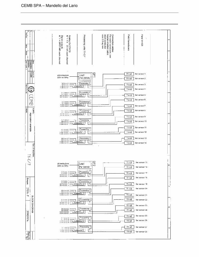
1. TECHNICAL DESCRIPTION OF THE SYSTEM
1.1. GENERAL
A seismic vibration transducer is installed on the housing for each fan according toany radial direction at random.The signal generated by the transducer is sent to an electronic processing unit.Connection is via a suitably sized shielded cable (up to 200 metres 2x1mm2 - up to400 metres 2x1.5mm2 - up to 800 metres 2x12.5m2 ).The processing unit is normally installed in the centre of gravity position withrespect to the tunnel section where the monitored fans are installed.
1.2. VIBRATION TRADUCERS
1.2.1. Type of transducer.The transducer is of the electrodynamic seismic type (velocity transducer), i.e.designed for measuring the speed of vibration parameters; there are no amplifyingor signal linearizing circuits incorporated in the transducer).
1.2.2. Frequency range.Frequency response of the transducer is linear in the range from 10 to 1000 Hz .
1.2.3. Temperature limits.The transducers should be able to operate correctly in the temperature range from– 10°C to + 100°C.
CEMB SPA – Mandello del Lario
1.2.4. Resistance to environmental agents.The transducer should be tightly sealed and insensitive to ambient humidity (max.25%) and resistance to contamination by dusts and lubricating oils with a degree ofprotection IP 65 (CEI standards)
1.2.5. Cables and connectors.The transducers are complete with male-female connection to MIL standards, ableto withstand the mechanical and thermal stresses described in points 1.2.3 and1.2.4.
1.2.6. Mounting.It should be possible to install the transducer in any direction and fasten it with asufficiently rugged screw (e.g. M8 thread).
TEST INSTRUMENTS
1.3.1. Types of instruments.All instruments are fully transistorized and the signal coming from a transducer issent to the respective conditioning and measuring circuit. The scanning system isnot permissible.
1.3.2. Measurement range.The instrument should allow measurement and supervision of the RMS value of thevibration speed within a range from 0 to 10 mm/s.
1.3.3. Frequency range.The instrument response is linear in a frequency range from 10 to 1000 Hz.
1.3.4. Threshold discriminator circuit.Each measuring channel is provided with a threshold discriminator circuit of statictype with amplitude comparator, suitable for driving an output relay (SPDT contact)and indicator lamp (LED).The tripping level of the alarm threshold is adjustable between 10% and 100% ofthe measuring scale.The alarm threshold is provided with a time delay device, independent from thevalue and adjustable from 0 to 20 seconds.The system output logic is as follows: under normal condition (vibration level belowthe threshold) the relay is de-energized and the LED is unlit. The alarm threshold isof the “unlatched” type, i.e. the output relay remains energized and the relative LEDis lit up only as long as the input signal is higher than the threshold value.

CEMB SPA – Mandello del Lario
1.3.5. Analog output.Each vibration channel sends an output signal 4 to 20 mA proportional to the RMSvalue of the vibration speed measured.
1.3.6. Environmental conditions.The instruments operate correctly within a temperature range from –10°C to +50°C.
1.3.7. Power supply.Instrument power supply is 220 Vac – 50 Hz
1.3.8. Composition of the instruments.Each instrument is mounted in a 19” rack enclosure able to process at least 16measuring channels. The following are installed in the unit:- one power supply complete with main switch- a number of signal processing boards which depend on the number of fans to be
monitored.

CEMB SPA – Mandello del Lario
POWER SUPPLY MODULE PW T1-C
FUNCTION
Power supply module PW T1-C is able to supply stabilized voltage up to 8 processingmodules T1-C. The power supply is mounted in a wall-mounted unit.The instrument can be mounted in suitable enclosure with degree of protection IP54 forapplications in protected environment.
TECHNICAL CHARACTERISTICS
External connections : terminal board WEIDMULLER TOP 1,5 GS
Supply voltage : 100 – 220 V 50 Hz ± 10%
Max. power consumption : 50 VA
Output voltages : + 15 V - 15 V
Max. output currents : + 15 V = 1 A- 15 V = 0.5 A
Unit : dwg. 23950
CEMB SPA – Mandello del Lario
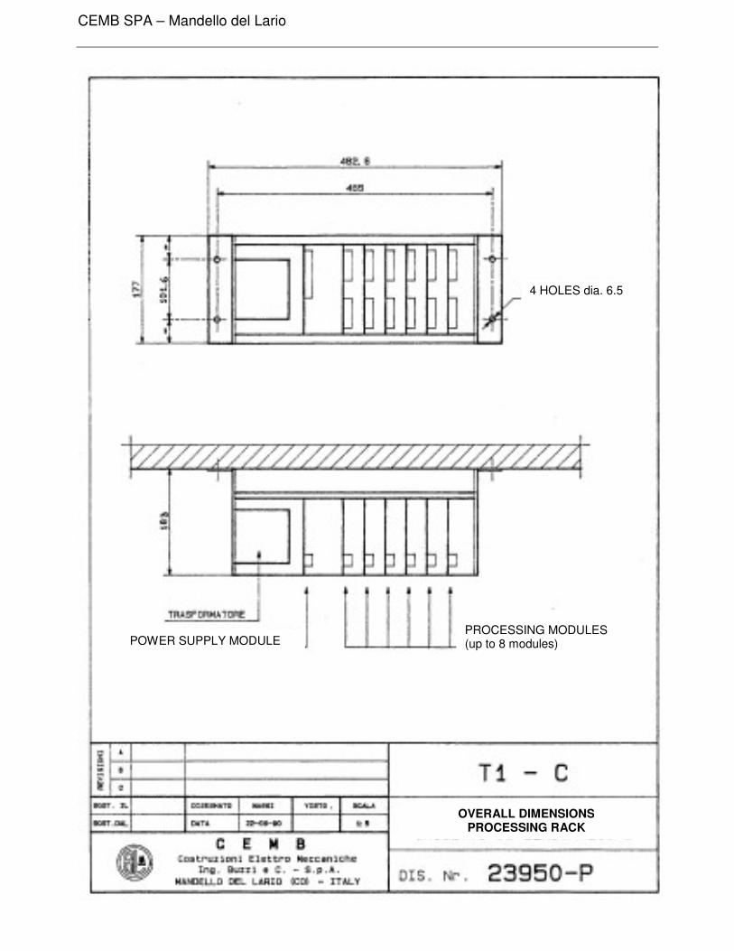
4 HOLES dia. 6.5
POWER SUPPLY MODULEPROCESSING MODULES(up to 8 modules)
OVERALL DIMENSIONSPROCESSING RACK
CEMB SPA – Mandello del Lario
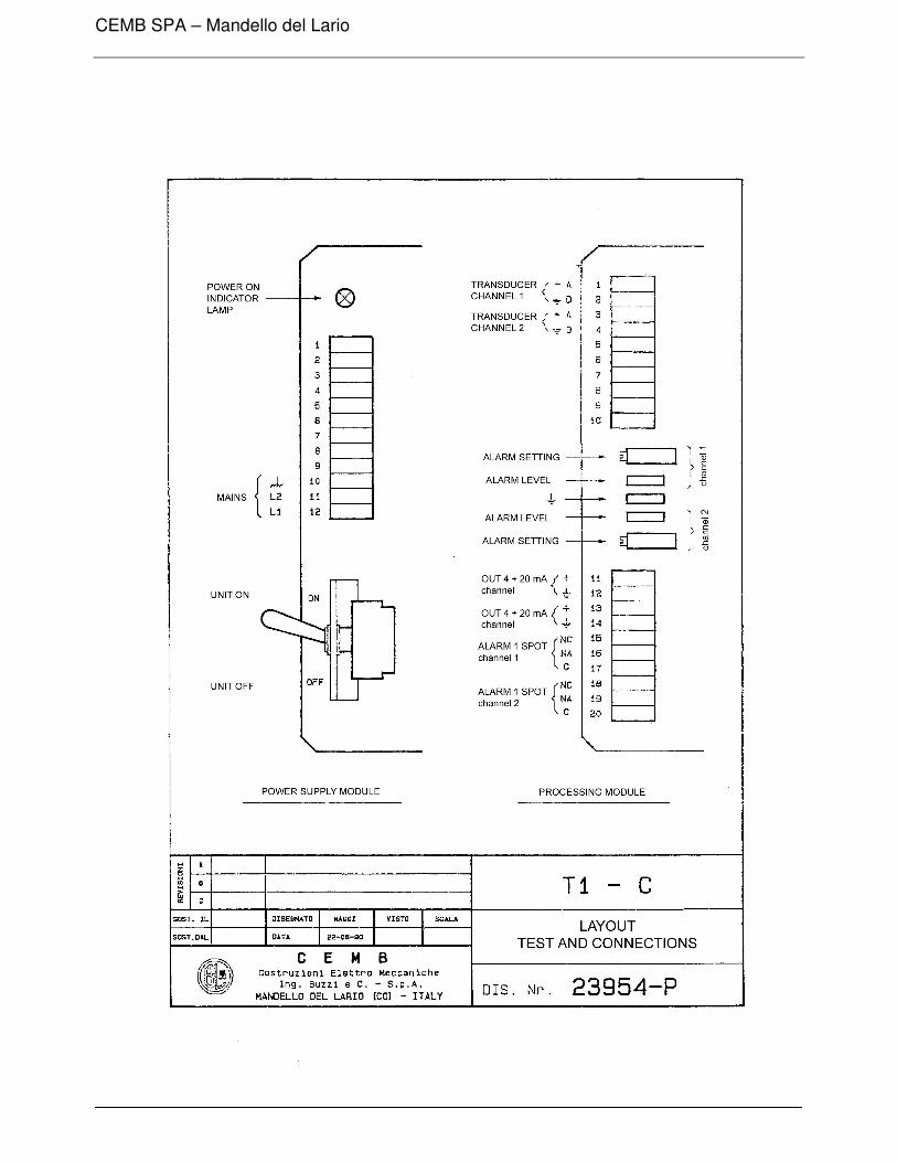
PROCESSING MODULE T1-C
FUNCTION
The T1-C processing module is able to process the signals coming from two vibrationtransducers type T1-40 and to supply, for each signal, an analog output and an alarmcontact. The module can supply the analog outputs proportional to the axial position orspeed of vibration.Such module is extremely compact in design while it allows simple and modular monitoringof the vibrations.
CEMB SPA – Mandello del Lario
TECHNICAL CHARACTERISTICS
External connections : terminal board WEIDMULLER TOP 1,5 GS
Supply voltage : + 15 V / - 15 V
Max. current drawn : + 15 V = 120 A- 15 V = 16 A:
N° of channels processed : 2
Unit of measurement of vibration : 0 to 100 µm, 0 to 300 µm 0 to 10 mm/sec 0 to 30 mm/sec
Output signals (terminalsOUT1 and OUT2) : 4 TO 20 mA proportional to the input vibration
Alarm contacts (terminalsALARM 1 – ALARM 2) : 1 SPDT for each channel
Max. current, alarm contacts : 3A
Max. voltage, alarm contacts : 250 V
Alarm adjustment : 0 to 100% of the measurement range
Alarm delay time : from 0 to 20 seconds (approx.)
Alarm condition indicator : Red LED located close to the alarm level setting potentiometer
CEMB SPA – Mandello del Lario
CEMB SPA – Mandello del Lario
capellim
Casella di testo
ASTA07120