Vibration measurement of electrical machines using integrated fibre … · · 2016-09-01Vibration...
4
Vibration measurement of electrical machines using integrated fibre Bragg gratings M. Fabian a* , J. Borg Bartolo b , M. Ams c , C. Gerada b , T. Sun a , K.T.V Grattan a a School Mathematics, Computer Science and Engineering, City University London, EC1V 0HB, UK; b Faculty of Engineering, University of Nottingham, University Park, Nottingham, UK; c Photonics Research Centre, Department of Physics & Astronomy, Faculty of Science and Engineering, MACQUARIE University, Sydney, Australia ABSTRACT In this paper a method to track the rotating force vector set up within the air-gap of radial flux rotating electrical machines using fibre Bragg gratings is reported. The proposed technique offers the potential for simultaneous rotor speed and position monitoring. This specific sensor design, together with other FBG-based multi-parameter measurements, is aimed to create an all-optical sensor solution for electrical machines, reducing the component count of existing systems and addressing noise issues traditionally associated with electrical sensors used. In this work, an optical fibre sensor system has been successfully integrated into an off-the-shelf four-pole 11kW induction motor. Keywords: Optical fibre sensor, fibre Bragg grating, rotational speed measurement, vibration sensor 1. INTRODUCTION To address the ever growing demand for new and reliable designs, electrical machines are increasingly required to be monitored in real-time with the data being used for both model validation and prototype diagnostics. Due to the relatively large size of conventional sensors, the resulting system might occupy a spatial envelope larger than the drive itself. Fibre Bragg grating (FBG)-based techniques have been reported to address the above challenges through the measurement of temperature 1 , torque 2 and stator end winding vibration 3 of electrical machines. In this work a novel approach is used in which the vibration measurement is extracted from an integrated sensor affixed to the machine’s stator bore as part of the development of an FBG-based rotational speed sensor which aims to establish an all-in- one fibre sensor system for electrical motor drives within an EU CleanSky framework. This builds solidly on the key advantages offered by FBG-based optical fibre sensors, including their immunity to electromagnetic interference, significantly reduced spatial envelope and their inherent multiplexing capabilities. The success of this work would also show promise for the rotor position measurement as discussed below. 2. PRINCIPLE OF OPERATION 2.1 Fibre Bragg Gratings An FBG formed within a fibre behaves like a ‘notch filter’ (in transmission), which reflects light at a wavelength termed the Bragg wavelength that satisfies the so-called Bragg condition 4 . The effects of temperature and strain on a grating’s Bragg wavelength have been widely reported 4 . In this work, the dynamic response of the FBG is recorded and it is associated with both the vibration of the stator to which the FBG is fixed on and the rotor speed. 2.2 Vibration monitoring in electrical machines using FBGs A considerable amount of effort has been applied to the analysis of vibratory signatures of electrical machines 5-7 , for the scope of noise reduction, and component condition monitoring 8 . The work presented in this paper focuses on the monitoring, (via the use of FBGs), of the vibratory response of the stator core of an induction machine as a function of the spatial modulation of the air-gap flux. Since the load-bearing structures in any iron-cored machine are the stator and rotor teeth, respectively, it was envisaged that the displacement of such structures with respect to * [email protected], phone 00442070400060; www.city.ac.uk
Transcript of Vibration measurement of electrical machines using integrated fibre … · · 2016-09-01Vibration...

Vibration measurement of electrical machines using integrated fibre Bragg gratings
M. Fabiana*
, J. Borg Bartolob, M. Ams
c, C. Gerada
b, T. Sun
a, K.T.V Grattan
a
aSchool Mathematics, Computer Science and Engineering, City University London, EC1V 0HB,
UK; bFaculty of Engineering, University of Nottingham, University Park, Nottingham, UK;
cPhotonics Research Centre, Department of Physics & Astronomy, Faculty of Science and
Engineering, MACQUARIE University, Sydney, Australia
ABSTRACT
In this paper a method to track the rotating force vector set up within the air-gap of radial flux rotating electrical machines using fibre Bragg gratings is reported. The proposed technique offers the potential for simultaneous rotor speed and position monitoring. This specific sensor design, together with other FBG-based multi-parameter measurements, is aimed to create an all-optical sensor solution for electrical machines, reducing the component count of existing systems and addressing noise issues traditionally associated with electrical sensors used. In this work, an optical fibre sensor system has been successfully integrated into an off-the-shelf four-pole 11kW induction motor.
Keywords: Optical fibre sensor, fibre Bragg grating, rotational speed measurement, vibration sensor
1. INTRODUCTION
To address the ever growing demand for new and reliable designs, electrical machines are increasingly required to be monitored in real-time with the data being used for both model validation and prototype diagnostics. Due to the relatively large size of conventional sensors, the resulting system might occupy a spatial envelope larger than the drive itself.
Fibre Bragg grating (FBG)-based techniques have been reported to address the above challenges through the
measurement of temperature1, torque
2 and stator end winding vibration
3 of electrical machines. In this work a novel
approach is used in which the vibration measurement is extracted from an integrated sensor affixed to the machine’s
stator bore as part of the development of an FBG-based rotational speed sensor which aims to establish an all-in-
one fibre sensor system for electrical motor drives within an EU CleanSky framework. This builds solidly on the
key advantages offered by FBG-based optical fibre sensors, including their immunity to electromagnetic
interference, significantly reduced spatial envelope and their inherent multiplexing capabilities. The success of this
work would also show promise for the rotor position measurement as discussed below.
2. PRINCIPLE OF OPERATION
2.1 Fibre Bragg Gratings
An FBG formed within a fibre behaves like a ‘notch filter’ (in transmission), which reflects light at a wavelength termed the Bragg wavelength that satisfies the so-called Bragg condition
4. The effects of temperature and strain on
a grating’s Bragg wavelength have been widely reported4. In this work, the dynamic response of the FBG is
recorded and it is associated with both the vibration of the stator to which the FBG is fixed on and the rotor speed.
2.2 Vibration monitoring in electrical machines using FBGs
A considerable amount of effort has been applied to the analysis of vibratory signatures of electrical machines5-7
, for the scope of noise reduction, and component condition monitoring
8. The work presented in this paper focuses
on the monitoring, (via the use of FBGs), of the vibratory response of the stator core of an induction machine as a function of the spatial modulation of the air-gap flux. Since the load-bearing structures in any iron-cored machine are the stator and rotor teeth, respectively, it was envisaged that the displacement of such structures with respect to
* [email protected], phone 00442070400060; www.city.ac.uk
each other should provide some insight into the speed or position of the main/torque inducing flux field. This concept is illustrated analytically by considering Maxwell’s stress tensor (MST) assuming that magnetic flux enters and exits the surface of interest normally such that the radial component of field strength is much higher than the tangential one, responsible for torque production. Thus, the normal component of the experienced stress on the stator teeth, σn(ϑm,t), can be expressed in terms of the normal air gap flux density distribution, Bn(ϑm,t), as
5,9:
o
mnmn
tBt
µϑ
ϑσ2
),(),(
2
≈ (1)
where ϑm is the mechanical angular position along the stator bore perimeter from a given datum and µo is the permeability of free space. If the air gap is constant (no eccentricities) an expression for the stress normal to the air-gap surface can be deduced as:
[ ]
++≈ )).(2cos(1
22
1),(
2
mpes
o
mn ptB
t ϑωµ
ϑσ (2)
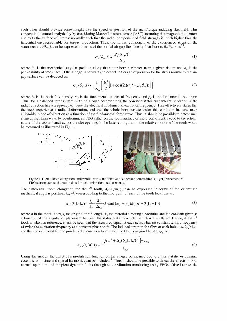
where Bs is the peak flux density, ωe is the fundamental electrical frequency and pp is the fundamental pole pair. Thus, for a balanced rotor system, with no air-gap eccentricities, the observed stator fundamental vibration in the radial direction has a frequency of twice the electrical fundamental excitation frequency. This effectively states that the teeth experience a radial deformation, and that the whole bore surface under this condition has one main ellipsoidal mode of vibration as a function of the fundamental force wave. Thus, it should be possible to detect such a travelling strain wave by positioning an FBG either on the tooth surface or more conveniently (due to the retrofit nature of the task at hand) across the slot opening. In the latter configuration the relative motion of the tooth would be measured as illustrated in Fig. 1.
Figure 1. (Left) Tooth elongation under radial stress and relative FBG sensor deformation; (Right) Placement of FBG sensors across the stator slots for strain/vibration measurements.
The differential tooth elongation for the nth
tooth, ∆n(ϑm[n],t), can be expressed in terms of the discretised mechanical angular position, ϑm[n], corresponding to the mid-point of each of the tooth locations as:
]))1[][(2sin(2
)],[(2
−++⋅⋅⋅=∆ nnptkB
E
ltn mmpe
o
s
t
t
mn ϑϑωµ
ϑ (3)
where n in the tooth index, lt the original tooth length, Et the material’s Young’s Modulus and k a constant given as a function of the angular displacement between the stator teeth to which the FBGs are affixed. Hence, if the n
th
tooth is taken as reference, it can be seen that the measured signal at each sensor has no constant term, a frequency of twice the excitation frequency and constant phase shift. The induced strain in the fibre at each index, εf (ϑm[n],t), can then be expressed for the purely radial case as a function of the FBG’s original length, lfbg, as:
fbg
fbgmn
mfl
ltnl
tnfbg −
∆+
=
22)],[(
)],[(
ϑϑε (4)
Using this model, the effect of a modulation function on the air-gap permeance due to either a static or dynamic eccentricity or time and spatial harmonics
can be included
8. Thus, it should be possible to detect the effects of both
normal operation and incipient dynamic faults through stator vibration monitoring using FBGs affixed across the

stator tooth opening. It can be shown8 for the
eccentricity-only case, that in addition to the components given in
equations (2) and (4) the dynamic eccentricity condition introduces additional vibrations at the frequencies ωr and 2ωr and at 2ωe±ωr and 2(ωe±ωr). Note that for the case of a rotor having an imbalance, a dynamic eccentricity effect is present at the air gap, as well as a mechanical ‘synchronous excitation’ of the rotor body, thus the ωr term would be present in the measured vibration spectrum due to both air gap field modulation and mechanical imbalance).
3. EXPERIMENTAL SETUP
3.1 Sensor fabrication and instrumentation
The FBGs used in this study were manufactured using the phase mask technique. The photosensitive fibre (Fibercore SM1500) was illuminated using an ATLEX 300-SI laser at 248 nm. The gratings were recoated
(Fujikura FSR-02) to re-establish mechanical stability and annealed at 180°C for approximately four hours.
3.2 Sensor integration into the electrical machine
The electrical machine chosen for this investigation is a 4-pole, three-phase, 11 kW machine with 36 stator slots and 28 rotor bars. An optical fibre with 16 FBGs written into it was installed along the machine’s bores with the FBGs placed across every other stator slot spanning from one tooth to the next as shown in Fig. 1. The fibre was affixed using a two-component, epoxy based, glue system from Araldite capable of withstanding up to 90˚C.
3.3 Data acquisition and signal processing
The dynamic Bragg wavelength shifts of all FBGs were captured simultaneously using a Micron Optics SM130-700 sensing interrogator unit, at a sampling rate of 1000 Hz. The DC components of the transient signals were used for thermal analysis (beyond the scope of this paper) whereas the AC components were used to determine stator vibrations in order to determine the rotor speed. For the chosen sampling interval of 5 seconds, the frequency resolution is 0.2 Hz.
4. RESULTS
The machine was first spun under no load. The fundamental electrical frequency was chosen to be 40Hz and the machine was driven by a Chroma 61705 sinusoidal power supply. Fig. 2 shows the frequency responses of two FBGs placed 13 slots apart as well as the spectral features obtained with a conventional vibration monitoring instrument (SKF Mircolog GX analyser).
Figure 2. (Left) Frequency response spectra of two FBGs placed 23 slots apart from one another. (Right) Frequency spectrum obtained with an off-the-shelf accelerometer.
It is clear from Fig. 2 that the results of both methods are in good agreement, with the FBG successfully detecting the major vibration components at 20, 40, 60 and 80 Hz. Considering the low slip conditions under no load, it is safe to conclude that the rotation frequency of the shaft is very close to the synchronous frequency at 20 Hz, and thus the measured harmonics can be labelled as in Fig. 2 in accordance with the theory presented in section 2.2.
Fig. 3(a) shows the time domain Bragg-wavelength shifts of the two aforementioned FBGs indicating a phase shift between them. This is a very promising result which strongly suggests that this method might be used not only for vibration/speed monitoring but also for positional tracking of the force wave in the stator.

Following the no-load test, the rotor was locked (maximum load) and the frequency responses of a random FBG are shown in Fig. 3(b) for two phase currents (8.7 A and 14 A, the latter being the machine’s rated current). As expected, the main frequency component for this operating condition (the rotor being static, no dynamic air-gap modulation), is twice the fundamental frequency, i.e., 80Hz.
Figure 3. (a) Bragg wavelength shifts of the corresponding frequency spectra of the two sensors in Fig. 2; (b) Frequency response spectra of a random FBG for the locked rotor case at different phase currents: (1) 8.7 A and (2) 14 A. The different feature strengths in the sensor responses are due to a different slot displacement magnitude for the two loading conditions
5. CONCLUSION
It was shown that fibre Bragg gratings are capable of tracking the fundamental force wave travelling along a stator bore of an electrical machine when placed in between the machine’s stator teeth. It is therefore possible to monitor the rotor speed based on the stator vibration signature and potentially to extract the force vector position for the control of induction machines drives. The obtained results are encouraging, indicating that the considered technology offers great potential for all-optical condition monitoring of electrical machines.
ACKNOWLEDGMENTS
The authors wish to thank the EU CleanSky Initiative and the Worshipful Company of Tin Plate Workers in the UK for the financial support for this investigation.
REFERENCES
[1] De Morais Sousa, K., Hafner, A. A. and Kalinowski, H. J., “Determination of temperature dynamics and mechanical and stator losses relationships in a three-phase induction motor using fiber bragg grating sensors”, IEEE Sensors Journal 12(10), 3054-3061, (2012).
[2] Swart, P. L., Chtcherbakov, A. A. and van Wyk, A. J., “Dual bragg grating sensor for concurrent torsion and temperature measurement”, Meas. Sci. Technol. 17, 1057-1064, (2006).
[3] Sasic, M., Jiang, H. and Stone, G. C., “Requirements for Fiber Optic Sensors for Stator Endwinding Vibration Monitoring”, Proc. IEEE International Conference on Condition Monitoring and Diagnosis B-1, 118-121, (2012).
[4] Rao, Y.-J., “In-fibre bragg grating sensors”, Meas. Sci. Technol. 8(4), 355-375, (1997).
[5] Schlensok, C., Van der Giet, M., Herranz Gracia, M.,Van Riesen, D. and Hameyer, K., “Structure-Dynamic Analysis of an Induction Machine Depending on Stator–Housing Coupling”, IEEE Trans. on Industry Applications 44(3), 753-759, (2008).
[6] Valavi, M., Nysveen, A., Nilssen, R. and Rølvåg T., “Slot Harmonic Effect on Magnetic Forces and Vibration in Low-Speed Permanent Magnet Machine with Concentrated Windings”, IEEE Trans. on Industry Applications 50(5), 3304-3313, (2014).
[7] Immovilli, F., Bellini, A., Rubini, R. and Tassoni, C., “Diagnosis of Bearing Faults in Induction Machines by Vibration or Current Signals: A Critical Comparison”, IEEE Trans. on Industry Applications 46(4), 1350-1359, (2010).
[8] Arellano-Padilla, J., Sumner, M. and Gerada, C., “Winding conditon monitoring scheme for a permanent magnet machine using high-frequency injection”, IET Electrical Power Applications 5(1), 89-99, (2011).
[9] Rodriguez, P. V. J., Belahcen, A., Arkkio, A. and Antonino-Daviu, J. A., “Air-gap force distribution and vibration pattern of indcution motors under dynamic eccentricity”, Springer Electr. Eng. 90(3), 209-218, (2008).