vibration harvesting in railway tunnels v2.0cap.ee.ic.ac.uk/~pdm97/powermems/2010/oral-pdfs/... ·...
4
VIBRATION HARVESTING IN RAILWAY TUNNELS M. Wischke * , G. Biancuzzi, G. Fehrenbach, Y. Abbas, P. Woias Laboratory for Design of Microsystems, University of Freiburg – IMTEK, Germany *Presenting Author: [email protected] Abstract: We report on the vibration characteristics, and a piezoelectric generator for harvesting electrical energy to power wireless sensor nodes, inside railway tunnels. Extensive investigations have shown that the railway sleeper is favorable for placing a vibration harvester concerning vibration levels and mounting space. A shock resistant double-side suspended piezoelectric harvester has been tested with true train vibrations. In average 260 μWs have been scavenged per train, which is sufficient energy for simple wireless communication. To avoid a deadlock of the sensor node, we have designed a new ultra low power interface circuit. Keywords: vibration harvesting, railway tunnels, piezoelectric INTRODUCTION The structural integrity of traffic tunnels after harmful incidents is a decisive factor for all further measures, e.g. the dispatch of rescue forces. It would be extremely helpful to retrieve on-site information on the status of the building via a distributed sensor system [1]. However, a full-scale monitoring of civil underground infrastructure requires a large number of embedded sensors [2]. Equipping a tunnel with a monitoring sensor grid requires a large effort due to the hardly accessible location. Thereby, the sensor nodes might be embedded completely into the host structure, so that no wired connection is possible. Scavenging ambient energy to charge or replace built- in batteries [3] opens up the application of autonomous wireless sensors in such remote locations. In addition to the alternative power supply an extremely economic handling of the available energy is indispensible. Modern ICs and MCUs can operate with voltages down to 1.8 V. Nevertheless when the supply voltage drops down to the threshold range, CMOS devices are draining uncontrolled current. Thereby, the power consumption can exceed the generators output and the system becomes deadlocked. Hence, a faultless start from 0 V is required. To address the demand on structural health monitoring (SHM) of traffic tunnels, we have investigated the traffic induced vibrations as an alternative power source. For scavenging the electrical energy, a robust piezoelectric generator is utilized. Equipped with a novel power interface the presented power unit can operate from 0 V. VIBRATION IN TUNNELS Tunnels are frequently the bottlenecks in transportation infrastructure and therefore very busy. Thus, they are hardly accessible for measurements and the systematic characterization of numerous tunnels is almost impossible. The vibrations in two railway tunnels have been investigated for the purpose as alternative power source. A brief introduction of the tunnels is given and Table 1 summarizes their main features. Arlberg-Tunnel The Arlberg railway tunnel is an old and historic building. It is situated between Klösterle and St. Anton am Arlberg in Austria and operated by the Austrian rail agency (ÖBB). Lötschbergbasis-Tunnel The Lötschbergbasis-Tunnel is the youngest long distance and high speed tunnel in Europe and connects Frutigen with Raron in Switzerland. The tunnel is operated by the BLS AG. Tab. 1: Details of the investigated tunnels. Arlberg Lötschbergbasis Length 10.65 km 34.56 km Completion 1884 2007 Walls Natural stones Concrete Tracks Ballast, fixed track Fixed track Traffic 2 rails, opposing Partial alternating Speed Limit 100 km/h 200 km/h Traffic volume 70-90 trains/day 80-110 trains/day Of major interest for micro-generators is the rate of vertical acceleration induced by passing trains to the rail track or deck, and the propagation of the vibration to the tunnel walls. Acceleration sensors from Kistler (8704B-series and 8636C5) were mounted to the rail, the sleeper, the base and the tunnel wall. Fig. 1: Acceleration sensors mounted at the track in the Lötschbergbasis-Tunnel.
Transcript of vibration harvesting in railway tunnels v2.0cap.ee.ic.ac.uk/~pdm97/powermems/2010/oral-pdfs/... ·...

VIBRATION HARVESTING IN RAILWAY TUNNELS
M. Wischke*, G. Biancuzzi, G. Fehrenbach, Y. Abbas, P. Woias Laboratory for Design of Microsystems, University of Freiburg – IMTEK, Germany
*Presenting Author: [email protected] Abstract: We report on the vibration characteristics, and a piezoelectric generator for harvesting electrical energy to power wireless sensor nodes, inside railway tunnels. Extensive investigations have shown that the railway sleeper is favorable for placing a vibration harvester concerning vibration levels and mounting space. A shock resistant double-side suspended piezoelectric harvester has been tested with true train vibrations. In average 260 µWs have been scavenged per train, which is sufficient energy for simple wireless communication. To avoid a deadlock of the sensor node, we have designed a new ultra low power interface circuit. Keywords: vibration harvesting, railway tunnels, piezoelectric INTRODUCTION
The structural integrity of traffic tunnels after harmful incidents is a decisive factor for all further measures, e.g. the dispatch of rescue forces. It would be extremely helpful to retrieve on-site information on the status of the building via a distributed sensor system [1]. However, a full-scale monitoring of civil underground infrastructure requires a large number of embedded sensors [2]. Equipping a tunnel with a monitoring sensor grid requires a large effort due to the hardly accessible location. Thereby, the sensor nodes might be embedded completely into the host structure, so that no wired connection is possible. Scavenging ambient energy to charge or replace built-in batteries [3] opens up the application of autonomous wireless sensors in such remote locations.
In addition to the alternative power supply an extremely economic handling of the available energy is indispensible. Modern ICs and MCUs can operate with voltages down to 1.8 V. Nevertheless when the supply voltage drops down to the threshold range, CMOS devices are draining uncontrolled current. Thereby, the power consumption can exceed the generators output and the system becomes deadlocked. Hence, a faultless start from 0 V is required.
To address the demand on structural health monitoring (SHM) of traffic tunnels, we have investigated the traffic induced vibrations as an alternative power source. For scavenging the electrical energy, a robust piezoelectric generator is utilized. Equipped with a novel power interface the presented power unit can operate from 0 V. VIBRATION IN TUNNELS
Tunnels are frequently the bottlenecks in transportation infrastructure and therefore very busy. Thus, they are hardly accessible for measurements and the systematic characterization of numerous tunnels is almost impossible. The vibrations in two railway tunnels have been investigated for the purpose as alternative power source. A brief introduction of the tunnels is given and Table 1 summarizes their main features.
Arlberg-Tunnel The Arlberg railway tunnel is an old and historic
building. It is situated between Klösterle and St. Anton am Arlberg in Austria and operated by the Austrian rail agency (ÖBB).
Lötschbergbasis-Tunnel The Lötschbergbasis-Tunnel is the youngest long
distance and high speed tunnel in Europe and connects Frutigen with Raron in Switzerland. The tunnel is operated by the BLS AG.
Tab. 1: Details of the investigated tunnels.
Arlberg Lötschbergbasis
Length 10.65 km 34.56 km Completion 1884 2007 Walls Natural stones Concrete Tracks Ballast, fixed track Fixed track Traffic 2 rails, opposing Partial alternating Speed Limit 100 km/h 200 km/h Traffic volume 70-90 trains/day 80-110 trains/day
Of major interest for micro-generators is the rate of vertical acceleration induced by passing trains to the rail track or deck, and the propagation of the vibration to the tunnel walls. Acceleration sensors from Kistler (8704B-series and 8636C5) were mounted to the rail, the sleeper, the base and the tunnel wall.
Fig. 1: Acceleration sensors mounted at the track in the Lötschbergbasis-Tunnel.
The AC signals were recorded with a DT9836 module from Data Translation, featuring simultaneous 16-bit resolution at 225 kHz per channel. In the railroad tunnel, a sensor mounted at the rail was used as a trigger to start the data recording. Thus, each passing train was detected individually. The overall detection period in each tunnel was in range of 20-24 h and the induced vibrations of approx. 70 trains were recorded respectively. Figure 1 shows the acceleration sensors on the railway track in the Lötschbergbasis-Tunnel.
Fig. 2: Acceleration of the railway sleeper in the Arlberg-Tunnel during the passage of a freight train.
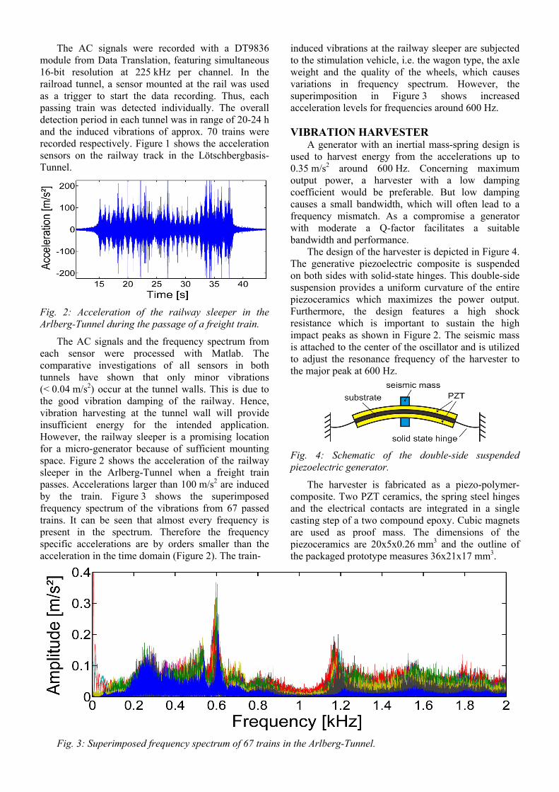
The AC signals and the frequency spectrum from each sensor were processed with Matlab. The comparative investigations of all sensors in both tunnels have shown that only minor vibrations (< 0.04 m/s2) occur at the tunnel walls. This is due to the good vibration damping of the railway. Hence, vibration harvesting at the tunnel wall will provide insufficient energy for the intended application. However, the railway sleeper is a promising location for a micro-generator because of sufficient mounting space. Figure 2 shows the acceleration of the railway sleeper in the Arlberg-Tunnel when a freight train passes. Accelerations larger than 100 m/s2 are induced by the train. Figure 3 shows the superimposed frequency spectrum of the vibrations from 67 passed trains. It can be seen that almost every frequency is present in the spectrum. Therefore the frequency specific accelerations are by orders smaller than the acceleration in the time domain (Figure 2). The train-
induced vibrations at the railway sleeper are subjected to the stimulation vehicle, i.e. the wagon type, the axle weight and the quality of the wheels, which causes variations in frequency spectrum. However, the superimposition in Figure 3 shows increased acceleration levels for frequencies around 600 Hz. VIBRATION HARVESTER
A generator with an inertial mass-spring design is used to harvest energy from the accelerations up to 0.35 m/s2 around 600 Hz. Concerning maximum output power, a harvester with a low damping coefficient would be preferable. But low damping causes a small bandwidth, which will often lead to a frequency mismatch. As a compromise a generator with moderate a Q-factor facilitates a suitable bandwidth and performance.
The design of the harvester is depicted in Figure 4. The generative piezoelectric composite is suspended on both sides with solid-state hinges. This double-side suspension provides a uniform curvature of the entire piezoceramics which maximizes the power output. Furthermore, the design features a high shock resistance which is important to sustain the high impact peaks as shown in Figure 2. The seismic mass is attached to the center of the oscillator and is utilized to adjust the resonance frequency of the harvester to the major peak at 600 Hz.
Fig. 4: Schematic of the double-side suspended piezoelectric generator.
The harvester is fabricated as a piezo-polymer-composite. Two PZT ceramics, the spring steel hinges and the electrical contacts are integrated in a single casting step of a two compound epoxy. Cubic magnets are used as proof mass. The dimensions of the piezoceramics are 20x5x0.26 mm3 and the outline of the packaged prototype measures 36x21x17 mm3.
Fig. 3: Superimposed frequency spectrum of 67 trains in the Arlberg-Tunnel.

The harvester was characterized in the lab with an electromagnetic shaker. Under sinusoidal excitation with 10 m/s2 up to 300 µW are scavenged at resonance with optimal load resistance [4]. Figure 5 shows the harvester mounted onto the test rig.
Fig. 5: Packaged harvester on the test rig.
To test the applicability the recorded acceleration of the railway sleeper from the measurements in the tunnels were played back on the shaker. A diode bridge rectifier and a storage capacitor were connected to the harvester and the capacitor voltage was monitored. Figure 6 shows the overlay of the sleeper vibration and the capacitor voltage for a single train passage. It can be seen, that the voltage increases stepwise at the high vibration peaks.
Fig. 6: Charging of the storage capacitor from a single train passage from the Arlberg-Tunnel.
As mentioned before, each train induces slightly different vibrations to the railway sleeper, which affects the charging curve. Hence the measurements were repeated for 20 different trains from the Arlberg-Tunnel. The results are shown in Figure 7.
Fig. 7: Charging curves of the storage capacitor for 20 different trains from the Arlberg-Tunnel.
For the majority of the 20 trains, the capacitor voltage raises above the 2 V, which is a critical level to operate CMOS ICs. The stored electrical energy in the capacitor voltage for this test is shown in Figure 8. In average 260µWs have been scavenged per train. With a low voltage design this is sufficient energy for a simple wireless sensor node as demonstrated in [5].
Fig. 8: Stored energy in the capacitor for 20 different trains from the Arlberg-Tunnel. POWER MANAGEMENT Utilizing ambient vibrations to power an electrical system requires a power processing and an economical handling of the available energy. For rectification of the AC voltage from the piezoceramics a trade-off between the threshold voltage and the leakage current of the diodes has to be made. A good choice are the Schottky diodes HSMS-282x [6]. The charge from the generator is collected in a storage capacitor of 100 µF.
Modern sensor and RF ICs are throughout fabricated in CMOS technology. Hence they need a certain supply voltage for proper operation. When the supply voltage drops below the threshold voltage uncontrolled states occur and CMOS electronics drain much higher currents than under normal operation. If the CMOS devices are connected directly to the storage capacitor this phenomena can deadlock the whole sensor node when the sub-threshold current exceeds the generator performance. Therefore the sensor electronic has to stay disconnected from the storage until the voltage reaches a suitable level. Due to the energy consumption of the sensor electronics the capacitor voltage will decrease. To enable the extraction of energy from the storage capacitor for powering the sensor, the load switch has to feature an “off” voltage lower than the “on” voltage. Further, the supply voltage for the CMOS electronics should be kept constant. Figure 9 shows the block diagram of the used power interface.
Fig. 9: Block diagram of the power interface.

For the energy autonomous operation, it is also mandatory that the power switch operates properly from 0 V (empty storage capacitor) and for the reason of energy conservation the leakage current has to be very low.
We have designed a power switch circuit that combines the voltage detection and the switching function. For the preliminary test the “on”-voltage was set to 2.4 V and the “off” voltage of 1.9 V respectively. The power switch consumes less than 100 nA at 2 V. The output voltage is set to 1.8 V by a voltage regulator (LDO) from Torex [7]. In total, the power interface consumes less than 3 µW and guarantees the recommended operation condition for CMOS sensor and RF circuit. DISCUSSION
The train-induced vibrations inside railway tunnels were explored by acceleration measurements. High accelerations occur at the railway track when a train passes (see Figure 2), while the tunnel wall remains almost unaffected. The frequency spectrum in Figure 3 shows the ambient character of the vibrations: various frequencies, but with low acceleration levels. Around 600 Hz higher vibration levels are found. This peak is specific for the fixed track Arlberg-Tunnel. The frequency spectrum from the Lötschbergbasis-Tunnel looks different and also higher vibrations levels are found at other frequencies. Each tunnel and track has an individual frequency spectrum so that the resonance frequency of a harvester always has to be adjusted by the size of the seismic mass respectively. Furthermore, each train shows a slightly different frequency spectrum and frequencies with maximum acceleration levels.
From the ambient character, the following challenging demands on the harvester are obtained: the design must feature a suitable bandwidth to respond to the vibration of each train and the design must be robust to sustain the impact accelerations of more than 100 m/s2. The double-side suspension of our harvester (Figure 4) ensures the required shock resistance. The harvester was fabricated in a low cost technology by manual insert casting. The top cover of the package (see Figure 5) is a PCB board which will carry the currently remote power interface circuit in future. Thus a more compact size will be achieved. Figure 6 shows that the storage capacitor can be charged to a suitable voltage level from true train vibrations. The stepwise charging indicates that only at the high vibration peaks the harvester is operating temporarily at resonance. For a more continuous operation either the bandwidth of the harvester has to be increased or a resonator array has to be utilized. However, Figure 7 and Figure 8 proof, that with the current design enough energy to power a simple wireless sensor can be scavenged from the train vibration.
To minimize the losses of the scavenged energy we have carefully selected the electrical components. Low leakage, low threshold diodes were chosen for the bridge rectifier. Even more important is the use of a power interface that avoids the energy consumption by malfunction of any sensor node component. By merging the voltage detection and the load switch in one circuit, the power consumption was reduced drastically. With its hysteresis and the capability to start from 0 V, our power interface fits excellent all the demands of a link between the harvester and the sensor node electronics. CONCLUSION
The presented PEG and the power interface form a smart unit that can directly supply wireless sensor nodes from traffic caused vibrations in railway tunnels. A promising application is high resolution localization of the train inside the tunnel.
OUTLOOK Future work is focused on the increase of the harvester’s bandwidth and the integration of the sensor and RF circuit into the harvester package and the application in the railway tunnel.
ACKNOWLEDGEMENTS
The authors would like to thank Mr. Spiss (ÖBB) and Mr. Hartleitner (ÖBB), and Mr. Stadelmann (BLS AG) for the access to the tunnels and the awesome cooperation.
This work is part of AISIS, funded by the BMBF in the high-tech strategy for protection of transportation infrastructure. REFERENCES [1] Li M, Liu Y 2007 Underground structure monitoring with wireless sensor networks Proc. of IPSN 07 69-78. [2] Bhalla S, Yang Y W, Zhao J, Soh C K 2005 Structural health monitoring of underground facilies – Technological issues and challenges Tunnelling Underground Space Technol. 20 487-500. [3] Roundy S, Wright P K, Rabaey J 2003 A study of low level vibrations as power source for wireless sensor nodes Computer Commun. 26 1131-1144. [4] Wischke M, Masur M, Goldschmidtboeing F, Woias P 2008 A hybrid generator for vibration energy harvesting applications Digest Tech. Paper of Transducer 09 521-524. [5] Woias P, Wischke M, Eichhorn C, Fuchs B 2009 An energy-autonomous wireless temperature monitoring system powered by piezoelectric energy harvesting Proc. of PowerMEMS 09 209-212. [6] www.agilent.com [7] www.torex-usa.com