
Vibration guideline for large diesel engines
42
Vibration guideline for large diesel engines Johannes Örn Bachelor’s thesis Mechanical and production engineering Vaasa 2014
-
Upload
nguyennguyet -
Category
Documents
-
view
243 -
download
2
Transcript of Vibration guideline for large diesel engines
Vibration guideline for large diesel engines Johannes Örn Bachelor’s thesis Mechanical and production engineering Vaasa 2014
BACHELOR’S THESIS
Author: Johannes Örn
Degree Programme: Mechanical and Production Engineering, Vaasa
Specialization: Mechanical Construction Systems
Supervisors: Kaj Rintanen & Kari Saine
Title: Vibration guideline for large diesel engines
_____________________________________________________________________
Date: 3.4.2014 Number of pages: 33 Appendices: 2
_____________________________________________________________________
Summary
This thesis was written at Wärtsilä’s engine factory in Vaasa. Wärtsilä has had
several different guidelines for measuring vibrations and acceptable levels of
vibration on their 20, 32 and 34 engine series. The purpose of this thesis was to
locate and summarize these guidelines in one coherent text. Measurement data
from vibration measurements conducted over the years was also put into one
excel file.
The beginning of the thesis consists of basic vibration theory. Then the thesis
deals with more advanced vibration theory needed when performing and
analyzing vibration measurements. One chapter includes an overview of the gear
that Wärtsilä uses. Vibration tests of different mechanical and electrical
components mounted on the Wärtsilä engines are also presented.
The new guidelines need to be in agreement with valid standards from the
classification societies and this was taken into consideration. But it was found out
that some of the standards could not be used with Wärtsilä’s guidelines. In some
test procedures Wärtsilä will create a standard of their own that is stricter than
the one given by the classification societies.
In the end a guideline with acceptable levels of vibration and ways of measuring
vibration on not only Wärtsilä’s engines but also on other large diesel engines was
presented.
_____________________________________________________________________
Language: English Key words: vibration, guideline, standards
_____________________________________________________________________
Filed at Theseus.fi
OPINNÄYTETYÖ
Tekijä: Johannes Örn
Koulutusohjelma ja paikkakunta: Kone- ja tuotantotekniikka, Vaasa
Suuntautumisvaihtoehto: Koneensuunnittelu
Ohjaajat: Kaj Rintanen & Kari Saine
Nimike: Isojen dieselinmoottorien värähdysohje
_____________________________________________________________________
Päivämäärä: 3.4.2014 Sivumäärä: 33 Liitteet: 2
_____________________________________________________________________
Tiivistelmä
Opinnäytetyö tehtiin Wärtsilässä Vaasan tehtaassa. Syy opinnäytetyöhön oli, että
Wärtsilällä oli monia eri ohjeita värähdysmittaukseen ja sallittuja värähdystasoja
heidän 20, 32 ja 34-moottorisarjaan. Työni oli kerätä ja tiivistää näitä ohjeita
yhteen tekstiin. Keräsin myös mittausdataa värähtelymittauksista monelta
vuodelta ja laitoin niitä Excel-tiedostoon.
Aloitin kirjoittamalla helposta värähdysteoriasta saadakseni sitä mukaan
ohjeeseen. Sen jälkeen otin mukaan enemmän pitkälle kehittynyttä
värähdysteoriaa, jota tarvitaan, kun tehdään ja analysoidaan värähdysmittauksia.
Saadakseen yleiskuvan koneelle, mitä Wärtsilä käyttää värähdysmittauksissa
esitän niitä yhdessä luvussa. Wärtsilän moottoriin asennettuja mekaanisia ja
sähköisiä komponentteja, joita on värähdystestattu esitellään myöskin.
Uudet ohjeet pitää olla yhteisymmärryksessä voimassa olevien standardien
kanssa, joka otettiin huomioon. Todettiin, että osa näistä standardeista ei voida
käyttää Wärtsilän ohjeiden kanssa. Joissakin testeissä Wärtsilä tekee omat
tarkemmat standardit kuin standardiseura.
Lopussa ohje, missä löytyy sallittuja värähdystasoja ja menettelytapoja tehdä
värähdysmittauksia Wärtsilän moottoreihin, mutta myöskin muihin isoihin
dieselmoottoreihin.
_____________________________________________________________________
Kieli: Englanti Avainsanat: Värähdykset, ohje, standardi
_____________________________________________________________________
Opinnäytetyö arkistoidaan verkkokirjastossa Theseus.fi
EXAMENSARBETE
Författare: Johannes Örn
Utbildningsprogram och ort: Maskin- och produktionsteknik, Vasa
Inriktningsalternativ: Maskinkonstruktion
Handledare: Kaj Rintanen & Kari Saine
Titel: Vibrationsriktlinje för stora dieselmotorer
_____________________________________________________________________
Datum: 3.4.2014 Sidantal: 33 Bilagor: 2
_____________________________________________________________________
Abstrakt
Jag gjorde detta examensarbete åt Wärtsiläs fabrik i Vasa. Bakgrunden till arbetet
var att Wärtsilä hade flera olika riktlinjer för vibrationsmätningar och acceptabla
vibrationsnivåer på deras 20, 32 och 34 motorserie. Mitt arbete gick ut på att
samla ihop dessa riktlinjer och sammanfatta dessa till en sammanhängande text.
Jag samlade även ihop mätdata från vibrationsmätningar som genomförts under
många år och samlade dessa i en Excel-fil.
Jag tog avstamp i enkel vibrationsteori för att få med grunderna i riktlinjen. Efter
detta gick gick jag in på mera avancerad vibrationsteori, som behövs när man gör
och analyserar vibrationsmätningar. Utrustningen som används av Wärtsilä togs
upp i ett kapitel för att få en överblick av denna. Vibrationstest av olika
mekaniska och elektriska komponenter som monteras på Wärtsiläs motorer
presenteras även.
De nya riktlinjerna behöver vara i samförstånd med gällande standarder från
klassificeringssällskapen och togs därför i beaktande. Dock konstaterades att en
del av standarderna inte kunde användas i enlighet med Wärtsiläs riktlinjer. Vid
en del testprocedurer kommer Wärtsilä att göra en egen strängare standard än
den från klassificeringssällskapet.
I slutändan åstadkoms en riktlinje med acceptabla vibrationsnivåer samt förslag
till mätning av vibrationer för Wärtsiläs motorer, men även för stora dieselmotorer
överlag.
_____________________________________________________________________
Språk: engelska Nyckelord: vibrationer, riktlinjer, standard
_____________________________________________________________________
Examensarbetet förvaras i webbiblioteket Theseus.fi
Table of contents
1 Introduction ..................................................................................................................... 1
1.1 Wärtsilä ....................................................................................................................... 1
1.2 Problem definition and goal ....................................................................................... 1
1.3 Limitations ....................................................................................................................... 2
1.4 Outline ........................................................................................................................ 2
2 Basic vibration theory .................................................................................................... 3
2.1 Basic theory ............................................................................................................... 4
2.2 Vibration parameters ................................................................................................ 11
2.3 Time signal versus spectrum .................................................................................... 12
2.4 International standards .............................................................................................. 13
3 Measurements .............................................................................................................. 15
3.1 Accelerometer ........................................................................................................... 16
3.2 Analyzer.................................................................................................................... 17
3.3 Spectrum ................................................................................................................... 18
3.4 Sweep ....................................................................................................................... 19
3.5 Operation deflection shape ....................................................................................... 20
3.6 Modal ........................................................................................................................ 20
3.7 Shaker ....................................................................................................................... 21
4 Wärtsilä vibration guidelines ....................................................................................... 22
4.1 Earlier research ......................................................................................................... 22
4.2 Wärtsilä standard/acceptable vibration levels .......................................................... 22
4.2.1 Mechanical components ....................................................................................... 23
4.2.1.1 Turbo charger and filter/suction .............................................................................. 23
4.2.1.2 Other mechanical components................................................................................. 24
4.2.2 Electrical components ........................................................................................... 25
4.3 Natural frequencies of different components ........................................................... 26
4.4 Test components/shaker table test ............................................................................ 27
4.5 Testing of electrical/automation components ........................................................... 28
5 Method ......................................................................................................................... 29
5.1 The Excel sheets ....................................................................................................... 29
5.2 The theory ................................................................................................................. 29
5.3 ISO standards ............................................................................................................ 30
6 Results ......................................................................................................................... 30
7 Conclusions ................................................................................................................. 31
8 List of sources .............................................................................................................. 32

Appendices
Appendix 1: Typical Vibrations levels on W20 and W32/34
Appendix 2: Acceptable Vibration Levels on W20 and W32/34

Preface
Doing this thesis was a challenge but in the end a quite interesting one. After 5 years in
Novia University of Applied Sciences, first a year and a half in electrical engineering and
now finishing in mechanical- and production engineering it feels amazing! I would like to
thank Mr. Kari Saine at Wärtsilä for giving me this task and also Mr. Kaj Rintanen at
Novia University of Applied Sciences for helping me with the writing of this thesis. I
would also like to thank Mr. Claus Paro and Mr. Manjunath Patil at Wärtsilä who have
both been of great help when I needed it.
Vaasa, 4 April 2014
Johannes Örn

1
1 Introduction
This thesis will be a guideline for the measurement of vibrations on Wärtsilä engines
manufactured in the factory in Vasa. It will also define acceptable vibration levels on the
engines and on mechanical and electrical components mounted on the engines. The thesis
will be written with a base in vibration theory and vibration standards but also with the
help of the knowledge existing in Wärtsilä. The thesis will be written in cooperation with
Wärtsilä Powertec, at the Wärtsilä Factory in Vaasa. The factory in Vaasa manufactures
the 20, 32 and 34 engine series. Today there are no updated vibration guidelines for the
engines and all the knowledge is found in different documents. If an engine needs vibration
testing in the field this information is not available. Also there are no updated documents
on acceptable levels of vibration on the engines.
1.1 Wärtsilä
Wärtsilä is a Finnish company founded in 1834 in Värtsilä in today’s Russia. Wärtsilä is
divided into three major parts: Ship Power (28%), Power Plants (32%) and the largest,
Services (40%). The turnover for all of Wärtsilä in 2012 was 4.7 billion euro. Wärtsilä
employed 18,900 people in 70 countries in 2012. Wärtsilä provides power solutions for
power plants and complete drive systems and designs for the ship industry, while services
handle all the maintenance for Power Plants and Ship Power.
1.2 Problem definition and goal
The problem is that there are a lot of different standards out there concerning acceptable
vibration levels on engines, which can lead to confusion. Another challenge is that these
standards don’t give any guidelines for parts mounted on the engine, only for the main
engine itself. The built-on parts are often supplied by sub-suppliers, which means that
discussions should be held with these suppliers about acceptable vibrations on their
components. Knowhow from experienced people should also be taken into consideration
when writing these guidelines.
2
The goal of this thesis is to create a guideline that can be used in Wärtsilä concerning
vibrations on their engines. The guideline should be used when deciding where to put
sensors, how to use the measurement equipment and how to interpret the results. This
guideline should be written so that a person with a non-technical background can read it
and understand what vibrations are.
1.3 Limitations
This thesis will be limited to making a guideline and will not go into greater depths when it
comes to vibrations. The guideline will also be limited to vibration measurements on the
four-stroke 20-, 32- and 34 series of engines manufactured in the Vaasa factory.
1.4 Outline
The chapters in this thesis will contain the following:
• Chapter one introduces the reader to the background and the subject of this thesis.
The limitations, problems and finally the goal of the thesis are also presented in
the first chapter.
• Chapter two contains an introduction to vibrations, basic vibration theory as well
as a short presentation of how measurements are done. The international standards
used by Wärtsilä are also presented in short.
• Chapter three contains earlier research, as well as the allowed vibration levels on
Wärtsilä engines and mechanical and electrical components mounted on them.
• Chapter four contains the Wärtsilä Vibration Guidelines as well as acceptable
vibration levels on both mechanical and electrical components. And of course on
the whole engine.
• Chapter five describes the method used when this thesis was written.
• Chapter six describes the results I’ve found.
• Chapter seven contains the conclusion of this thesis.
3
2 Basic vibration theory
Vibration is a form of movement of a body or a system around its point of equilibrium.
Vibrations can be periodic or random. The movement of the pendulum in a grandfather’s
clock for example is a periodic vibration while the movement of an object travelling across
an uneven surface is a random vibration. Vibrations in a machine or an engine are for the
most part undesired since they can cause increased stresses, added wear, increased sound
levels, material fatigue, energy losses and increased bearing loads. [1]. This can in time
lead to mechanical failure and breakdown. Vibrations can be of two kinds, free vibrations
and forced vibrations. The first one is the equivalent of letting go of a swing and letting it
swing until it stops. Forced vibration is when a load is applied on a mechanical system
causing it to vibrate, for example a washing machine with an uneven load of clothes.
When an internal combustion engine is running it is creating several sorts of excitations.
Despite being balanced there are always vibrations from rotating engine parts, gas
pressures and the firing of the engine. Therefore it is important to design the engine so that
none of these vibrations are close to the natural frequency of the engine. If the vibrations of
the running engine are close its natural frequency, they will amplify each other leading to
higher forces and early breakdown.
The natural frequency of the engine can be found through a FEM calculation or
measurement of the engine. Accelerometers are used when the overall vibration of the
running engine is measured; these accelerometers measure movement in three directions,
longitudinal, transversal and vertical movement along the axis. Vibration levels can be
different on different parts of the engine and because of this there need to be a grid of
predefined points where to put the accelerometers when measuring. The results of the
measurements must also have a “normal” value for each point on the engine but also for
each point on each engine type. Excess of this value means that there is too much vibration
and the cause of this needs to be found.
Vibrations can be both problematic and helpful. Vibrations in an engine are never good but
cannot be avoided, while we need vibrations in compactors, eccentric grinders and in the
vibrators in our mobile phones among other things.

4
2.1 Basic theory
A simple vibration system consists of three parts: a spring for storing potential energy, a
mass or inertia for storing kinetic energy and a damper through energy is gradually lost.
When a system is vibrating, its energy is alternating between its kinetic and potential form.
A damped system loses energy each during cycle if it is not maintained through an external
source. [2]
In a translational (linear) vibration system we have three components, a spring, a mass and
a damper. The change in the length of the spring is proportional to the force acting along
it, giving us this formula:
𝑭 = 𝒌(𝒙 − 𝒖)
Where k is the strength of the spring and x and u is the difference in length after the spring
has been compressed. This is the formula for an ideal spring so it’s considered to have no
mass.
Figure 1. A linear spring [2]
The mass in the system is considered a rigid body that according to Newton’s second law
has an acceleration that is proportional to the resultant of all forces acting on it giving us
the formula:
𝑭 = 𝒎�̈�
where m is the mass of the body and �̈� is the acceleration.

5
The damper in the system is affected by an applied force that is proportional to the relative
velocity of the connection points of the damper, giving us:
𝑭 = 𝒄(𝒙 −̇ 𝒖)̇
where c is the damping coefficient and �̇� and �̇� are the velocity of the fastening points of
the damper. The damper is ideal and is considered to have no mass so the force is equal but
opposite at each end. [3]
Figure 2. Movement of a damped simple system. The amplitude of the damped mass
decreases with every vibration cycle. [11]
6
Frequency
Simply put the frequency is the repetition of the vibration. The amount of times a system
repeats one cycle in one second is the same as frequency. The unit of frequency is Hz. The
formula is:
𝑓 = 1
𝑇= 1 ℎ𝑒𝑟𝑡𝑧
T is the period and is usually measured in seconds. [12]
Orders
To get the first order of the engine in Hz you divide the running speed of the engine by 60,
so for an engine running at 720 rpm the first order is 720/60 = 12Hz. So if there is a clear
peak at 24Hz (2x12 Hz), it is at the engine’s 2nd order and so on. The firing order on a
Wärtsilä engine is for an inline engine the number of cylinders divided by 2, or for a V-
engine the number of cylinders on one cylinder bank divided by 2.
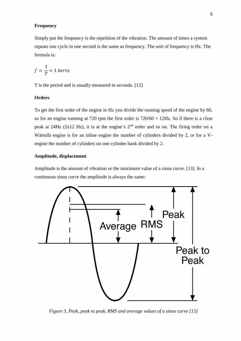
Amplitude, displacement
Amplitude is the amount of vibration or the maximum value of a sinus curve. [13]. In a
continuous sinus curve the amplitude is always the same:
Figure 3. Peak, peak to peak, RMS and average values of a sinus curve [15]
7
Peak
Peak is the maximum value of a vibration in a given interval, usually the maximum
deviation from the mean value in that vibration. [14]. In a vibration spectrum the peak
value is always the highest value.
RMS
Vibration amplitude values are given as RMS values in the spectrum. RMS is relevant
because it takes into account both the time history of the wave and gives an amplitude
value, which is important because the amplitude gives the energy of the vibration and that
is how destructive the vibration is. The formula for RMS is:
𝑇𝑜𝑡𝑎𝑙 𝑅𝑀𝑆 = √∑ 𝑥𝑖2
𝑛
𝑖=1
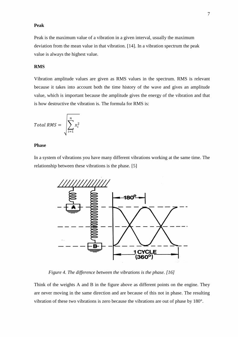
Phase
In a system of vibrations you have many different vibrations working at the same time. The
relationship between these vibrations is the phase. [5]
Figure 4. The difference between the vibrations is the phase. [16]
Think of the weights A and B in the figure above as different points on the engine. They
are never moving in the same direction and are because of this not in phase. The resulting
vibration of these two vibrations is zero because the vibrations are out of phase by 180°.

8
Damping
The damper in the system is affected by an applied force that is proportional to the relative
velocity of the connection points of the damper, giving us:
𝑭 = 𝒄(𝒙 −̇ 𝒖)̇
where c is the damping coefficient and �̇� and �̇� are the velocity of the fastening points of
the damper. The damper is ideal and is considered to have no mass so the force is equal but
opposite at each end. [3]
Natural frequency
The natural frequency of a system is the frequency at which it will continue to vibrate if
exited. For example, the frequency of the A string on a guitar is tuned to 440Hz, becoming
its natural frequency, and will continue to vibrate at that frequency for a long time after the
string has been picked.
The natural frequency of a system is determined by a series of expressions. In an
undamped system we get the expression:
𝑚�̈� + 𝑘𝑥 = 0
X=0 equalizes the equilibrium position of the system’s mass. When breaking out x from
the previous formula we get:
𝑥 = 𝐴 sin √𝑘
𝑚 𝑡 + 𝐵 cos √
𝑘
𝑚 𝑡
The term√𝑘
𝑚 is the angular natural frequency of the system which is defined by:
𝜔 = √𝑘
𝑚 which is in radians/second.
The time it takes to complete one cycle is called the period:
𝜏 =2𝜋
𝜔𝑛
When combining these definitions you get the expression for the natural frequency, fn
𝑓𝑛 =1
𝜏=
𝜔𝑛
2𝜋=
1
2𝜋√
𝑘
𝑚

9
Rigid body
A flexibly mounted structure has six ways of moving. There are three translational modes:
movement along the longitudinal, transversal and vertical axes. There are also three
rotational modes: pitching, yawing and rolling around the axes. In these six modes there is
no deformation and the structure moves as a rigid body. [5][10]. For each order of the
natural frequency of the structure there is a specific movement. When a body is flexibly
mounted you can isolate it from the vibrations with springs or rubber mounts.
𝒇𝒏 =𝟏
𝟐𝝅√
𝒌
𝒎
The operation mode shape or the operational deflection shape is the combined movement
of these six modes for all their frequencies and all orders when the engine is running.
Basically it is the way the engine is moving at running speed. [Discussion with Mr. Claus
Paro and Mr. Manjunath Patil]
Elastic body
An elastic body has many ways of moving but the three simplest ways of moving are 1st
bending, 1st torsion and 1st order vertical bending. Each peak in the spectrum represents a
different way of moving, so an elastic body has infinitive body modes. [5][10]
Figure 5. The different bending modes of a steel plate, 1st Order [20]

10
Forced vibration
Forced vibrations are the movements that are the result of a continuously applied force that
causes the system to vibrate. This force can be a strict force on the system, or the
movement of the system foundation. If the mass of an undamped single degree of freedom
system is exited by a force, the results are either the amplitude of the motion of the mass
called motion response or the applied force that is transmitted through the system to the
foundation of the system called force transmissibility.
If it is the foundation that is moving, the resulting motion is usually a result of the
amplitude of the motion of the mass compared to the amplitude of the motion of the
foundation. This is called the system’s motion transmissibility. [4]
Resonance
If an excitation is the same as or close to a natural frequency, the amplitudes will grow and
amplify each other, or resonate, creating a dangerous situation since high amplitudes can
damage the structure. How much the amplitudes grow is dependent on the damping of the
system, the higher the damping the less the amplification. When a structure resonates it is
vibrating in its natural frequency or in a frequency very close to it. [8]. The tone you hear
when you hit a metal object is the dominant resonance frequency of that structure.
Figure 6. The resonance frequency can be clearly seen as a high peak in the spectrum. [5]
11
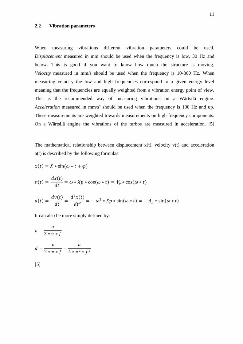
2.2 Vibration parameters
When measuring vibrations different vibration parameters could be used.
Displacement measured in mm should be used when the frequency is low, 30 Hz and
below. This is good if you want to know how much the structure is moving.
Velocity measured in mm/s should be used when the frequency is 10-300 Hz. When
measuring velocity the low and high frequencies correspond to a given energy level
meaning that the frequencies are equally weighted from a vibration energy point of view.
This is the recommended way of measuring vibrations on a Wärtsilä engine.
Acceleration measured in mm/s² should be used when the frequency is 100 Hz and up.
These measurements are weighted towards measurements on high frequency components.
On a Wärtsilä engine the vibrations of the turbos are measured in acceleration. [5]
The mathematical relationship between displacement x(t), velocity v(t) and acceleration
a(t) is described by the following formulas:
𝑥(𝑡) = 𝑋 ∗ sin(𝜔 ∗ 𝑡 + 𝜑)
𝑣(𝑡) = 𝑑𝑥(𝑡)
𝑑𝑡= 𝜔 ∗ 𝑋𝑝 ∗ cos(𝜔 ∗ 𝑡) = 𝑉𝑝 ∗ cos(𝜔 ∗ 𝑡)
𝑎(𝑡) = 𝑑𝑣(𝑡)
𝑑𝑡=
𝑑2𝑥(𝑡)
𝑑𝑡2= −𝜔2 ∗ 𝑋𝑝 ∗ sin(𝜔 ∗ 𝑡) = −𝐴𝑝 ∗ sin(𝜔 ∗ 𝑡)
It can also be more simply defined by:
𝑣 =𝑎
2 ∗ 𝜋 ∗ 𝑓
𝑑 =𝑣
2 ∗ 𝜋 ∗ 𝑓=
𝑎
4 ∗ 𝜋2 ∗ 𝑓2
[5]
12
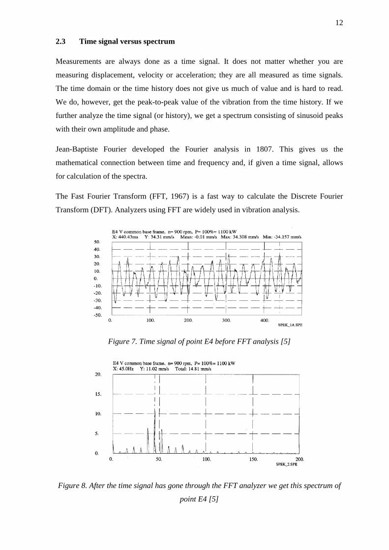
2.3 Time signal versus spectrum
Measurements are always done as a time signal. It does not matter whether you are
measuring displacement, velocity or acceleration; they are all measured as time signals.
The time domain or the time history does not give us much of value and is hard to read.
We do, however, get the peak-to-peak value of the vibration from the time history. If we
further analyze the time signal (or history), we get a spectrum consisting of sinusoid peaks
with their own amplitude and phase.
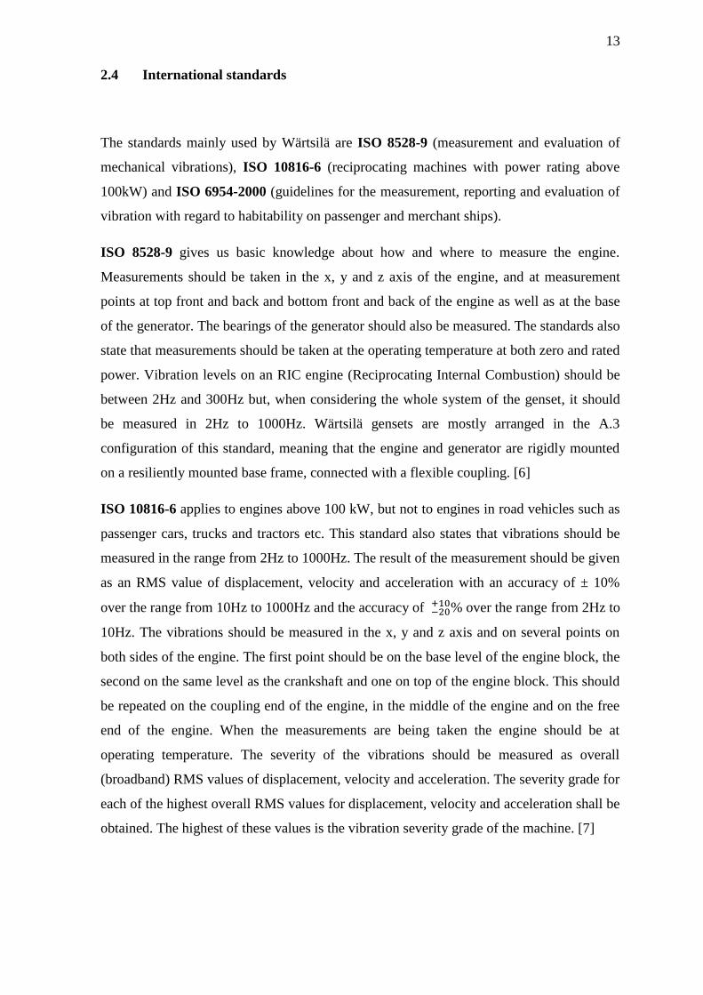
Jean-Baptiste Fourier developed the Fourier analysis in 1807. This gives us the
mathematical connection between time and frequency and, if given a time signal, allows
for calculation of the spectra.
The Fast Fourier Transform (FFT, 1967) is a fast way to calculate the Discrete Fourier
Transform (DFT). Analyzers using FFT are widely used in vibration analysis.
Figure 7. Time signal of point E4 before FFT analysis [5]
Figure 8. After the time signal has gone through the FFT analyzer we get this spectrum of
point E4 [5]
13
2.4 International standards
The standards mainly used by Wärtsilä are ISO 8528-9 (measurement and evaluation of
mechanical vibrations), ISO 10816-6 (reciprocating machines with power rating above
100kW) and ISO 6954-2000 (guidelines for the measurement, reporting and evaluation of
vibration with regard to habitability on passenger and merchant ships).
ISO 8528-9 gives us basic knowledge about how and where to measure the engine.
Measurements should be taken in the x, y and z axis of the engine, and at measurement
points at top front and back and bottom front and back of the engine as well as at the base
of the generator. The bearings of the generator should also be measured. The standards also
state that measurements should be taken at the operating temperature at both zero and rated
power. Vibration levels on an RIC engine (Reciprocating Internal Combustion) should be
between 2Hz and 300Hz but, when considering the whole system of the genset, it should
be measured in 2Hz to 1000Hz. Wärtsilä gensets are mostly arranged in the A.3
configuration of this standard, meaning that the engine and generator are rigidly mounted
on a resiliently mounted base frame, connected with a flexible coupling. [6]
ISO 10816-6 applies to engines above 100 kW, but not to engines in road vehicles such as
passenger cars, trucks and tractors etc. This standard also states that vibrations should be
measured in the range from 2Hz to 1000Hz. The result of the measurement should be given
as an RMS value of displacement, velocity and acceleration with an accuracy of ± 10%
over the range from 10Hz to 1000Hz and the accuracy of −20+10% over the range from 2Hz to
10Hz. The vibrations should be measured in the x, y and z axis and on several points on
both sides of the engine. The first point should be on the base level of the engine block, the
second on the same level as the crankshaft and one on top of the engine block. This should
be repeated on the coupling end of the engine, in the middle of the engine and on the free
end of the engine. When the measurements are being taken the engine should be at
operating temperature. The severity of the vibrations should be measured as overall
(broadband) RMS values of displacement, velocity and acceleration. The severity grade for
each of the highest overall RMS values for displacement, velocity and acceleration shall be
obtained. The highest of these values is the vibration severity grade of the machine. [7]
14
ISO 6954-2000 deals with the effects of vibrations on ships on humans. Measurements
shall be done in enough places so you get an idea of the vibration levels in the whole ship.
Measurements are required in all three directions and on at least two places on each deck
with a frequency range from 1Hz to 80Hz. Each measurement must last at least one
minute, two minutes if there are significant frequencies below 2Hz. The results must be
given in RMS values. [9]

15
3 Measurements
The measurements are performed on different points on the engine. The engine block, the
generator and the common base frame have specific measurement points. The auxiliary
equipment on the engine, pumps, filters etc. are also measured. When measuring the
engine the crankshaft of the engine shall always be in the longitudinal direction, but when
measuring on the turbocharger the TC shaft shall be used as the longitudinal direction.
Figure 9. Longitudinal, transverse and vertical directions
on the engine and the turbocharger [5]
Figure 10. Measurement points on a W32/34 V-engine. [22]

16
3.1 Accelerometer
Accelerometers are used to pick up the vibrations from the object that is being measured.
They can be simple hand-held accelerometers that only measure in one direction or more
complicated accelerometers measuring in all three directions.
Depending on the frequency there are a couple of different ways to mount the
accelerometers onto the object of measurement. The accelerometers can be stud mounted,
which can handle vibrations of up to 50 kHz. [17]. They can be glued to the object and can
then be used for vibrations of up to 2-5 kHz depending on the glue frequency [5]. Wärtsilä
usually uses magnetically mounted accelerometers when performing measurements. If the
surface that is being measured isn’t magnetic, a small piece of metal is glued to the surface
so that the magnet can stick on. Magnetically mounted accelerometers can be accurately
used up to 2-3 kHz. [5]. The last way of mounting the accelerometer is by hand. This isn’t
very accurate and one can only measure frequencies of up to 1 kHz. [5]
Accelerometers used by Wärtsilä. The two in the front row measure vibrations in all three
directions, the ones in the back row only measure one direction. The one at the back to the
right needs an amplifier. All accelerometers in the picture are mounted onto magnets.

17
3.2 Analyzer
Wärtsilä uses the OROS 34 multichannel FFT analyzer and a Benstone portable analyzer.
These are used to analyze the time signal from the measurements. The Oros 34 must be
connected to a computer while the Benstone can be used as it is. The Oros has eight
channels and an output channel while the Benstone has four channels. Both are used to
record data that later can be analyzed, but with the Oros you can analyze in real time on the
computer while the measurements are being done. The Benstone is more like a recorder.
You can see an FFT spectrum on the screen but you cannot modify anything. The Benstone
is good for doing simple and quick vibration measurements because it’s hand-held.
Figure 11. Oros 34 Multichannel FFT analyzer [18]
Figure 12. Benstone Impaq portable FFT analyzer [19]

18
3.3 Spectrum
The spectrum is the analyzed time signal in frequency level after the FFT analysis. The
spectrum shows the amplitudes and frequencies of the vibrations. The values are shown
either as RMS values or Peak values. In the spectrum you can see where you have the
highest amplitudes and at what frequency. Every peak in the spectrum is an excitation from
the engine. If one frequency is very dominant it normally means the structure is resonating
at this frequency. If you have high vibration levels on an engine it is very important to
know the frequencies. The frequencies will give information about the engines and help
you understand how the structure is moving, and then you can solve the problem. [25]
Figure 13. Spectrum at 100% load at measuring point A4a on the engine.
19
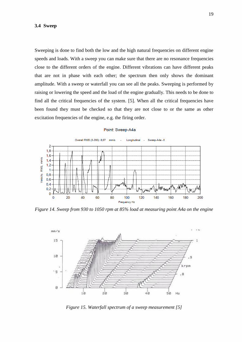
3.4 Sweep
Sweeping is done to find both the low and the high natural frequencies on different engine
speeds and loads. With a sweep you can make sure that there are no resonance frequencies
close to the different orders of the engine. Different vibrations can have different peaks
that are not in phase with each other; the spectrum then only shows the dominant
amplitude. With a sweep or waterfall you can see all the peaks. Sweeping is performed by
raising or lowering the speed and the load of the engine gradually. This needs to be done to
find all the critical frequencies of the system. [5]. When all the critical frequencies have
been found they must be checked so that they are not close to or the same as other
excitation frequencies of the engine, e.g. the firing order.
Figure 14. Sweep from 930 to 1050 rpm at 85% load at measuring point A4a on the engine
Figure 15. Waterfall spectrum of a sweep measurement [5]

20
3.5 Operation deflection shape
Operation Deflection Shape (ODS) is the way a structure is moving during operation, or
how different parts of the structure are moving compared to each other. With ODS you can
find out if the structure is moving as a rigid body or if it’s moving as an elastic body. When
you know how the structure is moving in the actual frequency range, it is much easier to
find a remedy for any problem. The measurements from the different points on the engine
can then be made into a simple model of how the engine is moving during operation. [5]
3.6 Modal
The modal measurement is performed to find the natural frequencies and mode shapes of
the engine. The modal measurement is performed by placing a sensor on the object being
measured and hitting the object with a hammer also connected to a sensor. This gives you
an impact force from the hammer and a response on the structure. It’s a quick way to find
the natural frequency of a structure. [21]

21
3.7 Shaker
The purpose of a shaker measurement is to find the natural frequency of a component or
even the whole engine. If it is a small component it can be placed on a shaker table. When
performing a shaker test on a whole engine a hydraulic cylinder is attached to the engine
and is made to vibrate randomly. This is very similar to the modal test but will give you a
better result.
Figure 16. Component on a shaker table. [5]
Figure 17. Shaker test of a complete Genset, using a hydraulic shaker [5]

22
4 Wärtsilä vibration guidelines
In this chapter I will go through the acceptable vibration levels on different mechanical and
electrical parts of the engine. These levels originate in the many years of experience of
their engines found at Wärtsilä, but also in the acceptable levels stated in the ISO
standards. The chapter also includes a short summary of previous research in the subject.
4.1 Earlier research
You can say that Wärtsilä has been researching vibrations ever since the sixties when they
started measuring vibrations on the engines. In the eighties Wärtsilä started analyzing the
vibrations.
In 2009, Mr. Mohd Afzal wrote his Master of Science thesis in sound and vibration at
Kungliga Tekniska Högskolan, KTH in Stockholm, Sweden. The thesis entitled “Flexible
Mounting System Design, Theory and Practice” was done on behalf of Wärtsilä. The focus
of his thesis was on finding suitable vibration isolators and a good way to isolate the
electronic box from the engine excitations. The electrical box contains critical control
systems needed when running the engine.
4.2 Wärtsilä standard/acceptable vibration levels
The maximum allowed vibration level on a Wärtsilä engine complies with ISO 10816-6.
According to the ISO 10816-6 vibration severity grade 18, the overall vibrations of the
engine should be kept under the values mentioned in severity grade 18. Severity grade 18
states that overall vibrations should be kept under 283 μm (RMS) displacement, 17.8 mm/s
(RMS) velocity and 27.9 m/s² (RMS) acceleration. These severity grades must be used in
the frequency range of 2Hz to 1000 Hz. [Email Discussion 30.1.2014]
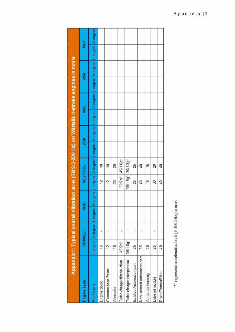
The typical overall vibration level on the engine block of a W20 engine is 15 mm/s, on a
W32/34SG L-engine it is 12 mm/s and on a W32/34SG V-engine 10 mm/s (RMS: 3-
200Hz).
23
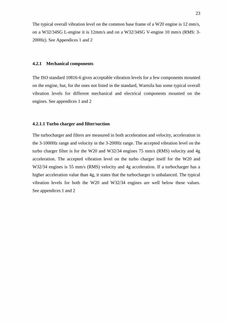
The typical overall vibration level on the common base frame of a W20 engine is 12 mm/s,
on a W32/34SG L-engine it is 12mm/s and on a W32/34SG V-engine 10 mm/s (RMS: 3-
200Hz). See Appendices 1 and 2
4.2.1 Mechanical components
The ISO standard 10816-6 gives acceptable vibration levels for a few components mounted
on the engine, but, for the ones not listed in the standard, Wartsila has some typical overall
vibration levels for different mechanical and electrical components mounted on the
engines. See appendices 1 and 2
4.2.1.1 Turbo charger and filter/suction
The turbocharger and filters are measured in both acceleration and velocity, acceleration in
the 3-1000Hz range and velocity in the 3-200Hz range. The accepted vibration level on the
turbo charger filter is for the W20 and W32/34 engines 75 mm/s (RMS) velocity and 4g
acceleration. The accepted vibration level on the turbo charger itself for the W20 and
W32/34 engines is 55 mm/s (RMS) velocity and 4g acceleration. If a turbocharger has a
higher acceleration value than 4g, it states that the turbocharger is unbalanced. The typical
vibration levels for both the W20 and W32/34 engines are well below these values.
See appendices 1 and 2
24
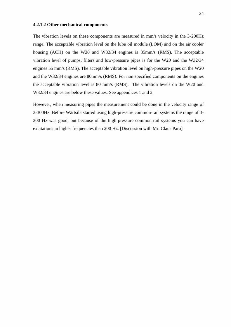
4.2.1.2 Other mechanical components
The vibration levels on these components are measured in mm/s velocity in the 3-200Hz
range. The acceptable vibration level on the lube oil module (LOM) and on the air cooler
housing (ACH) on the W20 and W32/34 engines is 35mm/s (RMS). The acceptable
vibration level of pumps, filters and low-pressure pipes is for the W20 and the W32/34
engines 55 mm/s (RMS). The acceptable vibration level on high-pressure pipes on the W20
and the W32/34 engines are 80mm/s (RMS). For non specified components on the engines
the acceptable vibration level is 80 mm/s (RMS). The vibration levels on the W20 and
W32/34 engines are below these values. See appendices 1 and 2
However, when measuring pipes the measurement could be done in the velocity range of
3-300Hz. Before Wärtsilä started using high-pressure common-rail systems the range of 3-
200 Hz was good, but because of the high-pressure common-rail systems you can have
excitations in higher frequencies than 200 Hz. [Discussion with Mr. Claus Paro]
25
4.2.2 Electrical components
The different electrical parts mounted on the engine are of course vibrating with the engine
at different amplitudes and frequencies. Wärtsilä has many years of experience of
vibrations on their engines and has set some vibration levels adjoining with ISO 10816-6
that used to be considered acceptable vibration levels. The displacement level in the 2-10
Hz range is for an Isolated Electrical Component (IEC) 0.5mm (RMS), and for a non-IEC
1.1mm (RMS). The upper velocity allowed in the frequency range of up to 200 Hz is
30mm/s (RMS) for an IEC and for a non-IEC 80mm/s (RMS). The highest acceleration
value for an IEC in the 200Hz to 1 kHz range is 3g (RMS) and for a non-IEC 10g (RMS).
However, any single frequency component exceeding 75% of the RMS value isn’t allowed.
The maximum limit for a single acceleration component is 2.5g in the range from 0.2 to
0.5 kHz, and 5g in the range from 0.5 to 1 kHz and 10g in the range from 1 kHz to 2 kHz.
See appendix 2.
However, these levels may need to be reconsidered as Mr. Afzal states in a report written
after a shaker test on a pressure sensor performed at Technobotnia on 25-26 February
2013.
Typical vibration levels for an IEC on the W20, V and L W32/34SG is 25 mm/s (RMS),
for a non-IEC on the W20 35mm/s (RMS) and on the V and L W32/34SG 40 mm/s
(RMS). See appendix 1.
26
4.3 Natural frequencies of different components
The natural frequencies of different components can be mathematically found with a FEM
analysis, or with a shaker test or a modal, hammer, test. The natural frequency of a single
component is needed to make sure it is not close to one of the orders of the engine. When
you know the natural frequency of a component you can more easily choose the correct
damper for the component. As a rule of thumb the natural frequencies of the different parts
must be above the firing order of the worst engines or above 75Hz; in most cases this will
be on the safe side.
For example the order for the firing frequency of a W20V32 is the number of cylinders on
one bank divided by 2, or 5 in this case. So depending on if the engine is running at
720rpm, 12Hz, or 750 rpm, 12.5Hz, the natural frequency of the component must be above
5*12Hz = 60 Hz or 5*12.5Hz = 62.5 Hz. But 75Hz is the number to use. [Discussion with
Mr. Kari Saine]

27
4.4 Test components/shaker table test
When performing a shaker test Wärtsilä has a few demands that need to be fulfilled. The
shaker test must consist of two tests. The first one should consist of a sine sweep from
10Hz to 140 Hz, 10 minutes per sweep for a total of six hours. This must be done in all
three directions. At different frequencies different velocities and accelerations must be
used.
Table 1. Test levels of velocity and acceleration at different frequencies
Frequency, Hz Velocity, mm/s (rms) Acceleration, m/s² (peak)
10 20 0,18
40 40 1,3
100 40 3,54
140 10 1,24
Figure 18. Test curve of the values given in table 1.
0
0,5
1
1,5
2
2,5
3
3,5
4
0
5
10
15
20
25
30
35
40
45
0 10 20 30 40 50 60 70 80 90 100 110 120 130 140 150
Acc
ele
rati
on
pe
ak (
g)
RM
S V
elo
city
(m
m/s
)
Frequencies (Hz)
Wärtsilä vibration shaker tests demand
V (rms)
28
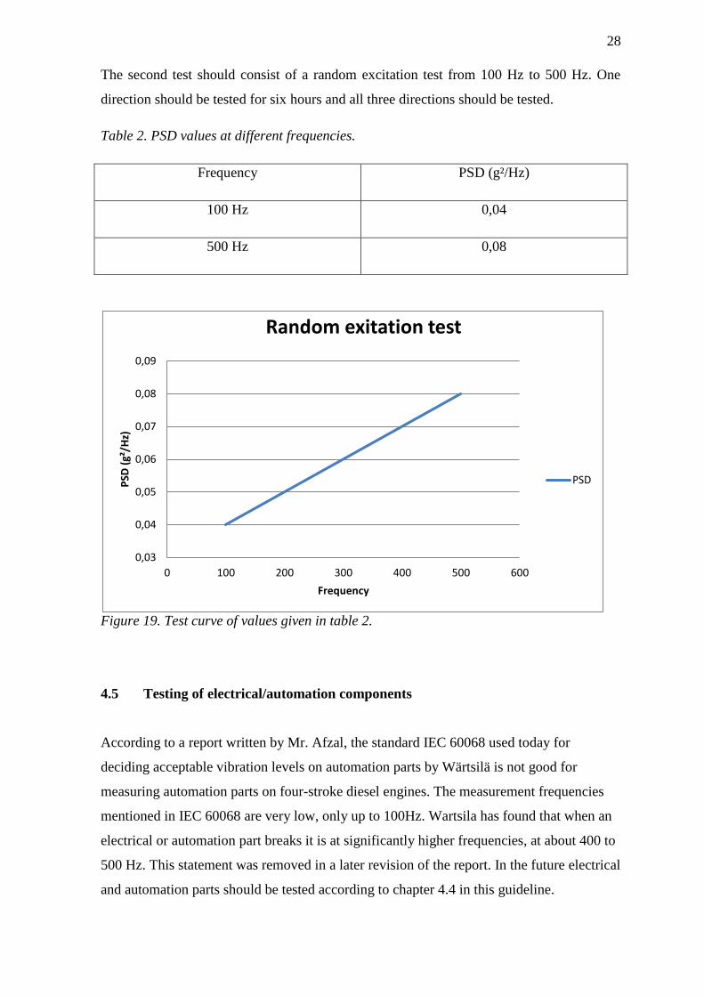
The second test should consist of a random excitation test from 100 Hz to 500 Hz. One
direction should be tested for six hours and all three directions should be tested.
Table 2. PSD values at different frequencies.
Frequency PSD (g²/Hz)
100 Hz 0,04
500 Hz 0,08
Figure 19. Test curve of values given in table 2.
4.5 Testing of electrical/automation components
According to a report written by Mr. Afzal, the standard IEC 60068 used today for
deciding acceptable vibration levels on automation parts by Wärtsilä is not good for
measuring automation parts on four-stroke diesel engines. The measurement frequencies
mentioned in IEC 60068 are very low, only up to 100Hz. Wartsila has found that when an
electrical or automation part breaks it is at significantly higher frequencies, at about 400 to
500 Hz. This statement was removed in a later revision of the report. In the future electrical
and automation parts should be tested according to chapter 4.4 in this guideline.
0,03
0,04
0,05
0,06
0,07
0,08
0,09
0 100 200 300 400 500 600
PSD
(g²
/Hz)
Frequency
Random exitation test
PSD
29
5 Method
This chapter describes the realization of the project and my working process writing the
thesis.
In September 2013, I was given the task of writing a simple guideline for measuring
vibrations on Wärtsilä engines. I was also to give clear vibration limits on the engines.
5.1 The Excel sheets
I started by filling in two Excel sheets, one with the Wärtsilä W20 engines and one with
the Wärtsilä W32/34 engines. Wärtsilä has conducted a lot of measurements on their
engines so there are a lot of vibration data available. To fill out the excel sheet I took a
measurement report, typed in the engine name, the serial number, the power rating and
how it was mounted. For each measurement point on the engine there are three vibration
values, longitudinal, transverse and vertical vibrations. These were filled into the Excel
sheet for every measured point on the engine. When there are enough measurement data
for a point on an engine, Excel calculates the mean value and the standard deviation.
These values will be used as a reference to what can be considered normal vibration levels
for each point on each type of engine.
5.2 The theory
When I started writing I began with the theory. After discussions with my supervisor at
Wärtsilä, Mr. Kari Saine, I got an idea as to which vibration theory needed to be included
in the thesis. The theory needed to contain the absolutely basic vibration theory like
amplitude, frequency and phase, but also some more advanced theory about measurements
and the analysis of the results. I had found some of the theory from the internet, from the
manufacturers of the measuring devices but mostly from the book “Harris shock and
vibration handbook, fifth edition” by Cyril M. Harris and Alan G. Piersol. The guidelines
must also follow the ISO standards to some extent. Wärtsilä mainly uses ISO-10816-6,
ISO-6954 and ISO-8528-9. However, some of the levels in the ISO standards could not be
directly applied on the Wärtsilä Vibration Guidelines.
30
5.3 ISO standards
On the engine itself Wärtsilä uses the vibration severity grade 18 from ISO 10816-6 as an
acceptable vibration level, but since ISO 10816-6 mostly covers vibrations on the engine
block only, all mechanical and electrical components mounted on the engine need to have
an acceptable vibration level of their own. Wärtsilä has made a table of which components
on the engines belong to which vibration severity grade adjoining ISO-10816-6, e.g. the
turbocharger has an acceptable vibration severity grade of 71 while the common base
frame uses grade 18. The standards fulfill most of Wärtsilä’s demands but not all of them,
so in some areas Wärtsilä needs to come up with their own standards. Electrical
components used to be classified under grades 28 and 71 depending on if they were
isolated from vibrations or not, but Mr. Afzal came to the conclusion that Wärtsilä needs to
come up with their own vibration levels for the electrical components. This is the only case
that differs from the ISO standards.
6 Results
The result of this thesis is basically the thesis itself as it will be used as the guideline. I
have collected the number of guides that were already available at Wärtsilä into one
document, which was the purpose of the thesis from the beginning. In this thesis I have
gathered basic vibration theory to get a basis for the guideline and some more advanced
theory needed when analyzing a vibration measurement. The equipment used by Wärtsilä
when performing vibration measurements is also presented in the thesis. The acceptable
vibration levels needed to have a base in the standards given by the different classification
societies. The standards mainly used by Wärtsilä for their engines are ISO 8528-9, ISO
10816-6 and ISO 6954-2000 and I found that they work well with the demands made by
Wärtsilä. However, it was found out that when testing automation components for the
engines, the testing standard IEC 60068 was not good enough for Wärtsilä’s demands so
Wärtsilä will write their own standards for testing automation components. The acceptable
vibration levels for a Wärtsilä engine adjoining ISO 10816-6 can be found in appendix 2
and the typical vibration levels on Wärtsilä engines based on years of vibration
measurements can be found in appendix 1.
31
7 Conclusions
The goal of this thesis was to write an updated guideline where Wärtsilä’s knowledge of
vibrations was to be collected in one document. The typical vibration levels on the engines
have been gathered as well as the critical levels. The vibration levels in ISO 10816-6 are
still acceptable for the mechanical components on the engine. We have found that the old
way of performing shaker tests according, to standard IEC 60068, on electrical and
automation components is not good enough for Wärtsilä’s use and Wärtsilä has come up
with a new way of testing these components. See chapter 4.4. This will lead to new
demands being made on subcontractors. In some cases when measuring pipes it is
necessary to increase the range of the spectra from 3-200Hz to 3-300Hz. This is needed
because of the relatively new common-rail fuel-injection systems that can have excitations
in higher frequencies. It has also become clear that today’s international standards do not
fulfill all of Wärtsilä’s demands. Because of this Wärtsilä will have to make their own
standard for acceptable vibration levels on their 4-stroke diesel and gas engines. Hopefully
this guideline will come to good use in Wärtsilä in the future.

32
8 List of sources
[1] Introduction to mechanical vibrations (n.d).
http://www.newagepublishers.com/samplechapter/001413.pdf
Accessed 8.11.2013
[2] Harris, C & Piersol, A. (2002). Harris’ shock and vibration handbook, fifth edition.
New York: McGraw-Hill
Page 2.1
[3] Harris, C & Piersol, A. (2002). Harris’ shock and vibration handbook, fifth edition.
New York: McGraw-Hill
Page 2.2
[4] Harris, C & Piersol, A. (2002). Harris’ shock and vibration handbook, fifth edition.
New York: McGraw-Hill
Page 2.7
[5] Wärtsilä Vibration basic course (17.01.2011)
Internal Wärtsilä document
[6] ISO 8528-9
Vibration standard, measurement and evaluation of mechanical vibrations.
[7] ISO 10816-6
Vibration standard, reciprocating machines with power rating above 100kW.
[8] Introduction to excitation forces of a four-stroke diesel engine. (n.d)
Internal Wärtsilä document.
[9] ISO 6954-2000
Vibration standard, guidelines for the measurement, reporting and evaluation of vibration
with regard to habitability on passenger and merchant ships.
[10] Malcolm, C. (2007). Handbook of noise and vibration control.
New Jersey: John Wiley & sons, Inc.
Chapter 3.4.2, Page 235
[11] Basic vibration system
http://s3.amazonaws.com/answer-board-image/7e3b7493-a945-4aba-9c34-
358b08a0a7ad.jpeg
Accessed 21.2.2014
[12] Malcolm, C. (2007). Handbook of noise and vibration control.
New Jersey: John Wiley & sons, Inc.
Chapter 3.1, page 2

33
[13] Harris, C & Piersol, A. (2002). Harris’ shock and vibration handbook, fifth edition.
New York: McGraw-Hill
Page 1.16
[14] Harris, C & Piersol, A. (2002). Harris’ shock and vibration handbook, fifth edition.
New York: McGraw-Hill
Page 1.23
[15] Peak to Peak
https://assets.newport.com/web600w-EN/images/1245675.gif
Accessed 7.3.2014
[16] Phase
http://freevibrationanalysis.blogspot.fi/2011/08/brief-introduction-to-vibration_04.html
Accessed 21.2.2014
[17] Harris, C & Piersol, A. (2002). Harris’ shock and vibration handbook, fifth edition.
New York: McGraw-Hill
Page 15.9
[18] Oros 34
http://www.oros.com/uploads/Image/2c/WEB_CHEMIN_13643_1319031608.jpg
Accessed 17.2.2014
[19] Benstone portable analyzer
http://www.benstone.com/products_pn_impaq.html
Accessed 17.2.2014
[20] Plate modes
http://www.thorlabs.com/tutorials/Table24.gif
Accessed 26.2.2014
[21] Harris, C & Piersol, A. (2002). Harris’ shock and vibration handbook, fifth edition.
New York: McGraw-Hill
Page 21.35
[22] W32-34_V engine measurement point
Internal Wärtsilä document
A p p e n d i x | 1

A p p e n d i x | 2
Co
mp
on
en
t n
am
eD
isp
lac
em
en
t [2
-10
Hz
]
mm
(r.
m.s
)
Ve
loc
ity
[1
0-2
00
Hz
]
mm
/s (
r.m
.s)
Ac
ce
lera
tio
n [
20
0-1
00
0 H
z]
m/s
² (r
.m.s
)
Vib
rati
on
se
ve
rity
gra
de
IS
O 1
08
16
-6
Co
mm
on b
ase
fra
me
(C
BF
), B
ea
ring
0,3
20
2g
18
Eng
ine
blo
ck, A
ltern
ato
r &
IEC
0,5
30
3g
28
LO
M a
nd
AC
H
0,6
35
3g
45
TC
C,p
um
ps, F
ilte
r &
Lo
w p
ressure
pip
e0
,95
54
g7
1
Turb
o c
ha
rge
r filte
r1
,27
54
g7
1
Hig
h p
ressure
pip
e, A
uto
ma
tio
n p
art
& N
on-IE
C1
,18
01
0g
71
No
n-s
pe
cifie
d c
om
po
ne
nts
1,1
70
8g
71
No
te: a
) A
ny
sin
gle
fre
que
ncy
co
mp
one
nt e
xce
ed
ing
75
% o
f th
e r
.m.s
lim
it isn't
acce
pta
ble
.
b
) M
ax
limit fo
r sin
gle
fre
que
ncy
acce
lera
tio
n c
om
po
ne
nt is
2.5
g in the
fre
que
ncy
rang
e o
f 0
.2-0
.5 K
Hz,
5g
in the
fre
que
ncy
rang
e o
f 0
.5-1
KH
z
Ap
pe
nd
ix2
W
ärt
silä
sta
nd
ard
fo
r a
cc
ep
tab
le v
ibra
tio
n le
ve
ls o
n 4
-str
ok
e e
ng
ine
s-
ad
join
ing
IS
O 1
08
16
-6
Ab
bre
via
tio
n: L
OM
=L
ub
e o
il m
od
ule
, A
CH
=A
ir c
oo
ler
ho
usin
g, T
C=
Turb
o c
ha
rge
r co
mp
resso
r, IE
C=
Iso
late
d e
lectr
ica
l co
mp
one
nt