Vibration and Thermal Vacuum Qualifi¢.,.tior Test … a Low-Voltage Tungsten-Halogen Light Lewis...
12
NASA Contractor Report 187050 Vibration and Thermal Vacuum Qualifi¢.,.tior_ Test Results for a Low-Voltage Tungsten-Halogen Light (_ACA-C;_-! _Tu_o) VTO_>ATIql_ ANIJ Tk4L_-_L Ngi-lP3?b V_cti_j:!,, :UALIr IC),[T_: _ ..I 3ULT3 Fq_ A L_]W-V!-_LTA_,c IUNr..._,TL_-!'I,_L_!.;L _'f I.[I:;H r t:in:_l :.,,,r. or" (_'v<_r+#ru_ l"_Chriolo'._Y) Ii i_ C_CL 137 > uncl :_s G,_I31 0001717 J. Andrew Sexton Sverdrup Technology, Inc. Lewis Research Center Group Brook Park, Ohio February 1991 Prepared for Lewis Research Center Under Contract NAS3-25266 National Aeronautics and Space Administration https://ntrs.nasa.gov/search.jsp?R=19910010012 2019-05-11T19:55:41+00:00Z
Transcript of Vibration and Thermal Vacuum Qualifi¢.,.tior Test … a Low-Voltage Tungsten-Halogen Light Lewis...

NASA Contractor Report 187050
Vibration and Thermal Vacuum Qualifi¢.,.tior_
Test Results for a Low-Voltage
Tungsten-Halogen Light
(_ACA-C;_-! _Tu_o) VTO_>ATIql_ ANIJ Tk4L_-_L Ngi-lP3?b
V_cti_j:!,, :UALIr IC),[T_: _ ..I 3ULT3 Fq_ A
L_]W-V!-_LTA_,c IUNr..._,TL_-!'I,_L_!.;L _'f I.[I:;H r t:in:_l
:.,,,r.or" (_'v<_r+#ru_ l"_Chriolo'._Y) Ii i_ C_CL 137 > uncl :_sG,_I31 0001717
J. Andrew Sexton
Sverdrup Technology, Inc.
Lewis Research Center Group
Brook Park, Ohio
February 1991
Prepared for
Lewis Research Center
Under Contract NAS3-25266
National Aeronautics and
Space Administration
https://ntrs.nasa.gov/search.jsp?R=19910010012 2019-05-11T19:55:41+00:00Z

Trade names or manufacturers' names are used in this report for identification
only. This usage does not constitute an official endorsement, either expressed or
implied, by the National Aeronautics and Space Administration.
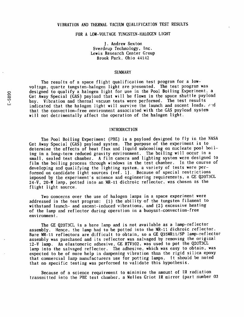
VIBRATION AND THERMAL VACUUM QUALIFICATION TEST RESULTS
FOR A LOft-VOLTAGE TUNGSTEN-HALOGEN LIGHT
J. Andrew SextonSverdrup Technology, Inc.
Lewis Research Center GroupBrook Park, Ohio 44142
C
O0I-0
!
SUMMARY
The results of a space flight qualification test program for a low-voltage, quartz tungsten-halogen light are presented. The test program wasdesigned to qualify a halogen light for use in the Pool Boiling Experiment. aGet Away Special (GAS) payload that will be flown in the space shuttle payloadbay. Vibration and thermal vacuum tests were performed. The test resultsindicated that the halogen light will survive the launch and ascent loads, _-_dthat the convection-free environment associated with the GAS payload system
will not detrimentally affect the operation of the halogen light.
INTRODUCTION
The Pool Boiling Experiment (PBE) is a payload designed to fly in the NASAGet Away Special (GAS) payload system. The purpose of the experiment is todetermine the effects of heat flux and liquid subcooling on nucleate pool boil-
ing in a long-term reduced gravity environment. The boiling will occur in asmall, sealed test chamber. A film camera and lighting system were designed tofilm the boiling process through windows in the test chamber. In the course of
developing and qualifying the lighting system, a variety of tests were per-formed on candidate light sources (ref. 1). Because of special restrictionsimposed by the experiment's science and engineering requirements, a GE Q2OT3CL24-V, 20-ff lamp, potted into an MR-11 dichroic reflector, was chosen as the
flight light source.
Two concerns over the use of halogen lamps in a space experiment wereaddressed in the test program: (1) the ability of the tungsten filament towithstand launch- and ascent-induced vibrations, and (2) excessive heating
of the lamp and reflector during operation in a buoyant-convection-freeenvironment.
The GE Q2OT3CL is a bare lamp and is not available as a lamp-reflectorassembly. Hence, the lamp had to be potted into the MR-11 dichroic reflector.Bare MR-11 reflectors are difficult to obtain, so a GE Q35MRll/SP lamp-reflector
assembly was purchased and its reflector was salvaged by removing the original12-V lamp. An elastomeric adhesive, GE RTVI02, was used to pot the Q2OT3CLlamp into the salvaged reflector. The adhesive, which was easy to obtain, wasexpected to be of more help in dampening vibration than the rigid silica epoxythat commercial lamp manufacturers use for potting lamps. It should be notedthat no specific testing was performed to validate this hypothesis.
Because of a science requirement to minimize the amount of IR radiationtransmitted into the PBE test chamber, a Melles Griot IR mirror (part number 03

MHG007), attached in front of the lamp, was included in the light assemblydesign. The mirror reflected nearly all of the forward-directed IR radiationback toward the lamp and out the backside of the dichroic reflector. There
was some concern that the reflected IR radiation might raise the temperatureof the lamp too much during operation.
Although halogen lamps are designed to operate at relatively high tempera-tures, the lamp design and the experiment itself dictate how high the tempera-tures can be. The molybdenum strip in the lamp seal is restricted to operationat less than 662 °F (350 °C), or degradation of the seal can occur. A degradedseal could cause a loss of the high-pressure gas inside the lamp and therebylead to failure of the filament. The experiment design also imposes a uniquetemperature limit. The test chamber where the boiling activity occurs isfilled with R-113 (trichlorotrifluoroethane), a fluid that is normally quitebenign. However, if R-113 should leak from the test chamber and come into con-
tact with the two halogen lamps on the exterior of the test chamber, and ifany part of the lamps were at a temperature of 572 °F (300 °C) or higher, theR-113 could thermally decompose into fluorine, chlorine, and other products.Since these by-products are so corrosive, ensuring that the operating tempera-ture of the lamps will not reach the R-113 thermal breakdown threshold becomesvery important.
BACKGROUND
Tungsten-halogen lamps are quite similar to normal tungsten filamentlamps, except that they have a trace of halogen (normally bromine) added to thefill gas and they operate with higher internal gas pressures. The addition ofthe halogen results in a regenerative cycle of the evaporated tungsten; thisexplains why the halogen lamps are capable of operating at higher tempera-tures, and thus higher efficiencies, than standard tungsten lamps. In orderfor the halogen cycle to operate, the internal wall temperature of the lampmust be at least 482 °F (250 *C) (ref. 2). When operated at rated voltage,the lamps are designed to run at this temperature in 1-g environments.
The present PBE lighting system design requires two lights that will be
operated at different voltages, 14 and 24 V dc, at different times during theexperiment. At 14 V dc, the temperature of the quartz lamp interior wall willnot reach a temperature high enough to cause the regenerative halogen cycle tofunction. This condition is not detrimental to the filament, because the
reduced voltage decreases the filament temperature to a point where evaporationof the tungsten is negligible (ref. 2). At lower than rated voltage, theexpected lifetime of the lamp tends to increase, albeit at the expense of lumi-nous efficiency.
The concern about high lamp-operating temperatures prompted the perform-
ance of several thermal vacuum tests to verify that the steady-state operatingtemperatures would remain lower than the R-113 thermal decomposition limit of572 °F (300 °C). These tests sought to replicate the cooling conditions thatwill exist inside the GAS canister during flight operations.

PRIOR FLIGHT DATA
A GAS payload, the Halogen Lamp Experiment (HALEX), was flown on STS 41G
to gain a better understanding of the operation of halogen lamps in reducedgravity environments. The investigators, Schmitt and Stapelmann (ref. 3), con-cluded (1) that there were no detectable disturbances of the halogen cycle(i.e., no deposits of tungsten on the bulb), and (2) that the surface charac-teristics of the filament after flight were as expected. Furthermore, theyconcluded that the absence of convection (under microgravity) inside the lampreduced the convective heat transfer from 5 percent to about 2 percent; thisreduced heat transfer, in turn, increased the tungsten filament temperature by
about 68 *F (20 °C) and the light efficiency by about 8.8 percent. The lampflown in the HALEX experiment was a 45-W unit that was designed as a precursorto a 300-W lamp to be used in a materials processing experiment. The 45-W lamp
was operated for about 58 hr during space flight.
DESCRIPTION OF FLIGHT LIGHT ASSEMBLY
The design of the flight light assembly is illustrated in figure 1. Themain bracket is made from 6061-T6 aluminum. The dichroic reflector is sand-wiched between the main bracket and the front IR mirror holder. An adhesive,
silicone RTV, was used to glue the reflector to the main bracket and to gluethe IR mirror to the front mirror holder. A small amount of RTV was usedbetween the reflector and the IR mirror, but care was taken not to seal themirror to the reflector. A commercial ceramic electrical connector supplied
power to the lamp. The connector had no locking features, so it was safetywired to the main bracket.
TEST
Equipment
Thermal testing was done in a small vacuum chamber that was equipped withelectrical feed-throughs for both power and thermocouple leads. The minimumpressure obtained in the bell chamber was approximately 0.2 psia (1.4 mbar);this was deemed sufficient to decrease convective cooling to a small ordereffect.
For vibration testing, the NASA Lewis Vibration Measurement and Testfacility was utilized. A small aluminum adapter bracket was fabricated toallow the lamp assembly to be mounted in a cantilever manner similar to the
experiment flight mounting.
Procedure
Other than a few minutes of normal operation at rated voltage, the lightassembly received no special preconditioning prior to the start of qualifica-tion testing. The light assembly was first vibration-tested and then, subse-quently, used for the thermal vacuum testing.

Vibration testing. - Two phases of vibration testing were performed: inthe first phase, the lamp-reflector assembly itself was hard-mounted directlyto the vibration table; in the second phase, it was assembled into a flightlikemounting bracket and then attached to the vibration table.
Low-level-sine-sweep and random inputs were applied during both testphases. During the hard-mount sine-sweep tests, 5-, 10-, and 15-g rms inputswere applied over a range of 5 to 2000 Hz. With the flightlike mounting hard-ware, the sine-sweep test was performed at 5 g rms with an accelerometer on thebracket to record the response. A 13.4-g rms random vibration input was con-structed from data given in the Get-Away-Special experimenter handbook (ref. 4)(see fig. 2); this input was applied to both mounting configurations of thelamp-reflector assembly.
During the hard-mount tests, the lamp-reflector assembly was subjected tovibration along the two axes that corresponded to directions parallel and per-pendicular to the filament's coil. During the tests involving the lamp-reflector assembly and the flightlike mounting bracket, vibrations we;e appliedalong the three principle axes of the mounting bracket.
Thermal testing. - After the vibration tests, thermal tests were conductedin an ambient pressure environment and then in a vacuum chamber. The room-
pressure tests helped to establish a baseline from which to compare the thermalvacuum test data. The lamp-reflector assembly was left in the flightlikemounting bracket and instrumented with J-type thermocouples on the exterior ofthe lamp wall. The thermocouples were attached at two places on the exteriorwall, at one place on the backside of the dichroic reflector, and at one placeon the front side of the IR mirror. Figure 1 illustrates the placement of thethermocouples.
The thermal tests were conducted for periods lasting approximately 16 min,in order to allow the light assembly to attain a steady-state temperature.
During the thermal tests, the light assembly was clamped to an 8-oz blockof A1 6061, which in turn was placed on a block of G-11 material. This wasdone to simulate, in a conservative manner, the mounting of the light assemblyin the experiment. In reality, the flight light assembly will mount to a muchlarger thermal mass, so the test represented a more severe condition than wouldbe experienced during flight.
TEST RESULTS
Vibration Test Results
The light assembly was subjected to the vibration tests outlined earlier.No filament failure occurred, and no audible evidence of resonance was detected.
An accelerometer placed on the flightlike mounting bracket showed a structuralresonance at about 1300 Hz. The response of the light bracket is illustratedin figure 3.
4

Thermal Test Results
Ambient pressure. - The temperatures attained during ambient pressureoperation are shown in figure 4. The maximum temperature was recorded by thethermocouple on the lamp exterior sidewall; the lowest temperature was recordedby the thermocouple on the mirror.
Vacuum. - The temperatures attained during vacuum testing are shown infigure 5. The temperature distribution was about the same as that obtained forthe ambient pressure test, but the temperatures increased under the vacuum con-dition. The maximum steady-state temperature of the lamp exterior wall did notrise above 550 °F (288 °C). Note, however, that the lamp wall temperatureunder vacuum test conditions was approximately 50 to 60 °F (10 to 16 °C) higherthan that recorded during ambient pressure tests; this difference is close tothe HALEX experiment results reported by Schmitt and Stapelmann.
DISCUSSION OF TEST RESULTS
The presence of a structural resonance of the flight light bracket atabout 1300 Hz is not considered to be detrimental to the lamp. The vibration
environment inside the GAS canister during ascent, which is discussed in refer-ence 5, indicates that the bulk of the vibration input occurs at frequenciesunder 1000 Hz. Vibration testing showed that the flight lamp will withstandvibrations in the frequency range of 5 to 2000 Hz; these test results concurwith the general characteristics of lamps built with a C-6 type of coiledfilament.
The vacuum operating temperature of the bulb sidewall (the hottest sur-face) was shown to be about 22 °F (12 °C) below the decomposition temperaturelimit of the R-113 fluid. This temperature is considered to be conservative,because a relatively small thermal mass was used during the vacuum test. In
addition, during STS flight the GAS canister will have a 10 psia dry-nitrogenenvironment that will afford some degree of conductive cooling from the bulb
to the surrounding reflector.
The temperature data appear to track with data taken during the HALEX GASpayload flight. The increase in lamp temperature due to operation in a reducedgravity environment will be associated with an increase in light efficiency andluminous output.
The PBE photographic system was tested with various voltages for thelight, and the system design was shown to be tolerant of the expected changesin the lamp's luminous output due to increased lamp efficiency under micro-
gravity conditions.
CONCLUDING REMARKS
The GE Q2OT3CL lamp, potted with RTV adhesive into an MR-11 dichroicreflector, was demonstrated to be capable of withstanding environments similarto those experienced by Get-Away-Special class payloads. The tests showed thatthe flight light assembly will withstand the vibration loads typical of a Get-Away-Special payload and that the absence of convective cooling does not cause

a prohibitive increase in the bulb operating temperature when the bulb is oper-ated at its rated voltage, 24 V dc.
ACKNOWLEDGMENTS
The author wishes to thank Louis R. Ignaczak of Lewis Research Center forhis helpful comments and suggestions in reviewing this report.
REFERENCES
1. Ling, J.S.; and Laubenthal, J.R.: Design and Test of a Compact Optics Sys-tem for the Pool Boiling Experiment. NASA TM-102530, 1990.
2. Gilway Technical Lamp Engineering Catalog 160. Gilway Co., Woburn, MA,1989.
3. Schmitt, G.; and Stapelmann, J.: Halogen Lamp Experiment, HALEX. 1985Get Away Special Experimenter's Symposium, L.R. Thomas and F.L. Mosier,eds., NASA CP-2401, 1986, pp. 141-149.
4. Get Away Special (GAS) Small Self-Contained Payloads: Experimenter Hand-book. Goddard Space Flight Center, 1989.
5. Talapatra, D.C.: Analysis of STS-3 Get Away Special (GAS) Flight Data andVibration Specification for GAS Payloads. NASA TM-85000, 1983.
Thermocouples
Dichroic reflector _.. f "-- Q20T3CL•,., Halogen lamp
"--- IR mirror
"-.- R'FV adhesive
_ "\_--- AI 6061 Mounting bracket
Figure 1.--Flight light assembly design.
6
10 0
I0-I
"r
_OO
10-3
10-420
_/Fr_uency,
Hz
20 to 80E 80 to 1000
1000 to 2000
= I Jl=lll
\g /Hz Slope,
dB/octave
+60.125
-6
I _ I J ltlt
20O
log frequency, Hz
I2O00
Figure 2.---Random vibration spectification; 40 sec ineach axis.

N
-1-
o
10 2 __
101
100
J
fl I I II I i I I I
5 10 20 200 400
I I I mill40 60 80 100
log frequancy, Hz
Figure 3.--Response of light bracket to vibration test.
i I illl600 800 1000
I2000

600 -- Bulb sidewall
_, Bulb tip
A Reflector
Mirror
1 I I I I I I I200 400 600 800 1000 1200 1400 1600
Time, sec
Figure 4.--Ambient pressure operation test results for the PBE flight light assembly at 24 V dc.

600 --
500
400
300¢P0..E#_
2OO
10C
1 I I200 400 600
Time, sec
Bulb sidewall
¢- Bulb tip
& Reflector
Mirror
I8OO
Figure 5.--Vacuum operation test results for the PBE flight light assembly at 24 V dc.
I1000

Natronal Aeronaulfcs and
Space Administrabon
1. Report No.
NASA CR- 187050
4. Title and Subtitle
Vibration and Thermal Vacuum Qualification Test Results
for a Low-Voltage Tungsten-Halogen Light
7. Author(s)
J. Andrew Sexton
9. Performing Organization Name and Address
Sverdrup Technology, Inc.
Lewis Research Center Group
2001 Aerospace Parkway
Brook Park, Ohio 44142
12. Sponsoring Agency Name and Address
National Aeronautics and Space Administration
Lewis Research Center
Cleveland, Ohio 44135-3191
Report Documentation Page
2. Government Accession No. 3. Recipient's Catalog No.
5. Report Date
February 1991
6. Performing Organization Code
8. Performing Organization Report No.
None (E-5890)
lO. Work Unit No.
694-03-06
11. Contract or Grant No.
NAS3-25266
13. Type of Report and Period Covered
Contractor ReportFinal
14. Sponsoring Agency Code
15. Supplementary Notes
Project Manager, Angel M. Otero, Space Experiments Division, NASA Lewis Research Center, (216) 433-3878.
16. Abstract
The results of a space flight qualification test program for a low-voltage, quartz tungsten-halogen light are
presented. The test program was designed to qualify a halogen light for use in the Pool Boiling Experiment, a
Get Away Special (GAS) payload that will be flown in the space shuttle payload bay. Vibration and thermal
vacuum tests were performed. The test results indicated that the halogen light will survive the launch and ascent
loads, and that the convection-free environment associated with the GAS payload system will not detrimentally
affect the operation of the halogen light.
17. Key Words (Suggested by Author(s))
Halogen lightVibration
Vacuume
Test results
18. Distribution Statement
Unclassified- Unlimited
Subject Categories 31 and 33
19. Security Classif. (of this report) 20. Security Classif. (of this page) 21. No. of pages
Unclassified Unclassified 10
NASA_O_MlS2S oct 88 *For sale by the National Technical Information Service, Springfield, Virginia 22161
22. Price*
A03