VIBE Slick A3 Amplifier Instruction Manual
12
Instruction Manual To ensure maximum performance and safety, please follow this manual. Please retain the manual for future reference after installation
-
Upload
vibe-audio -
Category
Documents
-
view
233 -
download
5
description
VIBE Slick A4 Amplifier Instruction Manual
Transcript of VIBE Slick A3 Amplifier Instruction Manual

Instruction ManualTo ensure maximum performance and safety,please follow this manual. Please retain themanual for future reference after installation
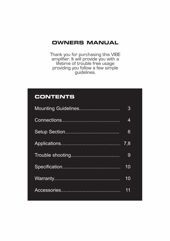
CONTENTS
Mounting Guidelines.............................. 3
Connections........................................... 4
Setup Section........................................ 6
Applications............................................ 7,8
Trouble shooting.................................... 9
Specification........................................... 10
Warranty................................................. 10
Accessories............................................ 11
OWNERS MANUAL
Thank you for purchasing this VIBEamplifier. It will provide you with a
lifetime of trouble free usage providing you follow a few simple
guidelines.

Mounting Guidelines
Your VIBE amplifier is designed with a swift installation routine in mind. Please mount the amplifier in a dry location on a solidsurface. NEVER mount the amplifier upside down, this will cause the amplifier to over heat and will eventually damage theamplifier. Before fixing the amplifier in place please ensure that there is sufficient air flow around the exterior of the casing,at least two inches is sufficient.
Connections
Power Cable
● At least an 8 gauge cable should be used for both the power and the ground connections to the amplifier. ● The power cable should be taken directly from the battery. Rubber grommets should be used when passing through
any bulkheads to prevent the cable from becoming chaffed or cut. ● It is vital that a fuse / circuit breaker (of at least equal value to the one fitted on the amplifier) is placed inline with the
power cable and is no further than eighteen inches away from the battery. ● Please ensure that the fuse is not fitted until the entire installation procedure is complete. ● The two tables below are to help you decide on what cable is correct for you. The first enables you to select the size of
cable depending on the length required. The second will help you convert the cable size from American Wire Gauge to Metric if you need to.
Length of Run
Current demand 0 – 4 Ft 4 – 7 Ft 7 – 10 Ft 10 – 13 Ft 13 – 16 Ft 16 – 19 Ft 19 – 22 Ft 22 – 28 Ft
0–20 amps 14 12 12 10 10 8 8 8
20–35 amps 12 10 8 8 6 6 6 4
35–50 amps 10 8 8 6 4 4 4 4
50–65 amps 8 8 6 4 4 4 4 2
65–85 amps 6 6 4 4 2 2 2 0
85–105 amps 6 6 4 2 2 2 2 0
105–125 amps 4 4 4 2 0 0 0 0
125–150 amps 2 2 2 0 0 0 0 0
AWG to Metric Conversion Chartcross sectional area
AWG Number Inch mm mm2
0 0.325 8.25 53.5 1 0.289 7.35 42.4 2 0.258 6.54 33.6 3 0.229 5.83 26.7 4 0.204 5.19 21.1 5 0.182 4.62 16.8 6 0.162 4.11 13.3 7 0.144 3.66 10.5 8 0.128 3.26 8.36 9 0.114 2.91 6.63 10 0.102 2.59 5.26
Ground Cable
● The ground cable needs to carry the same current as the power cable. At least an 8 gauge cable should be used. ● The amplifier ground should be connected directly to the chassis of the vehicle, to bare metal. ● The cable length should be kept to an absolute minimum. ● It is not recommended that you connect the ground cable to the vehicles seatbelts anchor point.
Remote Turn On
● A minimum of 18 gauge cable should be used for this connection. ● The cable should be run with exactly the same care and attention as the power cable and taken back to the source
(headunit) and joined to the remote cable provided. ● If the source (headunit) does not have a remote turn on cable then a 12v supply should be used. This will require a
switch to be fitted inline to enable the amplifier to be turned on and off. Remember that if this switch is left on you will flatten the car battery.
RCA Cables
● Depending on the model number of your amplifier and the number of speakers you wish to power you will have to run either one or two RCA cables from the source to the amplifier.
● Please take extra care when running these cables from the source to the amplifier. Ensure that they are placed away from all items that can generate any interference, wiring harnesses etc.
● It is recommended that the RCA cables should be run on opposite sides of the car to the previously installed power cables if possible, to avoid the cable picking up interferance.
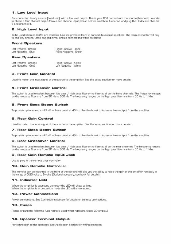
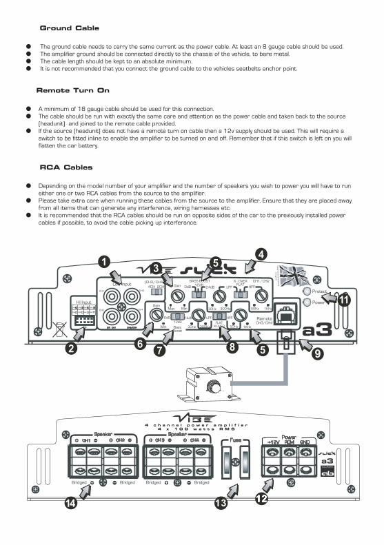
1. Low Level Input
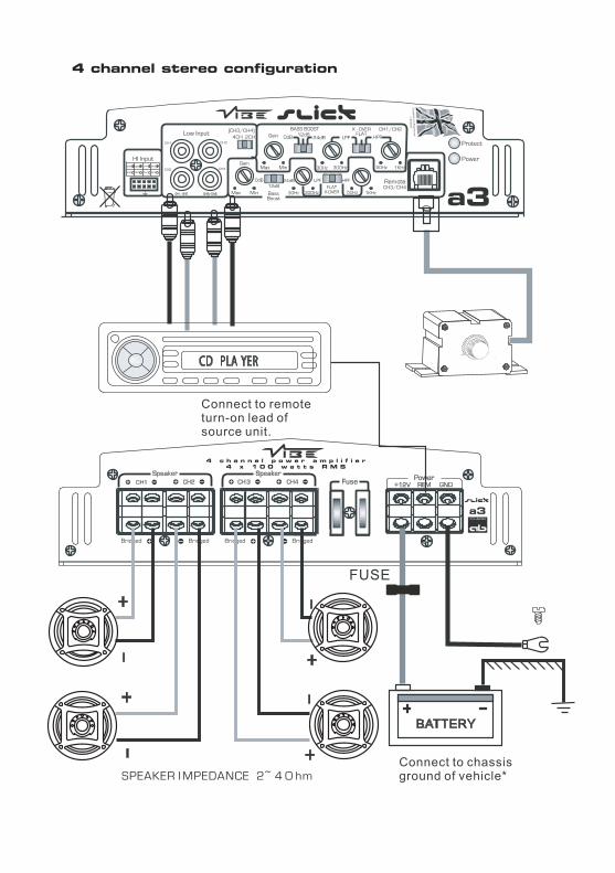
For connection to any source (head unit) with a low level output. This is your RCA output from the source (headunit). In orderto obtain a four channel output from a two channel input please set the switch to 4 channel and plug the RCA's into channel3 and channel 4.
2. High Level Input
To be used when no RCA's are available. Use the provided loom to connect to closest speakers. The loom connector will onlyfit one way around. Once plugged in you should connect the wires as below:
Front Speakers
Left Positive - Brown Right Positive - BlackLeft Negative - Blue Right Negative - Green
Rear Speakers
Left Positive - Orange Right Positive - YellowLeft Negative - Grey Left Negative - White
3. Front Gain Control
Used to match the input signal of the source to the amplifier. See the setup section for more details.
4. Front Crossover Control
The switch is used to select between low pass / high pass filter or no filter at all on the front channels. The frequency rangeson the low pass filter are from 30 Hz to 300 Hz. The frequency ranges on the high pass filter are from 50 Hz to 1 Khz.
5. Front Bass Boost Switch
To provide up to an extra +24 dB of bass boost at 45 Hz. Use this boost to increase bass output from the amplifier.
6. Rear Gain Control
Used to match the input signal of the source to the amplifier. See the setup section for more details.
7. Rear Bass Boost Switch
To provide up to an extra +24 dB of bass boost at 45 Hz. Use this boost to increase bass output from the amplifier.
8. Rear Crossover Control
The switch is used to select between low pass / high pass filter or no filter at all on the rear channels. The frequency rangeson the low pass filter are from 30 Hz to 300 Hz. The frequency ranges on the high pass filter are from 50 Hz to 1 Khz.
9. Rear Gain Remote Input Jack
Use to plug in the remote bass controller.
10. Gain Remote Controller
This remote can be mounted in the front of the car and will give you the ability to raise the gain of the amplifier remotely inthe range of 0.25 volts to 6 volts. (Optional accesory, see back for details)
11. Indicator LED
When the amplifier is operating correctly the LED will show as blue. When the amplifier is in protection mode the LED will show as red.
12. Power Connections
Power connections. See Connections section for details on correct connections.
13. Fuses
Please ensure the following fuse rating is used when replacing fuses: 30 amp x 2
14. Speaker Terminal Output
For connection to the speakers. See Application section for wiring examples.
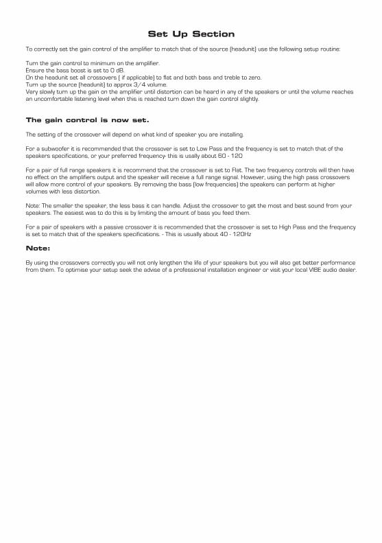
Set Up Section
To correctly set the gain control of the amplifier to match that of the source (headunit) use the following setup routine:
Turn the gain control to minimum on the amplifier.Ensure the bass boost is set to 0 dB.On the headunit set all crossovers ( if applicable) to flat and both bass and treble to zero.Turn up the source (headunit) to approx 3/4 volume.Very slowly turn up the gain on the amplifier until distortion can be heard in any of the speakers or until the volume reachesan uncomfortable listening level when this is reached turn down the gain control slightly.
The gain control is now set.
The setting of the crossover will depend on what kind of speaker you are installing.
For a subwoofer it is recommended that the crossover is set to Low Pass and the frequency is set to match that of thespeakers specifications, or your preferred frequency- this is usally about 60 - 120
For a pair of full range speakers it is recommend that the crossover is set to Flat. The two frequency controls will then haveno effect on the amplifiers output and the speaker will receive a full range signal. However, using the high pass crossoverswill allow more control of your speakers. By removing the bass (low frequencies) the speakers can perform at highervolumes with less distortion.
Note: The smaller the speaker, the less bass it can handle. Adjust the crossover to get the most and best sound from yourspeakers. The easiest was to do this is by limiting the amount of bass you feed them.
For a pair of speakers with a passive crossover it is recommended that the crossover is set to High Pass and the frequencyis set to match that of the speakers specifications. - This is usually about 40 - 120Hz
Note:
By using the crossovers correctly you will not only lengthen the life of your speakers but you will also get better performancefrom them. To optimise your setup seek the advise of a professional installation engineer or visit your local VIBE audio dealer.


Troubleshooting
● Before removing the amplifier, refer to the list below and follow the suggested procedures. ● Always test the speakers and confirm that they are wired correctly first. ● If in any doubt get help from a qualified auto electrician.
Amplifier Will Not Power Up
✓ Check for good ground connections. Ensure Ground cable is connected directly to bare metal and not a painted surface.
✓ Using a multimeter check that remote terminal has at least 7V DC.✓ Using a multimeter check that there is battery voltage on the positive terminal.✓ Check all fuses.✓ Check that the protection light is not illuminated. If it is lit, shut off the amplifier by Disconnecting for thirty seconds and
then turning it back on.
Protection LED Illuminates When Amplifier Is Powered Up
✓ Check for shorts on all speakers wires. (IE no speaker wires should be joined together and no speaker wires should be touching the cars chassis)
● The amplifier is designed to shut down automatically when the units temperature goes above 80 degrees. If the amplifier feels very hot then this may be the reason for the amplifier not starting.
● Remove the speaker wires and reset the amplifier. If the Protection LED still comes on then the amplifier is faulty. This damage may have been caused by either failure to follow these setup guidelines or abuse.
Amplifier Gets Very Hot
✓ Check the minimum speaker impedance for the amplifier is correct. ✓ Check for shorts on all speakers wires. (IE no speaker wires should be joined together and no speaker wires should be
touching the cars chassis)✓ Check that there is good airflow around the amplifier. In some applications an external fan may be required.
Blown Fuse(s)
✓ Check both positive supply and ground for shorts.✓ Check that the positive wire is connected to the positive terminal on the amplifier.✓ Check that the negative wire is connected to the ground terminal on the amplifier. ✓ Ensure that the correct rated fuse is fitted:
VIBE SLICK a3 –30 amp x 2,
Distorted Sound
✓ Check the gain control is not set at too high a level. If the speakers sound distorted turn the down the gain until the sound is clear.
✓ Check that all crossover frequencies are correct. See Setup section for more details. ✓ Check for shorts on all speaker wires. ✓ Check all speakers are wired correctly. With the correct polarity being observed on each connection.
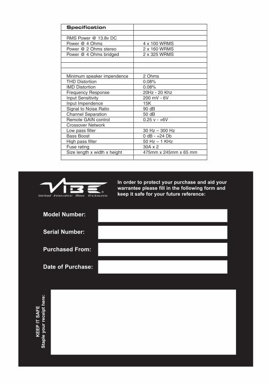
In order to protect your purchase and aid yourwarrantee please fill in the following form andkeep it safe for your future reference:
Model Number:
Serial Number:
Purchased From:
Date of Purchase:
KEE
PIT S
AFE
Stap
le y
our
rece
ipt h
ere:
Specification
RMS Power @ 13.8v DCPower @ 4 Ohms 4 x 100 WRMSPower @ 2 Ohms stereo 2 x 160 WRMSPower @ 4 Ohms bridged 2 x 325 WRMS
Minimum speaker impendence 2 OhmsTHD Distortion 0.08%IMD Distortion 0.08%Frequency Response 20Hz - 20 KhzInput Sensitivity 200 mV - 6VInput Impendence 15KSignal to Noise Ratio 90 dBChannel Separation 50 dBRemote GAIN control 0.25 v - +6VCrossover NetworkLow pass filter 30 Hz – 300 HzBass Boost 0 dB - +24 DbHigh pass filter 50 Hz – 1 KHzFuse rating 30A x 2Size length x width x height 475mm x 245mm x 65 mm
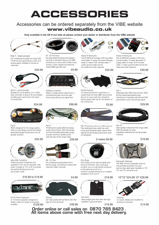
ACCESSORIESAccessories can be ordered separately from the VIBE website
www.vibeaudio.co.ukOnly available in the UK If out side uk please contact your dealer or distributer from the VIBE website
Order online or call sales on 0870 765 8423 . All items above come with free next day delivery.
PC10 Power CapacitorA 1.0 Farad capacitor designed todeliver maximum power to any bassamplifier.
GB - 41 PlusOur professional gold plated 4mmbanana plugs, are polarity marked withcoloured rubber shrouds.
FastplugIs a quick release car amplifier toenclosure connector
Alloy CNC TurboPortThese exclusive TurboPorts areavailable in 2.5" and 3" diameter, witheither a length of 1.5" or 6" to providethe perfect finishing touch forany custom build.
Flat Y - Interconnect Our professional quality full range OCCY-interconnect guarantees a pure andstrong signal. Available in female tomale also.
GT - 2V TerminalOur gold plated binding post speakerterminal is standard issue on all VIBEenclosures, it comes with 5 Allen headscrews, a foam gasket and featuresraised VIBE logo with text.
Power 8 Wiring KitThis 8 AWG kit includes a 60 amp AGUfuse holder, 5 meter flat power 8supplycable, 5 meter FLAT remote cable, 1meter ground cable and allthe cable terminals required.
Power 4 Wiring KitThis 4 AWG kit includes a 100 ampcircuit breaker, 5 meter flat power 4supply cable, 5 meter FLAT remotecable, 1 meter ground cable and all thecable terminals required.
BC10 - Level ControllerSuitable for all amplifiers, our in dashlevel controller is easy to fit and enablesamplifier gain control from the dashmounted lever.
Deltabox LinedriverAllows a single stereo output from aconventional head unit to be splitthree ways without any signal loss.
FK-28 Fixing KitTo reduce enclosure movement in acarpet lined car boot VIBE recommendthis kit. It comes with four industrialVelcro pieces with tac for the bottom ofthe enclosures.
Flat 1Dedicated bass RCA interconnect. Withferrite loaded gold plated plugs,interference is greatly reduced and OCCguarantees a pure and strong signal.
Flat 2RCA's designed for full range signals.With our flat design and ferrite loadedgold plated plugs interference can begreatly reduced.
Flat 3Professional quality OCC flat designaudio interconnect. OCC technologyand ferrite loaded gold plated plugsprovide reference quality soundwith this top of the range cable.
Flat 13 (standard cable for any VIBE enclosure)
This dedicated bass cable has solidcores guaranteeing higher power basssignals. Its flat design guarantees easeof installation.
Flat 16High quality multi-strand full range cable.With flat design for easyinstallation.interference can be greatlyreduced.
Fleeces.Our high quality half zip fleece with vibelogo on front and back
Polo Shirtheavy weight polo shirt with vibe logoavailable in gray and black
Port PlugsPort Plugs can be used to tightly sealthe port chamber. Use a port plugto either tune a multi ported enclosureto the desired sound or toconvert a ported enclosure to a sealed.Available in 2.5" and 3"
Subwoofer DefenderThe VIBE chrome subwoofer grill notonly provides protection for yoursub but also adds style. Available in 10",12" and 15" versions to fit
£29.99 £5.99 £24.99 £49.99
£24.99 £99.99 £3.99 £29.99
£24.99 £29.99 3 metre £9.99 £19.99
£16.99 to £19.99 £4.99 £19.99 10”12” £24.99 15” £29.99
£129.99 £49.99 £19.99 £14.99

Copyright
All content included in this manual such as text, graphics, logos, icons, images and data, are the property of VIBETechnologies Limited (herein referred to as "VIBE", "us" or "we") and its affiliate or their content and technology providers,
and are protected by United Kingdom and International copyright laws. All rights reserved.
All stylised representations of product names, or the abbreviations of product names, as logos are all trademarks ofVIBE. Graphics and logos are trademarks or trade dress of VIBE Technologies Ltd or its subsidiaries.
VIBE's trademarks and trade dress may not be used in connection with any product or service that is not VIBE's, in anymanner that is likely to cause confusion among customers or in any manner that disparages or discredits VIBE. All othertrademarks not owned by VIBE or its subsidiaries that appear in this manual are the property of their respective owners,
who may or may not be affiliated with, connected to, or sponsored by VIBE or its subsidiaries.
TO THE FULLEST EXTENT PERMITTED AT LAW, VIBE IS PROVIDING THIS MANUAL AND ITS CONTENT ON AN"AS IS" BASIS AND MAKES NO (AND EXPRESSLY DISCLAIMS ALL) REPRESENTATIONS OR WARRANTIES OF
ANY KIND, EXPRESS OR IMPLIED, WITH RESPECT TO THIS MANUAL OR THE INFORMATION, CONTENT,MATERIALS OR PRODUCTS INCLUDED IN THIS MANUAL INCLUDING, WITHOUT LIMITATION, WARRANTIES OF
MERCHANTABILITY AND FITNESS FOR A PARTICULAR PURPOSE.IN ADDITION, VIBE DOES NOT REPRESENT OR WARRANT THAT THE INFORMATION CONTAINED IN THIS
MANUAL IS COMPLETE OR CURRENT, AND THAT ALL SPECIFICATIONS AND INFORMATION CONTAINED WITHINTHIS MANUAL ARE SUBJECT TO CHANGE WITHOUT NOTICE.
VIBE RECOMMEND CAUTION WHEN LISTENING TO MUSIC REPRODUCED THROUGH VIBE EQUIPMENT. VIBEEQUIPMENT IS CAPABLE OF PRODUCING SOUND AND SOUND PRESSURE LEVELS THAT CAN PERMANENTLY
DAMAGE HEARING OF YOU AND THAT OF OTHERS. FOR SAFE AND ENJOYABLE LISTENING, THE SOUNDSHOULD BE CLEAR WITHOUT DISTORTION AT A COMFORTABLE VOLUME.
BY USING ANY VIBE EQUIPMENT, YOU AGREE TO TAKE FULL RESPONSIBILITY FOR YOUR OWN SAFETY ANDTHE SAFETY OF OTHERS WHEN LISTENING TO MUSIC AT HIGH VOLUMES THROUGH EQUIPMENT YOU HAVE
PURCHASED. USE OF ANY VIBE EQUIPMENT CONSTITUTES AGREEMENT TO THIS DISCLAIMER.Except as specifically stated in this manual, to the fullest extent permitted at law, neither VIBE nor any of its affiliates,
directors, employees or other representatives will be liable for damages arising out of or in connection with the use of thismanual or the information, content, materials or products included.
This is a comprehensive limitation of liability that applies to all damages of any kind, including (without limitation)compensatory, direct, indirect or consequential damages, loss of data, income or profit, loss of or damage to property andclaims of third parties. For the avoidance of doubt, VIBE does not limit its liability for death or personal injury to the extent
only that it arises as a result of negligence of VIBE, its affiliates, directors, employees or other representatives.
Limited Warranty
All VIBE products carry a full twelve months warranty, valid fromthe date of the original receipt proof of purchase. In order to
validate this warranty, the warranty card should be returned to VIBEwithin seven days of the original purchase date. The original receipt
and packaging are should also be retained for this twelve month period.
If at any stage during the warranty period you have a problem with theproduct then it should be returned to the point of purchase, in its
original packaging, complete with no items missing.
If the store is unable to fix the product it may have to be returned toVIBE this process takes around 7 working days.
A full description of VIBE's warranty information can be found on ourwebsite:
www.vibeaudio.co.uk/warranty
A written version can also be obtained fromVIBE warranty Dept
PO BOX 11000B75 7WG