VI. TECHNOLOGY SELECTION AND PRODUCT ACQUISITION
45
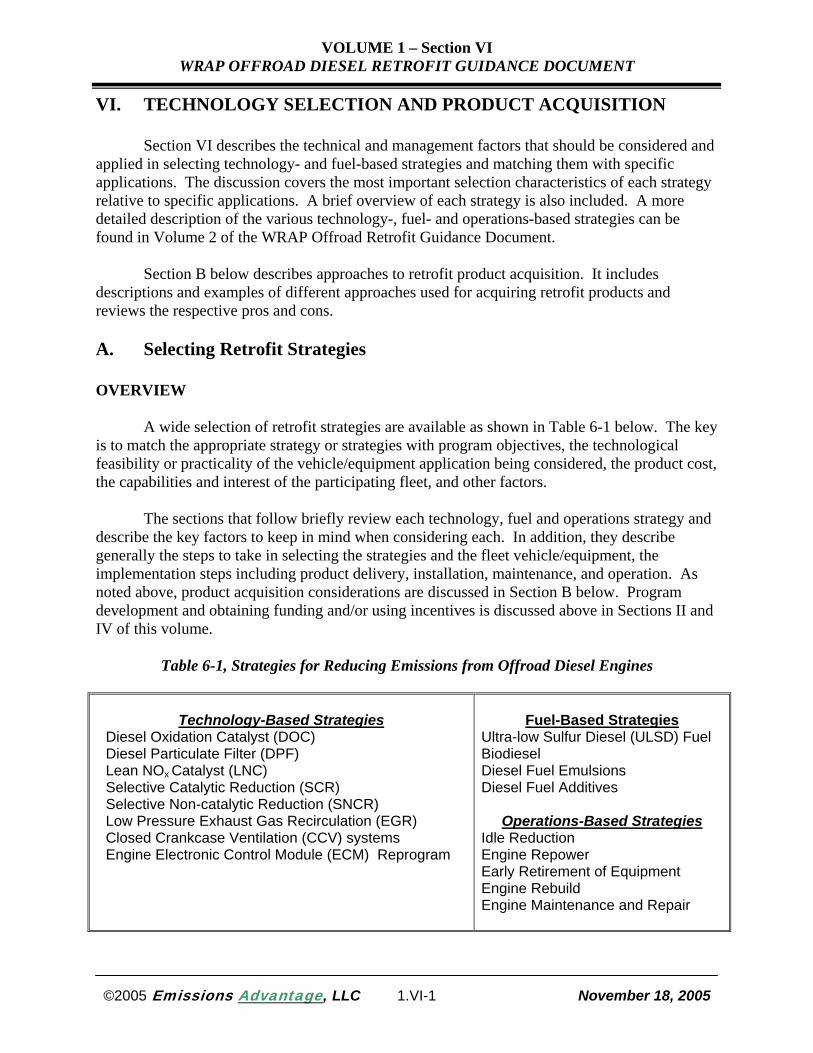
VOLUME 1 – Section VI WRAP OFFROAD DIESEL RETROFIT GUIDANCE DOCUMENT VI. TECHNOLOGY SELECTION AND PRODUCT ACQUISITION Section VI describes the technical and management factors that should be considered and applied in selecting technology- and fuel-based strategies and matching them with specific applications. The discussion covers the most important selection characteristics of each strategy relative to specific applications. A brief overview of each strategy is also included. A more detailed description of the various technology-, fuel- and operations-based strategies can be found in Volume 2 of the WRAP Offroad Retrofit Guidance Document. Section B below describes approaches to retrofit product acquisition. It includes descriptions and examples of different approaches used for acquiring retrofit products and reviews the respective pros and cons. A. Selecting Retrofit Strategies OVERVIEW A wide selection of retrofit strategies are available as shown in Table 6-1 below. The key is to match the appropriate strategy or strategies with program objectives, the technological feasibility or practicality of the vehicle/equipment application being considered, the product cost, the capabilities and interest of the participating fleet, and other factors. The sections that follow briefly review each technology, fuel and operations strategy and describe the key factors to keep in mind when considering each. In addition, they describe generally the steps to take in selecting the strategies and the fleet vehicle/equipment, the implementation steps including product delivery, installation, maintenance, and operation. As noted above, product acquisition considerations are discussed in Section B below. Program development and obtaining funding and/or using incentives is discussed above in Sections II and IV of this volume. Table 6-1, Strategies for Reducing Emissions from Offroad Diesel Engines Technology-Based Strategies Diesel Oxidation Catalyst (DOC) Diesel Particulate Filter (DPF) Lean NO x Catalyst (LNC) Selective Catalytic Reduction (SCR) Selective Non-catalytic Reduction (SNCR) Low Pressure Exhaust Gas Recirculation (EGR) Closed Crankcase Ventilation (CCV) systems Engine Electronic Control Module (ECM) Reprogram Fuel-Based Strategies Ultra-low Sulfur Diesel (ULSD) Fuel Biodiesel Diesel Fuel Emulsions Diesel Fuel Additives Operations-Based Strategies Idle Reduction Engine Repower Early Retirement of Equipment Engine Rebuild Engine Maintenance and Repair ©2005 Emissions Advantage , LLC 1.VI-1 November 18, 2005
Transcript of VI. TECHNOLOGY SELECTION AND PRODUCT ACQUISITION
VOLUME 1 – Section VI WRAP OFFROAD DIESEL RETROFIT GUIDANCE DOCUMENT
VI. TECHNOLOGY SELECTION AND PRODUCT ACQUISITION Section VI describes the technical and management factors that should be considered and applied in selecting technology- and fuel-based strategies and matching them with specific applications. The discussion covers the most important selection characteristics of each strategy relative to specific applications. A brief overview of each strategy is also included. A more detailed description of the various technology-, fuel- and operations-based strategies can be found in Volume 2 of the WRAP Offroad Retrofit Guidance Document.
Section B below describes approaches to retrofit product acquisition. It includes descriptions and examples of different approaches used for acquiring retrofit products and reviews the respective pros and cons. A. Selecting Retrofit Strategies OVERVIEW
A wide selection of retrofit strategies are available as shown in Table 6-1 below. The key is to match the appropriate strategy or strategies with program objectives, the technological feasibility or practicality of the vehicle/equipment application being considered, the product cost, the capabilities and interest of the participating fleet, and other factors. The sections that follow briefly review each technology, fuel and operations strategy and describe the key factors to keep in mind when considering each. In addition, they describe generally the steps to take in selecting the strategies and the fleet vehicle/equipment, the implementation steps including product delivery, installation, maintenance, and operation. As noted above, product acquisition considerations are discussed in Section B below. Program development and obtaining funding and/or using incentives is discussed above in Sections II and IV of this volume.
Table 6-1, Strategies for Reducing Emissions from Offroad Diesel Engines
Technology-Based Strategies Diesel Oxidation Catalyst (DOC) Diesel Particulate Filter (DPF) Lean NOx Catalyst (LNC) Selective Catalytic Reduction (SCR) Selective Non-catalytic Reduction (SNCR) Low Pressure Exhaust Gas Recirculation (EGR) Closed Crankcase Ventilation (CCV) systems Engine Electronic Control Module (ECM) Reprogram
Fuel-Based Strategies
Ultra-low Sulfur Diesel (ULSD) Fuel Biodiesel Diesel Fuel Emulsions Diesel Fuel Additives
Operations-Based Strategies Idle Reduction Engine Repower Early Retirement of Equipment Engine Rebuild Engine Maintenance and Repair
©2005 Emissions Advantage, LLC 1.VI-1 November 18, 2005

VOLUME 1 – Section VI WRAP OFFROAD DIESEL RETROFIT GUIDANCE DOCUMENT
In selecting a retrofit technology, it is critical to select a product that has been well demonstrated for the particular vehicle or equipment being retrofitted. This selection process is greatly facilitated by the fact that both the U.S. EPA and California’s Air Resource Board have established rigorous technology verification procedures. Products verified under these programs have undergone extensive emission reduction evaluations and durability demonstrations. Using EPA and/or CARB verified products where they are applicable is highly recommended. In those instances where a verified product is not available for a particular engine application, consulting first with CARB and/or EPA is recommended INDIVIDUAL STRATEGY REVIEW AND APPLICATION CONSIDERATIONS
Technology-Based Strategies
Diesel Oxidation Catalysts (DOC)
DOC Technology Overview – DOCs have been in commercial use since the late1960s in offroad applications and since the 1980s in on-road applications. This technology has a proven track record of excellent performance. In on-road OE applications, over 50 million passenger cars and over three million trucks and buses have been equipped with DOCs. Worldwide, over 200,000 trucks and buses have been retrofitted with DOCs. In addition, 250,000 new and existing offroad engines have been equipped. The types of offroad equipment retrofitted with DOCs includes mining equipment (e.g., excavators), construction equipment (e.g., skid steer loaders, dump trucks, rubber tire loaders, excavators), materials handling equipment (e.g., forklifts), utility equipment (e.g., street sweepers, tractors), agricultural equipment (e.g., irrigation pumps), and marine vessels (e.g. passenger ferries). DOCs have been used on offroad engines ranging from less than 75 hp (e.g., forklifts) to over 750 hp (e.g., large passenger ferries in Hong Kong and large stationary engines in California).
Retrofitting engines with DOCs is extremely popular because the technology has near
universal application, is easily installed, requires virtually no maintenance, does not adversely impact vehicle performance or fuel consumption, achieves emission reductions in a cost-effective manner, and can operate effectively on fuels with 500 ppm sulfur and higher depending on the application and the pollutant(s) to be controlled.
DOCs consist of a ceramic or metallic substrate coated with a catalyst formulation and encased in a stainless steel canister. The exhaust pollutants flow through the catalyst substrate and are chemically transformed on the active metal sites to CO2 and water. DOCs control PM
©2005 Emissions Advantage, LLC 1.VI-2 November 18, 2005

VOLUME 1 – Section VI WRAP OFFROAD DIESEL RETROFIT GUIDANCE DOCUMENT
exhaust emissions by 20% to 50% depending on the engine exhaust temperature, the sulfur level in the fuel, the composition of the engine-out PM, and other factors. This technology also controls HC and CO up to 90%, as well as reducing diesel smoke and virtually eliminating diesel odor. Also, in cases where DOCs are used a muffler replacement, the noise attenuation of the DOCs meets or exceeds the specification of the OE muffler being replaced.
DOCs in retrofit applications range from less than $500 to $1,250 for engines in the 100-
200 horsepower category, and from less than $1,000 to $1,750 for engines in the 200-500 horsepower category.
DOC Application Considerations – In considering DOC technology, a number of factors
should be considered including: 1. DOC Emissions Control Performance. DOCs control the soluble organic fraction of
the PM by up to 90%. The PM SOF from a diesel engine is related, in part, to the engine lubricant consumption and in-cylinder combustion characteristics of that diesel engine. Older offroad engines typically have a higher concentration of SOF, due to high lubricating oil consumption, compared to new on-road vehicles, making DOCs a particularly effective application for these offroad engines. On newer engines, where the SOF fraction is quite low, DOCs may not be a good choice. DOC technology is not effective in reducing the carbon-based particles, including the ultra-fine fraction of the PM. DOCs do not impact the level of NOx emissions and, since DOCs typically do not adversely impact fuel consumption, they do not affect the level of CO2 emissions.
2. DOC Application Experience. DOCs have the greatest application experience of any
retrofit strategy, having been installed on trucks, buses, passenger cars, and offroad equipment including mining equipment, construction equipment, utility equipment, locomotives and marine vessels. Several DOCs designs have been verified by EPA and CARB for on-road and to a limited extent for offroad applications.
3. DOC Application Criteria. With very limited exceptions, DOC technology can be
applied to virtually any type and size of diesel-powered engine. The only potentially limiting factors are: 1) available space on the vehicle/equipment (this is less of an issue with DOCs since in most cases its dimensions are the same size as the muffler it replaces), 2) older engines with extremely high PM emissions levels, and 3) vehicles/equipment that operate in very cold ambient temperatures and idle for extended periods.
DOC performance is not reduced significantly when used with conventional low sulfur
content (up to 300 ppm to 500 ppm) diesel fuel. However, the amount of sulfate, and in turn the amount of total PM measured will increase as the sulfur content increases. Consequently, the emission control performance of a DOC is enhanced if it is operated with ULSD with a maximum sulfur content of 15 ppm.
4. DOC Installation/Maintenance. Installation is typically very straightforward and usually requires one to two hours. Maintenance is rarely, if ever, required. Nevertheless, care should be taken in: 1) selecting and preparing vehicles/equipment for retrofit, 2) installing the
©2005 Emissions Advantage, LLC 1.VI-3 November 18, 2005
VOLUME 1 – Section VI WRAP OFFROAD DIESEL RETROFIT GUIDANCE DOCUMENT
DOCs, and 3) periodically checking the DOC, the installation hardware and exhaust system for physical damage. Installation is often performed, after receiving training, by fleet personnel. If the DOC is equipped on a vehicle/equipment with high PM levels, installing a backpressure monitor is recommended and periodic cleaning of the DOC may be necessary to remove built-up ash and other combustion by-products.
5. DOC Operating Experience. The overall experience with DOCs in retrofit applications during the past 30 years has been outstanding. This technology has been the most popular retrofit choice to date because of several factors including:
• Virtually universal application • Easy installation
• No technology maintenance
• Ability to be used on vehicles/equipment fueled with conventional diesel fuels
• Lower cost compared to other retrofit technologies
• No operational issues, impacts on vehicle/equipment performance or impacts on fuel
consumption DOCs in both on-road and offroad applications have demonstrated effective emission
reduction performance over extended periods. DOCs routinely last the remaining life of the engine until rebuild.
6. DOC Issues and Solutions. Problems with DOCs have been very rare. Where they have occurred, they tended to involve such issues as an improper DOC design configuration for a particular vehicle/equipment application or failure to provide the correct installation hardware. These type of issues can be easily addressed by close coordination and planning between the DOC supplier and the vehicle/equipment fleet personnel. DOC plugging has occurred on very rare occasions and typically involved older, high oil consumption engines that may operate at idle for expended periods of time and/or operate in areas with very cold ambient temperatures.
7. DOC Impacts on Vehicle Performance. Decades of experience indicate that DOCs do not have any adverse impacts on engine performance. With regard to fuel economy, studies conducted over the years, generally, have reported that either DOCs have no impact on fuel economy consumption. In those cases in which a slight decrease was measured, it was not considered statistically significant.
©2005 Emissions Advantage, LLC 1.VI-4 November 18, 2005

VOLUME 1 – Section VI WRAP OFFROAD DIESEL RETROFIT GUIDANCE DOCUMENT
Diesel Particulate Filters (DPFs)
DPF Technology Overview – DPFs are commercially available and used both as OE on
passenger cars (over 1,000,000) in Europe, on transit buses in the U.S. and elsewhere, and as a retrofit technology on well over 200,000 on-road vehicles and offroad equipment worldwide.
The DPF system consists of a filter encased in a stainless steel canister that is positioned
in the exhaust stream and is designed to collect particulate emissions while allowing the exhaust gases to pass through the system. A DPF system has three main components: 1) the filter that collects or “traps” the PM, 2) a means for removing the PM from the filter (a “filter regeneration strategy”) and 3) a mechanism for determining whether engine back pressure is increasing due to the build-up of ash and other constituents on the filter surfaces.
DPFs are often categorized as either “passive” or “active” depending on the method used
to achieve filter regeneration. A passive DPF is one in which the filter regenerates in normal vehicle/equipment operation without any additional assistance. Examples of passive DPFs are filters coated with a catalytic material, a diesel oxidation catalyst upstream of the DPF, and a fuel-borne catalyst (FBC) used in combination with a filter. An active DPF system relies on additional strategies to ensure that filter regeneration occurs. Examples of active DPFs are ones that employ engine modifications, fuel injection, on-board burners or heaters, or off-board electrical heaters.
The advantages of passive systems are that they are technologically less complex, require
far less servicing, and are less expensive than active systems. The advantages of active systems are that they will function effectively even if the desired exhaust temperatures are not achieved in normal operation and consequently, they can be employed in applications (e.g., vehicles/equipment with low exhaust temperatures) on which passive filters cannot used.
DPFs have demonstrated the capability to reduce PM by up to 90% or more, and have the
capability of reducing total carbon-based particulates by over 99%, including ultra-fine carbon particles. Those DPFs that employ a catalyst component are capable of reducing HC and CO by up to 90%. This technology also reduces or eliminates smoke and odor from a diesel engine. DPFs do not impact total NOx emissions and most DPF designs have little or no impact on fuel economy.
©2005 Emissions Advantage, LLC 1.VI-5 November 18, 2005

VOLUME 1 – Section VI WRAP OFFROAD DIESEL RETROFIT GUIDANCE DOCUMENT
Other types of DPFs include both those that use disposable filters and flow-through filters
(FTF). The disposable filter is designed to collect the amount of PM that is likely to be generated during a working shift or two of operation while remaining within the engine manufacturer’s backpressure specification. The filter is then removed and properly disposed. This technology is limited to low-temperature environments. Disposable filters have been used on underground mining equipment, construction equipment and forklifts. A relatively new type of DPF system, often referred to as a “flow-through filter” (FTF), has emerged that does not trap the PM like the conventional DPFs discussed above, but instead is designed to provide exhaust flow turbulence and increased PM residence time. Several different design types are emerging, including wire mesh filter, pertubated path metal foil filter, and others. This technology also has been referred to “high-efficiency DOCs”, “partial flow DPFs”, “DPFs”, and “wire mesh DOCs”.
DPFs sold for use on-road vehicle applications have generally fallen within the $5,000 to
over $10,000 range. The estimated costs of flow-through filters typically falls somewhere in the range between the cost of conventional DPFs and DOCs (e.g., approximately in the $3,000 range). Information on the cost of DPF hardware for offroad applications is very limited, but the costs are expected to be comparable to, if not somewhat higher than, on-road applications of similar size and horsepower ratings.
DPF technology is application specific. This means that before the technology can be applied to a given vehicle or piece of equipment, certain prerequisites most be met Considerable care is needed in determining whether a DPF is a good fit for a particular application. DPFs also require more maintenance and performance monitoring than other technologies such as DOCs.
DPF Application Considerations – In considering DPF technology for use in retrofit programs, several factors should be considered including:
1. DPF Emission Control Performance. DPFs are the most effective PM emission control strategy available. They are capable of reducing total PM by 85% to over 90%, and the carbon-based particles, ultra-fines by over 99%. Catalyst-based DPFs reduce CO and HCs, including toxic HC like PAHs, Nitro-PAHs, and benzene by up to 90%. While DPFs generally do not have an impact on total NOx emissions, one NOx-related issue has arisen with those catalyst-based DPFs designed to generate NO2 in order to facilitate the oxidation of PM. Studies have found that this type of DPF system design can increase the NO2 fraction of the total NOx emitted from the tailpipe. Studies have reported percentage increases of the NO2 fraction of the total NOx emitted ranging from 6% to approximately 35%. The varying degree of increased NO2 from these DPF systems may be attributable to specific design features, different type engines, mileage accumulation and other factors. Technology providers are making progress in developing strategies to minimize NO2 production, including improvements in system design and catalyst formulations.
Flow-through filters have achieved PM reductions of 40% to more than 65%. While these
levels are well below the PM control levels achieved by the conventional DPFs (over 90% PM reduction), they do have a broader application than the conventional DPF.
©2005 Emissions Advantage, LLC 1.VI-6 November 18, 2005

VOLUME 1 – Section VI WRAP OFFROAD DIESEL RETROFIT GUIDANCE DOCUMENT
2. DPF Application Experience. Limited DPF retrofit demonstrations began in the
1980s, primarily on offroad applications such as mining equipment, and continued in the early 1990s, expanding to transit bus applications as well. In the late 1990s and early 2000s, the number of retrofit programs and vehicles/equipment retrofitted grew significantly. Today, well over 200,000 DPFs have been retrofitted on on-road and offroad engines. Offroad DPF applications include forklifts, dump trucks, wheel loaders, cranes, generators, marine vessels and locomotives. In addition, a large number of new on-road vehicles have been and are scheduled to be equipped with DPFs as original equipment. DPFs can be combined with NOx control technologies such as LNC, SCR technology and low-pressure EGR systems to provide significant PM and NOx emission reductions. Several DPFs have been verified for on-road applications and limited offroad applications by both EPA and/or CARB.
3. DPF Application Criteria. DPFs are an application specific technology. A case-by-
case determination is necessary. In making a decision to use DPF in a particular engine application, the following factors must be considered: 1) the level of engine-out emission levels, including those from the engine lubricating oil, 2) the engine operating exhaust temperature profile, 3) available space to equip the DPF, and 4) the level of sulfur in the diesel fuel.
a. High PM Levels. If the level of engine-out PM emissions, including those from the
engine lubricating oils are sufficiently high, the volume of PM reaching the DPF can overwhelm the ability of the DPF system to remove the PM collected in the filter before it accumulates and plugs the filter. High PM levels are a greater issue with passive DPF systems, but can be a factor in employing active DPF systems as well. High PM levels also can be an issue in applying higher efficiency flow-through filters. For flow-through filters, the application criteria vary based on the level of the PM control efficiency. At the lower PM control efficiencies, FTFs have very wide application, much like a DOC. At higher PM control efficiencies, this technology is applied on a case-by-case basis.
b. Minimum Exhaust Temperatures. Passive DPF systems, such as catalyst-based
systems, whose ability to properly destroy PM in the filter is influenced by the engine exhaust temperature, can only be employed if minimum exhaust temperatures for a given period are achieved (temperature/time requirement). While the application range for flow-through filters can be greater than conventional DPFs, exhaust temperatures are still a consideration that must be evaluated. To properly assess the applicability of a DPF, the exhaust temperatures of the candidate vehicles/equipment should be data logged over a worst-case operating scenario in terms of low- or no-load operation, stop-and-go driving, time at idle, and when possible, the colder ambient temperatures that are likely to occur during the year. If the operating exhaust temperatures are too low to enable the passive system to regenerate, PM will accumulate in the filter increasing backpressure and eventually adversely affecting engine performance. Subsequently, the DPF could fail. There is no one temperature/time minimum that can be applied to all passive DPFs systems for all applications. Rather, the required temperature/time minimum needed will vary based on the design of the DPF and the engine application. When applying DPF technology, the technology vendor should be consulted to determine whether the exhaust temperatures will be adequate to support regeneration.
c. Appropriate NOx Ratio. The NOx/PM ratio in the engine-out exhaust emission ratio
must match the specifications of the manufacturer if a catalyst-based DPF system is used.
©2005 Emissions Advantage, LLC 1.VI-7 November 18, 2005

VOLUME 1 – Section VI WRAP OFFROAD DIESEL RETROFIT GUIDANCE DOCUMENT
d. Available Space on the Vehicle/Equipment. In some instances a DPF may have larger
dimensions and/or weigh more than the muffler it replaces. An important consideration in applying DPF technology is to ensure that adequate space is available on the vehicle/equipment to properly install the DPF. Making this determination involves several factors:
• Does adequate space exist in the exhaust system to install the device at the appropriate
place to provide optimum performance?
• Does access exist to easily inspect and remove the DPF for cleaning?
• Can the DPF be installed without adversely impacting the operation of the vehicle or impacting the safety of the operator?
e. Level of Sulfur in the Fuel. DPF systems that do not employ catalyst-based strategies
and rely on external sources for filter regeneration have operated effectively on engines fueled with diesel fuel containing 500 ppm sulfur or, in limited cases high sulfur levels (e.g., underground mining equipment in Canada). Those passive and active DPF systems that employ catalyst-based strategies are adversely affected by the level of sulfur in the fuel.
Sulfur affects filter performance by inhibiting the performance of catalyst materials
upstream of, or on, the filter. This phenomenon not only adversely affects the ability to reduce emissions, but it also adversely impacts the capability of these filters to regenerate. A direct trade-off exists between sulfur levels in the diesel fuel and the ability to regenerate the filter. Sulfur also competes with the catalytic reactions intended to reduce pollution and further creates PM through catalytic sulfate formation.
The vast majority of DPF retrofit projects in the U.S. and Europe use diesel fuel with
sulfur levels less than 15 ppm. The use of this very low sulfur fuel enables filters to use catalytic formulations designed for maximum filter regeneration, for the highest levels of PM reductions, and for the least amount of sulfate generation. The use of diesel fuel with a maximum of 15 ppm sulfur content has been a key factor in the success of many program in terms of enhancing filter durability, performance and extended cleaning intervals. Retrofit projects in the U.S. employing flow-through filters on such applications as school buses, transit buses and construction cranes are operating on conventional highway diesel fuel containing less than 500 ppm sulfur. 4. DPF Installation/Maintenance. Application and use of DPF technology requires careful engine screening and preparation, regular checking of monitoring equipment, proper engine maintenance, and periodic cleaning of the filter element.
a. Pre-Installation Procedures. Prior to installation, vehicles/equipment should be inspected (both the engine and the exhaust system) and any routine or necessary maintenance performed. This includes checking engine components and, replacing if necessary, such components as fuel injectors (warn injectors can leak fuel into the combustion chamber causing excess PM to collect on the filter) and the turbocharger (turbocharger failure can lead to excess engine lubricant and/or fuel being supplied to the filter which in turn can cause a catastrophic DPF failure).
©2005 Emissions Advantage, LLC 1.VI-8 November 18, 2005

VOLUME 1 – Section VI WRAP OFFROAD DIESEL RETROFIT GUIDANCE DOCUMENT
b. DPF Installation. The complexity of DPF installation can vary considerably. In some
cases, installation is a relatively straightforward muffler replacement. In other cases, it is more complex because of such factors as limited space to locate the DPF and/or difficulty in accessing and working in the space where the DPF will be fitted. Also, the design of the inlet and outlet of the DPFs and connecting hardware will vary depending on the specific application. In some cases, modifications to the existing exhaust system will be needed. The time needed to perform a DPF installation can vary from as few as two hours to 10 or more hours, depending on the complexity of the installation. Installation is typically performed by the technology provider.
DPFs are often heavier and/or larger than the mufflers they replace. Therefore, care must
be taken to ensure that the installation hardware has sufficient strength to support the DPF. Failure to use the appropriate hardware can result in mechanical failure of clamps and brackets and can result in damage to the DPF. Special quick-release brackets are often utilized to facilitate quick removal of the filter for cleaning. Also, unless the exhaust temperatures are clearly sufficient with a large margin safety, insulation of the engine compartment, the DPF, and/or the exhaust pipe between the engine and inlet of the DPF is recommended.
c. DPF Maintenance. The principal maintenance item for DPFs is the periodic cleaning of the filter. Also, periodic visual inspection is recommended for: 1) the DPF assembly hardware to ensure the DPF is still firmly connected, 2) the outer shell of the DPF for physical damage, and 3) the exhaust system for leaks.
Filters need to be cleaned periodically because under normal operating conditions, the
filter collects the PM and periodically oxidizes the carbon-based PM. Inorganic material, such as phosphorus, sulfur, calcium, and zinc, derived from the lubricating oil, the sulfur in the fuel, uncompensated organic PM, and residue from engine wear will also be collected on the filter. These materials can form oxides and sulfate materials that remain on the filter. Overtime, these materials accumulate on the filter, eventually causing a pressure increase across the filter and the engine exhaust backpressure to increase.
Filter cleaning should be performed in accordance with the technology manufacturer’s
recommend maintenance schedule or when the backpressure monitor/alarm indicates engine backpressure levels are approaching or exceeding the engine manufacturer’s specifications. Recommended cleaning intervals vary widely based on such factors as engine age, engine lubricating oil consumption, engine lubricating oil composition, whether a FBC is used, vehicle/equipment application, and engine operating cycles. Recommended intervals are typically stated in terms of number of days/mile or hours of operation, which ever occurs first (e.g., annually or every 20,000 miles). In most applications, cleaning at least annually is recommended.
Several different types of filter cleaning methods can be employed, including using a
combination of a pressurized air gun on one end to clean the filter and an industrial vacuum device at the other end to collect the ash (one hour duration). Additionally, heating/baking the filter by placing it in an industrial oven or by using a stand-alone cleaning unit that includes a heating element to burn-off any organic soot remaining on the filter (8 to 12 hours) can also be used. The DPF manufacturer will specify the types of cleaning that are appropriate for its DPF design and the engine application.
©2005 Emissions Advantage, LLC 1.VI-9 November 18, 2005

VOLUME 1 – Section VI WRAP OFFROAD DIESEL RETROFIT GUIDANCE DOCUMENT
Ash and other materials removed from the filter should be collected and disposed of in an
environmentally appropriate matter. Workers and others should not be exposed to airborne ash – using a vacuum device with a sealed container to collect ash is one example of an effective cleaning/collection technique. In some jurisdictions, DPF waste ash is considered to be a hazardous material, while in others, it is treated as dry industrial waste. State and local environmental agencies are good sources for determining how DPF waste ash should be treated.
5. DPF Operating Experience. The overall experience with both active and passive
DPFs in both on-road and offroad applications has been very good. When properly constructed, applied, maintained, and fueled, DPFs have demonstrated high PM control efficiencies for extended periods. In those instances were applications of passive DPFs were successful in terms of emission control performance, system durability, and minimum maintenance, several common factors were present, including:
• Newer, well-maintained engines with low engine lubricating consumption. • Engines fueled with ULSD.
• Operating exhaust temperature profiles were well above the minimum time/temperature
specified by the technology provider. 6. DPF Issues and Solutions. The most frequent problem associated with DPF
technology is the plugging of the filter with PM, which in some cases can lead to a filter failure. Other DPF failures have involved canning failures (filter cracks), improper installation (resulting in excess vibration causing mechanical failure), filter media failures (e.g., cementing failures in multi-section filters). The causes of filter plugging/failure include the following:
• Inadequate exhaust temperatures to support filter regeneration. • Improper filter sizing or design for a specific application.
• Engine component wear or failure.
• Fueling with diesel fuel with too high a sulfur level.
• Incomplete filter cleaning.
• DPFs that were installed on OE engines with high-pressure EGR systems.
A secondary problem was the occasional malfunction of the backpressure alarm or the electronic diagnostic system. On occasion, vehicle use or service has been interrupted because of malfunctions of the exhaust backpressure sensor, the exhaust temperature thermocouple and/or the control software module signaled a problem when no problem actually existed. These malfunctions have been attributed to such things as the sensitivity of the backpressure measurement probes and the need to better optimize the diagnostic systems to operate effectively in a given vehicle/equipment operating application. The technology providers have developed improved systems to address this issue.
©2005 Emissions Advantage, LLC 1.VI-10 November 18, 2005

VOLUME 1 – Section VI WRAP OFFROAD DIESEL RETROFIT GUIDANCE DOCUMENT
7. DPF Impacts on Vehicle/Equipment Performance – The principal adverse impact from
DPF application have been in those instances in which the DPF prematurely plugged and in some cases suffered a failure, because the system failed to regenerate or clean the filter properly. The build-up of PM on the filter causes the engine backpressure to increase to a point where engine performance is adversely affected (e.g., loss of power) or the vehicle must be taken out of service to remove, clean (or replace) and reinstall the filter.
Various studies of catalyst-based DPFs impact on fuel economy have concluded that
either no measurable or only a slight impact on fuel economy. Often the difference reported was not considered statistically significant. DPFs using fuel combustion as a regeneration strategy will impact fuel economy. One study reported that a DPF using a fuel burner regeneration strategy had a fuel economy penalty of less than 2%. Catalyst-based DPFs do require the use of ULSD. Some ULSD fuels are produced to a No. 1 diesel fuel grade and therefore have less energy content than No.2 diesel fuel. This can translate into a slight fuel economy penalty that should not be attributed to low sulfur content of the ULSD. See Volume 2, Section X for a more detailed discussion of the effect of diesel fuel grade on fuel economy.
Lean NOx Catalysts (LNC) LNC Technology Overview – LNC technology is a relatively new and emerging technology. The technology has been successfully applied to new passenger cars in Europe and as a retrofit technology on transit buses, refuse trucks, utility vehicles and offroad equipment, such as backhoes.
LNCs are designed to catalytically control NOx emissions in the oxygen-rich exhaust environment of diesel engines. Some LNC systems inject a small amount of diesel fuel or other reductant into the exhaust. The fuel or other HCs serve as a reducing agent for the catalytic conversion of NOx to nitrogen. Other LNC designs operate passively to reduce NOx. An HC/NOx ratio of up to 6 to 1 is needed to achieve good NOx reductions. LNC systems are currently capable of achieving NOx reductions in the range of 10% to 25%.
LNC is an application specific technology and care should be taken in selecting vehicle/equipment applications. In retrofit applications, LNCs can be combined with DOC, DPF and CEC technologies. The installed cost of the CARB-verified LNC/DPF technology ranges from less than $15,000 to over $20,000 depending on the vehicle/equipment application, the engine horsepower rating, and the number of vehicles/equipment being retrofitted.
©2005 Emissions Advantage, LLC 1.VI-11 November 18, 2005

VOLUME 1 – Section VI WRAP OFFROAD DIESEL RETROFIT GUIDANCE DOCUMENT
LNC Application Considerations – In applying LNC technology, a number of factors
should be considered including: 1. Emission Control Performance. LNC technology is capable of achieving anywhere from 10% to 25% in NOx reductions depending on the system design and vehicle/equipment applications. To some extent, NOx control efficiency is dependent on the temperature of the duty cycle – if temperatures are low, the NOx conversion is reduced. Passive systems, such as those used on passenger cars in Europe achieve NOx reductions in the range of 10% to 20%. Active LNC systems employing a reductant such as those used in retrofit applications in the U.S. have achieved a 25% or greater NOx emission control efficiency. Since the diesel fuel used in active LNCs to reduce the NOx does not produce mechanical energy, active LNC typically operates at a fuel penalty of about 3%. The additional fuel consumption results in a slight increase in CO2 emissions.
2. Application Experience. Passive LNC technology has been successfully employed on new diesel-powered passenger cars in Europe as original equipment since the mid-1990s. Currently, there are over 3,000 LNC/DPF systems that have been retrofitted on vehicles world wide. Retrofit applications of LNCs are a relatively recent development, but the application experience in both the on-road and offroad sectors is growing rapidly. LNC/DPF systems have been applied to transit buses, refuse trucks, and highway maintenance trucks and equipment. A LNC/DPF system has been verified by CARB as achieving at least a 25% NOx reduction and at least an 85% PM reduction. This verified system uses fuel injection to enhance NOx reduction over the LNC.
3. Application Criteria. The LNC/DPF retrofit system, due in large part to the catalyst-based DPF component of the system, is an application specific technology. The same criteria that apply when evaluating DPFs as a stand-alone technology apply to the LNC/DPF system as well and include:
• The level of engine-out emission levels, including those from the engine lubricating oil. • The engine operating exhaust temperature profile. • The NOx/PM ratio in the exhaust.
• Available space to equip the retrofit system.
• The level of sulfur in the diesel fuel.
According to the CARB verification, application of this technology requires exhaust
temperatures of at least 260°C for at least 25% of the daily duty cycle of the test vehicle. Also, the requirements for available space on the vehicle/equipment are increased as the dimensions of the LNC/DPF system can be greater than a DPF stand-alone technology. Finally, this system is verified to operate only on ULSD fuel. This requirement exists to support application of a catalyst- based DPF in the system, but also low sulfur fuel is needed to maximize the effectiveness of the LNC component.
©2005 Emissions Advantage, LLC 1.VI-12 November 18, 2005

VOLUME 1 – Section VI WRAP OFFROAD DIESEL RETROFIT GUIDANCE DOCUMENT
4. LNC Installation/Maintenance. As with the case when a DPF is used by itself, the
application and use of the LNC/DPF system requires the same care in selecting and preparing the vehicle for retrofit, properly configuring and performing the installation, and properly maintaining the system and vehicle/equipment. The LNC/DPF system can be installed as a muffler replacement. However, since the dimensions (both diameter and length) may be larger than the OE muffler being replaced, care must be taken to ensure that adequate space exists to properly install the system. The technology provider typically performs installation of the system. The retrofit process typically takes up to two days, and in some cases more if a custom fit is required.
In addition to the maintenance performed on the DPF, on occasion in some applications,
the front face of the LNC becomes plugged. In cases where plugging occurs, the LNC element can be removed and cleaned. Finally, the injector system providing the diesel fuel as the reductant for the LNC should be inspected periodically and recalibrated or repaired as needed.
5. LNC Operating Experience, Issues, and Solutions. LNC/DPF systems have, in
general, performed very well in retrofit applications in the U.S. Some systems have been operating for up to several years with little or no problems. A small percentage of LNC/DPFs have experienced instances of premature plugging of the DPF, requiring unscheduled cleaning. Also, in limited cases, plugging also has occurred on the front face of LNC. The technology manufacturer has made modifications to the system software to alleviate the problem. Finally, as with stand-alone DPF systems, the LNC/DPF system in a few instances had backpressure monitor malfunctions due to the overly sensitive components. The technology supplier has made modifications to the system designed to correct the problem.
Selective Catalytic Reduction (SCR)
SCR Technology Overview – SCR technology has been used on stationary engines for nearly 20 years. More recently, it has been applied to select mobile sources as OE or retrofit technology on trucks, marine vessels, locomotives, and construction equipment. SCR technology, like LNC technology is a catalyst-based strategy that can reduce NOx in the oxygen-rich exhaust of a diesel engine.
The SCR catalytic formulation is coated on a ceramic or metallic catalyst support encased in a stainless steel cylinder. Both precious metal and base metals can be used as the catalyst for NOx reduction. To reduce NOx emissions, the SCR system does need a chemical reagent, a reductant, to help convert the NOx to nitrogen. The reductant used in mobile source applications is typically urea or aqueous ammonia. The reductant is added at a rate calculated from an algorithm that estimates the amount of NOx present in the exhaust stream and is typically stored on board the vehicle or equipment and is refilled as needed. Typically, monitoring/warning systems are included as part of the SCR system to alert the operator or mechanic that the reductant supply is getting low or that there is a problem with the reductant injector system.
SCR technology can reduce NOx emissions anywhere from over 25% to over 90%, as well as reduce HC, CO, and PM emissions. SCR technology has performed well in OE and retrofit applications and has demonstrated outstanding durability. SCR technology is a vehicle/equipment specific application and care must be taken in designing and applying this
©2005 Emissions Advantage, LLC 1.VI-13 November 18, 2005

VOLUME 1 – Section VI WRAP OFFROAD DIESEL RETROFIT GUIDANCE DOCUMENT
technology. Collecting data on the engine operating modes (“engine mapping”) is needed both to screen candidate applications and to properly calculate the rate of reductant dosing needed. NOx sensors are emerging that may help reduce and possible eliminate the need for engine mapping before SCR systems can be applied.
SCR technology costs vary greatly depending on the engine size, the vehicle application and whether engine mapping is needed or is already available. They range anywhere from less than $15,000 to over $40,000.
1. SCR Emissions Control Performance. The SCR NOx control efficiency, which
ranges from over 25% to over 90%, is a function of 1) the SCR catalyst design, 2) the effectiveness of the reductant delivery system to match the proper dosage to the amount of NOx in the exhaust, 3) the engine application, 4) the operating temperatures, 5) the duty cycle (e.g. steady-state or transient), and 6) the sulfur level in the fuel. Where an oxidation function is added to the SCR system, CO and HC emissions can be reduced from 30% up to 90% and PM emissions reduced by 15% to 50%. Also, diesel odor and smoke will be reduced. Excess ammonia emissions or “ammonia slip” can be emitted out of the tail pipe if the injected reductant is not consumed by the catalytic process. This issue can be effectively controlled by properly metering the reductant and/or by placing a DOC downstream of the SCR catalyst to destroy any excess ammonia. SCR systems installed as muffler replacements provide comparable noise attenuation to the mufflers they replace.
2. SCR Application Experience. SCR technology was first introduced in stationary source applications in Europe in the mid-1980s and in the U.S. in the late 1980s. In the 1990s, SCR began to be evaluated as a control strategy for mobile sources. SCR technology has also been installed on buses, construction equipment, marine vessels and locomotives. In the U.S., SCR started to emerge as a retrofit strategy in selected on-road and offroad applications (refuse trucks, rubber tire excavators, dump trucks, freight transport vehicles and large gantry cranes). SCR technology can be used in combination with DPFs and DOCs. An SCR system with a 25% NOx reduction and a greater than 25% PM reduction has been verified by CARB for limited offroad engine applications. 3. SCR Application Limits. SCR technology is an engine specific technology. Care should be taken in assessing candidate vehicles/equipment for possible SCR installation. The factors to consider include:
©2005 Emissions Advantage, LLC 1.VI-14 November 18, 2005
VOLUME 1 – Section VI WRAP OFFROAD DIESEL RETROFIT GUIDANCE DOCUMENT
• Proper exhaust temperature window to support SCR technology. • Adequate space is available to install the SCR system.
• Operating duty cycle to support application of SCR technology.
• Sulfur level in the fuel.
• Available infrastructure for re-supplying the reductant on the vehicle/equipment.
a. Exhaust Temperature Window. Depending on the type of catalyst or combination of
catalyst used, the exhaust temperature for applying SCR technology is very broad. However, there may be instances where the operating temperature window for a given vehicle/equipment application is too low or too high for a particular SCR system design. Close coordination with the SCR system supplier is needed to ensure that its SCR design or designs will function effectively given the operating temperature window for the candidate engine application.
b. Adequate Available Space. The dimensions of a SCR system are often larger than the existing muffler so finding adequate space to allow for proper installation without interfering with vehicle/equipment operation can be challenging. SCR technology manufacturers, however, continue to make progress in reducing the size of SCR systems. This design improvement is enabling SCR technology to be considered for a growing number of applications. Space must also be found to install the on-board reductant supply containing and injector system.
c. Appropriate Operating Duty Cycle for Application of SCR Retrofit. SCR systems
must precisely match the amount of reductant introduced with the level of NOx in the exhaust. Transient operations, in which the engine operating parameters and the level of NOx emissions can fluctuate frequently and rapidly, are a particularly challenging application for an SCR system. In new engine applications, the issue of transient operation can be addressed by designing and melding the engine control system and the SCR technology into an integrated system. In retrofit applications, SCR technology is more easily applied to vehicle/equipment applications in which the operating duty cycle tends to be more steady-state. In that regard, many offroad engine applications tend to have less transient operation than many on-road applications, making those offroad engines good candidates for SCR.
d. Sulfur Level in the Fuel. SCR catalyst will benefit from the use of low sulfur fuel in
terms of improved performance and minimizing sulfate production when precious metal catalysts are utilized. Low sulfur fuel is not a prerequisite, however, for using SCR technology. The SCR technology verified by CARB is approved for applications using conventional on-road diesel fuel, which typically falls in the 350 to 500 ppm sulfur range.
e. Reductant Supply Infrastructure. A supply of the reducing agent must be available on-
board the vehicle/equipment at all times. Therefore, an infrastructure must be available to replenish the vehicle/equipment with a fresh supply of reductant. Currently, centrally fueled vehicle/equipment or vessels with large on-board reductant storage facilities are better candidates for SCR. For offroad equipment, which typically operates in one location and/or is centrally fueled, maintaining a reductant supply which is readily available when needed is very feasible.
©2005 Emissions Advantage, LLC 1.VI-15 November 18, 2005

VOLUME 1 – Section VI WRAP OFFROAD DIESEL RETROFIT GUIDANCE DOCUMENT
4. Installation/Maintenance. The application of SCR technology requires care in
evaluating candidate applications, preparing the engine for retrofit, monitoring SCR system performance, and performing proper engine and SCR system maintenance. The vehicle should be evaluated to determine whether adequate space exists for the SCR unit, the on-board reductant supply container, and the reductant injector system. Engine mapping is an important step both in screening candidate vehicles/equipment and in designing the reductant delivery system to match the particular engine operating conditions.
The SCR system is typically installed by the technology provider. Normal installations
take about a day, although additional time may be needed with complex installations such as where available space is tight or difficult to access.
The principal maintenance item for SCR systems is to ensure that the on-board supply of
reductant is always available. This requires refilling the storage container at regular intervals. Also, steps should be taken to insure that the dosing control unit and delivery system are performing as required. Monitoring technology is available both to alert the operator or mechanic that the reductant supply is getting low and that a reductant dosing problem has occurred. Also, a readily available reductant storage facility will need to be established and maintained to refill the on-board reductant tanks when needed.
5. SCR Operating Experience, Issues and Solutions. SCR systems have been
successfully applied to a variety of on-road and offroad applications and have demonstrated impressive durability. SCR systems on heavy-duty trucks have operated effectively for up to 350,000 miles or more. In marine applications, SCR systems performed effectively in the range of 10,000 to 40,000 operating hours.
Problems have been experienced in fitting SCR systems on some on-road vehicles. In addition, sometimes there have been start-up issues with the SCR system that required some modifications or adjustments. Also, on rare occasions operators have complained of an ammonia smell resulting from excess ammonia emissions. This latter issue is typically addressed by adjusting the reductant dosing controls. Once start-up issues have been addressed, SCR technology generally appears to operate effectively without adverse impact on vehicle/equipment performance or fuel economy. The requirement for a reducing agent does have a slight impact on engine operating costs (a cost of approximately 4% of the vehicle/equipment operating fuel cost).
Low-Pressure Exhaust Gas Recirculation (EGR)
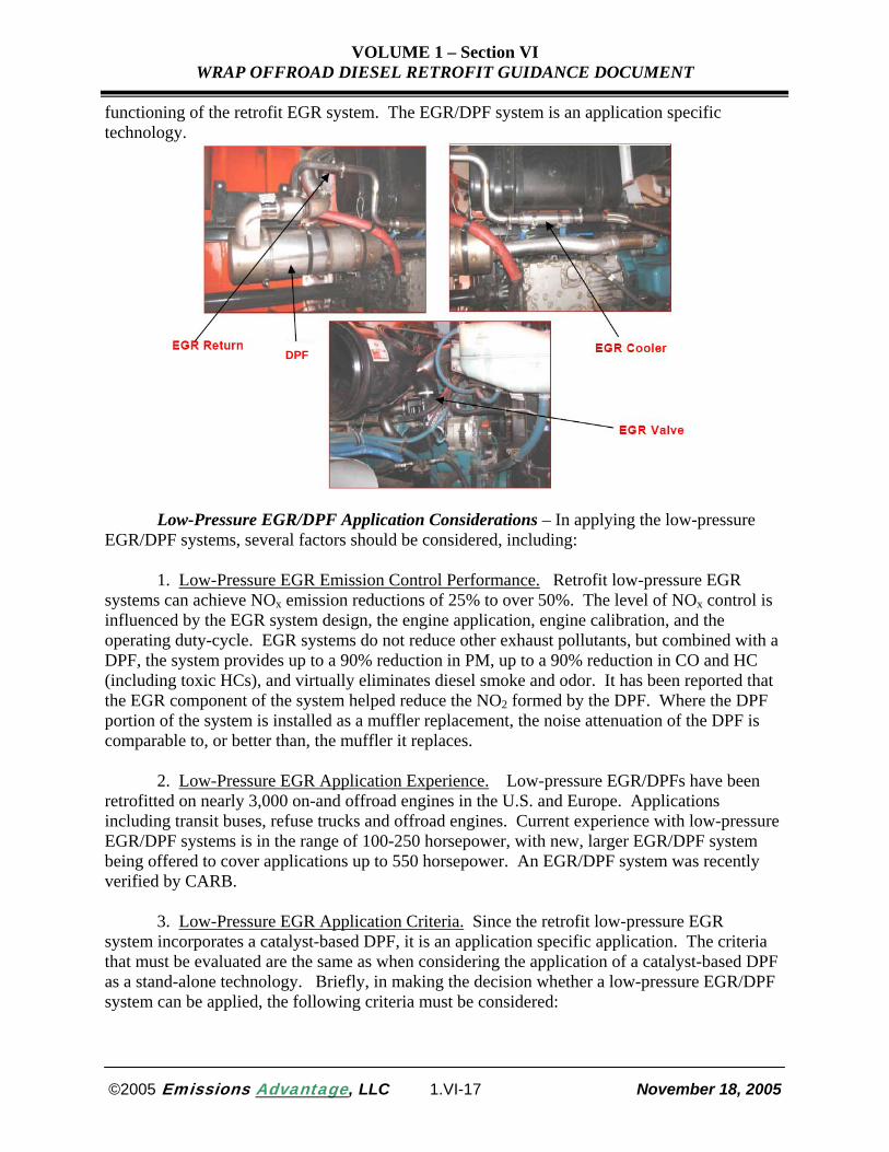
Low-Pressure EGR Technology Overview – EGR technology involves recirculating a
portion of an engine’s exhaust back into the turbocharger inlet, or the intake manifold of a naturally aspirated engine. In most EGR systems, an intercooler lowers the temperature of the recirculated exhaust. The recirculated exhaust, which has a higher heat capacity and contains less oxygen than the ambient air, lowers the combustion temperature of the engine, thereby reducing NOx formation. EGR systems can reduce NOx by up to 50% or more. In retrofit applications, a low-pressure EGR system has been combined with a catalyst-based DPF. The DPF collects PM from the exhaust, including exhaust that is recirculated. Preventing the PM in the exhaust from being reintroduced into the combustion process is critical to the proper
©2005 Emissions Advantage, LLC 1.VI-16 November 18, 2005
VOLUME 1 – Section VI WRAP OFFROAD DIESEL RETROFIT GUIDANCE DOCUMENT
functioning of the retrofit EGR system. The EGR/DPF system is an application specific technology.
DPF
Low-Pressure EGR/DPF Application Considerations – In applying the low-pressure
EGR/DPF systems, several factors should be considered, including: 1. Low-Pressure EGR Emission Control Performance. Retrofit low-pressure EGR
systems can achieve NOx emission reductions of 25% to over 50%. The level of NOx control is influenced by the EGR system design, the engine application, engine calibration, and the operating duty-cycle. EGR systems do not reduce other exhaust pollutants, but combined with a DPF, the system provides up to a 90% reduction in PM, up to a 90% reduction in CO and HC (including toxic HCs), and virtually eliminates diesel smoke and odor. It has been reported that the EGR component of the system helped reduce the NO2 formed by the DPF. Where the DPF portion of the system is installed as a muffler replacement, the noise attenuation of the DPF is comparable to, or better than, the muffler it replaces.
2. Low-Pressure EGR Application Experience. Low-pressure EGR/DPFs have been
retrofitted on nearly 3,000 on-and offroad engines in the U.S. and Europe. Applications including transit buses, refuse trucks and offroad engines. Current experience with low-pressure EGR/DPF systems is in the range of 100-250 horsepower, with new, larger EGR/DPF system being offered to cover applications up to 550 horsepower. An EGR/DPF system was recently verified by CARB.
3. Low-Pressure EGR Application Criteria. Since the retrofit low-pressure EGR
system incorporates a catalyst-based DPF, it is an application specific application. The criteria that must be evaluated are the same as when considering the application of a catalyst-based DPF as a stand-alone technology. Briefly, in making the decision whether a low-pressure EGR/DPF system can be applied, the following criteria must be considered:
©2005 Emissions Advantage, LLC 1.VI-17 November 18, 2005

VOLUME 1 – Section VI WRAP OFFROAD DIESEL RETROFIT GUIDANCE DOCUMENT
• The level of engine-out emission levels, including those from the engine lubricating oil. • The engine operating exhaust temperature profile.
• Available space to equip the low pressure EGR/DPF system.
• The level of sulfur in the diesel fuel.
4. Low-Pressure EGR Installation/Maintenance. Given the complexity of the low-
pressure EGR/DPF system, care should be taken in selecting and preparing the vehicle/equipment to be retrofitted and in installing, monitoring, and maintaining the system. The issues related to these factors are generally the same as when a DPF is retrofitted as a stand-alone technology. Installing the low-pressure EGR/DPF is performed by the technology provider and typically takes a two-person team up to eight hours to install the system.
5. Low-Pressure EGR Operating Experience, Issues and Solutions. A number of projects
involving low-pressure EGR/DPF systems are now underway in Europe and the U.S. with few, if any, problems reported. In some applications, as with any retrofit technology being first introduced, there were some start-up issues such as properly configuring the system on a given vehicle application. Also, as is the case with stand-alone DPF installations, some issues with premature filter plugging have occurred due in large measure to issues related to inadequate exhaust temperatures to ensure that the filter regenerates properly. This resulted in some unscheduled downtime to remove and clean the filter.
Information on the possible impact of low-pressure EGR/DPF technology on fuel
economy is very limited. One study reported a 1% to 4% fuel economy penalty, depending on the particular engine and test cycle used. The degree of fuel economy impact, if any, is likely influenced by such factors as level of NOx control efficiency, the engine, the application and the operating duty-cycle.
Closed Crankcase Ventilation (CCV) Emission Controls CCV Technology Overview – Diesel engines (as well as gasoline engines) leak some combustion gases past the engine piston rings. These gases are often referred to as “blow-by” and they pressurize the engine crankcase, which serves as the reservoir for the engine lubricating oil, picking up engine oil mist as they exit the crankcase vent. Blow-by gases that leave the crankcase also are referred to as “crankcase emissions” and they contain products of fuel combustion, partially combusted engine lubricating oil, and oil droplets. To control these emissions, some diesel engine manufacturers make CCV systems, which return the crankcase blow-by gases to the engine air intake for combustion. CCV systems prevent crankcase emissions from entering the atmosphere.
A retrofit CCV crankcase emission control system that controls crankcase emissions by
over 90% is commercial available in the U.S. for application on on-road and offroad engines. The costs of the verified CCV/DOC control ranges from about $1,100 to slightly over $2,000, depending on the engine application and the number of units sold under a given purchase order. The retrofit CCV system requires periodic replacement of the filter element (approximately $50).
©2005 Emissions Advantage, LLC 1.VI-18 November 18, 2005

VOLUME 1 – Section VI WRAP OFFROAD DIESEL RETROFIT GUIDANCE DOCUMENT
Other retrofit crankcase emission control systems are emerging, including a system that does not use a replaceable filter.
CCV Application Considerations – In applying CEC technology, several factors should
be considered, including: 1. CCV Emission Control Performance. Crankcase emissions from diesel engines
without CCV controls can be substantial, as much as 0.7 g/bhp-hr during idle conditions, even on relatively recent model year engines. Crankcase emissions include pollutants related to fuel combustion (e.g., PM), hydrocarbon aerosols, heavy HC materials and non-organic material from engine lubricating oil. Crankcase emissions range from 10% to 25% of the total engine emissions, depending on the engine and the operating duty cycle. Crankcase emissions typically contribute a higher percentage (up to 50%) of total engine emissions when the engine is idling. The retrofit CCV system, which is part of the DOC/CCV retrofit system being sold, virtually eliminates crankcase emissions (over 90%) during all engine operating modes. The CCV system consists of a filter housing, with a disposable filter that must be periodically replaced, a pressure regulator, a pressure release valve, and an oil check valve.
2. CCV/DOC Application Experience. A CCV emission control system combined with
a DOC has been introduced and verified for on-road applications by both the U.S EPA and CARB. The verified CCV/DOC retrofit system has been applied to both on-road (e.g., school buses) and offroad applications (e.g., marine port equipment). In the U.S. alone, over 2,000 diesel engines have been equipped with this system. 3. CCV/DOC Application Criteria. The application of the CCV/DOC system is quite broad. This technology has also been applied to a variety of offroad applications and a specially designed CCV crankcase emission control system can be applied to engines greater than 500 hp. Nevertheless, care should be taken to insure that the appropriate CCV technology matches the specific engine application. Installing the wrong CCV design can affect the filter efficiency/ durability and could affect engine performance.
4. CCV/DOC Installation/Maintenance. The retrofit CCV system is typically installed by the technology supplier. While the filter housing in some cases has been installed on the engine, to avoid problems with engine vibration or movement, it may be advisable to mount the housing on some other part of the vehicle such as the frame rail. The filter housing should also be mounted in a location that is easily accessible for servicing the filter. As noted above, DOC
©2005 Emissions Advantage, LLC 1.VI-19 November 18, 2005

VOLUME 1 – Section VI WRAP OFFROAD DIESEL RETROFIT GUIDANCE DOCUMENT
installation is relatively straightforward and can be performed by fleet technicians after they have received training.
Replacement of the disposable filter is very straightforward and can be performed as part
of the engine oil change servicing. Recommended filter replacement intervals vary based on the number of hours the vehicle/equipment is operated. As noted above, DOCs do not typically require maintenance, but periodic visual inspections are recommended; where PM emissions are very high, installing a backpressure monitor may be advisable.
5. CCV/DOC Operating Experience, Issues, and Solutions. Properly installed and
maintained CCV/DOC systems have performed effectively in on-road and offroad applications. Also, they do not adversely impact vehicle/equipment performance or fuel economy. If, however, the disposable filter is not replaced at the appropriate interval, the filter can clog. This can cause a pressure buildup in the crankcase and can lead to crankcase seal leakage and possible reduction in engine performance.
Engine Electronic Control Module (ECM) Reprogram
ECM Reprogram Overview – In October 1998, a court settlement was reached between
the EPA, Department of Justice, CARB and engine manufacturers (Caterpillar, Inc., Cummins Engine Company, Detroit Diesel Corporation, Volvo, Mack Trucks/Renault and Navistar/ International) over the issue of high NOx emissions from heavy-duty highway diesel engines during certain driving modes. Since the early 1990s, the manufacturers used software in the engine ECM that caused engines to switch to a more fuel-efficient (but higher NOx) driving mode during “off-cycle” steady highway cruising. These engines were built between 1993 and 1998 in a way that allowed the engines to pass EPA emission certification tests but increased emissions while the vehicle was being operated under conditions not included in the Federal Test Procedure (FTP) emission testing cycle used to establish compliance with EPA heavy-duty engine emission standards. It is estimated that 1.3 million engines contain the “off-cycle” ECM software.
The court settlement required the companies to introduce cleaner engines (including development of engines meeting the 2004 emission standards by October 2002, 15 months ahead of time), rebuild or reprogram older engines to cleaner levels, recall pickup trucks that have the so-called “defeat devices” and conduct new emissions testing. As part of the manufacturers’ requirements to rebuild or reprogram older engines (1993-1998) to cleaner levels, companies developed a heavy-duty diesel engine software upgrade (known as an ECM “reprogram”, “reflash” or “low NOx” software) that modifies the fuel control strategy in the engine’s ECM to reduce the excess NOx emissions
©2005 Emissions Advantage, LLC 1.VI-20 November 18, 2005

VOLUME 1 – Section VI WRAP OFFROAD DIESEL RETROFIT GUIDANCE DOCUMENT
ECM Reprogram Application Considerations – In considering an ECM reprogram, a
number of factors should be considered, including: 1. Offroad Engines with ECM. An ECM reprogram can be accomplished on only certain
on-road and offroad engines. Obviously, an ECM reprogram can be accomplished on only engines equipped with electronic engine controls. Many offroad engines are not electronically controlled, and cannot benefit from the ECM reprogram.
2. ECM Reprogram Emission Control Performance. On-road engines with low NOx
software are required to meet NOx emission standards based on the two options shown in Table VI-2, where Medium Heavy-Duty Diesel Engines (MHDDE) are used in vehicles with Gross Vehicle Weight Restrictions (GVWRs) of 14,001 to 33,000 pounds and Heavy Heavy-Duty Diesel Engines (HHDDE) are used in vehicles with GVWRs greater than 33,000 pounds.
Table VI-2, Low NOx Engine Software Certification Options
Option A Option B
Model Year/ Test Cycle
Application/ Emission Standard
Model Year/ Test Cycle
Application/ Emission Standard
1994-98 MHDDE HHDDE 1993-98 MHDDE HHDDE SET 6.0 g/bhp-hr 7.0 g/bhp-hr SET 6.5 g/bhp-hr 7.5 g/bhp-hr NTE 7.5 g/bhp-hr 8.75 g/bhp-hr NTE 8.1 g/bhp-hr 9.38 g/bhp-hr
Current Federal regulations do not require that complete heavy-duty diesel vehicles be emission-certified using a chassis dynamometer (as is used for light-duty vehicle emission testing), instead requiring that a manufacturer’s engines be certified using an engine dynamometer. Consequently, the basic emission standards are expressed in g/bhp-hr (grams per brake horsepower-hour) and require heavy-duty diesel engine emission testing over the Transient FTP engine dynamometer cycle. For comparison, the EPA FTP NOx emission standard for 1993-97 heavy duty diesel on-road truck engines was 5.0 g/bhp-hr and was 4.0 g/bhp-hr for 1998 heavy duty diesel truck engines. The NOx level for an older offroad diesel engine that was not required to meet any emission standards is typically over 10 g/bhp-hr.
Low NOx software was developed by the engine manufacturers to achieve compliance with existing on-road emission standards (for the specific year of manufacture). Thus, the software, in and of itself, as developed for satisfaction of the 1998 consent decree requirement does not constitute a means to reduce emissions below the on-road emission standards that were in place for the specific year of manufacture (in the classic sense of diesel emission reduction retrofit products). Catalytic exhaust aftertreatment retrofit products (typically a DOC or DPF) have been combined with (legally required) ECM reprograming for at least two engine manufacturers (International and Cummins) to create retrofit systems that reduce NOx, PM, HC and CO emissions below the emission standards that were in place for the year of engine manufacture. The system for Cummins 1994 through 1998 M11 engines has been verified by CARB as providing emissions reductions of 85% for PM and 25% for NOx. The International system is claimed to meet the U.S. EPA 2007 heavy-duty diesel engine emissions standards for PM and HC, and to be allowed by CARB as being qualified to share in California funding of new school bus purchases under the DRRP.
©2005 Emissions Advantage, LLC 1.VI-21 November 18, 2005

VOLUME 1 – Section VI WRAP OFFROAD DIESEL RETROFIT GUIDANCE DOCUMENT
3. ECM Reprogram Application Experience. To date, over 60,000 heavy-duty vehicles
have received ECM reprogramming. CARB has now required EMC reprogramming to be done on all applicable vehicles (estimated at between 300,000 to 400,000). The number of offroad engines receiving ECM reprogramming is not known. 4. ECM Reprogram Installation/Maintenance. ECM reprogram installations are available in California and throughout the U.S. at engine dealers and distributors. Low NOx software can be arranged to be installed at the local engine dealer/distributor or in instances where a large fleet operator is involved, the software can be installed on-site. The average ECM reprogram requires approximately 15 to 30 minutes for installation.
5. ECM Reprogram Issues and Solutions. One potential concern is for the engine’s ECM to fail after a low-NOx software install. Based on limited information provided to CARB, failure rate of the engine’s ECM is less than 1% as a result of the reprogram installation.
6. ECM Reprogram Impacts on Vehicle Performance. Manufactures have reported negligible impacts on fuel economy. Several fleets had the software installed prior to engine rebuilds and have reported no noticeable differences in their fuel use. CARB has recognized that there may be an average fuel economy penalty and expects it to be less than 1%. In addition, there have been no complaints regarding vehicle performance as a result of ECM reprogram installations.
Fuel-Based Strategies
Ultra-Low Sulfur Diesel (ULSD) Fuel
ULSD Product Overview – The EPA’s diesel fuel regulation limits the sulfur content in highway diesel fuel to 15 ppm (by weight), down from the previous 500 ppm. Refiners will be required to start producing the 15 ppm sulfur fuel beginning June 1, 2006. At the terminal level, highway diesel fuel sold as low sulfur diesel fuel must meet the 15 ppm sulfur standard as of July 15, 2006. For retail stations and wholesale purchasers, highway diesel fuel sold as low sulfur fuel must meet the 15 ppm sulfur standard by October 15, 2006 . Refiners can also take advantage of a temporary compliance option that will allow them to continue producing diesel fuel with up to 500 ppm sulfur content in 20% of the volume of diesel fuel they produce until December 31, 2009. In addition, refiners can participate in an averaging, banking and trading program with other refiners in their geographic area. ULSD will be required for use in offroad equipment beginning in 2010.
©2005 Emissions Advantage, LLC 1.VI-22 November 18, 2005

VOLUME 1 – Section VI WRAP OFFROAD DIESEL RETROFIT GUIDANCE DOCUMENT
ULSD Application Considerations – In considering ULSD, a number of factors should
be considered including:
1. ULSD Emissions Control Performance. Without the use of any other emission-reducing technology, the lower sulfur content of ULSD allows engine-out PM reductions of several percent (about 0.8% per 100 ppm reduction in sulfur content) compared to conventional highway low sulfur diesel fuel.
2. ULSD Application Experience. The U.S. Department of Energy, Energy Information
Administration (DOE-EIA) has estimated that in 2004, 137 million gallons of ULSD were produced (prior to EPA’s mandate) and made available in several areas of the country (primarily the West Coast, Mid-Atlantic, upper Mid-West, and the metro Houston areas) as a "technology enabler" to pave the way for advanced, sulfur-intolerant exhaust emission control technologies, such as DPFs and LNCs which will be needed to meet the 2007 emission standards.
3. ULSD Application Criteria. ULSD enables catalyst-based retrofit technologies such
as DPFs and DOCs to operate at maximum emission control efficiencies and effectiveness.
The lower sulfur content of ULSD has the benefit of reducing the acidic compounds that can promote fuel system corrosion, however, fuel-bound sulfur can help to promote fuel lubricity. The significant reduction of sulfur in ULSD, compared to conventional low sulfur diesel fuel can lead to increased wear in fuel injectors, particularly in older vehicles. Elastomer materials used in O-rings, seals and gaskets contained in fuel system components can also be degraded and fail. The diesel fuel industry is aware of this and is incorporating lubricity additives in ULSD to maintain lubricity.
4. ULSD Operating Experience. The significant majority of operators currently using ULSD have reported no problems with ULSD usage or delivery. Typical start-up problems involved failure of fuel pump seals on older model vehicles, plugged fuel filters, and leaking fuel system O-rings. Once the filters and O-rings were replaced, no further problems were experienced. Another problem identified was the need for periodic replacement of fuel dispensing equipment filters to achieve proper sediment and water control. This is a typical equipment maintenance practice and not considered unusual.
ASTM International has developed a fuel specification specific to ULSD. The Engine Manufacturers Association (EMA) recommends that anyone using ULSD do so with ULSD fuels meeting ASTM fuel specification D 975, and further, that the fuel have a minimum cetane number of 40, a minimum lubricity level of 3100 grams, and a minimum thermal stability value of 70% reflectance after aging for 180 minutes at a temperature of 150°C. Overall, the use of ULSD is expected to be transparent to vehicle users.
5. ULSD Issues and Solutions. To maintain the sulfur content integrity of ULSD,
pipelines and the equipment used for fuel transport and storage must be well maintained and kept free from contaminants. This includes excess sulfur residue that may have accumulated from prior handling of diesel fuels with higher sulfur content. Measures should also be taken to prevent vehicle misfueling with higher level sulfur content fuels and the resultant problems that can occur with sulfur-sensitive retrofit products such as DPFs. To minimize the chances of
©2005 Emissions Advantage, LLC 1.VI-23 November 18, 2005

VOLUME 1 – Section VI WRAP OFFROAD DIESEL RETROFIT GUIDANCE DOCUMENT
misfueling a vehicle with regular diesel fuel, signage warning of the need to refuel with ULSD can be developed and displayed in prominent places on vehicles and equipment refueling. Vehicle filler caps can also equipped with locks, the keys to which are available to only authorized personnel.
6. ULSD Impacts on Vehicle Performance. Most ULSD users have not reported any
impact on fuel economy when switching from regular low sulfur diesel fuel to ULSD. One user reported that test data taken at various intervals throughout the project indicated that the ULSD it used contained about 4% less energy content than regular low sulfur diesel fuel, but that the impact on fuel economy was minimal (approximately 0.15%). Another user operating line-haul delivery trucks reported a 3.54% fuel economy penalty attributable to the ULSD fuel it used. In both cases, the grade of fuel was not specified. Furthermore, rigorous and extensive data collection procedures and involved statistical analysis would need to be performed to be able to segregate the fuel economy effect of ULSD from that caused by other factors, including any other retrofit technology products.
It is important to note that the energy content of ULSD is not inherently lower than that of diesel fuel of higher sulfur content. The energy content of the most widely used diesel fuel grades (No. 1, No. 2, and No. 4) can vary by nearly 15% across all of the grades. The energy content can vary by up to 5% for No.2 diesel fuel, and by up to 2.5% for No. 1 diesel fuel. The energy content of No. 1 diesel fuel (which is often used as a blending component to winterize the No. 2 grade in areas with abnormally cold temperatures) is lower than that of No.2 diesel fuel, which is lower than that of No.4 diesel fuel (which is typically used in large diesel engines, particularly for marine applications).
The ASTM International specification for diesel fuels (currently D 975-04c) contains no specification for diesel fuel energy content. However, the National Conference on Weights and Measures (NCWM) and the EMA proposed definitions for so called “Premium Diesel” to ensure that consumers receive a functional benefit. In order to be sold as Premium Diesel fuel, the fuel must meet the minimum values for at least two of five criteria: 1) heating value (energy content), 2) cetane number, 3) low temperature operability, 4) thermal stability, 5) fuel injector cleanliness. Thus, those that purchase Premium Diesel (of any grade) may also not be assured of getting fuel with a minimum energy content.
In general, while the sulfur content of a fuel is not directly related to its energy content, some refinery processing methods used to remove sulfur from petroleum to the lower levels now required can alter the properties of the finished fuel in a way that results in a less dense fuel, for the same grade. Overall, as production of ULSD becomes widespread, the DOE-EIA estimates that an overall slight decline of 0.5% to 1.8% in energy content of ULSD might be possible.
Biodiesel
Biodiesel Product Overview – Biodiesel is a renewable distillate fuel derived from a number of vegetable oils, animal fats, or used frying oils. These oils are converted into methyl esters before they are used as diesel fuel. ASTM International defines biodiesel as the “mono alkyl esters of long chain fatty acids derived from renewable lipid feedstocks, such as vegetable oils and animal fats, for use in compression ignition engines.” In the 1980s and 1990s significant
©2005 Emissions Advantage, LLC 1.VI-24 November 18, 2005

VOLUME 1 – Section VI WRAP OFFROAD DIESEL RETROFIT GUIDANCE DOCUMENT
R&D was conducted to evaluate a variety of biodiesel blending stocks, develop emissions data, assess engine/vehicle performance, and develop cost-effective manufacturing processes. Pure biodiesel is referred to as B100, while biodiesel blends with petroleum-based diesel fuel are referred to as BXX, where “XX” is the volume percent of biodiesel fuel blended with the petroleum-based diesel fuel.
Some of biodiesel’s fuel properties, such as high cetane value or good lubricity, are obvious advantages of biodiesel while others, including the lower heating value, high freezing point (and inferior flow properties at low temperature), or corrosion properties are its drawbacks. Biodiesel changes the character and can increase the intensity of the odor of diesel exhaust.
In December 1998, the ASTM International Subcommittee D02.E0 approved the first provisional standard for the manufacture of biodiesel. Prior to that time, no common standard, or specification of characteristics important for reliable engine operation was available. The most recent specification for biodiesel was established in 2003 as “ASTM D6751-03a Standard Specification for Biodiesel Fuel (B100) Blend Stock for Distillate Fuels” and is to be used for blending with ASTM Specification D975 Grades 1-D, 2-D and low sulfur 1-D or 2-D diesel fuels. This current ASTM International specification includes test methods for establishing and measuring 35 individual biodiesel fuel characteristics or properties that are important to diesel engine/vehicle operation, including energy content, cetane number, cloud point, absorbed water, lubricity, viscosity, density, storage stability and flash point.
A specification for B20 is currently under development by ASTM International’s
Subcommittee D02.E0 as Work Item (WK) 6286. Specifications are under development for three grades of B20, with the biodiesel component of the blend conforming to the requirements of ASTM D6751, and the remainder of the fuel being a middle distillate grade diesel fuel conforming to ASTM D975:
• B20 (S15) with a diesel fuel component maximum sulfur level of 15 ppm. • B20 (S500) with a diesel fuel component maximum sulfur level of 500 ppm.
• B20 (S5000) with a diesel fuel component maximum sulfur level of 5000 ppm.
Biodiesel Application Considerations – In considering biodiesel, a number of factors should be considered including:
©2005 Emissions Advantage, LLC 1.VI-25 November 18, 2005

VOLUME 1 – Section VI WRAP OFFROAD DIESEL RETROFIT GUIDANCE DOCUMENT
1. Biodiesel Emissions Control Performance. Biodiesel fuel can reduce PM, HC, and
CO emissions, but typically increases NOx emissions (largely because of the chemically bound oxygen found in biodiesel). The percentage of emission reductions and increase in NOx is a function of the percentage of the fuel blend that is comprised of biodiesel.
Since the biodiesel base stock can come from a variety of sources (several different
vegetable oils, animal fats, waste cooking oils, etc.), the specific fuel properties vary somewhat, depending on the biodiesel source and degree of processing refinement. Thus, the specific emissions effects vary according to biodiesel fuel composition. Typical results are as follows: For total PM emissions, B20 provides about a 10-15 % reduction; for CO and HC (including the air toxics components of HC emissions), 0 to 10% reduction; for sulfate emissions (formed from SO2 emissions), up to 20% reduction; and for NOx, up to a 10% increase. PM2.5 reductions comprise about 3% or less, of the 10% reduction for total PM.
Compared to petroleum-based diesel fuel, biodiesel has been shown to reduce vapor-phase hydrocarbons in the C1 to C12 range, aldehydes and ketones, PAH and NPAH emissions, and has generated no new emission species compared to those currently present in diesel or biodiesel exhaust.
2. Biodiesel Application Experience. According to the National Biodiesel Board, current
and proposed biodiesel production plants are located in 20 states in the U.S. More than 1000 distributors are making biodiesel available in all 50 states. [See www.biodiesel.org]
Researchers from South Dakota State University and the University of Missouri-
Columbia undertook a survey of U.S. state transportation agencies to collect performance, storage and economic information related to the use of biodiesel fuels, and found that B20 was the most common biodiesel blend used across the country. This survey found five states that have mandated the use of biodiesel in state government vehicles, and that nearly 65% of the states in the U.S. reported either considering or enacting biodiesel blended fuel mandates, or using biodiesel blended fuel. In addition, there are a multitude of non-state DOT government agencies and private sector fleets that have either tested or are currently using biodiesel blends. B20 is an allowable fuel for satisfying the state government and fuel provider requirements for alternative fuel vehicle acquisition/usage under the Energy Policy Act of 1992 (EPACT).
3. Biodiesel Application Criteria. While there are no retrofit products that have been
verified for use with biodiesel fuels, available information from U.S. retrofit programs suggests that biodiesel blends do not appear to be incompatible with the use of DPFs and DOCs. Retrofit product manufacturers should be consulted before using any retrofit product with any biodiesel fuel.
Limited engine and vehicle testing suggest that compared to diesel fuel, the use of
biodiesel with DPFs, can extend the time to regeneration by up to four times. There is at least one DPF technology provider that is in the process of seeking verification with biodiesel fuels.
In general, no engine modifications need to be performed or special fuel additives be
incorporated when using biodiesel up to a blend level of B20 that has been produced to the latest ASTM International specifications. Aside for the lack of need for engine modifications,
©2005 Emissions Advantage, LLC 1.VI-26 November 18, 2005

VOLUME 1 – Section VI WRAP OFFROAD DIESEL RETROFIT GUIDANCE DOCUMENT
modifying an engine may potentially create a violation of EPA’s engine/vehicle anti-tampering provisions of the Clean Air Act. The Engine Manufacturers Association (EMA), Stanadyne Automotive (a major supplier of diesel engine fuel system components), and most diesel engine manufacturers (including General Motors, Ford Motor Company, Detroit Diesel Corporation, Deere and Company, Caterpillar, Inc., Cummins Engine Company, and International Engine Company) limit engine warranty coverage to use of biodiesel blends of 5% or less. Choice of a biodiesel blend level (particularly if the biodiesel component is greater than 20%) should be made with care, particularly if the engines using it are likely to be operating in subfreezing conditions that may contribute to fuel gelling of the biodiesel blending component.
4. Biodiesel Operating Experience. There are several U.S. projects that have
documented the use of biodiesel in diesel engine fleet applications as a retrofit strategy. The reasons most often cited are the effectiveness of emission reductions, ease of transition to use, and minimal impacts on current operating equipment and vehicles. According to the National Biodiesel Board, nearly 1.2 million gallons of biodiesel fuel were used in 2004, and as of January 2005, there were more than 400 major fleets using biodiesel, including all branches of the U.S. military, Yellowstone National Park, NASA, several state departments of transportation, major public utility fleets, various city agencies, and over 50 school districts. [See www.biodiesel.org]
5. Biodiesel Issues and Solutions. The diesel Fuel Injection Equipment (FIE)
manufacturers and EMA have developed positions on the use of biodiesel fuels in the products of their respective member manufacturers. In 2000, the U.S. Army developed a Department of Defense Purchase Description (DOD PD) for the use of B20 in diesel-powered non-tactical ground vehicles.
The FIE manufacturers have documented a number of operating problems with biodiesel fuels (particularly those used before the ASTM specifications were created). The key concern of these manufacturers is related to resistance to oxidation. Aged or poor quality biodiesel fuel may contain organic acids, free water, peroxides and products of fuel processing that may attack engine and fuel system components leading to reduced service life. The DOE National Renewable Energy Laboratory (NREL) has conducted a nationwide survey of biodiesel quality, and found several B100 specification failures (4 samples out of 27) for acid number, total glycerin or phosphorous. Further, of 50 samples of B20 taken nationwide, only 32 samples were actually found to contain about 20% biodiesel. Additives of the types used commercially in diesel fuel have been shown to provide improvements to the quality of biodiesel blends in areas such as detergency, water separation, cold flow characteristics, fuel system corrosion and foaming. Such additives should not be applied by fleet fuel users unfamiliar with fuels manufacturing and distribution. Given the variability in properties of biodiesel feedstocks, biodiesel should be purchased in accordance with the latest ASTM International specifications. Biodiesel fuels should be purchased from known, established suppliers that can attest to the quality of the biodiesel fuel product as being manufactured according to the latest ASTM International specification. The best place to have fuel quality verified (via testing) is as close to its final destination as possible, which is usually at the point of delivery to the user. Testing for conformance to key specifications at the point of delivery provides a minimal level of assurance that a quality
©2005 Emissions Advantage, LLC 1.VI-27 November 18, 2005

VOLUME 1 – Section VI WRAP OFFROAD DIESEL RETROFIT GUIDANCE DOCUMENT
product is being off-loaded into the user’s fuel storage equipment. Another means of assuring fuel quality is for buyers of biodiesel fuels to require that the supplier be BQ-9000 accredited by the National Biodiesel Accreditation Program (see www.bq-9000.org). This program is a unique combination of the ASTM International specification for biodiesel (ASTM D 6751) and a quality systems program that includes storage, sampling, testing, blending, shipping, distribution, and fuel management practices. The accreditation process is comprehensive and includes a detailed review of the supplier’s quality system documentation, followed by a formal audit of its system. As of the writing of this report, there were two BQ-9000 accredited suppliers in the U.S., with additional suppliers involved in the accreditation process.
Biodiesel, particularly at blend levels with diesel fuel of greater than B20, can be contaminated by growth of biological microorganisms. These microorganisms typically grow at the fuel-water interface and may not always be captured in fuel system filters. Should this occur, biocides are available to control growth. An excellent reference on this subject, Manual 47, Fuel and Fuel System Microbiology, is available from ASTM International, and provides a good understanding of fuel and fuel system biodeterioration, sampling requirements, test methods, and remediation practices.
6. Biodiesel Impacts on Vehicle Performance. Clean, well-maintained and monitored equipment (preferably dedicated to exclusive use of biodiesel fuels) should be used to store and dispense biodiesel fuels, to minimize the effects of water contamination, sediment pick-up, extended storage, temperature extremes and their subsequent problems. To minimize cold weather-related problems and gelling, biodiesel blends with diesel fuel should be stored in tanks that can ensure the fuel temperature will remain at least 5°F to 10°F above the cloud point of the blend.
The solvency action of biodiesel can loosen and carry fuel tank sediment that will collect
in fuel filters and clog them. Accordingly, fuel filters used on dispensers and engines should be inspected and replaced periodically. Such filters should be identified as being compatible for use with biodiesel fuels. Some fuel filter-related field problems with biodiesel blends were reported by a number of state DOT agencies. These filter problems declined or were completely resolved once the filters were replaced. Several state agencies avoided potential weather-related problems by discontinuing the use of biodiesel during cold weather periods.
Diesel Fuel Emulsions
Emulsions Product Overview – Diesel fuel emulsions are blended mixtures of diesel
fuel, water, emulsifying agents and other additives, that reduce PM and NOx emissions, as a result of the added water. Addition of water to the emulsified fuel also reduces the energy content of the fuel, with corresponding reductions in fuel economy and engine power.
©2005 Emissions Advantage, LLC 1.VI-28 November 18, 2005

VOLUME 1 – Section VI WRAP OFFROAD DIESEL RETROFIT GUIDANCE DOCUMENT
Emulsions Application Considerations – In considering diesel fuel emulsions a number
of factors should be considered including:
1. Emulsions Emissions Control Performance. Depending on the specific engine application and duty cycle, use of emulsions can result in NOx reductions of 5% to 30%, and PM reductions of 20% to 50%. These ranges of results have been demonstrated in several projects.
Use of an EPA-verified emulsified diesel fuel has been the subject of several studies, and for comparative purposes in several others. This emulsified diesel fuel is a combination of diesel fuel with 20% water by weight, and an "additive package" for stabilizing the fuel-water emulsion. In 2001, an eleven-engine database was developed to evaluate emissions from a baseline diesel fuel and the emulsified diesel fuel. Results showed that generally, the emulsified diesel fuel provided consistent reductions for NOx and PM. HC emissions were typically found to increase slightly. NOx reductions ranged from 3% to 30%, and for most of the test cases, PM reductions ranged between 24% and 83%.
2. Emulsion Application Experience. Currently, there is one technology provider of an EPA-verified emulsified fuel. The fuel product has been available from fuel suppliers on the West Coast, East Coast, Great Lakes area, and Gulf Coast. Emulsified fuels have been developed by other technology providers as well, but to date, have not been verified by EPA or CARB.
3. Emulsions Application Criteria. The University of Texas emulsified diesel fuel operational assessment identified a number of "user issues", including: higher cost, engine manufacturer's reluctance to extend engine warranties when alternative fuel formulations such as diesel fuel emulsions are used, the perception of detrimental effects on certain type engines, fuel-water separation concerns, and perceived health and safety issues. These observations were based on interviews with various users at different test and project locations in the northeast, southwest, and west coast. Other reports, including the Brunswick Mine Study provide an evaluation of similar worker and potential customer concerns.
Diesel fuel emulsions generally do not appear to be a good application for vehicles or
equipment that operate primarily at high speed and/or high load. Care should be given to assessing the operating characteristics of the candidate vehicles/equipment. Where the operating modes tend to be at lower loads and/or speeds fuel emulsions have been used successfully
4. Emulsions Operating Experience. Since this technology has been introduced into
commercial practice relatively recently, there is a lack of currently documented information on longer term user issues such as storage stability of mixed fuel, and the affects of ambient temperature on emulsion performance
5. Emulsions Issues and Solutions. Much of the same precautions and lessons learned
from use of ULSD and biodiesel can be applied to diesel fuel emulsions. Since emulsions contain water, there are potential use and storage problems related to their water content. Establishment of good fuel handing and storage practices and use of segregated equipment will help to minimize such problems.
©2005 Emissions Advantage, LLC 1.VI-29 November 18, 2005

VOLUME 1 – Section VI WRAP OFFROAD DIESEL RETROFIT GUIDANCE DOCUMENT
6. Emulsions Impacts on Vehicle Performance. Typically, reduced power and fuel
economy are related to the water content in the emulsified fuel, but engine operating mode (full power vs. low power) also affects the degree of reduction. These impacts in terms of costs, tradeoffs and the related benefits of achieving emission reductions with emulsified diesel fuels are a function of the properties of the specific emulsified fuel formulation, vehicles and equipment the emulsion will be used in, and duty cycles of operation.
Diesel Fuel Additives
Additives Product Overview – Fuel additives are chemicals added to fuel in very small amounts to improve one or more properties of the base fuel. Detergents, corrosion inhibitors and storage stability improvers are examples of commonly used fuel additives. More recently, additive manufacturers have developed products that improve the engine combustion process and reduce emissions, without compromising or negatively impacting the properties of the base fuel. Some emission-reducing fuel additives employ FBC materials that use catalytic processes to reduce emissions during engine combustion.
A variety of different materials have been employed as FBCs including copper, cerium,
cerium/platinum, iron/strontium, manganese and sodium. In the U.S. and Europe, the use of FBCs has been as part of a system with DPFs or DOCs. As noted, FBCs can also be used to facilitate regeneration of DPFs. As a general rule, the higher the level of FBC in the fuel, the more effective (i.e., the lower the exhaust temperature required to combust the soot) the catalyst’s performance. However, the higher the FBC level, the shorter the time interval before the DPF must be cleaned. One application required an FBC level of 30 ppm to 60 ppm for effective operation. Other applications require levels in the range of 8 ppm to 10 ppm. Cetane number improvers are a major class of diesel fuel additives that promote emission reductions (primarily NOx). In a recent report, EPA presented the results of an analysis of the impact of cetane improvers on NOx emissions. A statistical regression analysis found that if cetane improvers are added to a national average base fuel which would increase the cetane number by 5, NOx emissions would be lowered by a couple of percentage points.
Additives Application Considerations – In considering diesel fuel additives a number of
factors should be considered including:
©2005 Emissions Advantage, LLC 1.VI-30 November 18, 2005
VOLUME 1 – Section VI WRAP OFFROAD DIESEL RETROFIT GUIDANCE DOCUMENT
1. Additive Emissions Control Performance. FBCs have also been sold as stand-alone
products to be added to the fuel, even where exhaust aftertreatment emission control technology is not utilized. In one study, more than 94% of the additive was found to be retained in the engine and exhaust system. This retention level increased to 99% when a DPF was used. This study results also showed that at an ultra-low additive rate of 4 ppm to 8 ppm, ultra-fine PM did not increase. There are numerous manufacturers offering diesel fuel additives that are claimed to improve exhaust emissions, fuel economy, or both. In general, these improvements are claimed to be accomplished by improving combustion efficiency (by one means or another), resulting in reduced emissions. Additive manufacturers have developed proprietary formulations or fuel treatment processes, and license the process techniques/equipment and operating technology to small independent refiners that process the fuel into the finished product and sell it to users.
2. Additive Application Experience. Four retrofit projects in the U.S. since 2000
indicated that FBC additives were being used, at least one of which was in conjunction with a DPF. Approximately 1,600 delivery trucks operated by Coca-Cola have used an FBC additive.
3. Additives Application Criteria. In general, no engine modifications or changes to any other piece of fuel storage/dispensing or operating equipment are required to use these types of additives.
4. Additives Issues and Solutions. Progress is being made in developing precise on-
board dosing FBC systems. However, in retrofit applications, particularly where a DPF system is involved, the more prudent course to avoid potential problems with imprecise on-board FBC delivery may be to use premixed fuel (e.g., the FBC is added to the fuel storage tank or a dispensing pump is used that adds the appropriate amount of the FBC when vehicle fueling occurs).
Operations-Based Strategies Operations-based strategies such as idle reduction, engine rebuilding and early engine/vehicle replacement are very application specific and a function of a number of fleet operational issues. As such, these strategies are detailed individually, by offroad sector application, in Volume 2, Section XIV. STEPS FOR IMPLEMENTING THE TECHNICAL COMPONENTS OF A RETROFIT PROGRAM
Overview
Section II of this volume describes the overall retrofit program/project development process, and includes a Retrofit Program Decision Tree and Program Design/Implementation Checklist, which are designed to assist in planning, implementing, and evaluating retrofit programs. The sections below are designed to provide background discussion for those elements of the Decision Tree and Checklist relating to the technological elements of implementing a retrofit program. The elements discussed in this section include:
©2005 Emissions Advantage, LLC 1.VI-31 November 18, 2005

VOLUME 1 – Section VI WRAP OFFROAD DIESEL RETROFIT GUIDANCE DOCUMENT
• Selecting the retrofit strategy.
• Selecting the vehicle/equipment.
• Selecting the participating fleet(s).
• Fleet outreach, education, and training.
• Product procurement.
• Pre-installation requirements.
• Installation.
• Maintenance.
• Monitoring.
• Fuel considerations.
• Technical considerations in the termination of the project.
The discussion in this section is complemented by the information provided in Volume 2
for each of the available technology-, fuel- and operations-based retrofit strategies. Technology Selection
In selecting the appropriate retrofit technology, a number of factors should be considered
including:
• Is the technology consistent with the air quality goals of the program? • How complex is the technology?
• What is the performance track record of the technology?
• Are the personnel of the candidate fleet equipped to maintain and operate the technology?
• What are the costs of the technology?
• What are the available support services?
• Can the technology be effectively applied to the candidate vehicles/equipment being
considered?
©2005 Emissions Advantage, LLC 1.VI-32 November 18, 2005

VOLUME 1 – Section VI WRAP OFFROAD DIESEL RETROFIT GUIDANCE DOCUMENT
1. Goals of the Program – Technologies have different emission control performance
characteristics. Those performance characteristic should be matched to the air quality goals of the program. For example, if the goals are to achieve the maximum reductions in PM and toxic hydrocarbons, than a catalyst-based DPF which achieves over 90% reduction in PM mass, over 99% reduction in carbon-based PM, and up to a 90% reduction in ultra-fine particles might be the first choice. On the other hand if the goals are to maximize NOx reductions to the maximum degree possible, than SCR might be a leading candidate to consider.
2. Can the Technology be Applied – None of the technologies can be applied to every application, but some have broader applications than others. For example, DOCs and crankcase emission controls have near universal application, while other technologies like DPFs, LNCs, and low-pressure EGR systems have to be evaluated on a case-by-case basis.
3. How Complex is the Technology – The complexity of retrofit technologies varies. For example, DOC technology is very straight forward: 1) it has no moving parts, 2) it is relatively easy to install as a direct replacement (also has about the same dimensions as the muffler it replaces, 3) it typically does not require any maintenance, and 4) it does not impact vehicle performance or fuel economy. On the other hand, technologies like SCR are more complex, are often much larger than the existing muffler, and require a supply of reductant.
4. Track Record of the Technology – Overall, the track record of all EPA and CARB
verified technologies has been quite good. DOCs and crankcase emission controls have a near flawless record, DPFs have demonstrated excellent performance when they are properly applied (e.g., adequate exhaust temperatures to support regeneration of passive DPFs), maintained and fueled. NOx retrofit control strategies such as SCR, LNC and EGR are gaining experience and developing a good track record. It is important to keep in mind that when a technology is first being applied to a particular application or piece of equipment, start-up issues can arise.
5. Capability of Fleet Technicians and Operators – Technical capability, level of commitment, and time resources of fleet technicians and vehicle/equipment operators are important. Those fleets that have dedicated, well-trained technicians and operators are better candidates for employing the more complex technologies. Successful retrofits often have “champions”, those who take an active leadership role at the fleet management and/or maintenance levels to ensure the technical aspects of the program are being addressed.
6. Costs of Technologies – The cost of the technology is an important factor. The technology with the greatest emission reduction capability may not be the most cost-effective solution. A lower cost technology equipped on more vehicles may provide more emission reductions than a high efficiency high cost technology installed on a few vehicles.
7. Available Support Services – It is important to ensure that support services, particularly with the more complex technologies, will be available if needed. Generally, support services can be negotiated as part of the retrofit purchase agreement.
©2005 Emissions Advantage, LLC 1.VI-33 November 18, 2005

VOLUME 1 – Section VI WRAP OFFROAD DIESEL RETROFIT GUIDANCE DOCUMENT
Selecting the Appropriate Vehicles/Equipment
In selecting the appropriate vehicles for retrofit, three steps should be followed:
1. Collect/analyze information regarding the candidate vehicles/equipment and application.
2. Match the retrofit technology to the appropriate vehicles/equipment.
3. Ensure that engine warranty coverage in unaffected by the technology choice.
1. Collect and Analyze Vehicle/Equipment Information – To make informed decisions about applying retrofit technologies, a careful analysis of information relating the candidate vehicle/equipment should be made to eliminate inappropriate vehicles/equipment and to match vehicles/equipment with the appropriate retrofit strategies. A list of vehicle/equipment information needed is contained in Table 6-3.
Table 6-3, Equipment/Equipment Information
Engine Year & Type (mechanical or electronic)
Operating Characteristics (temperature ranges, load, fuel used, idling time and rugged use/safety issues)
Horsepower Rating Location of Operations (residential vs. industrial; rural vs. urban)
Emissions Certification Level Designated Year for Retirement
Exhaust System Type (single/dual)
Relevant Maintenance Histories of the Vehicles/Equipment (high oil consumption/frequent breakdowns)
Application or Duty Cycle (stop-and-go driving, short- or long-distance driving)
Ambient Temperatures Where Operated (e.g., extremely cold ambient temperatures)
2. Match the Retrofit Technology to the Appropriate Vehicles/Equipment – When
making the decision to apply a retrofit technology to a particular vehicle/equipment application, the following items should be considered:
• Engine size and backpressure specification.
• Engine duty cycle and resulting exhaust gas temperatures.
• Engine-out pollutants.
• Engine age.
• Fuel sulfur levels.
• Technology integration.
• Potential impacts on vehicle/equipment.
©2005 Emissions Advantage, LLC 1.VI-34 November 18, 2005

VOLUME 1 – Section VI WRAP OFFROAD DIESEL RETROFIT GUIDANCE DOCUMENT
a. Engine Size and Backpressure Specification – The engine size combined with its
backpressure specification will assist the technology manufacturer to properly size the retrofit control technology to insure that engine backpressure is not elevated above the engine manufacturer’s specifications.
b. Engine Duty-Cycle and Resultant Exhaust Gas Temperatures – Having the appropriate exhaust temperatures is a prerequisite to applying a number of technologies including passive DPFs, low pressure EGR/DPF systems, LNC systems, and SCR systems. Even DOCs, which will operate at lower temperatures, have minimum temperature requirements. Where information regarding exhaust temperatures is needed, data logging can be used. The operating cycle should be a representative worst-case cycle in terms of low load, low speed, and time at idle.
c. Engine-Out Pollutants – In some cases, the level of engine-out pollutants may be to
high to enable the retrofit technology to function. For example, older, high PM-emitting engines may not be good candidates for PM retrofits. For some retrofit technologies, the PM to NOx ratio must be at a certain level to sustain the use of the technology as is the case with certain catalyst-based DPF designs.
d. Engine Age – In many cases the engine in question may be nearing retirement and thus would not be a good candidate for retrofit.
e. Fuel Sulfur Levels – The sulfur level in the available fuel is a critical factor in deciding which retrofit technology to employ. For example with catalyst-based DPFs, diesel fuel with less than 15 ppm sulfur is recommended. Also, even if the level of sulfur does not preclude the use of a particular technology, it should be kept in mind that for all catalyst-based technologies, the higher the sulfur level the greater the impact on the effectiveness of the technology.
f. Technology Integration – The technology must be able to be integrated into the vehicle equipment in manner that permits the technology to operate effectively and does not interfere with vehicle/equipment operation or operator safety. A wide range of integration strategies are available including muffler replacement, in-line installation and other techniques.
g. Impact on Equipment/Equipment Operation – Some retrofit strategies, such as DOCs, have little or no impact vehicle/equipment operation, maintenance schedules, or fuel consumptions. Other technologies may impact vehicle operation (e.g., DPF with premature plugging requiring downtime to clean, or LNC which uses a small fraction of diesel fuel to serve as a reductant). The impacts of certain strategies may be acceptable given the emission reduction benefits but these trade-offs should be considered.
3. Insure that Engine Warranty is Unaffected by the Technology Choice – It is always advisable to check with the engine manufacturer to determine that use of a particular retrofit technology or product will not adversely affect the engine manufacturers’ warranty. The utilization of a particular retrofit technology on a particular engine application should not cause engine backpressure to exceed the engine manufacturer’s recommended limits.
©2005 Emissions Advantage, LLC 1.VI-35 November 18, 2005

VOLUME 1 – Section VI WRAP OFFROAD DIESEL RETROFIT GUIDANCE DOCUMENT
Selecting the Participating Fleet(s)
As is discussed in Section I of this volume, the factors to be considered in selecting fleets
and vehicles/equipment vary among offroad categories. However, several general factors exist that should be considered in selecting a fleet, including:
• Fleet vehicle/equipment inventory. • Publicly owned or funded fleets vs. private fleets.
• Vehicles/equipment owned, rented, or leased.
• Level of interest/support by fleet management. • Technical capability/support of fleet mechanics and operators.
1. Fleet Vehicle/Equipment Inventory – In considering a candidate fleet, an important
step is to gather information on fleet vehicles/equipment. This is important for two reasons: 1) to help determine which technology or technologies can be employed and 2) to help make the determination whether retrofitting fleet vehicles/equipment will serve the objectives of the project.
2. Publicly Owned or Funded Fleets v. Private Fleets – Experience has shown that it is often far easier to recruit publicly owned or funded fleets compared to recruiting fleets operated by private sector companies.
3. Vehicles/Equipment Owned, Rented or Leased – Typically, it is easier to implement a retrofit program if the vehicles/equipment is owned, as opposed to rented or leased. Those renting or leasing vehicles may be less interested in becoming involved in supporting a retrofit project because their equipment is move regularly from site to site. 4. Level of Interest/Support by Fleet Management – Having a strong and continued commitment by fleet management is absolutely critical to the ultimate success of a retrofit initiative.
5. Technical Capability/Support of Fleet Mechanics and Operators – The technical capability and the level of support by both the fleet technicians and operators must be sufficient to meet the needs of successfully applying and operating a given technology. In that regard, the level of technical capability and commitment needed is greater in those situations where a more complex technology, such as DPFs, which requires careful maintenance and monitoring than in cases where a DOC, which in most cases requires nether routine maintenance nor continuous monitoring.
Fleet Outreach, Education, and Training
During both the fleet recruiting stage and during the project planning and implementation phases, it is essential to maintain close, cooperative communications with the fleet management
©2005 Emissions Advantage, LLC 1.VI-36 November 18, 2005
VOLUME 1 – Section VI WRAP OFFROAD DIESEL RETROFIT GUIDANCE DOCUMENT
and other personnel as appropriate. Working with the fleets is discussed in more detail in Sections II and V of this volume. The training for fleet technicians and operators should match the level of the complexity of the retrofit technologies that will be employed.
Retrofit Product Procurement
An important step in implementing a successful retrofit program is establishing and
implementing a process for retrofit product acquisition. Major elements are discussed below, while more detailed discussion is contained in Section B of this section.
Retrofit Product Pre-Installation Requirements
Once the candidate vehicles/equipment and the type of technology has been selected, a
number of important actions are recommended prior to installing the retrofit device including:
• Performing necessary engine maintenance. • Ensuring the retrofit device is properly designed to fit the particular application.
• Scheduling product delivery to avoid delays and minimize downtime.
• Providing a secure storage facility for devices prior to installation.
• Confirming that all necessary installation hardware is included.
• Considering purchasing spare parts.
1. Perform Necessary Engine Maintenance. Proper maintenance including replacement
of worn and defective parts is an important step in ensuring a successful retrofit. Parts to check include leaky fuel injectors, the turbocharger, and the exhaust system (for leaks and secure fitting). Proper maintenance can also reduce fuel consumption and extend engine life.
2. Insure Retrofit Device Properly Designed for Application. Some retrofit products for some applications are stock fit, but in many, if not most instances, custom design and/or special piping and brackets may be needed. To ensure that the device delivered fits the application, the technology supplier should visibly inspect the vehicle/equipment and take necessary measurements or have access to information (drawing/photographs) that will enable it to properly configure the retrofit device. Conducting a “first fit” procedure, particularly where the retrofit technology is complex, is recommended. Under the first fit procedure, a retrofit device is installed on one vehicle/equipment to ensure that the device fits and to make any necessary modifications if it does not fit properly. Also, as part of this procedure, it is recommended to conduct a “shake-down” operation of the vehicle equipment for a short period (e.g. a week) to determine if any operational problems arise. Once the first fit process is successfully completed, installations on other vehicles/equipment may begin.
3. Schedule Product Delivery to Avoid Delays and Downtime. The delivery of retrofit products should be timed to minimize the downtime for the vehicles/equipment. For example, if
©2005 Emissions Advantage, LLC 1.VI-37 November 18, 2005
VOLUME 1 – Section VI WRAP OFFROAD DIESEL RETROFIT GUIDANCE DOCUMENT
there is going to be a period in which the vehicles/equipment will not be in service (e.g., between construction products or during routine maintenance), delivery should be planned accordingly. Since it not unusual for retrofit products to take longer to deliver than the vendor may have indicated, extra time should be factored into the delivery to account for delays that may occur.
4. Adequate Storage for Retrofit Devices. Often retrofit devices are delivered in bulk
even if the individual retrofit installations will be spread out over time. Indeed, there may be cost savings if products are bulk delivered. If a need exists to store devices pending installation, a secure, designate space for storage should be provided to guard against damage or theft.
5. Confirm All Necessary Installation Hardware is Included. Past experience indicates
that retrofit products when delivered may not always have all of the needed installation hardware (e.g., fasteners, brackets). Checking the deliveries to confirm all the necessary parts are included, can help prevent delays in product installation.
6. Consider Purchasing Spare Parts. To avoid unnecessary vehicle/equipment downtime,
and if funds are available, ordering spare parts may be advisable. Spare parts include additional retrofit devices (e.g. a DOC system), filters in the case of a DPF systems, additional installation hardware, and/or monitoring devices (e.g., backpressure monitor probes). The technology provider should be consulted in ordering the appropriate spare parts for a given project.
Retrofit Product Installation
Several considerations are critical in achieving a successful retrofit technology
installation, including:
• The time needed to complete the retrofit installations.
• The organization that will perform the installations.
1. How Long Will the Installation Take. The time needed to properly install a retrofit technology varies considerable. For example, installation of a muffler replacement DOC typically takes 1 to 2 hours, while the installation time for an SCR unit can take a full day or more. The time needed for any retrofit will vary somewhat depending on whether the unit being installed is a standard or custom fit and the ease of access in the engine compartment for installing the devices. Also, it is not unusual for more time to be needed in installing the first few devices. The key is to plan and account for unexpected delays in scheduling vehicles/equipment for retrofit product installation.
2. Who Will Perform the Installation. In the case of DPF, LNC/DPF, low-pressure
EGR/DPF, SCR and CCV systems, the installation is typically performed by the technology provider. With DOCs, installation is typically performed by fleet technicians. If fleet personnel are performing the installations, the technology provider should provide training and conduct post-installation inspections where appropriate.
©2005 Emissions Advantage, LLC 1.VI-38 November 18, 2005

VOLUME 1 – Section VI WRAP OFFROAD DIESEL RETROFIT GUIDANCE DOCUMENT
Equipment/Equipment and Retrofit Product Maintenance.
Regardless of the retrofit technology employed, the vehicle/equipment should be properly maintained. The maintenance required for different retrofit technologies will vary (See Individual Strategy Review and Application Considerations, above). For example, a DOC requires virtually no maintenance while other devices such as DPFs require regular scheduled cleaning. The technology provider should be consulted regarding the necessary maintenance and maintenance intervals for a particular product and application.
Monitoring Performance of the Retrofit Product Some retrofit technology includes monitoring equipment as part of the system. For example, DPFs come equipped with monitoring equipment that checks and records backpressure, and, in many cases, other data including exhaust temperatures. SCR systems have technology that monitors the level of reductant supply on-board. In those instances where such monitoring equipment is present, it should be checked at regular intervals to insure that it is working effectively. In addition, any retrofit technology should be visually inspected periodically to ensure that installation hardware is firmly in place, that there is no visible physical damage to the retrofit device (cracks, dents or leaks) that might affect performance, and that there are no leaks in the exhaust system. Fuel Considerations If special fuels are going to be used, such as ULSD, biodiesel blends, and/or diesel emulsions care must be taken to insure that 1) the fuel is properly blended, 2) it has the necessary lubricity additives if this is an issue, 3) special fuels are stored and dispensed in segregated facilities, 4) components like fuel pump filters and fuel injectors are compatible with the fuel used, and 5) the fuel is tested periodically at delivery and from samples taken from the vehicle/equipment to insure no contamination has occurred.
End-of-Project Technical Considerations
If the project has an end date, a decision will need to be made whether the technology should be removed or remain on the vehicle. For example if the retrofit technology requires the use of ULSD (e.g. catalyst-based DPF or LNC/DPF system) and the vehicle/equipment will no longer be fueled with the ULSD, the device should be removed (DPFs). Similarly, if the technology requires special maintenance such as filter cleaning or replacement of the reductant supply (SCR systems) and that maintenance can no longer be provided, again the retrofit system should removed. Technologies may be able to be reinstalled on other vehicles/equipment, but such use should be made in consultation with the technology provider. If the retrofit technology is scraped it should be disposed of in an environmentally responsible manner. Again, the technology provider should be consulted regarding any scrappage of retrofit technology devices. B. Approaches to Retrofit Product Acquisition
Effectively and efficiently carrying out retrofit product procurement is a critical step in helping to ensure a successful retrofit project. Failure to properly conduct product procurement
©2005 Emissions Advantage, LLC 1.VI-39 November 18, 2005

VOLUME 1 – Section VI WRAP OFFROAD DIESEL RETROFIT GUIDANCE DOCUMENT
can result in a number of problems including delays, added costs, fleet operation downtime, and issues with the funding source. The procurement process can be carried out if some basic guidelines are followed. This section sets out the steps that should be followed in purchasing retrofit products. PRE-PROCUREMENT REQUIREMENTS
The basic assumptions made in developing the content for this section were as follows:
• A retrofit program or project has been established. • Vehicle or equipment fleets have been identified as participants.
• Specific vehicles or equipment have been identified to be retrofitted.
• An organization has been identified to handle procurement matters.
• The rules and procurement procedures to be followed have been established.
• One or more specific retrofit technologies have been identified.
• Sufficient “homework” has been done to establish that there is at least one reputable
supplier of the retrofit products desired to be obtained. • A pre-bid meeting has been held for vendors to ask questions and inspect
equipment/vehicles to be retrofitted.
Retrofit product procurement should not be attempted until all of the above tasks have been completed.
PROCUREMENT REQUIREMENTS
Whether the procuring organization is a government entity or not, the process for specifying the desired retrofit products and the information needed to select a product supplier is the same. If the procuring organization is a Federal, state, or local government agency, each has a specified set of procurement procedures that are generally rooted in some form of regulation to be followed in purchasing any item or service. Among government agencies, purchasing requirements are typically very similar. It is not the intent of this document to describe those procedures, but rather to highlight elements of the process of procuring retrofit products that may not be addressed in those procedures.
To a large degree, the procedures to be followed for procuring retrofit products are likely to be a function of the source of funds used to purchase the products. In general, the “golden rule” applies, in that the supplier of funds determines the process and “rules” for the retrofit product procurement process. For example, any recipient of grant funds from a Federal agency to acquire retrofit products is typically required to follow the terms referenced in the grant agreement, which generally refer to a series of White House Office of Management and Budget
©2005 Emissions Advantage, LLC 1.VI-40 November 18, 2005

VOLUME 1 – Section VI WRAP OFFROAD DIESEL RETROFIT GUIDANCE DOCUMENT
(OMB) “Circulars”. These OMB Circulars contain information or instructions issued by OMB to Federal agencies, and the ones appropriate to the grant agreement are made a part of the agreement, usually by reference. Even though the language of the Circular itself may not be specifically spelled out in the grant agreement, the requirement to abide by its content still exists. Frequently cited OMB Circulars in Federal grant agreements are:
• Circular A-87, which describes the cost principles that state, local and Indian tribal
governments are to follow in structuring the costs of performing a grant project.
• Circular A-102, which describes the general provisions for awarding, administering and implementing grants with state and local governments.
• Circular A-110, which describes the administrative requirements for grants and other
agreements with institutions of higher education, hospitals and other nonprofit organizations.
• Circular A-122, which describes cost principles to be followed by non-profit
organizations.
• Circular A-133, which describes the requirements for auditing states, local governments and nonprofit organizations for the project and fiscal performance of Federal grants. Relative to procurement requirements, OMB Circulars A-102 and A-110 specify the
procedures to be followed and systems to be in place for assuring the rational and honest spending of Federal grant funds. The requirements specified in the Circulars are generally patterned after Federal procurement policies and procedures contained in the Federal Acquisition Regulations (FAR), and cover such topics as:
• Treatment of patent rights. • Development and submission of financial status reports.
• Resource conservation requirements.
• Contract closeout requirements.
• Standards for developing and determining fair and accurate pricing.
• Financial and project management requirements.
• Standards of care for use of Federal property or property bought with Government funds.
• Treatment of in-kind contributions and cost share.
• Financial disclosure requirements.
©2005 Emissions Advantage, LLC 1.VI-41 November 18, 2005

VOLUME 1 – Section VI WRAP OFFROAD DIESEL RETROFIT GUIDANCE DOCUMENT
• Code of conduct for procurement practices.
• Requirements and procedures for conducting competitive procurement.
• Requirements for contracting with small and minority firms, women’s business
enterprises and organizations in labor surplus areas. Any organization desiring to receive Federal grant funds should become familiar with the
requirements of the OMB Circulars listed above, as they cover all of the elements needed to carry out a procurement process in a way that will satisfy any post-grant auditing process that may be undertaken by or on behalf of the Federal Government (as outlined in OMB Circular A-133). BASIC PROCUREMENT NEEDS
Developing a complete definition and description of the retrofit profit products to be acquired is the most important part of the procurement process. This may appear to be obvious, but incomplete or inaccurate description of products to be acquired is often a factor in poor retrofit project outcome. An assessment of everything that is needed for the retrofit project and their methods of procurement should be performed before the procurement process is initiated. Items overlooked initially can cause unnecessary project delays to occur, and poor or incomplete specification of products can lead to installation difficulties that slow down project implementation. Examples of factors and items that need to be determined include:
• The requirement for any back-up suppliers for certain critical products and services (e.g., cleaning services for DPFs, ULSD for DPF applications).
• That the price of retrofit product installation performed outside of the participating fleet
includes ALL hardware needed for a complete installation, and that vehicles are returned in a “ready to run” condition.
• If any retrofit products to be installed in the exhaust system are to be of the muffler
replacement type or add-on type, which involve additional installation time, effort and complexity.
• ALL of the requirements for clamps, hangers, bolts, nuts, and any special installation
hardware.
• The requirements for any special tools, equipment or expendable items needed for retrofit product maintenance (e.g., cleaning equipment for DPFs).
• The requirement for any special signage, and other storage, dispensing or testing
equipment for effective application of fuel-based retrofit strategies.
• The requirement for and means to accomplish any pre-product-procurement technical functions such as data logging to determine if vehicle/equipment exhaust temperature
©2005 Emissions Advantage, LLC 1.VI-42 November 18, 2005

VOLUME 1 – Section VI WRAP OFFROAD DIESEL RETROFIT GUIDANCE DOCUMENT
profiles will be sufficient to support the use of DPFs, or engine mapping required for proper configuration and control system definition for SCR systems.
• The requirement for and means of obtaining the technical support functions necessary for
effective product evaluation (if needed), installation, operation, maintenance, and training of vehicle/equipment operating and maintenance personnel.
• The scope of the product warranty. • The required date for delivery of the product.
• The price of the retrofit product FOB to designated delivery site(s).
• The hardware cost and installation cost for any monitoring equipment that will be needed
(e.g. backpressure monitor/alarm for DPFs). PROCUREMENT METHODS
Vendor Selection
While it is possible to save some time in the procurement schedule by skipping the process of pre-qualifying vendors or product suppliers (as opposed to technology providers), vendor pre-qualification can often provide a valuable means of determining the best vendor candidates for a specific project. Not all product vendors have the same experience in providing products and technical support. Retrofit products are not quite at the level of being considered “commodity products” with little to no need for specialized technical support. As such, pre-selecting (before formal product solicitation requests are issued) those that can provide the best match of experience and capability will frequently pay dividends by reducing the time required for reviewing proposal responses and further qualifying one or more prospective vendors. An effective way to begin the vendor qualification process is by establishing a pre-procurement meeting with invited vendors. This is an excellent time for them to be given an overview of project needs, allow the vendors to ask questions, and provide them the opportunity to view vehicles to be retrofitted, and the operations and maintenance capabilities of the fleet(s) that are to receive retrofit products.
Piggy-Back With Other Agencies
State, local and Federal agencies have all used the concept of piggy-backing to accomplish the procurement of commodity products. State, regional, or even county purchase contracts covering multiple government agency fleets offer several advantages including: 1) an attractive price through volume purchasing, and 2) less administrative burden on individual procuring agencies by eliminating the need for going through the RFP process for selecting a retrofit product supplier and negotiating a contract. In the retrofit area, the Washington State School Bus Program is an example. Under this program, the State selects the technology provider and negotiates a purchase price. Retrofit products for the individual school districts in Washington can then be purchased from the State-selected provider at the negotiated price.
©2005 Emissions Advantage, LLC 1.VI-43 November 18, 2005

VOLUME 1 – Section VI WRAP OFFROAD DIESEL RETROFIT GUIDANCE DOCUMENT
Some states have considered piggy-backing on another state’s statewide purchasing
agreement with a product supplier in order to obtain a good price on retrofit products. The opportunity to piggy-back onto another agency’s procurement process (before or after it has been accomplished and a vendor has been selected) for retrofit products can provide potential cost savings, as long as the products to be acquired are exactly the same as those that are needed for the vehicle/equipment application(s). Care should also be taken to check the current price in the market against the price in the purchasing agreement. In some cases, the going market cost may actually be lower than the cost set in the purchase agreement.
Specification/Low Bid Approach vs Best Performance/Value Approach
The common practice (by most government agencies) of developing a product procurement specification requirement and issuing an RFP or Invitation For Bid (IFB) usually results in the award of a purchase to the product supplier with the lowest product price per vehicle. This practice generally works well for commodity products, but for the acquisition of retrofit products may lead to the selection of a product or supplier that does not provide the best overall value for the vehicle fleet. Table 6-4 illustrates an actual example comparing two retrofit project procurement approaches for two vehicle fleets for which approximately 400 vehicles were to be retrofitted with EPA-verified DOC products. One approach used the traditional specification/low bid selection process, while the other used a fleet-based “best performance/value” solicitation, with selection based on supplier responses to nearly 30 technical requirements.
Table 6-4, Comparison of Retrofit Product Procurement Approaches
REQUIREMENT ELEMENT SPECIFICATION/ LOW BID PROCESS
BEST PERFORMANCE/ VALUE SOLICITATION
Retrofit product warranty 1 Year 3 yrs/100,000 mi. to 5 yrs/150,000 mi.
Delivery and installation schedule 10 per week; 40-50 weeks to install
5 weeks for delivery of all; 12 weeks to install
PM reduction 20% 20% to 41% Retrofit product price per vehicle $840 $740 to $1,900
EMISSION REDUCTION AND COST EFFECTIVENESS COMPARISON PRODUCT SUPPLIER PRODUCT SUPPLIER A B C D Retrofit product price per vehicle $840 $1,555 $878 $840 Net program cost for 400 vehicle fleet $336,000 $302,000 $351,000 $336,000
Note several important points from Table 6-4: for the two fleets for which the comparison
was made, compared to the Specification/Low Bid approach, the Best Performance/Value Solicitation approach yielded supplier responses with:
• Product warranties that were significantly longer from all product suppliers. • Delivery and installation schedules that were significantly shorter.
©2005 Emissions Advantage, LLC 1.VI-44 November 18, 2005

VOLUME 1 – Section VI WRAP OFFROAD DIESEL RETROFIT GUIDANCE DOCUMENT
• Retrofit product price per-vehicle that was at least equivalent for one supplier.
• EPA-verified PM reduction levels that were equal to or greater.
• Net program costs that were lower and higher.
Note also from Table 6-4 that while the retrofit product from Supplier B was the highest price per vehicle, its overall cost to the fleet was the lowest.
©2005 Emissions Advantage, LLC 1.VI-45 November 18, 2005