
VG9000F rev 3 - Metso...Foundation fieldbus function blocks provide a general structure for...
52
Neles ValvGuard™ VG9000F Device revision 3 USER’S GUIDE (FOR FOUNDATION FIELDBUS FUNCTION BLOCKS) VG9000F en 11/2015
Transcript of VG9000F rev 3 - Metso...Foundation fieldbus function blocks provide a general structure for...

Neles ValvGuard™VG9000FDevice revision 3
USER’S GUIDE (FOR FOUNDATION FIELDBUS FUNCTION BLOCKS)
VG
9000F en 11/2015

2 NELES VALVGUARD™ VG9000F Device revision 3 USER’S GUIDE
Table of Contents1 Introduction .............................................................................................................................................32 VG9000F usage modes ............................................................................................................................3
2.1 VG9000F as Intelligent Solenoid Valve ...................................................................................................................... 32.2 VG9000F as On/Off Controller ...................................................................................................................................... 32.3 VG9000F as Hybrid Valve Controller ........................................................................................................................... 3
3 Device Setup ............................................................................................................................................43.1 Device Description installation .................................................................................................................................... 43.2 Basic setup steps................................................................................................................................................................ 4
4 Function Blocks ........................................................................................................................................64.1 Resource block ................................................................................................................................................................... 6
4.1.1 Overview .............................................................................................................................................................. 64.1.2 Parameters ........................................................................................................................................................... 64.1.3 Field diagnostics ..............................................................................................................................................12
4.2 Transducer block .............................................................................................................................................................144.2.1 Overview ............................................................................................................................................................144.2.2 Valve Calibration .............................................................................................................................................144.2.3 Partial Stroke Test ............................................................................................................................................154.2.4 Emergency Trip Test .......................................................................................................................................174.2.5 Pneumatics Test ...............................................................................................................................................184.2.6 Test error messages ........................................................................................................................................194.2.7 Trend graphs .....................................................................................................................................................204.2.8 Device statuses ...............................................................................................................................................214.2.9 Event log ............................................................................................................................................................244.2.10 Parameters .........................................................................................................................................................24
4.3 Multiple Discrete Input block (MDI) ..........................................................................................................................384.3.1 Overview ............................................................................................................................................................384.3.2 Parameters .........................................................................................................................................................39
4.4 Multiple Discrete Output block (MDO) ....................................................................................................................424.4.1 Overview ............................................................................................................................................................424.4.2 Parameters .........................................................................................................................................................43
4.5 Analog Input block .........................................................................................................................................................464.5.1 Overview ............................................................................................................................................................464.5.2 Parameters .........................................................................................................................................................46
5 LAS capability ........................................................................................................................................50

NELES VALVGUARD™ VG9000F Device revision 3 USER’S GUIDE 3
1. IntroductionNeles ValvGuardTM VG9000F is a microcontroller-based intelligent safety solenoid and partial stroke test device with Foundation fieldbus communication. It can be used in either emergency shutdown (ESD) or venting (ESV) valve applications.
VG9000F is applicable to SIS and applications that require testing of safety valves in order to maintain appro-priate safety integrity (SIL) level.
The main function of VG9000F is to work as an intelligent safety solenoid for ESD/ESV valves in safety applica-tion (usage mode safety is a default mode). In addition, it has additional usage modes; on/off and hybrid, for operating as a basic on/off controller or as a combined on/off valve controller and shutdown device together.
Foundation fieldbus function blocks provide a general structure for specifying different types of device func-tions. VG9000F has following function blocks:
• Resource block – Provides options that control the behaviour of all other blocks.• Transducer block – Provides interface for performing valve tests, calibration and valve configuration and
for reading valve diagnostics.• Multiple Discrete Output block – Provides interface for partial stroke test (PST) control via cyclic FF commu-
nication.• Multiple Discrete Input block - Provides discrete valve position, valve test and diagnostics status informa-
tion.• Analog Input block – Provides analog valve position information.
The detailed contents and usage of these Foundation fieldbus function blocks are described in this manual. The installation, maintenance and operating instructions (later known as IMO) (7VG9F70EN) shall be used together with this manual.
2. VG9000F usage modesThe main function of VG9000F is to work as an intelligent safety solenoid for ESD/ESV valves. Then the usage mode is Safety.
When the target is to work as an intelligent safety solenoid and also control the valve position (open/close) over the fieldbus with specified opening/closing times and profiles, if needed, then the desired usage mode is Hybrid.
The usage mode On/Off provides normal SOV functionality, open and close the valve. Valve opening and closing is controlled via 0/24 VDC signal interface.
2.1 VG9000F as Intelligent Solenoid ValveThe desired Usage mode is Safety.
Foundation fieldbus powers up the diagnostic part of the device and the emergency action is implemented by the safety system signal using 0/24 VDC wiring. All the diagnostics and testing are available in this mode.
2.2 VG9000F as On/Off ControllerThe desired Usage mode is On/Off. The 0/24 VDC signal is connected to the DCS and opens or closes the valve. Foundation fieldbus powers up the diagnostic part of the device.
When VG9000F is used as an on/off controller, all closing actions are considered as normal valve operation, not as safety actions. Partial stroke testing is not available in this mode.
2.3 VG9000F as Hybrid Valve ControllerThe desired Usage mode is Hybrid.
Foundation fieldbus powers up the diagnostic part of the device and the emergency action is implemented by the safety system signal using 0/24 VDC wiring.
The valve opening/closing can be controlled via DCS using Foundation fieldbus communication. Open and close commands override the testing. The safety action overrules everything and is the primary function of this mode.
4 NELES VALVGUARD™ VG9000F Device revision 3 USER’S GUIDE
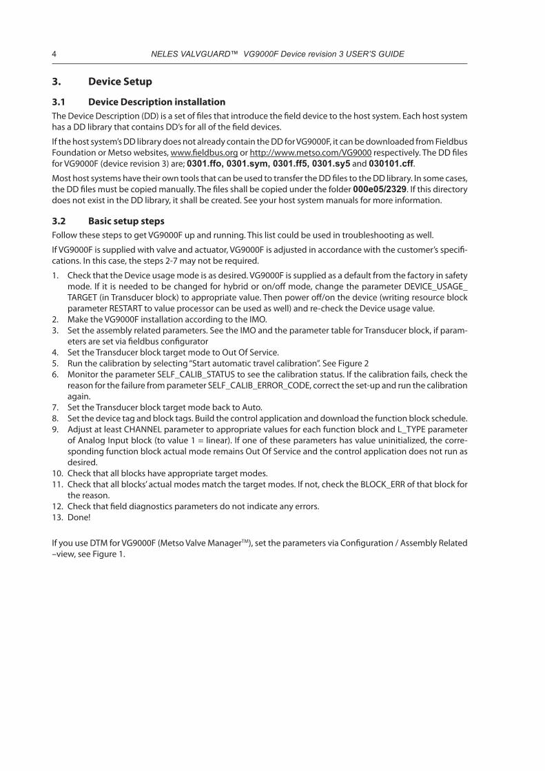
3. Device Setup
3.1 Device Description installationThe Device Description (DD) is a set of files that introduce the field device to the host system. Each host system has a DD library that contains DD’s for all of the field devices.
If the host system’s DD library does not already contain the DD for VG9000F, it can be downloaded from Fieldbus Foundation or Metso websites, www.fieldbus.org or http://www.metso.com/VG9000 respectively. The DD files for VG9000F (device revision 3) are; 0301.ffo, 0301.sym, 0301.ff5, 0301.sy5 and 030101.cff.Most host systems have their own tools that can be used to transfer the DD files to the DD library. In some cases, the DD files must be copied manually. The files shall be copied under the folder 000e05/2329. If this directory does not exist in the DD library, it shall be created. See your host system manuals for more information.
3.2 Basic setup stepsFollow these steps to get VG9000F up and running. This list could be used in troubleshooting as well.
If VG9000F is supplied with valve and actuator, VG9000F is adjusted in accordance with the customer’s specifi-cations. In this case, the steps 2-7 may not be required.
1. Check that the Device usage mode is as desired. VG9000F is supplied as a default from the factory in safety mode. If it is needed to be changed for hybrid or on/off mode, change the parameter DEVICE_USAGE_TARGET (in Transducer block) to appropriate value. Then power off/on the device (writing resource block parameter RESTART to value processor can be used as well) and re-check the Device usage value.
2. Make the VG9000F installation according to the IMO.3. Set the assembly related parameters. See the IMO and the parameter table for Transducer block, if param-
eters are set via fieldbus configurator4. Set the Transducer block target mode to Out Of Service.5. Run the calibration by selecting “Start automatic travel calibration”. See Figure 26. Monitor the parameter SELF_CALIB_STATUS to see the calibration status. If the calibration fails, check the
reason for the failure from parameter SELF_CALIB_ERROR_CODE, correct the set-up and run the calibration again.
7. Set the Transducer block target mode back to Auto.8. Set the device tag and block tags. Build the control application and download the function block schedule.9. Adjust at least CHANNEL parameter to appropriate values for each function block and L_TYPE parameter
of Analog Input block (to value 1 = linear). If one of these parameters has value uninitialized, the corre-sponding function block actual mode remains Out Of Service and the control application does not run as desired.
10. Check that all blocks have appropriate target modes.11. Check that all blocks’ actual modes match the target modes. If not, check the BLOCK_ERR of that block for
the reason.12. Check that field diagnostics parameters do not indicate any errors. 13. Done!
If you use DTM for VG9000F (Metso Valve ManagerTM), set the parameters via Configuration / Assembly Related –view, see Figure 1.

NELES VALVGUARD™ VG9000F Device revision 3 USER’S GUIDE 5
Figure 1. Assembly Related parameters’ setup in Metso Valve Manager (DTM)
Run the calibration by selecting “Start automatic travel calibration”. See Figure 2
Figure 2. Automatic Calibration in Metso Valve Manager (DTM)

6 NELES VALVGUARD™ VG9000F Device revision 3 USER’S GUIDE
4. Function BlocksStandard Function Blocks (FBs) are built into fieldbus devices as needed to achieve the desired functionality. There can be many types of FBs in a device. The order and definition of function block parameters are fixed and defined by the specifications.
4.1 Resource block
4.1.1 OverviewThe Resource block provides options that control the behaviour of all other blocks. The block contains also device revision information and firmware and hardware version information.
4.1.2 ParametersResource block parameters are presented in Table 1
Table 1. Resource block parameters.
Resource block parameter name DescriptionST_REV The revision level of the static data associated with the function block. The
revision value will be incremented each time a static parameter value in this block is changed.Default: 0
TAG_DESC The user description of the intended application of the block.Default:” “
STRATEGY The strategy field can be used to identify grouping of blocks. This data is not checked or processed by the block.Default: 0
ALERT_KEY The identification number of the plant unit. This information may be used in the host for sorting alarms, etc.Default: 0
MODE_BLK MODE_BLK contains the actual, target, permitted, and normal modes of the block.
• ACTUAL is the current mode of the block, which may differ from the target based on operating conditions. Its value is calculated as part of block execution.
• TARGET is the mode requested by the operator. Only one mode from those allowed by the permitted mode parameter may be requested.
• PERMITTED defines the modes which are allowed for an instance of the block. The permitted mode is configured based on application require-ment.
• NORMAL is the mode which the block should be set to during normal operating conditions.
Resource block modes are: • Out of Service (O/S) - O/S mode stops all function block execution. The
actual mode of the function blocks in this resource will be changed to O/S, but the target mode will not be changed.
• Initialization Manual (IMan) - IMan shows that the resource is initializing or receiving a software download.
• Automatic (Auto) - Auto mode allows normal operation of the resource.Default: target O/S

NELES VALVGUARD™ VG9000F Device revision 3 USER’S GUIDE 7
Resource block parameter name DescriptionBLOCK_ERR This parameter reflects the error status associated with the hardware or soft-
ware components associated with a block. It is a bit string, so that multiple errors may be shown.
• Other; Non-specific error active.• BlockConfiguration; Error detected in block configuration.• LinkConfiguration; Error detected in link configuration.• SimulationActive; Simulation enabled in this block. For the resource
block, Simulate Active will be used to indicate that the simulate hardware jumper is present. An active state (1) of this attribute will indicate that the jumper is present and that it is possible for the user to enable simulation in the AI function block. For AI block this indicates either the simulation is enabled or disabled.
• LocalOverride; Output tracking or faultstate active.• DeviceFaultstate; Device faultstate set.• Device needs maintenance soon• InputFailure; Process variable has bad status.• OutputFailure; Failure detected in output hardware.• MemoryFailure; Memory error detected.• LostStaticData; Static parameters cannot be recovered.• LostNVData; Non-Volatile parameters cannot be recovered.• ReadbackCheck; Failure detected in READBACK.• Device needs maintenance now• PowerUp; Recovery from power failure.• OutOfService; Block actual mode is Out of Service.
Default: 0
RS_STATE The overall state of the function block application state machine.• Undefined - Invalid state.• Start/Restart - This state will be entered after detection that power has
been restored to a device. In this state, the memory and other hardware necessary for reliable operation will be tested. An important part of the recovery process is being able to restore static data, which includes both the “static” and “non-volatile” types of parameters. The validity of static memory will be tested. If the object’s static data is bad, then the object’s database will be set to its default values. A block should be issued, with the subcode set to either “Lost static data” or “Lost NV data” as appro-priate. After successfully initializing, the associated resource block should generate a block alarm with the subcode set to “Power-up”. If the hard-ware tests are successful, the resource state will change to the initializa-tion state. Otherwise, resource state will change to the Failure state.
• Initialization - The initialization state is entered from the Start/Restart or Failure states. In the Initialization state, all unreported function block alarms will be automatically confirmed and acknowledged. Once the system is detected to be Operational, block execution may be scheduled and the resource state will change to On-Line Linking.
• On-line Linking - This state will be entered from the On-Line and Initiali-zation state. In this state, the status of defined links will be evaluated. If all defined links are established, then the resource state will change to On-Line.
• On-line - The On-Line state will be entered from the On-Line Linking state. In this state, the status of defined links will be evaluated. If one or more defined links are detected as not established, then the resource state will change to On-Line Linking
• Standby - This state will be entered if the mode of the resource block is changed to Out-of-Service (O/S). In this state the actual mode of all func-tion blocks in the resource will be forced to O/S mode. The mode of trans-ducer blocks may not be affected. This state will be maintained until the mode is changed to Auto. On a change in the resource block mode to Auto, the state will change to Start/Restart.
• Failure - This state may be entered from any state except Standby. Transi-tion to this state is caused by the detection of a memory or other hardware failure, which would prevent reliable operation. The failure may pertain either to the whole device or only to the resource. Based on this state being active, a function block of the output class may change its output to a Fault State position. In this state, hardware status will be tested. If the hardware failure clears, then the state will change to Initialization.
Default: 0

8 NELES VALVGUARD™ VG9000F Device revision 3 USER’S GUIDE
Resource block parameter name DescriptionTEST_RW Read/write test parameter - used only for conformance testing.
Default: 0
DD_RESOURCE String identifying the tag of the resource which contains the Device Descrip-tion for this device.Default: “ “
MANUFAC_ID Manufacturer identification number - used by an interface device to locate the DD file for the resource.Value: 000E05
DEV_TYPE Manufacturer’s model number associated with the resource -used by interface devices to locate the DD file for the resource.Value: 2329
DEV_REV Manufacturer revision number associated with the resource - used by an inter-face device to locate the DD file for the resource.Value: 3
DD_REV Revision of the DD associated with the resource - used by an interface device to locate the DD file for the resource.Value: 1
GRANT_DENY The grant-deny parameter is used to allow the operator to grant and deny access permission to sets of function block parameters by other devices. The parameter has two attributes named Grant and Deny. The operation of these parameters is defined here, but the actual usage (if any) depends on the philosophy of the plant.Grant - Depending on the philosophy of the plant, the operator or a higher level device (HLD), or a local operator’s panel (LOP) in the case of Local, may turn on an item of the Grant attribute - Program, Tuning, Alarm, or Local. By doing or allowing this action, the operator gives up control of the selected parameters to the HLD or LOP. The function block does not check writes to any of the selected parameters for grant-deny permission. It is up to other devices to obey and enforce the rules, because the function block has no way to know who is writing to it. When the operator wants to regain control of the param-eters, he clears the Grant item. The function block will then automatically set the corresponding Denied item. This indicates to the HLD or LOP that control has been taken away.
• Program - A higher level device may change the target mode, setpoint (if the block mode is Man or Auto), or output(if the block mode is Man) of the block.
• Tune - A higher level device may change the tuning parameters of the block.
• Alarm - A higher level device may change the alarm parameters of the block.
• Local -A local operator’s panel or hand-held device may change the target mode, setpoint (if the block mode is Man or Auto), or output (if the block mode is Man) of the block.
Deny - The Denied attribute is provided for use by a monitoring application in an interface device and may not be changed by an operator. It allows the moni-toring application to determine if control has been temporarily taken away during the execution of a batch program. This is done by first clearing one or all of the Denied items before execution of a batch program, then checking the Denied item after execution. The Grant item itself should not be checked for this condition, because the operator may have cleared and subsequently set the Grant item during batch program execution, a sequence that might be missed by a slowly scanning monitor program. The Denied item may not be cleared by the operator, thus latching the fact that control was taken away.
• Program - The Program permission item has been turned off.• Tune Denied - The Tune permission item has been turned off.• Alarm Denied - The Alarm permission item has been turned off.• Local Denied - The Local permission item has been turned off.
Default: 0;0
HARD_TYPES The types of hardware available as channel numbers.Value: 0x000EScalar input | Scalar output | Discrete input | Discrete output

NELES VALVGUARD™ VG9000F Device revision 3 USER’S GUIDE 9
Resource block parameter name DescriptionRESTART Allows a manual restart to be initiated. Several degrees of restart are possible:
• Run - This is the passive state of the parameter.• Restart resource - Not in use.• Restart with defaults - This restarts the device with defaults.• Restart processor - This restarts the processor.
Default: 1
FEATURES Used to shows supported resource block options.Value: 0000010000010110 (2 bytes bit string)1046 (dec. value), 0x0416 (hex. value)Reports | Fault state | Hard write lock | Multi-bit alarm support‘Multi-bit alarm support’ allows multiple errors being shown in the same alarm.
FEATURE_SEL Used to select resource block options.• Reports - If set, the device supports alert reports. If it is not set, the master
must poll for alerts.• Faultstate - If set, setting the SET_FSTATE parameter will force all output
function blocks in the resource to go to fault state. • Hard W Lock - This enables the use of the hardware write lock switch. See
WRITE_LOCK.Value: 0000010000010110 (2 bytes bit string)1046 (dec. value), 0x0416 (hex. value)Default: 0x416Reports | Fault state | Hard write lock | Multi-bit alarm support‘Multi-bit alarm support’ allows multiple errors being shown in the same alarm.
CYCLE_TYPE Identifies the block execution methods available for this resource.Value: 3Scheduled/block execution
CYCLE_SEL Used to select the block execution method for this resource.Default: 3Scheduled/block execution
MIN_CYCLE_T Time duration of the shortest cycle interval of which the resource is capable.Value: 960 (1/32 ms)
MEMORY_SIZE Available configuration memory in the empty resource. To be checked before attempting a download.Value: 0 (not supported)
NV_CYCLE_T Minimum time interval specified by the manufacturer for writing copies of NV parameters to non-volatile memory. NV memory is updated only if there has been a significant change in the dynamic value. The last value saved in NV memory will be available after restart. Zero means that NV data will only be copied to NV memory when an external write request is received.Value: 0
FREE_SPACE Percent of memory available for further configuration. Zero in a preconfigured device.Value: 0
FREE_TIME Percent of the block processing time that is free to process additional blocks.Value: 0
SHED_RCAS,SHED_ROUT
SHED_RCAS and SHED_ROUT set the time limit for loss of communication from a remote device. These constants are used by all function blocks that support a remote cascade mode. Shedding from RCAS/ROUT shall not happen when SHED_RCAS or SHED_ROUT is set to zero.Default: 640000
FAULT_STATE Condition set by loss of communication to an output block, failure promoted to an output block or a physical contact. When fault state condition is set, then output function blocks will perform their FSTATE actions.Default: 1
SET_FSTATE Allows the fault state condition to be manually initiated by selecting Set. See FEATURE_SELDefault: 1
CLR_FSTATE Writing a Clear to this parameter will clear the device fault state if the field condition, if any, has cleared.Default: 1

10 NELES VALVGUARD™ VG9000F Device revision 3 USER’S GUIDE
Resource block parameter name DescriptionMAX_NOTIFY Maximum possible number of unconfirmed alert notify messages.
Default: 15
LIM_NOTIFY Maximum number of unconfirmed alert notify messages allowed.Default: 15
CONFIRM_TIME The minimum time between retries of alert reports.Default: 640000
WRITE_LOCK Shows the state of the hardware switch. If set, no writes from anywhere are allowed. Block inputs will continue to be updated.Default: 1 (Not locked)
UPDATE_EVT An alert for any change in the static data, UDATE_EVT, is included in each block. This alert can notify interface devices that keep track of changes that one or more changes have occurred. The relative parameter index and its asso-ciated block index is included in the alert, along with the new value of ST_REV. If more than one change was added since the last reported Update Alert, as known from the difference between the last copy of ST_REV and the one in the alert, it will be necessary for the interface device to update all static data. No alert will be generated while a block is in Out of Service mode, so that down-loads will not generate many update alerts.ST_REV will be incremented for each change to static data that occurs while the block is in the O/S mode. On the transition out of O/S mode, an update alert may be generated if the value of ST_REV for the block does not match that of the last reported alert. Update Alert has a fixed priority of 2, therefore it is autoacknowledged (no operator intervention is required).
• Unacknowledged - A discrete enumeration which is set to Unacknowl-edged when an update occurs, and set to Acknowledged by a write from a human interface device or other entity which can acknowledge that the alarm has been noticed.
• Update State - A discrete enumeration which gives an indication of whether the alert has been reported.
• Time Stamp - The time when evaluation of the block was started and a change in alarm/event state was detected that is unreported. The time stamp value will be maintained constant until alert confirmation has been received - even if another change of state occurs.
• Static Rev - the static revision of the block whose static parameter was changed and is being reported. It is possible for the present value of static revision to be greater than this because static can be changed at any time.
Relative Index - The OD index of the static parameter whose change caused this alert, minus the FB starting index. If the update event was caused by a write to multiple parameters at the same time, then this attribute will be zero.Default: 0;0;0,0;0
BLOCK_ALM The block alarm is used for all configuration, hardware, connection failure or system problems in the block. The cause of the alert is entered in the subcode field. The first alert to become active will set the Active status in the Status attribute. As soon as the Unreported status is cleared by the alert reporting task, another block alert may be reported without clearing the Active status, if the subcode has changed.
• Unacknowledged - A discrete enumeration which is set to Unacknowl-edged when an update occurs, and set to Acknowledged by a write from a human interface device or other entity which can acknowledge that the alarm has been noticed.
• Update State - A discrete enumeration which gives an indication of whether the alert has been reported.
• Time Stamp - The time when evaluation of the block was started and a change in alarm/event state was detected that is unreported. The time stamp value will be maintained constant until alert confirmation has been received even if another change of state occurs.
• Subcode - An enumeration specifying the cause of the alert to be reported. Enumerations are equal with the BLOCK_ERR.
• Value - The value of the associated parameter at the time the alert was detected.
Default: 0;0;0,0;0

NELES VALVGUARD™ VG9000F Device revision 3 USER’S GUIDE 11
Resource block parameter name DescriptionALARM_SUM The current alert status, unacknowledged states, unreported states, and disa-
bled states of the alarms associated with the function block.• Current - The active status of each alarm.• Unacknowledged - The unacknowledged state of each alarm.• Unreported - The unreported status of each alarm.• Disabled - The disabled state of each alarm.
Default: 0;0;0;0
ACK_OPTION Selection of whether alarms associated with the function block will be auto-matically acknowledged.Default: 0
WRITE_PRI Priority of the alarm generated by clearing the write lock.• 0 = the associated alert may clear when the priority is changed to 0, but
it will never occur.• 1 = the associated alert is not sent as a notification. If the priority is above
1, then the alert must be reported.• 2 = reserved for alerts that do not require the attention of a plant operator,
e.g. diagnostic and system alerts. Block alarm, error alarm, and update event have a fixed priority of 2.
• 3-7 = increasing higher priorities - advisory alarms.• 8-15 = increasing higher priority - critical alarms.
Default: 0
WRITE_ALM This alert is generated if the write lock parameter is cleared.• Unacknowledged - A discrete enumeration which is set to Unacknowl-
edged when an update occurs, and set to Acknowledged by a write from a human interface device or other entity which can acknowledge that the alarm has been noticed.
• Alarm State - A discrete enumeration which gives an indication of whether the alert has been reported.
• Time Stamp - The time when evaluation of the block was started and a change in alarm/event state was detected that is unreported. The time stamp value will be maintained constant until alert confirmation has been received - even if another change of state occurs.
• Subcode - An enumeration specifying the cause of the alert to be reported. Enumerations are equal with the BLOCK_ERR.
• Discrete Value - The value of the associated parameter at the time the alert was detected
Default: 0;0;0,0;0;0;0;10;0;0
ITK_VER Major revision number of the interoperability test system used in certifying this device as interoperable.ITK version used in the certification of VG9000F is version 6.
DEVICE_SER_NUM Device machine plate serial number.Value: 16 chars
FBI_SOFTWARE_REVISION Fieldbus interface board software revision number.Value: F18289-3.X
FBI_HARDWARE_REVISION Fieldbus interface board hardware revision number.Value: H130105-X.X
FBI_BOARD_SN Fieldbus interface board serial number.Value: 16 chars
VC_SOFTWARE_REVISION Valve controller board software revision number.Value: F18288-X.X
VC_HARDWARE_REVISION Valve controller board hardware revision number.Value: 16 chars
VC_BOARD_SN Valve controller board serial number.Value: 16 chars
DEVICE_TEST_STATUS This parameter is only for Metso internal use.Default: 0
IDENTIFICATION_DATA_TAG1 … 12 These parameters are only for Metso internal use.Default: “ “
FD_VER Version of Field Diagnostics specification used in the implementation of this device is 1

12 NELES VALVGUARD™ VG9000F Device revision 3 USER’S GUIDE
Resource block parameter name DescriptionFD_FAIL_ACTIVE Bit string parameter reflecting active error conditions for ‘Failed’ category
FD_OFFSPEC_ACTIVE Bit string parameter reflecting active error conditions for ‘Off specification’ category
FD_MAINT_ACTIVE Bit string parameter reflecting active error conditions for ‘Maintenance’ cate-gory
FD_CHECK_ACTIVE Bit string parameter reflecting active error conditions for ‘Check function’ cate-gory
FD_FAIL_MAP Selection of error conditions to be detected as active for ‘Failed’ category
FD_OFFSPEC_MAP Selection of error conditions to be detected as active for ‘Off specification’ category
FD_MAINT_MAP Selection of error conditions to be detected as active for ‘Maintenance’ cate-gory
FD_CHECK_MAP Selection of error conditions to be detected as active for ‘Check function’ cate-gory
FD_FAIL_MASK Selection of error conditions to be suppressed from broadcasting as alarms in ‘Failed’ category
FD_OFFSPEC_MASK Selection of error conditions to be suppressed from broadcasting as alarms in ‘Off specification’ category
FD_MAINT_MASK Selection of error conditions to be suppressed from broadcasting as alarms in ‘Maintenance’ category
FD_CHECK_MASK Selection of error conditions to be suppressed from broadcasting as alarms in ‘Check function’ category
FD_FAIL_ALM Alarm parameter which is used to broadcast a change in the associated active condition in ‘Failed’ category
FD_OFFSPEC_ALM Alarm parameter which is used to broadcast a change in the associated active condition in ‘Off specification’ category
FD_MAINT_ALM Alarm parameter which is used to broadcast a change in the associated active condition in ‘Maintenance’ category
FD_CHECK_ALM Alarm parameter which is used to broadcast a change in the associated active condition in ‘Check function’ category
FD_FAIL_PRI Priority of alarm in ‘Failed’ category
FD_OFFSPEC_PRI Priority of alarm in ‘Off Specification’ category
FD_MAINT_PRI Priority of alarm in ‘Maintenance’ category
FD_CHECK_PRI Priority of alarm in ‘Function Check’ category
FD_SIMULATE Parameter which is used to simulate error condition when simulation is enabled
FD_RECOMMEN_ACT Recommended action to alleviate the most severe (active) error condition
FD_ERROR_EXTENSION_ENABLE_MASK_1
Diagnostics enable mask for diagnostics extension part 1
FD_ERROR_EXTENSION_ENABLE_MASK_2
Diagnostics enable mask for diagnostics extension part 2
FD_ERROR_EXTENSION_ENABLE_MASK_3
Diagnostics enable mask for diagnostics extension part 3
4.1.3 Field diagnosticsVG9000F supports diagnostics according to the Foundation fieldbus specification. User can configure all diag-nostics conditions to the following four NAMUR NE107 categories:
• Failed• Function Check• Off Specification• MaintenanceThe active error condition is shown in FD_FAIL_ACTIVE, FD_OFFSPEC_ACTIVE, FD_MAINT_ACTIVE, FD_CHECK_ACTIVE parameters. Related parameters for alarm broadcasting are FD_FAIL_ALM, FD_FD_OFFSPEC_ALM, FD_MAINT_ALM and FD_CHECK_ALM.

NELES VALVGUARD™ VG9000F Device revision 3 USER’S GUIDE 13
The following table shows the supported field diagnostics conditions and their default categories. Also recom-mended action to alleviate the error condition is presented in the next table.
Table 2. Field diagnostics’ conditions and recommended actions
Field diagnostics condition Default diagnostics category Recommended action Check function - -
Testing active - -
FF communication failure rate exceeded
Maintenance Check communication HW components
Operation time exceeded Maintenance Review the device performance and adjust counter limit
Temperature out of limits Off specification Inspect valve controller
PST counter exceeded Maintenance Review the device performance and adjust counter limit
Valve full strokes counter exceed Maintenance Review the device performance and adjust counter limit
Actuator full strokes counter exceed
Maintenance Review the device performance and adjust counter limit
Reboot needed Function check Reboot the device
Calibration recommended Maintenance Calibrate the device
Pressure drop Off specification Check supply pressure
Prestage failure Failed Check prestage unit
Supply pressure trend high Off specification Check supply pressure
Supply pressure out of limits Off specification Check supply pressure
PST overshoot Off specification Check and adjust the overshoot limit. If not applicable call Metso service
Pressure drop during PST Off specification Check supply pressure
Load factor trend low Off specification Check the condition of valve and actuator
Load factor trend high Off specification Check the condition of valve and actuator
Breakaway pressure low Off specification Check the condition of valve and actuator
Breakaway pressure high Off specification Check the condition of valve and actuator
Pos sensor failure Off specification Call Metso service
Pos sensor out of range Off specification Ensure correct installation from IMO
Temperature sensor failure Off specification Temperature sensor reading out of specifica-tion. Call Metso service
Stroking time deviation Off specification Check stroking time settings and/or valve function
Housing pressure exceeded Failed Check housing pressure ventilation
Pressure sensor failure Off specification Pressure sensor reading out of specification. Call Metso service
Internal communication failure Failed Call Metso service
Valve intermediate stuck Failed Check valve/actuator pipings and connection between valve controller and actuator
Valve open stuck Failed Check valve/actuator pipings and connection between valve controller and actuator
Valve close stuck Failed Check valve/actuator pipings and connection between valve controller and actuator
Unintended valve movement Failed Check the operation environment 8supply pressure, vibration). In case of mechanical failure call Metso service
Pneumatics problem Failed Check time limit of pneumatics test (>xxx). Otherwise call Metso service

14 NELES VALVGUARD™ VG9000F Device revision 3 USER’S GUIDE
Metso provides three special parameters for detailed configuration of device statuses. FD_ERROR_EXTEN-SION_ENABLE_MASK_1, 2 and 3 parameters can be used to enable/disable:
• Specific causes for field diagnostics conditions • Test status information • Limit switch status information
4.2 Transducer block
4.2.1 OverviewThe main function of the transducer block is to provide valve testing, valve configuration and calibration func-tions. Additionally, the transducer block provides the valve position measurement and limit switch information for the MDI and AI function blocks. The data exchange between the transducer block and MDO, MDI, AI blocks is configured by the CHANNEL parameters located in these blocks.
The transducer block provides following device functions;
• Calibration• Valve tests: Partial Stroke test, Emergency Trip test, Pneumatics test• Valve diagnostics: Travel counters, trends and on-line measurements • Event log
4.2.2 Valve CalibrationVG9000F provides interface for automatic travel calibration. The calibration is implemented by SELF_CALIB_CMD (calibration command), SELF_CALIB-STATUS (calibration status when performing automatic travel cali-bration) and SEL_CALIB_ERROR_CODE (calibration error code) parameters.
Perform the travel calibration whenever any of the assembly related parameters are changed, see Figure 1.
4.2.2.1 Calibration commandTo be able to start the calibration the target mode of Transducer block shall be changed to Out of Service.
Table 3. Calibration commands
SEL_CALIB_CMD ValueStart automatic travel calibration 100
Cancel current calibration procedure 255
Idle 0
4.2.2.2 Calibration status
Table 4. Calibration statuses
SEL_CALIB_STATUS ValueIdle 0
Cancelled 2
Error 4
Calibration is running 100
Calibration was successful 254

NELES VALVGUARD™ VG9000F Device revision 3 USER’S GUIDE 15
4.2.2.3 Calibration Error Messages
Table 5. Calibration error messages
SELF_CALIB_ERROR_CODE ValueCalibration not initialized properly 1
An invalid operation was requested 2
Channel status was bad during calibration 3
The test timeout has expired 4
The state machines have entered to unknown state 5
Parameters write function failed when storing valve position 6
Valve position values difference too small 11
Calibration process was not able to get the temporary ownership 22
Valve speed parameter store failed 24
Tried to start new calibration while other calibration is running 25
Tried to start calibration while emergency line is active 26
Supply pressure level too low to execute calibration 27
System failed to enter calibration mode 29
Critical parameter read failed 31
Calibration request type out of range 32
4.2.3 Partial Stroke TestPartial Stroke test checks the valve operation by stroking the valve a little bit, e.g. 10 %. During the test, the valve opens or closes partially and the pressures and the valve position are measured.
PST is started either manually via Foundation fieldbus commands or automatically as scheduled:
• Automated testing is started by a timer in VG9000F and run automatically as scheduled• Manual testing is started by the user and run once
4.2.3.1 Manual PSTManual Partial stroke testing is available when the device usage mode is Safety or Hybrid.
Table 6. Parameter interface for performing manual PST
Parameter Description Value
Test control parametersTEST_TYPE Test type selection 131 = PST
TEST_CTRL Test command 1 = Start test, 2 = Cancel
TEST_STATUS Status of running test 1 = Test was OK, 2 = Initializing, 3 = Running, 4 = Cancelled (table 12)
TEST_RESTRICTIONS Restrictions for testing 0 = Always allowed, 1 = Never allowed, 2 = Not allowed after Emergency trip,3 = Ruled by MDO
RE_ACTIVATE_TESTING Reset after Emergency trip 1 = Activate testing after Emergency trip
16 NELES VALVGUARD™ VG9000F Device revision 3 USER’S GUIDE
Table 6. Parameter interface for performing manual PST
Parameter Description Value
Test configuration parametersMAN_PST_RANDOMIZATION_ENABLE Manual PST random. selection 1 = enabled, 0 = disabled
MAN_PST_INIT_TIME Warning time in seconds, before test execution starts
0 … 3600, Default 10 s
MAN_PST_TIMEOUT Max allowed time in seconds, before test is interrupted.
0 … 3600, Default 120 s
MAN_PST_SPEED Travel speed in %/s 0.5 … 3, Default 1 %/s
MAN_PST_RANDOM_STROKE_SIZE Random stroke range in % 0…MAN_STROKE_SIZE, Default 5 %
MAN_PST_STROKE_SIZE Basic stroke size in % 3…100, Default 10 %
MAN_PST_PRESSURE_LOW_LIMIT Allowed low limit for the supply pressure
-8 … +8, Default 0 bar
MAN_PST_MAX_OVERSHOOT Allowed max overshoot in % 0 … 100, Default 5 %
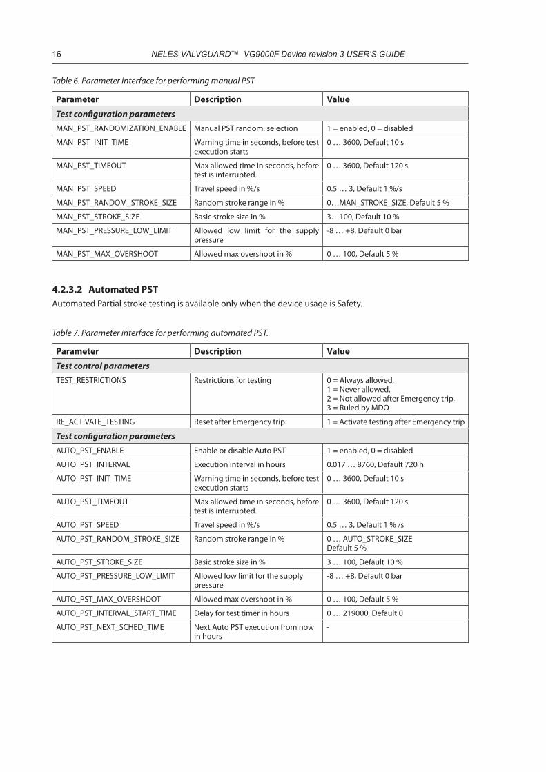
4.2.3.2 Automated PSTAutomated Partial stroke testing is available only when the device usage is Safety.
Table 7. Parameter interface for performing automated PST.
Parameter Description Value
Test control parametersTEST_RESTRICTIONS Restrictions for testing 0 = Always allowed,
1 = Never allowed, 2 = Not allowed after Emergency trip, 3 = Ruled by MDO
RE_ACTIVATE_TESTING Reset after Emergency trip 1 = Activate testing after Emergency trip
Test configuration parametersAUTO_PST_ENABLE Enable or disable Auto PST 1 = enabled, 0 = disabled
AUTO_PST_INTERVAL Execution interval in hours 0.017 … 8760, Default 720 h
AUTO_PST_INIT_TIME Warning time in seconds, before test execution starts
0 … 3600, Default 10 s
AUTO_PST_TIMEOUT Max allowed time in seconds, before test is interrupted.
0 … 3600, Default 120 s
AUTO_PST_SPEED Travel speed in %/s 0.5 … 3, Default 1 % /s
AUTO_PST_RANDOM_STROKE_SIZE Random stroke range in % 0 … AUTO_STROKE_SIZEDefault 5 %
AUTO_PST_STROKE_SIZE Basic stroke size in % 3 … 100, Default 10 %
AUTO_PST_PRESSURE_LOW_LIMIT Allowed low limit for the supply pressure
-8 … +8, Default 0 bar
AUTO_PST_MAX_OVERSHOOT Allowed max overshoot in % 0 … 100, Default 5 %
AUTO_PST_INTERVAL_START_TIME Delay for test timer in hours 0 … 219000, Default 0
AUTO_PST_NEXT_SCHED_TIME Next Auto PST execution from now in hours
-

NELES VALVGUARD™ VG9000F Device revision 3 USER’S GUIDE 17
4.2.3.3 PST resultsPartial stroke test results are shown in KEY_FIG_PST parameter, which is vector of 10 floats.
Table 8. PST test results (example values) reported in KEY_FIG_PST
Parameter ExampleTest Starting time in hours 23 h
Temperature when test started 18.3 °C
Supply pressure when test started 5.3 bar
Breakaway pressure during the test 2.1 bar
Load factor during the test 35 %
Targeted stroke size 10 %
Measured stroke size 9.9 %
Test type (130 = Auto PST, 131 = Manual PST) 131
Minimum pressure difference during test -
Reserved -
4.2.4 Emergency Trip TestEmergency trip test (ETT) diagnoses the availability of fail-safe action within given requirements. It is a full-stroke valve test performed at full speed recording the start time, temperature and supply pressure. Stroking times are recorded for both directions, and stroking time values are used as alarm limits with specified toler-ance.
ETT can only be started manually and is available in Safety and Hybrid usage modes.
Table 9. Parameter interface for performing ETT
Parameter Description Value
Test control parametersTEST_TYPE Test type selection 135 = ETT
TEST_CTRL Test command 1 = Start test, 2 = Cancel
TEST_STATUS Status of running test 1 = Test was OK, 2 = Initializing, 3 = Running, 4 = Cancelled (table 12)
TEST_RESTRICTIONS Restrictions for testing 0 = Always allowed, 1 = Never allowed, 2 = Not allowed after Emergency trip, 3 = Ruled by MDO
RE_ACTIVATE_TESTING Reset after Emergency trip 1 = Activate testing after Emergency trip
Test configuration parametersETT_ENABLE Enable or disable ETT 1 = enabled,
0 = disabled
ETT_INIT_TIME Warning time in seconds, before test execution starts
0 … 3600, Default 10 s
ETT_TIMEOUT Max allowed time in seconds, before test is interrupted.
0 … 3600, Default 100 s
ETT_STAY_TIME Not supported in this revision -
ETT test results are shown in KEY_FIG_ETT parameter, which is a vector of 10 floats.

18 NELES VALVGUARD™ VG9000F Device revision 3 USER’S GUIDE
Table 10. ETT test results (example values) are reported in KEY_FIG_ETT
Parameter ExampleTest Starting time in hours 23 h
Temperature when the test started 18.3 °C
Supply pressure when the test started 5.3 bar
Reserved -
Reserved -
Stroke time for opening direction 10 s
Stroke time for closing direction 3 s
Reserved -
Reserved -
Reserved -
4.2.5 Pneumatics TestPneumatics test checks all the safety loop-related functions in VG9000F. The test moves the spool valve slightly for a certain period of time, but without a risk that the valve position will change. With a pneumatics test, the operability of the intelligent safety solenoid can be confirmed.
Pneumatics test is triggered either automatically or manually or it can be environment (i.e. supply pressure) triggered.
Pneumatics testing is available in all device usage modes.
Table 11. Parameter interface for performing Pneumatics test
Parameter Description Value
Test control parametersTEST_TYPE (manual test) Test type selection 133 = Pneumatics test
TEST_CTRL (manual test) Test command 1 = Start test, 2 = Cancel
TEST_STATUS (manual test) Status of running test 1 = Test was OK, 2 = Initializing, 3 = Running, 4 = Cancelled (table 12)
TEST_RESTRICTIONS Restrictions for testing 0 = Always allowed, 1 = Never allowed, 2 = Not allowed after Emergency trip, 3 = Ruled by MDO
RE_ACTIVATE_TESTING Reset after Emergency trip 1 = Activate testing after Emergency trip
Test configuration parametersPNEUM_TEST_ENABLE Enable or disable automated pneu-
matics testing1 = enabled, 0 = disabled
PNEUM_TEST_INTERVAL Test interval in hours 0.18 … 8760, Default 24 h
PNEUM_TEST_INIT_TIME Warning time in seconds, before test execution starts
0 … 3600, Default 0 s
Pneumatics test results are shown in KEY_FIG_PNEUMATICS_TEST parameter, which is a vector of 10 floats.

NELES VALVGUARD™ VG9000F Device revision 3 USER’S GUIDE 19
Table 12. Pneumatics test results (example values) reported in KEY_FIG_PNEUMATICS_TEST
Parameter ExampleTest Starting time in hours 23 h
Temperature when the test started 18.3 °C
Supply pressure when the test started 5.3 bar
Valve position when test started 100 %
Test type (132 = Automated, 133 = Manual) 133
Failure code (table 12) 1
Reserved -
Reserved -
Reserved -
Reserved -
4.2.6 Test error messagesThe error messages that may occur in Partial Stroke test, Emergency Trip test or Pneumatics test are described in the next table.
Table 12. Test error messages (failure codes) in parameter TEST_STATUS
Description ValueTest Successful 1
Test Initializing 2
Test Running 3
Test Cancelled 4
Test Parameters Incorrect 5
Test Failed 6
Last Item 7
Data Not Ready 8
Failed In Key Figure Calculation 9
Failed In Channels Reserve 10
Supply Pressure Out Of Limits 11
Test Interrupted 12
Test Successful 128
Failed In Channels Reserve 129
Supply Pressure Out Of Limits 130
Invalid Target Position 131
Invalid Control Signal 132
Invalid Test Type 133
Test Start Retry 134
Failed In Mode Change 135
Invalid Random Position 136
Test Timeout 137
Invalid Warning Timeout 138
Timeout Expired 139
Invalid Data Selector 140
Invalid Initialization 141

20 NELES VALVGUARD™ VG9000F Device revision 3 USER’S GUIDE
Table 12. Test error messages (failure codes) in parameter TEST_STATUS
Description ValueTest in Disabled Mode 142
Invalid Hardware 143
Test Module Initialization 144
Supply Pressure Drop 145
Emergency Trip Active 146
Invalid Test Starting Position 147
Pressure Not Changed In Pneumatics Test 148
Testing Not Allowed due to Test Restrictions 149
Alarm State Prevents Testing 150
Unallowed Device Usage 151
Unallowed Device Type 152
Pneumatics Test Pressure Limit Too Close To Current Pressure 153
4.2.7 Trend graphs
4.2.7.1 Time-based trendsTrends are continuously saved in the device memory. Time-based trends show the values for the previous 30 days, 12 months and up to 25 years. In addition, trends show a Now-value, which is an average value of the previous 0-24 hours. Figure 3 shows a sample trend.
Figure 3. An example of a time-based trend graph.
The time axis of the trend is from left to right, with oldest values on the left and newest values on the right. The trend is adjusted periodically along the time as follows:
• When 24 hours have passed, a new daily value is added to the trend and the device begins calculating a new Now-value
• When 30 days have passed, a new monthly value is added to the trend• When 12 months have passed and 12 new monthly values have been calculated, a new yearly value is
added to the trendVG9000F provides time-based trends for supply pressure (average/min/max), temperature (average/min/max) and valve opening/closing times and valve opening/closing times deviation.
NELES VALVGUARD™ VG9000F Device revision 3 USER’S GUIDE 21
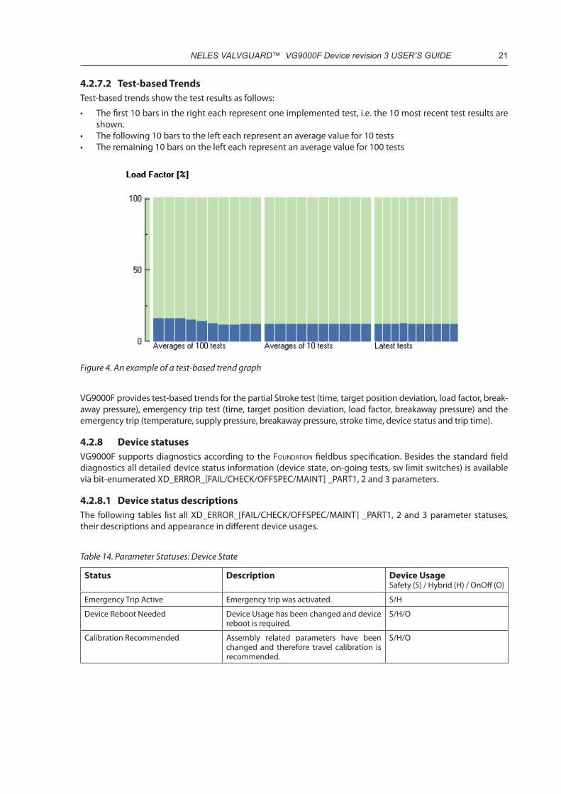
4.2.7.2 Test-based TrendsTest-based trends show the test results as follows:
• The first 10 bars in the right each represent one implemented test, i.e. the 10 most recent test results are shown.
• The following 10 bars to the left each represent an average value for 10 tests• The remaining 10 bars on the left each represent an average value for 100 tests
Figure 4. An example of a test-based trend graph
VG9000F provides test-based trends for the partial Stroke test (time, target position deviation, load factor, break-away pressure), emergency trip test (time, target position deviation, load factor, breakaway pressure) and the emergency trip (temperature, supply pressure, breakaway pressure, stroke time, device status and trip time).
4.2.8 Device statuses VG9000F supports diagnostics according to the Foundation fieldbus specification. Besides the standard field diagnostics all detailed device status information (device state, on-going tests, sw limit switches) is available via bit-enumerated XD_ERROR_[FAIL/CHECK/OFFSPEC/MAINT] _PART1, 2 and 3 parameters.
4.2.8.1 Device status descriptionsThe following tables list all XD_ERROR_[FAIL/CHECK/OFFSPEC/MAINT] _PART1, 2 and 3 parameter statuses, their descriptions and appearance in different device usages.
Table 14. Parameter Statuses: Device State
Status Description Device UsageSafety (S) / Hybrid (H) / OnOff (O)
Emergency Trip Active Emergency trip was activated. S/H
Device Reboot Needed Device Usage has been changed and device reboot is required.
S/H/O
Calibration Recommended Assembly related parameters have been changed and therefore travel calibration is recommended.
S/H/O

22 NELES VALVGUARD™ VG9000F Device revision 3 USER’S GUIDE
Table 15. Parameter Statuses: Test State
Status Description Device UsageSafety (S) / Hybrid (H) / OnOff (O)
Testing Not Allowed Testing cannot be started due to restrictions S/H/O
Test Initializing Partial stroke test, emergency trip test or pneumatics test is starting
S/H/O
Test Running Partial stroke test, emergency trip test or pneumatics test is running
S/H/O
Automated Partial Stroke Test Active Automated partial stroke test is running S
Manual Partial Stroke Test Active Manual partial stroke test is running S/H
Emergency Trip Test Active Emergency trip test is running S/H
Pneumatics Test Active Pneumatics test is running S/H/O
Table 16. Parameter Statuses: Software Limit Switches
Status Description Device UsageSafety (S) / Hybrid (H) / OnOff (O)
Limit Switch Close Activated Device is considered to be closed. S/H/O
Limit Switch Open Activated Device is considered to be open. S/H/O
Table 17. Parameter Statuses: Self Diagnostics
Status Description Device UsageSafety (S) / Hybrid (H) / OnOff (O)
Pressure Sensor 1 Failure Detected Pressure sensor #1 defect has been detected. S/H/O
Pressure Sensor 2 Failure Detected Pressure sensor #2 defect has been detected. S/H/O
Pressure Sensor 3 Failure Detected Pressure sensor #3 defect has been detected. S/H/O
Pneumatics Problem Detected Actuator pressure difference has not changed even it should have been. Spool valve may be jammed.
S/H/O
Position Sensor Failure Detected Position sensor defect has been detected. S/H/O
Position Sensor Out Of Range Too narrow position sensor range was detected in position calibration process.
S/H/O
Temperature Sensor Failure Detected Temperature sensor defect has been detected.
S/H/O
Prestage Cut Detected Prestage wire is cut or connector is loose. S/H/O
Spool Valve Stuck Detected Spool valve is not moving when it should and may be jammed.
S/H/O
Table 18. Parameter Statuses: Lifecycle Trends
Status Description Device UsageSafety (S) / Hybrid (H) / OnOff (O)
Temperature Trend Low Limit Exceeded
Temperature trend value has exceeded the configurable limits.
S/H/O
Temperature Trend High Limit Exceeded
Temperature trend value has exceeded the configurable limits.
S/H/O
Supply Pressure Trend Low Limit Exceeded
Supply pressure trend value has exceeded the configurable limits.
S/H/O
Supply Pressure Trend High Limit Exceeded
Supply pressure trend value has exceeded the configurable limits.
S/H/O

NELES VALVGUARD™ VG9000F Device revision 3 USER’S GUIDE 23
Table 19. Parameter Statuses: Counter Diagnostics
Status Description Device UsageSafety (S) / Hybrid (H) / OnOff (O)
Total Operation Time Counter Limit Exceeded
Total operating time has exceeded the configurable limit.
S/H/O
Valve Full Strokes Counter Limit Exceeded
Valve full stroke count has exceeded the configurable limit.
S/H/O
Actuator Full Strokes Counter Limit Exceeded
Actuator full stroke counter has exceeded the configurable limit.
S/H/O
Partial Stroke Test Counter Limit Exceeded
Partial stroke test counter has exceeded the configurable limit.
S/H
Table 20. Parameter Statuses: Online Diagnostics
Status Description Device UsageSafety (S) / Hybrid (H) / OnOff (O)
Supply Pressure Limit Exceeded Supply pressure is out of status limits. S/H/O
Supply Pressure Drop Detected Supply pressure has dropped below user configurable limit. This is an instant detec-tion.
S/H/O
Housing Pressure Limit Exceeded Pressure inside the housing has exceeded the configurable limit.
S/H/O
Temperature Limit Exceeded Temperature is out of configurable status limits.
S/H/O
Valve Open Stuck Detected Over 5 % difference between setpoint and valve position. Valve may be jammed at open position. Difference is a user configur-able parameter.
S/H/O
Valve Close Stuck Detected Over 5 % difference between setpoint and valve position. Valve may be jammed at close position. Difference is a user configur-able parameter.
S/H/O
Valve Intermediate Stuck Detected Over 5 % difference between setpoint and valve position. Valve may be stuck between open and close positions. Difference is a user configurable parameter.
S/H/O
Unintended Valve Movement Detected
Valve position has changed but setpoint is still in open or close position.
S/H/O
Valve Opening Time High Limit at Full Speed Exceeded
Valve opening at full speed is slower than user configurable limit allows.
S/H/O
Valve Closing Time High Limit at Full Speed Exceeded
Valve closing in full speed is slower than user configurable limit allows.
S/H/O
Table 21. Parameter Statuses: Test Diagnostics
Status Description Device UsageSafety/Hybrid/OnOff
Partial Stroke Test Pressure Drop Detected
Pressure drop detected in manual or auto-matic partial stroke test. This applies only for single acting actuators.
S/H
Partial Stroke Test Overshoot Detected Overshoot detected in manual or automatic partial stroke test.
S/H
Partial Stroke Test Breakaway Pressure Trend Low Limit Exceeded
Too low breakaway pressure detected in manual or automatic partial stroke test.
S/H
Partial Stroke Test Breakaway Pressure Trend High Limit Exceeded
Too high breakaway pressure detected in manual or automatic partial stroke test.
S/H
Partial Stroke Test Load Factor Trend Low Limit Exceeded
Too low load factor detected in manual or automatic partial stroke test.
S/H
Partial Stroke Test Load Factor Trend High Limit Exceeded
Too high load factor detected in manual or automatic partial stroke test.
S/H

24 NELES VALVGUARD™ VG9000F Device revision 3 USER’S GUIDE
4.2.8.2 Device status reportingThe Transducer block supports standard block alarming (reports about Out of Service mode) and device state reporting through the Resource block.
When field diagnostics detects active error condition in Failed category, this is reported in the BLOCK_ERR of Resource block as Device needs maintenance now.
When field diagnostics detects active error condition in Maintenance or Off specification categories, this is reported in the BLOCK_ERR of Resource block as Device needs maintenance now.
NAMUR NE107 categorized alarms are reported in FD_FAIL_ALM, FD_OFFSPEC_ALM, FD_MAINT_ALM and FD_CHECK_ALM parameters of Resource block.
4.2.9 Event logThe Event log (EVENT_LOG_EVENT) contains the 25 most recent device events. The related 25 Event log times are located in EVENT_LOG_EVENT_TIME_STAMP. The Event log times are presented in a form of operation hours.
Table 22. Parameter interface for Event log handling.
Parameter Value and description
EVENT_LOG_SELECTOR 1 = show last 25 events,
2 = show next 25 events,
3 = show previous 25 events
EVENT_LOG_STATUS 0 = ready, start of data,
1 = ready, 2 = ready, end of data,
3 = fetching data, 4 = error
EVENT_LOG_TIME_STAMP vector of 25 floats, event log time in operation hours
EVENT_LOG_EVENT vector of 25 integers, events
4.2.10 ParametersAll transducer block parameters are presented in the next table.
Table 23. Transducer block parameters
Transducer block parameter name Description
CONFIGURATIONST_REV The revision level of the static data associated with the function block. The
revision value will be incremented each time a static parameter value in this block is changed. Device Usage: Safety, Hybrid and On/Off.Default: 0
TAG_DESC The user description of the intended application of the block. Device Usage: Safety, Hybrid and On/Off.Default: nulls
STRATEGY The strategy field can be used to identify grouping of blocks. This data is not checked or processed by the block. Device Usage: Safety, Hybrid and On/Off.Default: 0
ALERT_KEY The identification number of the plant unit. This information may be used in the host for sorting alarms, etc. Device Usage: Safety, Hybrid and On/Off.Default: 0

NELES VALVGUARD™ VG9000F Device revision 3 USER’S GUIDE 25
Transducer block parameter name DescriptionMODE_BLK MODE_BLK contains the actual, target, permitted, and normal modes of the
block.• ACTUAL is the current mode of the block, which may differ from the
target based on operating conditions. Its value is calculated as part of block execution.
• TARGET is the mode requested by the operator. Only one mode from those allowed by the permitted mode parameter may be requested.
• PERMITTED defines the modes which are allowed for an instance of the block. The permitted mode is configured based on application require-ment.
• NORMAL is the mode which the block should be set to during normal operating conditions.
Transducer block modes are:• Out of Service (O/S) - O/S mode stops all function block execution. The
actual mode of the function blocks in this resource will be changed to O/S, but the target mode will not be changed.
• Automatic (Auto) - Auto mode allows normal operation of the resource.Device Usage: Safety, Hybrid and On/Off.Default: Target Auto
BLOCK_ERR This parameter reflects the error status associated with the hardware or soft-ware components associated with a block. It is a bit string, so that multiple errors may be shown.
• OK• Device Fault state• Device needs maintenance soon• Input Failure• Output Failure• Memory Failure• Lost Static Data• Lost NV Data• Readback Check• Device needs maintenance now• Power Up• Out of Service• Device Usage: Safety, Hybrid and On/Off.
Default: 0
UPDATE_EVT An alert for any change in the static data, UPDATE_EVT, is included in each block. This alert can notify interface devices that keep track of changes that one or more changes have occurred. The relative parameter index and its associated block index is included in the alert, along with the new value of ST_REV. If more than one change was added since the last reported Update Alert, as known from the difference between the last copy of ST_REV and the one in the alert, it will be necessary for the interface device to update all static data. No alert will be generated while a block is in Out of Service mode, so that downloads will not generate many update alerts. ST_REV will be incremented for each change to static data that occurs while the block is in the O/S mode. On the transition out of O/S mode, an update alert may be generated if the value of ST_REV for the block does not match that of the last reported alert. Update Alert has a fixed priority of 2, therefore it is auto-acknowledged (no operator intervention is required). Device Usage: Safety, Hybrid and On/Off.Default: 0;0;0,0;0
BLOCK_ALM Subcode = BLOCK_ERRDevice Usage: Safety, Hybrid and On/Off.Default: 0;0;0,0;0
TRANSDUCER_DIRECTORY A directory that specifies the number and starting indices of the transducers in the transducer block.Device Usage: Safety, Hybrid and On/Off.Default: 0
TRANSDUCER_TYPE Identifies the type of transducer. Device Usage: Safety, Hybrid and On/Off.Default: 106

26 NELES VALVGUARD™ VG9000F Device revision 3 USER’S GUIDE
Transducer block parameter name DescriptionXD_ERROR Transducer error codes.
• OK• Unspecified error (not supported)• General error (not supported)• Calibration error (not supported)• Configuration error (not supported)• Electronics Failure (not supported)• Mechanical Failure (not supported)• I/O Failure (not supported)• Data Integrity Error (not supported)• Software Error (not supported)• Algorithm Error (not supported)
Device Usage: Safety, Hybrid and On/Off.Default: 0 (OK)
COLLECTION_DIRECTORY A directory that specifies the number, starting indices, and DD Item Ids of the data collections in each transducer within a transducer block. Device Usage: Safety, Hybrid and On/Off.Default: 0
FINAL_VALUE Valve position setpoint after dead angle compensation, characterization, speed limiting, range limiting and cutoff functions. Device Usage: Safety, Hybrid and On/Off.Default: 0;0.0
FINAL_POSITION_VALUE The measured valve position. Device Usage: Safety, Hybrid and On/Off.Default: 0x0;0.0
ACT_MAN_ID The actuator manufacturer identification. Device Usage: Safety, Hybrid and On/Off.Default: 0
ACT_MODEL_NUM The actuator model number. Device Usage: Safety, Hybrid and On/Off.Default: -/-
ACT_SN The actuator serial number.Device Usage: Safety, Hybrid and On/Off.Default: -/-
VALVE_MAN_ID The valve manufacturer identification. Device Usage: Safety, Hybrid and On/Off.Default: 0
VALVE_MODEL_NUM The valve model number. Device Usage: Safety, Hybrid and On/Off.Default: -/-
VALVE_SN The valve serial number. Device Usage: Safety, Hybrid and On/Off.Default: -/-
XD_CAL_LOC The location of last positioner calibration. This describes the physical loca-tion at which the calibration was performed. Device Usage: Safety, Hybrid and On/Off.Default: -/-
XD_CAL_DATE The date of the last positioner calibration. Device Usage: Safety, Hybrid and On/Off.Default: 36526 (Uninitialized time)
XD_CAL_WHO The name of the person responsible for the last positioner calibration. Device Usage: Safety, Hybrid and On/Off.Default: -/-
ACTUATOR_TYPE Actuator type. • Undefined• Double acting actuator• Single acting actuator
Device Usage: Safety, Hybrid and On/Off.Default: Single acting actuator

NELES VALVGUARD™ VG9000F Device revision 3 USER’S GUIDE 27
Transducer block parameter name DescriptionVALVE_TYPE Valve type.
• Undefined• Linear• Rotary
Device Usage: Safety, Hybrid and On/Off.Default: Rotary
POSITIONER_FAIL_ACTION Positioner Fail Action. Set by user. • Undefined• Close. Position, where valve will be driven by mechanics, if there’s supply
pressure, but no power. • Open. Position, where valve will be driven by mechanics, if there’s supply
pressure, but no power. Device Usage: Safety, Hybrid and On/Off.Default: Close
EXTRA_INSTRUMENTATION_TYPE Type of extra instrumentation. • No extra instrumentation• Booster type 1• Booster type 2• Booster type 3• Quick exhaust 1• Quick exhaust 2• Quick exhaust 3• Combination of booster and quick exhaust 1• Combination of booster and quick exhaust 2• Combination of booster and quick exhaust 3
Device Usage: Safety, Hybrid and On/Off.Default: No extra instrumentation
EXTRA_INSTRUMENTATION_GAIN Gain for extra instrumentation. Device Usage: Safety and Hybrid.Default: 500Note: For service use only.
REVERSE_BOOSTER_STEP_SIZE_COEF Control parameter for pressure controller.Device Usage: Safety and Hybrid.Default: 1Note: For service use only.
CALIBRATION_DONE Informative parameter of executed calibrations.Device Usage: Safety, Hybrid and On/Off.Default: 0Note: For service use only
SUPPLY_COMPENSATION Spool supply pressure compensation term C.Device Usage: Safety, Hybrid and On/Off.Default: 1.1Note: For service use only
DEVICE_USAGE Actual device usage. • 0=Safety Device. Device is configured to act as an emergency isolation
purposes. Device follows only safety system DO control.• 1=On/off Device. Device is configured to act as a normal on/off valve
controller. Device follows DCS DO control. • 2=Hybrid Device. Device is configured to act as emergency isolation
purposes. The same time device can follow Foundation based opening/closing commands for valve operation. Safety system DO control over-rides Foundation based commands.
Device Usage: Safety, Hybrid and On/Off.Default: Safety Device
DEVICE_USAGE_TARGET Targeted device usage. Takes place in device boot. • 0=Safety Device• 1=On/off Device• 2=Hybrid Device
Device Usage: Safety, Hybrid and On/Off.Default: Safety Device
SAFETY_INPUT_TYPE Safety input type. Device Usage: Safety and Hybrid.Default: De-energized to trip

28 NELES VALVGUARD™ VG9000F Device revision 3 USER’S GUIDE
Transducer block parameter name DescriptionSPOOL_TYPE Spool type.
• Undefined spool type• VG9_15 (or VG9_12)• VG9_35• VG9_37
Device Usage: Safety, Hybrid and On/Off.Default: VG9_15
ACTUATOR_SIZE Actuator size. • Undefined size• B1C6-9, B1J8 (<1 l/<61 in3)• B1C11-13, B1J10 (1-3 l/ 61-183 in3)• B1C17-25, B1J16 (3-10 l/ 183-610 in3)• B1C32, B1J20-25 (10-30 l/ 610-1831 in3)• B1C40-, B1J32- (>30 l/ >1831 in3)
Device Usage: Safety, Hybrid and On/Off.Default: B1C6-9, B1J8 (<1 l/<61 in3)
DEAD_ANGLE_COMP The á0 setting is made for Metso’s segment and ball valves. This setting takes into account the “dead angle” á0 of the ball valves. The entire signal range is then used for effective valve opening 90° - á0. Device Usage: Hybrid.Default: 0Note: Not in use
STROKE_PROFILE_OPEN Valve open and close profiles can be configured with Neles ValvGuard with the limitation set by valve assembly.
• Linear• Slow starting• Slow starting and ending• Equal percentage• Quick starting
Device Usage: Hybrid.Default: Linear
STROKE_PROFILE_CLOSE Valve open and close profiles can be configured for VG9000F with the limita-tion set by the valve assembly.
• Linear• Slow starting• Slow starting and ending• Equal percentage• Quick starting
Device Usage: Hybrid.Default: Linear
STROKE_TIME_OPEN Targeted opening time. Device Usage: Hybrid.Default: 10 s
STROKE_TIME_CLOSE Targeted closing time. Device Usage: Hybrid.Default: 10 s
TESTING_RESTRICTIONS • Testing restrictions. • Always allowed• Never allowed• Not allowed after Emergency Trip until reactivate• Ruled by MDO block input
Device Usage: Safety and Hybrid.Default: Always allowed
REACTIVATE_TESTING Command to reactivate testing after Emergency Trip. • Idle• Activate
Device Usage: Safety and Hybrid.Default: 0
CALIBRATIONSELF_CALIB_CMD Initiation of a self-calibration-procedure. Note: Writable only in OOS (Out of
Service) mode. • Start travel calibration• Cancel travel calibration
Device Usage: Safety, Hybrid and On/Off.Default: 0

NELES VALVGUARD™ VG9000F Device revision 3 USER’S GUIDE 29
Transducer block parameter name DescriptionSELF_CALIB_STATUS Result or status of the self-calibration-procedure.
• Inactive• Cancelled• Error• Calibration running• Calibration successful
Device Usage: Safety, Hybrid and On/Off.Default: 0
SELF_CALIB_ERROR_CODE • Calibration Error Codes. • Calibration not initialized properly• An invalid operation was requested• Channel status was bad during calibration• The test timeout has expired• The state machines have entered to unknown state• Parameters write function failed when storing valve position• Valve position values difference too small• Calibration process was not able to get the temporary ownership• Parameters store in valve speed• Tried to start new calibration while other calibration is running• Tried to start calibration while emergency line is active• Supply pressure level too low to execute calibration• System failed to enter calibration mode• Critical parameter read failed.• Calibration request type out of range.• Device Usage: Safety, Hybrid and On/Off.
Default: 0
TESTINGAUTO_PST_ENABLE Automated Partial Stroke Test mode selection.
• Disabled• Enabled• Enabled and randomized
Device Usage: SafetyDefault: Disabled
AUTO_PST_INTERVAL Automated Partial Stroke Test run interval, in hours.Device Usage: SafetyDefault: 720 hRange: 0.017 … 8760 h
AUTO_PST_INIT_TIME Automated Partial Stroke Test warning time, in seconds. Delay for starting the test. Device Usage: SafetyDefault: 10 sRange: 0 … 3600 s
AUTO_PST_TIMEOUT Automated Partial Stroke Test timeout, in seconds. Time limit for test to be completed after warning time. Timeout cancels the test. Device Usage: SafetyDefault: 120 sRange: 0 … 3600
AUTO_PST_SPEED Automated Partial Stroke Test valve travel speed, in % / seconds. Device Usage: SafetyDefault: 1 %/s
AUTO_PST_STROKE_SIZE Automated Partial Stroke Test basic stroke size, in %.Device Usage: SafetyDefault: 10 %Range: 3 … 100 %
AUTO_PST_RANDOM_STROKE_SIZE Automated Partial Stroke Test randomized stroke size minimum, in %. Device Usage: SafetyDefault: 5.0 %
AUTO_PST_PRESSURE_LOW_LIMIT Automated Partial Stroke Test pressure low limit.Device Usage: SafetyDefault: 0.0 barRange: -8 … +8 bar
AUTO_PST_MAX_OVERSHOOT Automated Partial Stroke Test maximum overshoot allowed.Device Usage: SafetyDefault: 5.0 %Range: 0 … 100 %

30 NELES VALVGUARD™ VG9000F Device revision 3 USER’S GUIDE
Transducer block parameter name DescriptionAUTO_PST_INTERVAL_START_TIME Delay for the Automated Partial Stroke Test timer.
Device Usage: SafetyDefault: 0.0 hRange: 0 … 219000 h
AUTO_PST_NEXT_SCHED_TIME Automated Partial Stroke Test next scheduled time.Device Usage: Safety
MAN_PST_RANDOMIZATION_ENABLE Manual Partial Stroke Test randomization mode selection. • Disabled• Enabled
Device Usage: Safety and Hybrid.Default: Disabled
MAN_PST_INIT_TIME Manual Partial Stroke Test warning time, in seconds. Delay for starting the test. Device Usage: Safety and Hybrid.Default: 10.0 sRange: 0 … 3600 s
MAN_PST_TIMEOUT Manual Partial Stroke Test timeout, in seconds. Time limit for test to be completed after warning time. Timeout cancels the test. Device Usage: Safety and Hybrid.Default: 120.0 sRange: 0 … 3600 s
MAN_PST_SPEED Manual Partial Stroke Test valve travel speed, in % / seconds. Device Usage: Safety and Hybrid.Default: 1 %/sRange: 0.5 … 3 %/s
MAN_PST_RANDOM_STROKE_SIZE Manual Partial Stroke Test randomized stroke size.Device Usage: Safety and Hybrid.Default: 5 %
MAN_PST_STROKE_SIZE Manual Partial Stroke Test basic stroke size, in %.Device Usage: Safety and Hybrid.Default: 10 %Range: 3…100 s
MAN_PST_PRESSURE_LOW_LIMIT Manual Partial Stroke Test pressure low limit. Device Usage: Safety and Hybrid.Default: 0.0 barRange: -8 … +8 bar
MAN_PST_MAX_OVERSHOOT Manual Partial Stroke Test maximum overshoot.Device Usage: Safety and Hybrid.Default: 5 %Range: 0 … 100 %
ETT_ENABLE Manual Emergency Trip Test mode selection. • Disabled• Enabled
Device Usage: Safety and Hybrid.Default: Disabled
ETT_INIT_TIME Manual Emergency Trip Test warning time, in seconds. Delay for starting the test. Device Usage: Safety and Hybrid.Default: 10 sRange: 0 … 3600 s
ETT_TIMEOUT Manual Emergency Trip Test timeout, in seconds. Time limit for test to be completed after warning time. Timeout cancels the test. Device Usage: Safety and Hybrid.Default: 100 sRange: 0 … 3600 s
ETT_STAY_TIME Time for position to stay in turning point in Emergency Trip Test, in seconds. Device Usage: Safety and Hybrid. Default: 0 sNot in use
PNEUM_TEST_ENABLE Automated Pneumatics test mode. • Disabled• Enabled
Device Usage: Safety, Hybrid and On/Off.Default: Enabled
NELES VALVGUARD™ VG9000F Device revision 3 USER’S GUIDE 31
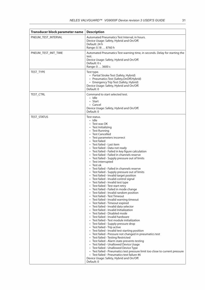
Transducer block parameter name DescriptionPNEUM_TEST_INTERVAL Automated Pneumatics Test Interval, in hours.
Device Usage: Safety, Hybrid and On/Off.Default: 24 hRange: 0.18 … 8760 h
PNEUM_TEST_INIT_TIME Automated Pneumatics Test warning time, in seconds. Delay for starting the test. Device Usage: Safety, Hybrid and On/Off. Default: 0 sRange: 0 … 3600 s
TEST_TYPE Test type. • Partial Stroke Test (Safety, Hybrid)• Pneumatics Test (Safety,OnOff,Hybrid)• Emergency Trip Test (Safety, Hybrid)
Device Usage: Safety, Hybrid and On/Off.Default: 0
TEST_CTRL Command to start selected test. • Idle• Start• Cancel
Device Usage: Safety, Hybrid and On/Off.Default: 0
TEST_STATUS Test status. • Idle• Test was OK• Test Initializing• Test Running• Test Cancelled• Test parameters incorrect• Test failed• Test failed - Last item• Test failed - Data not ready• Test failed - Failed in key figure calculation• Test failed - Failed in channels reserve• Test failed - Supply pressure out of limits• Test interrupted• Test ok• Test failed - Failed in channels reserve• Test failed - Supply pressure out of limits• Test failed - Invalid target position• Test failed - Invalid control signal• Test failed - Invalid test type• Test failed - Test start retry• Test failed - Failed in mode change• Test failed - Invalid random position• Test failed - Test Timeout• Test failed - Invalid warning timeout• Test failed - Timeout expired• Test failed - Invalid data selector• Test failed - Invalid Initialization• Test failed - Disabled mode• Test failed - Invalid hardware• Test failed - Test module initialization• Test failed - Supply pressure drop• Test failed - Trip active• Test failed - Invalid test starting position• Test failed - Pressure not changed in pneumatics test• Test failed - Testing Restricted• Test failed - Alarm state prevents testing• Test failed - Unallowed Device Usage• Test failed - Unallowed Device Type• Test failed - Pneumatics test pressure limit too close to current pressure• Test failed - Pneumatics test failure #6
Device Usage: Safety, Hybrid and On/Off.Default: 0

32 NELES VALVGUARD™ VG9000F Device revision 3 USER’S GUIDE
Transducer block parameter name DescriptionKEY_FIG_PST • Partial Stroke Test key figures.
• Partial Stroke Test starting time in operating hours• Device temperature when starting the partial stroke test• Supply pressure when starting the partial stroke test• Breakaway pressure during the partial stroke test.• Load factor during the partial stroke test• Target stroke size for the partial stroke test• Measured stroke size for the partial stroke test• Manual or Automated partial stroke test• Minimum pressure difference during PST
Device Usage: Safety and Hybrid.Default: 0.0,0.0,0.0,0.0,0.0,0.0,0.0,0.0,0.0,0.0
KEY_FIG_DETECTED_MOVEMENT The key figures of detected valve movement. • Detected movement time in operating hours• Device temperature when movement detected• Supply pressure when movement detected• Spool control value when movement detected • Safety line status when movement detected 0: Trip, 1: Spurious trip• Device status when movement detected
Device Usage: Safety and Hybrid.Default: 0.0,0.0,0.0,0.0,0.0,0.0,0.0,0.0,0.0,0.0
KEY_FIG_ETT Emergency Trip Test key figures. • Emergency Trip Test starting time in operating hours• Device temperature when starting the emergency trip test• Supply pressure when starting the emergency trip test• Reserved 1• Reserved 2• Stroke opening time during the emergency trip test• Stroke closing time during the emergency trip test
Device Usage: Safety and Hybrid.Default: 0.0,0.0,0.0,0.0,0.0,0.0,0.0,0.0,0.0,0.0
KEY_FIG_TRIP Emergency Trip key figures. • Emergency Trip starting time in operating hours• Device temperature when emergency trip occurred• Supply pressure when emergency trip occurred• Reserved 1• Stroke time for the emergency trip• Device status when emergency trip occurred
Device Usage: Safety and Hybrid.Default: 0.0,0.0,0.0,0.0,0.0,0.0,0.0,0.0,0.0,0.0
KEY_FIG_PNEUMATICS_TEST Pneumatics Test key figures. • Pneumatics Test starting time in operating hours. Device Usage: Safety
and Hybrid.• Temperature when starting the pneumatics test. Device Usage: Safety
and Hybrid.• Supply pressure when starting the pneumatics test. Device Usage:
Safety and Hybrid.• Valve position when starting the pneumatics test. Device Usage: Safety
and Hybrid.• Manual or Automated or Environment triggered pneumatics test.
Device Usage: Safety and Hybrid.• Reason for possible failure: see TEST_STATUS
Device Usage: Safety, Hybrid and On/Off.Default: 0.0,0.0,0.0,0.0,0.0,0.0,0.0,0.0,0.0,0.0
TEST_DATA_INDEX Default: 0For internal use
TEST_DATA_SELECTOR Default: 0For internal use
TEST_DATA_STATUS Default: 0For internal use
TEST_DATA Default: 0For internal use

NELES VALVGUARD™ VG9000F Device revision 3 USER’S GUIDE 33
Transducer block parameter name DescriptionDIAGNOSTICS
SW_LIMIT_SWITCH_OPEN Open value for software limit switch. Same or higher value of the valve posi-tion measurement means the valve is in open position. Device Usage: Safety, Hybrid and On/Off.Default: 99 %
SW_LIMIT_SWITCH_CLOSE Close value for software limit switch. Same or smaller value of the valve posi-tion measurement means the valve is in closed position.Device Usage: Safety, Hybrid and On/Off.Default: 1 %
STROKE_OPEN_TIME_DEV_WARN_LIM Default: 0.0Note: Not in use
STROKE_CLOSE_TIME_DEV_WARN_LIM Default: 0.0Note: Not in use
COMM_FAIL_RATE_ALARM_LIM Default: 1.0Note: Not in use
DEVICE_TEMPERATURE_LO_ALARM_LIM Limit for too low device temperature. Device Usage: Safety, Hybrid and On/Off.Default: -40 °C
DEVICE_TEMPERATURE_HI_ALARM_LIM Limit for too high device temperature. Device Usage: Safety, Hybrid and On/Off.Default: 85 °C
DEVICE_TEMPERATURE_LATCH_TIME Latch time before alert is generated for temperature above/below related parameters. Device Usage: Safety, Hybrid and On/Off.Default: 120 s
DEVICE_TEMP_TREND_LO_WARN_LIM Trend limit for too low device temperature. Device Usage: Safety, Hybrid and On/Off.Default: -35 °C
DEVICE_TEMP_TREND_HI_WARN_LIM Trend limit for too low device temperature. Device Usage: Safety, Hybrid and On/Off.Default: 80 °C
VALVE_STUCK_DEV_ALARM_LIM Limit for setpoint/position deviation in valve stuck detection. Setpoint changes, but valve doesn’t move.Device Usage: Safety, Hybrid and On/Off.Default: 5 %
VALVE_STUCK_DEV_LATCH_TIME Latch time for setpoint/position deviation in valve stuck detection. Device Usage: Safety, Hybrid and On/Off.Default: 5 s
UNINTENDED_MOVEMENT_LATCH_TIME Latch time for setpoint/position deviation in unintended movement detec-tion. Latch time is activated when valve position deviates more than 1 %. Valve moves, but setpoint remains stable. Device Usage: Safety, Hybrid and On/Off.Default: 0.1 s
TOTAL_OPERATION_TIME_WARN_LIM Detection limit for device total operation time.Device Usage: Safety, Hybrid and On/Off.Default: 216000.0 h
VALVE_STROKE_COUNTER_WARN_LIM Detection limit for valve full strokes. Device Usage: Safety, Hybrid and On/Off.Default: 2000000
ACT_STROKE_COUNTER_WARN_LIM Detection limit for actuator full strokes. Device Usage: Safety, Hybrid and On/Off.Default: 2000000
SUPPLY_PRESSURE_LO_ALARM_LIM Detection limit for too low supply pressure. Device Usage: Safety, Hybrid and On/Off.Default: 3 barG
SUPPLY_PRESSURE_HI_ALARM_LIM Detection limit for too high supply pressure. Device Usage: Safety, Hybrid and On/Off.Default: 7.5 barG
SUPPLY_PRESSURE_LATCH_TIME Latch time before alert is generated for supply pressure above/below related parameters. Device Usage: Safety, Hybrid and On/Off.Default: 30 s

34 NELES VALVGUARD™ VG9000F Device revision 3 USER’S GUIDE
Transducer block parameter name DescriptionSUPPLY_PRESSURE_DROP_WARN_LIM Detection limit for sudden supply pressure drop.
Device Usage: Safety, Hybrid and On/Off.Default: 1 barG
SUPPLY_PRES_TREND_LO_WARN_LIM Trend limit for too low supply pressure. Device Usage: Safety, Hybrid and On/Off.Default: 3,5 barG
SUPPLY_PRES_TREND_HI_WARN_LIM Trend limit for too high supply pressure. Device Usage: Safety, Hybrid and On/Off.Default: 7,5 barG
HOUSING_PRESSURE_LIM Status limit for housing pressure. Device Usage: Safety, Hybrid and On/Off.Default: 0.2 barG
PNEUMATICS_PROBLEM_LATCH_TIME Detection time for changing actuator cylinder pressure. Device Usage: Safety and Hybrid.Default: 15 s
PST_COUNTER_HI_LIM Detection limit for Partial stroke test counter. Device Usage: Safety and Hybrid.Default: 20000
PST_BREAKAWAY_LO_LIM Limit for too low Partial stroke test breakaway pressure. Device Usage: Safety and Hybrid.Default: 0 bar
PST_BREAKAWAY_HI_LIM Limit for too high Partial stroke test breakaway pressure. Device Usage: Safety and Hybrid.Default: 6 bar
PST_LOADFACTOR_TREND_LO_LIM Trend limit for too low Partial stroke test load factor.Device Usage: Safety and Hybrid.Default: 0 %
PST_LOADFACTOR_TREND_HI_LIM Trend limit for too high Partial stroke test load factor.Device Usage: Safety and Hybrid.Default: 50 %
STROKE_TIME_OPEN_LIM Trend limit for too slow valve open time in Emergency trip test. Device Usage: Safety, Hybrid and On/Off.Default: 10 s
STROKE_TIME_CLOSE_LIM Trend limit for too slow valve close time in Emergency trip test. Device Usage: Safety, Hybrid and On/Off.Default: 10 s
NBR_VALVE_FULL_STROKES Valve full stroke counter. Resettable. Device Usage: Safety, Hybrid and On/Off.Default: 0
NBR_ACTUATOR_FULL_STROKES Actuator full stroke counter. Resettable. Device Usage: Safety, Hybrid and On/Off.Default: 0
NBR_PARTIAL_STROKE_TESTS Partial stroke test counter. Resettable. Device Usage: Safety and Hybrid.Default: 0
NBR_PNEUMATIC_TESTS Pneumatics test counter. Resettable. Device Usage: Safety, Hybrid and On/Off.Default: 0
NBR_EMERGENCY_TRIP_TESTS Emergency trip test counter. Resettable. Device Usage: Safety and Hybrid.Default: 0
NBR_EMERGENCY_TRIPS Emergency trip counter. Device Usage: Safety and Hybrid.Default: 0
NBR_REBOOTS Counter of device restarts (configuration and diagnostics part). Device Usage: Safety, Hybrid and On/Off.Default: 0
NBR_UNINTENDED_MOVEMENTS Counter of unintended movements. Device Usage: Safety, Hybrid and On/Off.Default: 0

NELES VALVGUARD™ VG9000F Device revision 3 USER’S GUIDE 35
Transducer block parameter name DescriptionNBR_COMM_ERRS_DURING_LAST_MIN Detected Foundation communication failures during last minute.
Device Usage: Safety, Hybrid and On/Off.Default: 0
RESET_DIAGNOSTICS Reset diagnostics• Reset Valve travel counters. Device Usage: Safety, Hybrid and On/Off.• Reset Actuator travel counters. Device Usage: Safety, Hybrid and On/Off.• Reset all time based trends. Device Usage: Safety, Hybrid and On/Off.• Reset event log. Device Usage: Safety, Hybrid and On/Off.• Reset all diagnostics. Device Usage: Safety, Hybrid and On/Off.• Reset Partial stroke test counter. Device Usage: Safety and Hybrid.• Reset pneumatics test counter. Device Usage: Safety, Hybrid and On/Off.• Reset Emergency trip test counter. Device Usage: Safety and Hybrid.• Reset Partial stroke test trends. Device Usage: Safety and Hybrid.• Reset Emergency trip test trends. Device Usage: Safety and Hybrid.• Reset Emergency trip key figures. Device Usage: Safety and Hybrid.• Reset all test based trends. Device Usage: Safety and Hybrid.• Reset alarm status. Device Usage: Safety, Hybrid and On/Off.• Reset warning status. Device Usage: Safety, Hybrid and On/Off• Reset info status. Device Usage: Safety, Hybrid and On/Off
Default: 0
TREND_SELECTOR Trend selector• Trend selector for Average Supply pressure. Device Usage: Safety, Hybrid
and On/Off.• Trend selector for Supply pressure Minimum. Device Usage: Safety,
Hybrid and On/Off.• Trend selector for Supply pressure Maximum. Device Usage: Safety,
Hybrid and On/Off.• Trend selector for Average temperature. Device Usage: Safety, Hybrid
and On/Off.• Trend selector for Minimum Temperature. Device Usage: Safety, Hybrid
and On/Off.• Trend selector for Maximum Temperature. Device Usage: Safety, Hybrid
and On/Off.• Trend selector for Total valve opening time. Device Usage: Hybrid and
On/Off• Trend selector for Valve opening deviation time. Device Usage: Hybrid.• Trend selector for Total valve closing time. Device Usage: Hybrid and On/
Off• Trend selector for Valve closing deviation time. Device Usage: Hybrid.• Trend selector for first Partial stroke test timestamp. Device Usage:
Safety and Hybrid.• Trend selector for last Partial stroke test timestamp. Device Usage: Safety
and Hybrid.• Trend selector for Partial stroke test target position deviation. Device
Usage: Safety and Hybrid.• Trend selector for Partial stroke test load factory. Device Usage: Safety
and Hybrid.• Trend selector for Partial stroke test breakaway pressure. Device Usage:
Safety and Hybrid.• Trend selector for first Emergency trip test timestamp. Device Usage:
Safety and Hybrid.• Trend selector for last Emergency trip test timestamp. Device Usage:
Safety and Hybrid.• Trend selector for Emergency trip test valve opening time. Device Usage:
Safety and Hybrid.• Trend selector for Emergency trip test valve closing time. Device Usage:
Safety and Hybrid.• Selector for five latest Emergency trip temperature key figures. Device
Usage: Safety and Hybrid.• Selector for five latest Emergency trip supply pressure key figures.
Device Usage: Safety and Hybrid.• Selector for five latest Emergency trip breakaway key figures. Device
Usage: Safety and Hybrid.• Selector for five latest Emergency trip stroke time key figures. Device
Usage: Safety and Hybrid.• Selector for five latest Emergency trip device status key figures. Device
Usage: Safety and Hybrid.• Selector for five latest Emergency trip time key figures. Device Usage:
Safety and Hybrid.Default: 0
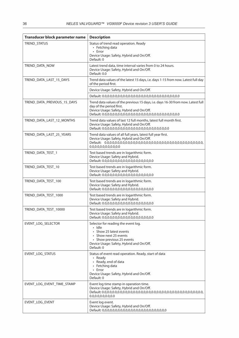
36 NELES VALVGUARD™ VG9000F Device revision 3 USER’S GUIDE
Transducer block parameter name DescriptionTREND_STATUS Status of trend read operation. Ready
• Fetching data• Error
Device Usage: Safety, Hybrid and On/Off.Default: 0
TREND_DATA_NOW Latest trend data, time interval varies from 0 to 24 hours. Device Usage: Safety, Hybrid and On/Off.Default: 0.0
TREND_DATA_LAST_15_DAYS Trend data values of the latest 15 days, i.e. days 1-15 from now. Latest full day of the period first.
Device Usage: Safety, Hybrid and On/Off.
Default: 0.0,0.0,0.0,0.0,0.0,0.0,0.0,0.0,0.0,0.0,0.0,0.0,0.0,0.0,0.0
TREND_DATA_PREVIOUS_15_DAYS Trend data values of the previous 15 days, i.e. days 16-30 from now. Latest full day of the period first. Device Usage: Safety, Hybrid and On/Off.Default: 0.0,0.0,0.0,0.0,0.0,0.0,0.0,0.0,0.0,0.0,0.0,0.0,0.0,0.0,0.0
TREND_DATA_LAST_12_MONTHS Trend data values of last 12 full months, latest full month first. Device Usage: Safety, Hybrid and On/Off.Default: 0.0,0.0,0.0,0.0,0.0,0.0,0.0,0.0,0.0,0.0,0.0,0.0,0.0
TREND_DATA_LAST_25_YEARS Trend data values of all full years, latest full year first. Device Usage: Safety, Hybrid and On/Off.Default: 0.0,0.0,0.0,0.0,0.0,0.0,0.0,0.0,0.0,0.0,0.0,0.0,0.0,0.0,0.0,0.0,0.0,0.0,0.0, 0.0,0.0,0.0,0.0,0.0,0.0
TREND_DATA_TEST_1 Test based trends are in logarithmic form. Device Usage: Safety and Hybrid.Default: 0.0,0.0,0.0,0.0,0.0,0.0,0.0,0.0,0.0,0.0
TREND_DATA_TEST_10 Test based trends are in logarithmic form. Device Usage: Safety and Hybrid.Default: 0.0,0.0,0.0,0.0,0.0,0.0,0.0,0.0,0.0,0.0
TREND_DATA_TEST_100 Test based trends are in logarithmic form. Device Usage: Safety and Hybrid.Default: 0.0,0.0,0.0,0.0,0.0,0.0,0.0,0.0,0.0,0.0
TREND_DATA_TEST_1000 Test based trends are in logarithmic form. Device Usage: Safety and Hybrid.Default: 0.0,0.0,0.0,0.0,0.0,0.0,0.0,0.0,0.0,0.0
TREND_DATA_TEST_10000 Test based trends are in logarithmic form. Device Usage: Safety and Hybrid.Default: 0.0,0.0,0.0,0.0,0.0,0.0,0.0,0.0,0.0,0.0
EVENT_LOG_SELECTOR Selector for reading the event log.• Idle• Show 25 latest events• Show next 25 events• Show previous 25 events
Device Usage: Safety, Hybrid and On/Off.Default: 0
EVENT_LOG_STATUS Status of event read operation. Ready, start of data• Ready• Ready, end of data• Fetching data• Error
Device Usage: Safety, Hybrid and On/Off.Default: 0
EVENT_LOG_EVENT_TIME_STAMP Event log time stamp in operation time. Device Usage: Safety, Hybrid and On/Off.Default: 0.0,0.0,0.0,0.0,0.0,0.0,0.0,0.0,0,0.0,0.0,0.0,0.0,0.0,0.0,0.0,0.0,0.0,0.0,0.0, 0.0,0.0,0.0,0.0,0.0
EVENT_LOG_EVENT Event log event. Device Usage: Safety, Hybrid and On/Off.Default: 0,0,0,0,0,0,0,0,0,0,0,0,0,0,0,0,0,0,0,0,0,0,0,0,0
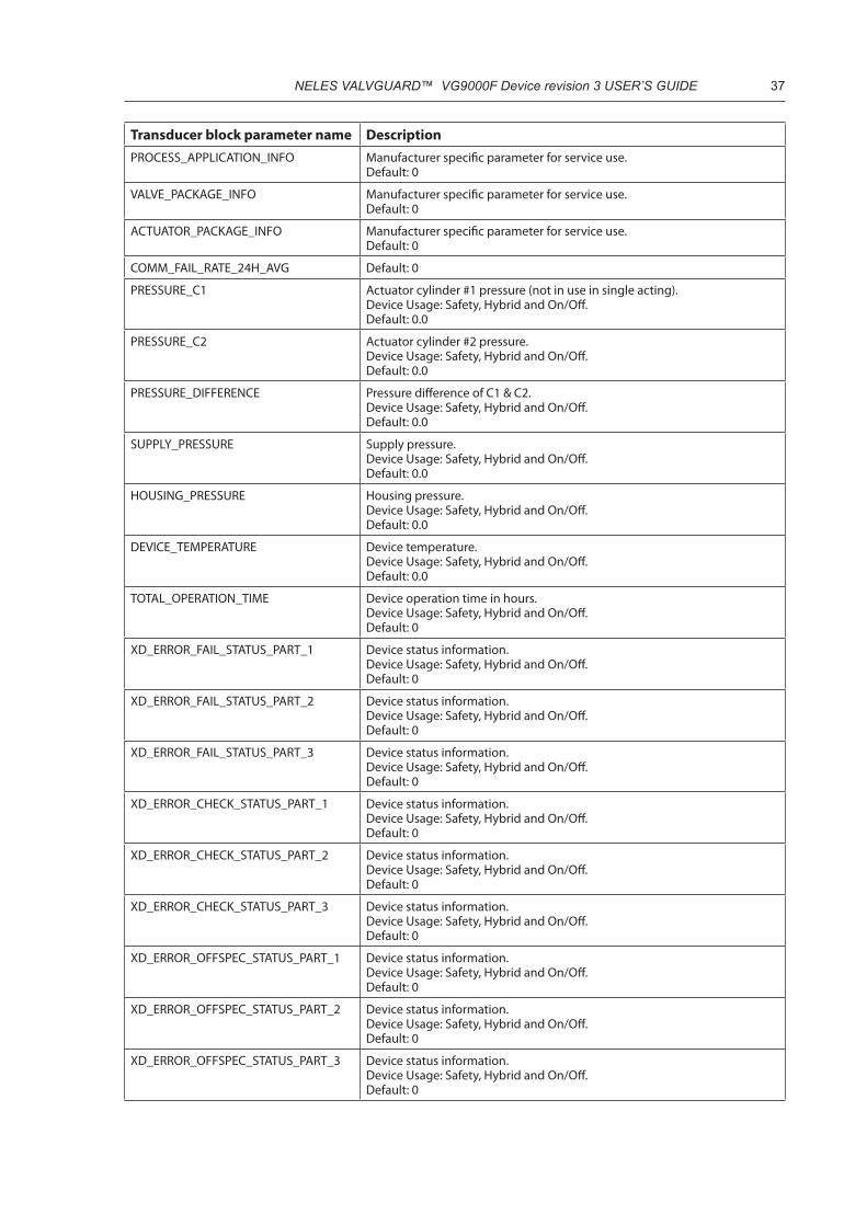
NELES VALVGUARD™ VG9000F Device revision 3 USER’S GUIDE 37
Transducer block parameter name DescriptionPROCESS_APPLICATION_INFO Manufacturer specific parameter for service use.
Default: 0
VALVE_PACKAGE_INFO Manufacturer specific parameter for service use.Default: 0
ACTUATOR_PACKAGE_INFO Manufacturer specific parameter for service use.Default: 0
COMM_FAIL_RATE_24H_AVG Default: 0
PRESSURE_C1 Actuator cylinder #1 pressure (not in use in single acting). Device Usage: Safety, Hybrid and On/Off.Default: 0.0
PRESSURE_C2 Actuator cylinder #2 pressure.Device Usage: Safety, Hybrid and On/Off.Default: 0.0
PRESSURE_DIFFERENCE Pressure difference of C1 & C2. Device Usage: Safety, Hybrid and On/Off.Default: 0.0
SUPPLY_PRESSURE Supply pressure. Device Usage: Safety, Hybrid and On/Off.Default: 0.0
HOUSING_PRESSURE Housing pressure.Device Usage: Safety, Hybrid and On/Off.Default: 0.0
DEVICE_TEMPERATURE Device temperature. Device Usage: Safety, Hybrid and On/Off.Default: 0.0
TOTAL_OPERATION_TIME Device operation time in hours. Device Usage: Safety, Hybrid and On/Off.Default: 0
XD_ERROR_FAIL_STATUS_PART_1 Device status information. Device Usage: Safety, Hybrid and On/Off.Default: 0
XD_ERROR_FAIL_STATUS_PART_2 Device status information. Device Usage: Safety, Hybrid and On/Off.Default: 0
XD_ERROR_FAIL_STATUS_PART_3 Device status information. Device Usage: Safety, Hybrid and On/Off.Default: 0
XD_ERROR_CHECK_STATUS_PART_1 Device status information. Device Usage: Safety, Hybrid and On/Off.Default: 0
XD_ERROR_CHECK_STATUS_PART_2 Device status information. Device Usage: Safety, Hybrid and On/Off.Default: 0
XD_ERROR_CHECK_STATUS_PART_3 Device status information. Device Usage: Safety, Hybrid and On/Off.Default: 0
XD_ERROR_OFFSPEC_STATUS_PART_1 Device status information. Device Usage: Safety, Hybrid and On/Off.Default: 0
XD_ERROR_OFFSPEC_STATUS_PART_2 Device status information. Device Usage: Safety, Hybrid and On/Off.Default: 0
XD_ERROR_OFFSPEC_STATUS_PART_3 Device status information. Device Usage: Safety, Hybrid and On/Off.Default: 0

38 NELES VALVGUARD™ VG9000F Device revision 3 USER’S GUIDE
Transducer block parameter name DescriptionXD_ERROR_MAINT_STATUS_PART_1 Device status information.
Device Usage: Safety, Hybrid and On/Off.Default: 0
XD_ERROR_MAINT_STATUS_PART_2 Device status information. Device Usage: Safety, Hybrid and On/Off.Default: 0
XD_ERROR_MAINT_STATUS_PART_3 Device status information. Device Usage: Safety, Hybrid and On/Off.Default: 0
4.3 Multiple Discrete Input block (MDI)
4.3.1 OverviewMultiple Discrete Input block (MDI) takes the discrete valve position information from the Transducer block and makes it accessible through its’ OUT_D3 (valve open position) and OUT_D4 (valve closed position) parameters. The channel configuration defines whether the position information comes from the limit switches (selected channel is 11) or from the valve position sensor (selected channel is 12).
MDI block provides also field diagnostics conditions and testing status information:
• OUT_D1 value 1 means that there is currently a test active (PST, ETT or Pneumatics test) on the device.• OUT_D2 value 1 means that there is active condition in Failed category.• OUT_D5 value 1 that there is active condition in Maintenance category.• OUT_D6 value 1 that there is active condition in Off specification category• OUT_D7 value 1 that there is active condition in Check function category
The MDI block schematic is presented in Figure 5
Figure 5. MDI block schematic.

NELES VALVGUARD™ VG9000F Device revision 3 USER’S GUIDE 39
4.3.2 Parameters
Table 26. MDI block parameters.
MDI block parameter name MDI block parameter descriptionST_REV The revision level of the static data associated with the function block. The
revision value will be incremented each time a static parameter value in this block is changed.Default: 0
TAG_DESC The user description of the intended application of the block.Default: “ “
STRATEGY The strategy field can be used to identify grouping of blocks. This data is not checked or processed by the block.Default: 0
ALERT_KEY The identification number of the plant unit. This information may be used in the host for sorting alarms, etc.Default: 0
MODE_BLK MODE_BLK contains the actual, target, permitted, and normal modes of the block.
• ACTUAL is the current mode of the block, which may differ from the target based on operating conditions. Its value is calculated as part of block execution.
• TARGET is the mode requested by the operator. Only one mode from those allowed by the permitted mode parameter may be requested.
• PERMITTED defines the modes which are allowed for an instance of the block. The permitted mode is configured based on application require-ment.
• NORMAL is the mode which the block should be set to during normal operating conditions.
• MDI block modes are:• Out of Service (O/S) - The block is not being evaluated. The output is
maintained at last value. • Manual (Man) - The output is set directly by the operator through an
interface system.• Automatic (Auto) – The normal block algorithm is determining the
output valueDefault: Target O/S
BLOCK_ERR This parameter reflects the error status associated with the hardware or soft-ware components associated with a block. It is a bit string, so that multiple errors may be shown. The standard specifies following bit string enumera-tions for the block _err parameter:
• Other; Non-specific error active.• BlockConfiguration; Error detected in block configuration.• LinkConfiguration; Error detected in link configuration.• LocalOverride; Faultstate active.• DeviceFaultstate; Device faultstate set.• Device needs maintenance soon• InputFailure; Process variable has bad status.• OutputFailure; Failure detected in output hardware.• MemoryFailure; Memory error detected.• LostStaticData; Static parameters cannot be recovered.• LostNVData; Non-Volatile parameters cannot be recovered.• Device needs maintenance now• PowerUp; Recovery from power failure.• OutOfService; Block actual mode is Out of Service.
Default: 0
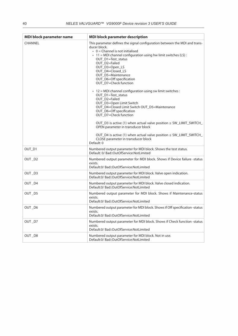
40 NELES VALVGUARD™ VG9000F Device revision 3 USER’S GUIDE
MDI block parameter name MDI block parameter descriptionCHANNEL This parameter defines the signal configuration between the MDI and trans-
ducer block.• 0 = Channel is not initialised• 11 = MDI channel configuration using hw limit switches (LS) :
OUT_D1=Test_status OUT_D2=Failed OUT_D3=Open_LS OUT_D4=Closed_LS OUT_D5=MaintenanceOUT_D6=Off specificationOUT_D7=Check function
• 12 = MDI channel configuration using sw limit switches : OUT_D1=Test_status OUT_D2=Failed OUT_D3=Open Limit Switch OUT_D4=Closed Limit Switch OUT_D5=MaintenanceOUT_D6=Off specificationOUT_D7=Check function
OUT_D3 is active (1) when actual valve position ≥ SW_LIMIT_SWITCH_OPEN parameter in transducer block
OUT_D4 is active (1) when actual valve position ≤ SW_LIMIT_SWITCH_CLOSE parameter in transducer block
Default: 0
OUT_D1 Numbered output parameter for MDI block. Shows the test status.Default: 0/ Bad::OutOfService:NotLimited
OUT _D2 Numbered output parameter for MDI block. Shows if Device failure -status exists.Default:0/ Bad::OutOfService:NotLimited
OUT _D3 Numbered output parameter for MDI block. Valve open indication.Default:0/ Bad::OutOfService:NotLimited
OUT _D4 Numbered output parameter for MDI block. Valve closed indication.Default:0/ Bad::OutOfService:NotLimited
OUT _D5 Numbered output parameter for MDI block. Shows if Maintenance-status exists.Default:0/ Bad::OutOfService:NotLimited
OUT _D6 Numbered output parameter for MDI block. Shows if Off specification -status exists.Default:0/ Bad::OutOfService:NotLimited
OUT _D7 Numbered output parameter for MDI block. Shows if Check function -status exists.Default:0/ Bad::OutOfService:NotLimited
OUT _D8 Numbered output parameter for MDI block. Not in use.Default:0/ Bad::OutOfService:NotLimited

NELES VALVGUARD™ VG9000F Device revision 3 USER’S GUIDE 41
MDI block parameter name MDI block parameter descriptionUPDATE_EVT An alert for any change in the static data, UDATE_EVT, is included in each
block. This alert can notify interface devices that keep track of changes that one or more changes have occurred. The relative parameter index and its associated block index is included in the alert, along with the new value of ST_REV. If more than one change was added since the last reported Update Alert, as known from the difference between the last copy of ST_REV and the one in the alert, it will be necessary for the interface device to update all static data. No alert will be generated while a block is in Out of Service mode, so that downloads will not generate many update alerts.ST_REV will be incremented for each change to static data that occurs while the block is in the O/S mode. On the transition out of O/S mode, an update alert may be generated if the value of ST_REV for the block does not match that of the last reported alert. Update Alert has a fixed priority of 2, therefore it is autoacknowledged (no operator intervention is required).
• Unacknowledged - A discrete enumeration which is set to Unacknowl-edged when an update occurs, and set to Acknowledged by a write from a human interface device or other entity which can acknowledge that the alarm has been noticed.
• Update State - A discrete enumeration which gives an indication of whether the alert has been reported.
• Time Stamp - The time when evaluation of the block was started and a change in alarm/event state was detected that is unreported. The time stamp value will be maintained constant until alert confirmation has been received - even if another change of state occurs.
• Static Rev - the static revision of the block whose static parameter was changed and is being reported. It is possible for the present value of static revision to be greater than this because static can be changed at any time.
• Relative Index - The OD index of the static parameter whose change caused this alert, minus the FB starting index. If the update event was caused by a write to multiple parameters at the same time, then this attribute will be zero.
Default: 0;0;0,0;0
BLOCK_ALM The block alarm is used for all configuration, hardware, connection failure or system problems in the block. The cause of the alert is entered in the subcode field. The first alert to become active will set the Active status in the Status attribute. As soon as the Unreported status is cleared by the alert reporting task, another block alert may be reported without clearing the Active status, if the subcode has changed.
• Unacknowledged - A discrete enumeration which is set to Unacknowl-edged when an update occurs, and set to Acknowledged by a write from a human interface device or other entity which can acknowledge that the alarm has been noticed.
• Update State - A discrete enumeration which gives an indication of whether the alert has been reported.
• Time Stamp - The time when evaluation of the block was started and a change in alarm/event state was detected that is unreported. The time stamp value will be maintained constant until alert confirmation has been received even if another change of state occurs.
• Subcode - An enumeration specifying the cause of the alert to be reported. Enumerations are equal with the BLOCK_ERR.
• Value - The value of the associated parameter at the time the alert was detected.
Default: 0;0;0,0;0

42 NELES VALVGUARD™ VG9000F Device revision 3 USER’S GUIDE
4.4 Multiple Discrete Output block (MDO)
4.4.1 OverviewMultiple Discrete Output block (MDO) takes the discrete input signal from the Foundation fieldbus and passes it to the Transducer block through the channel reference. The channel configuration (selected channel is 1), defines that:
• IN_D1 value change from 0 to 1 commands VG9000F to start one manual Partial Stroke Test (PST). IN_D1 status shall be Good, NonCascade
(in Safety and Hybrid usage mode)• IN_D2 value change from 0 to 1 commands VG9000F to cancel the PST. IN_D2 status shall be Good,
NonCascade (in Safety and Hybrid usage mode)• IN_D3 value change from 0 to 1 commands VG9000F to disable all testing. Value change from 1 to 0
commands VG9000F to enable all testing. As a default only manual PST is allowed. IN-D3 status shall be Good, NonCascade
(in Safety and Hybrid usage mode)• IN_D4 value 1 is passed to the valve controller as a discrete Open setpoint. IN_D4 value 0 is a discrete
Close setpoint for the valve controller. IN_D4 status shall be Good, NonCascade (in Hybrid usage mode)
Notice also TEST_RESTRICTIONS configuration and use RE_ACTIVATE_TESTING command when necessary.
Table 27. Test restrictions and re-activate testing.
TEST_RESTRICTIONS Restrictions for testing 0 = Always allowed1 = Never allowed2 = Not allowed after Emergency trip3 = Ruled by MDO
RE_ACTIVATE_TESTING Reset after Emergency trip 1 = Activate testing after Emergency trip
The MDO block schematic is presented in Figure 6.
Figure 6. MDO block schematic.
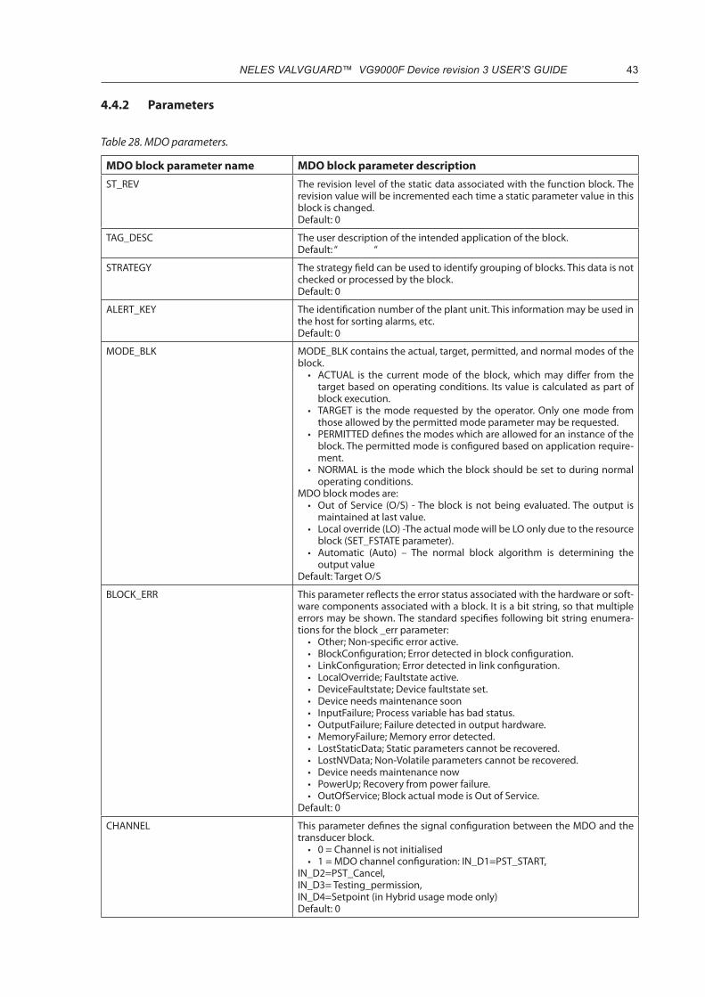
NELES VALVGUARD™ VG9000F Device revision 3 USER’S GUIDE 43
4.4.2 Parameters
Table 28. MDO parameters.
MDO block parameter name MDO block parameter descriptionST_REV The revision level of the static data associated with the function block. The
revision value will be incremented each time a static parameter value in this block is changed.Default: 0
TAG_DESC The user description of the intended application of the block.Default: “ “
STRATEGY The strategy field can be used to identify grouping of blocks. This data is not checked or processed by the block.Default: 0
ALERT_KEY The identification number of the plant unit. This information may be used in the host for sorting alarms, etc.Default: 0
MODE_BLK MODE_BLK contains the actual, target, permitted, and normal modes of the block.
• ACTUAL is the current mode of the block, which may differ from the target based on operating conditions. Its value is calculated as part of block execution.
• TARGET is the mode requested by the operator. Only one mode from those allowed by the permitted mode parameter may be requested.
• PERMITTED defines the modes which are allowed for an instance of the block. The permitted mode is configured based on application require-ment.
• NORMAL is the mode which the block should be set to during normal operating conditions.
MDO block modes are:• Out of Service (O/S) - The block is not being evaluated. The output is
maintained at last value. • Local override (LO) -The actual mode will be LO only due to the resource
block (SET_FSTATE parameter).• Automatic (Auto) – The normal block algorithm is determining the
output valueDefault: Target O/S
BLOCK_ERR This parameter reflects the error status associated with the hardware or soft-ware components associated with a block. It is a bit string, so that multiple errors may be shown. The standard specifies following bit string enumera-tions for the block _err parameter:
• Other; Non-specific error active.• BlockConfiguration; Error detected in block configuration.• LinkConfiguration; Error detected in link configuration.• LocalOverride; Faultstate active.• DeviceFaultstate; Device faultstate set.• Device needs maintenance soon• InputFailure; Process variable has bad status.• OutputFailure; Failure detected in output hardware.• MemoryFailure; Memory error detected.• LostStaticData; Static parameters cannot be recovered.• LostNVData; Non-Volatile parameters cannot be recovered.• Device needs maintenance now• PowerUp; Recovery from power failure.• OutOfService; Block actual mode is Out of Service.
Default: 0
CHANNEL This parameter defines the signal configuration between the MDO and the transducer block.
• 0 = Channel is not initialised• 1 = MDO channel configuration: IN_D1=PST_START,
IN_D2=PST_Cancel,IN_D3= Testing_permission, IN_D4=Setpoint (in Hybrid usage mode only)Default: 0

44 NELES VALVGUARD™ VG9000F Device revision 3 USER’S GUIDE
IN_D1 Numbered input parameter for MDO block. Used for PST start.Default:0/ Bad::OutOfService:NotLimited
IN_D2 Numbered input parameter for MDO block. Used for PST cancelDefault:0/ Bad::OutOfService:NotLimited
IN_D3 Numbered input parameter for MDO block. Used for Testing permission.Default:0/ Bad::OutOfService:NotLimited
IN_D4 Numbered input parameter for MDO block. Used for discrete setpoint (hybrid usage).Default:0/ Bad::OutOfService:NotLimited
IN_D5 Numbered input parameter for MDO block. Not in use.Default:0/ Bad::OutOfService:NotLimited
IN_D6 Numbered input parameter for MDO block. Not in use.Default:0/ Bad::OutOfService:NotLimited
IN_D7 Numbered input parameter for MDO block. Not in use.Default:0/ Bad::OutOfService:NotLimited
IN_D8 Numbered input parameter for MDO block. Not in use.Default:0/ Bad::OutOfService:NotLimited
MO_OPTS This parameter defines the options that the user may select to alter multiple output block processing.MO_OPTS bit enumerations are:
• Fault state to value 1 (LSB)*• Fault state to value 2• Fault state to value 3• Fault state to value 4• Fault state to value 5• Fault state to value 6• Fault state to value 7• Fault state to value 8• Use fault state value on restart 1• Use fault state value on restart 2• Use fault state value on restart 3• Use fault state value on restart 4• Use fault state value on restart 5• Use fault state value on restart 6• Use fault state value on restart 7• Use fault state value on restart 8
Default: 0
FSTATE_TIME The time in seconds from detection of fault of the output block remote setpoint to the output action of the block output if the condition still exists.Default:0.0
FSTATE_VAL_D1 The preset discrete value to use when failure occurs in IN_D1. Ignored if the “Fault state to value 1” in the MO_OPTS parameter is false.Default:0
FSTATE_VAL_D2 The preset discrete value to use when failure occurs in IN_D2. Ignored if the “Fault state to value 2” in the MO_OPTS parameter is false.Default:0
FSTATE_VAL_D3 The preset discrete value to use when failure occurs in IN_D3. Ignored if the “Fault state to value 3” in the MO_OPTS parameter is false.Default:0
FSTATE_VAL_D4 The preset discrete value to use when failure occurs in IN_D4. Ignored if the “Fault state to value 4” in the MO_OPTS parameter is false.Default:0
FSTATE_VAL_D5 The preset discrete value to use when failure occurs in IN_D5. Ignored if the “Fault state to value 5” in the MO_OPTS parameter is false.Default:0Not in use
FSTATE_VAL_D6 The preset discrete value to use when failure occurs in IN_D6. Ignored if the “Fault state to value 6” in the MO_OPTS parameter is false.Default:0Not in use

NELES VALVGUARD™ VG9000F Device revision 3 USER’S GUIDE 45
FSTATE_VAL_D7 The preset discrete value to use when failure occurs in IN_D7. Ignored if the “Fault state to value 7” in the MO_OPTS parameter is false.Default:0Not in use
FSTATE_VAL_D8 The preset discrete value to use when failure occurs in IN_D8. Ignored if the “Fault state to value 8” in the MO_OPTS parameter is false.Default:0Not in use
FSTATE_STATUS FSTATE_STATUS shows, which points are in fault state.Default:0
UPDATE_EVT An alert for any change in the static data, UDATE_EVT, is included in each block. This alert can notify interface devices that keep track of changes that one or more changes have occurred. The relative parameter index and its associated block index is included in the alert, along with the new value of ST_REV. If more than one change was added since the last reported Update Alert, as known from the difference between the last copy of ST_REV and the one in the alert, it will be necessary for the interface device to update all static data. No alert will be generated while a block is in Out of Service mode, so that downloads will not generate many update alerts.ST_REV will be incremented for each change to static data that occurs while the block is in the O/S mode. On the transition out of O/S mode, an update alert may be generated if the value of ST_REV for the block does not match that of the last reported alert. Update Alert has a fixed priority of 2, therefore it is autoacknowledged (no operator intervention is required).
• Unacknowledged - A discrete enumeration which is set to Unacknowl-edged when an update occurs, and set to Acknowledged by a write from a human interface device or other entity which can acknowledge that the alarm has been noticed.
• Update State - A discrete enumeration which gives an indication of whether the alert has been reported.
• Time Stamp - The time when evaluation of the block was started and a change in alarm/event state was detected that is unreported. The time stamp value will be maintained constant until alert confirmation has been received - even if another change of state occurs.
• Static Rev - the static revision of the block whose static parameter was changed and is being reported. It is possible for the present value of static revision to be greater than this because static can be changed at any time.
• Relative Index - The OD index of the static parameter whose change caused this alert, minus the FB starting index. If the update event was caused by a write to multiple parameters at the same time, then this attribute will be zero.
Default: 0;0;0,0;0
BLOCK_ALM The block alarm is used for all configuration, hardware, connection failure or system problems in the block. The cause of the alert is entered in the subcode field. The first alert to become active will set the Active status in the Status attribute. As soon as the Unreported status is cleared by the alert reporting task, another block alert may be reported without clearing the Active status, if the subcode has changed.
• Unacknowledged - A discrete enumeration which is set to Unacknowl-edged when an update occurs, and set to Acknowledged by a write from a human interface device or other entity which can acknowledge that the alarm has been noticed.
• Update State - A discrete enumeration which gives an indication of whether the alert has been reported.
• Time Stamp - The time when evaluation of the block was started and a change in alarm/event state was detected that is unreported. The time stamp value will be maintained constant until alert confirmation has been received even if another change of state occurs.
• Subcode - An enumeration specifying the cause of the alert to be reported. Enumerations are equal with the BLOCK_ERR.
• Value - The value of the associated parameter at the time the alert was detected.
Default: 0;0;0,0;0

46 NELES VALVGUARD™ VG9000F Device revision 3 USER’S GUIDE
4.5 Analog Input block
4.5.1 OverviewAnalog Input block (AI) takes the measured analog valve position information (0-100 %) from the Transducer block and makes it accessible through it’s OUT parameter. The channel configuration (selected channel is 21) defines, that position information comes from the valve position sensor.
The AI block schematic is presented in Figure 7.
Figure 7. AI block schematic.
4.5.2 Parameters
Table 29.AI parameters.
AI block parameter name AI block parameter descriptionST_REV The revision level of the static data associated with the function block. The
revision value will be incremented each time a static parameter value in this block is changed.Default: 0
TAG_DESC The user description of the intended application of the block.Default: “ “
STRATEGY The strategy field can be used to identify grouping of blocks. This data is not checked or processed by the block.Default: 0
ALERT_KEY The identification number of the plant unit. This information may be used in the host for sorting alarms, etc.Default: 0
MODE_BLK MODE_BLK contains the actual, target, permitted, and normal modes of the block.
• ACTUAL is the current mode of the block, which may differ from the target based on operating conditions. Its value is calculated as part of block execution.
• TARGET is the mode requested by the operator. Only one mode from those allowed by the permitted mode parameter may be requested.
• PERMITTED defines the modes which are allowed for an instance of the block. The permitted mode is configured based on application require-ment.
• NORMAL is the mode that the block should be set to during normal operating conditions.
• AI block modes are:• Out of Service (O/S) - The block is not being evaluated. The output is
maintained at last value. • Manual (Man) - The output is set directly by the operator through an
interface system.• Automatic (Auto) – The normal block algorithm is determining the
output valueDefault: Target O/S
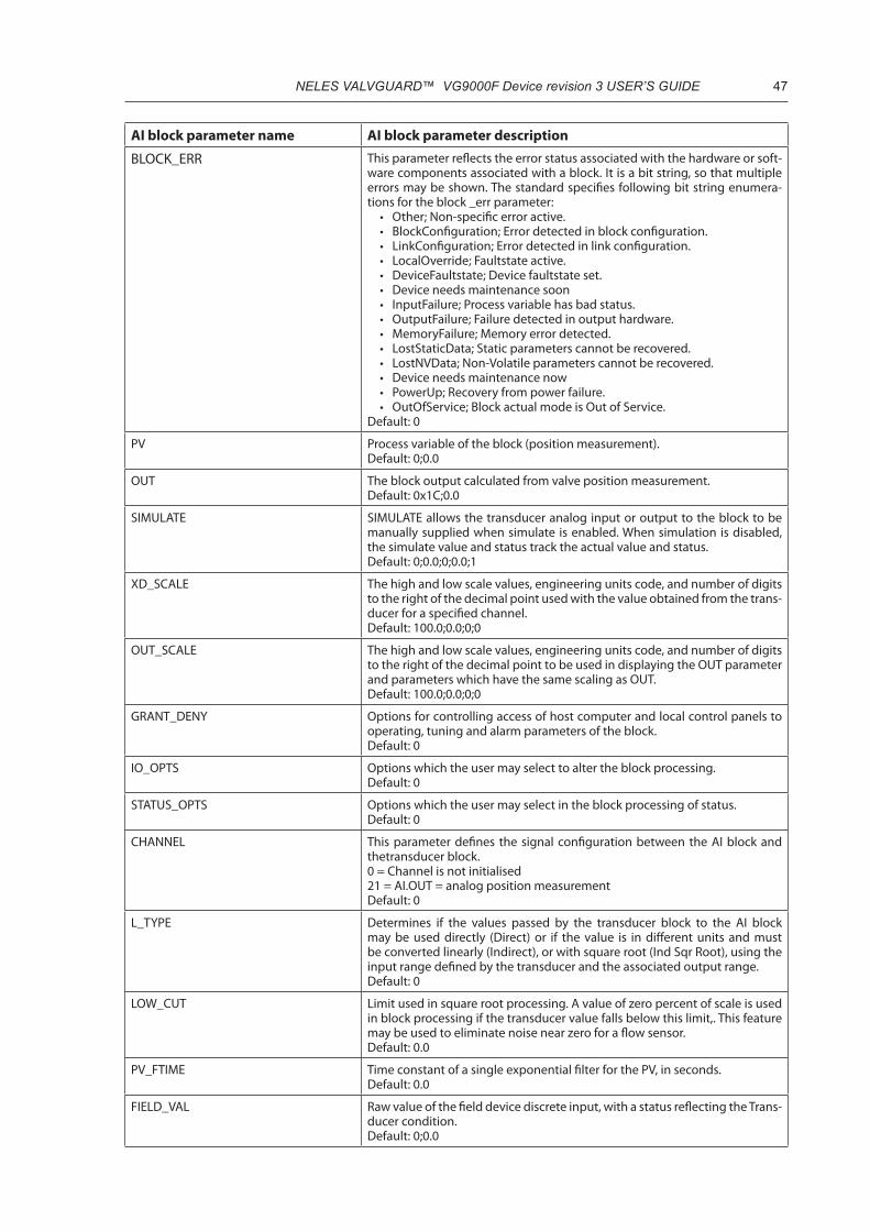
NELES VALVGUARD™ VG9000F Device revision 3 USER’S GUIDE 47
AI block parameter name AI block parameter description
BLOCK_ERR This parameter reflects the error status associated with the hardware or soft-ware components associated with a block. It is a bit string, so that multiple errors may be shown. The standard specifies following bit string enumera-tions for the block _err parameter:
• Other; Non-specific error active.• BlockConfiguration; Error detected in block configuration.• LinkConfiguration; Error detected in link configuration.• LocalOverride; Faultstate active.• DeviceFaultstate; Device faultstate set.• Device needs maintenance soon• InputFailure; Process variable has bad status.• OutputFailure; Failure detected in output hardware.• MemoryFailure; Memory error detected.• LostStaticData; Static parameters cannot be recovered.• LostNVData; Non-Volatile parameters cannot be recovered.• Device needs maintenance now• PowerUp; Recovery from power failure.• OutOfService; Block actual mode is Out of Service.
Default: 0
PV Process variable of the block (position measurement).Default: 0;0.0
OUT The block output calculated from valve position measurement.Default: 0x1C;0.0
SIMULATE SIMULATE allows the transducer analog input or output to the block to be manually supplied when simulate is enabled. When simulation is disabled, the simulate value and status track the actual value and status.Default: 0;0.0;0;0.0;1
XD_SCALE The high and low scale values, engineering units code, and number of digits to the right of the decimal point used with the value obtained from the trans-ducer for a specified channel.Default: 100.0;0.0;0;0
OUT_SCALE The high and low scale values, engineering units code, and number of digits to the right of the decimal point to be used in displaying the OUT parameter and parameters which have the same scaling as OUT.Default: 100.0;0.0;0;0
GRANT_DENY Options for controlling access of host computer and local control panels to operating, tuning and alarm parameters of the block.Default: 0
IO_OPTS Options which the user may select to alter the block processing.Default: 0
STATUS_OPTS Options which the user may select in the block processing of status.Default: 0
CHANNEL This parameter defines the signal configuration between the AI block and thetransducer block.0 = Channel is not initialised21 = AI.OUT = analog position measurement Default: 0
L_TYPE Determines if the values passed by the transducer block to the AI block may be used directly (Direct) or if the value is in different units and must be converted linearly (Indirect), or with square root (Ind Sqr Root), using the input range defined by the transducer and the associated output range.Default: 0
LOW_CUT Limit used in square root processing. A value of zero percent of scale is used in block processing if the transducer value falls below this limit,. This feature may be used to eliminate noise near zero for a flow sensor.Default: 0.0
PV_FTIME Time constant of a single exponential filter for the PV, in seconds.Default: 0.0
FIELD_VAL Raw value of the field device discrete input, with a status reflecting the Trans-ducer condition.Default: 0;0.0

48 NELES VALVGUARD™ VG9000F Device revision 3 USER’S GUIDE
AI block parameter name AI block parameter descriptionUPDATE_EVT An alert for any change in the static data, UDATE_EVT, is included in each
block. This alert can notify interface devices that keep track of changes that one or more changes have occurred. The relative parameter index and its associated block index is included in the alert, along with the new value of ST_REV. If more than one change was added since the last reported Update Alert, as known from the difference between the last copy of ST_REV and the one in the alert, it will be necessary for the interface device to update all static data. No alert will be generated while a block is in Out of Service mode, so that downloads will not generate many update alerts.ST_REV will be incremented for each change to static data that occurs while the block is in the O/S mode. On the transition out of O/S mode, an update alert may be generated if the value of ST_REV for the block does not match that of the last reported alert. Update Alert has a fixed priority of 2, therefore it is autoacknowledged (no operator intervention is required).
• Unacknowledged - A discrete enumeration which is set to Unacknowl-edged when an update occurs, and set to Acknowledged by a write from a human interface device or other entity which can acknowledge that the alarm has been noticed.
• Update State - A discrete enumeration which gives an indication of whether the alert has been reported.
• Time Stamp - The time when evaluation of the block was started and a change in alarm/event state was detected that is unreported. The time stamp value will be maintained constant until alert confirmation has been received - even if another change of state occurs.
• Static Rev - the static revision of the block whose static parameter was changed and is being reported. It is possible for the present value of static revision to be greater than this because static can be changed at any time.
• Relative Index - The OD index of the static parameter whose change caused this alert, minus the FB starting index. If the update event was caused by a write to multiple parameters at the same time, then this attribute will be zero.
Default: 0;0;0,0;0
BLOCK_ALM The block alarm is used for all configuration, hardware, connection failure or system problems in the block. The cause of the alert is entered in the subcode field. The first alert to become active will set the Active status in the Status attribute. As soon as the Unreported status is cleared by the alert reporting task, another block alert may be reported without clearing the Active status, if the subcode has changed.
• Unacknowledged - A discrete enumeration which is set to Unacknowl-edged when an update occurs, and set to Acknowledged by a write from a human interface device or other entity which can acknowledge that the alarm has been noticed.
• Update State - A discrete enumeration which gives an indication of whether the alert has been reported.
• Time Stamp - The time when evaluation of the block was started and a change in alarm/event state was detected that is unreported. The time stamp value will be maintained constant until alert confirmation has been received even if another change of state occurs.
• Subcode - An enumeration specifying the cause of the alert to be reported. Enumerations are equal with the BLOCK_ERR.
• Value - The value of the associated parameter at the time the alert was detected.
Default: 0;0;0,0;0
ALARM_SUM The current alert status, unacknowledged states, unreported states, and disabled states of the alarms associated with the function block.Default: 0;0;0;0
ACK_OPTION Selection of whether alarms associated with the block will be automatically acknowledged.Default: 0
ALARM_HYS Amount the PV must return within the alarm limits before the alarm condi-tion clears. Alarm hysteresis is expressed as a percent of the PV spanDefault: 0.5
HI_HI_PRI Priority of the high high alarm.Default: 0
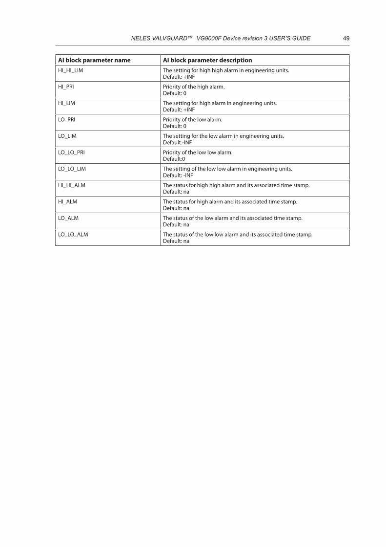
NELES VALVGUARD™ VG9000F Device revision 3 USER’S GUIDE 49
AI block parameter name AI block parameter descriptionHI_HI_LIM The setting for high high alarm in engineering units.
Default: +INF
HI_PRI Priority of the high alarm.Default: 0
HI_LIM The setting for high alarm in engineering units.Default: +INF
LO_PRI Priority of the low alarm.Default: 0
LO_LIM The setting for the low alarm in engineering units.Default:-INF
LO_LO_PRI Priority of the low low alarm.Default:0
LO_LO_LIM The setting of the low low alarm in engineering units.Default: -INF
HI_HI_ALM The status for high high alarm and its associated time stamp.Default: na
HI_ALM The status for high alarm and its associated time stamp.Default: na
LO_ALM The status of the low alarm and its associated time stamp.Default: na
LO_LO_ALM The status of the low low alarm and its associated time stamp.Default: na

50 NELES VALVGUARD™ VG9000F Device revision 3 USER’S GUIDE
5. LAS capabilityFoundation fieldbus communication requires always a device that takes care of the communication scheduling in a Fieldbus link. Terminology definition:
• LM = Link Master. Device is capable to operate as a LAS or as a spare LAS.• BASIC = Device that does not have LM capability.• LAS = Link Active Scheduler. LM type device that is currently taking care of the communication scheduling
in a Foundation fieldbus link.
In a normal case, the host system or HSE linking device acts as a LAS for the Fieldbus link. There can also be one or more spare LAS devices.
VG9000F is delivered from the factory as a BASIC device. It is possible to configure VG9000F as Link Master and after that, VG9000F is capable to operate as a spare LAS device.
VG9000F device type selection between BASIC/LM can be handled from the host system. Please consult your host system manufacturer for further instructions.

NELES VALVGUARD™ VG9000F Device revision 3 USER’S GUIDE 51

Metso Flow Control Inc.
Europe, Vanha Porvoontie 229, P.O. Box 304, FI-01301 Vantaa, Finland. Tel. +358 20 483 150. Fax +358 20 483 151North America, 44 Bowditch Drive, P.O. Box 8044, Shrewsbury, M A 01545, USA. Tel. +1 508 852 0200. Fax +1 508 852 8172
South America, Av. Independéncia, 2500-Iporanga, 18087-101, Sorocaba-São Paulo, Brazil. Tel. +55 15 2102 9700. Fax +55 15 2102 9748 Asia Paci�c, Haw Par Centre #06-01, 180 Clemenceau Avenue, Singapore 239922. Tel. +65 6511 1011. Fax +65 6250 0830
China, 11/F, China Youth Plaza, No.19 North Rd of East 3rd Ring Rd, Chaoyang District, Beijing 100020, China. Tel. +86 10 6566 6600. Fax +86 10 6566 2583.Middle East, Roundabout 8, Unit AB-07, P.O. Box 17175, Jebel Ali Freezone, Dubai, United Arab Emirates. Tel. +971 4 883 6974. Fax +971 4 883 6836
www.metso.com/valves
52 NELES VALVGUARD™ VG9000F Device revision 3 USER’S GUIDE


