
Veterinary Anesthesia Gas Scavenging System (Active) · 3.4 Installing the Scavenger Interface T...
16
10434800 Rev.GA1 2/7/18 Veterinary Anesthesia Gas Scavenging System (Active) Installation and Operation Manual MX103200i
Transcript of Veterinary Anesthesia Gas Scavenging System (Active) · 3.4 Installing the Scavenger Interface T...

10434800 Rev.GA1 2/7/18
Veterinary Anesthesia GasScavenging System (Active)Installation and Operation Manual
MX103200i


1
Table of ContentsSection 1 UNPACKING ........................................................................................2
1.1 Examining Packaged Components .......................................................2Section 2 DESCRIPTION & IDENTIFICATION ....................................................3
2.1 About the System ................................................................................. 32.2 About your Components ....................................................................... 3
Section 3 INSTALLATION ................................................................................... 53.1 Getting Started .....................................................................................53.2 Installing the Gas Disposal Vent Kit ...................................................... 53.3 Installing the Scavenger Interface ........................................................ 6
3.3.1 Wall Mount ..................................................................................63.3.2 Post Mount ................................................................................. 7
3.4 Installing the Scavenger Interface Tubing ............................................. 7Section 4 OPERATION ........................................................................................8
4.1 Operating your Anesthesia Gas Scavenging System (Active) .............. 84.2 Tips for Optimal Scavenger Interface Performance .............................. 8
Section 5 MAINTENANCE................................................................................... 95.1 General Cleaning and Replacement ..................................................... 95.2 Periodic Maintenance ........................................................................... 95.3 Troubleshooting Guide .........................................................................95.4 Replacement Parts ............................................................................. 10
Section 6 INFORMATION & WARRANTY ......................................................... 116.1 General Information............................................................................ 116.2 Return Goods Procedure ................................................................... 116.3 Warranty ............................................................................................. 11
Illustrations & ChartsFigure 1 Packaged Active Scavenger Interface Components ............................. 2Figure 2 Anesthesia Gas Scavenging System Configuration Options ................4Figure 3 Gas Disposal Vent Location ................................................................. 5Figure 4 Wall Mounting Scavenger Interface Bracket Mounting .......................... 6Figure 5 Post Mounting Scavenger Interface Bracket Mounting .........................7Figure 6 Interface ON / OFF Switch ...................................................................8Figure 7 Periodic Maintenance Chart ................................................................. 9Figure 8 Cleaning Interface Vents ....................................................................... 9Figure 9 Troubleshooting Chart ........................................................................ 10Figure 10 Replacement Parts Exploded View .................................................... 10
Safety SymbolsWARNINGIndicates a potentially hazardous situation
which could result in serious injury if not avoided.
NoteAmplifies a procedure, practice, or condition.
CAUTIONIndicates a potentially hazardous situation
which may result in minor or moderate injury if notavoided. It may also be used to alert against unsafepractices.
Equipment AlertIndicates a potentially hazardous situation
which could result in equipment damage if not avoided
2
AA
MX104600i
ON
OFF
K
L
J
I
M
NG
H
F
E
C
D
B
A
P
O Q
R S T U Y Z
V X
W
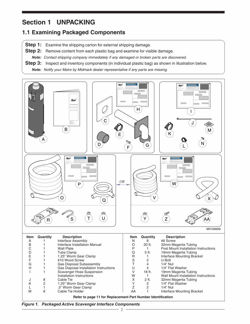
Step 1: Examine the shipping carton for external shipping damage.
Step 2: Remove content from each plastic bag and examine for visible damage.
Note: Contact shipping company immediately if any damaged or broken parts are discovered.
Step 3: Inspect and inventory components (in individual plastic bag) as shown in illustration below.
Note: Notify your Matrx by Midmark dealer representative if any parts are missing.
Section 1 UNPACKING
1.1 Examining Packaged Components
Figure 1. Packaged Active Scavenger Interface Components
Item Quantity DescriptionA 1 Interface AssemblyB 1 Interface Installation ManualC 1 Wall PlateD 1 Tube ClampE 1 1.25” Worm Gear ClampF 1 #10 Wood ScrewG 1 Gas Disposal SubassemblyH 1 Gas Disposal Installation InstructionsI 1 Scavenger Hose Suspension
Installation InstructionsJ 8 Cable TieK 2 1.25” Worm Gear ClampL 1 .5” Worm Gear ClampM 8 Cable Tie Holder
Item Quantity DescriptionN 8 #6 ScrewO 20 ft. 32mm Magenta TubingP 1 Post Mount Installation InstructionsQ 5 ft. 19mm Magenta TubingR 1 Interface Mounting BracketS 2 U-BoltT 4 1/4” NutU 4 1/4” Flat WasherV 18 ft. 19mm Magenta TubingW 1 Wall Mount Installation InstructionsX 2 ft. 32mm Magenta TubingY 2 1/4” Flat WasherZ 2 1/4” Nut
AA 1 Interface Mounting Bracket
Refer to page 11 for Replacement Part Number Identification
OR

3
Section 2 DESCRIPTION & IDENTIFICATION
2.1 About the SystemThis veterinary anesthesia scavenging system is intended for veterinary use only. It is not intended for use inhealth care facilities that provide services to human beings. This device is not intended for use with flammableanesthetics. Installation of this device and its components in a veterinary operatory should be made by compe-tent individuals.
The Matrx by Midmark Veterinary Anesthesia Gas Scavenging System (Active) is a device that captures excessanesthesia gas from the anesthesia machine and disperses it to the outside of your facility. This system can beused with any Matrx by Midmark Anesthesia Machine or with comparable machines. The Matrx by MidmarkVeterinary Anesthesia Gas Scavenging System (Active) can also be used with an extracorporeal oxygenator.
2.2 About your ComponentsThis Matrx by Midmark Veterinary Anesthesia Gas Scavenging System (Active) incorporates the followingcomponents with some supplied in individual kits (*).
SCAVENGER KIT:The scavenger interface provides positive and negative pressure relief , provides reservoir capacity, and directsthe collected gas to the Gas Disposal Vent through the disposal tubing. The interface may be mounted to eitherthe Anesthesia Machine’s base post or an exterior wall.
WARNINGThis devise is not intended for use with flammable anesthetics.
CAUTIONThis devise will exert pressures between atmospheric pressure and
-0.5 cm-H2O on an oxygenator gas vent. Compatibility must be checked.
WARNINGDo not install the Gas Disposal Kit through the ceiling or roof.
CAUTIONDo not clamp the transfer tubing to the APL valve.Do not allow the transfer tubing to run along the floor.
MOUNTING KIT (*):The Mounting Kit enables you to mount the interface to either a post or to an exterior (outside) wall. Refer toFigure 2 for an illustration depicting both of these mounting configurations.
GAS DISPOSAL KIT (*):The Gas Disposal Kit is designed to mount through an exterior wall of a building and to disperse the anestheticgas from your anesthesia machine to a disposal point that is normally isolated from personnel, doors, windows,and any air intake(s) or outlet(s).
TUBING KIT (*):TRANSFER TUBINGThe Transfer Tubing fastens to the outlet tube of the Gas Collecting Assembly (APL valve) on your Anesthesiamachine and the input port on the Active Scavenger System Interface, which is located on the bottom of theinterface. The Transfer Tubing is 19mm in diameter and magenta in color.
DISPOSAL TUBINGThe Disposal Tubing is 32mm in diameter and is also magenta in color. The Disposal Tubing fastens between theoutlet (downstream) opening which is located on top of the interface and the Gas Disposal Vent.

4
Section 2 DESCRIPTION & IDENTIFICATION (cont.)
2.2 About your Components (cont.)
MX103300i
MX103200i
Post Mount
ExteriorWall
Figure 2. Anesthesia Gas Scavenging System Configuration Options
Wall Mount
Gas Disposal KitComponents
AnesthesiaMachine
(not included)
Active ScavengerSystem Interface
Components(post mounted)
Post MountTubing Kit
Components
ExteriorWall
Gas Disposal KitComponents
AnesthesiaMachine
(not included)
Active ScavengerSystem Interface
Components(wall mounted)
Wall MountTubing Kit
ComponentsTotal Tubing FromAnesthesia Machine toExterior Wall Can Not
Exceed100 Ft.
Total Tubing FromAnesthesia Machine toExterior Wall Can Not
Exceed100 Ft.

5
Section 3 INSTALLATION
3.1 Getting StartedCheck the location you have selected to install your Gas Disposal Vent carefully to make sure it meets all safetyrequirements as explained in the Instructions. The kits and components should be installed in the following order:
Gas Disposal SystemScavenger InterfaceTubing
3.2 Installing the Gas Disposal Vent KitThe location of the access hole for the Gas Disposal Vent depends on whether your system is a wall-mounted orpost-mounted application. Refer to the illustrations in Figure 3 for correct vent hole placement. Complete the GasDisposal Kit installation in accordance with the Installation Instructions [10420300] supplied with this kit; it isimportant that you heed all safety alerts stated in the Installation Instructions.
MX104100i
Figure 3. Gas Disposal Vent Location
Wall Mount
Post Mount
ExistingWall Studs
VentHole
MountingBracket
6.62” (16.8 cm)from mounting
bracket
Make sure that thepower cord reaches
the outlet beforemounting interface
4’ (1.2 m)to
5’ (1.5m)from floor
6” (15.2 cm) from stud(Refer to WARNING on
Gas Disposal KitInstallation Instructions
[10428300])
VentHole
12’ (30 cm)to
18’ (45 cm)from ceiling
Anywhere between studs(Refer to WARNING on
Gas Disposal KitInstallation Instructions
[10428200])

6
Section 3 INSTALLATION (cont.)
3.3 Installing the Scavenger Interface
Figure 4. Wall Mounted Scavenger Interface Bracket Mounting
NoteCheck your location to make sure the tubing reaches from the anesthesia machine to the Interface and fromthe Interface to the Gas Disposal Vent (lengths vary based on interface mounting configuration [wall or post]).
Install the wall interface mounting bracket in accordance with the illustration in Figure 4. Once the mount hasbeen successfully secured, the interface can be hung on to the hanger mounting tabs.
NoteBefore mounting interface bracket to the wall, make sure the interface’s power cord will reach the nearestgrounded wall receptacle. Refer to “Wall Mount” illustration in Figure 3.
3.3.1 WALL MOUNT
MX104300i
MountingBracket
Step 2: Drill 5/32”(4mm) pilotholes into stud.
Step 1: Position bracket on wall andmark hole locations.
Note: Make sure to locate wall studand position bracket over stud.
Washer
Lag Bolt
Step 3: Insert washer and lag boltthrough upper and lowercenter mounting holes.
Note: Make sure tabs on the mountingbracket face upward.
Step 4: Slide Interface ontomounting bracket tabs.
Note: Make sure tabs on bothbrackets are fully engaged.
Interface

7
3.3.2 POST MOUNTInstall the post interface mounting bracket in accordance with the illustration in Figure 5. Once the mount hasbeen successfully secured, the interface can be hung on to the hanger mounting tabs.
Section 3 INSTALLATION (cont.)
3.3 Installing the Scavenger Interface (cont.)
Figure 5. Post Mounted Scavenger Interface Bracket Mounting
MX104200i
MountingBracket
Step 2: Slide U-bolts aroundpost and throughmounting holes inbracket.
Step 3: Install washers and nutsand secure to post.
Washer
Nut
Post
Step 4: Slide Interface ontomounting bracket tabs.
Note: Make sure tabs on bothbrackets are fully engaged.
U-bolt
Step 1: Position bracket onto post.
Note: Make sure tabs face upward.
3.4 Installing the Scavenger TubingComplete the tubing installation in accordance with the Tubing Kit Instructions (Post Mount [10428200] or(Wall Mount [10428300]) supplied with this kit. It is important that you heed any safety symbols and alerts statedin the Installation Instructions. Refer to Scavenging Hose Suspension Installation Instructions (10428100) for“Preferred” and “Alternate” tubing mounting methods.
WARNINGDo not install the tubing up through the roof or down along the floor.
*Total Tubing from Anesthesia Machine to Exterior WallCan Not Exceed 100 Ft.
8
Section 4 OPERATION
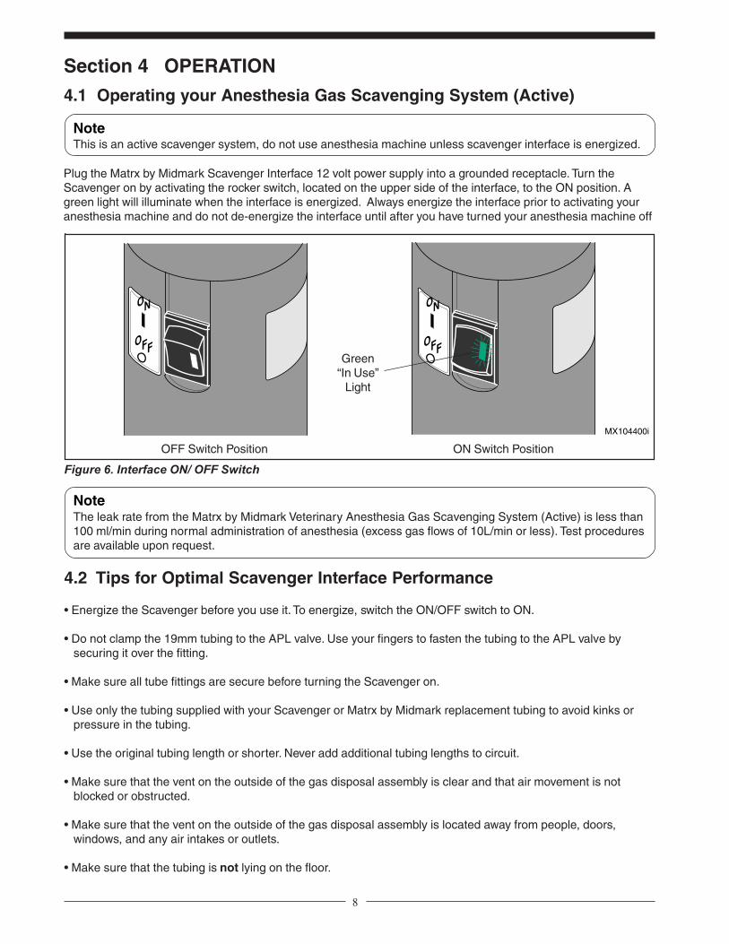
4.1 Operating your Anesthesia Gas Scavenging System (Active)
Figure 6. Interface ON/ OFF Switch
Plug the Matrx by Midmark Scavenger Interface 12 volt power supply into a grounded receptacle. Turn theScavenger on by activating the rocker switch, located on the upper side of the interface, to the ON position. Agreen light will illuminate when the interface is energized. Always energize the interface prior to activating youranesthesia machine and do not de-energize the interface until after you have turned your anesthesia machine off.
NoteThis is an active scavenger system, do not use anesthesia machine unless scavenger interface is energized.
NoteThe leak rate from the Matrx by Midmark Veterinary Anesthesia Gas Scavenging System (Active) is less than100 ml/min during normal administration of anesthesia (excess gas flows of 10L/min or less). Test proceduresare available upon request.
4.2 Tips for Optimal Scavenger Interface Performance
• Energize the Scavenger before you use it. To energize, switch the ON/OFF switch to ON.
• Do not clamp the 19mm tubing to the APL valve. Use your fingers to fasten the tubing to the APL valve by securing it over the fitting.
• Make sure all tube fittings are secure before turning the Scavenger on.
• Use only the tubing supplied with your Scavenger or Matrx by Midmark replacement tubing to avoid kinks or pressure in the tubing.
• Use the original tubing length or shorter. Never add additional tubing lengths to circuit.
• Make sure that the vent on the outside of the gas disposal assembly is clear and that air movement is not blocked or obstructed.
• Make sure that the vent on the outside of the gas disposal assembly is located away from people, doors, windows, and any air intakes or outlets.
• Make sure that the tubing is not lying on the floor.
ON Switch PositionOFF Switch Position
MX104400i
ON
OFF
ON
OFFGreen
“In Use”Light
9
MX104500i
ON
OFF
Thumbscrews
VentScreens
InterfaceOutlet
Assembly
InterfaceBody
Section 5 MAINTENANCE
5.1 General Cleaning and ReplacementInspect the Scavenger Interface and tubing circuit for damage before each use. If the unit appears to be dam-aged, do not use it; call your Matrx by Midmark Service Representative for replacement parts if necessary.
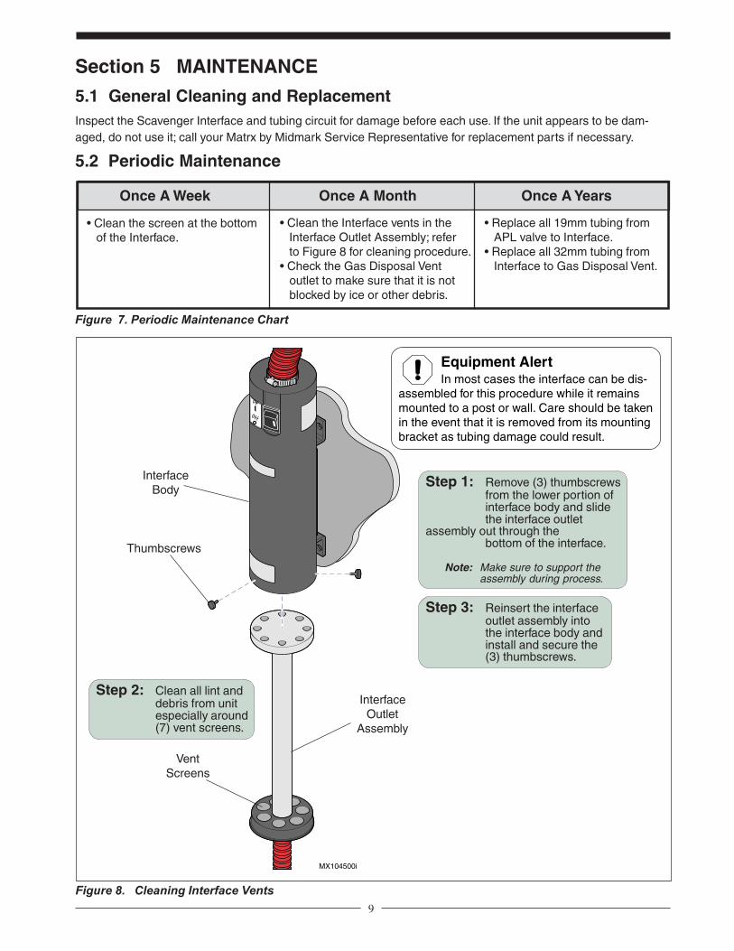
5.2 Periodic Maintenance
Once A Week Once A Month Once A Years
• Replace all 19mm tubing from APL valve to Interface.• Replace all 32mm tubing from Interface to Gas Disposal Vent.
• Clean the Interface vents in the Interface Outlet Assembly; refer to Figure 8 for cleaning procedure.• Check the Gas Disposal Vent outlet to make sure that it is not blocked by ice or other debris.
Figure 7. Periodic Maintenance Chart
• Clean the screen at the bottom of the Interface.
Figure 8. Cleaning Interface Vents
Step 2: Clean all lint anddebris from unitespecially around(7) vent screens.
Step 1: Remove (3) thumbscrewsfrom the lower portion ofinterface body and slidethe interface outlet
assembly out through thebottom of the interface.
Note: Make sure to support theassembly during process.
Step 3: Reinsert the interfaceoutlet assembly intothe interface body andinstall and secure the(3) thumbscrews.
Equipment AlertIn most cases the interface can be dis-
assembled for this procedure while it remainsmounted to a post or wall. Care should be takenin the event that it is removed from its mountingbracket as tubing damage could result.
10
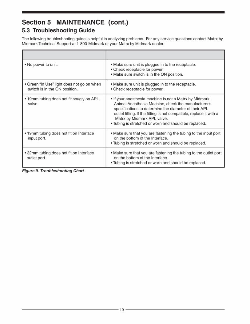
Section 5 MAINTENANCE (cont.)5.3 Troubleshooting GuideThe following troubleshooting guide is helpful in analyzing problems. For any service questions contact Matrx byMidmark Technical Support at 1-800-Midmark or your Matrx by Midmark dealer.
Figure 9. Troubleshooting Chart
SYMPTOM POSSIBLE REMEDIES
• No power to unit. • Make sure unit is plugged in to the receptacle.• Check receptacle for power.• Make sure switch is in the ON position.
• Green “In Use” light does not go on when • Make sure unit is plugged in to the receptacle. switch is in the ON position. • Check receptacle for power.
• 19mm tubing does not fit snugly on APL • If your anesthesia machine is not a Matrx by Midmark valve. Animal Anesthesia Machine, check the manufacturer’s
specifications to determine the diameter of their APL outlet fitting. If the fitting is not compatible, replace it with a Matrx by Midmark APL valve.• Tubing is stretched or worn and should be replaced.
• 19mm tubing does not fit on Interface • Make sure that you are fastening the tubing to the input port input port. on the bottom of the Interface.
• Tubing is stretched or worn and should be replaced.
• 32mm tubing does not fit on Interface • Make sure that you are fastening the tubing to the outlet port outlet port. on the bottom of the Interface.
• Tubing is stretched or worn and should be replaced.

11
Figure 10. Replacement Parts Exploded View
Item Part No. Description Qty.
Interface Kit Components1a 94515143 Interface (domestic) ........................... 11b 94515180 Interface (international) ..................... 1
Gas Disposal Kit Components2 91515140 Set Screw (#8-32 [not shown]) ........ 13 91515141 Inner Wall Plate ................................. 14 91515149 Tube Clamp ....................................... 15 91515150 Screen Stop (not shown) .................. 16 91515164 Screen (not shown) .......................... 17 91515165 Worm Gear Clamp ............................. 18 91515166 Gas Disposal Subassembly ............... 1
Item Part No. Description Qty.
Post Mount Tubing Kit Components9 91515168 Fastener Tube Kit ..............................1
10 65939600 Transfer Tubing, Magenta (19mm) ... 5’11 65939700 Disposal Tubing, Magenta (32mm) 20’
Wall Mount Tubing Kit Components12 91515168 Fastener Tube Kit ..............................113 65939600 Transfer Tubing, Magenta (19mm) . 18’14 65939700 Disposal Tubing, Magenta (32mm) .. 2’
Section 5 MAINTENANCE (cont.)5.4 Replacement PartsThe following illustration shows all available replacement parts for this product. To order replacement parts or forany service questions, contact Matrx by Midmark Technical Support at 1-800-Midmark or your Matrx by Midmarkdealer.
1
8
3
4
7
13 14
9
1110
MX104700i
ON
OFF
2 5 6
12

12
6.1 General Information & 6.2 Return Goods Procedure
Section 6 INFORMATION & WARRANTY
All repairs, unless otherwise specified, should be performed by an authorized Midmark service representative.Call 1-800-MIDMARK (1-800-643-6275) or Customer Service.
6.3 WarrantySCOPE OF WARRANTY Midmark Corporation (“Midmark”) warrants to the original retail purchaser that it will repair orreplace components of the animal health products manufactured by Midmark (except for products and components notwarranted under “Exclusions”) that are defective in material or workmanship under normal use and service. The soleremedy under this limited warranty is the repair or replacement, at Midmark’s option, of the applicable products orcomponents. This limited warranty shall only apply to defects that: (i) are reported to Midmark within the applicablewarranty period; and (ii) are determined to exist upon examination by Midmark. This limited warranty extends only to theoriginal retail purchaser of a product, and is not transferable or assignable.APPLICABLE WARRANTY PERIOD Veterinary Anesthesia Gas Active Scavenger Interface: 1 yearOBTAINING WARRANTY SERVICE Warranty service must be obtained through either Midmark or an authorized dealerin the Midmark product line for which warranty service is requested. Midmark may be contacted for warranty serviceinquiries or issues via email at www.midmark.com, by mail to Midmark Corporation, 60 Vista Drive, Versailles, Ohio45380, or by phone at: 1-800-MIDMARK.It is the retail purchaser’s obligation to arrange for delivery of a product to Midmark or one of its authorized dealers forwarranty service, which delivery shall be at retail purchaser’s expense. It is also the retail purchaser’s obligation tocomply with the warranty service instructions provided either by Midmark or its authorized dealer. The retail purchasermust provide Midmark with completed warranty registration information within thirty (30) days after purchase in order toobtain the benefits of this limited warranty.EXCLUSIONS This limited warranty does not cover and Midmark shall not be liable for the following:(1) defects, damage or other conditions caused, in whole or in part, by misuse, abuse, negligence, alteration, accident(including animal acts of any kind), freight damage, tampering or failure to seek and obtain repair or replacement in atimely manner;(2) matching of color, grain or texture except to commercially acceptable standards;(3) changes in color caused by natural or artificial light;(4) products which are not installed, used and properly cleaned and maintained as required in the installation andoperation manuals for the applicable product (imaging product must be installed by a certified Midmark installer);(5) products considered to be of a consumable nature;(6) accessories or parts not manufactured by Midmark;(7) specially manufactured products;(8) charges by anyone (including Midmark’s authorized dealers) for adjustments, repairs, replacement parts, installationor other work performed upon or in connection with such products which are not expressly authorized in writing inadvance by Midmark;(9) costs and expenses of routine maintenance and cleaning;(10) all sinks, faucets and plumbing accessories;(11) representations and warranties made by any person or entity other than Midmark; and(12) with respect to software that is a product or a component thereof, that the software will be error free, can be usedwithout problems or interruptions, or will be free from vulnerability to intrusion or attack by viruses or other methods.EXCLUSIVE REMEDY; CONSEQUENTIAL DAMAGES DISCLAIMER Midmark’s only obligation under this limitedwarranty is the repair or replacement of defective parts. Midmark shall not be liable for and hereby disclaims any direct,special, indirect, incidental, exemplary or consequential damages or delays including, but not limited to, damages forloss of profits or income, loss of use, downtime, cover, and employee or independent contractor wages, payments andbenefits. This disclaimer shall survive any failure or asserted failure of the essential purpose of this limited warranty or itsremedies specified herein.NO AUTHORIZATION No person or firm is authorized to create or approve for Midmark any other obligation or liability inconnection with Midmark products.WARRANTY DISCLAIMER: THIS LIMITED WARRANTY IS MIDMARK’S ONLY WARRANTY AND IS IN LIEU OF ALLOTHER WARRANTIES, EXPRESS OR IMPLIED. MIDMARK MAKES NO IMPLIED WARRANTIES OF ANY KINDINCLUDING ANY IMPLIED WARRANTIES OF MERCHANTABILITY OR FITNESS FOR A PARTICULAR PURPOSE.STATUTE OF LIMITATIONS No action may be brought against Midmark for breach of this limited warranty, an impliedwarranty, if any, or for any other claim arising out of or relating to the products, more than ninety (90) days followingexpiration of the warranty period. In the event multiple warranty periods exist with respect to a product, the ninety (90)day period provided for herein shall begin to run from expiration of the warranty period for the component to which theclaim relates.SEVERABILITY In the event any provision of this limited warranty is determined to be invalid or otherwise unenforceable:(i) the provision shall be enforced in a manner that closest holds to its intent, while at the same time curing the invalidityor unenforceability, and (ii) the balance of this limited warranty, being severable, shall not be affected in the event theprovision that is invalid or unenforceable cannot be enforced in any respect.


iv
Notes and Contact Information
_________________________________________ ___________________________________________Unit Serial Number Date Purchased
_________________________________________ ___________________________________________Dealer Name Dealer Phone Number
Notes:
Contact Information:
1-800-Midmark (643-6275)www.midmark.com
![Veterinary Anesthesia [Autosaved]](https://static.fdocuments.us/doc/165x107/55cf917a550346f57b8dbe92/veterinary-anesthesia-autosaved.jpg)