
(VERTICALMOUNT) Transmission 18000 Series HMD · COMPONENT TECHNICAL MANUAL 18000 HMD Transmission...
146
COMPONENT TECHNICAL MANUAL 18000 HMD Transmission CTM158 18MAR09 (ENGLISH) 18000 Series HMD Transmission (VERTICAL MOUNT) John Deere Coffeyville Works LITHO IN U.S.A.
Transcript of (VERTICALMOUNT) Transmission 18000 Series HMD · COMPONENT TECHNICAL MANUAL 18000 HMD Transmission...

COMPONENT TECHNICAL MANUAL18000 HMD TransmissionCTM158 18MAR09 (ENGLISH)
18000 Series HMDTransmission
(VERTICAL MOUNT)
John Deere Coffeyville WorksLITHO IN U.S.A.

Introduction
YZ01324,0000007 1913MAR091/1
ForewordThis manual is written for an experienced technician.It contains safety information; recommended torquevalues; lubricant and coolant recommendations; theoryof operation information; Disassembly and Assemblyprocedures; illustrations; other specifications andinstructions necessary to service the transmission. Usethis component technical manual in conjunction with themachine technical manual.
Live With Safety: Read the safety messages in theSafety Group of this manual and the Cautions presentedthroughout the text in this manual.
This is the safetyalert symbol. When you see thissymbol on the machine or in this manual, be alert to thepotential for personal injury.
Fundamental service information is available from othersources covering basic theory of operation, fundamentalsof troubleshooting, general maintenance, and basic typesof failures and their causes.
All information, illustrations, and specifications in thismanual are based on the latest product information
available at the time of production. The right is reservedto make changes at any time without notice.
References to assist technician during machine diagnosisand repair.• Transmission Identification List• General Repair List• Torque Values List• Lubricants and Coolants List• Sealants and Adhesives List• Restoration and Preservation List• Gasket and Anaerobic Sealant Application List• Tools and Other Materials List• Repair Specifications List• K Series Transmission List• Repair and Adjustments List• Transmission Operation List• Brake Operation List• Hydraulic Shifter Operation List• Troubleshooting List• DEALER FABRICATED TOOLS LIST
CTM158 (18MAR09) 18000 HMD Transmission031809
PN=2

Contents
Section 10—General InformationGroup 05—SafetyGroup 10—Transmission IdentificationGroup 15—General RepairGroup 20—Torque ValuesGroup 25—Lubricants and CoolantsGroup 30—Sealants and AdhesivesGroup 35—Restoration and PreservationGroup 40—Gasket/Anaerobic Sealant Application
Section 50—HMD TransmissionGroup 05—Tools and Other MaterialsGroup 10—Repair SpecificationsGroup 11—K Series TransmissionGroup 15—Repair and AdjustmentsGroup 20—Transmission OperationGroup 25—Brake OperationGroup 30—Hydraulic Shifter OperationGroup 35—Troubleshooting
Section 99—SPECIAL TOOLS (DealerFabricated)
Group 10—DEALERFABRICATED TOOLS
All information, illustrations and specifications in this manual are basedon the latest information available at the time of publication. The right is
reserved to make changes at any time without notice.COPYRIGHT © 2009DEERE & COMPANY
Moline, IllinoisAll rights reserved.
A John Deere ILLUSTRUCTION ® ManualPrevious Editions
Copyright © 2003, 2005
CTM158 (18MAR09) i 18000 HMD Transmission031809
PN=1

Contents
CTM158 (18MAR09) ii 18000 HMD Transmission031809
PN=2

Section 10General Information
Contents
Page
Group 05—Safety ......................................1005 1
Group 10—Transmission IdentificationTransmission Identification List ................... 1010 1Standard Model ........................................... 1010 1Standard Model With Options...................... 1010 2Identification And Serial NumberPlates....................................................... 1010 3
18000 Model Code Designation .................. 1010 4Gear Ratio Chart ......................................... 1010 4
Group 15—General RepairGeneral Repair List...................................... 1015 1General Repair Procedures......................... 1015 1
Group 20—Torque ValuesTorque Values List ....................................... 1020 1Unified Inch Bolt and Screw TorqueValues...................................................... 1020 1
Metric Bolt and Screw TorqueValues...................................................... 1020 2
Suggested Wrenching Torque ForTapered Pipe Thread ............................... 1020 3
Group 25—Lubricants and CoolantsLubricants and Coolants List ....................... 1025 1Transmission and Hydraulic Oil ................... 1025 1Mixing of Lubricants..................................... 1025 1Cold Weather Operation.............................. 1025 2Fill The Transmission With Oil ..................... 1025 2Check And Service TransmissionRegularly ................................................. 1025 2
Group 30—Sealants and AdhesivesSealants and Adhesives List ....................... 1030 1Sealants and AdhesivesCrossReference Chart............................ 1030 1
Group 35—Restoration and PreservationRestoration and Preservation List................ 1035 1Restoring Transmission FromStorage .................................................... 1035 1
Preserving Transmission ForStorage .................................................... 1035 1
Group 40—Gasket/Anaerobic Sealant ApplicationGasket and Anaerobic SealantApplication List ........................................ 1040 1
Clean Surfaces............................................ 1040 1Apply Gasket Sealant .................................. 1040 1
CTM158 (18MAR09) 101 18000 HMD Transmission031809
PN=1

Contents
CTM158 (18MAR09) 102 18000 HMD Transmission031809
PN=2

Group 05Safety
YZ01324,0000006 1927AUG021/1
DX,ALERT 1929SEP981/1
Vehicle Runaway TagThis tag is attached to each unit when it is shipped.Please heed warning!
YZ2178—UN—31MAY
00
Recognize Safety InformationThis is a safetyalert symbol. When you see this symbolon your machine or in this manual, be alert to the potentialfor personal injury.
Follow recommended precautions and safe operatingpractices.
T81389
—UN—07DEC88
CTM158 (18MAR09) 10051 18000 HMD Transmission031809
PN=7

Safety
DX,SIGNAL 1903MAR931/1
DX,READ 1903MAR931/1
DX,AIR 1917FEB991/1
Understand Signal WordsA signal word—DANGER, WARNING, or CAUTION—isused with the safetyalert symbol. DANGER identifies themost serious hazards.
DANGER or WARNING safety signs are located nearspecific hazards. General precautions are listed onCAUTION safety signs. CAUTION also calls attention tosafety messages in this manual.
TS187—19—30SEP88
Follow Safety InstructionsCarefully read all safety messages in this manual and onyour machine safety signs. Keep safety signs in goodcondition. Replace missing or damaged safety signs. Besure new equipment components and repair parts includethe current safety signs. Replacement safety signs areavailable from your John Deere dealer.
Learn how to operate the machine and how to use controlsproperly. Do not let anyone operate without instruction.
Keep your machine in proper working condition.Unauthorized modifications to the machine may impair thefunction and/or safety and affect machine life.
If you do not understand any part of this manual and needassistance, contact your John Deere dealer.
TS201—UN—23AUG88
Work In Ventilated AreaEngine exhaust fumes can cause sickness or death. Ifit is necessary to run an engine in an enclosed area,remove the exhaust fumes from the area with an exhaustpipe extension.
If you do not have an exhaust pipe extension, open thedoors and get outside air into the area.
TS220—UN—23AUG88
CTM158 (18MAR09) 10052 18000 HMD Transmission031809
PN=8

Safety
DX,CLEAN 1904JUN901/1
DX,DRAIN 1903MAR931/1
DX,FIRE2 1903MAR931/1
Work in Clean AreaBefore starting a job:
• Clean work area and machine.• Make sure you have all necessary tools to do your job.• Have the right parts on hand.• Read all instructions thoroughly; do not attemptshortcuts.
T6642E
J—UN—18OCT88
Dispose of Waste ProperlyImproperly disposing of waste can threaten theenvironment and ecology. Potentially harmful waste usedwith John Deere equipment include such items as oil, fuel,coolant, brake fluid, filters, and batteries.
Use leakproof containers when draining fluids. Do not usefood or beverage containers that may mislead someoneinto drinking from them.
Do not pour waste onto the ground, down a drain, or intoany water source.
Air conditioning refrigerants escaping into the air candamage the Earth’s atmosphere. Government regulationsmay require a certified air conditioning service center torecover and recycle used air conditioning refrigerants.
Inquire on the proper way to recycle or dispose of wastefrom your local environmental or recycling center, or fromyour John Deere dealer.
TS1133
—UN—26NOV90
Prepare for EmergenciesBe prepared if a fire starts.
Keep a first aid kit and fire extinguisher handy.
Keep emergency numbers for doctors, ambulanceservice, hospital, and fire department near your telephone.
TS291—UN—23AUG88
CTM158 (18MAR09) 10053 18000 HMD Transmission031809
PN=9

Safety
DX,CABS2 1924JUL011/1
DX,CABS1 1903MAR931/1
Clean Vehicle of Hazardous Pesticides
CAUTION: During application of hazardouspesticides, pesticide residue can build upon the inside or outside of the vehicle.Clean vehicle according to use instructionsof hazardous pesticides.
When exposed to hazardous pesticides, clean exterior andinterior of vehicle daily to keep free of the accumulation ofvisible dirt and contamination.
1. Sweep or vacuum the floor of cab.
2. Clean headliners and inside cowlings of cab.
3. Wash entire exterior of vehicle.
4. Dispose of any wash water with hazardousconcentrations of active or nonactive ingredientsaccording to published regulations or directives.
Avoid Contact with Pesticides
CAUTION: This enclosed cab does not protectagainst inhaling harmful pesticides.
1. When operating in an environment where harmfulpesticides are present, wear a longsleeved shirt,longlegged pants, shoes, and socks.
2. If pesticide use instructions require respiratoryprotection, wear an appropriate respirator inside thecab.
3. Wear personal protective equipment as requiredby the pesticide use instructions when leaving theenclosed cab:
• into a treated area,• to work with contaminated application equipmentsuch as nozzles which must be cleaned, changed,or redirected.• to become involved with mixing and loadingactivities.
4. Before reentering the cab, remove protectiveequipment and store either outside the cab in a closedbox or some other type of sealable container or insidethe cab in a pesticide resistant container, such as aplastic bag.
5. Clean your shoes or boots to remove soil or othercontaminated particles prior to entering the cab.
TS220—UN—23AUG88
TS272—UN—23AUG88
CTM158 (18MAR09) 10054 18000 HMD Transmission031809
PN=10

Safety
DX,DUST 1915MAR911/1
DX,FLAME 1929SEP981/1
DX,FLUID 1903MAR931/1
Avoid Harmful Asbestos DustAvoid breathing dust that may be generated whenhandling components containing asbestos fibers. Inhaledasbestos fibers may cause lung cancer.
Components in products that may contain asbestosfibers are brake pads, brake band and lining assemblies,clutch plates, and some gaskets. The asbestos used inthese components is usually found in a resin or sealed insome way. Normal handling is not hazardous as long asairborne dust containing asbestos is not generated.
Avoid creating dust. Never use compressed air forcleaning. Avoid brushing or grinding material containingasbestos. When servicing, wear an approved respirator.A special vacuum cleaner is recommended to cleanasbestos. If not available, apply a mist of oil or water onthe material containing asbestos.
TS220—UN—23AUG88
Keep bystanders away from the area.
Handle Fluids Safely—Avoid FiresWhen you work around fuel, do not smoke or work nearheaters or other fire hazards.
Store flammable fluids away from fire hazards. Do notincinerate or puncture pressurized containers.
Make sure machine is clean of trash, grease, and debris.
Do not store oily rags; they can ignite and burnspontaneously.
TS227—UN—23AUG88
Avoid HighPressure FluidsEscaping fluid under pressure can penetrate the skincausing serious injury.
Avoid the hazard by relieving pressure beforedisconnecting hydraulic or other lines. Tighten allconnections before applying pressure.
Search for leaks with a piece of cardboard. Protect handsand body from high pressure fluids.
If an accident occurs, see a doctor immediately. Any fluidinjected into the skin must be surgically removed withina few hours or gangrene may result. Doctors unfamiliarwith this type of injury should reference a knowledgeablemedical source. Such information is available from Deere& Company Medical Department in Moline, Illinois, U.S.A.
X9811
—UN—23AUG88
CTM158 (18MAR09) 10055 18000 HMD Transmission031809
PN=11

Safety
DX,POISON 1921APR931/1
DX,LIFT 1904JUN901/1
Prevent Acid BurnsSulfuric acid in battery electrolyte is poisonous. It is strongenough to burn skin, eat holes in clothing, and causeblindness if splashed into eyes.
Avoid the hazard by:
1. Filling batteries in a wellventilated area.2. Wearing eye protection and rubber gloves.3. Avoiding breathing fumes when electrolyte is added.4. Avoiding spilling or dripping electrolyte.5. Use proper jump start procedure.
If you spill acid on yourself:
1. Flush your skin with water.2. Apply baking soda or lime to help neutralize the acid.3. Flush your eyes with water for 15—30 minutes. Get
medical attention immediately.
If acid is swallowed:
1. Do not induce vomiting.2. Drink large amounts of water or milk, but do not
exceed 2 L (2 quarts).3. Get medical attention immediately.
TS203—UN—23AUG88
Use Proper Lifting EquipmentLifting heavy components incorrectly can cause severeinjury or machine damage.
Follow recommended procedure for removal andinstallation of components in the manual.
TS226—UN—23AUG88
CTM158 (18MAR09) 10056 18000 HMD Transmission031809
PN=12

Safety
DX,LIGHT 1904JUN901/1
DX,LIVE 1925SEP921/1
DX,LOOSE 1904JUN901/1
Illuminate Work Area SafelyIlluminate your work area adequately but safely. Usea portable safety light for working inside or under themachine. Make sure the bulb is enclosed by a wire cage.The hot filament of an accidentally broken bulb can ignitespilled fuel or oil.
TS223—UN—23AUG88
Live With SafetyBefore returning machine to customer, make suremachine is functioning properly, especially the safetysystems. Install all guards and shields.
TS231—19—07OCT88
Service Machines SafelyTie long hair behind your head. Do not wear a necktie,scarf, loose clothing, or necklace when you work nearmachine tools or moving parts. If these items were to getcaught, severe injury could result.
Remove rings and other jewelry to prevent electricalshorts and entanglement in moving parts.
TS228—UN—23AUG88
CTM158 (18MAR09) 10057 18000 HMD Transmission031809
PN=13

Safety
DX,LOWER 1924FEB001/1
DX,PAINT 1924JUL021/1
DX,PARK 1904JUN901/1
Support Machine ProperlyAlways lower the attachment or implement to the groundbefore you work on the machine. If the work requiresthat the machine or attachment be lifted, provide securesupport for them. If left in a raised position, hydraulicallysupported devices can settle or leak down.
Do not support the machine on cinder blocks, hollow tiles,or props that may crumble under continuous load. Do notwork under a machine that is supported solely by a jack.Follow recommended procedures in this manual.
When implements or attachments are used with amachine, always follow safety precautions listed in theimplement or attachment operator’s manual.
TS229—UN—23AUG88
Remove Paint Before Welding or HeatingAvoid potentially toxic fumes and dust.
Hazardous fumes can be generated when paint is heatedby welding, soldering, or using a torch.
Remove paint before heating:
• Remove paint a minimum of 100 mm (4 in.) from areato be affected by heating. If paint cannot be removed,wear an approved respirator before heating or welding.• If you sand or grind paint, avoid breathing the dust.Wear an approved respirator.• If you use solvent or paint stripper, remove stripper withsoap and water before welding. Remove solvent orpaint stripper containers and other flammable materialfrom area. Allow fumes to disperse at least 15 minutesbefore welding or heating.
Do not use a chlorinated solvent in areas where weldingwill take place.
TS220—UN—23AUG88
Do all work in an area that is well ventilated to carry toxicfumes and dust away.
Dispose of paint and solvent properly.
Park Machine SafelyBefore working on the machine:
• Lower all equipment to the ground.• Stop the engine and remove the key.• Disconnect the battery ground strap.• Hang a "DO NOT OPERATE" tag in operator station.
TS230—UN—24MAY
89
CTM158 (18MAR09) 10058 18000 HMD Transmission031809
PN=14

Safety
DX,REPAIR 1917FEB991/1
DX,SAFE,TOOLS 1910OCT971/1
DX,SIGNS1 1904JUN901/1
Use Proper ToolsUse tools appropriate to the work. Makeshift tools andprocedures can create safety hazards.
Use power tools only to loosen threaded parts andfasteners.
For loosening and tightening hardware, use the correctsize tools. DO NOT use U.S. measurement tools onmetric fasteners. Avoid bodily injury caused by slippingwrenches.
Use only service parts meeting John Deere specifications. TS779—UN—08NOV89
Construct DealerMade Tools SafelyFaulty or broken tools can result in serious injury. Whenconstructing tools, use proper, quality materials, and goodworkmanship.
Do not weld tools unless you have the proper equipmentand experience to perform the job.
LX1016749—UN—01JU
L97
Replace Safety SignsReplace missing or damaged safety signs. See themachine operator’s manual for correct safety signplacement.
TS201—UN—23AUG88
CTM158 (18MAR09) 10059 18000 HMD Transmission031809
PN=15

Safety
DX,TORCH 1910DEC041/1
DX,WEAR 1910SEP901/1
DX,BYPAS1 1929SEP981/1
Avoid Heating Near Pressurized Fluid LinesFlammable spray can be generated by heating nearpressurized fluid lines, resulting in severe burns to yourselfand bystanders. Do not heat by welding, soldering,or using a torch near pressurized fluid lines or otherflammable materials. Pressurized lines can accidentallyburst when heat goes beyond the immediate flame area.
TS953—UN—15MAY
90
Wear Protective ClothingWear close fitting clothing and safety equipmentappropriate to the job.
Prolonged exposure to loud noise can cause impairmentor loss of hearing.
Wear a suitable hearing protective device such asearmuffs or earplugs to protect against objectionable oruncomfortable loud noises.
Operating equipment safely requires the full attention ofthe operator. Do not wear radio or music headphoneswhile operating machine.
TS206—UN—23AUG88
Prevent Machine RunawayAvoid possible injury or death from machinery runaway.
Do not start engine by shorting across starter terminals.Machine will start in gear if normal circuitry is bypassed.
NEVER start engine while standing on ground. Startengine only from operator’s seat, with transmission inneutral or park.
TS177—UN—11JAN89
CTM158 (18MAR09) 100510 18000 HMD Transmission031809
PN=16

Safety
DX,MSDS,NA 1903MAR931/1
DX,NOISE 1903MAR931/1
DX,PTO 1912SEP951/1
Handle Chemical Products SafelyDirect exposure to hazardous chemicals can causeserious injury. Potentially hazardous chemicals used withJohn Deere equipment include such items as lubricants,coolants, paints, and adhesives.
A Material Safety Data Sheet (MSDS) provides specificdetails on chemical products: physical and health hazards,safety procedures, and emergency response techniques.
Check the MSDS before you start any job using ahazardous chemical. That way you will know exactly whatthe risks are and how to do the job safely. Then followprocedures and recommended equipment.
(See your John Deere dealer for MSDS’s on chemicalproducts used with John Deere equipment.)
TS1132
—UN—26NOV90
Protect Against NoiseProlonged exposure to loud noise can cause impairmentor loss of hearing.
Wear a suitable hearing protective device such asearmuffs or earplugs to protect against objectionable oruncomfortable loud noises.
TS207—UN—23AUG88
Stay Clear of Rotating DrivelinesEntanglement in rotating driveline can cause seriousinjury or death.
Keep tractor master shield and driveline shields in placeat all times. Make sure rotating shields turn freely.
Wear close fitting clothing. Stop the engine and be surePTO driveline is stopped before making adjustments,connections, or cleaning out PTO driven equipment.
TS1644
—UN—22AUG95
CTM158 (18MAR09) 100511 18000 HMD Transmission031809
PN=17

Safety
DX,SERV 1917FEB991/1
Practice Safe MaintenanceUnderstand service procedure before doing work. Keeparea clean and dry.
Never lubricate, service, or adjust machine while it ismoving. Keep hands, feet , and clothing from powerdrivenparts. Disengage all power and operate controls to relievepressure. Lower equipment to the ground. Stop theengine. Remove the key. Allow machine to cool.
Securely support any machine elements that must beraised for service work.
Keep all parts in good condition and properly installed.Fix damage immediately. Replace worn or broken parts.Remove any buildup of grease, oil, or debris.
On selfpropelled equipment, disconnect battery groundcable () before making adjustments on electrical systemsor welding on machine.
On towed implements, disconnect wiring harnesses fromtractor before servicing electrical system components orwelding on machine.
TS218—UN—23AUG88
CTM158 (18MAR09) 100512 18000 HMD Transmission031809
PN=18
Safety
DX,RIM 1924AUG901/1
DX,ROPS1 1929OCT071/1
DPSG,YZ01324,190 1911APR001/1
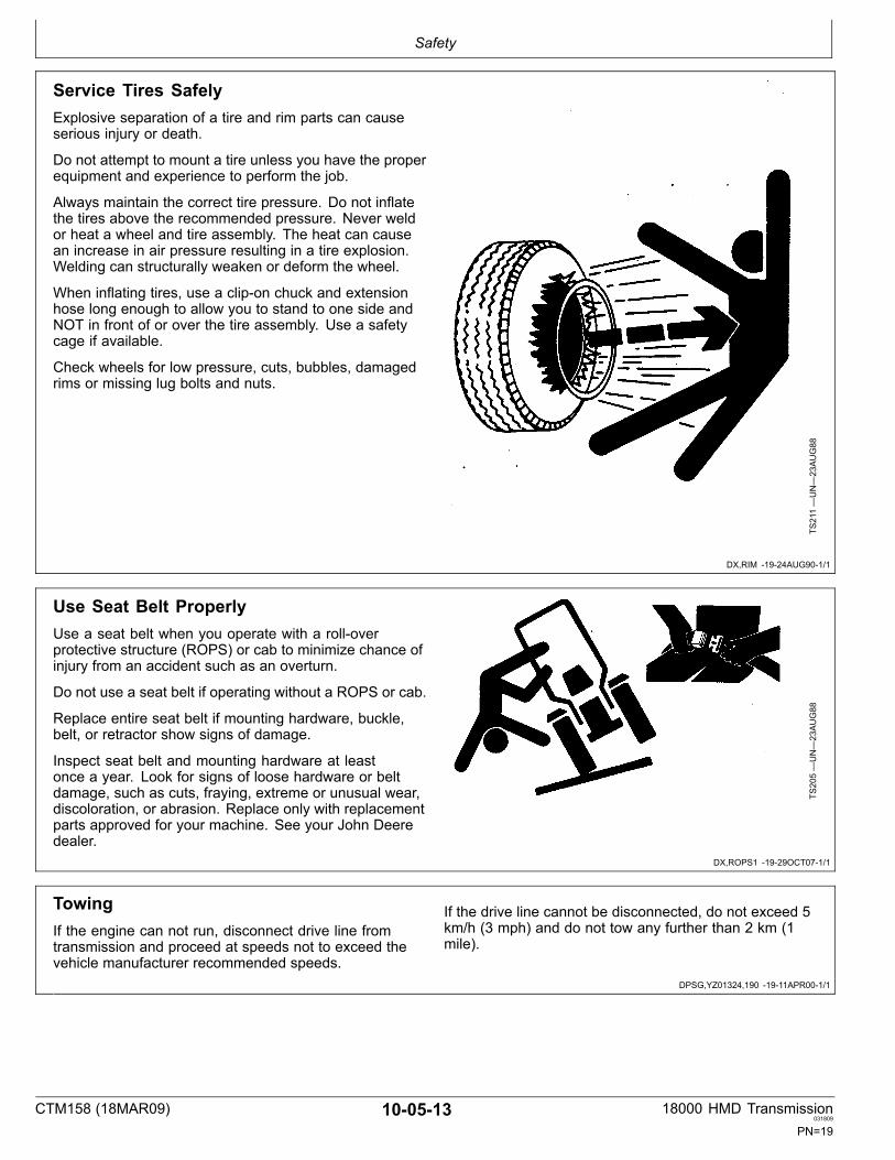
Service Tires SafelyExplosive separation of a tire and rim parts can causeserious injury or death.
Do not attempt to mount a tire unless you have the properequipment and experience to perform the job.
Always maintain the correct tire pressure. Do not inflatethe tires above the recommended pressure. Never weldor heat a wheel and tire assembly. The heat can causean increase in air pressure resulting in a tire explosion.Welding can structurally weaken or deform the wheel.
When inflating tires, use a clipon chuck and extensionhose long enough to allow you to stand to one side andNOT in front of or over the tire assembly. Use a safetycage if available.
Check wheels for low pressure, cuts, bubbles, damagedrims or missing lug bolts and nuts.
TS211—UN—23AUG88
Use Seat Belt ProperlyUse a seat belt when you operate with a rolloverprotective structure (ROPS) or cab to minimize chance ofinjury from an accident such as an overturn.
Do not use a seat belt if operating without a ROPS or cab.
Replace entire seat belt if mounting hardware, buckle,belt, or retractor show signs of damage.
Inspect seat belt and mounting hardware at leastonce a year. Look for signs of loose hardware or beltdamage, such as cuts, fraying, extreme or unusual wear,discoloration, or abrasion. Replace only with replacementparts approved for your machine. See your John Deeredealer.
TS205—UN—23AUG88
TowingIf the engine can not run, disconnect drive line fromtransmission and proceed at speeds not to exceed thevehicle manufacturer recommended speeds.
If the drive line cannot be disconnected, do not exceed 5km/h (3 mph) and do not tow any further than 2 km (1mile).
CTM158 (18MAR09) 100513 18000 HMD Transmission031809
PN=19

Safety
CTM158 (18MAR09) 100514 18000 HMD Transmission031809
PN=20

Group 10Transmission Identification
YZ07927,0000027 1927FEB091/1
DPSG,YZ01324,85 1913MAR091/1
Transmission Identification ListReferences to assist technician during machine diagnosisand repair.
• Standard Model
• Standard Model With Options• Identification And Serial Number Plates• 18000 Model Code Designation• Gear Ratio Chart
Standard Model
YZ2314—UN—07MAY
03
Standard Model
A—Hydraulic Motor Adapter1B—Bearing RetainerC—Shifter Shaft
D—Yoke and Companion FlangeGroup2
E—Input HousingF—Output Housing
G—DipstickH—Lube Pump GroupI— Breather (7/16 psi)
J— Identification PlateK—Magnetic Plug (3/4 NPT)
1SAE “D” is the standard. SAE “B” and “C” adapters areoptions. SAE “D” is shown.25C, 6C, 7C Yoke, or Companion Flanges are options.
CTM158 (18MAR09) 10101 18000 HMD Transmission031809
PN=21

Transmission Identification
YZ01324,000003C 1913MAR091/1
Standard Model With Options
YZ2314A
—UN—11JU
N03
Standard Model With Hydraulic Shifter and Disc Brake Options
A—Hydraulic Motor Adapter1B—Bearing RetainerC—Hydraulic Shifter (Option)D—Yoke and Companion Flange
Group2
E—Input HousingF—Output HousingG—DipstickH—Lube Pump Group
I— Breather (7/16 psi)3J— Identification PlateK—Magnetic Plug (3/4 NPT)L—Disc Brake (Option)
M—Disc Brake Caliper Assembly(Option)
1SAE “D” is the standard. SAE “B” and “C” adapters areoptions. SAE “C” is shown.25C, 6C, 7C Yoke, or Companion Flanges are options.3Alternate location.
CTM158 (18MAR09) 10102 18000 HMD Transmission031809
PN=22

Transmission Identification
DPSG,YZ01324,183 1913MAR091/2
DPSG,YZ01324,183 1913MAR092/2
Identification And Serial Number PlatesThe identification plate is located on the motor side ofthe transmission on the input housing, just below theoutput. The model number identifies the product family.The spec number is used to identify the transmissionand generate a bill of materials. The serial number andequipment number are used to track the transmissionassembled date and shipment date, as well as, identifyingthe customer. All information on the identification plate isneeded when contacting the supplier.
YZ1502—UN—24APR98
Record the information from the plate on your transmissionfor future references and have available when contactingyour supplier or John Deere Dealers.
Contact:
• John Deere Coffeyville Works• 2624 Hwy 169• Coffeyville, KS 673370577• Telephone: (800) 8441337 or (620)2513400• Fax: (620) 25234253
YZ6850—UN—20SEP07
CTM158 (18MAR09) 10103 18000 HMD Transmission031809
PN=23

Transmission Identification
YZ07927,0000025 1913MAR091/1
YZ07927,0000026 1913MAR091/1
18000 Model Code Designation18000 MODEL CODE DESIGNATION
18 D V XXX A
A
SERIES DESIGANTIONL
UNIT MOUNTING POSITION (VERTICAL)J
GEAR RATIO GROUPI
GEAR RATIO LOWH
GEAR RATIO HIG
BRAKE TYPE, LOCATION, & POSITIONF
OUTPUT FTG MOTOR SIDEE
OUTPUT FTG OPP MTRD
SPECIAL DESCRIPTIONC
DESIGNB
SAE MOTOR SIZE (SAE “D, B, OR C”)K
X X X X X X
YZ9190—UN—05FE
B09
A—18000 Model CodeDesignation
B—Design Description (A)1C—Special Unit Description
(X,H)2
D—Output Fitting Opposite MotorSide (F,5,6,7)3
E—Output Fitting Motor Side(F,5,6,7)4
F—Brake Type, Location, andPosition (D,O,8,4,P)5
G—Gear Ratio Hi (A or B)H—Gear Ratio Low (1, 2 or 3)I— Gear Ratio Group (A or B)
J—Unit Mounting Position (V =Vertical)
K—SAE Motor Size (SAE B, C, orD)
L—Series Designation
1Production Release2X = Standard (Mechanical), H = Hydraulic Shift.3Same as H.4F = Companion Flange, 5 = Mechanical Flange, 6 = MechanicalFlange, 7 = Mechanical Flange.5D = Disk 14” 3/4 Opposite Motor Side, O = Opposite Motor Side,8 = 8 O’clock, 4=4:00 O’clock, P = Pawl.
Gear Ratio ChartNOTE: Select Ratio Group “A” or “B”, Select Low and
High Ratio from Ratio group, Example: A12 =(Group “A”, 2.569:1 Low, 1.613:1 High)
18000 Ratio Selection ChartRange Ratio Group “A” Ratio Group “B”Low 1. — 2.569 4.599Low 2. — 4.140 7.412Low 3. — 5.487 9.823High 1. — 1.613 1.905
CTM158 (18MAR09) 10104 18000 HMD Transmission031809
PN=24

Group 15General Repair
YZ07927,0000028 1927FEB091/1
YZ01324,00000E5 1913MAR091/1
General Repair ListReferences to assist technician during machine diagnosisand repair.
• General Repair Procedures
General Repair Procedures
NOTE: Before beginning the repair, review the followingguidelines. Gulidelines are provided to emphasizethe need for attention to detail and care whenservicing the Transmission assembly.
Thoroughly clean the outside before disassembly.
Handle parts carefully to prevent nicking or burringmachined surfaces.
Inspection Before Disassembly.
Inspect the gears, shafts, and bearing before removal asfollows:
1. Wipe the lubricant from the internal working partsand visually inspect the parts for excessive wear ordamage.
2. Inspect the gears for roughness.
3. Inspect the gear teeth for signs of scoring, abnormalwear, nicks, or chips.
Cleaning and Inspection
Clean all parts with clean solvent and use moisturefreeair for drying.
Bearings
Never dry bearings with compressed air. Spinning abearing without lubrication can damage the bearing.
Clean bearings with clean solvent, dry thoroughly, andoil before inspection. Inspect bearings for roughness ofrotation and excessive wear of rollers.
Inspect bearing cups for excessive wear.
Both the bearing cone and roller assembly must bereplaced if either the cup or cone has excessive wear.
Inspect tapered bearings and roller bearing surfaces fordistortion, roughness, scoring, or wear.
When installing bearing cups and cones, make sure theyare fully seated.
Cups and cones are properly seated if a 0.05 mm (0.002in.) feeler gauge will NOT pass for a 360° circular sweepbetween cone or cup mounting surface.
Shafts
Inspect the shaft bearing surfaces for wear or damage.
Inspect shafts and replace if excessively worn ordamaged.
Gear Assemblies
Examine the gear teeth for excessive wear. Replace asnecessary.
Fasteners and Tightening
Fasteners must be tightened to the specified torque.
Fasteners must be replaced with the same property class(grade).
Follow the specified tightening pattern when listed.
Clean all threaded fasteners with cleaning solvent. Dryand apply Loctite® 7649 (PM37509) Primer and Loctite®262 to threads.
Apply pipe thread sealer with teflon® (PM38613) to allpipe thread fittings.
Different models of transmission and Early VersionTransmissions have a different torque specification andfastener than Later Version Transmissions. Check themodel number and or the fastener removed and use thecorrect torque specification and fastener.
Assembly
Use the specified grease when installing seals.
During assembly, each part must be lubricated with cleanhydraulic oil.
CTM158 (18MAR09) 10151 18000 HMD Transmission031809
PN=25

General Repair
CTM158 (18MAR09) 10152 18000 HMD Transmission031809
PN=26
Group 20Torque Values
YZ07927,0000029 1927FEB091/1
DX,TORQ1 1924APR031/1
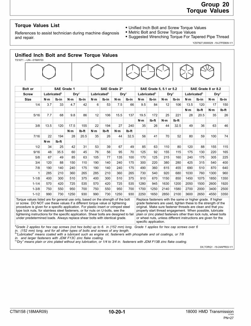
Torque Values ListReferences to assist technician during machine diagnosisand repair.
• Unified Inch Bolt and Screw Torque Values• Metric Bolt and Screw Torque Values• Suggested Wrenching Torque For Tapered Pipe Thread
Unified Inch Bolt and Screw Torque ValuesTS1671 —UN—01MAY03
Bolt or SAE Grade 1 SAE Grade 2a SAE Grade 5, 5.1 or 5.2 SAE Grade 8 or 8.2Screw Lubricatedb Dryc Lubricatedb Dryc Lubricatedb Dryc Lubricatedb Dryc
Size N∙m lbin N∙m lbin N∙m lbin N∙m lbin N∙m lbin N∙m lbin N∙m lbin N∙m lbin1/4 3.7 33 4.7 42 6 53 7.5 66 9.5 84 12 106 13.5 120 17 150
N∙m lbft N∙m lbft5/16 7.7 68 9.8 86 12 106 15.5 137 19.5 172 25 221 28 20.5 35 26
N∙m lbft N∙m lbft3/8 13.5 120 17.5 155 22 194 27 240 35 26 44 32.5 49 36 63 46
N∙m lbft N∙m lbft N∙m lbft7/16 22 194 28 20.5 35 26 44 32.5 56 41 70 52 80 59 100 74
N∙m lbft1/2 34 25 42 31 53 39 67 49 85 63 110 80 120 88 155 1159/16 48 35.5 60 45 76 56 95 70 125 92 155 115 175 130 220 1655/8 67 49 85 63 105 77 135 100 170 125 215 160 240 175 305 2253/4 120 88 150 110 190 140 240 175 300 220 380 280 425 315 540 4007/8 190 140 240 175 190 140 240 175 490 360 615 455 690 510 870 6401 285 210 360 265 285 210 360 265 730 540 920 680 1030 760 1300 960
11/8 400 300 510 375 400 300 510 375 910 670 1150 850 1450 1075 1850 135011/4 570 420 725 535 570 420 725 535 1280 945 1630 1200 2050 1500 2600 192013/8 750 550 950 700 750 550 950 700 1700 1250 2140 1580 2700 2000 3400 250011/2 990 730 1250 930 990 730 1250 930 2250 1650 2850 2100 3600 2650 4550 3350
Torque values listed are for general use only, based on the strength of the boltor screw. DO NOT use these values if a different torque value or tighteningprocedure is given for a specific application. For plastic insert or crimped steeltype lock nuts, for stainless steel fasteners, or for nuts on Ubolts, see thetightening instructions for the specific application. Shear bolts are designed to failunder predetermined loads. Always replace shear bolts with identical grade.
Replace fasteners with the same or higher grade. If highergrade fasteners are used, tighten these to the strength of theoriginal. Make sure fastener threads are clean and that youproperly start thread engagement. When possible, lubricateplain or zinc plated fasteners other than lock nuts, wheel boltsor wheel nuts, unless different instructions are given for thespecific application.
aGrade 2 applies for hex cap screws (not hex bolts) up to 6. in (152 mm) long. Grade 1 applies for hex cap screws over 6in. (152 mm) long, and for all other types of bolts and screws of any length.b“Lubricated” means coated with a lubricant such as engine oil, fasteners with phosphate and oil coatings, or 7/8in. and larger fasteners with JDM F13C zinc flake coating.c“Dry” means plain or zinc plated without any lubrication, or 1/4 to 3/4 in. fasteners with JDM F13B zinc flake coating.
CTM158 (18MAR09) 10201 18000 HMD Transmission031809
PN=27

Torque Values
DX,TORQ2 1924APR031/1
Metric Bolt and Screw Torque ValuesTS1670 —UN—01MAY03
4.84.8 8.8 9.8 10.9 12.9 12.9
12.912.910.99.88.84.8
Bolt or Class 4.8 Class 8.8 or 9.8 Class 10.9 Class 12.9Screw Lubricateda Dryb Lubricateda Dryb Lubricateda Dryb Lubricateda Dryb
Size N∙m lbin N∙m lbin N∙m lbin N∙m lbin N∙m lbin N∙m lbin N∙m lbin N∙m lbinM6 4.7 42 6 53 8.9 79 11.3 100 13 115 16.5 146 15.5 137 19.5 172
N∙m lbft N∙m lbft N∙m lbft N∙m lbftM8 11.5 102 14.5 128 22 194 27.5 243 32 23.5 40 29.5 37 27.5 47 35
N∙m lbft N∙m lbft N∙m lbftM10 23 204 29 21 43 32 55 40 63 46 80 59 75 55 95 70
N∙m lbftM12 40 29.5 50 37 75 55 95 70 110 80 140 105 130 95 165 120M14 63 46 80 59 120 88 150 110 175 130 220 165 205 150 260 190M16 100 74 125 92 190 140 240 175 275 200 350 255 320 235 400 300M18 135 100 170 125 265 195 330 245 375 275 475 350 440 325 560 410M20 190 140 245 180 375 275 475 350 530 390 675 500 625 460 790 580M22 265 195 330 245 510 375 650 480 725 535 920 680 850 625 1080 800M24 330 245 425 315 650 480 820 600 920 680 1150 850 1080 800 1350 1000M27 490 360 625 460 950 700 1200 885 1350 1000 1700 1250 1580 1160 2000 1475M30 660 490 850 625 1290 950 1630 1200 1850 1350 2300 1700 2140 1580 2700 2000M33 900 665 1150 850 1750 1300 2200 1625 2500 1850 3150 2325 2900 2150 3700 2730M36 1150 850 1450 1075 2250 1650 2850 2100 3200 2350 4050 3000 3750 2770 4750 3500
Torque values listed are for general use only, based on the strength ofthe bolt or screw. DO NOT use these values if a different torque value ortightening procedure is given for a specific application. For stainless steelfasteners or for nuts on Ubolts, see the tightening instructions for thespecific application. Tighten plastic insert or crimped steel type lock nutsby turning the nut to the dry torque shown in the chart, unless differentinstructions are given for the specific application.
Shear bolts are designed to fail under predetermined loads. Alwaysreplace shear bolts with identical property class. Replace fasteners withthe same or higher property class. If higher property class fasteners areused, tighten these to the strength of the original. Make sure fastenerthreads are clean and that you properly start thread engagement. Whenpossible, lubricate plain or zinc plated fasteners other than lock nuts,wheel bolts or wheel nuts, unless different instructions are given for thespecific application.
a“Lubricated” means coated with a lubricant such as engine oil, fasteners with phosphate and oil coatings, or M20and larger fasteners with JDM F13C zinc flake coating.b“Dry” means plain or zinc plated without any lubrication, or M6 to M18 fasteners with JDM F13B zinc flake coating.
CTM158 (18MAR09) 10202 18000 HMD Transmission031809
PN=28

Torque Values
DPSG,YZ01324,109 1913MAR091/1
Suggested Wrenching Torque ForTapered Pipe Thread
Thread Size Threads With Sealant Threads Without SealantInch N∙m lb_ft N∙m lb_ft
1/1627 15 10 20 151/827 20 15 25 201/418 25 20 35 253/818 35 25 45 351/214 45 35 60 453/414 60 45 75 551111/2 75 55 90 65
11/411 1/2 95 70 110 8011/211 1/2 110 80 130 952111/2 130 95 160 120
CTM158 (18MAR09) 10203 18000 HMD Transmission031809
PN=29

Torque Values
CTM158 (18MAR09) 10204 18000 HMD Transmission031809
PN=30

Group 25Lubricants and Coolants
YZ07927,000002A 1927FEB091/1
DX,ANTI 1907NOV031/1
YZ01324,0000008 1903SEP021/1
Lubricants and Coolants ListReferences to assist technician during machine diagnosisand repair.
• Transmission and Hydraulic Oil
• Mixing of Lubricants• Cold Weather Operation• Fill The Transmission With Oil• Check And Service Transmission Regularly
Transmission and Hydraulic OilUse oil viscosity based on the expected air temperaturerange during the period between oil changes.
The following oils are preferred:
• John Deere HYGARD™• John Deere Low Viscosity HYGARD™
Other oils may be used if they meet one of the following:
• John Deere Standard JDM J20C• John Deere Standard JDM J20D
Use John Deere BIOHYGARD™ oil when abiodegradable fluid is required.1
TS1660
—UN—10OCT97
HYGARD is a trademark of Deere & CompanyBIOHYGARD is a trademark of Deere & Company1 BIOHYGARD meets or exceeds the minimum biodegradability of 80%within 21 days according to CECL33T82 test method. BIOHYGARDshould not be mixed with mineral oils, because this reduces thebiodegradability and makes proper oil recycling impossible.
Mixing of LubricantsIn general, avoid mixing different brands or types of oil.Oil manufacturers blend additives in their oils to meetcertain specifications and performance requirements.
Mixing different oils can interfere with the properfunctioning of these additives and degrade lubricantperformance.
CTM158 (18MAR09) 10251 18000 HMD Transmission031809
PN=31

Lubricants and Coolants
DPSG,YZ01324,186 1913MAR091/1
DPSG,YZ01324,187 1913MAR091/1
DPSG,YZ01324,188 1913MAR091/1
Cold Weather OperationIMPORTANT: Viscosity grade selection is critical for
coldweather operation of the transmission.Preheat procedures are required when operatingtransmission below the oil MINIMUM criticaltemperature which is viscosity grade dependent.
NOTE: Refer to AIR TEMPERATURE RANGE chartfor the MINIMUM transmission operatingtemperature viscosity grades.
Preheat Transmission Fluid With Auxiliary Source• Preheat the transmission fluid to the MINIMUMtemperature before operating.
Alternate WarmUp Procedures• Operate transmission in neutral for approximately20 minutes or until oil is warmed to the MINIMUMtemperature.
Hot Weather Operation
Use higher viscosity grades (Refer to AIR TEMPERATURERANGE chart) for:• Ambient temperatures consistently above 30°C (86°F).• Frequent stopandgo driving in hot weather.• High grade climbing in hot weather.
Fill The Transmission With OilNOTE: Check the oil level when the engine is not running.
After Installing Transmission In Vehicle:• Park machine on level surface.• Engage parking brake, block wheels.• Put transmission in neutral.• Remove dipstick.
NOTE: The dipstick tube is the normal oil fill location.
• Fill the unit with 4.9L (5.2 qt.) of recommended oil.• Check oil level on dipstick.• Finish filling the transmission to the full mark on thedipstick.
IMPORTANT: Do not overfill transmission.Overfilling the transmission causesoverheating. Overheating will damagethe transmission.
Check And Service Transmission RegularlyRoutine checks prevent downtime. The operator can aidin preventative maintenance by documenting all leak andmalfunction problems.
IMPORTANT: The type of service and operatingconditions determine the maintenance intervals.Since the transmission operates “in” oil and“by” oil; it is important to keep the oil cleanand the oil level properly maintained.
OIL LEVEL
IMPORTANT: With engine off, engage park brake,place transmission in neutral, check the oil level.
CHECK THE OIL LEVEL DAILY
Before starting engine:• Set parking brake.• Put transmission in neutral.• Clean area around dipstick.• Keep oil level at the “FULL” mark on the dipstick.
CTM158 (18MAR09) 10252 18000 HMD Transmission031809
PN=32
Group 30Sealants and Adhesives
YZ07927,000002B 1927FEB091/1
YZ01324,00000E4 1913MAR091/1
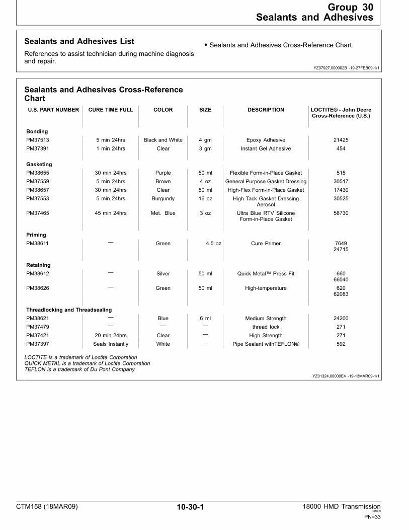
Sealants and Adhesives ListReferences to assist technician during machine diagnosisand repair.
• Sealants and Adhesives CrossReference Chart
Sealants and Adhesives CrossReferenceChartU.S. PART NUMBER CURE TIME FULL COLOR SIZE DESCRIPTION LOCTITE® John Deere
CrossReference (U.S.)
BondingPM37513 5 min 24hrs Black and White 4 gm Epoxy Adhesive 21425PM37391 1 min 24hrs Clear 3 gm Instant Gel Adhesive 454
GasketingPM38655 30 min 24hrs Purple 50 ml Flexible ForminPlace Gasket 515PM37559 5 min 24hrs Brown 4 oz General Purpose Gasket Dressing 30517PM38657 30 min 24hrs Clear 50 ml HighFlex ForminPlace Gasket 17430PM37553 5 min 24hrs Burgundy 16 oz High Tack Gasket Dressing
Aerosol30525
PM37465 45 min 24hrs Met. Blue 3 oz Ultra Blue RTV SiliconeForminPlace Gasket
58730
PrimingPM38611 — Green 4.5 oz Cure Primer 7649
24715
RetainingPM38612 — Silver 50 ml Quick Metal™ Press Fit 660
66040PM38626 — Green 50 ml Hightemperature 620
62083
Threadlocking and ThreadsealingPM38621 — Blue 6 ml Medium Strength 24200PM37479 — — — thread lock 271PM37421 20 min 24hrs Clear — High Strength 271PM37397 Seals Instantly White — Pipe Sealant withTEFLON® 592
LOCTITE is a trademark of Loctite CorporationQUICK METAL is a trademark of Loctite CorporationTEFLON is a trademark of Du Pont Company
CTM158 (18MAR09) 10301 18000 HMD Transmission031809
PN=33
Sealants and Adhesives
CTM158 (18MAR09) 10302 18000 HMD Transmission031809
PN=34

Group 35Restoration and Preservation
YZ07927,000002C 1927FEB091/1
DPSG,YZ01324,192 1911APR001/1
DPSG,YZ01324,191 1913MAR091/1
Restoration and Preservation ListReferences to assist technician during machine diagnosisand repair.
• Restoring Transmission From Storage• Preserving Transmission For Storage
Restoring Transmission From Storage1. Wash off all external grease with a safety solvent.
2. Remove covers or tape from all openings.
3. Drain transmission completely,
4. Fill transmission using procedure entitled “Fill TheTransmission With Oil” in the Lubricants andCoolants Section of this manual.
Preserving Transmission For StorageThis procedure applies to transmissions and componentsthat have been tested according to manufacturer testspecifications. The oil is drained before shipment.
The following procedure protects the unit and componentitems from rust and corrosion damage for approximatelyone year. Store the transmission in a dry area.
Internal Preservation
1. Seal all openings with moisture proof covers or tape.
2. Dispense 113 g (4 oz.) of NOXRUST®1 VCI 1052, oran equivalency, oil into drain hole.
External Preservation
Dip, spray, or brush all exposed unpainted surfaces withNOXRUST® X1103 or an equivalency.
1NOXRUST® is a product of Daubert Chemical Company.2NOXRUST® VCI 105 is a corrosioninhibitive lubricating oil usedto preserve ferrous metal parts in enclosed systems.3NOXRUST® X110 is a wax based, solvent type, cold applied,corrosion preventative used on ferrous and nonferrous metalsexposed to indoor or outdoor storage conditions.
CTM158 (18MAR09) 10351 18000 HMD Transmission031809
PN=35

Restoration and Preservation
CTM158 (18MAR09) 10352 18000 HMD Transmission031809
PN=36

Group 40Gasket/Anaerobic Sealant Application
YZ07927,000002D 1913MAR091/1
DPSG,YZ01324,574 1913MAR091/1
DPSG,YZ01324,575 1904FEB091/1
Gasket and Anaerobic SealantApplication ListReferences to assist technician during machine diagnosisand repair.
• Clean Surfaces• Apply Gasket Sealant
Clean SurfacesClean both surfaces to be joined using 100% isopropylalcohol. Loctite® 7070 ODCFree can be used as asubstitute. Wipe excess off with a clean cloth.
Apply Gasket SealantDispense approximately 1 to 2 ounces of PM38655flexible forminplace gasket (Loctite® 518) on a plasticsheet or table top. Avoid using excessive amounts thatmay be exposed for long periods of time. This will helpprevent contamination from surrounding atmosphere suchas dust with metal content. Using an ink roller or similardevice, apply to one surface of the joint by loading theroller from a plastic sheet and transferring the materialin a thin film to the joint. The application should be the
thinnest film possible, but provide complete coverage.This can be judged by the appearance of the joint once itis put together. Excessive amounts will cause runoff of thematerial. A small bead or buildup at the joint is permissibleand indicates good dispersion through the joint. Excesscan be wiped from the joint. Joining should take placewithin 3 minutes after sealant application. Apply propercap screw torque and sequence as applicable. Allow aminimum of 1215 minutes before adding oil for test standusage.
CTM158 (18MAR09) 10401 18000 HMD Transmission031809
PN=37

Gasket/Anaerobic Sealant Application
CTM158 (18MAR09) 10402 18000 HMD Transmission031809
PN=38

Section 50HMD Transmission
Contents
Page
Group 05—Tools and Other MaterialsTools and Other Materials List ..................... 5005 1Service Equipment and Tools ...................... 5005 1Other Material.............................................. 5005 1
Group 10—Repair SpecificationsRepair Specifications List ............................ 5010 1Specifications .............................................. 5010 2
Group 11—K Series TransmissionK Series Transmission List .......................... 5011 1K Series 18000 TransmissionIdentification ............................................ 5011 2
K Series Front Cover Group........................ 5011 6K Series Rear Cover Group......................... 5011 8K Series Seal Retainer Group ..................... 501110K Series Gear Ratio Group.......................... 501112K Series Lube Pump Group......................... 501114K Series Yoke Group ................................... 501116K Series Hydraulic Shifter Group................. 501118
Group 15—Repair and AdjustmentsRepair and Adjustments List........................ 5015 1Remove Lube Pump Group......................... 5015 1Remove Brake Caliper Assembly................ 5015 4Remove Disc Brake With Yoke AndCompanion Flange Group ....................... 5015 5
Remove Hydraulic Shift Group.................... 5015 6Remove Yoke Group ................................... 501510Remove Seal Retainer Group ..................... 501511Remove Hydraulic Motor AdapterGroup....................................................... 501512
Remove Bearing Retainer Group ................ 501513Remove Input Housing Group..................... 501514Remove Shaft Assembly Groups ................ 501517Disassemble And Assemble OutputHousing Group ........................................ 501518
Disassemble And Assemble FirstStage Shaft Assembly ............................. 501519
Disassemble And AssembleSecond Stage Shaft Assembly ................ 501521
Disassemble And Assemble ThirdStage Shaft Assembly ............................. 501522
Disassemble Third Stage ShaftAssembly ................................................. 501524
Assemble Third Stage ShaftAssembly ................................................. 501528
Install Shaft Assembly Groups .................... 501533Assemble Input Housing.............................. 501535Oil Seal ........................................................ 501538Second Stage (Intermediate) ShaftBearing Adjustment ................................. 501539
Install Bearing Retainer Group .................... 501540Input Shaft Bearing Adjustment................... 501541
Page
Install Hydraulic Motor AdapterGroup....................................................... 501542
Output Shaft Bearing Adjustment ................ 501543Install Seal Retainer Group ......................... 501544Install Yoke Group ....................................... 501545Install Hydraulic Shift Group........................ 501546Install Yoke Flange Group ........................... 501552Install Brake Disc And CompanionFlange Group........................................... 501553
Remove and Replace CaliperBrake Lining Assembly ............................ 501555
Assemble and Install Lube PumpGroup....................................................... 501558
Group 20—Transmission OperationTransmission Operation List ........................ 5020 1General Information..................................... 5020 1Internal Lubrication...................................... 5020 2Lube Pump Operation ................................. 5020 3Gear Ratio Activation................................... 5020 4
Group 25—Brake OperationBrake Operation List.................................... 5025 1Brake Operation .......................................... 5025 1
Group 30—Hydraulic Shifter OperationHydraulic Shifter Operation List................... 5030 1Hydraulic Shifter Operation ......................... 5030 1
Group 35—TroubleshootingTroubleshooting List .................................... 5035 1Transmission ............................................... 5035 1Hydraulic Shifter .......................................... 5035 1
CTM158 (18MAR09) 501 18000 HMD Transmission031809
PN=1

Contents
CTM158 (18MAR09) 502 18000 HMD Transmission031809
PN=2

Group 05Tools and Other Materials
YZ07927,000002E 1927FEB091/1
YZ01324,000002B 1917MAR091/1
YZ01324,000003F 1904FEB091/1
Tools and Other Materials ListReferences to assist technician during machine diagnosisand repair.
• Service Equipment and Tools• Other Material
Service Equipment and ToolsNOTE: Order tools according to information given in
the U.S. SERVICEGARD™ Catalog or from the
European Microfiche Tool Catalog (MTC). Sometools available from a local supplier.
SERVICEGARD is a trademark of Deere & Company
Other MaterialNumber Name Use
PM37421 (U.S.)Loctite® 2621 (U.S.)
High Strength Threadlocker To seal cap screws.
Loctite® 7070 (U.S.) ODCFree Cleaner To clean all threaded fasteners andsurfaces that will be joined.
PM38657 (U.S.)Loctite® 518 or 510 (U.S.)
Gasket Eliminator® Flange Sealant2 To seal joined surfaces.
PM37509 (U.S.)Loctite® 76493 (U.S.)
Primer N To ensure proper cure of cap screwsand reduce curing time.
PM38613 (U.S.) Pipe Sealer with Teflon®4 To seal all pipe thread fittings.
1Loctite is a registered trademark of Loctite Corporation2Eliminator is a registered trademark of Loctite Corporation3Equivalent primers may be used but must meet environmentaland safety standards of manufacturer.4Teflon is a registered trademark of E.I. DuPont de Nemours Co., Inc.
CTM158 (18MAR09) 50051 18000 HMD Transmission031809
PN=41

Tools and Other Materials
CTM158 (18MAR09) 50052 18000 HMD Transmission031809
PN=42

Group 10Repair Specifications
YZ07927,000002F 1927FEB091/1
Repair Specifications ListReferences to assist technician during machine diagnosisand repair.
• Specifications
CTM158 (18MAR09) 50101 18000 HMD Transmission031809
PN=43
Repair Specifications
Continued on next page DPSG,YZ01324,82 1917MAR091/2
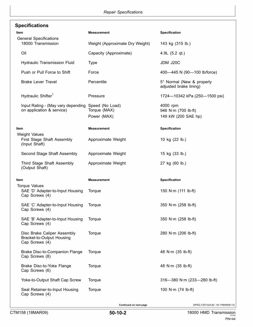
SpecificationsItem Measurement Specification
General Specifications18000 Transmission Weight (Approximate Dry Weight) 143 kg (315 lb.)
Oil Capacity (Approximate) 4.9L (5.2 qt.)
Hydraulic Transmission Fluid Type JDM J20C
Push or Pull Force to Shift Force 400—445 N (90—100 lb/force)
Brake Lever Travel Percentile 5° Normal (New & properlyadjusted brake lining)
Hydraulic Shifter1 Pressure 1724—10342 kPa (250—1500 psi)
Input Rating (May vary dependingon application & service)
Speed (No Load)Torque (MAX)
4000 rpm946 N∙m (700 lbft)
Power (MAX) 149 kW (200 SAE hp)
Item Measurement Specification
Weight ValuesFirst Stage Shaft Assembly(Input Shaft)
Approximate Weight 10 kg (22 lb.)
Second Stage Shaft Assembly Approximate Weight 15 kg (33 lb.)
Third Stage Shaft Assembly(Output Shaft)
Approximate Weight 27 kg (60 lb.)
Item Measurement Specification
Torque ValuesSAE ’D’ AdaptertoInput HousingCap Screws (4)
Torque 150 N∙m (111 lbft)
SAE ’C’ AdaptertoInput HousingCap Screws (4)
Torque 350 N∙m (258 lbft)
SAE ’B’ AdaptertoInput HousingCap Screws (4)
Torque 350 N∙m (258 lbft)
Disc Brake Caliper AssemblyBrackettoOutput HousingCap Screws (4)
Torque 280 N∙m (206 lbft)
Brake DisctoCompanion FlangeCap Screws (8)
Torque 48 N∙m (35 lbft)
Brake DisctoYoke FlangeCap Screws (6)
Torque 48 N∙m (35 lbft)
YoketoOutput Shaft Cap Screw Torque 316—380 N∙m (233—280 lbft)
Seal RetainertoInput HousingCap Screws (4)
Torque 100 N∙m (74 lbft)
CTM158 (18MAR09) 50102 18000 HMD Transmission031809
PN=44

Repair Specifications
DPSG,YZ01324,82 1917MAR092/2
Item Measurement Specification
Torque ValuesBearing RetainertoInput HousingCap Screws (4)
Torque 100 N∙m (74 lbft)
Magnet Drain PlugtoInputHousing
Torque 60 N∙m (44 lbft)
Pipe PlugtoOutput Housing (1/8”) Torque 20 N∙m (15 lbft)
Pipe PlugtoOutput Housing (3/8”) Torque 35 N∙m (25 lbft)
Pipe PlugtoInput Housing (3/8”) Torque 35 N∙m (25 lbft)
Pipe PlugtoLube PumpGroup (3/8”)
Torque 35 N∙m (25 lbft)
Pipe PlugtoLube PumpGroup (1/4")
Torque 25 N∙m (20 lbft)
Input HousingtoOutput HousingCap Screws (14)
Torque 100 N∙m (74 lbft)
Lube PumptoOutput HousingCap Screws (6)
Torque 11 N∙m (97 lbft)
Hydraulic ShiftertoInput HousingCap Screws (2)
Torque 100 N∙m (74 lbft)
Hydraulic Cylinder CaptoShifterCap
Torque 68 N∙m (50 lbft)
Shim Pack RangeShim Pack Range For Input &Intermediate Shafts
Range .14—1.44 mm (.005—.056 in)
Shim Pack Range For Output Shaft Range .07—2.41 mm (.003—.094 in)
Shim Pack For BearingRetainerShim A Thickness .051 mm (.002 in)
Shim B Thickness .076 mm (.003 in)
Shim C Thickness .127 mm (.005 in)
Shim D Thickness .254 mm (.010 in)
Shim E Thickness .508 mm (.020 in)
All Shafts End Play .05—.13 mm (.002—.005 in)
1Not applicable in all components.
CTM158 (18MAR09) 50103 18000 HMD Transmission031809
PN=45

Repair Specifications
CTM158 (18MAR09) 50104 18000 HMD Transmission031809
PN=46

Group 11K Series Transmission
YZ07927,0000034 1927FEB091/1
K Series Transmission List
YZ9206—UN—23FE
B09
References to assist technician during machine diagnosisand repair.• K Series 18000 Transmission Identification• K Series Front Cover Group• K Series Rear Cover Group
• K Series Seal Retainer Group• K Series Gear Ratio Group• K Series Lube Pump Group• K Series Yoke Group• K Series Hydraulic Shifter Group
CTM158 (18MAR09) 50111 18000 HMD Transmission031809
PN=47
K Series Transmission
Continued on next page YZ07927,000003B 1913MAR091/2
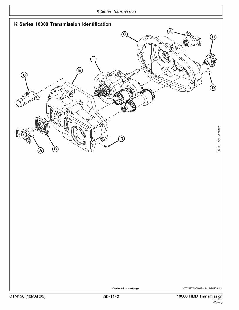
K Series 18000 Transmission Identification
G
F
E
D
BA
C
A
H
D
YZ9191—UN—06FE
B09
CTM158 (18MAR09) 50112 18000 HMD Transmission031809
PN=48

K Series Transmission
YZ07927,000003B 1913MAR092/2
A
C
D
F
H
B
E
GA
YZ9192—UN—06FE
B09
A—K Series Yoke GroupB—K Series Seal Retainer Group
C—K Series Hydraulic ShifterGroup
D—Breather Group
E—K Series Front Cover GroupF—K Series Gear Ratio Group
G—K Series Rear Cover GroupH—K Series Lube Pump Group
Other Related Information: • For Breather (D) related information refer to StandardModel Section 10, Group 10 and Install Hydraulic MotorAdapter Group Section 50, Group 15.
Item Measurement Specification
Pipe PlugtoRear Housing Torque 45—60 N∙m33—44 (lbft)
Item Measurement Specification
BreathertoHydraulic Motor Adapter Torque 20—25 N∙m14—18 (lbft)
Number Name Use
PM38613 (U.S.) Pipe Sealant with TEFLON Install Pipe PlugtoRear Housing
Number Name Use
PM38613 (U.S.) Pipe Sealant with TEFLON Install BreathertoHydraulicMotor Adapter
CTM158 (18MAR09) 50113 18000 HMD Transmission031809
PN=49

K Series Transmission
YZ07927,000003B 1913MAR093/2
Number Name Use
J13F (U.S.) Petroleum Jelly Apply to seal lip before assembly
Item Measurement Specification
Adjust all shafts End Play 0.05—0.13 mm.001—.005 (in)
Item Measurement Specification
Shim Pack Range for Input andIntermediate Shaft
End Play 0.14—1.44 mm.005—.056 (in)
Shim Pack Range for Output Shaft End Play 0.07—2.41 mm.002—.094 (in)
Number Name Use
PM38657 (U.S.) High Flex FormIn PlaceGasket Maker
Apply to Housing Flange beforeassembly
CTM158 (18MAR09) 50114 18000 HMD Transmission031809
PN=50

K Series Transmission
CTM158 (18MAR09) 50115 18000 HMD Transmission031809
PN=51

K Series Transmission
Continued on next page YZ07927,0000035 1918FEB091/2
K Series Front Cover Group
AB
C
D
E
F
GH
I
J
KL
M
N
O
H
GF
YZ9193—UN—06FE
B09
F
EH
J I G HK
D
C
B
A
G
N
O
M
YZ9194—UN—09FE
B09
A—Input HousingB—Cap Screw (13 Used)C—Magnetic Pipe PlugD—Identification Plate
E—Rivet (2 Used)F—Tapered Roller Bearing Cup
(3 Used)G—OringH—Shim Pack (2 Used)
I— Bearing RetainerJ—Cap Screw (4 Used)K—Pipe PlugL—Hex Socket Head Screw (4
Used)
M—OringN—Mounting AdapterO—Hex Head Cap Screw (2 Used)
Other Related Information:• Remove Input Housing Group Section 50, Group 15.
• Assemble Input Housing Section 50, Group 15.
CTM158 (18MAR09) 50116 18000 HMD Transmission031809
PN=52

K Series Transmission
YZ07927,0000035 1918FEB092/2
Number Name Use
PM37421 (U.S.) Thread Lock (highstrength) Apply to all threads
Number Name Use
PM38613 (U.S.) Pipe Sealant with Teflon Apply to Pipe Plug
Item Measurement Specification
Magnetic Pipe PlugtoFrontHousing Cover
Torque 6075 N∙m44—55 (lbft)
Item Measurement Specification
Front Housing CapscrewtoRearHousing
Torque 80—119 N∙m59—87 (lbft)
Item Measurement Specification
Bearing Retainer CapscrewtoFrontHousing
Torque 80—119 N∙m59—87 (lbft)
CTM158 (18MAR09) 50117 18000 HMD Transmission031809
PN=53

K Series Transmission
Continued on next page YZ07927,0000036 1918MAR091/2
K Series Rear Cover Group
C
B
K
A
BE
J
I
H
G
F
D
YZ9195—UN—12FE
B09
A
B B
ID
H GC Y
Z9196—UN—09FE
B09
A—Output HousingB—Dowel Pin (2 Used)C—Oil Deflector
D—Tapered Roller Bearing Cup(3 Used)
E—Pipe PlugF—Expansion Plug
G—Dipstick TubeH—Dipstick AssemblyI— Oil Seal
J— Internal Oil SealK—Pipe Plug
Other Related Information: • Disassemble And Assemble Output HousingGroup Section 50, Group 15.
CTM158 (18MAR09) 50118 18000 HMD Transmission031809
PN=54

K Series Transmission
YZ07927,0000036 1918MAR092/2
Number Name Use
PM38613 (U.S.) Pipe Sealant with Teflon Apply to Pipe Plug
Item Measurement Specification
Pipe PlugtoRear Housing Torque 20—25 N∙m14—18 (lbft)
Item Measurement Specification
Pipe PlugtoRear Housing Torque 35—45 N∙m25—33 (lbft)
• Install seals and expansion plug flush to below flush. • Install (H) with vent holes oriented as shown.
CTM158 (18MAR09) 50119 18000 HMD Transmission031809
PN=55

K Series Transmission
YZ07927,000003E 1925FEB091/1
K Series Seal Retainer Group
D
D
C
B
B
A
AC
E
E
YZ9200—UN—10FE
B09
A—OringB—Shim Pack
C—RetainerD—Capscrew (4 Used)
E—Oil Seal
Other Related Information:• Remove Seal Retainer Group Section 50, Group 15.
• Install Seal Retainer Group Section 50, Group 15.• Output Shaft Bearing Adjustment Section 50, Group 15.
Item Measurement Specification
Shim Pack Range for Output Shaft End Play 0.07—2.41 mm.002—.094 (in)
CTM158 (18MAR09) 501110 18000 HMD Transmission031809
PN=56

K Series Transmission
CTM158 (18MAR09) 501111 18000 HMD Transmission031809
PN=57

K Series Transmission
Continued on next page YZ07927,0000037 1918FEB091/2
K Series Gear Ratio Group
A
G
N
N
O
M
Q
Q
Q
B
Q
S
R
H
I
B
C
D
J
K
E
A
C
F
L
P
YZ9197—UN—10FE
B09
CTM158 (18MAR09) 501112 18000 HMD Transmission031809
PN=58

K Series Transmission
YZ07927,0000037 1918FEB092/2
A
L
S
G
B
C N
D
EO
P
B
A
F
J
QQR
M
YZ9198—UN—10FE
B09
A—Bearing Cone (2 Used)B—Thrust Bearing Race (2 Used)C—Single Row Ball Bearing (2
Used)D—Internal Snap RingE—Bearing Spacer
F—3rd Stage 71T GearG—Shift CollarH—Spring PinI— Shifter ForkJ—Shifter Shaft
K—Dowel PinL—Output ShaftM—3rd Stage 50T GearN—Ball BearingO—Internal Snap Ring
P—Bearing SpacerQ—Bearing Cone (2 Used)R—Shaft and Gear Assembly 26T
and 47TS—Input Shaft 21T
Other Related Information:• Gear Ratio Activation Section 50, Group 20.
• Gear Ratio Chart Section 10, Group 10.
CTM158 (18MAR09) 501113 18000 HMD Transmission031809
PN=59

K Series Transmission
YZ07927,0000038 1924FEB091/1
K Series Lube Pump Group
A
B
D
C
E
F
G
H
YZ9199—UN—10FE
B09
A—Cap Screw (6 Used)B—Pump Cover
C—1/4 Inch Pipe PlugD—3/8 Inch Pipe Plug
E—GasketF—Pump Assembly
G—Pump PlungerH—Pump Spring
Other Related Information:• Remove Lube Pump Group Section 50, Group 15.• Assemble and Install lube Pump Group Section 50,Group 15.
• Lube Pump Operation Section 50, Group 20.
Number Name Use
PM38613 (U.S.) Pipe Sealant with Teflon Apply to Pipe Plug
Number Name Use
PM38621 (U.S.) Thread Lock and Sealer(mediumstrength)
Apply to Lube Pump Cap Screw
Item Measurement Specification
Lube Pump Cap ScrewtoRearHousing
Torque 8.2 N∙m6 (lbft)
CTM158 (18MAR09) 501114 18000 HMD Transmission031809
PN=60

K Series Transmission
CTM158 (18MAR09) 501115 18000 HMD Transmission031809
PN=61

K Series Transmission
YZ07927,0000039 1925FEB091/1
K Series Yoke GroupA
C
A
B
C
DD
B
YZ9201—UN—10FE
B09
A—6C Yoke B—Oring C—Washer D—Hex Head Screw
IMPORTANT: All thread lock adhesive systemsrequire clean dry parts at assembly. CapScrew and the mating threaded hole mustbe free of oil and grease.
Other Related Information:• Remove Yoke Group Section 50, Group 15.• Install Yoke Group Section 50, Group 15.
Number Name Use
PM37421 (U.S.) High Strength Apply to Universal Joint YokeCap Screw
Item Measurement Specification
Yoke Cap ScrewtoOutput Shaft Torque 316—380 N∙m233—280 (lbft)
CTM158 (18MAR09) 501116 18000 HMD Transmission031809
PN=62

K Series Transmission
CTM158 (18MAR09) 501117 18000 HMD Transmission031809
PN=63

K Series Transmission
Continued on next page YZ07927,000003A 1925FEB091/2
K Series Hydraulic Shifter Group
A
B
B
M
L
C
D
E
E
E
F
E
F
K
L
JF
GH
I
YZ9202—UN—10FE
B09
CTM158 (18MAR09) 501118 18000 HMD Transmission031809
PN=64

K Series Transmission
YZ07927,000003A 1925FEB092/2
A
B
H
I
J
K
B
MC
D
L
EE G
F
YZ9203—UN—11FE
B09
A—Spacer CapB—OringC—OringD—Shifter Cap Sleeve
E—Backup RingF—Oring PackingG—Backup RingH—Clevis Pin
I— Cotter PinJ—Shifter Cap PistonK—Shifter CapL—Cap Screw (2 Used)
M—Hydraulic Cylinder Cap
Other Related Information:• Refer to “Hydraulic Shifter Operation” Section 50,Group 30.• Refer to “Remove Hydraulic Shift Group” Section 50,Group 15.
• Refer to “Install Hydraulic Shift Group” Section 50,Group 15.
Item Measurement Specification
Hydraulic ShiftertoInput HousingCap Screw
Torque 100 N∙m74 (lbft)
Hydraulic Cylinder CaptoShifter Cap Torque 68 N∙m50 (lbft)
CTM158 (18MAR09) 501119 18000 HMD Transmission031809
PN=65

K Series Transmission
CTM158 (18MAR09) 501120 18000 HMD Transmission031809
PN=66
Group 15Repair and Adjustments
YZ07927,0000030 1916MAR091/1
Continued on next page DPSG,YZ01324,57 1913MAR091/4
Repair and Adjustments ListReferences to assist technician during machine diagnosisand repair.
• Remove Lube Pump Group• Remove Brake Caliper Assembly• Remove Disc Brake With Yoke And Companion FlangeGroup• Remove Hydraulic Shift Group• Remove Yoke Group• Remove Seal Retainer Group• Remove Hydraulic Motor Adapter Group• Remove Bearing Retainer Group• Remove Input Housing Group• Remove Shaft Assembly Groups• Disassemble And Assemble Output Housing Group• Disassemble And Assemble First Stage Shaft Assembly• Disassemble And Assemble Second Stage ShaftAssembly
• Disassemble And Assemble Third Stage ShaftAssembly• Disassemble Third Stage Shaft Assembly• Assemble Third Stage Shaft Assembly• Install Shaft Assembly Groups• Assemble Input Housing• Oil Seal• Second Stage (Intermediate) Shaft Bearing Adjustment• Install Bearing Retainer Group• Input Shaft Bearing Adjustment• Install Hydraulic Motor Adapter Group• Output Shaft Bearing Adjustment• Install Seal Retainer Group• Install Yoke Group• Install Hydraulic Shift Group• Install Yoke Flange Group• Install Brake Disc And Companion Flange Group• Remove and Replace Caliper Brake Lining Assembly• Assemble and Install Lube Pump Group
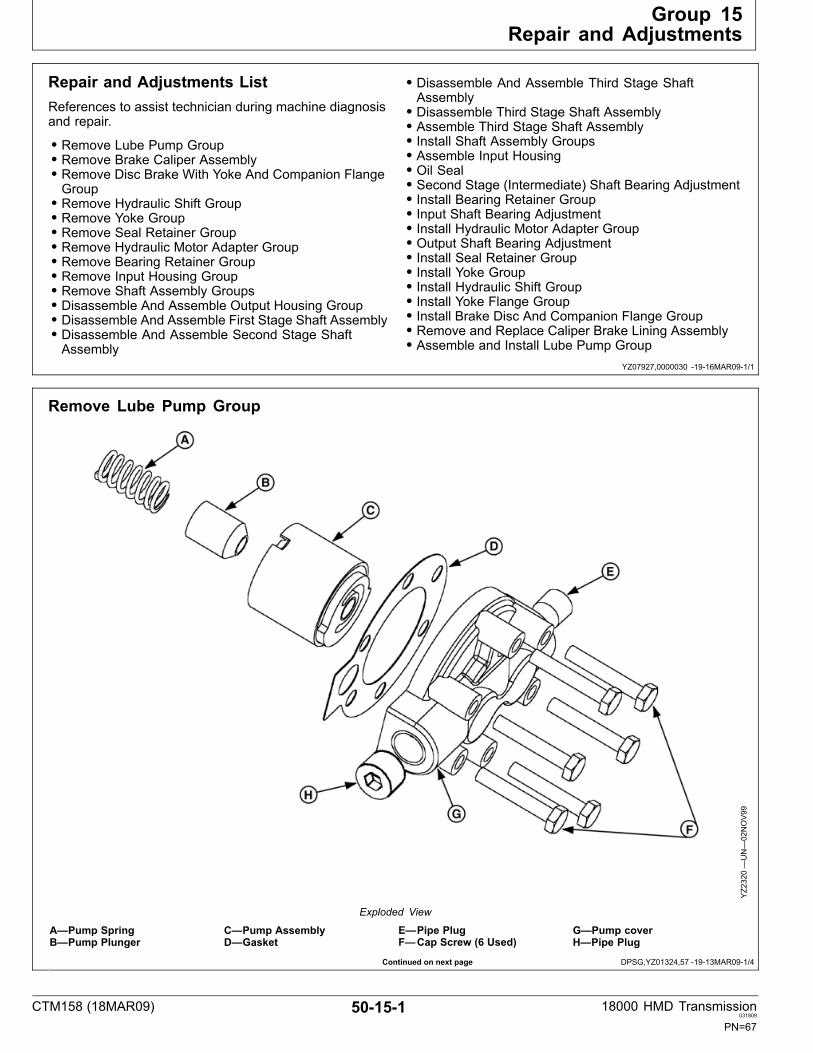
Remove Lube Pump Group
YZ2320—UN—02NOV99
Exploded View
A—Pump SpringB—Pump Plunger
C—Pump AssemblyD—Gasket
E—Pipe PlugF—Cap Screw (6 Used)
G—Pump coverH—Pipe Plug
CTM158 (18MAR09) 50151 18000 HMD Transmission031809
PN=67

Repair and Adjustments
DPSG,YZ01324,57 1913MAR092/4
Continued on next page DPSG,YZ01324,57 1913MAR093/4
1. Remove cap screws (A) from lube pump group.
2. Remove pump cover (B).
3. Check plugs (C and D) for wear and debris buildup.Clean out plug holes and replace plugs, if needed.
A—Cap Screws (6 Used)B—Pump Cover
C—PlugD—Plug
YZ2218—UN—09DEC99
4. Remove gasket (B) and pump assembly (A).
A—Pump Assembly B—Gasket
YZ2298—UN—09DEC99
CTM158 (18MAR09) 50152 18000 HMD Transmission031809
PN=68

Repair and Adjustments
DPSG,YZ01324,57 1913MAR094/4
5. Remove pump plunger (A).
6. Remove pump spring (B).
A—Pump Plunger B—Pump Spring
YZ2300—UN—09DEC99
CTM158 (18MAR09) 50153 18000 HMD Transmission031809
PN=69

Repair and Adjustments
DPSG,YZ01324,113 1913MAR091/1
Remove Brake Caliper Assembly1. Loosen two adjustment locking nuts (A) enough to
allow clearance between the caliper assembly (B) andthe disc brake (E).
2. Remove two nuts (C) securing caliper assembly tobracket (D).
3. Remove caliper assembly.
A—Lock Nuts (2)B—Caliper AssemblyC—Nuts (2)
D—BracketE—Disc Brake Y
Z2227—UN—04JAN00
CTM158 (18MAR09) 50154 18000 HMD Transmission031809
PN=70

Repair and Adjustments
DPSG,YZ01324,58 1916MAR091/1
Remove Disc Brake With Yoke AndCompanion Flange GroupNOTE: Not all 18000 models have disc brake options.
1. Remove cap screw (A).
2. Remove yoke washer (B).
3. Remove Oring (C).
4. Remove disc brake (G) and companion flangeassembly (F) together.1
NOTE: Proceed to next step if disassembly ofcompanion flange is necessary.
5. Remove hex nuts (D).
6. Remove lockwashers.
7. Remove clipped washers.
NOTE: Applies to companion flange only.
8. Remove cap screws (E).
9. Inspect brake bracket (H) for wear or damage.Remove and replace, if needed.
YZ2237—UN—12JU
N03
A—Cap ScrewB—Yoke WasherC—OringD—Hex Nuts (8)
E—Cap Screws (8)F—Companion FlangeG—Disc BrakeH—Brake Bracket
1Remove yoke on models without disc brake options.
CTM158 (18MAR09) 50155 18000 HMD Transmission031809
PN=71

Repair and Adjustments
DPSG,YZ01324,111 1916MAR091/12
Continued on next page DPSG,YZ01324,111 1916MAR092/12
Remove Hydraulic Shift GroupNOTE: The hydraulic shift group is optional and does
not apply to all 18000 transmissions.
1. Shift transmission to low range. Disconnect hydrauliclines.
2. Remove hydraulic cylinder cap (A).
A—Cylinder Cap
YZ2176—UN—26MAY
00
3. Remove two cap screws (A).
A—Cap Screws (2)
YZ2175—UN—26MAY
00
CTM158 (18MAR09) 50156 18000 HMD Transmission031809
PN=72

Repair and Adjustments
DPSG,YZ01324,111 1916MAR093/12
DPSG,YZ01324,111 1916MAR094/12
Continued on next page DPSG,YZ01324,111 1916MAR095/12
4. Remove shifter cap (A).
A—Shifter Cap
YZ2177—UN—26MAY
00
5. Remove and discard Oring (A) from outer rim ofshifter cap (B).
A—Oring B—Shifter Cap
YZ2166—UN—26MAY
00
6. Remove and discard Oring (A) and backup ring (B)from inside groove of shifter cap (C).
A—OringB—Backup Ring
C—Inner Groove of Shifter Cap
YZ2165—UN—30MAY
00
CTM158 (18MAR09) 50157 18000 HMD Transmission031809
PN=73

Repair and Adjustments
DPSG,YZ01324,111 1916MAR096/12
DPSG,YZ01324,111 1916MAR097/12
DPSG,YZ01324,111 1916MAR098/12
Continued on next page DPSG,YZ01324,111 1916MAR099/12
7. Remove cotter pin (B) and clevis pin (C) from shiftershaft (D) to disconnect shifter cap assembly (A).
A—Shifter Cap AssemblyB—Clevis Pin
C—Cotter PinD—Shifter Shaft
YZ2174—UN—26MAY
00
8. Pull shifter cap piston (A) and shifter cap sleeve (B)a part.
A—Shifter Cap Piston B—Shifter Cap Sleeve
YZ2168—UN—26MAY
00
9. Remove and discard Oring (A) from outer rim ofshifter cap sleeve (B).
A—Oring B—Shifter Cap Sleeve
YZ2167—UN—26MAY
00
10. Remove and discard backup ring (A) and Oring (B)from inner groove of shifter cap sleeve (C).
A—Backup RingB—Oring
C—Inner Groove of Shifter CapSleeve
YZ2163—UN—26MAY
00
CTM158 (18MAR09) 50158 18000 HMD Transmission031809
PN=74

Repair and Adjustments
DPSG,YZ01324,111 1916MAR0910/12
DPSG,YZ01324,111 1916MAR0911/12
DPSG,YZ01324,111 1916MAR0912/12
11. Remove and discard backup rings (A) and Oring (B)from shifter cap piston (C).
A—Backup Rings (2)B—Oring
C—Shifter Cap Piston
YZ2164—UN—26MAY
00
12. Remove spacer cap from input housing.
YZ2173—UN—26MAY
00
13. Remove and discard Orings (A & B).
Oring B—Oring
YZ2171—UN—26MAY
00
CTM158 (18MAR09) 50159 18000 HMD Transmission031809
PN=75
Repair and Adjustments
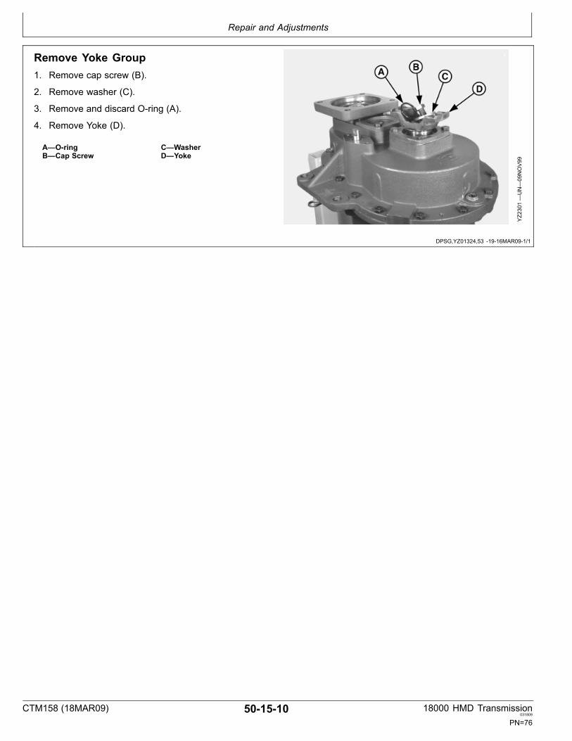
DPSG,YZ01324,53 1916MAR091/1
Remove Yoke Group1. Remove cap screw (B).
2. Remove washer (C).
3. Remove and discard Oring (A).
4. Remove Yoke (D).
A—OringB—Cap Screw
C—WasherD—Yoke
YZ2301—UN—09NOV99
CTM158 (18MAR09) 501510 18000 HMD Transmission031809
PN=76
Repair and Adjustments
DPSG,YZ01324,54 1916MAR091/1
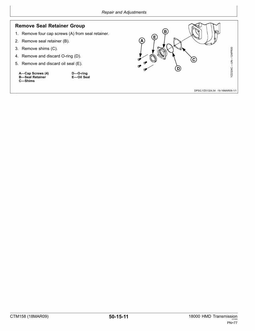
Remove Seal Retainer Group1. Remove four cap screws (A) from seal retainer.
2. Remove seal retainer (B).
3. Remove shims (C).
4. Remove and discard Oring (D).
5. Remove and discard oil seal (E).
A—Cap Screws (4)B—Seal RetainerC—Shims
D—OringE—Oil Seal Y
Z2324C
—UN—12APR00
CTM158 (18MAR09) 501511 18000 HMD Transmission031809
PN=77
Repair and Adjustments
DPSG,YZ01324,52 1916MAR091/2
DPSG,YZ01324,52 1916MAR092/2
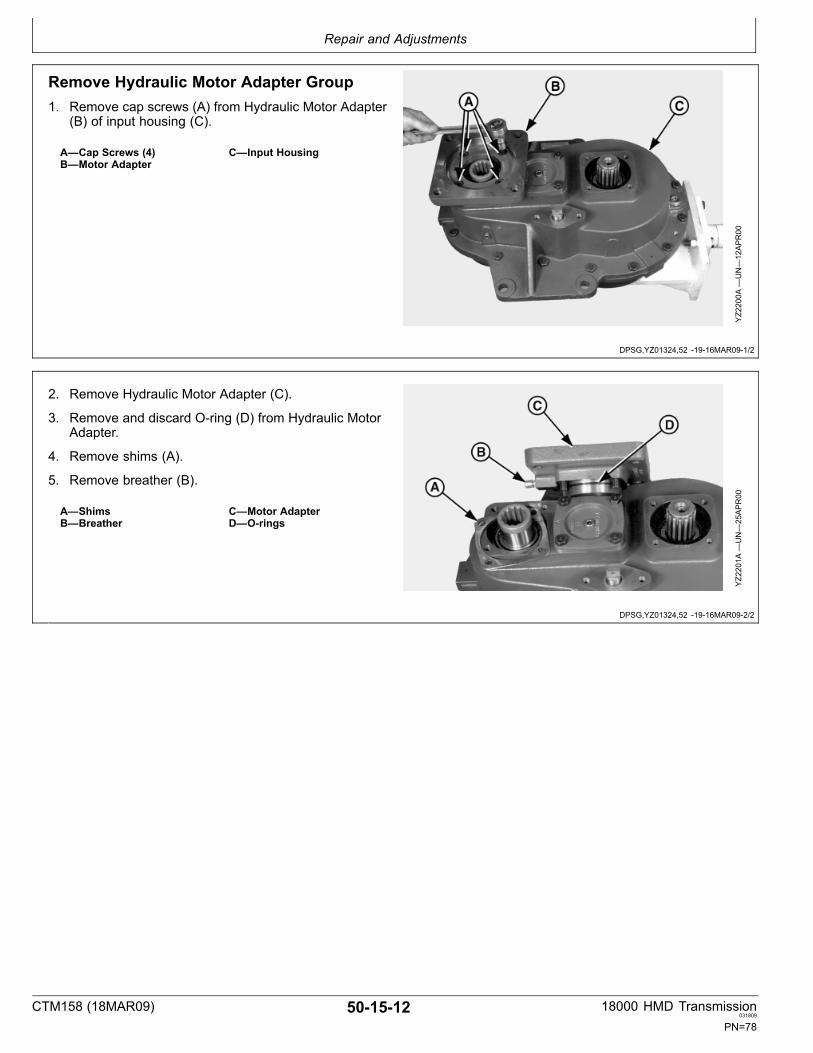
Remove Hydraulic Motor Adapter Group1. Remove cap screws (A) from Hydraulic Motor Adapter
(B) of input housing (C).
A—Cap Screws (4)B—Motor Adapter
C—Input Housing
YZ2200A
—UN—12APR00
2. Remove Hydraulic Motor Adapter (C).
3. Remove and discard Oring (D) from Hydraulic MotorAdapter.
4. Remove shims (A).
5. Remove breather (B).
A—ShimsB—Breather
C—Motor AdapterD—Orings
YZ2201A
—UN—25APR00
CTM158 (18MAR09) 501512 18000 HMD Transmission031809
PN=78

Repair and Adjustments
DPSG,YZ01324,105 1905FEB091/2
DPSG,YZ01324,105 1905FEB092/2
Remove Bearing Retainer Group1. Remove cap screws (A).
2. Remove bearing retainer (B).
A—Cap Screws (4) B—Bearing Retainer
YZ2204A
—UN—12APR00
3. Remove shims (B).
4. Remove and discard Oring (A).
A—Oring B—Shims
YZ2273—UN—10NOV99
CTM158 (18MAR09) 501513 18000 HMD Transmission031809
PN=79
Repair and Adjustments
Continued on next page DPSG,YZ01324,55 1916MAR091/5
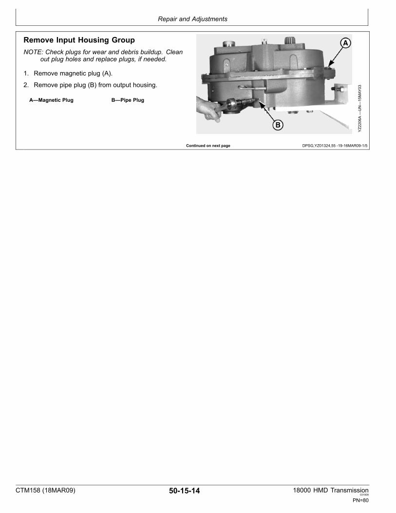
Remove Input Housing GroupNOTE: Check plugs for wear and debris buildup. Clean
out plug holes and replace plugs, if needed.
1. Remove magnetic plug (A).
2. Remove pipe plug (B) from output housing.
A—Magnetic Plug B—Pipe Plug
YZ2206A
—UN—15MAY
03
CTM158 (18MAR09) 501514 18000 HMD Transmission031809
PN=80

Repair and Adjustments
Continued on next page DPSG,YZ01324,55 1916MAR092/5
3. Use pencil magnet (C) to remove dowel pin.
NOTE: Pipe plug (B) is also displayed.
4. Remove dowel pin (D).
B—Pipe PlugC—Pencil Magnet
D—Dowel Pin
YZ2207A
—UN—12JU
N03
YZ2208B
—UN—12JU
N03
CTM158 (18MAR09) 501515 18000 HMD Transmission031809
PN=81
Repair and Adjustments
DPSG,YZ01324,55 1916MAR093/5
DPSG,YZ01324,55 1916MAR094/5
DPSG,YZ01324,55 1916MAR095/5
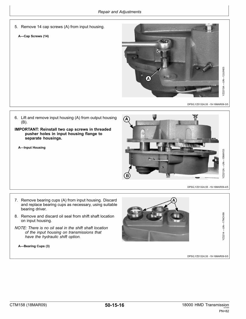
5. Remove 14 cap screws (A) from input housing.
A—Cap Screws (14)
YZ2210A
—UN—12JU
N03
6. Lift and remove input housing (A) from output housing(B).
IMPORTANT: Reinstall two cap screws in threadedpusher holes in input housing flange toseparate housings.
A—Input Housing
YZ2212A
—UN—15MAY
03
7. Remove bearing cups (A) from input housing. Discardand replace bearing cups as necessary, using suitablebearing driver.
8. Remove and discard oil seal from shift shaft locationon input housing.
NOTE: There is no oil seal in the shift shaft locationof the input housing on transmissions thathave the hydraulic shift option.
A—Bearing Cups (3)
YZ2214—UN—17NOV99
CTM158 (18MAR09) 501516 18000 HMD Transmission031809
PN=82

Repair and Adjustments
DPSG,YZ01324,56 1916MAR091/1
Remove Shaft Assembly Groups1. Remove oil deflector (A).
2. Install eye bolt to third stage gear assembly (B).
3. Lift and remove third stage (B) and shifter shaftassembly (C) from output housing.
NOTE: Tilt 1st and 2nd stage shaft assemblies toremove third stage and shifter shaft assemblyfrom output housing.
NOTE: The shifter shaft assembly consists of the shiftshaft, shift fork, and spirol pin.
4. Remove first (D) and second (E) stage shaftassemblies.
YZ2224A
—UN—15MAY
03
A—Oil DeflectorB—Third Stage Shaft AssemblyC—Shifter Shaft Assembly
D—First Stage Shaft AssemblyE—Second Stage Shaft
Assembly
CTM158 (18MAR09) 501517 18000 HMD Transmission031809
PN=83

Repair and Adjustments
DPSG,YZ01324,94 1916MAR091/2
DPSG,YZ01324,94 1916MAR092/2
Disassemble And Assemble Output Housing Group
YZ2325—UN—02NOV99
Exploded View
A—Pipe PlugB—Output HousingC—Dowel Pin (2)
D—Bearing Cup (3)E—Oil DeflectorF—Dipstick
G—Dipstick TubeH—Oil SealI— Oil Seal
J—Pipe Plug
1. Remove bearing cups (A). Discard and replace withnew bearing cups as necessary, using suitable bearingdriver.
2. Remove and discard oil seals. Replace with new oilseals, using suitable seal drivers.
3. Check pipe plugs for wear and debris buildup. Cleanout plug holes and replace plugs, if needed.
4. Remove and inspect dipstick tube. Clean and replace,if necessary.
5. Inspect dowel pins for damage. Replace, if necessary.
A—Bearing Cups (3)
YZ2242—UN—05JAN00
CTM158 (18MAR09) 501518 18000 HMD Transmission031809
PN=84

Repair and Adjustments
Continued on next page DPSG,YZ01324,77 1917MAR091/3
Disassemble And Assemble First Stage Shaft Assembly
YZ2309—UN—05JU
N00
Exploded View
A—First Stage Shaft Assembly B—Bearing Cone (2)
CTM158 (18MAR09) 501519 18000 HMD Transmission031809
PN=85

Repair and Adjustments
DPSG,YZ01324,77 1917MAR092/3
DPSG,YZ01324,77 1917MAR093/3
1. Remove bearing using suitable bearing puller.
2. Turn shaft over.
YZ2285—UN—05OCT99
3. Remove bearing using suitable bearing puller.
Assembly is reverse of disassembly.
NOTE: Lube bearings before installation.
When installing bearing cones, use suitablebearing driver.
YZ2286—UN—05OCT99
CTM158 (18MAR09) 501520 18000 HMD Transmission031809
PN=86

Repair and Adjustments
DPSG,YZ01324,78 1917MAR091/2
DPSG,YZ01324,78 1917MAR092/2
Disassemble And Assemble Second Stage Shaft Assembly
YZ2310A
—UN—29OCT99
Exploded View
A—Bearing Cone (2) B—Second Stage ShaftAssembly1
1The large gear is a shrunk fit to shaft splined shaft. Itis not a serviceable item.
Remove bearings (A) using suitable bearing puller.
Assembly is reverse of disassembly.
NOTE: Lube bearings before installation.
When installing bearing cones, use suitablebearing driver.
A—Bearings (2)
YZ2240—UN—02NOV99
CTM158 (18MAR09) 501521 18000 HMD Transmission031809
PN=87

Repair and Adjustments
Continued on next page DPSG,YZ01324,79 1917MAR091/2
Disassemble And Assemble Third Stage Shaft Assembly
NOTE: Ball (L) and detent spring (M) not usedwith hydraulic shifter option.
YZ2311A
—UN—01JU
N00
Exploded View
A—Cap ScrewB—WasherC—OringD—YokeE—Bearing Cone (2)
F—Thrust Race (2)G—Bearing (2)H—Snap RingI— SpacerJ—Third Stage Gear
K—Output ShaftL—Ball (2)M—Detent SpringN—Shift CollarO—Third Stage Gear
P—Bearing (2)Q—SpacerR—Snap Ring
CTM158 (18MAR09) 501522 18000 HMD Transmission031809
PN=88
Repair and Adjustments
DPSG,YZ01324,79 1917MAR092/2
YZ2312—UN—01JU
N00
CrossSectional View
A—Cap ScrewB—WasherC—OringD—YokeE—Bearing Cone (2)
F—Thrust Race (2)G—Bearing (2)H—Snap RingI— SpacerJ—Third Stage Gear
K—Output ShaftL—Ball (2)M—Detent SpringN—Shift CollarO—Third Stage Gear
P—Bearing (2)Q—SpacerR—Snap Ring
CTM158 (18MAR09) 501523 18000 HMD Transmission031809
PN=89
Repair and Adjustments
DPSG,YZ01324,193 1916MAR091/8
Continued on next page DPSG,YZ01324,193 1916MAR092/8
Disassemble Third Stage Shaft Assembly1. Remove gear and bearing cone using suitable gear
puller.
2. Remove thrust race.
YZ2296—UN—05OCT99
3. Remove bearing (A).
4. Remove spacer (B).
A—Bearing B—Spacer
YZ2247—UN—02NOV99
CTM158 (18MAR09) 501524 18000 HMD Transmission031809
PN=90

Repair and Adjustments
DPSG,YZ01324,193 1916MAR093/8
Continued on next page DPSG,YZ01324,193 1916MAR094/8
5. Remove snap ring (A).
CAUTION: Snap ring under a lot of pressure.Use extreme care.
6. Remove bearing (B).
A—Snap Ring B—Bearing
YZ2248—UN—02NOV99
7. Lift shift collar (A) to expose detent spring and balls.
CAUTION: Detent spring and balls under pressure.Use extreme caution when removing shift collar.
NOTE: Detent spring and balls not used inhydraulic shifter option.
A—Shift Collar
YZ2294—UN—04JAN00
CTM158 (18MAR09) 501525 18000 HMD Transmission031809
PN=91

Repair and Adjustments
DPSG,YZ01324,193 1916MAR095/8
Continued on next page DPSG,YZ01324,193 1916MAR096/8
8. Remove shift collar (A), detent spring (B) and balls (C).
9. Turn shaft assembly over.
A—Shift CollarB—Detent Spring
C—Balls (2)
YZ2295—UN—04JAN00
10. Remove gear and bearing cone using suitable gearpuller.
11. Remove thrust race.
YZ2293—UN—05OCT99
CTM158 (18MAR09) 501526 18000 HMD Transmission031809
PN=92

Repair and Adjustments
DPSG,YZ01324,193 1916MAR097/8
DPSG,YZ01324,193 1916MAR098/8
12. Remove bearing (A).
13. Remove spacer (B).
A—Bearing B—Spacer
YZ2291—UN—04JAN00
14. Remove snap ring (B).
CAUTION: Snap ring under a lot of pressure.Use extreme care.
15. Remove bearing (A).
A—Bearing B—Snap Ring
YZ2250—UN—02NOV99
CTM158 (18MAR09) 501527 18000 HMD Transmission031809
PN=93

Repair and Adjustments
Continued on next page DPSG,YZ01324,92 1917MAR091/11
Assemble Third Stage Shaft Assembly1. Install ball, detent spring, and ball in output shaft using
suitable spring and ball loading sleeve (A).
2. Press shift collar (B) over ball and spring location ofoutput shaft using suitable driver (C). Remove springand ball loading sleeve.
NOTE: Detent spring and balls not used inhydraulic shifter option.
A—Spring and Ball LoadingSleeve
B—Shift Collar
C—Driver
YZ2243—UN—28JU
L03
YZ2255—UN—05OCT99
CTM158 (18MAR09) 501528 18000 HMD Transmission031809
PN=94
Repair and Adjustments
DPSG,YZ01324,92 1917MAR092/11
DPSG,YZ01324,92 1917MAR093/11
Continued on next page DPSG,YZ01324,92 1917MAR094/11
3. Install bearing (A), using suitable bearing driver.
NOTE: Lube bearings before installation.
Press outer race of bearing.
4. Install snap ring (B) to third stage gear.
CAUTION: Snap ring under a lot of pressure.Use extreme care.
A—Bearing B—Snap Ring
YZ2250X
—UN—25JU
N03
5. Press gear assembly onto output shaft using suitabledriver.
IMPORTANT: Make sure that gear is installed wheresplined side of gear faces towards the shift collar.
NOTE: Press inner race of bearing.
YZ2246X
—UN—25JU
N03
6. Install spacer (A).
7. Install bearing (B), using suitable bearing driver.
NOTE: Lube bearings before installation.
Press inner race of bearing.
A—Spacer B—Bearing
YZ2246Z
—UN—25JU
N03
CTM158 (18MAR09) 501529 18000 HMD Transmission031809
PN=95

Repair and Adjustments
DPSG,YZ01324,92 1917MAR095/11
Continued on next page DPSG,YZ01324,92 1917MAR096/11
8. Install thrust race (A).
A—Thrust Race
YZ2249—UN—05JAN00
9. Press bearing cone (A) onto output shaft until contactwith thrust race (B), using suitable bearing driver.
A—Bearing Cone B—Thrust Race
YZ2253—UN—19MAR03
CTM158 (18MAR09) 501530 18000 HMD Transmission031809
PN=96

Repair and Adjustments
DPSG,YZ01324,92 1917MAR097/11
DPSG,YZ01324,92 1917MAR098/11
Continued on next page DPSG,YZ01324,92 1917MAR099/11
10. Install bearing (B), using suitable bearing driver.
NOTE: Lube bearings before installation.
Press outer race of bearing.
CAUTION: Snap ring under a lot of pressure.Use extreme care.
11. Install snap ring (A) into third stage gear.
A—Snap Ring B—Bearing
YZ2248—UN—02NOV99
12. Press gear assembly onto output shaft using suitabledriver.
IMPORTANT: Make sure that gear is installed wheresplined side of gear faces towards the shift collar.
NOTE: Press inner race of bearing.
YZ2244—UN—05OCT99
13. Install spacer (A).
14. Install bearing (B), using suitable bearing driver.
NOTE: Lube bearings before installation.
Press inner race of bearing.
A—Spacer B—Bearing
YZ2247X
—UN—25JU
N03
CTM158 (18MAR09) 501531 18000 HMD Transmission031809
PN=97

Repair and Adjustments
DPSG,YZ01324,92 1917MAR0910/11
DPSG,YZ01324,92 1917MAR0911/11
15. Install thrust race (A).
16. Press bearing cone (B), using suitable bearing driver,onto output shaft until contact with thrust race (A).
A—Thrust Race B—Bearing Cone
YZ2245—UN—05JAN00
17. Engage shift collar to ensure that it works properly.
YZ2252—UN—05OCT99
CTM158 (18MAR09) 501532 18000 HMD Transmission031809
PN=98
Repair and Adjustments
DPSG,YZ01324,99 1917MAR091/4
Continued on next page DPSG,YZ01324,99 1917MAR092/4
Install Shaft Assembly Groups1. Install bearing cups (A) into output housing.
A—Bearing Cups (3)
YZ2242A
—UN—16MAY
03
2. Install 1st (A) and 2nd (B) stage shaft assemblies intooutput housing.
3. Install spirol pin to connect shift fork to shifter shaft.
NOTE: First and second stage assemblies may needto be rocked forward to install 3rd stage toavoid damage to bearing cage.
4. Install shifter shaft assembly (C) and 3rd stage shaftassembly (D) simultaneously into output housing.
IMPORTANT: Make sure shift fork sits in groove ofshift collar on 3rd stage shaft assemblyto work properly.
Make sure shifter sits in shift shaft locationof output housing.
NOTE: When installed, dowel pin rests in groove ofshift shaft to prevent overshifting.
Spin gear to make sure all gears spin freely.
YZ2271A
—UN—16MAY
03
A—First Stage Shaft AssemblyB—Second Stage Shaft
Assembly
C—Shifter Shaft AssemblyD—Third Stage Shaft Assembly
CTM158 (18MAR09) 501533 18000 HMD Transmission031809
PN=99

Repair and Adjustments
DPSG,YZ01324,99 1917MAR093/4
DPSG,YZ01324,99 1917MAR094/4
5. Install oil deflector (A).
A—Oil Deflector
YZ2304—UN—05JAN00
6. Place bearing cups (A) on 1st, 2nd and 3rd stage shaftassemblies.
A—Bearing Cups (3)
YZ2343—UN—12APR00
CTM158 (18MAR09) 501534 18000 HMD Transmission031809
PN=100

Repair and Adjustments
Continued on next page DPSG,YZ01324,100 1916MAR091/5
Assemble Input Housing
YZ2324—UN—03NOV99
Exploded View
A—Cap Screw (4)B—OringC—Hydraulic Motor AdapterD—Breather (7/16 psi)1E—OringF—Shim
G—Bearing Cup (3)H—Oil Seal2I— Input HousingJ— Identification PlateK—Magnetic PlugL—Drive Screw (2)
M—Cap Screw (14)N—ShimO—OringP—Seal RetainerQ—Oil SealR—Cap Screw (4)
S—Cap Screw (4)T—Pipe PlugU—Bearing RetainerV—OringW—Shim
1Standard Model has pipe plug in this location.2Oil Seal is not present in transmissions with hydraulic shift option.
CTM158 (18MAR09) 501535 18000 HMD Transmission031809
PN=101

Repair and Adjustments
DPSG,YZ01324,100 1916MAR092/5
DPSG,YZ01324,100 1916MAR093/5
Continued on next page DPSG,YZ01324,100 1916MAR094/5
1. Clean surfaces of input and output housings.
2. Apply flexible forminplace gasket to surface of outputhousing.
YZ2342—UN—12APR00
3. Insert dowel pins (A).
4. Install input housing to output housing.
A—Dowel Pins (2)
YZ2352—UN—12APR00
5. Clean and prime cap screws. Apply high strengththread lock to cap screws (14).
6. Install and tighten cap screws.Specification
Input HousingtoOutputHousing Cap Screws(14)—Torque................................................................ 100 N∙m (74 lbft)
YZ2265—UN—05OCT99
CTM158 (18MAR09) 501536 18000 HMD Transmission031809
PN=102

Repair and Adjustments
DPSG,YZ01324,100 1916MAR095/5
NOTE: Apply pipe sealer with teflon® to plugthreads before installing.
7. Install dowel pin (A) and pipe plug (B).
8. Install and tighten magnetic plug (C).Specification
Magnetic DrainPlugtoInputHousing—Torque............................................................ 60 N∙m (44 lbft)
A—Dowel PinB—Pipe Plug
C—Magnetic Plug
YZ2208C
—UN—16MAY
03
CTM158 (18MAR09) 501537 18000 HMD Transmission031809
PN=103

Repair and Adjustments
DPSG,YZ01324,194 1905FEB091/1
Oil SealIMPORTANT: There is no oil seal in the shift shaft
location of the input housing on transmissionsthat have the hydraulic shift option.
Install oil seal (A) to shift shaft location on input housing,using suitable seal driver.
A—Oil Seal
YZ2180—UN—01JU
N00
CTM158 (18MAR09) 501538 18000 HMD Transmission031809
PN=104

Repair and Adjustments
DPSG,YZ01324,195 1916MAR091/4
DPSG,YZ01324,195 1916MAR092/4
DPSG,YZ01324,195 1916MAR093/4
DPSG,YZ01324,195 1916MAR094/4
Second Stage (Intermediate) ShaftBearing Adjustment1. Install bearing retainer, without Oring.
YZ2355—UN—24APR00
2. Install and tighten two cap screws (A).Specification
Capscrews—Torque..................................................... 4.5 N∙m (40 lbin)
IMPORTANT: Make sure that 2 cap screwsare 180° apart.
3. Rotate or oscillate gear train to seat bearings.
A—Cap Screws (2)
YZ2356—UN—24APR00
4. Retorque cap screws again to make sure they aretorqued evenly at 4.5 N∙m (40 lbin).
5. Rotate or oscillate gear train again.
YZ2357—UN—24APR00
6. Using a feeler gage, measure the gap between thebearing retainer and the input housing at the two capscrews.
7. Calculate the average of the two readings and add.20 mm (.008 in) to determine shim pack thickness toobtain .05 .13 mm (.002 .005 in) end play.
8. Loosen cap screws and remove bearing retainer. YZ2358—UN—24APR00
CTM158 (18MAR09) 501539 18000 HMD Transmission031809
PN=105

Repair and Adjustments
YZ01324,0000047 1905FEB091/3
YZ01324,0000047 1905FEB092/3
YZ01324,0000047 1905FEB093/3
Install Bearing Retainer Group1. Install shims (A).
NOTE: Refer to Second Stage Bearing Adjustmentto determine shim pack thickness.
2. Install Oring (B) to bearing retainer.
3. Install bearing retainer (C) to input housing.
A—ShimsB—ORing
C—Bearing Retainer
YZ2150—UN—24APR00
4. Clean and prime cap screws. Apply high strengththreadlocker to cap screws (4).
5. Install and tighten cap screws.Specification
Bearing RetainertoInputHousing Cap Screws(4)—Torque.................................................................. 100 N∙m (74 lbft)
YZ2151—UN—24APR00
Verify End Play
End play can be verified after final assembly by removing3/8” pipe plug from center of bearing retainer and screwinga 3/8 16 cap screw into the center of the second stageshaft. Place a dial indicator on the input housing with theprobe zeroed in at the top of the hex head. Using prybars, exert a force under the head and read movement atindicator dial. Readjust shim pack thickness, if necessary,to obtain specified end play.
SpecificationSecond Stage BearingAdjustment—End Play..................................05 .13 mm (.002 .005 in)
Apply pipe sealer with Teflon® and reinstall 3/8” pipe plugto center of bearing retainer.
YZ2359—UN—24APR00
CTM158 (18MAR09) 501540 18000 HMD Transmission031809
PN=106

Repair and Adjustments
DPSG,YZ01324,196 1917MAR091/2
DPSG,YZ01324,196 1917MAR092/2
Input Shaft Bearing AdjustmentNOTE: Perform without pump installed due to
spring pressure.
1. Install hydraulic motor adapter (A), without Oring.
2. Install and tighten two cap screws (B).Specification
Cap screws—Torque.................................................... 4.5 N∙m (40 lbin)
IMPORTANT: Make sure that 2 cap screwsare 180° apart.
3. Rotate or oscillate gear train to seat bearings.
4. Retorque cap screws again to make sure they aretorqued evenly at 4.5 N∙m (40 lbin).
5. Rotate or isolate gear train again.
YZ2152—UN—25APR00
A—Motor Adapter B—Cap Screws (2)
6. Using a feeler gage, measure the gap between thebearing retainer and the input housing at the two capscrews.
7. Calculate the average of the two readings. Add .18mm (.007 in) to determine shim pack thickness toobtain .05 .13 mm (.002 .005 in) end play.
8. Loosen cap screws and remove hydraulic motoradapter.
YZ2153—UN—25APR00
CTM158 (18MAR09) 501541 18000 HMD Transmission031809
PN=107

Repair and Adjustments
DPSG,YZ01324,118 1916MAR091/2
DPSG,YZ01324,118 1916MAR092/2
Install Hydraulic Motor Adapter Group1. Install shims (A).
NOTE: Refer to Input Shaft Bearing Adjustment todetermine shim pack thickness.
2. Install Oring (D) to Hydraulic Motor Adapter.
3. Install breather (B) to Hydraulic Motor Adapter.Specification
BreathertoHydraulicMotor Adapter—Torque......................................................... 20—25 N∙m
14—18 (lbft)
4. Install Hydraulic Motor Adapter (C) to input housing.
YZ2201A
—UN—25APR00
A—ShimsB—Breather
C—Hydraulic Motor AdapterD—Oring
5. Clean and prime cap screws. Apply high strengththread lock to cap screws (4).
6. Install and tighten cap screws.Specification
Hydraulic MotorAdaptertoInputHousing Cap Screws(4)—Torque.................................................................150 N∙m (111 lbft)
7. Install Oring inside motor adapter.
Verify End Play
End play can be verified after final assembly by placingdial indicator probe at the end of the shaft and exertingforce from the opposite end of the shaft. Read movementat indicator dial and readjust shim pack thickness, ifnecessary, to obtain specified end play.
SpecificationInput Shaft BearingAdjustment—End Play..................................05 .13 mm (.002 .005 in)
YZ2272—UN—12APR00
CTM158 (18MAR09) 501542 18000 HMD Transmission031809
PN=108

Repair and Adjustments
DPSG,YZ01324,197 1916MAR091/3
DPSG,YZ01324,197 1916MAR092/3
DPSG,YZ01324,197 1916MAR093/3
Output Shaft Bearing Adjustment1. Install seal retainer, without Oring.
YZ2155—UN—25APR00
2. Install and tighten two cap screws.Specification
Cap screws—Torque.................................................... 4.5 N∙m (40 lbin)
IMPORTANT: Make sure that 2 cap screwsare 180° apart.
3. Rotate or oscillate gear train to seat bearings.
4. Retorque cap screws again to make sure they aretorqued evenly at 4.5 N∙m (40 lbin).
5. Rotate or oscillate gear train again.
YZ2156—UN—25APR00
6. Using a feeler gage, measure the gap between thebearing retainer and the input housing at the two capscrews.
7. Calculate the average of the two readings and add.20 mm (.008 in) to determine shim pack thickness toobtain .05 .13 mm (.002 .005 in) end play.
8. Loosen cap screws and remove seal retainer.YZ2157—UN—25APR00
CTM158 (18MAR09) 501543 18000 HMD Transmission031809
PN=109
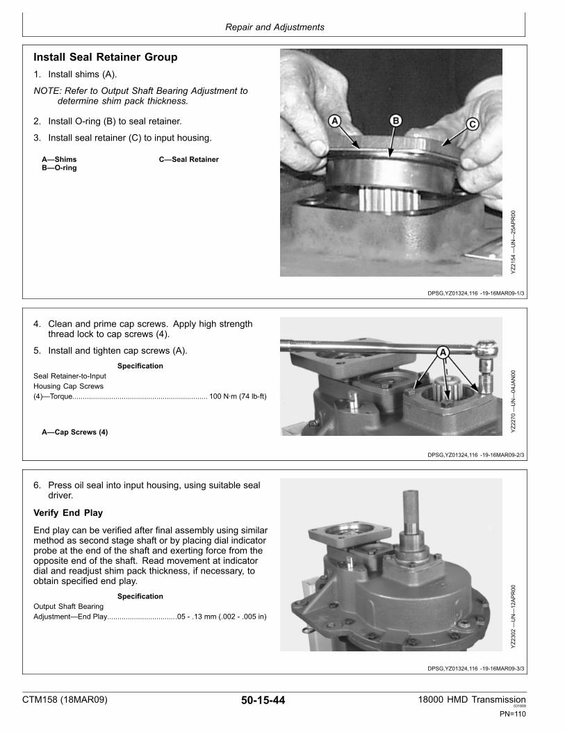
Repair and Adjustments
DPSG,YZ01324,116 1916MAR091/3
DPSG,YZ01324,116 1916MAR092/3
DPSG,YZ01324,116 1916MAR093/3
Install Seal Retainer Group1. Install shims (A).
NOTE: Refer to Output Shaft Bearing Adjustment todetermine shim pack thickness.
2. Install Oring (B) to seal retainer.
3. Install seal retainer (C) to input housing.
A—ShimsB—Oring
C—Seal Retainer
YZ2154—UN—25APR00
4. Clean and prime cap screws. Apply high strengththread lock to cap screws (4).
5. Install and tighten cap screws (A).Specification
Seal RetainertoInputHousing Cap Screws(4)—Torque.................................................................. 100 N∙m (74 lbft)
A—Cap Screws (4) YZ2270—UN—04JAN00
6. Press oil seal into input housing, using suitable sealdriver.
Verify End Play
End play can be verified after final assembly using similarmethod as second stage shaft or by placing dial indicatorprobe at the end of the shaft and exerting force from theopposite end of the shaft. Read movement at indicatordial and readjust shim pack thickness, if necessary, toobtain specified end play.
SpecificationOutput Shaft BearingAdjustment—End Play..................................05 .13 mm (.002 .005 in)
YZ2302—UN—12APR00
CTM158 (18MAR09) 501544 18000 HMD Transmission031809
PN=110
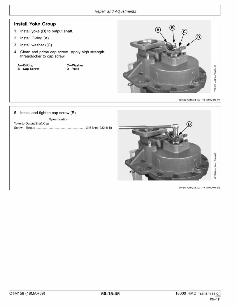
Repair and Adjustments
DPSG,YZ01324,103 1917MAR091/2
DPSG,YZ01324,103 1917MAR092/2
Install Yoke Group1. Install yoke (D) to output shaft.
2. Install Oring (A).
3. Install washer ((C).
4. Clean and prime cap screw. Apply high strengththreadlocker to cap screw.
A—ORingB—Cap Screw
C—WasherD—Yoke
YZ2301—UN—09NOV99
5. Install and tighten cap screw (B).Specification
YoketoOutput Shaft CapScrew—Torque........................................................... 315 N∙m (232 lbft)
YZ2266—UN—10JAN00
CTM158 (18MAR09) 501545 18000 HMD Transmission031809
PN=111
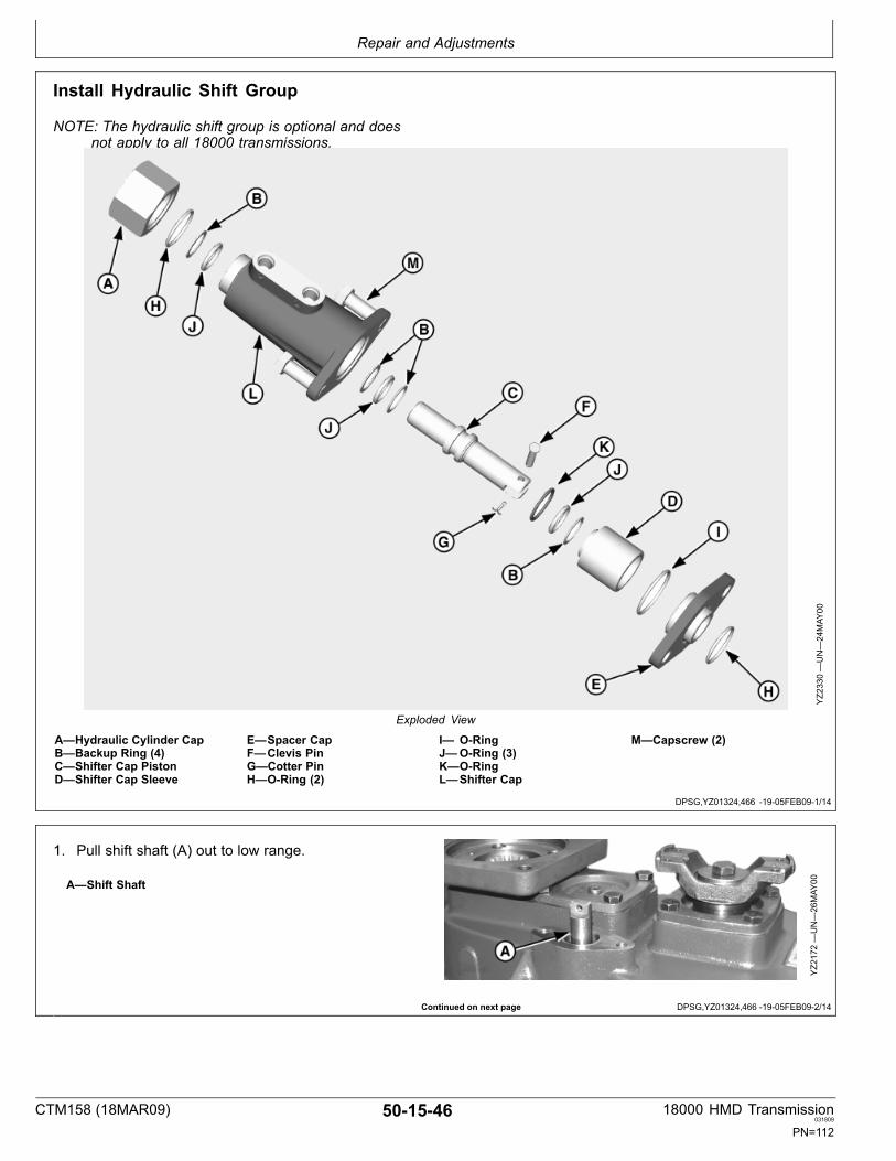
Repair and Adjustments
DPSG,YZ01324,466 1905FEB091/14
Continued on next page DPSG,YZ01324,466 1905FEB092/14
Install Hydraulic Shift Group
NOTE: The hydraulic shift group is optional and doesnot apply to all 18000 transmissions.
YZ2330—UN—24MAY
00
Exploded View
A—Hydraulic Cylinder CapB—Backup Ring (4)C—Shifter Cap PistonD—Shifter Cap Sleeve
E—Spacer CapF—Clevis PinG—Cotter PinH—ORing (2)
I— ORingJ—ORing (3)K—ORingL—Shifter Cap
M—Capscrew (2)
1. Pull shift shaft (A) out to low range.
A—Shift Shaft
YZ2172—UN—26MAY
00
CTM158 (18MAR09) 501546 18000 HMD Transmission031809
PN=112

Repair and Adjustments
DPSG,YZ01324,466 1905FEB093/14
DPSG,YZ01324,466 1905FEB094/14
Continued on next page DPSG,YZ01324,466 1905FEB095/14
2. Lubricate and install Orings (A & B) to spacer cap.
A—ORing B—ORing
YZ2171—UN—26MAY
00
3. Install spacer cap.
YZ2173—UN—26MAY
00
NOTE: Backup rings are concave on one side toaccommodate the oring.
4. Lubricate and install backup ring (A), Oring (B), andbackup ring (A), consecutively, to center groove ofshifter cap piston (C).
A—Backup Rings (2)B—ORing
C—Shifter Cap PistonYZ2164—UN—26MAY
00
CTM158 (18MAR09) 501547 18000 HMD Transmission031809
PN=113

Repair and Adjustments
DPSG,YZ01324,466 1905FEB096/14
DPSG,YZ01324,466 1905FEB097/14
Continued on next page DPSG,YZ01324,466 1905FEB098/14
5. Lubricate and install backup ring (A) and Oring (B) ingroove inside shifter cap sleeve (C).
A—Backup RingB—ORing
C—Shifter Cap Sleeve
YZ2163—UN—26MAY
00
6. Lubricate and install Oring (A) to outside groove ofshifter cap sleeve (B).
A—ORing B—Shifter Cap Sleeve
YZ2167—UN—26MAY
00
7. Install shifter cap sleeve (B) onto shifter cap piston (A).
A—Shifter Cap Piston B—Shifter Cap Sleeve
YZ2162—UN—26MAY
00
CTM158 (18MAR09) 501548 18000 HMD Transmission031809
PN=114

Repair and Adjustments
DPSG,YZ01324,466 1905FEB099/14
DPSG,YZ01324,466 1905FEB0910/14
Continued on next page DPSG,YZ01324,466 1905FEB0911/14
8. Install clevis (B) and cotter (C) pins to connect shifterassembly (A) to shift shaft (C).
A—Shifter AssemblyB—Clevis Pin
C—Cotter PinD—Shift Shaft
YZ2174—UN—26MAY
00
9. Lubricate and install Oring (A) and backup ring (B) ingroove inside shifter cap (C).
A—ORingB—Backup Ring
C—Shifter Cap
YZ2165—UN—30MAY
00
10. Lubricate and install Oring (A) to outside groove ofshifter cap (B).
A—ORing B—Groove of Shifter Cap
YZ2166—UN—26MAY
00
CTM158 (18MAR09) 501549 18000 HMD Transmission031809
PN=115
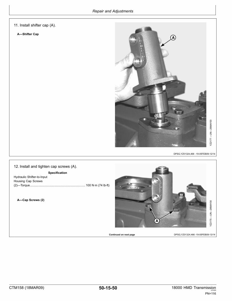
Repair and Adjustments
DPSG,YZ01324,466 1905FEB0912/14
Continued on next page DPSG,YZ01324,466 1905FEB0913/14
11. Install shifter cap (A).
A—Shifter Cap
YZ2177—UN—26MAY
00
12. Install and tighten cap screws (A).Specification
Hydraulic ShiftertoInputHousing Cap Screws(2)—Torque.................................................................. 100 N∙m (74 lbft)
A—Cap Screws (2)
YZ2175—UN—26MAY
00
CTM158 (18MAR09) 501550 18000 HMD Transmission031809
PN=116

Repair and Adjustments
DPSG,YZ01324,466 1905FEB0914/14
13. Install and tighten hydraulic cylinder cap (A).Specification
Hydraulic CylinderCaptoShifterCap—Torque.................................................................. 68 N∙m (50 lbft)
A—Hydraulic Cylinder Cap
YZ2176—UN—26MAY
00
CTM158 (18MAR09) 501551 18000 HMD Transmission031809
PN=117

Repair and Adjustments
DPSG,YZ01324,97 1917MAR091/1
Install Yoke Flange GroupNOTE: Optional Not applicable for all 18000
transmissions.
Skip this block if disc brake is used.
1. Install yoke flange (A).
2. Install Oring.
3. Install washer.
4. Clean and prime cap screw. Apply high strengththreadlocker to cap screw.
5. Install and tighten cap screw.Specification
Yoke FlangetoOutput Shaft CapScrew—Torque........................................................... 315 N∙m (232 lbft)
A—Yoke Flange
YZ2336—UN—07JAN00
CTM158 (18MAR09) 501552 18000 HMD Transmission031809
PN=118

Repair and Adjustments
Continued on next page DPSG,YZ01324,114 1917MAR091/2
Install Brake Disc And Companion Flange Group
NOTE: Optional Not applicable for all 18000transmissions.
YZ2334—UN—01NOV99
Exploded View
A—Cap Screw (8 Used)B—Disc BrakeC—Companion Flange
D—OringE—Yoke WasherF—Cap Screw
G—Clipped Washer (8 Used)H—Hex Nut (8 Used)I— Lock washer (8 Used)
CTM158 (18MAR09) 501553 18000 HMD Transmission031809
PN=119

Repair and Adjustments
DPSG,YZ01324,114 1917MAR092/2
1. Install brake bracket (H).
2. Install disc brake (G).
3. Install companion flange (F).
4. Install eight cap screws (E).
5. Install eight clipped washers.
6. Install eight lock washers.
7. Install and tighten 8 hex nuts (D).Specification
Brake DisctoCompanion Flange CapScrews—Torque............................................................. 48 N∙m (35 lbft)
8. Shim Oring.
• Determine difference between height of machineface of yoke and end of shaft to make it .010 tight.• Find difference and subtract .010.• Apply necessary shims.
9. Install Oring (C).
10. Install washer (B).
11. Clean and prime cap screws. Apply high strengththread lock to cap screw.
YZ2237—UN—12JU
N03
A—Cap ScrewB—WasherC—OringD—Hex Nuts (8 Used)
E—Cap Screws (8 Used)F—Companion FlangeG—Disc BrakeH—Brake Bracket
12. Install and tighten cap screw (A).Specification
Yoketooutput shaft capscrew—Torque........................................................... 315 N∙m (232 lbft)
CTM158 (18MAR09) 501554 18000 HMD Transmission031809
PN=120

Repair and Adjustments
DPSG,YZ01324,59 1916MAR091/4
Continued on next page DPSG,YZ01324,59 1916MAR092/4
Remove and Replace Caliper BrakeLining Assembly1. Loosen two adjustment locking nuts (C) enough to
allow clearance between the caliper assembly (B) andthe disc brake (A).
2. Remove one nut (E) securing caliper assembly tobracket (F).
3. Unscrew bolt until it clears the bracket (F).
4. Swing caliper assembly clockwise (B) away from discbrake.
YZ2227A
—UN—04JAN00
A—1Disc BrakeB—Caliper Assembly
C—Locking Nuts (2)D—Flat Spring
1Brake lining replacement kit is available from the manufacturer. Thekit includes lining assembly, spring, and instruction sheet.
5. Collapse, remove, and discard flat spring (D).
D—Flat Spring
YZ2348A
—UN—04JAN00
CTM158 (18MAR09) 501555 18000 HMD Transmission031809
PN=121

Repair and Adjustments
Continued on next page DPSG,YZ01324,59 1916MAR093/4
6. Remove and discard brake lining assembly (A) andreplace with new brake lining assembly1.
NOTE: It is recommended that a coating of“NEVERSEEZ”, an antiseize and lubricatingcompound, be applied to the interface of the sleeveand calipers before installation of the brake liningassemblies. Slide calipers back and forth on sleeveto insure that the lubricating compound has beenapplied to the bores of the calipers.
A—Brake Lining Assembly
YZ2347A
—UN—04JAN00
1Refer to brake lining replacement kit instruction sheet.
CTM158 (18MAR09) 501556 18000 HMD Transmission031809
PN=122
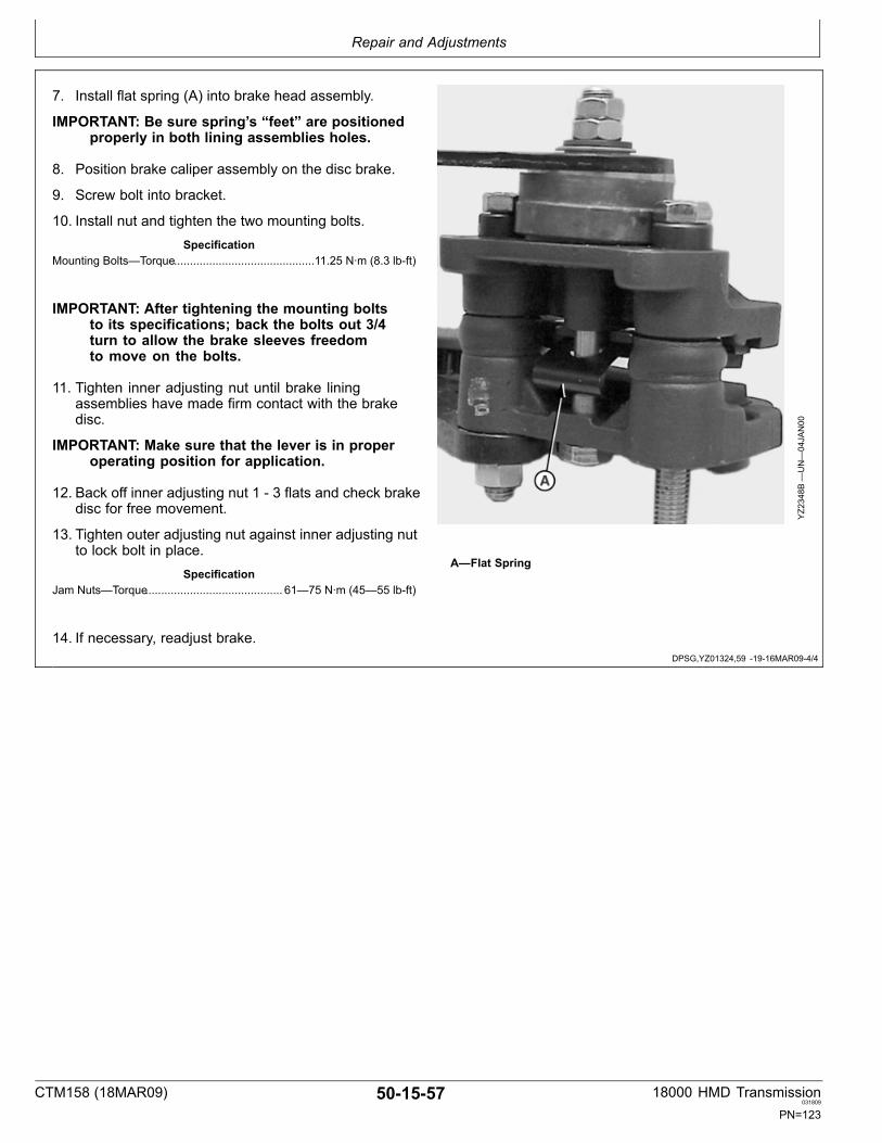
Repair and Adjustments
DPSG,YZ01324,59 1916MAR094/4
7. Install flat spring (A) into brake head assembly.
IMPORTANT: Be sure spring’s “feet” are positionedproperly in both lining assemblies holes.
8. Position brake caliper assembly on the disc brake.
9. Screw bolt into bracket.
10. Install nut and tighten the two mounting bolts.Specification
Mounting Bolts—Torque............................................11.25 N∙m (8.3 lbft)
IMPORTANT: After tightening the mounting boltsto its specifications; back the bolts out 3/4turn to allow the brake sleeves freedomto move on the bolts.
11. Tighten inner adjusting nut until brake liningassemblies have made firm contact with the brakedisc.
IMPORTANT: Make sure that the lever is in properoperating position for application.
12. Back off inner adjusting nut 1 3 flats and check brakedisc for free movement.
13. Tighten outer adjusting nut against inner adjusting nutto lock bolt in place.
SpecificationJam Nuts—Torque........................................... 61—75 N∙m (45—55 lbft)
14. If necessary, readjust brake.
YZ2348B
—UN—04JAN00
A—Flat Spring
CTM158 (18MAR09) 501557 18000 HMD Transmission031809
PN=123

Repair and Adjustments
Continued on next page DPSG,YZ01324,98 1916MAR091/5
Assemble and Install Lube Pump Group
YZ2320—UN—02NOV99
Exploded View
A—Pump SpringB—Pump Plunger
C—Pump Assembly1D—Gasket
E—Pipe PlugF—Cap Screw (6 Used)
G—Pump coverH—Pipe Plug
1Tab drive shown must align with input shaft.
CTM158 (18MAR09) 501558 18000 HMD Transmission031809
PN=124

Repair and Adjustments
DPSG,YZ01324,98 1916MAR092/5
Continued on next page DPSG,YZ01324,98 1916MAR093/5
1. Install pump spring (B).
2. Install pump plunger (A).
A—Pump Plunger B—Pump Spring
YZ2300—UN—09DEC99
3. Install gasket (B).
A—Pump Assembly B—Gasket
YZ2298—UN—09DEC99
CTM158 (18MAR09) 501559 18000 HMD Transmission031809
PN=125

Repair and Adjustments
Continued on next page DPSG,YZ01324,98 1916MAR094/5
4. Install pump assembly (A).
IMPORTANT: Make sure that tab of pump assemblyaligns with slot inside housing (A).
A(Left)—Tab of PumpAssembly
A (Bottom)—Slot InsideHousing
YZ2335—UN—10JAN00
CTM158 (18MAR09) 501560 18000 HMD Transmission031809
PN=126

Repair and Adjustments
DPSG,YZ01324,98 1916MAR095/5
IMPORTANT: Align pin (B) on pump cover with180° divot (C) on pump assembly.
5. Install pump cover (A) with arrow (C) facing towardscenter of housing.
IMPORTANT: The pump mounting cap screws andmounting holes must be clean, dry. ApplyPM63821 to the cap screws before attachmentof pump to output housing.
6. Apply PM63821 to Cap Screws.
7. Install and tighten cap screws (B).Specification
Lube PumptoOutputHousing Cap Screws(6)—Torque.......................................................................11 N∙m (8 lbft)
A—Pump CoverB—Cap Screws (6)
C—Arrow
YZ2339—UN—13JU
N03
B—Pin on Pump Cover C—180° Divot on PumpAssembly
YZ2297—UN—10JAN00
CTM158 (18MAR09) 501561 18000 HMD Transmission031809
PN=127

Repair and Adjustments
CTM158 (18MAR09) 501562 18000 HMD Transmission031809
PN=128

Group 20Transmission Operation
YZ07927,0000031 1927FEB091/1
DPSG,YZ01324,86 1916MAR091/1
Transmission Operation ListReferences to assist technician during machine diagnosisand repair.
• General Information
• Internal Lubrication• Lube Pump Operation• Gear Ratio Activation
General InformationThe 18000 transmission is a twospeed, hydrostaticmotordriven transmission that accepts a maximum inputpower of 200 SAE hp (149 kW). Hydrostatic motors acceptfluid under pressure from a hydrostatic pump attached toa power source. The motor converts the fluid energy intomechanical energy which is input to a transmission, suchas the 18000. The 18000 contributes added speed rangecapability to the drive system. Shifting from one rangeto another is accomplished by mechanical or hydraulicmeans.
CAUTION: Shifting can only be accomplishedwhen the vehicle is stopped and there is norotating motion in the transmission.
This transmission has three input options SAE “C”, SAE“B”, or “D” motor inputs. Output options include 5C, 6C,7C, or companion flange yokes. It also has an externalmounted disk parking brake option and a hydraulic shifteroption.
NOTE: All the options mentioned are not illustratedin this manual. Consult the manufacturer foradditional information, if necessary.
CTM158 (18MAR09) 50201 18000 HMD Transmission031809
PN=129

Transmission Operation
YZ01324,0000029 1916MAR091/1
Internal LubricationThe input splines, and 1st and 2nd stage bearings arelubricated by an internally plumbed reversing lube pump.
The first and second stage gears are splash lubed.
Output gears, bearings, and shift collar have constantcontact with sump oil.
CTM158 (18MAR09) 50202 18000 HMD Transmission031809
PN=130

Transmission Operation
YZ01324,0000026 1916MAR091/1
Lube Pump Operation
YZ2329B
—UN—15APR03
A—CoverB—Outer Gerotor RingC—Inner Gerotor
D—PlungerE—SpringF—Drive Tab
G—Floating PlateH—Outer SleeveI— Port Plate
J—Sleeve
The transmission has an internal fixeddisplacementgerotor lube pump. It is a bidirectional, positivedisplacement pump, in that, it creates flow in the samedirection, regardless of the direction of input rotation. Thegerotor pump is a variation of the internal gear pump. Thegerotor pump uses an inner and outer rotor, with roundedlobes for teeth, and no separator; whereas, the internalgear pump uses a spur gear inside a larger gear, whichis meshed on one side and divided by a crescentshapedseparator on the other side.
This particular lube pump is used solely to lubricate thebearings and input splines in the 1st and 2nd stageassemblies. The lube pump consists of the cover (A),pump assembly, plunger (D) and spring (E). The springand plunger keep the floating plate in contact with theinner and outer gerotors which forces the gerotors to keepin contact with the port plate to maintain s seal. The pumpassembly is comprised of the port plate (I), outer gerotorring (B), inner gerotor (C), outer sleeve (H), floating plate(G), and sleeve (J). The sleeve holds the alignment ofthe inner gerotor.
The port plate is machined so that when the driveshaft changes rotation, the port plate (I) rotates 180°,
maintaining the same direction of flow. The outer sleeve(H) has a drive tab (F) that limits the freeturning portplate’s rotation to 180°, in either direction, which maintainsconstant port positions, regardless of drive shaft rotation.
In operation, the pump assembly is connected to anddriven by the hydrostatic motor through the input shaft inthe first stage. Driven by the outer sleeve (I), the innergerotor (C) and outer gerotor ring (B) turn on the sleeve(J) inside the housing moving the same volume of oilwith every revolution of the pump. The inner gerotor andouter geroter ring have rounded lobes as teeth. The innergerotor has one less lobe than the outer gerotor ring toallow the inner lobes to slide over the outer lobes, makinga seal to prevent backup of oil. As the lobes of the innergerotor slide up and over the lobes of the outer gerotorring, oil is drawn in; creating pumping action. As the lobesfall into the ring’s cavities, the oil is expelled into the outletport. If the pressure exceeds the relief pressure, thespring (E) compresses, which increases pump clearance.That allows oil to bypass between the port plate and theouter sleeve, releasing the oil out of the pump.
CTM158 (18MAR09) 50203 18000 HMD Transmission031809
PN=131

Transmission Operation
YZ01324,0000027 1916MAR091/1
Gear Ratio Activation
YZ2316—UN—01NOV99
High gear is activated when the input shaft is driven,turning the second stage gear. The shift collar engages orlocks the higher gear to the output shaft.
Low gear is activated when the input shaft drives throughthe second stage gear and the shifter collar engages orlocks the low gear to the output shaft.
When the shift collar is in the center or detent position, itis in neutral and the output shaft is not turning. When thetransmission is in neutral, motion of the vehicle will not berestricted by the hydrostatic system. To prevent motion,the vehicle must be equipped with a parking mechanism
on the transmission or axle that is engaged when thetransmission is in neutral. Engagement of the parkingmechanism can be manual or automatic.
CAUTION: Shifting can only be accomplishedwhen the vehicle is stopped and there is norotating motion in the transmission.
IMPORTANT: To prevent motion, the vehicle mustbe equipped with a parking mechanism on thetransmission or axle that is engaged whenthe transmission is in neutral.
CTM158 (18MAR09) 50204 18000 HMD Transmission031809
PN=132

Group 25Brake Operation
YZ07927,0000032 1927FEB091/1
YZ01324,0000028 1916MAR091/1
Brake Operation ListReferences to assist technician during machine diagnosisand repair.
• Brake Operation
Brake OperationThe transmission has an optional externalmounteddisc parking brake (A). The caliper brake assembly(B) is a mechanically actuated brake designed forstatic or secondary applications. The brake is actuatedmechanically by rotating a ball and cam ramp lever (C).This advances the torque plates (D) towards the disc,compressing against the disc.
IMPORTANT: Parking brake only. Not to beused for servicing.
A—Disc BrakeB—Caliper Assembly1
C—LeverD—Torque Plates (Brake Lining
Assembly)
YZ2344—UN—08DEC99
Disc Brake & Caliper Brake Assembly
1Flat spring not shown.
CTM158 (18MAR09) 50251 18000 HMD Transmission031809
PN=133

Brake Operation
CTM158 (18MAR09) 50252 18000 HMD Transmission031809
PN=134
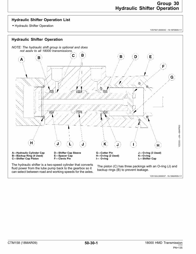
Group 30Hydraulic Shifter Operation
YZ07927,000003C 1916FEB091/1
YZ01324,0000037 1916MAR091/1
Hydraulic Shifter Operation List• Hydraulic Shifter Operation
Hydraulic Shifter Operation
NOTE: The hydraulic shift group is optional and doesnot apply to all 18000 transmissions.
YZ2333—UN—08APR03
A—Hydraulic Cylinder CapB—Backup Ring (4 Used)C—Shifter Cap Piston
D—Shifter Cap SleeveE—Spacer CapF—Clevis Pin
G—Cotter PinH—Oring (2 Used)I— Oring
J—Oring (3 Used)K—OringL—Shifter Cap
The hydraulic shifter is a twospeed cylinder that convertsfluid power from the lube pump back to the gearbox so itcan select between road and working speeds for the axles.
The piston (C) has three packings with an Oring (J) andbackup rings (B) to prevent leakage.
CTM158 (18MAR09) 50301 18000 HMD Transmission031809
PN=135

Hydraulic Shifter Operation
CTM158 (18MAR09) 50302 18000 HMD Transmission031809
PN=136

Group 35Troubleshooting
YZ07927,000003D 1927FEB091/1
YZ01324,0000031 1916MAR091/1
YZ01324,0000038 1916MAR091/1
Troubleshooting ListReferences to assist technician during machine diagnosisand repair.
• Transmission• Hydraulic Shifter
TransmissionNOTE: Diagnose malfunction charts are arranged from most probable and simplest to verify.
Symptom Problem Solution
Transmission Does Not Drive Park brake engaged Release park brake.
Twospeed gearbox failed Drain oil and check for metal particles.
Failed hydraulic pump Repair or replace pump.
Transmission Overheating Low oil level Add oil. Check system for leaks.
Dirty oil Drain and refill with clean oil, usingoil recommended by manufacturer.Check for source of contamination.
Oil level too high Establish proper oil level.
Internal component oil leakage Examine and test valves, cylinders,pumps, and so on, for external andinternal leaks. Repair or replace asnecessary.
Hydraulic ShifterNOTE: Diagnose malfunction charts are arranged from most probable and simplest to verify.
Symptom Problem Solution
Failure To Shift Cylinder leaks around the piston Replace Orings and backup rings(packing).
Scored cylinder walls Check for dirt and grit in oil.
Air in the cylinder Bleed air from cylinder.
Piston bent or broken Replace hydraulic shifter.
Creeping of Cylinder Internal leakage Replace Orings and backup rings.
Loose Mounting Loose or worn cap screws Tighten or replace cap screws.
CTM158 (18MAR09) 50351 18000 HMD Transmission031809
PN=137

Troubleshooting
CTM158 (18MAR09) 50352 18000 HMD Transmission031809
PN=138

Section 99SPECIAL TOOLS (DealerFabricated)
Contents
Page
Group 10—DEALERFABRICATED TOOLSDEALER FABRICATED TOOLSLIST ......................................................... 9910 1
Seal Driver................................................... 9910 1Seal Protector.............................................. 9910 2Bearing Driver.............................................. 9910 3Ball And Spring Sleeve................................ 9910 4
CTM158 (18MAR09) 991 18000 HMD Transmission031809
PN=1

Contents
CTM158 (18MAR09) 992 18000 HMD Transmission031809
PN=2

Group 10DEALERFABRICATED TOOLS
YZ07927,0000033 1927FEB091/1
YZ01324,0000044 1907MAY031/1
DEALER FABRICATED TOOLS LISTReferences to assist technician during machine diagnosisand repair.
• Seal Driver
• Seal Protector• Bearing Driver• Ball And Spring Sleeve
Seal Driver
YZ2181A
—UN—25JU
N03
A—Knurl
Used to press oil seal into input and output housing.
CTM158 (18MAR09) 99101 18000 HMD Transmission031809
PN=141

DEALERFABRICATED TOOLS
YZ01324,0000045 1915MAY031/1
Seal Protector
YZ2181B
—UN—25JU
N03
Placed over output shaft to protect oil seal when pressingseal into input and output housing.
CTM158 (18MAR09) 99102 18000 HMD Transmission031809
PN=142

DEALERFABRICATED TOOLS
YZ01324,0000046 1915MAY031/1
Bearing Driver
YZ2181F
—UN—25JU
N03
A—Knurl
Used to press bearings onto 3rd stage shaft.
CTM158 (18MAR09) 99103 18000 HMD Transmission031809
PN=143

DEALERFABRICATED TOOLS
YZ01324,0000048 1913JUN031/1
Ball And Spring Sleeve
YZ2181G
—UN—29JU
L03
NOTE: Detent spring and balls not used inhydraulic shifter option. Used to install detent balls and spring into 3rd stage shaft.
CTM158 (18MAR09) 99104 18000 HMD Transmission031809
PN=144

Index
Page
A
Adhesives and sealants....................................... 1030 1Assemble 1st Stage............................................. 501519Assemble 2nd Stage ........................................... 501521Assemble 3rd Stage ............................................ 501528
B
Bearing AdjustmentInput Shaft........................................................ 501541Output Shaft..................................................... 501543Second StageIntermediate Shaft ........................................ 501539
Brake Caliper Assembly Removal ....................... 5015 4Brake Operation .................................................. 5025 1
C
Cold Weather Operation...................................... 1025 2Component IDStandard Model................................................ 1010 1Standard Model With Options .......................... 1010 2
D
Disassemble 1st Stage........................................ 501519Disassemble 2nd Stage....................................... 501521Disassemble 3rd Stage ....................................... 501524
G
Gasket/Sealant ApplicationApply Sealant................................................... 1040 1Clean Surfaces ................................................ 1040 1
Gear Ratio Activation........................................... 5020 4General Information............................................. 5020 1General Repair Procedures................................. 1015 1General Specifications......................................... 5010 2
H
Hydraulic ShifterTroubleshooting ............................................... 5035 1
Hydraulic Shifter Operation ................................. 5030 1
I
Identification Plate ............................................... 1010 3Input Housing Installation .................................... 501535Install Bearing Retainer Group ............................ 501540Install Disc Brake/Companion FlangeGroup................................................................. 501553Install Hydraulic Motor Adapter Group ................ 501542Install Hydraulic Shift Group................................ 501546Install Lube Pump Group..................................... 501558
Page
Install Seal Retainer Group ................................. 501544Install Yoke Flange Group ................................... 501552Install Yoke Group ............................................... 501545Internal Lubrication.............................................. 5020 2
L
Lube Pump Operation ......................................... 5020 3LubricantMixing............................................................... 1025 1
M
Mixing lubricants.................................................. 1025 1
O
Oil CheckUp ....................................................... 1025 2Oil Fill................................................................... 1025 2Oil Seals .............................................................. 501538
P
Plugs.................................................................... 501538
R
Remove Bearing Retainer Group ........................ 501513Remove Disc Brake W/ Yoke/CompanionFlange................................................................ 5015 5Remove Hydraulic Motor AdapterGroup................................................................. 501512Remove Hydraulic shift........................................ 5015 6Remove Input Housing Group............................. 501514Remove Lube Pump............................................ 5015 1Remove Output Housing Group .......................... 501518Remove Seal Retainer Group ............................. 501511Remove Shaft Assembly Groups ........................ 501517Remove Yoke Group ........................................... 501510Replace Brake Lining .......................................... 501555
S
Safety, Towing ..................................................... 100513Safety, Vehicle Runaway Tag .............................. 1005 1Sealants and adhesives ...................................... 1030 1Shaft Assembly Group Installation ...................... 501533Shim Pack Bearing Retainer ............................. 5010 3Shim Pack Range................................................ 5010 3Specifications ...................................................... 5010 2Storage Preserving............................................ 1035 1Storage Restoring ............................................. 1035 1
T
Theory of OperationBrake Operation............................................... 5025 1
Continued on next page
CTM158 (18MAR09) Index1 18000 HMD Transmission031809
PN=1
Index
Page
Gear Ratio Activation ....................................... 5020 4General Information ......................................... 5020 1Hydraulic Shifter Operation.............................. 5030 1Internal Lubrication .......................................... 5020 2Lube Pump Operation...................................... 5020 3
Tooling ................................................................. 5005 1Torque Values...................................................... 5010 2Tapered Pipe Thread ....................................... 1020 3
TransmissionTroubleshooting ............................................... 5035 1
Page
Transmission Oil .................................................. 1025 2Transmission Oil Service..................................... 1025 2TroubleshootingHydraulic Shifter............................................... 5035 1Transmission.................................................... 5035 1
W
Weight Values...................................................... 5010 2
CTM158 (18MAR09) Index2 18000 HMD Transmission031809
PN=2