VERTICAL FLUE TERMINAL ASSEMBLY Ø 60/100 MM 7 … Vertic… · · 2015-11-09uk/ie installation...
12
UK/IE INSTALLATION INSTRUCTIONS FOR FLUE KIT VERTICAL FLUE TERMINAL ASSEMBLY Ø 60/100 MM 7 719 002 430 6 720 611 739-00.2O 3x 4x 2x FOR GAS CONDENSING APPLIANCES: GREENSTAR CDi COMBI/SYSTEM/REGULAR, GREENSTAR Si, GREENSTAR i JUNIOR/i SYSTEM, GREENSTAR Ri 6 720 611 739 GB (2009/09)
Transcript of VERTICAL FLUE TERMINAL ASSEMBLY Ø 60/100 MM 7 … Vertic… · · 2015-11-09uk/ie installation...

INSTALLATION INSTRUCTIONS FOR FLUE KIT
VERTICAL FLUE TERMINAL ASSEMBLY Ø 60/100 MM
7 719 002 430
6 720 611 739-00.2O
3x
4x
2x
FOR GAS CONDENSING APPLIANCES:GREENSTAR CDi COMBI/SYSTEM/REGULAR, GREENSTAR Si, GREENSTAR i JUNIOR/i SYSTEM, GREENSTAR Ri
UK/IE
6 72
0 61
1 73
9 G
B (
2009
/09)

CONTENTS
CONTENTS
1 Symbols and safety precautions . . . . . . . . . . . . 31.1 Explanation of symbols . . . . . . . . . . . . . . . 31.2 Safety precautions . . . . . . . . . . . . . . . . . . 3
2 installation regulations . . . . . . . . . . . . . . . . . . . . 4
3 Use . . . . . . . . . . . . . . . . . . . . . . . . . . . . . . . . . . . 53.1 General . . . . . . . . . . . . . . . . . . . . . . . . . . . 53.2 Standard specifications . . . . . . . . . . . . . . 5
4 Examples of installation of vertical flue with roof exit . . . . . . . . . . . . . . . . . . . . . . . . . . . . . . . . 64.1 Straight flue without bends . . . . . . . . . . . 64.2 Straight flue with two 45°-bends . . . . . . . 64.3 Straight flue with two 90°-bends . . . . . . . 7
5 Mounting . . . . . . . . . . . . . . . . . . . . . . . . . . . . . . . 85.1 Notes on fitting . . . . . . . . . . . . . . . . . . . . . 85.2 Roof-exit clearances . . . . . . . . . . . . . . . . . 85.2.1 Flat roof . . . . . . . . . . . . . . . . . . . . . . . . . . . 85.2.2 Inclined roof . . . . . . . . . . . . . . . . . . . . . . . 85.3 Fitting the flue . . . . . . . . . . . . . . . . . . . . . . 95.3.1 Adaptor . . . . . . . . . . . . . . . . . . . . . . . . . . . 95.3.2 Vertical Flue Terminal Assembly . . . . . . . 105.3.3 Clamp . . . . . . . . . . . . . . . . . . . . . . . . . . . 115.3.4 Fire stop plate . . . . . . . . . . . . . . . . . . . . . 11
6 720 611 739 (2009/09)2

SYMBOLS AND SAFETY PRECAUTIONS
1 SYMBOLS AND SAFETY PRECAUTIONS
1.1 EXPLANATION OF SYMBOLS
WARNING SYMBOLS
Signal words indicate the seriousness of the hazard in terms of the consequences of not following the safety instructions.
• NOTICE indicates possible damage to property or equipment, but where there is no risk of injury.
• CAUTION indicates possible injury.
• WARNING indicates possible severe injury.
• DANGER indicates possible risk to life.
IMPORTANT INFORMATION
ADDITIONAL SYMBOLS
1.2 SAFETY PRECAUTIONS
IF YOU SMELL GAS
B Do not smoke or strike matches.
B Do not turn electrical switches ON or OFF.
B Put out naked flames.
B Open doors and windows.
B Keep people away from the affected area.
B Turn off the control valve at the meter.
B Call your gas company.
-or-
B Call emergency number 0800 111 999.
IF YOU SMELL FUMES FROM THE APPLIANCE
B Switch off the appliance.
B Open windows and doors.
B Inform your heating engineer.
INSTALLATION INSTRUCTIONS
Please read these instructions carefully before starting installation. If you are in any doubt contact Worcester Technical Support.
These installation instructions must be read in conjunction with the appliance manual.
Please leave these instructions with the user or at the gas meter after installation or servicing.
Distance learning and training courses are available from Worcester, Bosch Group.
BENCHMARK
Please leave these instructions with the completed Benchmark Checklist (or a certificate confirming compliance with IS 813, EIRE only) with the owner after installation or servicing.
The Benchmark Checklist can be found in the back two pages of the appliance installation manual.
Safety instructions in this document are framed and identified by a warning triangle which is printed on a grey background.
Electrical hazards are identified by a lightning symbol surrounded by a warning triangle.
Notes contain important information in cases where there is no risk of personal injury or material losses and are identified by the symbol shown on the left. They are bordered by horizontal lines above and below the text.
Symbol Meaning
B a step in an action sequence
a reference to a related part in the docu-ment or to other related documents
• a list entry
– a list entry (second level)
Tab. 1
6 720 611 739 (2009/09) 3

INSTALLATION REGULATIONS
FITTING AND MODIFICATIONS
Fitting the flue system to the appliance must be carried out by a GAS SAFE registered, competent person in accordance with these installation instructions and the current Gas Safety Regulations (Installation and Use).
Flue systems must not be modified in any way other than as described in the fitting instructions. Any misuse or unauthorised modifications to the appliance, flue or associated components and systems will invalidate the warranty. The manufacturer accepts no liability arising from any such actions, excluding statutory rights.
B Position the flue terminal in such a way so that combustion products do not enter the building or cause a nuisance.
B Position the flue in such a way so the flue does not cause an obstruction.
B Ensure the flue terminal is not obstructed and combustion products can discharge without hindrance.
B Fit the flue according to the regulations and standards.
SERVICING
Advise the user to have the system serviced annually by a GAS SAFE registered, competent person using approved spares, to help maintain the economy, safety and reliability of the appliance.
The service engineer must complete the Service Record on the Benchmark Checklist after each service.
2 INSTALLATION REGULATIONS
Relevant regulations:
• Gas Safety Regulations 1998 (Installation and Use)
• Building Regulations
• Building Regulations (Northern Ireland)
• Building Standards (Scotland) (Consolidation)
• IS 813 (Eire)
• IGE “Gas Installation in Timber Frame Buildings”
• Any other local requirement
The relevant British Standards to be followed, include:
• BS5440:1Flues and ventilation for gas appliances of rated heating not exceeding 70 kW (net): Flues
• BS5440:2Flues and ventilation for gas appliances of rated heating not exceeding 70 kW (net): Air Supply
• BS7698Installation of gas fired appliances of rated input up to 70 kW (net)
If no specific instruction is given, refer to the British Standard Codes of Practice.
Current Gas Safety Regulations (Installation and Use):Failure to install flue systems correctly could lead to prosecution. All flue systems and associated components must be installed by a GAS SAFE registered, competent person in accordance with the following regulations.
6 720 611 739 (2009/09)4
USE
3 USE
3.1 GENERALThe installation of a gas condensing appliance must be in accordance with the relevant British Standard, the relevant Building Regulations and any local rules.
The surface temperature of the flue is below 85 °C. Therefore the distance from a combustible building material is kept to a minimum of 5 mm.
FLUEING TO C33:
The flue gas accessory is part of CE approval when discharging flue gas according to C33. For this reason, only the original flue gas accessories may be used.
All illustration dimensions are shown in mm unless stated otherwise.
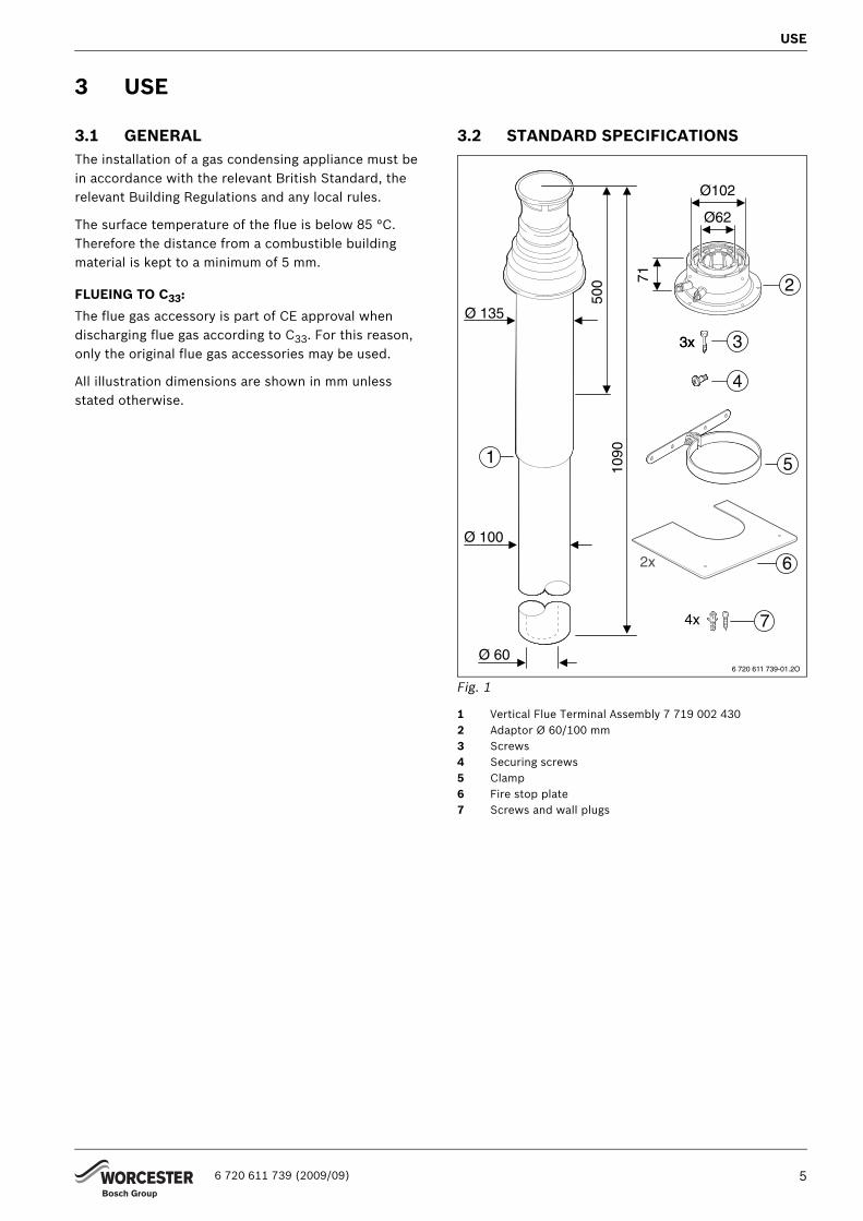
3.2 STANDARD SPECIFICATIONS
Fig. 1
1 Vertical Flue Terminal Assembly 7 719 002 430 2 Adaptor Ø 60/100 mm3 Screws4 Securing screws5 Clamp6 Fire stop plate7 Screws and wall plugs
3x
4x
6 720 611 739-01.2O
5
6
7
1
Ø 60
Ø 100
Ø 135
500
1090
2
Ø62
71
Ø102
3x 3
4
2x
6 720 611 739 (2009/09) 5

EXAMPLES OF INSTALLATION OF VERTICAL FLUE WITH ROOF EXIT
4 EXAMPLES OF INSTALLATION OF VERTICAL FLUE WITH ROOF EXIT
4.1 STRAIGHT FLUE WITHOUT BENDS
Fig. 2
1 Vertical Flue Terminal Assembly2 Adaptor Ø 60/100 mmA Extension
4.2 STRAIGHT FLUE WITH TWO45°-BENDS
Fig. 3
1 Vertical Flue Terminal Assembly2 Adaptor Ø 60/100 mmA Extension B 45° bend
Appliances Lmax
GREENSTAR 24i/28i JUNIORGREENSTAR 25Si/30SiGREENSTAR 12i/15i/18i/24i SYSTEMGREENSTAR 12 Ri/15 Ri/18 Ri/24 Ri
6.4 m
GREENSTAR 27CDi 11.5 m
GREENSTAR 30CDiGREENSTAR 37CDi
8.0 m
GREENSTAR 40CDi REGULARGREENSTAR 42CDi
7.5 m
GREENSTAR 30CDi SYSTEM/REGULAR 9.4 m
Tab. 2
≤ 99
0
≤ 10
90
L
6 720 611 739-04.2O
Ø 100
Ø 135
500
≤ 99
0
A
A
2
1
Appliances Lmax
GREENSTAR 24i/28i JUNIORGREENSTAR 25Si/30SiGREENSTAR 12i/15i/18i/24i SYSTEMGREENSTAR 12 Ri/15 Ri/18 Ri/24 Ri
4.4 m
GREENSTAR 27CDi 10.0 m
GREENSTAR 30CDiGREENSTAR 37CDi
6.5 m
GREENSTAR 40CDi REGULARGREENSTAR 42CDi
6.0 m
GREENSTAR 30CDi SYSTEM/REGULAR 7.9 m
Tab. 3
85
6 720 611 739-05.2O
LØ 100
Ø 13550
0
≤ 10
90
≤ 99
0
≤ 99
0
A
A
BB
2
1
6 720 611 739 (2009/09)6

EXAMPLES OF INSTALLATION OF VERTICAL FLUE WITH ROOF EXIT
4.3 STRAIGHT FLUE WITH TWO 90°-BENDS
Fig. 4
Key to Fig. 4, 5 and 6:
1 Vertical Flue Terminal Assembly2 Adaptor Ø 60/100 mmA Extension C 90° bend
Fig. 5
Fig. 6
Appliances Lmax
GREENSTAR 24i/28i JUNIORGREENSTAR 25Si/30SiGREENSTAR 12i/15i/18i/24i SYSTEMGREENSTAR 12 Ri/15 Ri/18 Ri/24 Ri
2.4 m
GREENSTAR 27CDi 8.5 m
GREENSTAR 30CDiGREENSTAR 37CDi
5.0 m
GREENSTAR 40CDi REGULARGREENSTAR 42CDi
4.5 m
GREENSTAR 30CDi SYSTEM/REGULAR 6.4 m
Tab. 4
173
6 720 611 739-06.2O
≤ 10
90
500
Ø 135
Ø 100
≤ 99
0 L
≤ 99
0
A
C
C
A
2
1
6 720 611 739-07.2O
≤ 10
90
≤ 99
0
≤ 99
0
≤ 990
Ø 100
Ø 135500
L
A
C
C
A
2
1
L
6 720 611 739-08.2O
≤ 99
0
≤ 99
0
≤ 990
≤ 99
0
Ø 100
Ø 135500
≤ 10
90
A
C
C
A
A
2
1
6 720 611 739 (2009/09) 7

MOUNTING
5 MOUNTING
5.1 NOTES ON FITTING• The vertical flue (7 719 002 430) can be extended at
any point between the adaptor [2] and the flue terminal assembly [1] using the flue kits “bend 45°”, “bend 90°” or “extension”.
• For flue pipe maximum and equivalent lengths with the usage of bends refer to the installation instructions with the appliance.
• Horizontal flue sections should be fitted with an incline of 3° (= 5,2 %, 5,2 cm per meter) in the direction of flow of the flue gases.
5.2 ROOF-EXIT CLEARANCES
5.2.1 FLAT ROOF
Fig. 7
5.2.2 INCLINED ROOF
Fig. 8
Combustible building material
Non-combustible building material
X ≥ 1500 mm ≥ 500 mm
Tab. 5
135
≥ 30
0
X
6 720 611 739-13.1O
≥ 400
≤ 45°
6 720 611 739-14.1O
6 720 611 739 (2009/09)8

MOUNTING
5.3 FITTING THE FLUE
5.3.1 ADAPTOR
B Grease the flue-pipe seal of the adaptor with solvent-free grease (e.g. Vaseline).
B Unscrew the screws around the flue connection on the air box.
Fig. 9
B Align adaptor so that the flue testing points are facing forwards.
B Fix adaptor [2] in place using screws [3] of 7 719 002 430.
Fig. 10
2 Adaptor3 Screw
B Connect rest of flue (7 719 002 430, “bend 45°”, “bend 90°”, “extension”) to adaptor [2] and secure with screw [4].
Fig. 11
2 Adaptor4 Securing screw
� ��� ��� �������
3
26 720 617 258-02.1O
O2
CO2
26 720 617 258-05.1O
O2
CO2
4
6 720 611 739 (2009/09) 9

MOUNTING
5.3.2 VERTICAL FLUE TERMINAL ASSEMBLY
B Determine the length LV of the air pipe.
Fig. 12
1 Vertical Flue Terminal Assembly
B Cut off the air pipe at a right angle, deburr the cut edges and clean.
B Determinate the length LA = LV + 50 mm of the flue pipe.
Fig. 13
1 Vertical Flue Terminal Assembly
B Cut off the flue pipe at a right angle, deburr the cut edges and clean.
B Lightly grease the seals on the sleeves with a solvent-free grease (e.g. Vaseline).
B Fit pipes together by twisting and pushing home as far as possible secure with screw.
Fig. 14
1 Vertical Flue Terminal Assembly
LV
6 720 611 438-13.2O
1
LA
LV
6 720 610 703-10.2O
1
6 720 611 438-14.2O
1.
2.
1
6 720 611 739 (2009/09)10
MOUNTING
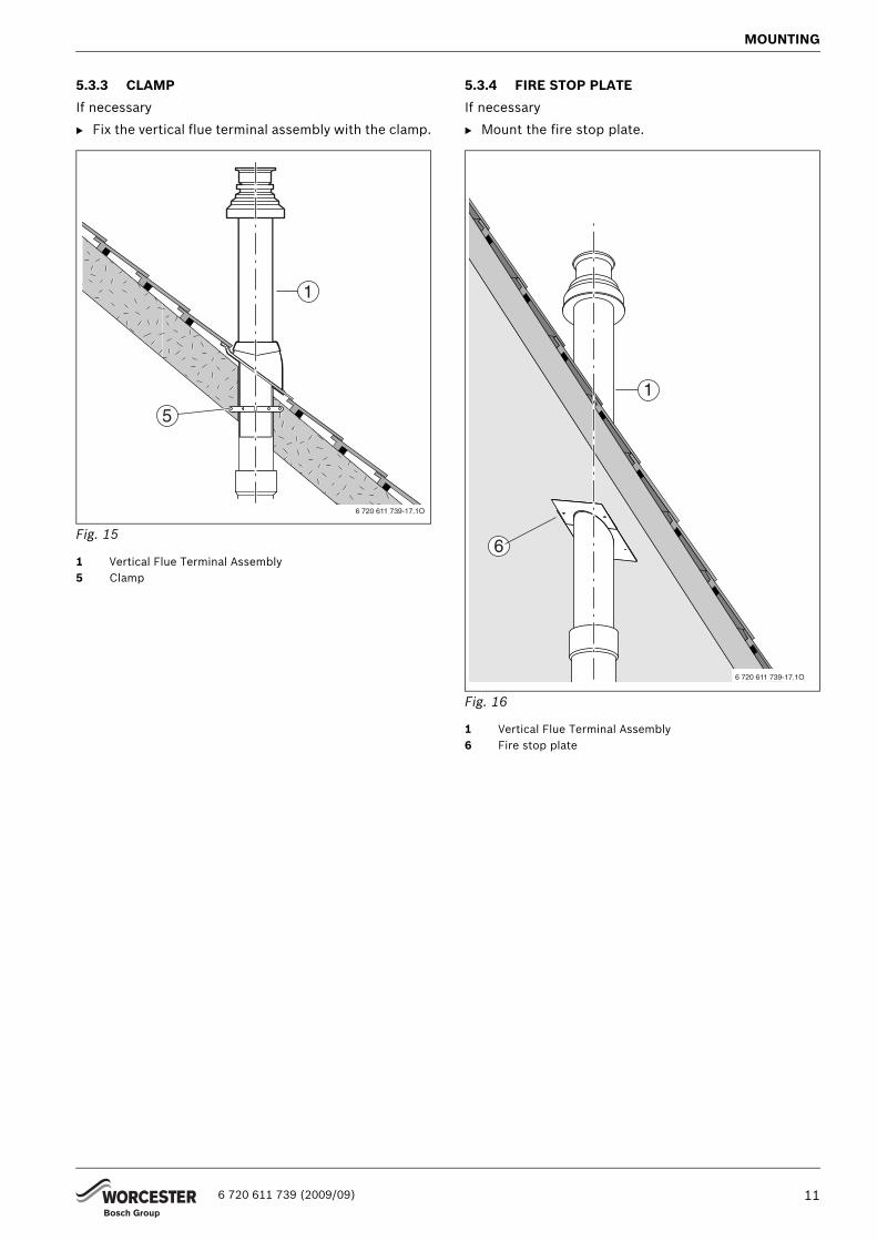
5.3.3 CLAMP
If necessary
B Fix the vertical flue terminal assembly with the clamp.
Fig. 15
1 Vertical Flue Terminal Assembly5 Clamp
5.3.4 FIRE STOP PLATE
If necessary
B Mount the fire stop plate.
Fig. 16
1 Vertical Flue Terminal Assembly6 Fire stop plate
6 720 611 739-17.1O
1
5
6 720 611 739-17.1O
1
6
6 720 611 739 (2009/09) 11

Wo
Co
Te
Wowo
6 7
1
6
1
6
6
0
k
rcester, Bosch Group
tswold Way, Warndon, Worcester WR4 9SW.
l. 01905 754624 Fax. 01905 754619
rcester, Bosch Group is a brand name of Bosch Thermotechnology Ltd.rcester-bosch.co.uk
CONTACT INFORMATION
WORCESTER, BOSCH GROUP:
TECHNICAL: 08705 26624
SERVICE: 08457 25620
SPARES: 01905 75257
LITERATURE: 01905 75255
TRAINING: 01905 75252
SALES: 01905 75264
WEBSITE: worcester-bosch.co.u
20 611 739