
Vertex Laser 5 & Laser 5
30
© HAGLÖF SWEDEN AB 2013 Vertex Laser 5 & Laser 5 User Manual English
Transcript of Vertex Laser 5 & Laser 5

© HAGLÖF SWEDEN AB 2013
Vertex Laser 5 & Laser 5User Manual
English
© HAGLÖF SWEDEN AB 2013
Haglöf Sweden®
Haglöf Sweden AB is a family owned company with long tradition of product development and manufacturing of measuring solutions for professional forest work. Today, Haglöf Sweden manufacture and sell the most complete product range for cruising and inventory work.
A profound know-how in workshop production technique has grown to encompass our state-of-the-art manufacturing of electronic instruments and field software.
There are over 200 companies representing the Haglöf Sweden brand name around the world. Being a manufacturer with self-owned and -run production facilities, the entire production process is under our control. This ensures availability and reliable deliveries for you, as well as prompt service and support when you need it, no matter where in the world you are located.
Every operator of a Haglöf Sweden product is a member of our innovation team. We mark our resources for product development and maintain the flexibility of a small organization.
Many Haglöf Sweden instruments are used also outside the forestry industry, such as in building dimensions and utility industry, for road construction, in police work, gardening, power line survey, archaeology, geology and for wildlife mana-gement.
Postal: Box 28, SE-882 21 Långsele.
Visit: Klockargatan 8, SE-882 30 Långsele.
Tel +46 620 255 80.
Fax +46 620 205 81.
www.haglofsweden.com
© HAGLÖF SWEDEN AB 2013 | iii
Contents1 Overview 1
Vertex Laser VL5 2
Laser L5 2
Transponder T3 3
2 System Description 4
Menu Schedule 4
Function 4
Buttons 4
ON 4
ARROW BUTTONS 4
DME 4
SEND 4
OFF (DME + SEND) 4
AIM POINT SIGHT 5
BATTERY 5
DISTANCE MEASURING 5
LASER 5
ULTRASOUND 5
HEIGHTS 5
ONE SHOT 5
THREE POINTS HEIGHT MEASURING 5
TWO POINTS HEIGHT MEASURING 5
ANGLE 6
HAZARD TREES 6
DELTA HEIGHT 6
3 Operating Procedure 7
SETUP – SETTINGS 7
METRIC/FEET: 7
DEG/GRAD/% 7
P OFFSET: 7
TRP HGT: 7
EYE HGT: 7
M DIST: 7
LASER MODE: 7
BAF: 8
iv | © HAGLÖF SWEDEN AB 2013
DATA OUTPUT: 8
SAVE DATA IN MEMORY: 8
CONTRAST – SETTINGS OF DISPLAY CONTRAST 8
CALIBRATE – CALIBRATING THE ULTRASOUND 8
DISTANCE MEASURING WITH ULTRASOUND 8
TRANSPONDER T3 9
ADAPTER 9
PLOT CENTRE STAFF 9
BAF – BASAL AREA FUNCTION 9
BAF WITH LASER 9
HGT VERTEX 10
2-POINT MEASURING WITH ULTRASOUND 10
2-POINT MEASURING WITH MANUAL DISTANCE 10
1-POINT MEASURING FROM THE HORIZONTAL LINE 10
HEIGHT 1PL 11
1-POINT MEASURING WITH LASER 11
HEIGHT 2PL 11
2 POINT MEASURING WITH LASER 11
HT 2PL REF 11
2-POINT MEASURING WTH LASER AND POINT OF REFERENCE11
HEIGHT 3PL 12
3-POINT MEASURING WITH LASER 12
TREE LIMIT 12
BORDER TREES/DANGEROUS TREES 12
OBJECT HGT – MEASURING THE OBJECT 13
MANUAL - MANUAL HEIGHT 13
MEAS – TO MEASURE HEIGHTS 13
LASER 13
HEIGHT 1PL 13
HT 2PL REF AND HGT VERTEX 13
HGT VERTEX – ULTRASOUND 13
HGT VERTEX – MANUAL DISTANCE 14
HT 2PL REF – LASER 14
TREE HGT – MEASURING THE TREE HEIGHT 14
DELTA HGT 14
DELTA HEIGHT FUNCTION 14
ANGLE 15
MEASURING OF ANGLES/INCLINATION 15
HORIZONTAL DISTANCE WITH ULTRA SOUND 15
BLUETOOTH – COMMUNICATION 16
ACTIVATE BLUETOOTH 16
IR – COMMUNICATION 16
MEM FUNCS - MEMORY FUNCTIONS 16
SAFETY AND OPERATION PRECAUTIONS 17
CARE, STORAGE AND MAINTENANCE 17
NOTES ON BATTERIES 17
4 Troubleshooting 18
Troubleshooting Laser 18
Troubleshooting Ultrasound 19
WARRANTY AND SERVICE INFORMATION 20
IMPORTANT ISSUES: 20
5 Technical Specification 21
DATA FORMAT 21
HAGLOF 21
NMEA 22
NMEA EXTENDED 22
Physical 23
Power 23
User interface 23
Memory 23
Height 23
Vertical Angle 23
Laser 24
Ultrasound 24
Transponder T3 24
Other 24
DECLARATION OF CONFORMITY 25
Version: 1.2 User ManualRevised: 2013-10-16 10:02 Vertex Laser 5 - (VL5) & Laser 5 - (L5)
© HAGLÖF SWEDEN AB 2013 | 1
1 Overview
HAGLÖF SWEDEN’S HIGH QUALITY MEASURING INSTRUMENTS ARE USEFUL WHEN YOU NEED RELIABLE, FAST AND ACCURATE DISTANCE-, HEIGHT- AND ANGLE- MEASUREMENT RESULTS.
The Vertex Laser VL5 instrument uses laser or ultrasound technology to present distance measurements and a high quality tilt sensor to measure angles. The different measuring methods - ultrasound and laser - can be used individually or com-bined. Choice of measuring method and technology is up to the operator. In general, the ultrasound method offers precise results for shorter distances and in dense vegetation, and the laser method allows for long distance measuring and instant presentation of measurement results without having to use a transponder. The L5 instrument includes laser technique only and is especially suitable for long distance measuring and work in utility industry etc.
The Vertex ultrasound method uses ultrasonic signals to obtain the exact distance from the measuring instrument to the T3 transponder. The height is calculated trigonometrically with the measured results on distance and angle. The T3 Tran-sponder works both in a 60º mode for direct height measuring, for example pinned directly to a tree stem; or in a 360º mode when set onto the plot centre staff (art no CPIN), an ideal way to work when measuring in circular sample plots with the Vertex Ultrasound measuring technique. The T3 can also be used as a reflector and a visible target point when using the laser measuring method in the Vertex Laser.
The ultrasound measuring technology works also when and if the target is not visible, as in completely or partially cov-ered. Ultrasound methodology is useful when working in circular sample plots, and if the reference point (centre of plot) is covered by branches, trees and bushes. When measuring the angle to the reference point, the horizontal distance can be presented.
The laser in the Vertex Laser VL5 is of optimal quality, very accurate and with extensive measuring range. It emits invis-ible, eye safe infrared energy pulses that reflect off the selected target back to its optical receiver. The exact distance is calculated by comparing the return time to the speed-of-light constant and presented in the instrument display. The ability of a laser sensor to measure to a target depends on the target’s reflectance and any interference between the sensor and the target, such as dust, fog, foliage or other. Reflectance is determined by color, opacity, distance and the reflection angle as well as the density of any ambient interference between the sensor and the target. A lighter target is more reflective than a darker one and thick dust will reduce the signal strength more than light dust. An adjustable laser filter allows for flexible measuring, where you can select to measure the closest object, the farthest object or the object that submits the strongest signal.
Working with factor gauges (“relaskopes”) or prism sometimes offers difficulties if the underbrush is too thick. Poor sighting will prevent a correct diameter evaluation. With the Vertex Laser instrument’s built in BAF function (Basal Area Function), the minimum tree diameter for trees to be included in the plot can be featured, when measuring the distance from the tree to the reference point/plot centre, using the Vertex ultrasound method.
The VL5 and L5 instruments have built-in rechargeable battery that can be charged in PC, car, or with ac/dc adapter.
Different instrument configurations ensure best possible efficiency. For tree inventory and sample plot measuring, the VL5 Vertex Laser with functions to calculate mean height in a stand is recommended. If working with power line planning and control, the L5 Laser, capable to measure long distances and that quickly can tell whether a border tree can cause danger if falling over a power line is a suitable model. On paper and pulp industries to measure timber stack volumes, the VL5 can be special ordered and the firmware modified.
Data on heights, distances and angles can be transferred through a built-in Bluetooth or infrared transmitter to computer caliper, PC or handheld, for storage and further processing. The sight has a 1x magnification which simplifies identifica-tion of individual objects.
6
1
7
89
10
11
12
13
14
15
2 3 4 5
User Manual Version: 1.2Vertex Laser 5 - (VL5) & Laser 5 - (L5) Revised: 2013-10-16 10:02
2 | © HAGLÖF SWEDEN AB 2013
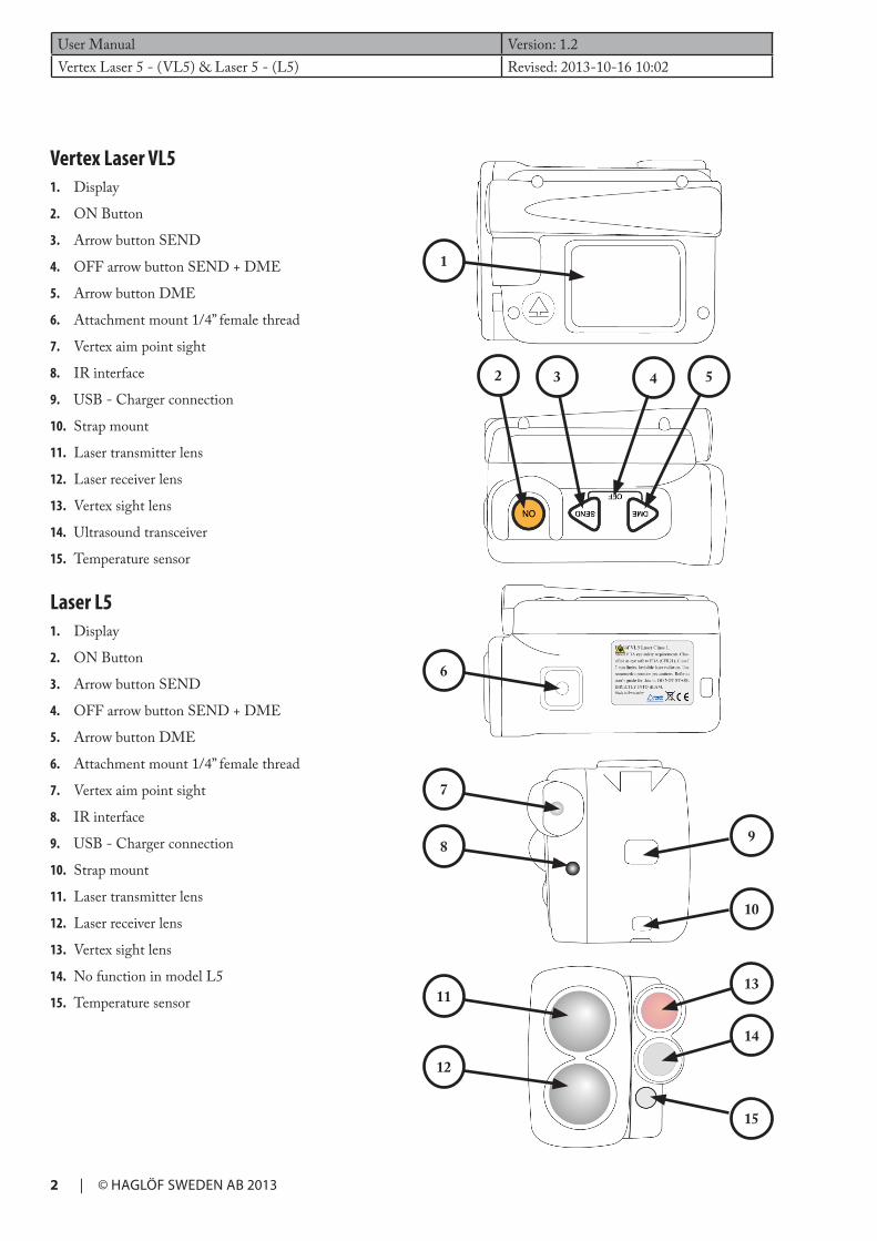
Vertex Laser VL5 1. Display
2. ON Button
3. Arrow button SEND
4. OFF arrow button SEND + DME
5. Arrow button DME
6. Attachment mount 1/4” female thread
7. Vertex aim point sight
8. IR interface
9. USB - Charger connection
10. Strap mount
11. Laser transmitter lens
12. Laser receiver lens
13. Vertex sight lens
14. Ultrasound transceiver
15. Temperature sensor
Laser L5 1. Display
2. ON Button
3. Arrow button SEND
4. OFF arrow button SEND + DME
5. Arrow button DME
6. Attachment mount 1/4” female thread
7. Vertex aim point sight
8. IR interface
9. USB - Charger connection
10. Strap mount
11. Laser transmitter lens
12. Laser receiver lens
13. Vertex sight lens
14. No function in model L5
15. Temperature sensor

2
3
4
5
1
Version: 1.2 User ManualRevised: 2013-10-16 10:02 Vertex Laser 5 - (VL5) & Laser 5 - (L5)
© HAGLÖF SWEDEN AB 2013 | 3
Transponder T3(Model VL5)
1. Ultrasound transceiver
2. Transponder housing
3. Battery cover
4. Adapter
5. Plot Center Staff
User Manual Version: 1.2Vertex Laser 5 - (VL5) & Laser 5 - (L5) Revised: 2013-10-16 10:02
4 | © HAGLÖF SWEDEN AB 2013
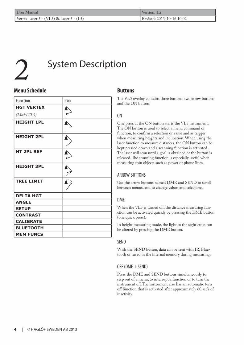
ButtonsThe VL5 overlay contains three buttons: two arrow buttons and the ON button.
ONOne press at the ON button starts the VL5 instrument. The ON button is used to select a menu command or function, to confirm a selection or value and as trigger when measuring heights and inclination. When using the laser function to measure distances, the ON button can be kept pressed down and a scanning function is activated. The laser will scan until a goal is obtained or the button is released. The scanning function is especially useful when measuring thin objects such as power or phone lines.
ARROW BUTTONSUse the arrow buttons named DME and SEND to scroll between menus, and to change values and selections.
DMEWhen the VL5 is turned off, the distance measuring fun-ction can be activated quickly by pressing the DME button (one quick press).
In height measuring mode, the light in the sight cross can be altered by pressing the DME button.
SENDWith the SEND button, data can be sent with IR, Blue-tooth or saved in the internal memory during measuring.
OFF (DME + SEND)Press the DME and SEND buttons simultaneously to step out of a menu, to interrupt a function or to turn the instrument off. The instrument also has an automatic turn off function that is activated after approximately 60 sec’s of inactivity.
Menu Schedule
Function IconHGT VERTEX
(Model VL5)
HEIGHT 1PL
HEIGHT 2PL
HT 2PL REF
HEIGHT 3PL
TREE LIMIT
DELTA HGTANGLESETUPCONTRASTCALIBRATEBLUETOOTHMEM FUNCS
2 System Description

Version: 1.2 User ManualRevised: 2013-10-16 10:02 Vertex Laser 5 - (VL5) & Laser 5 - (L5)
© HAGLÖF SWEDEN AB 2013 | 5
ULTRASOUNDUltrasound only in model VL5. Together with the T3 transponder, ultrasound can be used to measure the dis-tance to a plot centre and to obtain sample plot radius. You can work with the BAF Basal Area Function to determine if a tree is to be included in a sample plot study. Ultrasound allows the user to work also in dense forests which is a big advantage compared to other methods.
HEIGHTSThe Vertex Laser instrument offers different measuring methods for accurate height measuring:
ONE SHOTThe distance and the angle to an optio-nal part of the object are measured with laser.
To work with the one-shot method, the user has to be positioned on the same level- horizontal level - as the bottom of
the object to measure. Eye height -EYE.HGT - needs to be set in the settings menu.
THREE POINTS HEIGHT MEASURINGThe distance and the angle to an op-tional part of the object are measured with laser. The angle – inclination - is measured at the lowest (bottom) and at the highest (top) part of the object.
TWO POINTS HEIGHT MEASURINGThe distance and the angle to a reference point are measured with laser or ultra-sound and a transponder/target. The top angle is measured.
TWO POINTS LASER HEIGHT The distance and the angle to the bot-tom and to the top are measured with laser. This method is ideal for leaning objects.
AIM POINT SIGHTThe VL5 has a high intensive red aim point sight. The sight has no magnification, this to simplify identification of close-by objects. The intensity of the color/light in the sight can be adjusted by the operator during all measuring modes by pres-sing the DME button. There are a total of seven (7) steps for sight intensity/contrast.
BATTERYThe instrument has a built-in Li-Ion battery. The display includes a battery symbol that shows the battery status in four (4) steps (100%, 75%, 50%, 0%). Charge the battery by connecting the charging cable to the contact placed on the side of the VL5/L5 instrument. The battery symbol will change during charging and the charge will automatically
stop when the battery is fully charged. When charging, the instrument can-not be turned off. A full charge of an empty battery takes approx. 3.5 hours. Change of battery if necessary is made by authorized service stations only. A fully charged battery will last for ap-prox. 9000 measuring operations.
DISTANCE MEASURINGThere are two methods to measure distances in the VL5: using laser or using ultrasound. Which of these two met-hods that should be used for a particular measuring opera-tion is determined by different factors as what the terrain looks like, but also factors such as current weather condi-tions can be of importance. The laser function is often used to measure heights, border trees, delta height and to mea-sure long distances in open terrain. In combination with the T3 transponder, ultrasound measuring can be made in circular sample plots and to measure shorter distances in dense terrain with thick vegetation. For the L5 model, note that only descriptions on the laser method are valid.
LASERLaser can be used to measure tree heights, to determine hazard trees, to obtain delta height and to measure long range distances. Laser can also be used for the BAF fun-ction, even though ultrasound (VL5) may be more com-mon to use.

User Manual Version: 1.2Vertex Laser 5 - (VL5) & Laser 5 - (L5) Revised: 2013-10-16 10:02
6 | © HAGLÖF SWEDEN AB 2013
ANGLE
Angle measuring can be used to measure inclination in slopes.
HAZARD TREES
The Tree limit function is used to calculate hazard trees standing close to power lines, railroads, buildings etc.
The Tree limit function will calculate and give an estimate of the risk that the tree can hit the power line or the road in case of breakage.
DELTA HEIGHT
The Delta Height Function is used to calculate the height difference of a point at an imagined straight line between two fixed positions, and a third point, for example at a power line, where the line sag is closest to the ground.

Version: 1.2 User ManualRevised: 2013-10-16 10:02 Vertex Laser 5 - (VL5) & Laser 5 - (L5)
© HAGLÖF SWEDEN AB 2013 | 7
SETUP – SETTINGSIn the SETUP menu, all settings are made to measure heights, distances and angles. Also settings for data format to send data and if to save data in the internal memory in the instrument.
1. Press ON to activate the instrument.
2. Select SETUP and press ON to confirm your selec-tion.
3. Use the DME and SEND to change values and set-tings. Press ON to go to the next field. Settings are saved when you have stepped through all fields. To quit, press DME and SEND simultaneously.
METRIC/FEET: Select if to use metric or feet for heights and distances.
DEG/GRAD/%Select unit for inclination/angles as DEG (degrees 0…360), GRAD (grades 0…400) or % (percentage).
P OFFSET:
The Pivot offset refers to the distance from the front of the instrument to an imagined point where the extension of the aiming line from the transponder and the top of the tree coincide.
The point is located behind the neck of the instrument operator. The Pivot offset should in normal cases be set to approx. 0,3m/1.0feet.
Since the VL5 instrument presumes that the transponder is placed right under the required height of the measuring
3 Operating Procedure
object, half of the diameter measurement of a tree or other object should be added to the Pivot offset to compensate for the tapering of the tree. When measuring tree heights, a suggested solution is to add half of the mean diameter in the area where you are currently measuring.
TRP HGT:(Onley model VL5) The height of the transponder or other point of reference should be equal as the distance from the ground level to the point of reference. In normal cases, the TRP.HGT refers to the centre of the transponder T3 or zero (0) when the point of reference is equal to ground level or the lowest part of the measuring object. In ultrasound measuring, the TRP.HGT is always added to the height. The normal value for the T3 transponder is at 1.3m = breast height.
EYE HGT: The value for the EYE HGT is the eye height of the operator from ground level.
M DIST: A manually measured distance can be used in cases where the distance to the measuring object is known, for example fixed distance between poles and other. It can also be used if you experience problems when measuring distances with ultrasound and/or laser, for example if a large object is blocking the measuring object. Note! The accuracy of the manually measured and entered distance value affects the accuracy of the height result.
LASER MODE:Set if the laser is to react to the first object (FIRST) it hits; the object that gives the strongest signal (STRONGEST) or if it should react to and measure the last object it hits when measuring distances (LAST).

User Manual Version: 1.2Vertex Laser 5 - (VL5) & Laser 5 - (L5) Revised: 2013-10-16 10:02
8 | © HAGLÖF SWEDEN AB 2013
4. Make sure that the VL5 is turned off (OFF).
5. Start the T3 transponder by holding the ultrasonic transceiver on the VL5 close to the centre of the transponder and press DME. Wait for two (2) short beep signals from the transponder. The T3 transponder is now turned on and will be in ON mode for approx. 20minutes before automatic turn off. To turn the tran-sponder OFF, repeat the procedure and wait for four (4) short beep signals.
6. Press DME and SEND simultaneously to turn off the VL5.
7. Go to the zero point on the measured distance and aim the front of the VL5 instrument to the transponder.
8. Press ON to activate the instrument.
9. Select CALIBRATE and press ON to confirm.
10. When the digits 10.00 are shown in the display, the calibration of the VL5 ultrasound is ready.
Press DME and SEND simultaneously to step out of menu.
The temperature sensor in the VL5 must be given time to adjust to ambient temperature. The adjustment can take more than 10 minutes. If the VL5 is in a pocket with a temperature of +15C and the outside temperature is at -5C, the measuring result will be 10.40m instead of the correct 10,00m. The temperature pending measuring fault at 10.0m is approx. 2cm/ºC.
It is important that the temperature sensor is given enough time to correctly determine the ambient temperature. If you are carrying the instrument in your pocket you might have to allow up to 10 minutes before you obtain accurate measurement results.
The error will decrease rapidly, but the final accuracy might take up to 10 minutes to achieve. Taking this into account, calibrating the instrument before the sensor has had time to stabilize will make the error “permanent”. The display will then show the correct 30.0ft for a short while, but a few minutes later the measurements will be inaccurate.
DISTANCE MEASURING WITH ULTRASOUNDUltrasound works only with model VL5.
1. Turn the VL5 off (OFF).
2. Start the T3 transponder by holding the ultrasonic transceiver on the VL5 instrument close to the centre of the transponder and press the DME button on the VL5. Wait for two short beeps from the transponder. The T3 transponder is now ON and will stay ON for approx. 20 minutes before automatic turn off. To turn the T3 tran-sponder off (OFF), repeat the procedure described above and wait for four (4) short beeps.
BAF: When performing so called relaskop measuring operation, the built in BAF function can be used to control minimum tree diameter for a plot. Sighting of some trees that are measured with a relaskop or a prism can be prevented by other trees or objects. This can make it difficult and even impossible to determine if to include the tree in the plot or not. By measuring the distance from the plot centre, the VL5 can calculate the minimum diameter for a tree to be included in the plot. The BAF factors are: 0.5, 1, 2, 3, 4, 5, 6, 7, 8, 9 (m2/ha), alt. 5, 10, 15, 20, 25, 30, 35, 40, 45, 50 (ft2/acre). In inclining/leaning terrain, the VL5 can com-pensate for the calculated minimum diameter.
DATA OUTPUT: Select the data format for data transfer to PC, computer caliper or handheld computer. There are three (3) different format alternatives: HAGLOF, NMEA and NMEA EXT. See more details under section FORMAT.
SAVE DATA IN MEMORY:The VL5/L5 has a built-in memory where data can be saved during measuring. Saved results can be transferred to PC, computer caliper or handheld computer. To save a measuring value during measuring, press SEND. A short beep is heard when the value is saved. See more details under section MEM FUNCS.
CONTRAST – SETTINGS OF DISPLAY CONTRAST1. Press ON to activate the instrument.
2. Select CONTRAST and press ON to confirm selec-tion.
3. Use the DME and SEND buttons to change the display contrast. There are 24 different positions for the contrast.
4. Press ON to confirm or press DME and SEND simul-taneously to leave this function and menu.
CALIBRATE – CALIBRATING THE ULTRASOUND Ultrasound works only with model VL5.
To obtain maximum accuracy level in ultrasound measur-ing operations, the instrument needs to be calibrated.
1. Make sure that the instrument has ambient tempera-ture – not colder and not warmer.
2. Measure the exact distance of 10m/32.8 feet with a tape or similar.
3. Place the T3 transponder at the finish of the exact 10m distance.

Version: 1.2 User ManualRevised: 2013-10-16 10:02 Vertex Laser 5 - (VL5) & Laser 5 - (L5)
© HAGLÖF SWEDEN AB 2013 | 9
3. The T3 transponder can be placed on the monopod staff in the centre of a plot (distance up to 20 meters or better) or pinned to a tree stem (distance 30 meters or better).
4. Press the DME button to measure the distance to the transponder. The result is presented in the display.
5. Repeat point 3 to measure more distances.
Press the DME and SEND button simultaneously to turn the VL5 instrument off.
Ultrasound pulses travel with different speed depending on weather circumstances, air pressure and other. In open terrain and without obstacles between the instrument and the transponder, distances up to 40 meters and longer can be measured with ultrasound and the T3 transponder.
The ultrasound has to be calibrated in ambient tempera-ture. The VL5 has to maintain the same temperature as the air. A built-in sensor will compensate for changes in the temperature. To obtain best possible measuring precision it is recommended to check and, if necessary calibrate the instrument on a regular basis, and preferably daily.
TRANSPONDER T3A transponder T3 is (normally) includ-ed in the Vertex Laser (VL5) system.
The transponder is equipped with an ultrasonic transmitter and a receiver that communicates with the measuring instrument. The transponder can be used both for aimed/direct measuring and for circular measuring, when using the 360 degree adapter. To use the transponder to measure tree heights, remove it from the adapter/spreader and pin it to the tree stem to measure.
The T3 Transponder is equipped with a beep signal, indi-cating ON or OFF status. The T3 has no switch and the Vertex Laser is basically used as a remote control to turn off and on. When turned on, the Transponder stays active for app. 20 minutes.
The transponder uses one alkaline 1,5 volt AA battery to operate, which is placed under the battery lid.
ADAPTERAn adapter/spreader and a custom plot center staff can also be used in the Ver-tex Laser system.
The adapter allows the ultrasound signals to spread in a full 360 degree circle, which is useful for example when working in circular sample plot.
Another optional accessory is a tripod rack, suitable when measuring thin objects and to obtain a steadier aim.
PLOT CENTRE STAFFThe custom plot center staff or monopod is used together with the adapter for the transponder. This solution enables the user to measure in 360 degrees around the monopod, using ultrasound. The monopod is telescopic, light weight and can be height adjusted.
BAF – BASAL AREA FUNCTIONWhen working with the ”relaskop” method and prisms, some trees can be covered by other trees, and a correct evaluation of the basal area is prevented. The VL5 has a built-in BAF function where the minimum diameter is shown when measuring the distance to the tree from the reference point with ultra sound. Start with setting up the factor (BAF) for the prism or relaskop in the SETUP menu,(see section SETUP in this user’s guide). Measure the distance from the tree to the reference point with the VL5 DME function. The distance and minimum diameter as calculated (cm/inch) are featured in the display. The tree diameter is measured and only added in the plot if its diameter exceeds the value shown in the display.
In leaning (inclining) terrain, the VL5 compensates the smallest estimated diameter. In such cases, use the ANGLE function in the menu to measure the distance and angle from the tree to the reference point (see section ANGLE, this user’s guide).
BAF WITH LASERYou can also use the laser function to measure the distance and calculate the minimum diameter. Aim and press ON to measure the distance. The BAF function using laser technique is available in the VL5 and L5.

User Manual Version: 1.2Vertex Laser 5 - (VL5) & Laser 5 - (L5) Revised: 2013-10-16 10:02
10 | © HAGLÖF SWEDEN AB 2013
6. The height (TRP.HGT included) is featured in the display.
7. Repeat point 5 for more heights.
Press the DME and SEND buttons simultaneously to step out of menu. Note that the accuracy of the manually input distance affects the accuracy of the height measuring result.
1-POINT MEASURING FROM THE HORIZONTAL LINE
In certain situations, height measuring from a fixed dis-tance and zero-set reference angle is a useful function.
1. Press ON to activate the instrument.
2. Make sure that the correct TRP.HGT has been set in the SETUP menu.
3. Select HGT VERTEX and press ON to confirm selec-tion.
4. Accept the distance featured in the display (M.DIST) with a short press on the SEND button. If this distance is incorrect it can be changed in the SETUP menu. M.DIST refers (in this case) to the horizontal distance to the object.
5. Press SEND and ON simultaneously to zero-set the reference angle. Keep the buttons pressed down until a long beep goes off.
6. Aim at the top (or other height) on the object and press ON until a beep goes off.
7. The height (TRP.HGT included) is featured in the display.
8. Repeat point 6 for more heights.
Press DME and SEND simultaneously to step out of menu.
HGT VERTEX
2-POINT MEASURING WITH ULTRASOUND
1. Turn on the T3 transponder and place it at correct height position (TRP.HGT in SETUP).
2. PRESS ON to activate the VL5 instrument.
3. Select HGT VERTEX and press ON to confirm your selection.
4. Aim to the T3 transponder and press ON to measure distance and angle. Aim to the T3 until a beep goes off and the aim cross twinkles shortly.
5. Aim to the top (or other height you wish to measure) on the object and press the ON button until another beep goes off.
6. The height (TRP.HGT included) is now displayed.
7. Repeat point 5 for more heights.
Press the DME and SEND buttons simultaneously to step out of menu.
2-POINT MEASURING WITH MANUAL DISTANCE
1. Press ON to activate the instrument.
2. Select HGT VERTEX and press ON to confirm your selection.
3. Accept the distance shown in the display (M.DIST) by a short press on the SEND button. If the distance shown is not correct with the factual distance, it can be changed in the SETUP menu. The M.DIST refers to the distance between the eye height and the point of reference.
4. Aim to the reference point at a known height, TRP.HGT under SETUP, set as zero (0) if the point of reference is equal to ground level. Press ON to measure the angle to the reference point. Keep pressing the ON button until a short beep goes off and the sight cross twinkles briefly. Release the ON button.
5. Aim at the top (or other height you wish to measure) on the object and keep pressing ON until a beep goes off.

Version: 1.2 User ManualRevised: 2013-10-16 10:02 Vertex Laser 5 - (VL5) & Laser 5 - (L5)
© HAGLÖF SWEDEN AB 2013 | 11
4. Aim at the upper part of the object (or other point of reference) and press ON briefly again. Aim at the object until a short beep goes off and the aiming cross goes out.
5. The distance to the points, the angle and the height is shown in the display.
Press DME and SEND simultaneously to step out of menu.
HT 2PL REF
2-POINT MEASURING WTH LASER AND POINT OF REFERENCE
1. Press ON to activate the instrument.
2. Select HT 2PL REF and press ON to confirm the selection.
3. When the aiming cross is turned on and the text AIM AND PRESS ON TO FIRE LASER is shown in the display, aim at the point of reference at a known height, TRP.HGT under SETUP, set at zero (0) if the reference point is the ground level, and give a short press at ON to measure the distance and angle to this point. Aim at the point until a short beep goes off and the aiming cross twinkles briefly. If no value has been registered within 30 seconds, the program will return to the main menu to save battery.
4. Aim at the top (or other height) on the object and keep pressing ON until a beep goes off.
5. The height (TRP.HGT included) is featured the display.
6. Repeat point 4 to measure more heights.
Press DME and SEND simultaneously to step out of menu.
HEIGHT 1PL
1-POINT MEASURING WITH LASER
1. Press ON to activate the instrument.
2. Select HEIGHT 1PL and press ON to confirm your selection.
3. Press ON with a short and quick press to activate the laser.
4. When the aim cross is turned on and the text AIM AND PRESS ON TO FIRE LASER is shown in the display, aim at the top (or other height) on the object and give a short press at ON to measure the distance and angle to the top. Aim at the point until a short beep goes off and the aim cross twinkles briefly. If no value has been registered within 30 seconds, the pro-gram will return to the main menu to save battery.
5. The height (EYE HGT included) is now featured in the display.
6. Repeat point 4 for a new height.
Press DME and SEND simultaneously to step out of menu.
HEIGHT 2PL
2 POINT MEASURING WITH LASER
1. Press ON to activate the instrument.
2. Select HEIGHT 2PL and press ON to confirm this selection.
3. When the aiming cross is turned on and the text AIM AND PRESS ON TO FIRE LASER is shown in the display, aim at the lowest point on the object (or other point of reference) and give a short press at ON to measure the distance and angle to this point. Aim at the point until a short beep goes off and the aim cross twinkles briefly. If no value has been registered within 30 seconds, the program will return to the main menu to save battery.
User Manual Version: 1.2Vertex Laser 5 - (VL5) & Laser 5 - (L5) Revised: 2013-10-16 10:02
12 | © HAGLÖF SWEDEN AB 2013
TREE LIMIT
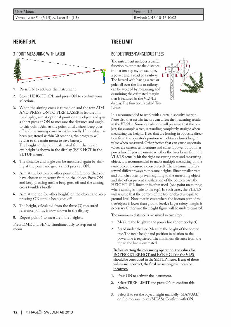
BORDER TREES/DANGEROUS TREESThe instrument includes a useful function to estimate the distance from a tree top to, for example, a power line, a road or a railway. The hazard with having a tree or pole fall over the line or railway can be avoided by measuring and examining the estimated margin that is featured in the VL5/L5 display. The function is called Tree Limit.
It is recommended to work with a certain security margin. Note also that certain factors can affect the measuring results in the VL5/L5. Some calculations will presume that the ob-ject, for example a tree, is standing completely straight when measuring the height. Trees that are leaning in opposite direc-tion from the operator’s position will obtain a lower height value when measured. Other factors that can cause uncertain values are current temperature and current power output in a power line. If you are unsure whether the laser beam from the VL5/L5 actually hit the right measuring spot and measuring object, it is recommended to make multiple measuring on the same object to ensure a correct result. The instrument offers several different ways to measure heights. Since smaller trees and branches often prevent sighting to the measuring object and also often prevent visualization of the bottom part, the HEIGHT 1PL function is often used (one point measuring where aiming is made to the top). In such cases, the VL5/L5 will assume that the bottom of the tree or object is equal to ground level. Note that in cases where the bottom part of the tree/object is lower than ground level, a larger safety margin is necessary. Otherwise the height figure will be underestimated.
The minimum distance is measured in two steps.
1. Measure the height to the power line (or other object).
2. Stand under the line. Measure the height of the border tree. The tree’s height and position in relation to the power line is registered. The minimum distance from the top to the line is estimated.
Before starting the measuring operation, the values for P.OFFSET, TRP.HGT and EYE HGT (in the VL5) should be controlled in the SETUP menu. If any of these values are incorrect, the final measuring result can be incorrect.
1. Press ON to activate the instrument.
2. Select TREE LIMIT and press ON to confirm this choice.
3. Select if to set the object height manually (MANUAL) or if to measure to set (MEAS). Confirm with ON.
HEIGHT 3PL
3-POINT MEASURING WITH LASER
1. Press ON to activate the instrument.
2. Select HEIGHT 3PL and press ON to confirm your selection.
3. When the aiming cross is turned on and the text AIM AND PRESS ON TO FIRE LASER is featured in the display, aim at optional point on the object and give a short press at ON to measure the distance and angle to this point. Aim at the point until a short beep goes off and the aiming cross twinkles briefly. If no value has been registered within 30 seconds, the program will return to the main menu to save battery. The height to the point calculated from the preset eye height is shown in the display (EYE HGT in the SETUP menu).
4. The distance and angle can be measured again by aim-ing at the point and give a short press at ON.
5. Aim at the bottom or other point of reference that you have chosen to measure from on the object. Press ON and keep pressing until a beep goes off and the aiming cross twinkles briefly.
6. Aim at the top (or other height) on the object and keep pressing ON until a beep goes off.
7. The height, calculated from the three (3) measured reference points, is now shown in the display.
8. Repeat point 6 to measure more heights.
Press DME and SEND simultaneously to step out of menu.

Version: 1.2 User ManualRevised: 2013-10-16 10:02 Vertex Laser 5 - (VL5) & Laser 5 - (L5)
© HAGLÖF SWEDEN AB 2013 | 13
AND PRESS ON TO FIRE LASER is shown in the display, aim at the line and give a short press at ON to measure the distance. Aim at the line until a short beep is heard and the aiming cross twinkles briefly. EYE HGT is automatically added to the measuring result.
4. To re-measure, aim again at the line and give a short press at ON. Repeat if necessary.
5. Accept the measured height result with DME or SEND.
6. Continue to measure the height of the tree.
HEIGHT 1PLThe HEIGHT 1PL method is used in cases where you are positioned some distance away from the line.
1. Stand at ground level by the line. Make sure that there are no objects above the line that you plan to measure with laser, to avoid accidentally hitting the wrong object with the laser beam. If you hit the wrong line or object, the measuring results will be incorrect!
2. Select HEIGHT 1PL and press ON.
3. When the aiming cross is turned off and the text AIM AND PRESS ON TO FIRE LASER is shown in the display, aim at the line and give a short press at ON to measure the distance and the angle. Aim at the point until a short beep is heard and the aiming cross twinkles briefly. EYE HGT is automatically added to the measuring result.
4. To re-measure, aim again at the line and give a short press at ON. Repeat if necessary.
5. Accept the measured height result with DME or SEND.
6. Continue to measure the height of the tree.
HT 2PL REF AND HGT VERTEXHT 2PL REF and HGT VERTEX also enable measuring of heights in cases where you are not positioned at ground level under the line. Either laser or ultra sound can be used to measure the distance to a point under the line. It is rec-ommended to use ultrasound in areas where the vegetation is dense. The distance can also be entered manually.
HGT VERTEX – ULTRASOUND1. Start the T3 transponder.
2. Place the transponder under the line. Make sure that the TRP.HGT (transponder height) in the SETUP menu is accurately set. The TRP.HGT can be set to optional height, for example to 0.0m or 1.3m, when used with the monopod staff and adapter.
OBJECT HGT – MEASURING THE
OBJECT
MANUAL - MANUAL HEIGHT1. In cases where the height to the
line is known, use the MANUAL method in menu OBJECT HGT and press ON.
2. Register the known height in metric/feet by stepping up/down with the DME and SEND buttons. Continue to the next digit with ON. Enter the height as 00.0 if you wish to know where the top will hit the ground in rela-tion to your position when/if the tree is felled.
3. Press ON when the last digit has been entered to con-tinue to height measuring.
MEAS – TO MEASURE HEIGHTSIn cases where the height to the line is not known, is needs to be measured. This is made in MEAS in the OBJECT HGT menu. Select the MEAS func-tion and press ON to confirm. You can now select from dif-ferent methods to calculate the height to the line.
LASER: Measuring of the height with laser, EYE HGT included.
HEIGHT 1PL: The height is calculated with laser mea-suring and angle, EYE HGT included.
HT 2PL REF: The height is calculated with two (2) angle results and the distance is measured with laser, TRP HGT included.
HGT VERTEX: The height is calculated with two (2) angle results and the distance is measured with ultrasound or manually, TRP HGT included.
LASERUse the LASER method in cases when you can stand just under the power line.
1. Stand under the line. Make sure that there are no ob-jects above the line that you plan to measure with laser, to avoid accidentally hitting the wrong object with the laser beam. If you hit the wrong line or object, the measuring results will be incorrect!
2. Select LASER and press ON.
3. When the aiming cross is turned on and the text AIM

DELTA
H1 H H2
User Manual Version: 1.2Vertex Laser 5 - (VL5) & Laser 5 - (L5) Revised: 2013-10-16 10:02
14 | © HAGLÖF SWEDEN AB 2013
5. Accept this height result with DME or SEND.
6. Continue to measure the height of the tree.
TREE HGT – MEASURING THE TREE HEIGHTFive (5) different methods can be used to measure the height of a tree: HEIGHT 1PL, HEIGHT 2PL, HT 2PL REF, HEIGHT 3PL and HGT VERTEX. The different methods and how they are used are described under each respective header in this guide.
1. Select the preferred method to measure the tree height and press ON to confirm your choice.
2. Measure the height.
3. Accept the height with DME or SEND.
4. The instrument calculates the divergence and announc-es if it is OK or not (NOT OK). NOT OK in this case means that the tree can be a hazard if felled.
Press DME and SEND simultaneously to step out of menu.
DELTA HGT
DELTA HEIGHT FUNCTION
The Delta Height function is used to estimate the height difference between a point on an imagined straight line be-tween two (2) fixed positions and a third point, for example a power line, where the line sag is the closest to ground level.
1. Go to the place where the line sag is the closest to ground level.
2. Press ON to activate the instrument.
3. Select DELTA HGT and press ON to confirm this selection.
3. Select HGT VERTEX and press ON.
4. Aim at the T3 transponder and press ON to measure the distance and angle. Aim at the transponder until a short beep is heard and the aiming cross twinkles briefly.
5. Aim at the line and keep the ON button pressed until a beep is heard.
6. The height (TRP.HGT included) is now shown on the display.
7. Accept the height result with DME or SEND.
8. Continue to height measuring of the tree.
HGT VERTEX – MANUAL DISTANCE1. Select HGT VERTEX and press ON.
2. Accept the distance shown in the display (M.DIST) with a short press on SEND. If the distance is incor-rect, change it in the SETUP menu. M.DIST refers to the distance between the eye and the point of reference.
3. Aim at the point of reference at a known height, TRP.HGT under SETUP, set to zero (0) if the point of reference is equal to ground level. Press ON to measure the angle to the point of reference. Keep pressing the ON button until a short beep is heard and the aiming cross twinkles briefly. Release the ON button.
4. Aim at the line and press ON until a beep is heard.
5. The height (TRP.HGT included) is now featured on the display.
6. Accept the height with DME or SEND.
7. Continue to height measuring of the tree.
HT 2PL REF – LASERMake sure that there are no objects above the line that you plan to measure with laser, to avoid accidentally hitting the wrong object with the laser beam. If you hit the wrong line or object, the measuring results will be incorrect!
1. Select HT 2PL REF and press ON.
2. When the aiming cross is turned on and the text AIM AND PRESS ON TO FIRE LASER is shown in the display, aim at the line and give a short press at ON to measure the distance and angle to the line. Aim until the angle has been registered and a beep signal goes off and the aiming cross twinkles briefly.
3. Measure the angle to a point under the line. It is recommended to mark the point before starting the measuring operation. Aim at the point and keep press-ing the ON button until a new beep signal is heard.
4. The height is calculated and shown in the display.
Version: 1.2 User ManualRevised: 2013-10-16 10:02 Vertex Laser 5 - (VL5) & Laser 5 - (L5)
© HAGLÖF SWEDEN AB 2013 | 15
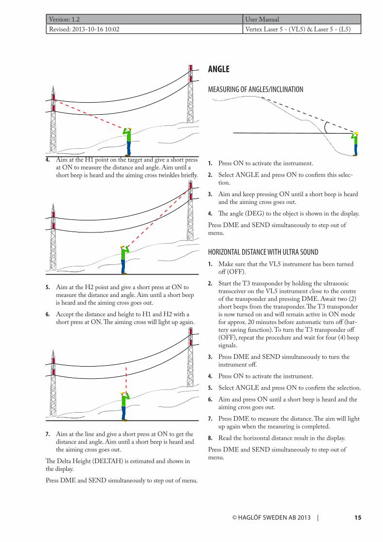
ANGLE
MEASURING OF ANGLES/INCLINATION
1. Press ON to activate the instrument.
2. Select ANGLE and press ON to confirm this selec-tion.
3. Aim and keep pressing ON until a short beep is heard and the aiming cross goes out.
4. The angle (DEG) to the object is shown in the display.
Press DME and SEND simultaneously to step out of menu.
HORIZONTAL DISTANCE WITH ULTRA SOUND1. Make sure that the VL5 instrument has been turned
off (OFF).
2. Start the T3 transponder by holding the ultrasonic transceiver on the VL5 instrument close to the centre of the transponder and pressing DME. Await two (2) short beeps from the transponder. The T3 transponder is now turned on and will remain active in ON mode for approx. 20 minutes before automatic turn off (bat-tery saving function). To turn the T3 transponder off (OFF), repeat the procedure and wait for four (4) beep signals.
3. Press DME and SEND simultaneously to turn the instrument off.
4. Press ON to activate the instrument.
5. Select ANGLE and press ON to confirm the selection.
6. Aim and press ON until a short beep is heard and the aiming cross goes out.
7. Press DME to measure the distance. The aim will light up again when the measuring is completed.
8. Read the horizontal distance result in the display.
Press DME and SEND simultaneously to step out of menu.
4. Aim at the H1 point on the target and give a short press at ON to measure the distance and angle. Aim until a short beep is heard and the aiming cross twinkles briefly.
5. Aim at the H2 point and give a short press at ON to measure the distance and angle. Aim until a short beep is heard and the aiming cross goes out.
6. Accept the distance and height to H1 and H2 with a short press at ON. The aiming cross will light up again.
7. Aim at the line and give a short press at ON to get the distance and angle. Aim until a short beep is heard and the aiming cross goes out.
The Delta Height (DELTAH) is estimated and shown in the display.
Press DME and SEND simultaneously to step out of menu.

User Manual Version: 1.2Vertex Laser 5 - (VL5) & Laser 5 - (L5) Revised: 2013-10-16 10:02
16 | © HAGLÖF SWEDEN AB 2013
IR – COMMUNICATIONData can be sent with IR (infrared light) to the Haglöf Sweden Digitech® Professional or DP II computer calipers or to a special IR receiver that can be mounted in serial port (RS232). Data can be sent from all measuring func-tions. If necessary, use settings Baud 1200bps, 7 data bits, 1 stop bit and even parity.
1. Aim at the VL5 IR ”eye” with the IR receiver ad press SEND.
The distance between the VL5/L5 and the IR receiver should not exceed 10 cm for a successful transfer.
MEM FUNCS - MEMORY FUNCTIONSThe VL5/L5 has built-in memory to save data during height- angle and distance measuring. The data is saved when pressing SEND, provided that the saving function has been activated in the SETUP menu. More than 2000 measuring operations can be saved in the memory. When a measurement is saved, the text DATA SAVED is shown in the display. A measuring can only be saved one time and a new measurement has to be made for the next save.
1. Press ON to activate the instrument.
2. Select MEM FUNCS and press ON to confirm this selection.
3. Use DME and SEND to scroll between the memory functions and press ON to confirm.
PRINT MEM: Prints all saved data via IR or Bluetooth, if activated. The data format on transferred data is set under DATA OUTPUT in the SETUP menu.
DEL LAST: Deletes last saved value.
FORMAT MEM: Deletes all saved values.
MEAN HGT: Calculates and shows mean height and number of height that were included to calculation (H1).
Press DME and SEND simultaneously to step out of menu.
BLUETOOTH – COMMUNICATIONThe instrument has built-in Bluetooth®. The function en-ables wireless transfer to PC, computer caliper or handheld computer. The Setup of the instrument is in ”slave mode”. Some receiving units will ask for a pin code to initiate the connection. The pin code should be activated in the BLUETOOTH menu. The VL5/L5 uses the code 12345 as default.
The distance between two units that are to be connected with Bluetooth should not exceed 10 M or 32 FT. This is the maximum distance for a Bluetooth transfer.
ACTIVATE BLUETOOTH1. Press ON to activate the instrument.
2. Select BLUETOOTH and press ON to confirm.
3. Activate CODE 12345 with ON (if Pin code is requested). If not, select -NONE-with the DME or SEND and press ON.
4. Activate Bluetooth by selecting alternative ON in BLUETOOTH and press the ON button. External units can now connect to the VL5/L5.
Data is sent when you press the SEND button on the VL5/L5 after having measured height, distance or angle. The VL5/L5 will not turn off the Bluetooth function if the instrument itself is turned off. This implies that the VL5/L5 can send data with Bluetooth also if it is turned off and turned on again without having to go through the activat-ing procedure. Note that the instrument will consume more battery with the Bluetooth function activated. It is recommended to turn off the Bluetooth function, for example when you move between different plots in the terrain.
To turn the function off, change the ’ON’ to ’--’ in the BLUETOOTH menu. When the Bluetooth function is activated, the symbol for Bluetooth is shown in the VL5/L5 display as a reminder. The VL5/L5 will turn off the Bluetooth function if it is turned off/inactive for more than 20 minutes. The documentation on available ports for different computer units for Bluetooth connection is often limited and you may need to try different alternatives.

Version: 1.2 User ManualRevised: 2013-10-16 10:02 Vertex Laser 5 - (VL5) & Laser 5 - (L5)
© HAGLÖF SWEDEN AB 2013 | 17
CARE, STORAGE AND MAINTENANCE ♦ Store the instrument in its soft case when carrying. Do not
swing the instrument by its strap.
♦ The instrument is water and dust resistant, but should not be used in water and it is not waterproof.
♦ Use a soft, clean and dry cloth to clean the instrument if exposed to rain, water, sand and mud. Do not use alcohol, benzene, thinner or other organic agents to clean the instrument’s main body! Always clean as soon as possible after the exposure, and always store the instrument in a dry, cool place and away from direct sunlight.
♦ Use a soft oil-free brush to remove dust from the lens surface. To remove stains or smudges (fingerprints etc.), wipe lenses gently with a soft clean cotton cloth or oil-free lens tissue. To clean a lens, moisten it with lens cleaning solution and wipe it clean with a lens cloth or lens tissue. Stubborn smudges can be removed with a small amount of pure alcohol using extra care to avoid scratching of the lens surface. The tissue should only be used one time.
♦ Do not expose the instrument to excessive heat or ultraviolet rays, since this may damage the unit.
♦ When exposed to sudden changes in temperature or high humidity, water condensation may appear on lens surfaces. Do not use the instrument until this conden-sation has evaporated. Dry the instrument at room temperature and store in a cool, dry place.
♦ Keep the instrument and any parts of and for the instrument out of reach of small children. Consult a doctor immediately if a small child has swallowed any parts of the instrument or its packing.
NOTES ON BATTERIES ♦ Rinse skin or eyes well with water if exposed to any
battery fluid. If swallowed, contact a doctor
♦ Do not short-circuit battery chamber terminals, and do not carry any batteries with keys or coins in a pocket.
♦ Keep away from fire and water and do not disassemble batteries.
♦ Avoid strong vibrations, shock, fluid or extremes in temperatures for all batteries. If handled incorrectly, batteries may rupture and leak, corroding equipment and staining clothing
SAFETY AND OPERATION PRECAUTIONSTo avoid injury or material loss, please read these safety and operation precautions thoroughly:
♦ Never look directly at the laser beam or directly at the sun when using the instrument.
♦ Do not use the instrument together with other opti-cal instruments, such as binoculars and lenses. Using an optical instrument together with the instrument increases the danger of eye damage.
♦ Do not depress the ON button while aiming with the eye or looking into the optics from the objective side.
♦ Do not disassemble the instrument. Any signs of disas-sembling will automatically withdraw any warranties and the manufacturer does not guarantee the product.
♦ Never place the instrument in an unstable place.
♦ Never look through the instrument while walking.
♦ If you should develop any symptoms of eye irritation or skin inflammation around the eye due to use of the instrument, consult a doctor immediately.
♦ If the instrument should fail to operate correctly, dis-continue use and consult the manual. If you are unable to fix the problem, contact your local dealer for instruc-tions or where to send the instrument for repair.
♦ The instrument has built-in Bluetooth® for data trans-fer to external devices. There may be local restrictions regarding the use of both Bluetooth® and laser technol-ogy. It is the operator’s responsibility to control that the technology in the instrument is permitted to use in the area where the instrument is operated.
User Manual Version: 1.2Vertex Laser 5 - (VL5) & Laser 5 - (L5) Revised: 2013-10-16 10:02
18 | © HAGLÖF SWEDEN AB 2013
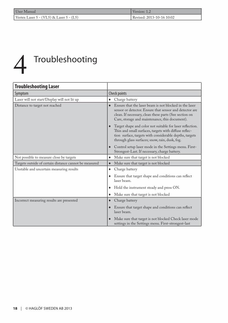
4 Troubleshooting
Troubleshooting LaserSymptom Check pointsLaser will not start/Display will not lit up ♦ Charge batteryDistance to target not reached ♦ Ensure that the laser beam is not blocked in the laser
sensor or detector. Ensure that sensor and detector are clean. If necessary, clean these parts (See section on Care, storage and maintenance, this document).
♦ Target shape and color not suitable for laser reflection. Thin and small surfaces, targets with diffuse reflec-tion surface, targets with considerable depths, targets through glass surfaces; snow, rain, dusk, fog.
♦ Control setup laser mode in the Settings menu. First-Strongest-Last. If necessary, charge battery.
Not possible to measure close by targets ♦ Make sure that target is not blockedTargets outside of certain distance cannot be measured ♦ Make sure that target is not blockedUnstable and uncertain measuring results ♦ Charge battery
♦ Ensure that target shape and conditions can reflect laser beam.
♦ Hold the instrument steady and press ON.
♦ Make sure that target is not blockedIncorrect measuring results are presented ♦ Charge battery
♦ Ensure that target shape and conditions can reflect laser beam.
♦ Make sure that target is not blocked Check laser mode settings in the Settings menu. First-strongest-last

Version: 1.2 User ManualRevised: 2013-10-16 10:02 Vertex Laser 5 - (VL5) & Laser 5 - (L5)
© HAGLÖF SWEDEN AB 2013 | 19
Troubleshooting UltrasoundSymptom Check pointsNo distance presented in display ♦ Ensure that transponder is on/active.
♦ Poor battery.
♦ Repeated noise in surroundings (chain saws, highway traffic, crickets…)
♦ Use of wrong type of transponderMeasured distance values unstable ♦ Repeated noise in surroundings (chain saws, highway
traffic, crickets…)
♦ Poorly calibrated Vertex.Red aim cross will not go out ♦ Ensure transponder to be on/active.
♦ Poor battery.
♦ Repeated noise in surroundings (chain saws, highway traffic, crickets…)
♦ Use of wrong type of transponder.
♦ Angle to object to large – increase distance to object.Vertex unit will not start ♦ Poor battery. Battery input incorrectlyTransponder unit will not start ♦ Poor batteryNo presentation of measuring results ♦ Ensure transponder to be on/active.
♦ Poor battery. Repeated noise in surroundings (chain saws, highway traffic, crickets…) Use of wrong type of transponder.
♦ Angle to object too large – increase distance to object. Measuring instrument is not held steady. Instrument has not registered any horizontal distance.
Unrealistic or incorrect measuring results ♦ Repeated noise in surroundings (chain saws, highway traffic, crickets…)
♦ Measuring instrument is not held steady

User Manual Version: 1.2Vertex Laser 5 - (VL5) & Laser 5 - (L5) Revised: 2013-10-16 10:02
20 | © HAGLÖF SWEDEN AB 2013
WARRANTY AND SERVICE INFORMATIONThe Vertex Laser is covered by a one-year limited warranty. Haglöf Sweden AB warrants that this product shall be free from defects in materials and workmanship, under normal intended use, for a period of 12 months after date of shipment. The warranty excludes the batteries, the accessories and any written materials. The warranty does not apply if the product has been improperly installed, improperly calibrated or operated in a manner not in accordance with the user’s guide. War-ranty is also automatically expired if the product has been opposed to external force and warranty is not applicable for cos-metic defects. The one-year limited warranty time covers obvious fabrication defects. Defects in the electronic components that are impossible for the manufacturer to detect prior to assembling and shipping of the product may occur. Haglöf Sweden AB can in no case be responsible for problems of this nature and has no liability for any loss of business, profits, savings, consequential damages or other damages resulting from use of the products described. Signs of misuse, cosmetic damage, accidents or equal automatically withdraw the warranty. The warranty is valid in the country where your Haglöf product has been purchased. A product covered by warranty will be object to exchange, service, and repair or according to special agreement between seller and buyer, within the frames of the limited warranty. Haglöf Sweden reserves the right to determine which option will be most suitable for each separate case after having examined and evaluated the product.
IMPORTANT ISSUES: ♦ Always contact your Haglöf Sweden representative/distributor/ place where the instrument was purchased for assis-
tance with all questions concerning service and warranty issues.
♦ For a valid warranty, a copy of invoice or dated receipt of your purchase must be presented. The serial number of the returned product has to be clearly stated upon return. Go to www.haglofsweden.com - Support & Service - Service for return form/turn to your supplier for assistance.
♦ The return freight to us is on buyer’s expense. After warranty repair or exchange, the return freight to you is on our expense. If warranty has expired or is null and void, all freights are on buyer’s expense.
♦ If no original invoice can be presented upon shipment, or if two years or more have passed from date of purchase, a customs fee will be added by the applicable customs authorities and possibly in receiving country as well. These fees are on buyers account.
♦ We perform repair and service of products where warranty has expired when possible. Cost estimation will be sent to you after evaluating the returned product for cost approval. Please also see above paragraph on customs fees.
♦ Please do not hesitate to contact us or Haglöf Sweden AB representative for questions or comments!
♦ Any signs of misuse or negligence automatically withdraw our warranty commitments.
SOFTWARE © Copyrights of Haglöf Sweden AB Software belong to Haglöf Sweden AB. Unauthorized duplication is prohibited. Haglöf Sweden AB is registered trademark and VERTEX is a recognized trademark of Haglöf Sweden AB. Production is made in Sweden.
Haglöf Sweden and its suppliers cannot warrant the performance or results when using the firmware, software or hard-ware, nor the documentation. No warranties or conditions are made; neither expressed nor implied, of merchantability, suitability or special fitness for any particular purpose. If software problems appear, please contact your programmer for support. Haglöf Sweden takes no responsibility for loss of income, time, or problems and delays due to problems in soft- or hardware of products. *Copyrights of all software & firmware made by Haglöf Sweden belong to Haglöf Sweden* Any lists and/or information of software for any Haglöf Sweden AB products should be considered as brief descriptions and not as a complete guide to what may and may not be available. For further details, please see ORGALIME SW01, Gene-ral Conditions for Computer Software, and Supplement to ORGALIME S 2000 or ORGALIME SE 94.

Version: 1.2 User ManualRevised: 2013-10-16 10:02 Vertex Laser 5 - (VL5) & Laser 5 - (L5)
© HAGLÖF SWEDEN AB 2013 | 21
5 Technical Specification
DATA FORMATData from the VL5/L5 is sent serial as text. There are three (3) available formats: HAGLOF, NMEA och NMEA EX-TENDED.
HAGLOF Data packet contains a total of 40 signs.
1 0000<LF><CR>
2 0000<LF><CR>
3 0000<LF><CR>
4 0000<LF><CR>
5 +000<LF><CR> (At negative angle ‘+’is replaced with ‘-‘)
<LF>=Linefeed (ASCII 10)
<CR>=Carriage Return (ASCII 13)
At height measuring, the following is sent
Line 1: 1:a height (dm alt. feet X 10)
Line 2: 2:a height (dm alt. feet X 10)
Line3: 3:e height (dm alt. feet X 10)
Line 4: Horizontal distance to the object (dm x 10 alt. ft X10)
Line 5: Angle to object (grads X10)
At distance measuring, the following is sent:
Line 1: 0000
Line 2: 0000
Line 3: 0000
Line 4: Distance to transponder (cm alt feet X 10)
Line 5: Angle to object (grads X10)
*If the angle (line 5) has a larger or smaller value than zero (0) the distance equals the calculated horizontal distance.

User Manual Version: 1.2Vertex Laser 5 - (VL5) & Laser 5 - (L5) Revised: 2013-10-16 10:02
22 | © HAGLÖF SWEDEN AB 2013
NMEAThe NMEA format sends height measuring values only. The text string looks as follows:
$PHGF,HT,htvalue,unit*chksum<LF><CR>
where
$PHGF, is the message identifier
HT, is the type of data, and in this case Height
htvalue, is the calculated height with one (1) decimal
unit, is the measuring unit, M=meter, FT=feet
*chksum is an asterisk followed by a hexadecimal check sum, calculated by XOR all signs between $ and *
<CR> Carriage Return
<LF> Line Feed
Example:
$PHGF,HT,4.1,M*4F<LF><CR>
NMEA EXTENDED The extended NMEA format sends height, horizontal distance and angle to the object
$PHGF,HV,htvalue,htunit,hdvalue,hdunit,angle,angleunit,*chksum<LF><CR>
where
$PHGF, is the message identifier
HV, is the type of data, in this case horizontal vector
htvalue, is the calculated height with one decimal
htunit, is the height unit, M=meter, FT=feet
hdvalue, is the calculated horizontal distance with one decimal
hdunit, is the distance unit, M=meter, FT=feet
angle, is the angle to the object with one decimal
angunit, is the angle unit, D=Grads
*chksum is an asterisk followed by a hexadecimal checksum, calculated by XOR all signs between $ and *
<CR> Carriage Return
<LF> Line Feed
Example:
$PHGF,HV,2.9,M,13.1,M,7.1,D*7F<LF><CR>

Version: 1.2 User ManualRevised: 2013-10-16 10:02 Vertex Laser 5 - (VL5) & Laser 5 - (L5)
© HAGLÖF SWEDEN AB 2013 | 23
PhysicalDimensions(LxWxH) 93x63x72mm/ 3.7x2.5x2.8”Weight: 243 g/9 oz Housing and frame material Glass filled polycarbonateShock/Vibration MIL-STD-810E Moisture: IP67, NEMA 6 Monopod/tripod mount 1/4” female threadOperating temperature: Temperature range -20° to +45°C / -4F to 113F
Power Power consumption Max 0.9WBattery duration Approx. 9000 measurementsBattery type Chargeable Li-Ion 3.7VCharging time Max 3.5hCharger interface USB mini BCharger Wall charger 110/220AC-5VDC, USB mini B interfaceCar charger Car Cigarette Lighter Adapter 12VDC , USB mini B interfaceCable USB mini B Male/USB Type A Male, 0.5m
User interface Buttons 3 multi functional buttonsBuzzer YesDisplay Graphic LCD 100x60pixelBluetooth class 2, Spp (serial profile), pin code 12345Ir Haglöf standard formatData format Nmea or AsciiSight Led crosshairs 1x magnification
MemoryCapacity 2000 set of dataMemory type Non volatileSight Led crosshairs 1x magnification
HeightRange 0-999.9 m/ftResolution 0.1m/ft
Vertical AngleUnits Angle Degrees 360⁰, Grads 400⁰ and %Angle range -55 to +85degResolution angle 0.1degAccuracy 0.1deg

User Manual Version: 1.2Vertex Laser 5 - (VL5) & Laser 5 - (L5) Revised: 2013-10-16 10:02
24 | © HAGLÖF SWEDEN AB 2013
LaserMin range 1.5ft/46cmMax range 2000ft/700m (depending on target)Resolution angle 0.1ft /0.1m Accuracy 0.1ft /4 cmTarget modes First, Last, StrongestWavelength 905nmDivergence 3 mrad (1ft beam diameter @ 328ft (30cm @ 100m)Eye safety Class 1, 7mm (FDA, CFR21) Class 1m (IEC 60825-1:2001)
Ultrasound This applies only to instruments Vertex Laser VL5
Distance (max) to transponder T3
>30m/100ft
Distance (max) to T3 with 360° adapter
>20m/60ft
Resolution 0.01m/0.1ftAccuracy 1% or better when calibrated
Transponder T3Dimensions Diameter 70mm / 2.8”Weight 85g/5oz (battery included)Battery 1x 1,5V AA AlkalinePower consumption 9mW
OtherAdapter/Spreader Plastic, weight app. 30g/1ozMonopod/plot staff 2-parts, height adjustable 33-140cm, weight app. 270g/9.5oz, aluminium/plasticCase Aluminum safety case/Carbon box and soft carrying case

Version: 1.2 User ManualRevised: 2013-10-16 10:02 Vertex Laser 5 - (VL5) & Laser 5 - (L5)
© HAGLÖF SWEDEN AB 2013 | 25
DECLARATION OF CONFORMITYAccording to the EMC Directive with amendment 89/336/EEG & the Low Voltage Directive 73/23/EEG and 93/68/EEG including amendments by the CE Marking Directive 93/68/EEG
Type of equipment Distance and angle meter
Brand name or trade mark Vertex, Vertex Laser, Haglöf Sweden®
Manufacturer’s name, address, telephone & fax no
Haglöf Sweden AB, Klockargatan 8, SE-882 21 Långsele, Sweden
Tel: +46 620-25585, Fax: +46 620-20581, [email protected]; www.haglofsweden.com
The Vertex Laser VL5 and L5 is CE marked 2013
The following standards and/or technical specifications, which comply with good engineering practice in safety matters in force within the EEA, have been applied:
As manufacturer established within EEA, we declare under our sole responsibility that the equipment follows the provi-sions of the Directives stated above.

© HAGLÖF SWEDEN AB 2013
Haglöf Sweden AB ¤ Box 28 ¤ 88221 Långsele ¤ Phone +46 620 255 80, Fax +46 0620 205 81 ¤ www.haglofsweden.com


