
Version 6.8 User Manual © Copyright Inivis Limited 2011 · More than one vertex can occupy the...
57
Version 6.8 User Manual © Copyright Inivis Limited 2011 AC3D Manual file:///C:/Program Files/AC3D 6.8.14/manual/main.ht m 1 of 57 19/06/2011 9:32 AM
Transcript of Version 6.8 User Manual © Copyright Inivis Limited 2011 · More than one vertex can occupy the...

Version 6.8
User Manual
© Copyright Inivis Limited 2011
AC3D Manual file:///C:/Program Files/AC3D 6.8.14/manual/main.htm
1 of 57 19/06/2011 9:32 AM

Welcome to AC3DAC3D is designed to make the construction of 3D objects fast and easy. It is used to create 3D models for simulations, games, rendering ray-traced images andfor scientific and general data visualization.
AC3D runs on a wide range of standard hardware and is available across a number of popular platforms.
AC3D terminology
VertexA vertex is a single point in 3d space. It’s specified by three coordinates x, y and z. More than one vertex can occupy the same position in 3d space. A vertex isalways owned by a single object; they cannot be shared between objects. A vertex is usually part of one or more Surfaces, but need not be.
SurfaceA surface in AC3D is a sequence of vertices. Surfaces are one of three types; polygons, lines or polygon outlines. The type of a surface defines how the surfaceis drawn and this can be easily changed. If a surface is set to be single-sided, it will only be visible from the front. Two-sided surfaces will be visible from bothsides. It is more efficient to draw single sided surfaces and makes more sense when used as part of an object such as a sphere (where you can’t see the otherside of the surfaces). Surfaces have a material attribute, which defines the color and quality (for lighting purposes). Each vertex referenced in a surface has anassociated Texture Coordinate. Vertices can be shared between surfaces in the same object.
Surface normalA ‘surface normal’ specifies the direction a surface is facing. Normals are used in lighting calculations. Surface normals are automatically calculated by AC3D. Asurface is defined as facing the viewer if the vertices can be seen in an anti-clockwise direction.
ObjectAn AC3D object is a list of vertices, and surfaces that use these vertices. It also has other attributes such as a name and texture.
GroupA group is a special object that has no surfaces or vertices but has other objects as children. Groups are created by selecting two or more objects and selecting‘Group’ from the edit menu or toolbar. Use the ‘Ungroup’ function to separate the objects.
Select-modeThe select mode allows control over the level of editing in AC3D. In ‘Vertex’, individual vertices can be selected and adjusted. In ‘Surface’, operations areperformed on one or more selected surface. In ‘Object’, whole objects are selectable. This allows manipulation of objects, even if they are part of groups. In‘Group’, selecting all or part of an object automatically selects the top level object.
MaterialA material defines the color of a surface and also the attributes that define the way it will react to light e.g. shininess.
TextureGraphical images can be mapped onto the surfaces of an object. The images are usually from graphics files such as gif, jpg, bmp etc.
Texture coordinatesWhen the vertex of a surface is drawn, a texture coordinate specifies the position of a texture image to map to that point. A texture coordinate is a twodimensional (u,v) value which defines the point on the 2D image.
AC3D Manual file:///C:/Program Files/AC3D 6.8.14/manual/main.htm
2 of 57 19/06/2011 9:32 AM

Bounding boxWhen you make a selection of objects, surfaces or vertices, a green box outlines it. You can drag, resize or rotate this box to adjust the contents
Getting help User interface components in AC3D have ‘balloon help’. Small
‘tooltip’ windows will popup when the mouse pointer rests over abutton or field label. This feature can be switched off from File->Settings. When browsing through the menu items, the function on each item isdescribed in the message text at the bottom of the AC3D window.
AC3D Manual file:///C:/Program Files/AC3D 6.8.14/manual/main.htm
3 of 57 19/06/2011 9:32 AM

AC3D has a control panel on the left, plus 4 view windows. There’s also the menu and toolbar at the top and an information bar along the bottom.
Control panelThis is where the main controls over the selection and draw modes are located. It also containsthe surface-type controls, the palette of materials and the object name field. The top of the control panel shows information about the current selection. When the mouse isbeing used to interact with models, this area will also display current positions, distances movedand other related information.
ToolbarThis contains buttons for some of the most commonly used functions.
All select everythingNone clear the selectionDup duplicate the selectionCut/Copy/Paste use AC3D’s internal clipboardGroup/Ungroup put selected objects into a group/remove the group objectFlip x/y/z flip the section about this axis200%/50%/+10%/-10% scale the selection uniformly
Maximize a single view or view ALL together
View windowsBy default, AC3D starts with three two-dimensional (2D orthographic) view windows and a single three-dimensional (3D) window. The default view windows showFront, Left, Top and 3D camera angles onto the model space.
The dividers between the 4 view windows can be dragged to resize the views. Individual views are maximized by clicking on the view buttons at the top right ofthe main window (alternatively, the F1-F5 keys can be pressed to switch between the different view configurations). The main window size/position and other settings are saved when AC3D exits.
AC3D Manual file:///C:/Program Files/AC3D 6.8.14/manual/main.htm
4 of 57 19/06/2011 9:32 AM
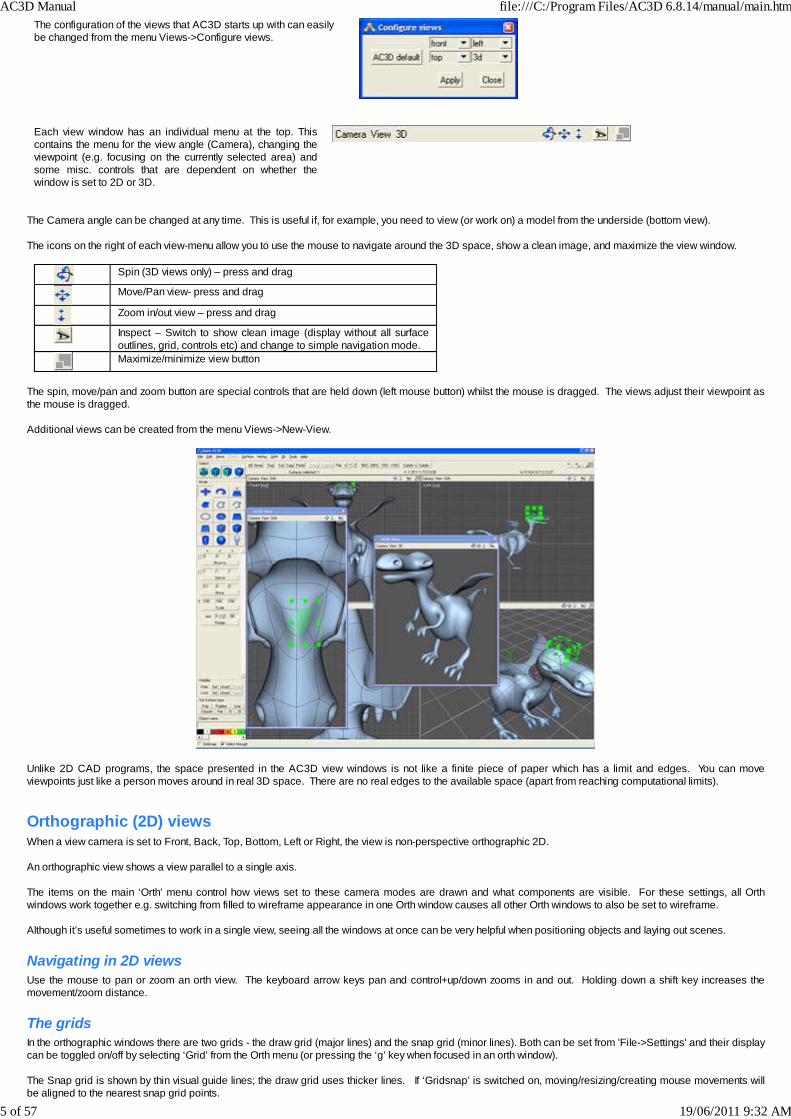
The configuration of the views that AC3D starts up with can easilybe changed from the menu Views->Configure views.
Each view window has an individual menu at the top. Thiscontains the menu for the view angle (Camera), changing theviewpoint (e.g. focusing on the currently selected area) andsome misc. controls that are dependent on whether thewindow is set to 2D or 3D.
The Camera angle can be changed at any time. This is useful if, for example, you need to view (or work on) a model from the underside (bottom view). The icons on the right of each view-menu allow you to use the mouse to navigate around the 3D space, show a clean image, and maximize the view window.
Spin (3D views only) – press and drag
Move/Pan view- press and drag
Zoom in/out view – press and drag
Inspect – Switch to show clean image (display without all surfaceoutlines, grid, controls etc) and change to simple navigation mode.Maximize/minimize view button
The spin, move/pan and zoom button are special controls that are held down (left mouse button) whilst the mouse is dragged. The views adjust their viewpoint asthe mouse is dragged. Additional views can be created from the menu Views->New-View.
Unlike 2D CAD programs, the space presented in the AC3D view windows is not like a finite piece of paper which has a limit and edges. You can moveviewpoints just like a person moves around in real 3D space. There are no real edges to the available space (apart from reaching computational limits).
Orthographic (2D) viewsWhen a view camera is set to Front, Back, Top, Bottom, Left or Right, the view is non-perspective orthographic 2D. An orthographic view shows a view parallel to a single axis. The items on the main ‘Orth’ menu control how views set to these camera modes are drawn and what components are visible. For these settings, all Orthwindows work together e.g. switching from filled to wireframe appearance in one Orth window causes all other Orth windows to also be set to wireframe. Although it’s useful sometimes to work in a single view, seeing all the windows at once can be very helpful when positioning objects and laying out scenes.
Navigating in 2D viewsUse the mouse to pan or zoom an orth view. The keyboard arrow keys pan and control+up/down zooms in and out. Holding down a shift key increases themovement/zoom distance.
The gridsIn the orthographic windows there are two grids - the draw grid (major lines) and the snap grid (minor lines). Both can be set from 'File->Settings' and their displaycan be toggled on/off by selecting ‘Grid’ from the Orth menu (or pressing the ‘g’ key when focused in an orth window). The Snap grid is shown by thin visual guide lines; the draw grid uses thicker lines. If ‘Gridsnap’ is switched on, moving/resizing/creating mouse movements willbe aligned to the nearest snap grid points.
AC3D Manual file:///C:/Program Files/AC3D 6.8.14/manual/main.htm
5 of 57 19/06/2011 9:32 AM

The grids can be configured to display units of any size e.g. for eighths of an inch, the major draw grid would be set to 1.0 and the snap grid set to 0.125 (1/8th).
Using Background ImagesAny orthographic (2D) window can display a background image. This can be useful for tracing shapes or laying out objects in relation to a scanned image e.g. aplan or map. Background images are set and unset from the Orth menu at the top of an orthographic window. All image formats that are supported by AC3D'stexture loaders can be used as background images.
Background images will scale and move with the views. By default the image will be centered on
the origin. The scale and position of the background image is adjusted by using alt and the cursorkeys. Alt and the cursor keys reposition the image, whilst Alt+Shift plus cursor up/down scale theimage. Details of background images are currently not saved with models or when AC3D exits.
3D views
A 3D view window displays the current model in a threedimensional perspective and changes instantly when anymodifications are made to the current model. The main 3D menu (at the top of the main AC3D window)contains controls to switch visibility of many attributes within the3D window. Changing these controls affects all 3D windowswithin the program. A 3d grid is available - toggle with 'g'. The grid lies on the XZplane (floor). 'w' toggles between wireframe and filled drawing, 't' togglestextures. 'l' toggles the fixed light. See the 3D menu for moreviewing options.
Navigating in 3DTwo navigation modes are available in this window – ‘spin’ and ‘walk’. These can be switched from the view’s own 3D menu or by pressing the ‘1’ or ‘2’ keyswhilst the pointer is in the 3D window.
Spin mode Button controls at top of view for spin, pan and zoom From keyboard:Spin- up/down/left/right keys, or Alt+left mouse buttonZoom – Control+up/down
Walk mode Button controls at top of view for walk/fly, pan and tilt From keyboard:Move forward - up-keyMove backward - down-keyTurn - left/right keysMove up/down – alt+up/down Holding down the shift key with the above combinations increases thedistance of travel
Taking a snapshot imageWindows and Mac users can quickly copy the image shown in a view to thesystem clipboard by selecting the item on the Camera menu, which is oneach View window. After selection of this menu item, you may switch to another program e.g. animage editor or word processor program and then ‘Edit->Paste’ within thatin order to insert the image The same function is also available on the Edit menu (for the main 3Dview). Note that the ‘Copy’ item on the Edit menu is used for the internalAC3D clipboard, the item that copies the image to the system must be used
AC3D Manual file:///C:/Program Files/AC3D 6.8.14/manual/main.htm
6 of 57 19/06/2011 9:32 AM

to retrieve the image.
To increase the quality of the image, anti-aliasing can be switched on (fromthe view’s 3D menu). This ‘smooths’ the image. Anti-aliasing slows downrendering of the 3D image so it’s recommended that it only be used whenpreparing images for a snapshot.
Inspect mode
Pressing down the eye icon, which is available on each view, sets the view into Inspect mode. Inspect mode switches off the display of vertices, surface outlinesetc so that a ‘clean’ image is displayed. It also changes the way that you can navigate the view. When inspect mode is on, simply dragging the mouse navigates(normally the alt key would be used). Inspect mode is useful if you are performing a lot of work in the other views and using one view for previewing the changes. It’s also useful with additionalmonitors, where one monitor has a single AC3D view (Views->New-View) that is set to inspect. Work can be performed on the main monitor and inspected(quickly spin or walk) on the other monitor.
AC3D Manual file:///C:/Program Files/AC3D 6.8.14/manual/main.htm
7 of 57 19/06/2011 9:32 AM

AC3D SurfacesObjects in AC3D consist of a collection of vertices and a number ofsurfaces that reference those vertices. A surface may be one of threetypes: Polygon, Polyline or Line. A polygon is a filled area, a Polyline isa wire-frame outline of the polygon (a loop that joins the start vertex tothe end),and a Line has a specific start and end.
Surface type is changed by pressing a button on the control panel. TheSurface type buttons are located at the bottom of the control panel (Poly,Polyline, Line): This panel also contains controls to set surfaces to be smooth or flat Thisdetermines the way that a polygon is drawn (it has no effect on Lines orPolylines).
If a surface is flat-shaded, the color across the surface will be constant. Ifit is shaded then the color will be 'graded' depending on lightingconditions. Vertices can be shared between surfaces (i.e. one or more surfaces usethe same vertex). If these surface types are set to ‘smooth’, the effect isof one continuous 'smooth' surface. The vertices MUST be shared fortwo surfaces to be smoothed together. This method of shading allowssmooth- looking objects to be created from relatively simple shapes.
Crease anglesEach AC3D object has a crease-angle property. This is adjusted via the Tools->Object Property Editor. The crease angle is specified in degrees and is used todetermine if adjacent surfaces in the object should be ‘smoothed together’ by averaging the surface-normals. The angle between adjacent surfaces is measuredand if this is larger than the crease angle the surfaces will be smoothed. A crease angle of zero degrees forces all surfaces to be flat. A crease angle of 180 degrees forces all surfaces to be drawn smooth. Setting a surface type to ‘flat’ forces the surfaces to remain flat shaded. Setting a surface type to smooth allows it to be under control of the crease angle. Example: a cylinder with all surfaces set to ’Smooth’.
crease angle = 0°
All surfaces appear flat.
crease angle = 45°
The cylinder edges are ‘smoothedtogether’ but the end is flat becausethe angle between it and the edgesis > 45°
Crease angle = 91°
The cylinder sides are now shadedalong with the edges.
One-sided and Two-sided surfacesThe '1S' and '2S' buttons select how many sides a surface has (one-sided or two-sided). If a surface is single sided, it will only be visible from one side. Thefollowing pictures demonstrate this:
In this model, there are three objects - a green rectangle, ared rectangle and a blue ellipse (made by creating an ellipseobject and setting the surface type to be ‘Poly’). The red rectangle has been set to be single-sided '1S'. Thismeans that it is visible from the 'front' but not from the back(the second image shows the whole model rotated).
AC3D Manual file:///C:/Program Files/AC3D 6.8.14/manual/main.htm
8 of 57 19/06/2011 9:32 AM
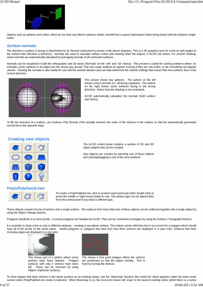
Objects such as spheres and cubes, which do not have any interior surfaces visible, benefit from a speed optimization when being drawn with the surfaces single-sided.
Surface normalsThe direction a surface is facing is determined by its 'Normal' (indicated by arrows in the above diagram). This is a 3D graphics term for a line at right angles tothe surface that indicates a direction). Normals are used to calculate surface colors and shading when the objects in AC3D are drawn. For smooth shading,vertex normals are automatically calculated by averaging normals of all connected surfaces. Normals can be visualized in both the orthographic and 3d views (‘Normals’ on the ‘orth’ and ‘3d‘ menus). This preview is useful for solving problems where, forexample, some surfaces in an object are the wrong way around. This can cause surfaces to appear missing if they are one-sided, or the smoothing can appearuneven. Viewing the normals is also handy for use with the extrude function and can help determine the extrude settings that ensure that new surfaces face in thecorrect direction.
This picture shows two spheres. The sphere on the leftshows correct normals (i.e. all facing outwards). The sphereon the right shows some surfaces facing in the wrongdirection. Notice how the shading is not consistent. AC3D automatically calculates the normals (both surfaceand vertex).
To flip the direction of a surface, use Surface->Flip Normal. (This actually reverses the order of the vertices in the surface so that the automatically generatednormal faces the opposite way).
Creating new objectsThe AC3D control panel contains a number of 2D and 3Dobject shapes that can be created. New objects are created by selecting one of these buttonsand clicking/dragging in one of the view windows.
Polys/Polylines/LinesTo create a Poly/Polyline/Line, click to position each point and either double-click orpress the middle or right mouse button to end. The surface type can be altered laterfrom the control panel if you need a different type.
These objects consist of a list of vertices and a single surface. The surfaces from more than one of these objects can be collected together into a single object byusing the Object->Merge function. Polygons should be 3 or more points. Concave polygons are handled by AC3D. They can be converted to triangles by using the Surface->Triangulate function. It is possible to draw a line or poly in different windows - creating a non-planar surface. This makes sense with lines but is not correct for a polygon which shouldhave all of the points on the same plane. Invalid polygons i.e. polygons that have less than three vertices are displayed in a cyan color. Surfaces that havecrossing edges are displayed in a red color.
This shows part of a sphere where somevertices have been deleted. Polygonsurfaces with only 2 vertices have beenleft. These can be removed by usingObject->Optimize Surfaces.
This shows a four point polygon where the verticesare positioned so that the edges overlap. This isfixed by moving the vertices.
To draw shapes that have vertices in the same position as an existing shape, use the ‘Nearsnap’ function; the control for which appears under the draw modesection when /Poly/Polyline/Line mode is selected. When Nearsnap is on, the next point drawn will ‘snap’ to the nearest existing vertex (when there is a vertex
AC3D Manual file:///C:/Program Files/AC3D 6.8.14/manual/main.htm
9 of 57 19/06/2011 9:32 AM

within a certain range).
Spheres, boxes etc.Creating a 3D object by dragging the mouse in a window specifies two of thedimensions for the new object - the third dimension is an average of the originaltwo. The location of the object in the third dimension is specified by the 3Dcursor. These objects can also be created with a single click in a view window. Thiswill create a regular object that fits into a 1 x 1 x 1 square.
The 3D cursor is shown in the orthographic views by a cross. This is repositioned by using the tool, Tools->Position-3D-Cursor. Most people rarely use thisbecause it is very easy to create an object and position it afterwards.
Some object types allow parameters to be set beforecreating the object. For example, spheres and meshes canbe made from triangles or quads. Controls for any available parameters appear in the panelunderneath the Mode box on the control panel.
Naming objectsWhen created, AC3D Objects are automatically named. The object name box is at the bottom of the control panel and allows these names to be set. Object names can only be edited/set in Group or Object select mode. Object names need not be unique and can be the same across multiple objects. This canbe useful for selecting or finding particular objects with the Edit->Select-by-name function (e.g. to select all objects named ‘chair’). Object names are used insome of the file formats exported by AC3D. If AC3D is being used to generate VRML or Dive files, URLs and other text can be associated with objects. This text is used in a number of the export file formatsthat AC3D generates. The names, text and URLs are saved in the .ac AC3D files. Text attached to each object is entered into the field on the Tools->ObjectProperty Editor window. Object names can also be set in the property editor.
LightsLights have no associated geometry and represent a ‘point light’. In the AC3D views, lights are represented by this symbol:
Lights are fixed brightness white lights. Lights are selected and repositioned in Group or Object select mode.Lights are generated in exported files such as POV and RIB files. The generated files can be edited to alter the lighting attributes.
This image shows a green sphere with two lights (indicated by white spheres) - themain headlight is off. (The headlight in the 3D window is toggled on and off with the 'l'key, or from the main ‘3D’ menu).
If the headlight is on when POV or RIB files are generated, a light will be added to information in the file.
Object mode lock
AC3D Manual file:///C:/Program Files/AC3D 6.8.14/manual/main.htm
10 of 57 19/06/2011 9:32 AM
Clicking twice on an object mode button causes the mode to ‘lock’. This is indicated by the button changing to green. When a mode islocked, the mode does not revert to Move/size after an object iscreated. Pressing Move/Size, Rotate (or extrude) releases the lock.
Creating other objectsIt is very easy to create other objects from these shapes. For example, to make a torus shape (‘donut’), create an ellipse and select Object->Revolve. A cone can be made in a number of ways. Create a cylinder; select one end (in vertex mode) and select Vertex->Snap Together. A cone made this way will havethe texture coordinates set correctly. For a simpler cone (fewer vertices), optimize the vertices with Object->Optimize Vertices. This means that the centre-point ofthe cone will be a single vertex which is shared with all the sides. Some other ways of making cones include making a 'disk' and pulling the centre point up orusing Object->Revolve to revolve a line around an axis. ‘Extrude’ is used to add extra parts to objects or to give 2d shapes depth. Objects can be cut into pieces and specific surfaces deleted.
AC3D Manual file:///C:/Program Files/AC3D 6.8.14/manual/main.htm
11 of 57 19/06/2011 9:32 AM
In AC3D, the manipulation of 3D objects works in a very similar way to a 2D drawing program i.e. the selection is shown highlighted and ‘handles’ can be movedto reshape the section.
Selected components (surface, vertices) are shown in a different color and aresurrounded by a ‘bounding box’ (usually green). Selection is possible in move/size, rotate and extrude modes. The default mode ismove/size.
Selecting
The Select-mode defines the granularity of selection i.e. it determines if selections will affect objects, groups or vertices. To select in AC3D, either click the leftmouse button or use the left mouse button to drag a box over an area. When something is selected, the bounding-box that appears can be dragged or resized,directly affecting the points/surfaces/objects.
Vertex mode vertices can be selected by a single click on a single vertex or by dragging a box over anumber of vertices
Surface-mode a single surface is selected by a click . Multiple surfaces are selected by dragging a boxover an area
Object-mode selecting any part of an object causes the whole object to be selected
Group-mode a group of objects can be selected by highlighting any part of a single object that belongsto a group
There is an important difference between a click-select and a drag -select. Click-selects are used for selecting single entities e.g. one object, one surface, onevertex. A click- select will select the nearest entity underneath the pointer. A drag-select will select everything within the drawn box that lies underneath the region.Click-select is useful, for example, when selecting a single surface of a sphere (where a drag -select will always select more than one surface). Selections are preserved between changes of select modes. Changing from vertex to surface select-mode means that any surfaces that have all verticesselected will remain selected in surface-mode.
ResizingDragging the ‘handles’ at the corners of the bounding box, using the leftmouse-button, resizes the selection. Holding down the control key whilst dragging an edge handleresizes opposite edges. On the corner handles, holding down thecontrol key scales the selection uniformly.
Resize selections of vertices and surfaces
It is possible to resize a selection down to zero width/height. This is useful for lining up vertices.
AC3D Manual file:///C:/Program Files/AC3D 6.8.14/manual/main.htm
12 of 57 19/06/2011 9:32 AM

MovingThe green bounding box is dragged with the left mouse button toreposition the selection. Holding the control key down whilst dragging, constrainsmovement to up/down or left/right only. In a 3D view, AC3D displays green arrows on each side of the boundingbox. These can be dragged to move the selection.
RotatingWhen the rotate button is selected, clicking on the bounding box anddragging left/right will rotate the selection about the point of the firstclick.
Extending/Negating the selectionHolding down the shift key whilst selecting with the left mouse button extends the selection (adds new entities). Pressing shift whilst selecting with the 2nd (or 3rd)mouse button negates (subtracts) items from the current selection. Extend and negate selection work in all select modes.
This picture shows the top and bottom of a sphere selected. This is done by first selecting the top vertices with a drag,then holding down the shift key and dragging across the bottom of the sphere.
Clearing the selectionClicking outside the area of the bounding box will cause everything to become unselected.The selection can also be cleared by pressing the ‘None’ button in the toolbar or from the menu Edit->Select Nothing.
Hiding objectsHiding allows objects to be temporarily removed from theviews. The current selection, or objects that are notselected, can be hidden from view. The 'Unhide' buttonensures that all objects are visible. The ‘Show Hidden’toggle in the main 3D menu determines if the hidden objectsare visible in 3d views. Hiding is useful when access isneeded to work on obscured objects.
Locking objectsLocking is useful for temporarily disabling objects that areobscuring others. When objects are locked, it’s not possibleto select them.
AC3D Manual file:///C:/Program Files/AC3D 6.8.14/manual/main.htm
13 of 57 19/06/2011 9:32 AM

Locking also helps with the speed performance whenediting large models. It works in a similar way to hiding,except that locked objects are drawn in grey wireframe.
Note that if objects are hidden (or locked) and the model is saved/exported, hidden and locked objects are included in the file.
AC3D Manual file:///C:/Program Files/AC3D 6.8.14/manual/main.htm
14 of 57 19/06/2011 9:32 AM

Operations on objectsThese operations are on the ‘Object’ menu and act upon one or more selected objects.
Texture Each object can have one texture. A texture is a 2D bitmap image, such as a .gif or .jpg file, which is drawn onto the surfaces of an object. To set a texture on an object, use Object->texture->Load texture. AC3D’s default palette of objects predefine the way that the textures are mapped onto the objectsurface. To adjust this, or to define a custom mapping, use AC3D’s Texture Coordinate Editor (Tools menu). See the section on ‘Texturing’.
RevolveRevolving makes copies of the selected objects, rotating each copy, and then creating surfaces between the copies. It’s recommended that this function be usedto revolve 2D outlines of shapes rather than filled-polygon objects. Any revolved line objects are automatically removed after the revolution. The axis around whichthe revolution is performed can be altered.
To create a torus - make a circle in the Front window: Select 'Object->Revolve…'
Set the axis to Y and click Revolve. You should see somethinglike this:
Select the 'smooth' surface type (near the bottom ofthe control panel) to make it appear rounded
The degrees of revolution can also bealtered- e.g. 270 degrees:
AC3D Manual file:///C:/Program Files/AC3D 6.8.14/manual/main.htm
15 of 57 19/06/2011 9:32 AM

If there are points that need to be in the centre of the final revolved object - (e.g. the start and end points of the cup profile above) then these points should lieexactly on the axis. Drawing the line with ‘Gridsnap’ can ensure this. Alternatively, snapping the points to the grid (Vertex->Snap to Grid) or by using the controlpanel Move-to function to ensure that two of the values are zero. If these points are not exactly on the axis a small hole or possibly overlapping surfaces will becreated. If this happens, the 'Vertex->Snap Together' function and Object->Optimize Vertices can be used to remove duplicate points.Setting the revolve offset allows the profile to be moved along an axis for each revolution. This is useful for making spiral pipes, springs and screw threads. Example: creating a spring:
Example: creating a thread
MirrorThe mirror function duplicates all object surfaces and vertices and flips the new surfaces and vertices around the specified axis.Examples:
A hemisphere
Object->Mirror-> +X
Object->Mirror-> -X
Object->Mirror-> X axis
Where possible, Mirror will remove duplicate vertices. If mirroring half of a shape, use Vertex->Align to Axis to align the inner edge vertices to an axis.Alternatively, select the inner vertices and resize one dimension to zero – this flattens the selection, aligning the vertices.
AC3D Manual file:///C:/Program Files/AC3D 6.8.14/manual/main.htm
16 of 57 19/06/2011 9:32 AM

Mirror is useful after use of the AC3D real-time Mirror function (View menu) where half of a symmetrical object has been worked on.
BooleanBoolean operations allow objects to be cut and intersected with one another. See the chapter dedicated to Booleans.
Optimize VerticesThis function removes duplicate vertices from each selected object. For vertices to be removed an object must own the vertices and they much match the sameposition exactly. The function will share one vertex between each connected point. This can make the object less complex and means that vertex normals can becalculated if smooth shading is required. This function also removes duplicate vertex references from the surface - something that might cause a bad polygon. Ifvertices do not match the same position, Vertex->Snap Together or Vertex->Snap Together by Distance can be used to move them to the same point.
Optimize SurfacesThis function removes any duplicate surfaces and any polygons that consist of 1 or 2 vertices (these may exist if vertices have been deleted from an object).AC3D highlights invalid polygons by displaying them as cyan lines.
ReduceThis function reduces the number of vertices (and polygons) whilst trying to retain as much of an object’s original shape as possible. This is useful for saving onstorage space and for speeding up the rendering of complicated objects. This function can be used to create different objects that will be shown at differentdistances (LOD – level of detail). For example, a car object should be viewed close up with all polygons, but from a distance a more simple shape is adequateand can save drawing time.
A target percentage specifies the proportion of vertices that are to remain. For example, if an object has 100 vertices and “80%” is entered, the final object willcontain 80 vertices. The original object can remain in the model, or it can be replaced with the new object. If the original object is kept, the new object will be created in the sameposition and will be selected. An example:
732 surfaces, 376 vertices Reduced to 40% gives:
276 surfaces, 150 vertices: a saving of 456 polygons.The reduce window remains visible so that different reductions can be tried (use Edit->Undo to revert to the previous state).
Subdivide + / Subdivide -These functions change the subdivision level. A surface subdivision is where each surface is divided, and then the shape of the overall object is ‘smoothed’.
AC3D Manual file:///C:/Program Files/AC3D 6.8.14/manual/main.htm
17 of 57 19/06/2011 9:32 AM

Original object
Single subdivision
Two subdivisions
Three subdivisions
without surfaces displayed:
Commit subdivisionThis function affects objects that have the subdivision preview level set to a value larger than zero. The subdivision preview level is set from Tools->ObjectProperty Editor or by adjusting the subdivision level from Object->Subdivide +/- (also from the toolbar controls). It converts the subdivision preview into real polygons for the selected objects. See the section on ‘Subdivision surfaces’ for more information.
Re-centreObject centres define the ‘local origin’ of AC3D objects. Object centres can be seen by switching on the '+' button on the main Orth menu. This function sets thisorigin at the centre of gravity. This can be useful for specifying where the pivot points or local-origin of an object are.
Minimum-centreThis function sets the object-centre (object's origin) to the minimum xyz of the object.
FragmentFragment creates one object per surface of the original object so that each object contains only one surface and the necessary vertices. The surfaces are nolonger 'smoothed' together - this is because each surface is now a separate object and vertices cannot be shared across objects. If you need to extract a numberof surfaces from an object, using Surface->Cut Away Object is recommended.
AC3D Manual file:///C:/Program Files/AC3D 6.8.14/manual/main.htm
18 of 57 19/06/2011 9:32 AM

MergeThis function places all of the surfaces from the selected objects into one single object. This does not optimize the vertices so that they can be shared across thesurfaces. Use menu Object->Optimize Vertices after merging to create a more efficient object and/or get smooth shading across adjacent surfaces.
ExplodeThis is similar to fragment, but each new object is moved forward in the direction the surface is facing by a specified amount.
Extrude Along PathThis function ‘sweeps’ a profile along a specified path to create a 3D shape. The operation works on two objects: the profile and the path. The order in whichthese objects are selected is important. The profile should be selected first and the path second (usually with shift-select). An example:
Ensuring that the select mode is Object, first select the circle, then hold down the shift key and select the line. Next select Object->Extrude Along Path:
The shapes created by this function can easily be smoothed by using AC3D’s subdivision. In the following image, the line has been subdivided twice, smoothingthe appearance. It is possible to reposition the vertices in this line to fine-tune the desired shape. After using Extrude Along Path, the new object initially appearsthe same as before but once subdivided, has the same smooth profile as the original line/path.
Operations on surfaces
Extruding
Pressing the extrude button on the control panel (or pressing the ‘e’ key) when there are one or more surfaces selected enables the function. The actual extrude isdone after the selection is dragged.
AC3D Manual file:///C:/Program Files/AC3D 6.8.14/manual/main.htm
19 of 57 19/06/2011 9:32 AM
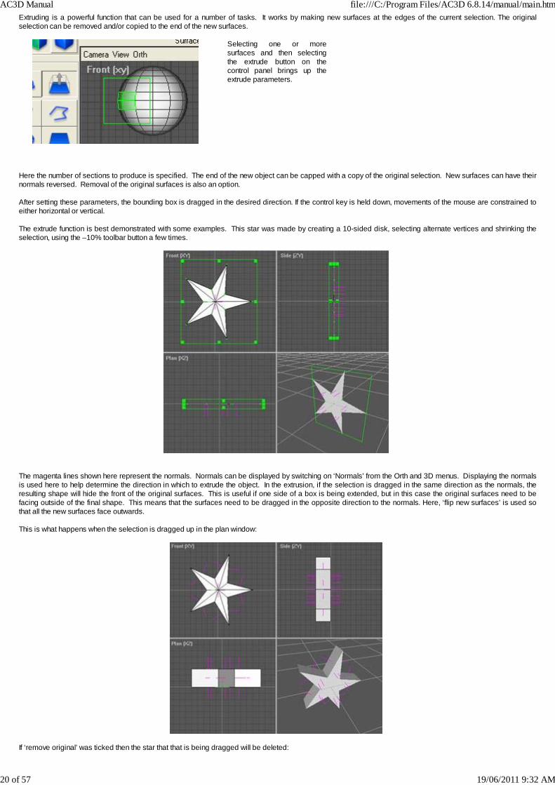
Extruding is a powerful function that can be used for a number of tasks. It works by making new surfaces at the edges of the current selection. The originalselection can be removed and/or copied to the end of the new surfaces.
Selecting one or moresurfaces and then selectingthe extrude button on thecontrol panel brings up theextrude parameters.
Here the number of sections to produce is specified. The end of the new object can be capped with a copy of the original selection. New surfaces can have theirnormals reversed. Removal of the original surfaces is also an option. After setting these parameters, the bounding box is dragged in the desired direction. If the control key is held down, movements of the mouse are constrained toeither horizontal or vertical. The extrude function is best demonstrated with some examples. This star was made by creating a 10-sided disk, selecting alternate vertices and shrinking theselection, using the –10% toolbar button a few times.
The magenta lines shown here represent the normals. Normals can be displayed by switching on ‘Normals’ from the Orth and 3D menus. Displaying the normalsis used here to help determine the direction in which to extrude the object. In the extrusion, if the selection is dragged in the same direction as the normals, theresulting shape will hide the front of the original surfaces. This is useful if one side of a box is being extended, but in this case the original surfaces need to befacing outside of the final shape. This means that the surfaces need to be dragged in the opposite direction to the normals. Here, ‘flip new surfaces’ is used sothat all the new surfaces face outwards. This is what happens when the selection is dragged up in the plan window:
If ‘remove original’ was ticked then the star that that is being dragged will be deleted:
AC3D Manual file:///C:/Program Files/AC3D 6.8.14/manual/main.htm
20 of 57 19/06/2011 9:32 AM
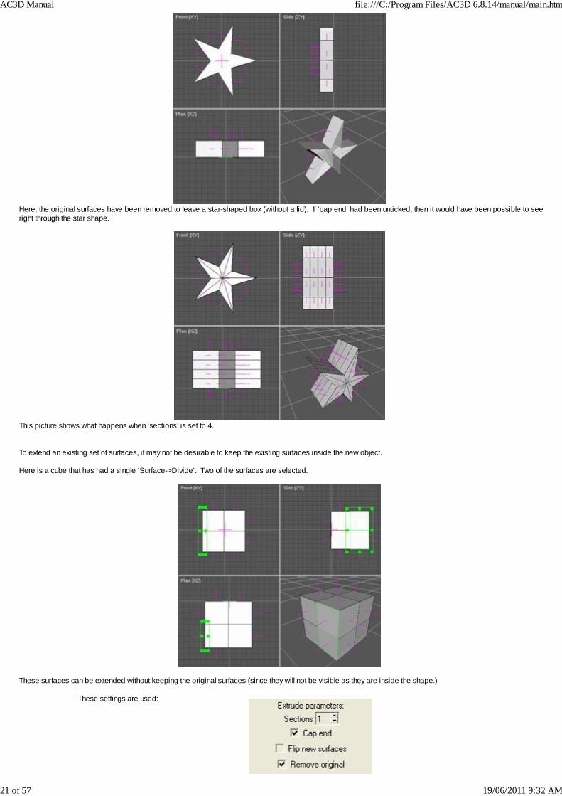
Here, the original surfaces have been removed to leave a star-shaped box (without a lid). If ‘cap end’ had been unticked, then it would have been possible to seeright through the star shape.
This picture shows what happens when ‘sections’ is set to 4. To extend an existing set of surfaces, it may not be desirable to keep the existing surfaces inside the new object. Here is a cube that has had a single ‘Surface->Divide’. Two of the surfaces are selected.
These surfaces can be extended without keeping the original surfaces (since they will not be visible as they are inside the shape.)
These settings are used:
AC3D Manual file:///C:/Program Files/AC3D 6.8.14/manual/main.htm
21 of 57 19/06/2011 9:32 AM

To perform the extrusion, the bounding box is dragged to the left (in either the front or plan window). Holding down the Control-key whilst dragging ensures that thenew surfaces are square to the original. This gives:
When extruding lines, ensure that Remove original is ticked and Cap end is un-ticked. This ensures that no lines remain in the new surfaces.
It is useful to switch on the display of normals when extruding to check that the resultant surfaces are facing in the correct direction. If they are not, select thesurfaces and use Surface->Flip Normal.
Flip normalThis effectively reverses the list of the vertices in each selected surface. This reverses the way that a poly 'faces'. A polygon is defined as 'facing' if the verticesappear anti-clockwise to the viewer. If a polygon is set to be one-sided (by pressing the '1S' button on the control panel) then it will only be viewable from onedirection - the direction it is facing. The display of normals can be switched on in the orth and 3D windows – this can help determine if any surfaces are facing inundesired directions.
Change vertex orderThis changes the order in which the vertices of a surface are drawn, by moving the first vertex to the end of the vertex list. This can be used to change the positionof a break in a line. It can also be used to fix a bad polygon, which has the first three vertices in a non anti-clockwise order - causing the normal (used for lighting)to be incorrectly calculated. If a polygon appears all black, this function may need executing (possibly repeatedly) until it appears correctly.
Flip Triangle EdgeGiven two adjacent triangles, the joining edge is flipped:
Divide
AC3D Manual file:///C:/Program Files/AC3D 6.8.14/manual/main.htm
22 of 57 19/06/2011 9:32 AM

Divide creates new surfaces by splitting eachsurface to make quads (four point/four sidedsurfaces)
Note that because this function splits surface edges, it affects any surfaces that are adjacent to those being divided.
This image shows a box that has had the topsurface divided. The red surfaces that areadjacent now have five points each because thedivision inserted an extra vertex.
CombineCombine takes two or more adjacent surfaces and creates a single surface.The selected surface must share edges for this function to complete. Select the menu item or press the ‘c’ key to execute the function.
two surfaces selected after combine – one surface
It is possible to combine surfaces that do not lie on the same plane. It is recommended that the vertices be flattened in order to make them lie on the same plane. If after combining surfaces, the new surface appears black from every angle, this means that the first three vertices of the surface form an angle of more than 180degrees. To prevent this, the vertex order must be changed (Surface->Change Vertex Order) so that the first three vertices of the surface form an angle less than180 degrees.
FlattenThis acts on multiple surfaces and aligns the vertices so that they all lie on the same plane.
Before After Surface->Flatten
Spike
AC3D Manual file:///C:/Program Files/AC3D 6.8.14/manual/main.htm
23 of 57 19/06/2011 9:32 AM
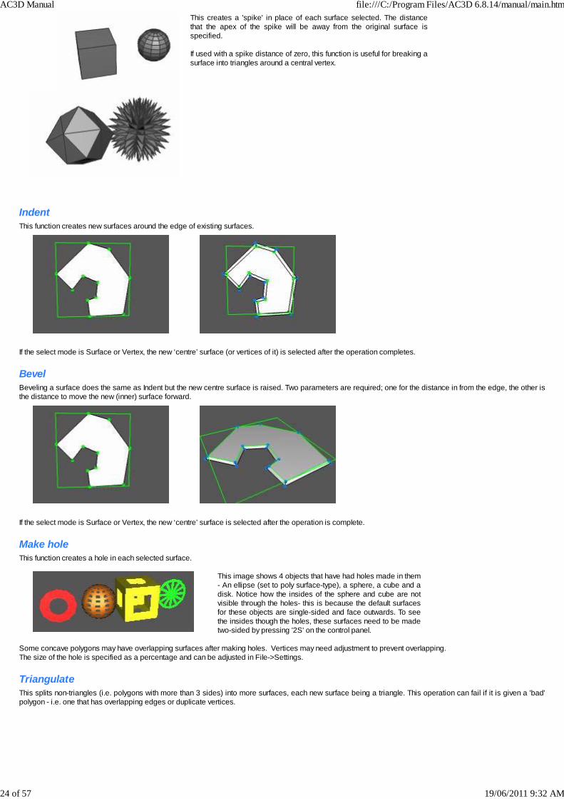
This creates a 'spike' in place of each surface selected. The distancethat the apex of the spike will be away from the original surface isspecified. If used with a spike distance of zero, this function is useful for breaking asurface into triangles around a central vertex.
IndentThis function creates new surfaces around the edge of existing surfaces.
If the select mode is Surface or Vertex, the new ‘centre’ surface (or vertices of it) is selected after the operation completes.
BevelBeveling a surface does the same as Indent but the new centre surface is raised. Two parameters are required; one for the distance in from the edge, the other isthe distance to move the new (inner) surface forward.
If the select mode is Surface or Vertex, the new ‘centre’ surface is selected after the operation is complete.
Make holeThis function creates a hole in each selected surface.
This image shows 4 objects that have had holes made in them- An ellipse (set to poly surface-type), a sphere, a cube and adisk. Notice how the insides of the sphere and cube are notvisible through the holes- this is because the default surfacesfor these objects are single-sided and face outwards. To seethe insides though the holes, these surfaces need to be madetwo-sided by pressing '2S' on the control panel.
Some concave polygons may have overlapping surfaces after making holes. Vertices may need adjustment to prevent overlapping.The size of the hole is specified as a percentage and can be adjusted in File->Settings.
TriangulateThis splits non-triangles (i.e. polygons with more than 3 sides) into more surfaces, each new surface being a triangle. This operation can fail if it is given a 'bad'polygon - i.e. one that has overlapping edges or duplicate vertices.
AC3D Manual file:///C:/Program Files/AC3D 6.8.14/manual/main.htm
24 of 57 19/06/2011 9:32 AM
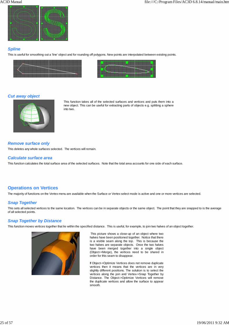
SplineThis is useful for smoothing out a 'line' object and for rounding off polygons. New points are interpolated between existing points.
Cut away objectThis function takes all of the selected surfaces and vertices and puts them into anew object. This can be useful for extracting parts of objects e.g. splitting a sphereinto two.
Remove surface onlyThis deletes any whole surfaces selected. The vertices will remain.
Calculate surface area This function calculates the total surface area of the selected surfaces. Note that the total area accounts for one side of each surface.
Operations on VerticesThe majority of functions on the Vertex menu are available when the Surface or Vertex select mode is active and one or more vertices are selected.
Snap TogetherThis sets all selected vertices to the same location. The vertices can be in separate objects or the same object. The point that they are snapped to is the averageof all selected points.
Snap Together by DistanceThis function moves vertices together that lie within the specified distance. This is useful, for example, to join two halves of an object together.
This picture shows a close-up of an object where twohalves have been positioned together. Notice that thereis a visible seam along the top. This is because thetwo halves are separate objects. Once the two halveshave been merged together into a single object(Object->Merge), the vertices need to be shared inorder for this seam to disappear. If Object->Optimize Vertices does not remove duplicatevertices then it means that the vertices are in veryslightly different positions. The solution is to select thevertices along the join and Vertex->Snap Together byDistance. The Object->Optimize Vertices will removethe duplicate vertices and allow the surface to appearsmooth.
AC3D Manual file:///C:/Program Files/AC3D 6.8.14/manual/main.htm
25 of 57 19/06/2011 9:32 AM

Snap to GridThis moves each selected vertex to the nearest grid position. This may or may not be the visible grid. The snap grid is defined by 'snap grid' in settings and maybe different to the 'draw grid' (which is the visible grid).
Snap Objects by Vertices One vertex in each of two separate objects should be selected before executing this function. The objects will be moved together so that the two selected verticesare in the same location.
Smooth ShapeThis function repositions the selected vertices in order to smooth the shape of the surfaces.
Align to AxisThis function moves all selected vertices so that they lie on the specified axis.
WeldWeld removes duplicate vertices where more than one vertices lie in the same position.
UnweldThis creates new vertices so that each surface will access a unique vertex in the same object. New vertices will be created in the same location as the originals.
Insert VertexThis function inserts a new vertex between each selected pair of vertices. Insert Vertex is useful for adding extra points into a line. If the two vertices selected are on an edge which is shared by two or more surfaces, only one vertex will be created, but it will be shared across the surfaces.
Divide Triangle EdgeThis function takes two selected vertices and divides the edge between two triangles. This splits each triangle into two further triangles.
two vertices selected after the edge division
Extrude EdgesThis function provides a quick way of performing a simple extrude on one or more surface edges (i.e. between vertices).
AC3D Manual file:///C:/Program Files/AC3D 6.8.14/manual/main.htm
26 of 57 19/06/2011 9:32 AM

Vertices selected. After Vertex->Extrude Edges, thenew surfaces and vertices havebeen created but are not fully visibleuntil moved.
The selection is moved upwards,showing the new surfaces.
Slice SurfaceThis function is used to cut one or more surfaces across selected vertices.
Single surface with two verticesselected
After Vertex->SliceSurface – now twosurfaces
A row of vertices around acylinder is selected
After Vertex->SliceSurface – each surface iscut into two
Create Convex Surface/ObjectThis function uses a technique called 'convex hull' to create a new object that surrounds the vertices that are selected. This is very useful for joining complexobjects together or for simplifying the creation of some complex shapes.
These two pictures show the function being used to join acylinder to a cube.
AC3D Manual file:///C:/Program Files/AC3D 6.8.14/manual/main.htm
27 of 57 19/06/2011 9:32 AM

Note that because this function makes a new object, thevertices are not shared with the old objects. If the whole shape i.e the original objects plus the new part- isrequired to be smooth then the objects must be mergedtogether (Object->Merge) and then have the duplicate verticesremoved (Object->Optimize Vertices)
A second example uses a number of simple objects, which are 'shrink-wrapped' by this function. In this case we are creating the fuselage of an aircraft. Theobjects are ellipses and a single red box. Any AC3D objects can be used this way, either lines or polygons.
To get a more accurate outline,these shapes could have beenmade by placing backgroundimages of a real aircraft onto theviews and building the shapes ontop of those images.
After Surface->Create Convex Surface/Object menu function has been selected:
This picture shows the fuselageobject created from the simpleshapes. It has been dragged tothe side of the original objects,which still remain in the scene.It’s important to note that the hullcreated is ‘convex’. This meansthat if there had been anyvertices that were totally ‘inside’the encompassing hull, the newhull object would not have anyvertices created at those points. This function will also create 2dimensional convex hulls,provided all of the selectedvertices lie on the same plane. Ifthey are not, a 3d object will becreated.
Create Ordered SurfaceThis function creates a surface using the individual vertices that are selected. The vertices should be selected in the correct order and in an anti-clockwisedirection. This function works by creating a new surface and adding vertices in the order they were selected. If vertices are not selected in exactly the correctorder, a bad surface (crossing edges or non-planar) may be created.
Create Quad
AC3D Manual file:///C:/Program Files/AC3D 6.8.14/manual/main.htm
28 of 57 19/06/2011 9:32 AM

This function is used to create a four point, four sided surface from three selected vertices.
Before Vertex->Create Quad After new surface created andnew vertex selected
New vertex is positioned asdesired
Create 2D MeshThis function uses a technique called ‘Delaunay Triangulation’ to calculate triangles between a set of points. When this function is selected a plane is specified. This treats the points as 2D so that a mesh can be laid out over the points.
Example: here are a number of vertices inthe front window.
After Vertex->Create 2D Mesh->Front isapplied.
To make vertices specifically for this function: create a line, placing each point at the desired location and select the line and Surface->Remove Surface Only. Thisremoves the surface and leaves the vertices. Note that this function works convexly.
AC3D Manual file:///C:/Program Files/AC3D 6.8.14/manual/main.htm
29 of 57 19/06/2011 9:32 AM

Boolean operations AC3D’s powerful Boolean functions take two objects and perform a volume-based operation between them. The functions reside in the Object->Boolean main menu. Each function requires two objects to be selected. To select two objects: first switch to Object (or Group) selection mode; one object is selected in the normal manner, then the second object can be selected byholding the shift key and clicking (or dragging over) another object. In the following image a sphere has been positioned to overlap with a box. The subsequent sections illustrate the operations that can be performed from theintersection of these shapes.
SubtractUsing Object->Boolean->Subtract, the second object is ‘subtracted’ from the first as if they were solid shapes. This image illustrates the result of the subtraction.
IntersectAfter Object->Boolean->Intersect, a new object is created from the overlapping solid volume between the two objects.
UnionSelecting Object->Boolean->Union creates a single object from the two objects. The overlapping portion is removed. Order of selection is unimportant. As the function’s result does not appear to be very different to the original objects, the result is best illustrated here in wireframe.
AC3D Manual file:///C:/Program Files/AC3D 6.8.14/manual/main.htm
30 of 57 19/06/2011 9:32 AM

Before Union operation. After Union – any internal surfaces have been removed.
Cut awayThe Object->Boolean->Cut-Away function uses the second object to cut a ‘solid’ portion from the first. This function is similar to performing a Subtract and anIntersect at the same time.
After the cut. The cut section is moved aside.
KnifeUnlike the previous Boolean functions, which require that both objects are 3D and closed (e.g. no open edges as in, for example, a tube), AC3D’s two knifeoperations can use a 2D or open 3D object as the primary operand. In both functions the second object (which is used as the ‘knife’) must be a closed 3D object.
After the Knife. The appearance is the same as Cut Away butthe result is a single object.
Viewing this In wireframe shows that the box surfaces havebeen sliced and no internal surfaces are created.
Knife and Cut AwayThis function is similar to Knife except the original object is split into two objects along the cut edges.
AC3D Manual file:///C:/Program Files/AC3D 6.8.14/manual/main.htm
31 of 57 19/06/2011 9:32 AM

The result appears to be the same as Knife but is actually twoobjects.
Here, the cut away part has been move aside. There are nointernal surfaces.
AC3D Manual file:///C:/Program Files/AC3D 6.8.14/manual/main.htm
32 of 57 19/06/2011 9:32 AM

Boolean examples
Cutting a round-ended channel in a cylindrical object
A cylindrical object and an oval object.
The channel -cutting piece is moved tooverlap the cylinder. The cylinder isselected by clicking and then the oval isselected by shift and clicking.
After Object->Boolean->Subtract, thechannel has been cut.
Cutting an aileron from a wingIn this case, we want to cut a solid shape from a wing and retain the cut piece. A box is positioned over the area of the wing that is to be cut out. TheObject->Boolean->Cut-Away function is used.
Before Object->Boolean->Cut-Away.
This image shows the aileron moved away.
Cutting multiple windows from a fuselage
AC3D Manual file:///C:/Program Files/AC3D 6.8.14/manual/main.htm
33 of 57 19/06/2011 9:32 AM

This image shows a hollow cylinder andthree oval shapes. The three ovalshapes have been merged together toform a single object (Object->Merge) sothat they can be used in a single Booleanoperation.
The ovals are moved into the large tubeso that the objects overlap.
After Object->Boolean->Knife-and-Cut-Away, the pieces cut are inoval holes.
This image shows the model after the ovals have been movedaway from the main tube object. If Object->Boolean->Knife had been used, the windowshapes would still be part of the main object. Note that for the knife functions, the main object (first selected)does not need to be 3D and closed.
Cutting a solid object at an angle
This image shows a cylinder and a box. The box has beenpositioned at an angle over the end of the cylinder.
A wireframe view shows the end of the cylinder fullyenclosed inside the box. Anything inside the box will be cutaway from the cylinder.
AC3D Manual file:///C:/Program Files/AC3D 6.8.14/manual/main.htm
34 of 57 19/06/2011 9:32 AM

This shows the result of selectingObject->Boolean->Cut-Away.
The cut piece has been moved
If Boolean->Object->Knife-Cut-Away is used, theobject has been cut but is no longer solid
Hints and TipsTo perform successful Boolean operations:
· All objects should be three-dimensional and have no open edges: the object should appear ‘solid’. The exception for this is the main object beingused for one of the knife functions – this may be open or 2D. The knife objects (the second selected object which is used to cut) must be 3D andclosed.
· All surface normals should be facing outwards. This can be checked by displaying normals (3D and Orth menus, or pressing ‘n’ to toggle). Whenshowing normals, the magenta lines should be facing away from the surface. If a surface normal line is not visible or appears as a magenta dot, thesurface should be flipped with Surface->Flip-Normals.
Many triangles may be created if holes are created in a single polygon. It is often better to divide a single surface (Surface->Divide) before performing this type ofBoolean operation. To check overlapping objects before performing a Boolean function, it sometimes helps to view the model in wireframe – press the ‘w’ key or use the controls onthe main Orth and 3D menus.
AC3D Manual file:///C:/Program Files/AC3D 6.8.14/manual/main.htm
35 of 57 19/06/2011 9:32 AM
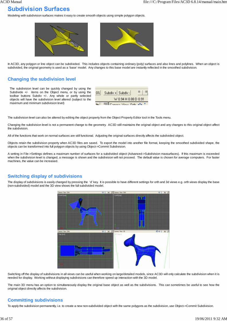
Modeling with subdivision surfaces makes it easy to create smooth objects using simple polygon objects.
In AC3D, any polygon or line object can be subdivided. This includes objects containing ordinary (poly) surfaces and also lines and polylines. When an object issubdivided, the original geometry is used as a ‘base’ model. Any changes to this base model are instantly reflected in the smoothed subdivision.
Changing the subdivision level
The subdivision level can be quickly changed by using theSubdivide +/- items on the Object menu, or by using thetoolbar buttons Subdiv +/-. Any whole or partly selectedobjects will have the subdivision level altered (subject to themaximum and minimum subdivision level)
The subdivision level can also be altered by editing the object property from the Object Property Editor tool in the Tools menu. Changing the subdivision level is not a permanent change to the geometry. AC3D still maintains the original object and any changes to this original object affectthe subdivision. All of the functions that work on normal surfaces are still functional. Adjusting the original surfaces directly affects the subdivided object. Objects retain the subdivision property when AC3D files are saved. To export the model into another file format, keeping the smoothed subdivided shape, theobjects can be transformed into full polygon objects by using Object->Commit Subdivision. A setting in File->Settings defines a maximum number of surfaces for a subdivided object (Advanced->Subdivision maxsurfaces). If this maximum is exceededwhen the subdivision level is changed, a message is shown and the subdivision will not proceed. The default value is chosen for average computers. For fastermachines, the value can be increased.
Switching display of subdivisionsThe display of subdivisions is easily changed by pressing the ‘d’ key. It is possible to have different settings for orth and 3d views e.g. orth views display the base(non-subdivided) model and the 3D view shows the full subdivided model.
Switching off the display of subdivisions in all views can be useful when working on large/detailed models, since AC3D will only calculate the subdivision when it isneeded for display. Working without displaying subdivisions can therefore speed up interaction with the 3D model. The main 3D menu has an option to simultaneously display the original base object as well as the subdivisions. This can sometimes be useful to see how theoriginal object directly affects the subdivision.
Committing subdivisionsTo apply the subdivision permanently, i.e. to create a new non-subdivided object with the same polygons as the subdivision, use Object->Commit Subdivision.
AC3D Manual file:///C:/Program Files/AC3D 6.8.14/manual/main.htm
36 of 57 19/06/2011 9:32 AM

ExamplesSubdivision works by dividing each surface and then smoothing the overall shape.An example – a simple box:
0 subdivision level
1 subdivision level
2 subdivision level
3 subdivision level
Note that the default surface type for a box isflat. Setting this to ‘Smooth’ and setting theobject property for ‘Crease angle’ to 180ensures that the object is fully smoothed.(Display of the surfaces has been switched offfor this picture)
These images show a simple cup shape that was formed by using Object->Revolve on a line. The number of segments was set to 6. The image on the rightshows this same object with subdivision level applied.
Hints and tips
AC3D Manual file:///C:/Program Files/AC3D 6.8.14/manual/main.htm
37 of 57 19/06/2011 9:32 AM

Although any polygon in AC3D can be subdivided,subdivision works best with quads (four point/sided surfaces)since they divide symmetrically.
A cube is a good starting point for many models since each face can be extruded and the vertices moved to form other shapes, whilst retaining a single closedobject with no holes. The block object is also a good base for building subdivided objects.
Using Extrude to add detailExtrude is the best way to add extra detail to a subdividedobject. These settings are recommended for extruding 3Dsubdivided shapes:
A simple way to add stronger defined edges to a model is toextrude with zero movement. This can be done by switchinginto extrude mode and simply clicking on the bounding box. The extrusion will be performed but no movement takes place.In the example here the left object is a cube with the topsurface extruded. The right object is a copy of this object butwith no subdivision level set – note that although it looks thesame as a normal cube, there are actually extra surfacesaround the edge of the top surface.
Display or hide subdivisions?This image shows a cube with the top surface selected. Notice how the bounding box is not located directly over theselected surface (as it would be with a non-subdividedobject). This is normal, since the bounding box surrounds theoriginal (non-subdivided) geometry. Switching off the display of subdivisions (press ‘d’) showswhy; the actual surface selected, in the original object is in aslightly different location because the subdivision causes theshape to change.
A similar effect can be seen in Vertex select-mode. Here, twovertices are selected – note how the selection shows aroundthe area of the original vertices. This is because it is theoriginal vertices that are affected; the subdivision is based ontheir positions.
Choosing the right subdivision level Subdividing an object by one level increases the number of surfaces in that object by (a minimum of) four times and each subsequent subdivision increases thisnumber by a factor of four. Each level of subdivision increases memory requirements and will have an effect on speed since there are many more polygons to bedrawn and processed.
The number of vertices and surfaces in asubdivided object can be view from the ModelInfo tool on the Tools menu:
For general use, level 2 gives a smooth appearance to objects whilst keeping polygon counts lower. Obviously, machines with large amounts of memory, fastprocessors and fast graphics accelerators can work with larger models more easily.
Advanced usersThe default maximum subdivision level in AC3D is 3. This can be increased in the advanced settings. You should be aware that any increase in subdivisionlevels increases the computational requirements.
AC3D Manual file:///C:/Program Files/AC3D 6.8.14/manual/main.htm
38 of 57 19/06/2011 9:32 AM

Each AC3D object can have one texture. A texture is set from the Object->Texture menu.
Setting a texture
Each AC3D object can have one texture applied to itssurfaces. After selecting an object (or objects), use the menuObject->Texture->Load Texture to set a texture. AC3D loads a number of different picture file formats astextures. These include .gif, jpeg etc. To view whichformats AC3D can load, see the load texture dialog.
Note that some export formats (or rather the programs that load the files) do not support all the texture file types that AC3D supports. You should ensure that youare using the correct format texture for the correct export file type e.g. .jpg or gif for VRML.
Changing the mappingTexture coordinates determine how a texture is mapped onto the surfaces of an object. All AC3D objects have default texture coordinates applied to them whenthey are created. A cube for example has mapping set so that one instance of the texture will appear on each face. Some external files have formats that do not contain texture coordinates and some AC3D operations may cause these coordinates to become disturbed; in thesecases it is necessary to remap the texture coordinates.
Changing the texture repeat and offsetsThe texture repeat and texture offset for an object can be modified in Object->Texture->Set texture repeat/offset. The texture repeat indicates the number of timesthe texture is to be fitted into that dimension.
Example: a cube with texturerepeats set to 1, 1 (the default):
Object->Texture->set-texturerepeats/offsets and repeatsset to 2, 2:
The texture offset determines how far across the texture the mapping should start.
AC3D Manual file:///C:/Program Files/AC3D 6.8.14/manual/main.htm
39 of 57 19/06/2011 9:32 AM

Texture repeat set to 1,1 andTexture offsets set to 0.5,0.5:
If more than one texture is required on a single object (e.g. a different image on each side of a cube), the object should be split up into parts (e.g. useSurface->Cut Away Object) and a different texture mapped on to each of the sub-objects. Alternatively, it is more efficient to create a single texture image (i.e. a single picture file containing all the required images) and use AC3D’s Texture CoordinateEditor tool to map parts of the object.
AC3D Manual file:///C:/Program Files/AC3D 6.8.14/manual/main.htm
40 of 57 19/06/2011 9:32 AM
This section describes AC3D’s integrated tools. Tools are accessed from the Tools menu. Other tools can be added to this menu via software plugins.
Model InformationThis displays information about the current model.
This shows the information for a single cube. Note that the total number of objects shown is actually two. This is because the ‘World’ object is included in thiscount. The internal world object is the top-level container object. This window can remain visible whilst other work continues, but if any changes occur to thecurrent AC3D model, the ‘refresh’ button must be pressed in order to update the displayed information.
Render
This tool is used to start up an external renderer (such as a Raytracer like Povray) or other linked program. See the rendering section for more information on howthis is configured.
Object HierarchyThis window shows the structure of the current model but also allows control over the structure of the hierarchy.
Clicking on one of the items in the list can select or unselect objects. This selection is sensitive to the current select mode being used. In Group- select mode, forexample, it is only possible to select top-level groups. To select individual objects, switch to Object -select mode (using the main AC3D control panel). The eye icon shows/controls visibility (similar to Hide/Unhide on the main AC3D control panel). The padlock icon controls/shows if an object is locked. A right click on an object item will reveal a popup menu:
This allows control over hiding, a more detailed properties viewer, editing object data and the option of moving an object to the head (start) or tail (end) of thechildren list.
AC3D Manual file:///C:/Program Files/AC3D 6.8.14/manual/main.htm
41 of 57 19/06/2011 9:32 AM

Object Property EditorObjects have properties that can be adjusted using the Object Property Editor. The crease angle and subdivision level can be adjusted by moving a slider andpressing a set button. Every AC3D object can have a URL (web link address) and text data attached to it. This is a string of text. This data is saved in the AC3Dfile, along with the object geometry information.
Objects exported in VRML files will have a link generated around them if a URL is present, and Povray objects can include object data text at the end of eachobject description (allowing custom Povray commands to be added). The Loc point defines the position of the centre of the object. This is the local origin of the object.
Texture Coordinate Editor
AC3D’s integrated Texture Coordinate Editor (TCE) allows full control over the texture coordinates that are applied to all surfaces in AC3D objects. To start the TCE select: Tools->Texture Coordinate Editor. To edit the texture coordinates of an object, select a single object, or surfaces from a single object (in the main AC3D windows). The TCE runs in conjunction withthe main AC3D program so it is possible to switch between the windows, selecting the surfaces and objects you wish to edit. Note that if a group object isselected (which has textured children) then nothing will appear in the TCE. In this case, switch to Object –select mode and select a single object. The surfaces selected in AC3D will appear in the TCE according to their texture coordinates. All AC3D primitive objects (those created from the control panel)have default texture coordinates. For example:
AC3D Manual file:///C:/Program Files/AC3D 6.8.14/manual/main.htm
42 of 57 19/06/2011 9:32 AM
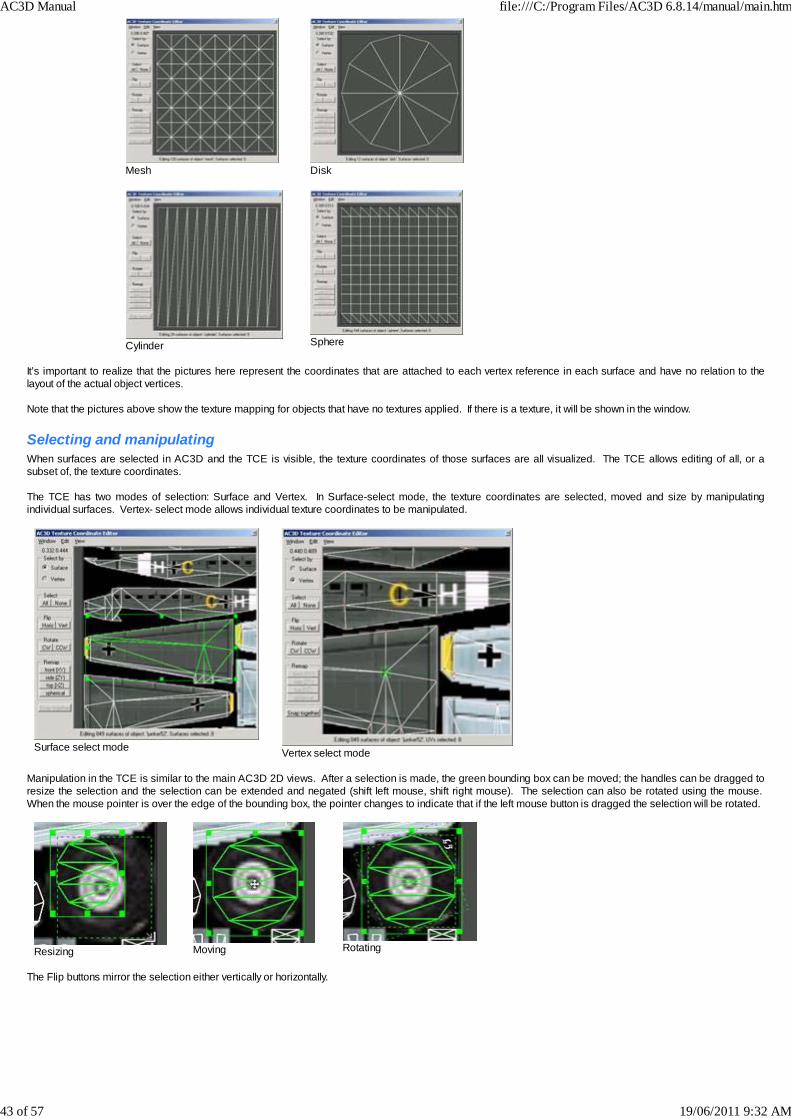
Mesh Disk
Cylinder Sphere
It’s important to realize that the pictures here represent the coordinates that are attached to each vertex reference in each surface and have no relation to thelayout of the actual object vertices. Note that the pictures above show the texture mapping for objects that have no textures applied. If there is a texture, it will be shown in the window.
Selecting and manipulatingWhen surfaces are selected in AC3D and the TCE is visible, the texture coordinates of those surfaces are all visualized. The TCE allows editing of all, or asubset of, the texture coordinates. The TCE has two modes of selection: Surface and Vertex. In Surface-select mode, the texture coordinates are selected, moved and size by manipulatingindividual surfaces. Vertex- select mode allows individual texture coordinates to be manipulated.
Surface select modeVertex select mode
Manipulation in the TCE is similar to the main AC3D 2D views. After a selection is made, the green bounding box can be moved; the handles can be dragged toresize the selection and the selection can be extended and negated (shift left mouse, shift right mouse). The selection can also be rotated using the mouse. When the mouse pointer is over the edge of the bounding box, the pointer changes to indicate that if the left mouse button is dragged the selection will be rotated.
Resizing Moving Rotating
The Flip buttons mirror the selection either vertically or horizontally.
AC3D Manual file:///C:/Program Files/AC3D 6.8.14/manual/main.htm
43 of 57 19/06/2011 9:32 AM
Flipped vertically Flipped horizontally
Remapping the selection The ‘Front’, ‘Side’, ‘Top’ buttons ‘project’ the texture onto the surfaces in the specified axis. The bounding size of the selected surfaces determines the boundaries of the mapping. The‘spherical’ button causes the texture coordinates to be ‘wrapped’ around selected surfaces.
It is possible that after starting the TCE and selecting anobject the window appears blank. It is likely that theobject has zero value texture coordinates e.g. eachsurface-vertex reference has 0.0, 0.0 as a coordinate. Ina case like this, a ‘Select all’ in the TCE would revealthat all of the coordinates are set to 0, 0. In this case, you will need to make sensible coordinatesfor your model, probably in groups. Do this by selectinga number of surfaces (from within AC3D) and using theremap buttons to assign a mapping to the texturecoordinates. You can then reposition and size thesurfaces in the TCE and map them onto a texture.
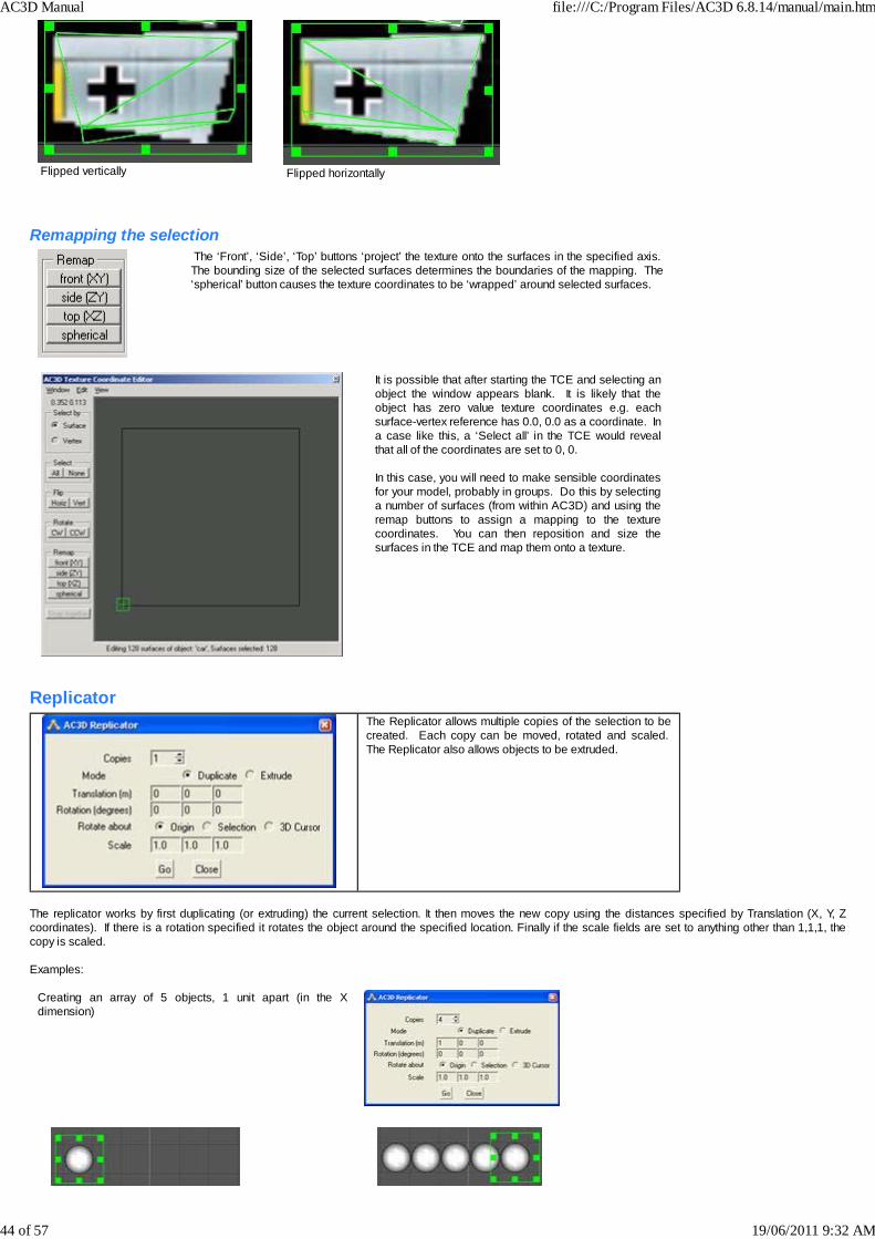
Replicator
The Replicator allows multiple copies of the selection to becreated. Each copy can be moved, rotated and scaled. The Replicator also allows objects to be extruded.
The replicator works by first duplicating (or extruding) the current selection. It then moves the new copy using the distances specified by Translation (X, Y, Zcoordinates). If there is a rotation specified it rotates the object around the specified location. Finally if the scale fields are set to anything other than 1,1,1, thecopy is scaled. Examples:
Creating an array of 5 objects, 1 unit apart (in the Xdimension)
AC3D Manual file:///C:/Program Files/AC3D 6.8.14/manual/main.htm
44 of 57 19/06/2011 9:32 AM

Creating four copies, scaling each time:
Extruding a ‘horn’ shape from a single ellipse.
Creating a single step for a spiral staircase by extruding arectangle
Use the replicator to duplicate the steps in a spiral pattern.
Create Text The Create Text tool, which is to be found in the Toolsmenu, generates 2D and 3D objects from TrueType fonts.
AC3D Manual file:///C:/Program Files/AC3D 6.8.14/manual/main.htm
45 of 57 19/06/2011 9:32 AM

This image shows the same text in Outline, Solid, Extrudedand Beveled type.
The font size specifies the maximum unit height of the text. The font detail (1 to 10) controls the number of vertices per letter. The greater the detail, the moresurfaces and vertices will be in the resultant AC3D objects.
Align ObjectsThis allows objects to be repositioned relative to one object. Select a single object and then shift-select others. On pressing ‘Align’, the first object is used as thereference object.
Position 3D cursor The 3d cursor specifies a position in 3D space. It is useful when creating objectssince it specifies the ‘missing’ axis. For example, when a sphere is being drawnin the front window, the mouse movements specify the X and Y position of thesphere; the Z position comes from the location of the 3D cursor. The default position of the 3D cursor is at the origin 0, 0, 0.
Many users find that they never need to adjust this, but it can be useful to change its position, when working on large models away from the origin.
AC3D Manual file:///C:/Program Files/AC3D 6.8.14/manual/main.htm
46 of 57 19/06/2011 9:32 AM

The paletteThe scrolling window of buttons near the bottom of the control panel represents the palette of colors/materials available. The default color for an object is paletteentry 1 (usually white). The colored buttons are pressed to change the material on the currently selected objects/surfaces. Setting the material of surfaces works in all selection modes,but for a surface to change color in Vertex mode it must have all vertices selected. Note that the color on the palette button represents the diffuse color for thatmaterial. New palette buttons are appended to the list when a file containing extra materials is loaded. When surfaces have a texture as well as a material, that material can affect the way the texture appears. To make a texture appear as the original colored imagethe surface color should be white. To find the material index of an existing polygon, select that surface and the message at the bottom of the AC3D window will display the material number.
Editing Palette entries
Pressing the right mouse button on a palette button pops upa menu. The options are to edit a color, select all surfaceswith that material or add a new material. A copy of theselected material will be added to the end of the list. Pressing the colored button brings up a system colorselection. Pressing the ‘+’ button next to an item expands the item sothat the numeric values of the Red, Green and Bluecomponents can be altered with sliders.
The material window allows various attributes of the material to be altered
Diffuse This is essentially the main color of the material. The exact shade shown on a model depends on theamount of light available to the surface
Ambient Ambient color works with the diffuse to affect the overall color of a surface, but is not sensitive to the amountof light on that surface.
Emissive Setting this can make a surface appear to be giving off light. This may be used, for example, to give a lightblue glow to a spaceship’s engine. (No actual light is emitted from surfaces with an emissive color set.)
Specular The specular quality defines the color and brightness of highlights. This works in conjunction with Shininess.
Shininess A high value means that highlights will be smaller and less scattered across the surfaces.Transparency Transparency can be useful to for making a surface look like glass. Transparency is supported in the palette
but for purposes of speed the surfaces are not sorted when they are rendered into the views.
If the ‘real-time update’ option is selected, any 3D view windows are redrawn every time a change is made to the material.
AC3D Manual file:///C:/Program Files/AC3D 6.8.14/manual/main.htm
47 of 57 19/06/2011 9:32 AM

An AC3D file (usually named <something>.ac) is a text file describing the geometry of a model. AC3D files retain all available information about a model builtwith AC3D e.g. textures, surface settings, materials, object data etc. Other file formats exported by AC3D may not retain all of this information. Models shouldalways be saved in this format to ensure that no detail is lost. Developers can view a description of the file format on the AC3D website. AC3D files are loaded by selecting File->Open. This will replace the current model. To load models in addition to the current model, use File->Merge. A list of the most recently opened files appears on the File menu. Selecting one of these causes it to be loaded.
Importing other formatsSee the File->Import menu for a list of file types that AC3D can import.Extra Import/Export plugins allow AC3D to handle more file formats. Check the AC3D website for details of additional plugins. The following formats may be useful for importing your own model data.
Triangle filesThe format of triangle files is: each line contains 9 floating point numbers and one hex value e.g.: 0.0 0.0 0.0 1.0 0.0 0.0 1.0 1.0 0.0 0xffffff represents 3 vertices ofa triangle. Hex value is 0xRRGGBB col - in this case white duplicate vertices are aggregated when loaded.
Vector filesThis is another simple format for importing 2D vector data. Each line should consist of a number of vertices followed by the same number x/y coordinate pairs e.g.3 0.5 0.5 2.5 2.5 10 5This represents a line with 3 vertices (0.5, 0.5) (2.5, 2.5) (10, 5)
Exporting filesAC3D can generate output files for many different formats. Support for extra file formats can be added by installing additional AC3D plugins. See File->Exportfor a list of the output files supported. Several are mentioned here.
3D Studio (3ds)3D studio files are used in 3D Studio Max 3D software. This is a long established binary format which is supported by a lot of third party software. Note thatobjects with > 1 material will be split into separate meshes within the 3DS file.
VRML 1VRML is an ASCII geometry file specification used for web graphics. VRML files may be viewed from within any web browser that has an appropriate plugininstalled e.g. Cortona http://www.parallelgraphics.com/products/cortona/. AC3D Object URLs (set from the object data dialog) are used so that objects will be selectable in the appropriate browser. The output of normals and textures canbe switched on/off in the File->Settings window.
VRML 2VRML 2 is a geometry description web file format which also allows animation and some other powerful constructs. See VRML 1 for a suitable browser plugin. Output of normals and textures is switchable via Settings.
VRML2 ProtoThis form of VRML2 output exports objects into a VRML prototype. This can be used when compositing larger models where each object may be stored in anindividual file and a single file controls the locations of individual instances.
DIVEDive is a Virtual Reality system. The Dive generation will include the object data (if you have input any); this is usually TCL code. If an object has a URL then theobject will be a dive gateway. See http://www.sics.se/dive for more info about the Dive VR system.
MASSIVEMassive is a distributed VR tele-conferencing system written by Chris Greenhalgh at Nottingham University in the UK. It runs on SGI and Sun platforms. For moredetails, see: http://www.crg.cs.nott.ac.uk/~csm/massive.html
RENDERMANThese files are used in a raytracer. This allows detailed images with accurate lighting, shadows and reflections to be created from a 3D model. There are anumber of Renderman- compatible renderers available. The eye viewpoint is defined by your view position in the primary 3D window (approx). Note that lines willnot be output. Any polygons that need triangulating (breaking up into triangles) will be triangulated.
POV-RayPOV-Ray is a very popular raytracer; see www.povray.org for more information. The eye viewpoint is defined by the view position in the 3D window. In Spin modethe viewpoint will be approximate; for a more accurate viewpoint position switch to walk-mode in the 3D window.
AC3D Manual file:///C:/Program Files/AC3D 6.8.14/manual/main.htm
48 of 57 19/06/2011 9:32 AM

The color palette is output at the top of the file; each entry has the same number as the AC3D material. The properties can be altered easily to provide differentsurface types and textures (some #includes can be added at the top of the file to get external definitions). The light is output at the end of the file. The light’sposition is the same as the viewers. The POV-Ray output is based on triangles; lines will be ignored and polygons with more than three vertices will betriangulated automatically. The Object data text, specified in Tools->Object Property Editor, can be used to attach information to objects which is then inserted into the POV-Ray file. ‘Useobject data in POV files’ in the main AC3D File->Settings must be ticked so that this text is inserted into the file. A POV-Ray include command may be inserted into the setting ‘POV header’ e.g. #include "glass.inc". See the Rendering section for an example of using POV-Ray.
Triangle filesSee loading triangle files for a description of this format. This format is very simple and is easy to parse.
Object LibraryThe object library is accessed from the File menu and canhelp organize and maintain a structured set of modelcomponent objects. Objects may be added and removed from the library. Forexample, these ‘components’ may be electronic parts, kitchenunits, molecule models etc. Loading a single object from the library can be repeated tomake multiple copies of the same object. Note that the 3D position at which the object is saved will beits location when it is loaded again from the library. To add an object to a library, select it and press “Store”. Take care when replacing objects, as the object that iscurrently selected in AC3D will overwrite the file stored on thelibrary.
AC3D Manual file:///C:/Program Files/AC3D 6.8.14/manual/main.htm
49 of 57 19/06/2011 9:32 AM

The "Render" tool in the tools menu can be configured to automatically launch an external renderer. This allows generation of high-resolution images withshadows, reflections, transparency and other effects.
The output file type is set from the ‘Output file type’ pull-down menu. The file types listed here are all of the file-types that AC3D can export (extra file-types mayhave been added using plugins). The ‘Output filename’ specifies the name of a file that the model will be generated into. The ‘Render program’ specifies the program that will start after the file is written. The ‘Render Parameters’ are appended to the command line that it executed to start the render program. If a ‘%s’ is specified in the render command, it will bereplaced by the render filename.
A POV-Ray examplePOV-Ray is a very popular ray-tracer - see www povray.org.
This example shows a very simple modelconsisting of a mesh, a sphere and a cube thathas been divided a couple of times (withSurface->Divide), then had a Surface->Make Holeoperation. There is also an extra light present inthe model.
The sphere has had a pov texture specified using the Tools->Object Property Editor (the appearance of the object in AC3D will be unaffected by this):
The settings in File->Settings were:
Pressing the Render button in the Render Tool gives:
The Povray exporter supports bitmap-textured objects. Ensure that the formats of the texture picture files used are compatible with POV-Ray.
AC3D Manual file:///C:/Program Files/AC3D 6.8.14/manual/main.htm
50 of 57 19/06/2011 9:32 AM

Space Mouse supportAC3D supports 3Dconnexion’s 3D navigation hardware. There are a number of different motion controllers availablefrom 3Dconnexion, all are compatible with AC3D. A 3D mouse can be used in the AC3D’s orthographic (2D) views andin 3D views (in both spin and walk modes). In AC3D’s Orth/2D views, a 3D mouse will pan (move left/right/up/down) and zoom. In a 3D view in spin-mode, the 3Dmouse will act as if the selection is being handled (this is commonly called object-navigation in many CADapplications). In a 3D view in walk-mode, the 3D mouse is used to walk/fly around the scene as if the camera is beingcontrolled (commonly called camera-mode navigation). AC3D can be configured for both user preferences for zooming. Zooming can be performed either when the 3D mouseis pulled up/down or when it is pushed forwards/backwards. The following image shows a configuration dialog from aSpaceNavigator. In AC3D, this is shown when the right button on the SpaceNavigator device is clicked.
In this image, zooming is set for up/down on the SpaceNavigator. There are two 3D mouse related settings in AC3D which can be altered. See menu File->Settings->Advanced:
These settings affect the way the SpaceNavigator controls rotation. For up/down zoom direction, the rotating is done when the 3D mouse is twisted left/right. For forward/backward zooming, the rotation is controlled by tilting the 3Dmouse left and right. If zooming is set to up/down, as in the SpaceNavigator dialog image above (green arrows), these two settings should be left un-ticked. If the 3D mouse zoom isset for forward/backward (blue arrows), tick these settings. The left device button on the space mouse is set to ‘Fit’. This moves the display focus to the center of the current selection. An example; if you are navigating inspin-mode and wish to work on another object or part of an object, change the selection and press the fit button. The right device button is set to bring up thesettings dialog. Pressing this button again dismisses the dialog. For more information on 3Dconnexion’s devices, see www.3dconnexion.com.
PluginsPlugins add extra functionality and additional file format support to AC3D. Plugins files are usually named <something>.p and reside in the Plugins folder withinthe AC3D installation. Additional tcl files in the same folder may also provide user-interfaces and scripting for use with some plugins. Plugins are automatically loaded when AC3D starts. The console displays the progress of loading plugins and will show any errors that occur. It is important thatplugins are designed to run with the correct version of AC3D, or they may fail to load.
AC3D Manual file:///C:/Program Files/AC3D 6.8.14/manual/main.htm
51 of 57 19/06/2011 9:32 AM

To find out more about the plugins that are currently installed, use Help->AboutPlugins. Selecting each plugin line brings up a description and any associatedinstructions for the plugin.
Performance tips Rendering more polygons takes more time. As larger and more detailed objects are edited, the rendering will take longer. Here are some tips to help edit largermodels more effectively.
· Switch to wireframe viewing. This is faster to render than filled graphics.· Use object hiding and locking. This reduces the graphics load.· Edit in only one maximized view. This prevents all views from being updated every time a change is made.· If surfaces can only be viewed from one side (e.g. they are outer surfaces of a closed object such as a box), set them to single-sided. This is slightly
faster to draw.· Switch on ‘interactive-wireframe’ in both the Orth and 3d menus. This temporarily sets the view to wireframe when being panned or zoomed using the
mouse. Wireframe usually renders faster than filled polygons.· The ‘Interactive Wireframe’ switches, located on the main Orth and 3D menus, will switch the views into wireframe for manipulations.· When using surface-subdivision keep the subdivision preview level set to 1 or 2 when working on the object. Switching off the display of subdivisions
will also speed up interaction.· Use Object->Reduce to reduce the number of vertices/polygons in an object.
Key-presses Key shortcuts for menu items are shown on the menus. Other keys can be used:
In orthographic (2D) windows:
Key Function
Cursor-keys move view
Shift-Cursor move view faster
Control-up zoom in
Control-down zoom out
Shift-Control-up zoom in with larger step
Shift-Control-down zoom out with larger step
Alt-Cursor move background image
Alt-shift-cursor up/down scale background image
Backspace/Delete delete current selection
Space maximize or minimize the current view
t toggle textures
o set select mode to OBJECT
v set select mode to VERTEX
s set select mode to SURFACE
m set drag mode to MOVE
r Set drag mode to ROTATE
e set drag mode to EXTRUDE
f fit selection to window
control-f fit selection to all views
g toggle grid
h hide selected objects
z zoom in
x zoom out
Space maximize/minimize view
Some of the keys for the 3D window have an equivalent menu item in the 3D menu.
In 3D views:
Key Function
w wireframe/filled toggle
t toggle textures
g toggle 3d grid
f fit to window/centre spin view around the selection
AC3D Manual file:///C:/Program Files/AC3D 6.8.14/manual/main.htm
52 of 57 19/06/2011 9:32 AM

Space maximize/minimize view
In the 3D window, the cursor-keys spin the model in 'spin-mode'. In Walk mode, they control the viewpoint in a similar way to 'Quake' and other games e.g. left,right, forward, back, alt-up/down move up/down, control-up/down tilt.
Preferences/settingsThe settings in File->settings are saved automatically when you exit AC3D. This automatic saving can be switched off from the settings window. Settings must besaved with this set to ‘off’ for the change to be remembered. Under Mac/Unix, the settings are saved to $HOME/.ac3dprefs. Under Windows, they are saved to the user’s home directory as ac3dprefs.txt.
AC3D Manual file:///C:/Program Files/AC3D 6.8.14/manual/main.htm
53 of 57 19/06/2011 9:32 AM

Third-party pluginsThere are a number of additional plugins that add extra functionality to AC3D. Some are supplied with AC3D and are described here, others are available via theAC3D forum pages – see the website for more information
GreebleFrom SuperColdMilk, this excellent AC3D plugin makes it easy to add detail to your models.
Greeble is an AC3D plugin that adds greebles to existing geometry. Wikipedia defines a greeble thus: “…a small piece of detailing added to break up thesurface of an object to add visual interest to a surface or object, particularly in movie special effects." Greebles are placed in a separate object from the base object. Your base geometry is not modified. The Greeble user-interface is accessible from the AC3D Tools menu.
There are many options, the parameters are described here.
Parameter Usage
Beveling If checked, bevels will be placed on selected surfaces prior to adding greebles. This is often used to get a discontinuous"raised floor" effect.
Bevel frequency % The frequency with which bevels are applied to surfaces. For instance, a value of 75% means roughly 3/4 of the selectedsurfaces will be beveled.
Bevel minimum height %Bevel maximum height %
The minimum/maximum height that a bevel will be raised on a given surface (the actual value per surface is random).Beveling uses a formula that takes the area of the underlying surface into account. This number may exceed 100%.
Bevel minimum indent %Bevel maximum indent %
The distance from the edge of a surface that a bevel will start. Specify zero to have bevels at the very edge of a surface.
Bevel division frequency % The frequency with which bevels will be split into 2, 3, or 4 separate bevels. If a bevel is split, the split between 2, 3, or 4bevels is random. This feature only works on quads, not triangles.
Greebling If checked, greebles will be placed either on the tops of bevels, or directly on the tops of surfaces where no bevels exist.
Greeble frequency % The frequency with which greebles are applied to surfaces. For instance, a value of 75% means roughly 3/4 of theselected surfaces will be greebled.
AC3D Manual file:///C:/Program Files/AC3D 6.8.14/manual/main.htm
54 of 57 19/06/2011 9:32 AM

Minimum greebles per surfaceMaximum greebles per surface
The number of greebles that will be applied to each surface.
Greeble minimum height %Greeble maximum height %
The raised height of each greeble. Greeble heights default to the surface area of the underlying surface. This numbermay exceed 100%.
Greeble minimum size %Greeble maximum size %
The size of each greeble as it is spread on the surface. 100% means the greeble will completely cover the surface.
Greeble rotation degrees Greebles are randomly rotated when placed; this value dictates the increment (in degrees) which a greeble may berotated, from 0 to 90.
Random seed A seed for the randomizer used to determine greeble placement. Use a number here for consistent results betweengreeble runs on the same objects, or specify one (1) for a number based on the current date/time.
Use custom greebles If checked, custom greebles will be located and used (if present). See the "Custom greebles" section below.
Use standard greebles with custom If custom greebles are found and this box is checked, the custom greebles will be combined with standard greebles. Ifthis box is not checked, standard greebles will not be used unless there were no custom greebles found.
Maintain custom greeble aspect If checked, custom greebles will not be distorted to conform to the underlying surface. Use this for greebles where youwish to maintain their current width/depth/height aspect ratios.Note that this works best when placing greebles on relatively square/rectangular objects. When placing un-distortedgreebles on triangles or skewed polygons, they may tend to gravitate toward the weighted center of the polygon ratherthan.
Greebles in separate objects If checked, each greeble/bevel will be created in its own separate object. All greebles are then grouped into a singleAC3D group.Note that this can cause significant slowdowns if you end up with thousands of greebles/bevels in separate objects.
Realtime updates This feature provides you with an interactive preview, directly on your selected surfaces, of what your generated greeblewill look like. The greebles will be updated as you tweak/change variables.While realtime preview is active, you will not be able to interact with your model. You may go in and out of realtimepreview to rotate/scroll your model view to get a different perspective on the greeble-in-progress.Note that if you manually type values in fields, the realtime preview does not update - only when you use the numericscrolls or the checkboxes does the preview update.Once you click the "Create greebles" button, the actual greebles are generated, and realtime preview is disabled.
Save settings to greeble Data Enable this feature to write a summary of greeble settings to the newly created greeble object. Handy for seeing how youinitially generated a greeble object. Use the AC3D object property window to see the contents of the Data field.Each textual setting is prefixed by "//", which should make this POV-Ray-safe.
Standard greebles
By default, there are 4 types of greebles, shown here. These greebles are stretched, rotated and scaled inaccordance with the underlying surface.
Custom greebles Use custom greebles where the standard set does not meet your needs. Custom greebles are merely AC3D objects. To make an object a custom greeble, edit the object's Data property (F9 in Object mode) and type"//CUSTOM_GREEBLE" (without the quotes) at the beginning of any line in the text box. Make sure you type in all-caps as shown, and do not enter any spaces. (NOTE: A future release may make this a friendlier process). You may define as many custom greebles as you like. If you have a set that you like to use, you could save them to their own file and load that file into whicheverdocument you'd like to use them. Also, greebles should point "up" along the Y axis. Basically, the view of your greeble in the "top" view is the way the greeble will be applied to the target surfaces. Once you have your custom greebles created, make sure the "Use custom greebles" checkbox is checked. Below is an example using custom greebles. The cylinder and half-sphere have been defined as custom greebles. I have created a greebled cube with a mixtureof custom and standard greebles.
AC3D Manual file:///C:/Program Files/AC3D 6.8.14/manual/main.htm
55 of 57 19/06/2011 9:32 AM
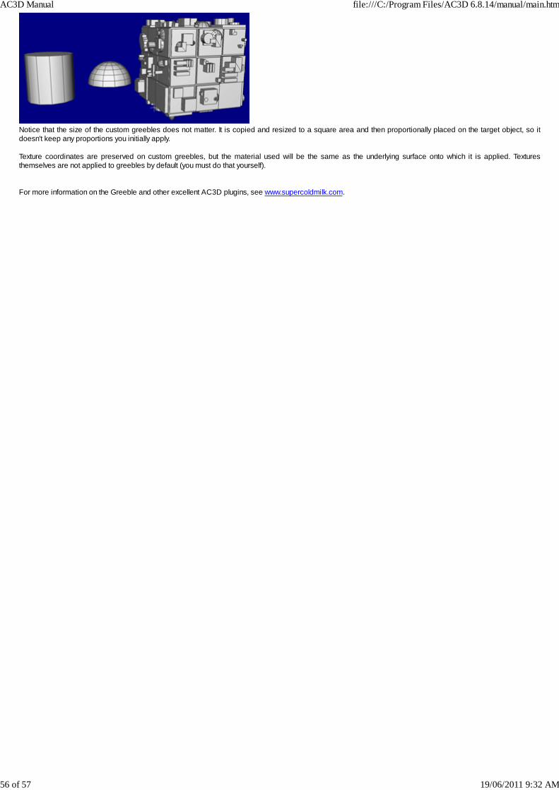
Notice that the size of the custom greebles does not matter. It is copied and resized to a square area and then proportionally placed on the target object, so itdoesn't keep any proportions you initially apply. Texture coordinates are preserved on custom greebles, but the material used will be the same as the underlying surface onto which it is applied. Texturesthemselves are not applied to greebles by default (you must do that yourself). For more information on the Greeble and other excellent AC3D plugins, see www.supercoldmilk.com.
AC3D Manual file:///C:/Program Files/AC3D 6.8.14/manual/main.htm
56 of 57 19/06/2011 9:32 AM

© 2011 Inivis LimitedAll rights reserved. No part of this publication may be reproduced or transmitted in any form or by any means, electronic or mechanical, including photocopying,recording or storing in a retrieval system, or translated into any language in any form without the prior written permission of Inivis Ltd. Software licenseThe software described in this document is furnished under a License Agreement, which is included with the product. This agreement specifies the permitted andprohibited uses of the product. Licenses and trademarksInivis ltd., the Inivis logo, AC3D and the AC3D logo are trademarks of Inivis ltd. All other product names and any registered and unregistered trademarksmentioned in this manual are used for identification purposes only and remain the exclusive property of their respective owners. Iniviswww.inivis.com
AC3D Manual file:///C:/Program Files/AC3D 6.8.14/manual/main.htm
57 of 57 19/06/2011 9:32 AM