Version 2017.06A (02 June 2017) - Mackay Regional Council · MRC D20 Drawings and Documentation...
62
Version 2017.06A (02 June 2017)
Transcript of Version 2017.06A (02 June 2017) - Mackay Regional Council · MRC D20 Drawings and Documentation...

Version 2017.06A (02 June 2017)

Page | 1
MRC D20 Drawings and Documentation Guidelines >
Version 2017.06A (02 June 2017)
Purpose ............................................................................................................................................. 5
General Drawing Requirements ........................................................................................................ 5
2.1 Minimum Drafting Requirements ................................................................................................ 5
2.2 Size of Plan ................................................................................................................................ 6
2.3 Order of Drawings ...................................................................................................................... 6
2.4 Scales ........................................................................................................................................ 6
2.5 Title Block .................................................................................................................................. 7
2.6 Council Drawing Numbers .......................................................................................................... 7
2.7 Levels and Co-ordinates............................................................................................................. 7
2.8 Dimensioning on Plans ............................................................................................................... 8
2.8.1 General ............................................................................................................................... 8
2.8.2 Chainages and Offset Dimensions ...................................................................................... 8
2.9 Line Styles and Fonts ................................................................................................................. 8
2.10 Accuracy .................................................................................................................................... 8
2.11 Drawing Layers .......................................................................................................................... 8
2.12 General Survey Requirements ................................................................................................... 8
2.12.1 Work must be carried out by a Registered Surveying Person .............................................. 8
2.12.2 Survey Codes ...................................................................................................................... 8
2.12.3 Required Data / Projection .................................................................................................. 8
2.12.4 Accuracy Specifications for Conventional Instrument Surveys ............................................ 9
2.12.5 Accuracy Specifications for GPS Surveys ........................................................................... 9
2.13 Amendments/Revisions .............................................................................................................. 9
Development Project “Operational Works” Drawing Requirements .................................................... 9
3.1 Project Drawing Requirements ................................................................................................... 9
3.1.1 Locality Plan ........................................................................................................................ 9
3.1.2 Layout/Staging Plan .......................................................................................................... 10
3.1.3 Earthworks Plan ................................................................................................................ 10
3.1.4 Roadworks and Drainage Plans ........................................................................................ 10
3.1.5 Longitudinal Sections of Roads ......................................................................................... 11
3.1.6 Detail Plan of Intersection and Cul-de-Sac ........................................................................ 11
3.1.7 Standard Cross section ..................................................................................................... 11
3.1.8 Cross sections of Roads ................................................................................................... 12
3.1.9 Longitudinal Section of Drainage Lines ............................................................................. 12
3.1.10 Landscape Plan or Streetscape Plan ................................................................................ 12
3.1.11 Site and Layout ................................................................................................................. 12
3.1.12 On-Street Works ............................................................................................................... 13
3.1.13 Traffic Islands and Roundabouts ....................................................................................... 13
3.1.14 Public Open Space............................................................................................................ 13

Page | 2
MRC D20 Drawings and Documentation Guidelines >
Version 2017.06A (02 June 2017)
3.1.15 Services Plan .................................................................................................................... 14
3.1.16 Stormwater Catchment Plan/Drainage Calculations Tabulations ....................................... 14
3.1.17 Miscellaneous Details ........................................................................................................ 15
3.1.18 Erosion and Sediment Control Strategy ............................................................................. 15
3.1.19 Sewerage Reticulation ...................................................................................................... 15
3.1.20 Water Reticulation ............................................................................................................. 16
3.2 Development Projects “Operational Works” Submissions ......................................................... 16
Council Project “For Construction” Drawing Requirements .............................................................. 16
4.1 General .................................................................................................................................... 16
4.2 Council Capital Works – Urban................................................................................................. 17
4.2.1 Cover sheet, locality plan and drawing index ..................................................................... 17
4.2.2 General Arrangement and Control line Set out .................................................................. 17
4.2.3 Layout Plan(s) ................................................................................................................... 17
4.2.4 Levels plan(s) .................................................................................................................... 18
4.2.5 Stormwater drainage and services plan(s) ........................................................................ 18
4.2.6 Signs and pavement marking plan(s) ................................................................................ 19
4.2.7 Streetscape / landscape plan(s) ........................................................................................ 20
4.2.8 Irrigation plan(s) ................................................................................................................ 20
4.2.9 Street works details plan ................................................................................................... 20
4.2.10 Stormwater drainage details plan ...................................................................................... 20
4.2.11 Levels tables plan(s) ......................................................................................................... 21
4.2.12 Street long section plan(s) ................................................................................................. 21
4.2.13 Pavement details plan ....................................................................................................... 21
4.2.14 Cross sections plan(s) ....................................................................................................... 21
4.2.15 Stormwater drainage long sections plan(s) ........................................................................ 22
4.2.16 Stormwater drainage calculations table plan(s) ................................................................. 22
4.2.17 Stormwater drainage catchment plan ................................................................................ 22
4.2.18 Lighting plan(s) .................................................................................................................. 22
4.2.19 Water Reticulation plan(s) ................................................................................................. 23
4.2.20 Structural plan(s) ............................................................................................................... 23
4.2.21 Erosion and Sediment Control Notes ................................................................................ 23
4.2.22 Safety in Design Risk Register .......................................................................................... 23
4.2.23 Additional notes and possible variations to the above list .................................................. 23
4.2.24 Set out points and set out files .......................................................................................... 24
4.3 Council Capital Works – Rural .................................................................................................. 24
4.3.1 Cover sheet, locality plan and drawing index ..................................................................... 24
4.3.2 General Arrangement and Control line Set out .................................................................. 24
4.3.3 Plan and Long Section(s) .................................................................................................. 25
4.3.4 Type Cross Sections, Set out Tables, Access Details, Notes (possibly multiple plans) ...... 26
4.3.5 Intersection details plan(s) ................................................................................................. 26
4.3.6 Roadwork details plan ....................................................................................................... 26

Page | 3
MRC D20 Drawings and Documentation Guidelines >
Version 2017.06A (02 June 2017)
4.3.7 Levels tables plan(s) ......................................................................................................... 26
4.3.8 Cross sections plan(s) ....................................................................................................... 27
4.3.9 Stormwater Drainage Cross Sections and Details ............................................................. 27
4.3.10 Erosion and Sediment Control Notes ................................................................................ 27
4.3.11 Safety in Design Risk Register .......................................................................................... 27
4.3.12 Additional notes and possible variations to the above list .................................................. 27
4.3.13 Set out points and set out files .......................................................................................... 28
4.4 Council Capital Works “For Construction” Plan Certification for Issue....................................... 28
“As-Constructed” Drawings ............................................................................................................. 29
5.1 General .................................................................................................................................... 29
5.2 “As-Constructed” Survey Requirements ................................................................................... 30
5.3 Registered Engineer’s Certification .......................................................................................... 30
5.4 Drawing Format ........................................................................................................................ 30
5.5 Drawing Content Requirements ................................................................................................ 31
5.6 Asset Register (Development Projects Only) ............................................................................ 31
5.7 Asset Design As Constructed (ADAC) XML Submission (Council Projects Only) ..................... 32
5.8 Submission of As Constructed Data Workflow .......................................................................... 32
5.8.1 As Constructed Plan and Asset Delivery Workflow for Contract and Donated Asset Delivery 33
5.8.2 As Constructed Plan and Asset Delivery Workflow for Internally Delivered Asset Delivery 34
Documentation ................................................................................................................................ 35
6.1 Development Projects Design Report ....................................................................................... 35
6.2 Capital Works Design Report ................................................................................................... 36
6.3 “As-Constructed” Documentation ............................................................................................. 36
6.3.1 Buildings and Site Improvements ...................................................................................... 36
6.3.2 Reservoirs, Water and Sewage Treatment Plants, Sewage and Water Pump stations ...... 37
6.3.3 Artificial Wetlands .............................................................................................................. 39
6.3.4 Stormwater quality improvement devices (SQID) .............................................................. 39
Annexure A Design Certification Report for Development Projects ....................................................... 40
Annexure B Design Report Specific Details for Development Projects.................................................. 56
Annexure C Example of Registered Surveying Person’s Certification of “As-Constructed” Works ......... 58
Annexure D Asset Register for Development Projects .......................................................................... 60
Page | 4
MRC D20 Drawings and Documentation Guidelines >
Version 2017.06A (02 June 2017)
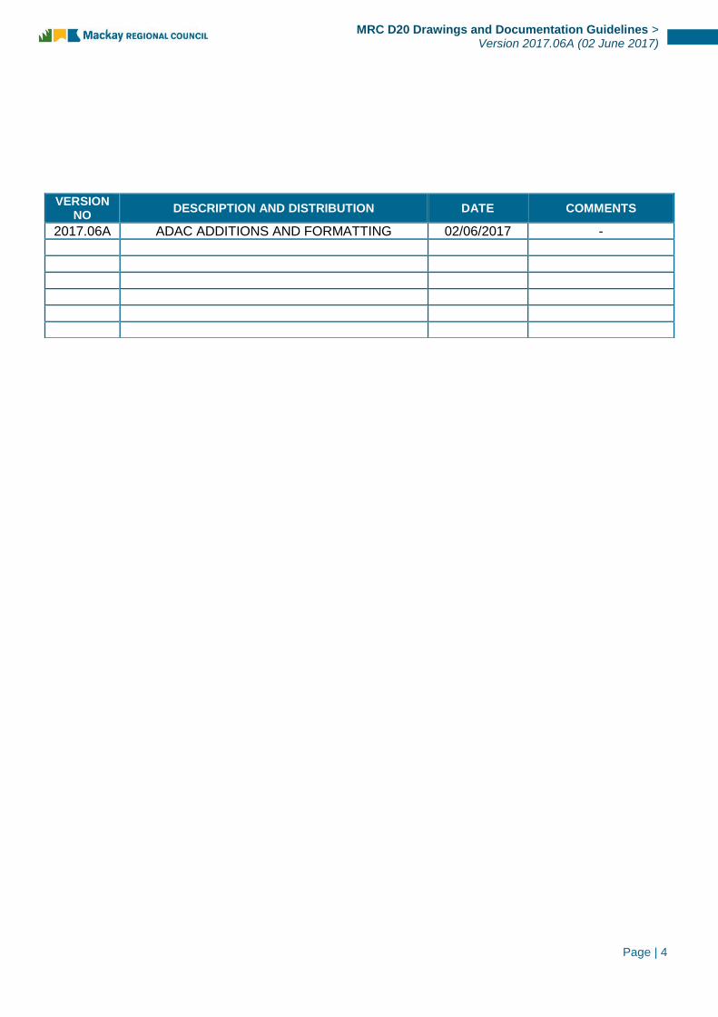
VERSION NO
DESCRIPTION AND DISTRIBUTION DATE COMMENTS
2017.06A ADAC ADDITIONS AND FORMATTING 02/06/2017 -

Page | 5
MRC D20 Drawings and Documentation Guidelines >
Version 2017.06A (02 June 2017)
This Guideline sets out the requirements for drawings and documentation associated with infrastructure managed by Mackay Regional Council.
Drawings serve three main functions, which correspond to the different phases of a project:
(a) Detailing a design proposal and for design approval
(b) Documenting construction requirements
(c) Recording the actual works constructed
As a project progresses from one phase to another, drawings will be revised and identified according to the status of the project. Most of the requirements for the drawings will be common to all phases, however, there will be specific requirements applicable to only one or two phases (e.g. Detailing of “As-Constructed” information). These drawing guidelines have been set out to cover the general requirements for all drawings, followed by separate sections specifying requirements which may be unique to a particular phase.
Design drawings shall be definitive and clearly set out so that the project can be readily understood, specified for construction and satisfactorily built.
The information shown on the drawings shall be logically collected on discrete sheets to avoid excessive cross-referencing between sheets.
Drawings should not be overcrowded with information and should not rely on colour printing or colour wash to impart information. They shall be clear and legible and prepared in consistent lettering and style.
The extent of the works to be constructed shall be clearly defined. Drawings shall differentiate between existing features, new construction and future works, by:
a) Using separate layers for existing, new and future works on electronic drawings
b) Using different line types for existing, new and future works
c) Showing the limits of work, including stage boundaries and location and details for joining new
works to existing
d) Identify existing features and identifying structures that are to be removed or replaced
e) Adding textual notes to identify existing or future works.
Drawings should be suitable for black and white printing and reduction to A3 paper size without loss of clarity.
Drawings which contain colours, shading or close hatch patterns are not acceptable given that printing these plans may render them illegible or reduce definition of details.
Unless approved otherwise, all drawings shall be provided in electronic PDF and DWG formats using AutoCAD software or an approved equivalent. Although drawings are created electronically, their most common use will be hard copy format and it is essential that drawings are legible and information interpretable when printed in black and white.

Page | 6
MRC D20 Drawings and Documentation Guidelines >
Version 2017.06A (02 June 2017)
Council will not accept drawings that do not meet these drafting guidelines. Drawings copied from other works will not be accepted. All drawings shall be clearly referenced with notations and tabled as appropriate.
All plans shall be drawn in metric standard A1 (841 mm × 594 mm) unless approved otherwise. Drawings must be legible at A3 size and the lettering size must comply with AS1100.
Alternate plan sizes, however, may be appropriate for small area projects or single ‘detail’ plans subject to Council approval.
Design drawings issued “For Construction” shall be provided in metric standard A1 (841 mm × 594 mm) format, certified by the designer/checker/verifier and the relevant Registered Professional Engineer (RPEQ), in electronic PDF and DWG format files.
“For Construction” PDF files shall be provided as individual PDF files per plan generated with digital signatures from the designer/checker/verifier and the relevant supervising Registered Professional Engineer (RPEQ).
“As-Constructed” plans shall be provided in metric standard A1 (841 mm × 594 mm) format, certified by the designer/checker/verifier and the relevant Registered Professional Engineer (RPEQ), in electronic PDF and DWG format files.
“As-Constructed” PDF files shall be provided as individual PDF files per plan generated with digital signatures from the designer/checker/verifier and the relevant supervising Registered Professional Engineer (RPEQ) responsible for supervision of the construction.
Note: a Digital Signature means a secured authenticated communication embedded in an electronic document generally using key encryption and not necessarily involving any facsimile of a conventional ink signature. It is considered a more secure form of signature.
All design drawings shall be clearly numbered by the Designer with separate sheets numbered as part of a set. All drawing sheets shall have an allocated space in the bottom right hand corner for an assigned number provided by Council (7 characters).
Refer to 3 Development Project “Operational Works” Drawing Requirements, 4.2 Council Capital Works – Urban, and 4.3 Council Capital Works – Rural for drawing order and content
All plan details shall be drawn to an appropriate scale. For roadwork and stormwater drainage works, the scales shall comply with the following scales (or multiples of 10 or 100 of the scales), unless otherwise approved.
Acceptable Plan Scales
1:1 1:2 1:2.5 1:5

Page | 7
MRC D20 Drawings and Documentation Guidelines >
Version 2017.06A (02 June 2017)
The following scales are preferred for the plan types listed, but these may be varied as appropriate to the size of the project.
Plan Type Preferred Scale
Plans Urban 1:250 or 1:500 Rural 1:1000
Longitudinal Section Horizontally, same as plan Vertically 1/10 horizontal
Intersection Detail 1:100, 1:200 or 1:250
Cross Sections 1:100 (natural)
Engineering/Construction Detail 1:10 or 1:20
Erosion and Sediment Control Management 1:500
No aspect of the plans shall be drawn “Not to Scale” or at an “Approximate Scale”.
All scales shall be bar scales.
Each drawing shall have a title block and include, as a minimum, the following details:
a) Drawing Title – A short description of what is detailed on the drawing
b) Project Name – Council project title or name of Project then Estate Name. Where works are
staged, include stage number.
c) Development / Estate Name (if applicable)
d) Plan, Sheet and revision number.
e) Drawing Number – Plans for Project works to make provision for Council drawing number in the
bottom right hand corner.
f) Schedule and date of amendments.
g) Bar scales
h) Level and co-ordinate datum.
i) Provision for names and signatures, particularly the Certifying Engineer with RPEQ number and
date of certification.
Where the project has been prepared on behalf of Council, the drawing shall be presented on Council standard drawing sheet and title block. The appointed Consultant may add their own title block in the bottom-right corner where the certifying RPEQ must print their name and number and add their signature.
Where the project has been prepared on behalf of Council, the Designer shall provide a list of project descriptors (e.g. street numbers) and title descriptions to their relevant Council contact and obtain Council’s drawing numbers from the Technical Services program prior to “For Construction” issue.
Where projects are prepared for private projects as part of a development application, provision shall be made for inclusion of a Council plan number within the title block.
Horizontal Coordinates Datum MGA94 ZONE 55 (GDA94, UTM Zones)
Level Datum AHD71
All referenced Permanent Survey Marks shall be accurately shown and labelled on the plans.
Page | 8
MRC D20 Drawings and Documentation Guidelines >
Version 2017.06A (02 June 2017)
Layout plans shall be drawn spatially accurate and display a North Point.
Linear dimensions on all roadwork and drainage plans shall be in metres, excepting some detail plans of small structures (e.g. manholes) and some standard plans (e.g. kerb and channel) which may be in millimetres.
Chainages and offset dimensions on plans shall be expressed to 0.01 m (0.005 m may be used as the order of accuracy requires).
Line styles and font types shall comply with Council’s standard drafting details, namely:
Text Style – Standard AutoCAD, Font Arial/Width 1.0.
(All text shall be UPPERCASE with minimum height of 2.75 mm (unreduced))
Line work – Line type and colour of all line work shall be in accordance with Council’s standards.
Council’s standard pen mapping details are shown in mrc_pen_mapping.pdf
Reduced levels for roadworks, water, sewerage, and drainage projects shall be expressed to three (3) decimal places (i.e. 0.001 m).
Road and drainage pipe grades shall be shown as a percentage and accurate to 0.01%.
Reduced levels of water/sewer trunk and reticulation mains shall be expressed to three (3) decimal places (i.e. 0.001 m).
All identifiable features shall be shown on separate layers in accordance with Council’s standard drafting details. Council’s standard attribute design layers are shown in mrc_design_layers.pdf and detail layers are shown in mrc_survey_codes_and_layers.pdf
Any changes made to a drawing, as the project progresses, shall only be made on the appropriate layer(s) for the feature that has been modified.
All engineering surveys which will form the basis of plans to be submitted to Council, shall comply with the following limits:
All survey detail provided shall be certified as accurate by a “surveyor” registered with the Surveyors Board of Queensland (SBQ) as either, a Surveying Associate, Surveying Graduate or Surveyor.
When picking up detail, all points shall be coded in accordance with Council’s Standard Survey Codes. Council’s standard survey codes and layers are shown in mrc_survey_codes_and_layers.pdf
The required data for surveys within the Mackay Regional Council area are:
Page | 9
MRC D20 Drawings and Documentation Guidelines >
Version 2017.06A (02 June 2017)
Horizontal Control Surveys Datum MGA94 ZONE 55 (GDA94, UTM Zones)
Vertical Control Surveys Datum AHD71
Unless otherwise specified, the azimuth for all projects will be based on an MGA grid bearing taken against the longest observable line in the primary control network with all distances measured as grid distances. This shall be indicated on the survey field notes when the project is being undertaken on behalf of Council.
Note: These accuracies are within the capability of a competent operator utilising contemporary surveying equipment that is in good adjustment.
1. All levels on survey stations and bench marks placed shall be to an accuracy of ±2 mm and shall be based on AHD Level Datum as defined by a PSM with a vertical uncertainty of 18 mm * √k (4th order/class D)1 or better.
2. All distances between survey marks placed shall be measured to an accuracy of ±5 mm.
3. All distances to other features shall be measured to an accuracy of ± 10 mm.
4. All bearings and angles to be measured to an accuracy of ± 5 seconds. The origin of all bearings shall be MGA94 ZONE 55 and this is to be indicated on the field notes plan when the project is being undertaken on behalf of Council.
5. In general, all reduced levels on surveyed hard surface features shall be measured to an accuracy of ±7 mm and all reduced levels on surveyed natural surface features shall be measured to an accuracy of ±20 mm.
Note: To be only used for large scale projects and with prior approval from the MRC Survey Coordinator
Survey Element Accuracy Limit
Horizontal Position* ± 20 mm
Vertical Position* ± 40 mm
* (95% confidence interval)
All amendments / revisions are to be noted on design drawings and updated electronic copies submitted to Council expeditiously.
The Drawing Set shall typically include:
The locality plan shall include:
Location of the project in relation to nearby major streets and roads, intersections, highways, etc.
The estate layout and staging details
1 As defined by Intergovernmental Committee on Surveying and Mapping (ICSM) Srandard for the Australian Control Network Special Publication 1 (SP1) Version 2.0 October 2013 – www.icsm.gov.au

Page | 10
MRC D20 Drawings and Documentation Guidelines >
Version 2017.06A (02 June 2017)
North point
For large projects, the layout plan should show the relationship of all new roads to each other, and to existing roads adjoining the project. All adjacent structures and services shall be shown.
Where the project is to be carried out in stages, the boundaries of proposed stages should be shown on this plan and the stages identified by numbering. For small projects, where all new roads can be shown on one detail plan, the layout plan may be omitted.
The earthworks plan shall include:
Existing site contours and finished surface contours. (Spot levels should be used to complement
contours)
Limits and levels of major site cut and fill - distinguished by hatching
Locations of cut and fill batters relative to property boundaries
Location and levels of retaining walls (if required)
Batter slopes and treatments
Appropriate flood levels in accordance with Council's Policies
Vegetation including trees proposed to be removed and those to be retained
Location(s) and level(s) of permanent survey mark(s), reference stations etc. used as datum for
the works
Legend
North point
For smaller projects, the earthwork details may be included on the Roadworks and Drainage
Plans
The roadworks plan shall include:
Centreline or other construction line, including bearings and chainages. Set out co-ordinates
tables shall be shown on a separate drawing
All horizontal curve details – including radius, arc length, design speed and maximum
superelevation – shown as near as practical to the relevant curve
Chainages of all tangent points on curves
Chainage and intersection angle of the Intersection Point of road centrelines or construction lines
Kerb lines (including kerb type), kerb radii and tangent points on the kerb line
Footpath and cycle ways, including perambulator crossings
Edge of pavement where no kerb is to be provided
Property accesses when required to be constructed
Line marking, including type and colour (where appropriate)
All permanent signs, including warning, directional and street nameplates. Each sign is to be
specifically sized and coded in accordance with the standard referred to in the Queensland
MUTCD
Guide posts, guard rail
Fencing

Page | 11
MRC D20 Drawings and Documentation Guidelines >
Version 2017.06A (02 June 2017)
Dimensions on road reserve and facilities where they are not to be constructed in accordance
with standard details shown on the type cross section
Existing and finished surface contours, highlighting cut and fill areas
Location of existing utilities and other existing works within the site – including adequate
clearance at service crossings
Drainage line locations, pipe diameter and type
Flush points for sub-soil drains
Drainage structures and structure number – e.g. ½ referring to structure 1 on line 2
Riverine and Coastal erosion protection works
Overland flow paths, including levels
All easements, including widths
Road reserve boundaries and street names
Lot numbers (both existing and proposed), or existing street numbers, and property boundaries
Location and reference details of all PSMs and reference pegs
Legend
North point
For each new or reconstructed road, a longitudinal section shall be provided showing:
Chainage
Existing surface
Design road centre
Cut or fill depths at each chainage
Design road grade
Location, length and radius of all vertical curves, including all crest and sag point locations
Chainage and level of grade intersection points.
Sections on control lines or superelevated curves (i.e. Pavement edges, kerb or lane edges)
curve widening and superelevation details
Intersection detail plans shall include all the relevant information required for Roadworks and Drainage plans, as listed above, with additional details such as kerb levels on all kerb returns, pavement contours, channelisation works, line marking, signage and pram ramps.
For each new or reconstructed road, a typical cross section shall be provided showing:
Road reserve width
Pavement width including medians (as applicable)
Cycleway and pathway widths
Crossfall of the pavement and verge
Pavement thickness and material profile, including wearing surface material details for the road,
cycleway and pathway
Type of kerb and channel
Table drain details for rural roads

Page | 12
MRC D20 Drawings and Documentation Guidelines >
Version 2017.06A (02 June 2017)
Sub-soil drainage
Batter slopes
Standard cross section intervals - Urban and rural cross sections should be provided for roads at
20 m intervals and tangent points, with further reduction to 10 m or 5 m intervals where
necessary due to horizontal or vertical curvature.
For each new or reconstructed road, a typical cross section shall be provided for each pegged chainage showing:
Road reserve boundary
Pavement centreline and/or other construction line
Design cross section
Crossfall of pavement/verge, pavement/verge widths, and pavement depths wherever these differ
from the standard cross section
Natural surface profile
Control line
Location of services (including power poles), any aspect of the pavement, verge, cycleway or
pathway which varies from the standard details
For each new drainage line (either pipes or open channel), a longitudinal section shall be provided showing:
Chainage
Existing surface
Longitudinal grade of proposed drain
Diameter/size, type and grade of pipe
Design finished level and invert levels
Hydraulic grade line and water surface levels
Chainage of drainage structures, including any offsets
Number of each drainage structure – including structure number and line number. To include
reference to specific detail drawing where relevant
Crossing of any other services, including service type, location, invert level, conduit diameter and
material type of the pipe crossings.
The landscape or streetscape plans shall include:
Proposed and existing contours at 5 metre intervals
Outline of existing woodland, rainforest etc.
Significant trees showing level at base and proposed levels, indicating which trees/vegetation are
to be removed or retained
Proposed layout of roadways including:
Kerb and channel

Page | 13
MRC D20 Drawings and Documentation Guidelines >
Version 2017.06A (02 June 2017)
Traffic islands, roundabouts, traffic calming devices etc.
Stormwater drainage pits and manholes
Street lighting
Property boundaries
Proposed street tree schedule and plant key for species identification
Existing tree schedule and plant key for species identification
Revegetation areas including extent, type, technique and erosion prevention proposals
Existing parks, reserves etc.
Existing watercourses, watersheds, gullies with 10 metre buffer zone to either side of creeks,
where required
Layout and numbering of individual lots, including street names
Adjoining land uses, access corridors
North point
Alignment and location of proposed concrete footpaths and bike paths
Grass establishment areas
Lighting proposals and street furniture, if appropriate
Alignment of kerb and channel and concrete backing to roadside kerb
Soil mix type and depth
Proposed planting layout and plant schedule, including species, number, size, set out, staking
Mulch types and depth
Irrigation proposals
Dimensions and landscape treatment to buffer zones
Location and dimension of all off-road bikeways and pedestrian pathways, with trees at 15 metre
intervals, showing size and species
Location of boundaries to all parkland, reserves and easements, including fencing proposals and
details of removable vehicle barriers
Location and type of play equipment, if applicable, including type, extent and edge treatment to
safety surfacing
Proposed lighting
Mounding, showing base, crown, levels and gradients
Proposed furniture including benches, bins, BBQs, shade structures, signage
Taps, drinking fountains, irrigation couplings
Proposed planting and mulched garden beds
Irrigation plan at 1:2000 scale
Detailed specifications will be required to cover all proposed works including the following:
Play equipment and safety surfacing

Page | 14
MRC D20 Drawings and Documentation Guidelines >
Version 2017.06A (02 June 2017)
Planting schedule showing key, botanical name, common name, quantity, pot size, minimum
height, comments
Revegetation requirements
Grass establishment
Mulch
Hard landscaping
Furniture and lighting
Irrigation, if applicable, including mainline and lateral pipes, type and size of pipe, BPO position
and details, valve and sprinkler positions, type, controller cables, hydraulic data and watering
programs
The services plan shall include:
Kerb and channel or edge of pavement where no kerb is to be constructed
Cross road conduits type and size
Location of all service providers’ infrastructure, including, but not limited to: pits, roadside
cabinets, and pillars
Accurate location of poles/street lighting
Essential details of all roads, traffic facilities or public open space areas to be lit.
Lux contours and street light pole details for intersection designs
Mandatory requirements to be provided and demonstrated compliance of the design as specified
in Appendix D of AS/NZS 1158.1.1 and Appendix E of AS/NZS 1158.3.1
Service markers
Road reserve boundaries
Lot numbers and property boundaries
Legend
North point
The stormwater catchment plan shall include:
A plan of the development showing the road and allotment boundaries
Existing and finished surface contours/levels to define the terrain and allow definition of the sub-
catchments
Contours/levels extending beyond the limits of the development site to fully define the limits of
external catchments (existing and future catchments)
Sub-catchment boundaries, labels and areas
Line diagram of drainage line, manhole, gully and outlet locations
Labelling of stormwater structures
Overland flow paths
Proposed easements
Drainage calculation table, generally in a format in accordance with QUDM, and is to include
roadway approach flow width to each pit, depth of ponding at sag points and bypass flows
North point
Page | 15
MRC D20 Drawings and Documentation Guidelines >
Version 2017.06A (02 June 2017)
Stormwater outlet structures, other than standard headwalls
Manhole details where pipe alignments are critical for clearances or flow considerations
Detail of Soil and Water Quality Management Structures
Surcharge structures
Overland drainage paths
Footbridges
Reservoirs
Entry structures
Retaining walls
Buildings
Any details or variations from standard drawings
The Erosion and Sediment Control Strategy for subdivisions shall include:
A plan of development showing the road and property boundaries
Existing surface and finished surface contours at an interval close enough to define terrain
Contours shall extend beyond the limits of the development site to fully define the limits of
external catchments
Extent of clearing and trees to be removed
Line diagram of drain lines and drainage structures
The identification and location of all Erosion and Sediment control measures (i.e. catch drains,
diversion drains, sediment traps, sediment basins etc.) that are proposed for the period when the
site is disturbed
Location of sensitive and restricted access areas
Existing significant vegetation to be retained
Revegetation works
Calculations are to be submitted in accordance with QUDM
North point
The sewerage reticulation plan shall include:
Location and size of existing sewers
Invert levels of existing lines
Location of other services which cross sewer lines
Location of manholes with manhole numbers (including dimensions where not shown on
alignment)
Identification of allotments, which are currently sewered
Finished surface contours sufficient to enable verification of house connection design
Grading information for new sewer lines including distance between manholes, pipe grades, pipe
diameter, pipe material and class of each pipe length
Manhole cover type and class
Manhole inlet types

Page | 16
MRC D20 Drawings and Documentation Guidelines >
Version 2017.06A (02 June 2017)
Locations and level of sewer house connections and type
Details of pumping stations including location, inlet/outlet levels, overflow, cut-off levels, electrical
switchboard layout and water supply, size of pumping plant
Diameter, material class and route of pressure main(s); including air valve and scour valve
locations
Clear identification of any alterations/connections to existing sewers to be completed by Council.
Costs of such works will not be borne by Council.
Lot numbers and property boundaries
Details of permanent survey marks including AHD from which levels are to be transferred
Legend
North point
The water reticulation plan shall include:
Location and size of existing mains
Location, size, material and class of new mains
Location of other services which cross the mains
Details of connection to existing mains
Location of each bend
The location of valves, hydrants, scours and caps, T's, reducers, etc.
Road crossing conduit locations, size and class
Water service connection details
Details of pumping stations including electrical switchboard layout, pipe work details and pump
details
Lot numbers and property boundaries
Legend
North point
The relevant drawing and documentation shall be submitted in accordance with Development Engineering Information Bulletins DE003 Submission of Drawings by Consultants for Operational Works and DE004 Submission of Compliance Certificate Application (Form 32) for Works
Designs provided for Council works will require sufficient detail to allow Contract or Council construction staff to accurately set out the detail design.
Council’s requirements for drawing content will vary depending on the type and size of the project.
Council Capital Works – urban construction/reconstruction
Council Capital Works – rural construction/reconstruction
Page | 17
MRC D20 Drawings and Documentation Guidelines >
Version 2017.06A (02 June 2017)
The designer shall follow the design process flowchart PRC-23.007 in the “MRC Consultants Pack” and ensure the design and deliverables are in accordance with the project’s design brief. Access to the MRC Consultants Pack on MRC FileShare may be requested through the Manager of Council’s Technical Services Program.
The Drawing Set shall typically include:
For LARGER projects only. NOT required for SMALL projects.
Locality plan to locate the project in relation to nearby major streets
Drawing index
Standard drawings list
North point
For LARGER projects only. For SMALLER projects include the following on 4.2.3 Layout Plan(s)
Scale generally 1:500 or 1:250 (possibly 1:1000 for larger projects)
Control line(s) set out coordinates tables – point no, easting, northing, chainage. Set out points
shall be at 20 m intervals on straights, 10 m intervals on curves and tangent/special points. Do
not show the control line set out point numbers in plan view.
Control line radii
Roadwork, paths, fences design layout
Stormwater structures only
Survey stations
Survey station set out coordinates table - point no, easting, northing, level, description. The point
number must match the survey station number unless approved otherwise by the MRC Survey
Coordinator. MRC has strict specifications for survey stations. If any doubt exists regarding the
veracity of a station, contact the MRC Survey Coordinator.
Label significant structures/features
General notes
Erosion and Sediment Control note – refers 4.2.21 Erosion and Sediment Control Notes
Property boundaries and easements
Street names, real property descriptions, north point
Sheet extents
Drawing index (if required)
Scale 1:250
Extent of works
Control lines, chainages
Roadwork, paths, fences design layout
Curve radii, tangent point symbols
Construction annotation
Page | 18
MRC D20 Drawings and Documentation Guidelines >
Version 2017.06A (02 June 2017)
Label significant structures/features
Stormwater structures only
Kerb ramps located accurately
Major controlling dimensions
Existing trees to be retained
Survey stations
Property boundaries and easements
Legend, street names, house numbers, north point
Small details relevant to this drawing as space permits – may include coordinated set out details
for small islands (point no, easting, northing)
Note adjoining sheets
This sheet generally negates the need for an intersection details plan showing design contours
Scale 1:250
Control lines, chainages
Roadwork, paths, fences design layout
Tangent point symbols
Level point numbers. Maximum separation between level points for urban projects = 10 m. Any
variation from this requirement is to be confirmed by the MRC Design Coordinator. This
requirement is not to be confused with the intervals of control lines, or long section or cross
section chainages. Generally, point numbers are to progress from left to right across each
section in the direction of chainage.
Design contours - generally of the street surface only, possibly for other areas where extra detail
is required for clarity
Label significant structures/features
Stormwater structures only
No trees
Minimum annotation is required
Survey stations
Levels set out point legend
Property boundaries and easements
Street names, house numbers, north point
Levels coordinated set out tables – point no, easting, northing, level (if space permits, if not add
to 4.2.11 Levels tables plan(s))
Note adjoining sheets
Where irrigation, lighting details, and design water mains lead to this plan becoming cluttered consider detailing on separate sheets
Scale 1:250
Control lines, chainages
Roadwork, paths, fences design layout

Page | 19
MRC D20 Drawings and Documentation Guidelines >
Version 2017.06A (02 June 2017)
Existing and design stormwater drainage
Stormwater structure numbers, e.g. ½ referring to structure 1 on drain line 2, where structure 1 is
to be at the top (i.e. first inlet) of the system
Stormwater culvert sizes
Stormwater structure set out table – structure no, point no, easting, northing, reference level,
description (if space permits, if not add to 4.2.10 Stormwater drainage details plan)
Stormwater and services notes, including ALL Service Provider Requisition Numbers
Stormwater structure set out point legend
Subsoil drains and flush points
Existing and design underground/aboveground services showing size and type, including water
service connections and sewer house drains
Invert levels of existing stormwater infrastructure (if not shown on long sections) for asset
collection purposes
Irrigation enveloper pipes with levels
Lighting conduit with levels
Construction annotation
Survey stations
Design water mains
Label significant structures/features
Existing trees to be retained
Property boundaries and easements
Services legend, street names, house numbers, north point
Small details relevant to this drawing as space permits
Note adjoining sheets
Scale 1:250 (preferred) or 1:500 – depending on level of detail
Roadwork, paths, fences design layout
Pavement marking to scale, legend is not required
Pavement marking radii and tangent point symbols
Existing and design signs
Sign annotation to include MUTCD code
Sign images to be used, legend may be more suitable if the plan area becomes cluttered with
images
Dimensions for pavement marking to allow accurate set out. If pavement marking is too difficult
to set out by dimensions on the plan, adopt coordinated set out points and associated table -
point no, easting, northing. In this case also copy survey station set out coordinates table from
4.2.2 General Arrangement and Control line Set out
Label significant structures/features
Ergon poles
Property boundaries and easements
Survey stations
Signs legend if required, street names, house numbers, north point
Signs and pavement marking notes

Page | 20
MRC D20 Drawings and Documentation Guidelines >
Version 2017.06A (02 June 2017)
RRPMs, rumble bars, speed cushions, Tactile Ground Surface Indicators
Small details relevant to this plan as space permits
Note adjoining sheets
DO NOT show the control line and chainages or any other line work that may be confused with
pavement marking
Scale 1:250 (preferred) or 1:500 – depending on level of detail
Roadwork, paths, fences design layout
New and existing trees with key
Trees to be removed
Design streetscape furniture/features
Services including lighting
Landscape annotation
Existing tree list
Planting schedule showing key, botanical name, common name, quantity, pot size, minimum
height, comments
Landscape legend
Irrigation details (if applicable). For SMALLER projects only. For LARGER projects include with
4.2.8 Irrigation plan(s)
Relevant tables (if space)
Property boundaries and easements
Label significant structures/features
Street names, house numbers, north point
Small details relevant to this plan as space permits
Note adjoining sheets
For LARGER projects only
Where there is insufficient space on 4.2.5 Stormwater drainage and services plan(s) and 4.2.7 Streetscape / landscape plan(s) include irrigation details on this plan
For LARGER projects only
Where there is insufficient space on layout plans, this plan may be used for streetworks details.
For LARGER projects only
Non-standard stormwater structure details
Stormwater and services notes, including ALL Service Provider Requisition Numbers
Stormwater structure set out table – structure no, point no, easting, northing, reference level,
description

Page | 21
MRC D20 Drawings and Documentation Guidelines >
Version 2017.06A (02 June 2017)
Levels coordinated set out tables – point no, easting, northing, level
Scale 1:500/50 generally, vertical exaggeration may be varied if necessary
Control line chainages generally at 20 m intervals, and including vertical and horizontal curve
tangent point chainages
Control line natural surface levels, generally at 20 m intervals
Control line design surface levels
Earthworks volumes at 20 m intervals
Cut/fill depths are not required
Design grades, vertical curve lengths
Horizontal curve data below long section
Crest and sag points, intersection points
Annotated surfaces
For LARGER projects only. For SMALLER projects include with 4.2.14 Cross sections plan(s)
Plan scale to allow clear presentation of various pavement areas. Use clear, open hatching
patterns.
Surfacing and pavement design notes/legend
Design traffic volumes
Design subgrade CBR
Control lines, chainages
Roadworks, paths, fences design layout
No trees
Property boundaries and easements
Street names, house numbers, north point
Note adjoining sheets
Scale 1:100
Minimum interval 20 m
Detailed notes to fully describe the sections and changes to the sections throughout the project,
including footpath treatments. This negates the requirement for type cross sections.
Boxing
Crossfalls and dimensions
Design and existing stormwater culverts in section
Offsets to stormwater culverts
Services in section
Sections at accesses which require non-standard driveway profiles
Property boundaries

Page | 22
MRC D20 Drawings and Documentation Guidelines >
Version 2017.06A (02 June 2017)
Surfacing and pavement design notes, design traffic volumes and design subgrade CBR. For
SMALLER projects only. For LARGER projects include with 4.2.13 Pavement details plan
Batter slopes shall be shown in the format ‘4H:1V’]
Do not provide ‘annotated boxes’ under sections
Arrange sections to minimise the number of cross section sheets
Scale 1:500/50 generally Drain line chainages, where chainage 00 is at the bottom (i.e. outlet) of
the system
Control line chainages, if relevant
Design surface, invert levels and depth to invert
Design discharge, HGL, water level
Part/full flow velocity, culvert grade, size, class and installation type
Structure numbers and description
Services crossings/clashes annotated, with levels where known
Loadings design note
No intermediate invert levels or breakup of culvert lengths
Minor long sections may be included on 4.2.5 Stormwater drainage and services plan(s) where
space permits
As per QUDM
Includes hydrology and hydraulics calculations
Where space permits, the Stormwater drainage calculations table plan(s) and Stormwater
drainage catchment plan can be on the same sheet
Standard scale to suit
Labelled catchments and sub-catchments as per calculations table
Line diagram of existing and design stormwater drainage system with labels
Overland flow paths with direction arrows
Nominate catchments as minor/major/both
Proposed easements
Property boundaries and easements
Street names, north point
Scale 1:250 (preferred) or 1:500 – depending on level of detail
Control lines, chainages
Roadworks, paths, fences design layout
Pavement marking
Services
Design poles, luminaires, conduits
Lighting annotation

Page | 23
MRC D20 Drawings and Documentation Guidelines >
Version 2017.06A (02 June 2017)
Illuminance contours and labels (for illuminance/intersection designs)
Lighting and services legend
Pole and luminaire schedule including lighting set out points. Include unique point numbers in
the table.
Lighting notes, including ALL Ergon Works Requisition Numbers
Luminaire details notes/legend
Design light category
Maintenance schedule
Property boundaries and easements
Label significant structures/features
Survey stations
Street names, house numbers, north point
Small details relevant to this drawing as space permits
Note adjoining sheets
Statement of compliance indicating that the design meets requirements of AS/NZS 1158.1.1 or
AS/NZS 1158.3.1 as appropriate
Design light technical parameters and comparison to relevant requirements of the applicable
standard
Water and Waste Services to nominate requirements when a separate drawing is required
Council has no fixed requirements, however drawings are expected to conform to industry norms
Run ESC application within AutoCAD (MRC software)
Complete relevant notes
Complete Risk Register matrix (MRC only, consultants to follow their own procedures)
Do not include empty rows
Text height = 2.75 mm generally, UPPERCASE, Arial font, width = 1
Text height to the body of all tables = 2.75 mm. Tables are to include horizontal lines at 6 mm
spacing to aid legibility
Batter slopes shall be shown in the format ‘4H:1V’
Do not show the following on drawings:
Redundant existing features, e.g. kerb and channel to be removed
Existing contours unless requested
Overhead electricity lines unless they have an impact on the design
‘Greyscale’ presentation of detail. All line work must be in black.

Page | 24
MRC D20 Drawings and Documentation Guidelines >
Version 2017.06A (02 June 2017)
Shading. Shading can be problematic with plan reproductions and should be avoided. Use open
hatching if necessary.
Set out point numbers shall be unique within the project. Where set out point numbers are
shown in plan view they shall include an open circle at the point. Plan views including set out
point numbers tend to become cluttered; care must be taken to ensure each number is legible.
ALL set out points shall have a height (z value) specified. Where a height is not applicable and
would normally be omitted, the set out point shall include a “-999” value as the height
MRC’s requirement for electronic set out data, where the design involves the modelling of 3D
geometric design surfaces and where machine control is likely to be used, is described in
mrc_3d_model_data_export_to_construction.pdf
The Drawing Set shall typically include:
For LARGER projects only. NOT required for SMALL projects.
Locality plan to locate the project in relation to nearby major roads
Drawing index
North point
For LARGER projects only. For SMALLER projects include the following with 4.3.4 Type Cross Sections, Set out Tables, Access Details, Notes (possibly multiple plans)
Scale – consider scale larger than 1:1000
Control lines set out coordinates tables – point no, easting, northing, chainage. Set out points
are to be at 20 m intervals on straights, 10 m intervals on curves and at tangent/special points.
Do not show the control line set out point numbers in plan view.
Control line radii
Roadworks including edge of bitumen, kerbs and fences - design layout
Survey station set out coordinates table - point no, easting, northing, level, description. The point
number must match the survey station number unless approved otherwise by the MRC Survey
Coordinator. MRC has strict specifications for survey stations. If any doubt exists regarding the
veracity of a station contact the MRC Survey Coordinator.
Label significant structures/features
General notes, standard drawings list
Erosion and Sediment Control note – refers to 4.3.10 Erosion and Sediment Control Notes
Property boundaries and easements
Road names, real property descriptions, north point
Sheet extents
Drawing index, if beneficial

Page | 25
MRC D20 Drawings and Documentation Guidelines >
Version 2017.06A (02 June 2017)
Scale 1:1000 generally, possibly 1:500
Extent of works
Control lines, plan chainages at 100 m and tangent points
Roadworks, fences design layout
Arc information – radius, tangent length, arc length
Construction annotation
Label significant structures/features
Existing and design stormwater drainage
Stormwater culvert sizes
Existing and design underground/aboveground services showing size and type, including ALL
Service Provider Requisition Numbers
Design water mains and other services may be required to be detailed on a separate sheet.
Existing and design signs
Sign annotation to include MUTCD code
Sign images to be used, legend may be more suitable if plan area becomes cluttered with images
Existing trees to be retained
Survey stations
Property boundaries and easements
Legend, services legend, road names, house numbers, north point
Note adjoining sheets
Long section below Plan
Long section vertical exaggeration generally 1/10, may be varied if necessary
Control line chainages generally at 20 m intervals, and including vertical and horizontal curve
tangent point chainages
Control line natural surface levels
Control line design crown levels
Earthworks volumes at 20 m intervals
Cut/fill depths are not required
Type cross sections and extents
Design grades, vertical curve lengths
Bitumen tapers
Crest and sag points, intersection points
Annotated surfaces
Stormwater details (incl. numbering) to be shown vertically above surfaces
Horizontal curve data, guide posts and pavement marking shown below long section
Horizontal curve data to include radii, curve widening and superelevation as applicable

Page | 26
MRC D20 Drawings and Documentation Guidelines >
Version 2017.06A (02 June 2017)
Control lines set out coordinates tables – point no, easting, northing, chainage. Do not show the
control line set out point numbers in plan view
Survey station set out coordinates table - point no, easting, northing, level, description. The point
number must match the survey station number unless approved otherwise by the MRC Survey
Coordinator. MRC has strict specifications for survey stations. If any doubt exists regarding the
veracity of a station contact the MRC Survey Coordinator.
General notes, standard drawings.
Erosion and Sediment Control note – refers to 4.3.10 Erosion and Sediment Control Notes
Typical access detail
Access table including chainage, width, turnout radius, culvert notes, culvert offset, end wall
details
Type cross sections, scale generally 1:50, including:
o Insets as required
o Boxing
o Crossfalls and dimensions
o Batter slopes shall be shown in the form ‘4H:
o Surfacing and pavement design notes, design traffic volumes and design subgrade CBR
Scale 1:250 generally
Roadwork, fences design layout
Level point numbers if relevant, refer notes at 4.3.7 Levels tables plan(s)
Design contours - generally of road surface only
Property boundaries
Road names, north point
Levels set out tables – point no, level, chainage, link name
Notes on levels
Level point numbers are not required to be shown in plan view on rural projects, since the
recommended plan scales are not suitable for presentation of level numbers.
The exception to this is on detail plans which would be expected to be at a more suitable
scale
In an effort to reduce drawing numbers the levels table contains only the data required for
record keeping purposes. Additional data is contained in the set out file. Refer notes at
4.3.13 Set out points and set out files.
Generally point numbers are to progress from left to right across each section in the
direction of chainage
Maximum separation between level points on rural road projects varies

Page | 27
MRC D20 Drawings and Documentation Guidelines >
Version 2017.06A (02 June 2017)
20 m maximum only on straights and large radius horizontal curves with constant vertical
grades or large radius vertical curves.
Elsewhere to be 10 m maximum
Engineering judgement is required to provide enough points for the intent of the design to
be achieved
This separation requirement is not to be confused with the intervals of control lines, or
long section or cross section chainages
Scale 1:100
Minimal annotation will be required – important notes are shown on type cross sections
Control line
Boxing
Chainages and datum level
Services in section shown as vertical line style only, e.g. -T-
Sections at accesses which require non-standard driveway profiles
Property boundaries if possible
Do not provide ‘annotated boxes’ under sections
Arrange sections so as to minimize the number of cross section sheets
Scale 1:100
Sections through all cross road culverts
Control line
Culvert number, size, class, length, chainage
Inlet and outlet levels
Offset distances from control to end wall
End wall types, critical dimensions and angles, and cut-off wall details
Direction of flow arrow
Catchment area to culvert
Standard drawings note
Arrange spacing so as to minimise the number of cross section sheets
Run ESC application within AutoCAD (MRC software)
Complete relevant notes
Complete Risk Register matrix (MRC only, consultants to follow their own procedures)
Do not include empty rows
Text height = 2.75 mm generally, UPPERCASE, Arial font, width = 1

Page | 28
MRC D20 Drawings and Documentation Guidelines >
Version 2017.06A (02 June 2017)
Text height to the body of all tables = 2.75 mm. Tables are to include horizontal lines at 6 mm
spacing to aid legibility
Batter slopes shall be shown in the format ‘4H:1V’
Do not show the following on drawings:
Redundant existing features, e.g. edge of bitumen and shoulder to be removed
Existing contours unless requested
Overhead electricity lines unless they have an impact on the design
‘Greyscale’ presentation of detail. All line work must be in black.
Shading – Shading can be problematic with plan reproductions and should be avoided. Use open
hatching if necessary.
Set out point numbers are to be unique within the project. Where set out point numbers are
shown in plan view they are to include an open circle at the point. Plan views including set out
point numbers tend to become cluttered. Therefore care must be taken to ensure each number
is legible.
ALL set out points are to have a height (z value) specified. Where a height is not applicable and
would normally be omitted, the set out point is to include a “-999” value as the height
MRC’s requirement for electronic set out data, where the design involves the modelling of 3D
geometric design surfaces and where machine control is likely to be used, is described in
mrc_3d_model_data_export_to_construction.pdf
Given the requirements for electronic transfer and lodgement of plans the following process flow has been developed to ensure appropriate certification and approval of construction plans is followed prior to issue for construction delivery.

Page | 29
MRC D20 Drawings and Documentation Guidelines >
Version 2017.06A (02 June 2017)
“As-Constructed” drawings serve as a record of constructed assets, and are used by Council for continued maintenance of its assets. The Council also provides this information to other parties where it is required to assist with identifying the location of infrastructure, connecting to existing infrastructure, avoiding damage to the infrastructure, altering the infrastructure, or other relevant reasons.
Generally, professionally produced AutoCAD (or equivalent) based design drawings produced in accordance with Council’s guidelines will be suitable as the basis for preparation of “As-Constructed” drawings, depending on the variation between the original design and constructed works. Work originally included in the design drawings and omitted from construction shall be crossed out on the drawings.
Submission of preliminary draft design
Relevant program confirms engineering and drafting details
Formal lodgement of design documentation in required formats
including electronic certification of pdf format files by
designer/checker/verifier/RPEQ certifier and Director if required
Plan uploaded onto BRUCE and issued to stakeholders by generating program
Design plans and electronic documentation provided to Technical Services for storage and inclusion on Corporate Drawing Index
Relevant program requests design
modifications
Designer
Yes
No
Construction Delivery
Page | 30
MRC D20 Drawings and Documentation Guidelines >
Version 2017.06A (02 June 2017)
Variations may occur between the constructed location of the works, and the design position, level and details, for valid reasons during the construction phase of any project. Where the variation between the constructed works and the design drawings exceeds the tolerances for position or level provided in this guideline, all drawings shall be amended to show the infrastructure in its “As-Constructed” location and form. All changes to design detail are to be presented on the drawings based on their “As-Constructed” condition.
Note: Release/Sealing of subdivision title plans will not occur until all required "As Constructed" information in the necessary format is submitted.
In general, all “As-Constructed” works must be surveyed and certified by a Surveying Associate, Surveying Graduate or Surveyor registered with the Surveyors Board of Queensland . Refer to MRC Guidelines for “As-Constructed” and ADAC Survey Pick-up for exceptions and further details and to Annexure C for an example of an acceptable Registered Surveying Person’s Certification
All “As-Constructed” works must be certified by the RPEQ Engineer responsible for the supervision of the construction works. The certification must note that the constructed works comply with the design intent and function of the proposed works.
To this extent, the supervising RPEQ Engineer is responsible for the “As-Constructed” details and ensuring tolerances for construction are within specified limits.
It is recognised that in some circumstances, the tolerances for construction are exceeded. In these instances, the supervising RPEQ will be responsible for performing confirmation design calculations to ensure that the original design intent and function are not compromised. These confirming calculations shall be submitted with the “As-Constructed” drawings.
Should the “As-Constructed” details indicate a change to the design intent or function of the works, then revised design calculations shall be provided by the supervising RPEQ to indicate the acceptability of the proposed change relative to Council’s requirements.
In situations where tolerances for construction are exceeded or there is change to the design intent or function, the supervising RPEQ shall complete and submit to the Council DMV2-9 'As constructed' drawings - non-compliance report and append any supporting information.
Council’s approval of the change(s) is required prior to the formal acceptance of the Works.
The supervising RPEQ Engineer shall be responsible for the completion DMV2-8 'As constructed' drawings - submission and compliance, which satisfies the requirements for Certification.
In addition to the requirements outlined in 2 General Drawing Requirements, the “As-Constructed” electronic drawings shall be based on the survey data of the “As-Constructed” works and shall not merely be annotated versions of the original design drawings.
The “As-Constructed” plans may be checked by Council for accuracy and compliance with these Guidelines. Council reserves the right to refuse acceptance of the “As-Constructed” drawings if they do not comply with these Guidelines.
The standard and completeness of the “As-Constructed” drawings will need to be approved by Council prior to the endorsement of the plan of survey for the subdivision.
Page | 31
MRC D20 Drawings and Documentation Guidelines >
Version 2017.06A (02 June 2017)
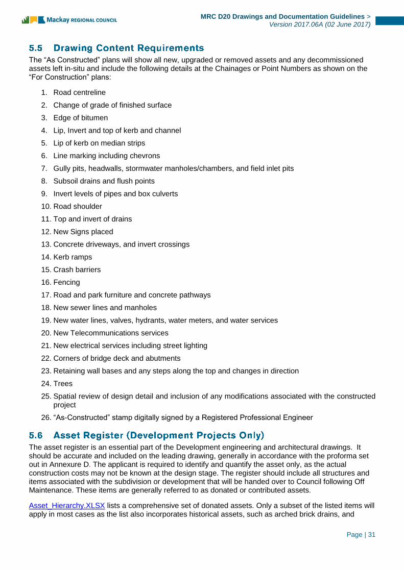
The “As Constructed” plans will show all new, upgraded or removed assets and any decommissioned assets left in-situ and include the following details at the Chainages or Point Numbers as shown on the “For Construction” plans:
1. Road centreline
2. Change of grade of finished surface
3. Edge of bitumen
4. Lip, Invert and top of kerb and channel
5. Lip of kerb on median strips
6. Line marking including chevrons
7. Gully pits, headwalls, stormwater manholes/chambers, and field inlet pits
8. Subsoil drains and flush points
9. Invert levels of pipes and box culverts
10. Road shoulder
11. Top and invert of drains
12. New Signs placed
13. Concrete driveways, and invert crossings
14. Kerb ramps
15. Crash barriers
16. Fencing
17. Road and park furniture and concrete pathways
18. New sewer lines and manholes
19. New water lines, valves, hydrants, water meters, and water services
20. New Telecommunications services
21. New electrical services including street lighting
22. Corners of bridge deck and abutments
23. Retaining wall bases and any steps along the top and changes in direction
24. Trees
25. Spatial review of design detail and inclusion of any modifications associated with the constructed project
26. “As-Constructed” stamp digitally signed by a Registered Professional Engineer
The asset register is an essential part of the Development engineering and architectural drawings. It should be accurate and included on the leading drawing, generally in accordance with the proforma set out in Annexure D. The applicant is required to identify and quantify the asset only, as the actual construction costs may not be known at the design stage. The register should include all structures and items associated with the subdivision or development that will be handed over to Council following Off Maintenance. These items are generally referred to as donated or contributed assets.
Asset_Hierarchy.XLSX lists a comprehensive set of donated assets. Only a subset of the listed items will apply in most cases as the list also incorporates historical assets, such as arched brick drains, and

Page | 32
MRC D20 Drawings and Documentation Guidelines >
Version 2017.06A (02 June 2017)
heritage construction materials, such as porphyry. The applicant should not assume that a listed item will imply automatic acceptance of a material or product.
The final asset register should reflect the actual construction and should be submitted with the “As-Constructed” drawings. For each item, the applicant should specify the asset type, quantity, unit rate, and estimated value. Council will use the unit rates solely for asset valuation and capitalisation.
Further to the above mentioned “As-constructed” information, a valid ‘Asset Design As Constructed’ (ADAC) XML file shall be submitted as a part of the “As-constructed” bundle. The file shall be valid to Council’s adopted ADAC Schema at the time that the works are being completed.
For further information regarding the creation of ADAC XML files, refer the following documents:
MRC Guidelines for “As-Constructed” and ADAC Survey Pick-up
MRC Guidelines for Creation and Submission of ADAC XML Files
MRC Guidelines for Creation of ADAC XML Files using 12d Model
The “As-Constructed” bundle of information shall be submitted in accordance with the following process flows to ensure plan and asset data acceptability and registration into the appropriate internal systems.

Page | 33
MRC D20 Drawings and Documentation Guidelines >
Version 2017.06A (02 June 2017)
Asset Services refers data to
Technical Services for storage of final “As-Constructed”
drawings
Electronic Data referred to Asset Services
Relevant program registers files against DA / OW / Project Files on ECM and uploads to BRUCE
Pre-lodgement Draft “As-Constructed” submission by Contractor or Developer
Relevant Program
Notification of data errors provided to generating program
No
Notification of acceptance provided
to generating Program
Contract / DA / OW Approval Issued by generating Program
Relevant program confirms engineering and drafting details
Relevant program requests design
modifications
Asset Services reviews asset data
acceptability
Drawing Index
Relevant program requests data modifications
Formal lodgement of “As-Constructed” Plans and Data
Transmittal Document and electronically signed / certified pdf / DWG plan submission
Start
Project End
No
Yes
Yes Yes
No

Page | 34
MRC D20 Drawings and Documentation Guidelines >
Version 2017.06A (02 June 2017)
Asset Capitalisation
Resp. Asset Officer
Modification of data errors
Resp. Designer
Compiled “As-Constructed” bundle uploaded to BRUCE and Drawing Index and issued to stakeholders.
Resp. Program Delegate
Determination made by generating program for “As-Con” Requirements
Resp. Program Coordinator
Asset Design As Constructed (ADAC) Survey completed (incl. pick-up completed during project
delivery), uploaded to BRUCE and issued to Stakeholders
Resp. Survey Officer
Notification of XML Acceptance
Add BRUCE library to ECM Project File
Resp. Program Delegate
Layers uploaded into GIS/MADI
Resp. GIS Officer
Asset Services reviews asset data
acceptability
“Red Pen” mark-ups of plans and estimate uploaded to BRUCE and
issued to Stakeholders
Resp. Admin Officer
Project Delivery
Project End
ADAC Survey issued to Designer to complete Valid
ADAC XML File
Resp. Program Coordinator
Design drawings issued to Designer to complete “As-
Constructed” plans
Resp. Program Coordinator
“As-Constructed” bundle compiled and issued to
stakeholders
Resp. Designer
ADAC Required
Plan Only Required

Page | 35
MRC D20 Drawings and Documentation Guidelines >
Version 2017.06A (02 June 2017)
The Designer shall submit a bound A4 Design Report with all plans lodged, excepting those plans for minor works. The Report shall include all the necessary design assumptions and calculations, correspondence and information to enable Council to expeditiously check the design submission or is required for historical records.
The Design Report shall be on company letterhead and shall contain the following minimum details:
a) The project details and the list of all plans (including sheet name and number) associated with the
project.
b) A copy of the development approval conditions, if applicable, or design brief, where Council is the
client, on which the design is based.
c) A copy of all separate approvals given by Council to variations from the minimum standard provided
for in the relevant Guideline.
d) Records of pre-submission discussions with Council including confirming correspondence.
e) Copies of letters of approval from adjoining property owners for any works or discharge on their
properties.
f) Evidence that arrangements have been entered into regarding provision and/or relocation of supply
with Ergon Energy and Telstra (including approved reticulation/service plans, if available).
g) A photographic report confirming that the Designer has visited the site to ensure all site constraints
have been considered and addressed
h) Pavement and wearing surface design assumptions and calculations.
i) Where available, records of geotechnical tests indicating design subgrade CBRs in cuts on which the
pavement design has been based. Copies of the geotechnical reports are to be included in the
design report.
j) Where additional subsoil drainage is required over and above Council’s minimum requirement, the
pavement design shall include design details for pavement drainage, prepared by a Geotechnical
Engineer.
k) Stormwater drainage calculations in spreadsheet format (in accordance with QUDM requirements)
together with details of pit types, capture charts used, bypass flows and flow widths at all pits.
l) Stormwater Drainage Catchment Plan detailing external catchments and internal sub catchments.
m) Design calculations for detention basins, dissipaters, scour protection and permanent water quality
control structures.
n) Geotechnical reports, where relevant, relating to slope and batter stability, in-situ materials etc.
o) Structural and Geotechnical certification of design of miscellaneous structures including retaining
walls, non-standard headwalls, drainage structures, reservoirs etc.
p) The street lighting design prepared by a suitably qualified and experienced professional engineer –
including evidence that both horizontal and vertical lighting requirements are complied with. This
shall also include any existing street lighting that requires removal during construction and measures
to ensure that existing illumination levels are not reduced during construction.
q) For staged development, plans showing the overall design concept for water, sewer, stormwater,
roadwork, cycleway and pathways, public open space, earthworks, erosion control and stormwater
management plans shall be submitted with Stage 1 and an updated copy provided with subsequent
stages.
Page | 36
MRC D20 Drawings and Documentation Guidelines >
Version 2017.06A (02 June 2017)
r) Any water reticulation networks analysis that are included shall be supplied in a format compatible
with Council’s network system where requested.
s) Engineer’s completed bill of quantities and estimate of cost.
t) All necessary details supporting any request by a developer for Council to financially contribute
toward the development.
u) Any other specific relevant details sought by Council
v) Erosion Sediment Control and site based stormwater management plans in accordance with
specification D7 as required.
w) Traffic Studies to a level of complexity required to justify road layouts, intersection treatments and
use of traffic calming devices.
x) Completed Design Certification Report by RPEQ – refer to Annexure A
Further, the Design Report shall include an appropriate response to information required in specific sections of the Design Guidelines, as detailed in Annexure B.
The design Engineer shall ensure that every new ‘section’ of the Design Report commences on a separate page, all pages are numbered and the Table of Contents clearly identifies all aspects within the report.
All documentation (including calculations and sketches) shall be either typed or neatly written or drawn in ink. The use of pencil is not acceptable.
For Council capital works projects, the designer shall prepare a design report in accordance with the project’s design brief and based on MRC FRM-23.004 in the “MRC Consultants Pack.” Access to the MRC Consultants Pack on MRC FileShare may be requested through the Manager of Council’s Technical Services Program.
In addition to requirements specified in MRC Guidelines for Creation and Submission of ADAC XML Files, certain asset classes/types have specific requirements (listed below):
Release / Sealing of subdivisional title plans will not occur until all required 'As Constructed' information in the necessary format is submitted.
Electronic copies of PDF and DWG drawings as specified above for the built structures including:
structural drawings
site layout
soil reports
footings
energy efficiency
building classification and compliance certificates
structural calculations
construction standards and specifications

Page | 37
MRC D20 Drawings and Documentation Guidelines >
Version 2017.06A (02 June 2017)
Electronic copies of PDF and DWG drawings as specified above for the built structure services provided in layers that clearly identify the principal contractor; contract number, revision number of the document. This includes:
electrical
mechanical
hydraulic
plumbing
gas
drainage
water reticulation and fire
Including asset/equipment register for the installed assets, especially:
the relevant warranty periods,
models
serial numbers
These manuals must be submitted electronically in both PDF and MS Word (editable) format.
Lists detailing painting, finishes, floor covering schedules (e.g. product colour code/descriptions).
These lists must be submitted electronically in both PDF and MS Word (editable) format.
Note: The above information should cover details of all assets that were incorporated in the relevant building approval processes.
For all water and sewerage treatment plants, pump stations and reservoirs the submitter must also provide:
Electronic copies of PDF and DWG drawings of all civil, mechanical/electrical works.
The layers must clearly identify:
the principal contractor
contract number
revision number of the document
Where works comprise pump stations, reservoirs, treatment plants stormwater quality devices etc., three (3) bound copies of Operations and Maintenance Manuals for all components of the works shall be provided.
A copy of each manual must also be submitted electronically in both PDF and MS Word (editable) format.

Page | 38
MRC D20 Drawings and Documentation Guidelines >
Version 2017.06A (02 June 2017)
Typical details of manuals for pump stations which are required to be included are as follows:
Contractor's name, address and telephone number
Client's Contract number, job name
Pump station general arrangement drawing showing pumps, motors, valves, pipe work,
switchboard and electrical installation
Manuals for pumps shall contain the following information:
Manufacturer
Type and model number
Serial number
Dimensioned general arrangement drawing of pump and motor
Sectional arrangement drawing with parts and list
Dimensioned sectional arrangements detailing:
o Maximum and minimum shaft / bearing clearance (radial)
o Maximum and minimum impeller / bowl clearance (radial)
o Maximum and minimum impeller / bowl clearance (axial)
o Impeller / bowl wear rings
o Motor / pump coupling - type, make and model number
o Mechanical seals where applicable
Manuals for motors shall contain the following information:
Manufacturer
Type and model number
Serial number
Dimensioned general arrangement drawing
Sectional arrangement for submersible motor power cabling where applicable
Gland sealing arrangement drawing for submersible motor power cabling where applicable
Cables where applicable
Terminal block arrangement drawing where applicable
Manuals for valves shall contain a dimensioned sectional arrangement drawing with parts and material list for all valves
Manuals shall contain the following test curves:
Pump witnessed test curves
Motor test curves
Motor torque / speed / efficiency characteristic curves
The operating and maintenance manual shall include:
Safe working procedures: For switching and isolating the supply and distribution system
Comprehensive description of operation, including flow charts detailing each operational activity
(e.g. manual pump operation, routine test procedures)
Maintenance procedures: Recommended maintenance periods and procedures
Tools: Particulars of maintenance equipment and tools provided, with instructions for their use

Page | 39
MRC D20 Drawings and Documentation Guidelines >
Version 2017.06A (02 June 2017)
Equipment: A technical description of the equipment supplied, with diagrams and illustrations
where appropriate
Dismantling: Where necessary, procedures for dismantling and reassembling equipment
Spare parts: A list of the spare parts provided
Troubleshooting instructions shall be included for pumps, motors, valves and SCA.
Step-by-step procedures for dismantling and reassembly of pumps, motors and valves using any
special tools shall be detailed together with step-by-step procedures for replacement of wearing
parts such as bearings, seals, wear rings, etc.
For all artificial wetland areas, the submitter must also provide:
Electronic copies of PDF and DWG design drawings of the artificial wetlands.
Maintenance plans and schedules for the artificial wetlands. These manuals must be submitted
electronically in both PDF and MS Word (editable) format.
For all SQID (including treatment plants and gross pollutant traps) the submitter must also provide:
Design specification details
Manufacturer and supplier contact details
Maintenance Manuals and procedures including:
o Clean-out procedures that address (at a minimum):
public safety
maintenance techniques
equipment requirements
environmental management considerations
occupational health and safety and disposal requirements
o Maintenance procedures and recommended frequencies for inspection, maintenance and
cleaning functions in both wet and dry seasons.

Page | 40
MRC D20 Drawings and Documentation Guidelines >
Version 2017.06A (02 June 2017)

Page | 41
MRC D20 Drawings and Documentation Guidelines >
Version 2017.06A (02 June 2017)
Project Title
DA/BA Number:
Consultant’s Drawing Number:
Name of Consultant:
Name and Address of Developer
I certify that the subject drawings represent a design:
☐ for which the attached design check lists provide a valid record;
OR
☐ which has been Audited through our approved QA system
I certify that this Design has been carried out in accordance with current standards of good industry practice and in accordance with MACKAY REGIONAL COUNCIL’s Design Guidelines, Local Laws, Planning Policies, Planning Scheme and specific instructions received except for departures cited in the attached design checklists for Council’s advice.
I certify that this Design will not significantly impact on the environment factors of the area as interpreted under the Sustainable Planning Act and Amendments and the Environmental Protection Act and Amendments.
I certify that this design meets requirements for obligations regarding safe design under the Workplace Health and Safety Act.
I certify that all structural elements of the Design have been designed by a competent qualified practicing Structural Engineer.
Design Engineer (Print):
Qualifications RPEQ Number
Signature Date

Page | 42
MRC D20 Drawings and Documentation Guidelines >
Version 2017.06A (02 June 2017)
Item Check Completed
by (Initials) Date
Not Applicable
(tick)
1. Initial Plot verified by site inspection for existing
drainage. ☐
2. Initial Plot verified by site inspection for existing
property descriptions, boundaries and
accesses.
☐
3. Initial Plot of contour verified as representative
of site terrain. ☐
4. Trees and significant environmental features
affected by development are clearly indicated
and annotated.
☐
5. Features significant to cultural heritage
considerations are clearly indicated and
annotated.
☐
6. Existing public and private property likely to be
affected by these Designs are clearly indicated
and annotated.
☐
7. Survey and benchmarks clearly indicated and
annotated. ☐
8. Existing and proposed utility services located
and clearly indicated ☐
Departures from Council’s standard requirements or special features to be noted
___________________________________________________________________________________
___________________________________________________________________________________
___________________________________________________________________________________
___________________________________________________________________________________
___________________________________________________________________________________
___________________________________________________________________________________
___________________________________________________________________________________
___________________________________________________________________________________
___________________________________________________________________________________
___________________________________________________________________________________

Page | 43
MRC D20 Drawings and Documentation Guidelines >
Version 2017.06A (02 June 2017)
Item Check Completed
by (Initials) Date
Not Applicable
(tick)
1. Alignment compatible with design speed. ☐
1.1. Any curves below minimum radius for
design speed?
1.2. Superelevation rates when compared with
horizontal curves in the design?
1.3. Superelevation transitions sufficient?
1.4. Tangent runout?
1.5. Does curvature cause sight distance
problems due to vegetation or other
obstacles?
2. Alignment is adequate in relation to clearance
of roadside hazards. ☐
3. Driver and Pedestrian sight distance is
adequate ☐
4. Conflict with existing services is minimised. ☐
5. Road widths and lanes meet Council’s and
design traffic requirements.
5.1. Is road widening required due to horizontal
curve radii?
☐
6. Alignment of bridges suits road alignment. ☐
7. Pedestrian, bicycle and parking requirements
are met. ☐
8. Provision for large vehicles such as buses,
garbage trucks and emergency vehicles is
adequate.
☐
9. Intersection layouts meet turning requirements
of design traffic including emergency vehicles. ☐
10. Pavement width tapers and mergers are
adequate. ☐
11. Pedestrians and prams are catered for. ☐
12. Conflict with existing Public Utility services has
been identified and resolved ☐
13. Horizontal road alignment has been provided in
accordance with any Conditions of
Development Consent
☐
14. Horizontal road alignment set out data is clearly
defined and tabulated ☐

Page | 44
MRC D20 Drawings and Documentation Guidelines >
Version 2017.06A (02 June 2017)
Departures from Council’s or State Authority’s standard requirements or special features to be noted
___________________________________________________________________________________
___________________________________________________________________________________
___________________________________________________________________________________
___________________________________________________________________________________
___________________________________________________________________________________
___________________________________________________________________________________
___________________________________________________________________________________
___________________________________________________________________________________
___________________________________________________________________________________
___________________________________________________________________________________

Page | 45
MRC D20 Drawings and Documentation Guidelines >
Version 2017.06A (02 June 2017)
Item Check Completed
by (Initials) Date
Not Applicable
(tick)
1. Grades meet maximum and minimum
requirements. ☐
2. Vertical clearances to bridges and services
meet standards. ☐
3. Vertical sight distance is adequate for drivers
and pedestrians. ☐
3.1. Are SSD and SISD achieved?
3.2. Any side roadways/ driveways affected by
sight distance?
3.3. Turning vehicles hidden by grades and
vertical curves?
4. Cover to drainage structures or services is
adequate. ☐
5. Vertical alignment is adequate for disposal of
surface drainage from properties and from
road.
☐
6. Grades are satisfactory for 1:100 year flood
levels. ☐
7. Vertical alignment is compatible with property
access. ☐
8. The gradient on an intersecting road is not
significantly greater than the cross slope of the
through pavement and no greater than 3% at
give way and stop signs.
☐
9. Sight distance is acceptable for all accesses to
roundabouts. ☐
10. Alignment co-ordination with horizontal
alignment is in accordance with the
AUSTROADS design guides as referenced in
the AUS-SPEC specifications.
☐
11. Conflict with existing Public Utility services has
been identified and resolved. ☐
12. Vertical road alignment set out data is clearly
identified on the longitudinal sections. ☐
Page | 46
MRC D20 Drawings and Documentation Guidelines >
Version 2017.06A (02 June 2017)
Departures from Council’s or State Authority’s standard requirements or special features to be noted
___________________________________________________________________________________
___________________________________________________________________________________
___________________________________________________________________________________
___________________________________________________________________________________
___________________________________________________________________________________
___________________________________________________________________________________
___________________________________________________________________________________
___________________________________________________________________________________
___________________________________________________________________________________
___________________________________________________________________________________

Page | 47
MRC D20 Drawings and Documentation Guidelines >
Version 2017.06A (02 June 2017)
Item Check Completed
by (Initials) Date
Not Applicable
(tick)
1. Typical Cross Sections have complete
dimensions. ☐
2. Typical Cross Sections have kerb and channel,
road safety barrier and surface drainage
indicated.
☐
3. Batter slopes are indicated and batter
treatment is indicated where appropriate ☐
4. Property boundaries, service locations and
location of known existing underground
services and pathway treatments are indicated.
☐
5. Sufficient Cross Sections are shown to define
all variations and width transitions. ☐
6. Cross sections are of sufficient width to fully
assess impact of road level on adjoining
property.
☐
7. Stability of embankment slopes, batters and
retaining walls has been verified as
satisfactory.
☐
8. Cross section reference level conforms with
vertical road alignments. ☐
Departures from Council’s or State Authority’s standard requirements or special features to be noted
___________________________________________________________________________________
___________________________________________________________________________________
___________________________________________________________________________________
___________________________________________________________________________________
___________________________________________________________________________________
___________________________________________________________________________________
___________________________________________________________________________________
___________________________________________________________________________________
___________________________________________________________________________________
___________________________________________________________________________________

Page | 48
MRC D20 Drawings and Documentation Guidelines >
Version 2017.06A (02 June 2017)
Item Check Completed
by (Initials) Date
Not Applicable
(tick)
1. Drawings indicate existing surface drainage. ☐
2. Hydrological data is the most current available. ☐
3. Hydrologic and Hydraulic design calculations
are complete and fully recorded and available
for audit.
☐
4. Underground drainage and structures do not
conflict with services ☐
5. The designed drainage lines are compatible
with existing incoming lines and outgoing lines. ☐
6. The length of line, type of pipe, size, class and
bedding requirements are indicated for each
drainage line as well on the schedule of
drainage elements.
☐
7. Height of fill over drainage lines is within
allowable limits. ☐
8. Drainage is provided for local depressions e.g.
median areas or areas adjacent to fills. ☐
9. The effect of headwater and back-up water on
private property has been assessed. ☐
10. Subsurface drainage has been provided when
required and clearly located by line and level,
with details provided.
☐
11. The need for batter drains has been
considered for fills and cuttings. ☐
12. The height and energy level of downstream
drainage has been considered. ☐
13. Drainage structures and flow paths are located
to ensure safe vehicular and pedestrian transit. ☐
14. Drainage structure number, set out, type and
pipe details indicated on the drainage plans
and schedule of drainage elements.
☐
15. Emergency flow paths are located to minimise
impact on private property. ☐
16. Road drainage has been provided in
accordance with any Conditions of
Development Consent
☐
17. Interallotment drains have been designed in
accordance with Council’s Specification and/or
Australian Rainfall and Runoff (Edition 1987) or
The Queensland Urban Drainage Manual.
☐

Page | 49
MRC D20 Drawings and Documentation Guidelines >
Version 2017.06A (02 June 2017)
Item Check Completed
by (Initials) Date
Not Applicable
(tick)
18. Appropriate land stabilisation and Velocity
controls have been implemented to pipe
systems, open channels and embankments.
☐
19. For allotments affected by flood controls, the
floor height controls are to be compatible with
road and drainage levels.
☐
Departures from Council’s or State Authority’s standard requirements or special features to be noted
___________________________________________________________________________________
___________________________________________________________________________________
___________________________________________________________________________________
___________________________________________________________________________________
___________________________________________________________________________________
___________________________________________________________________________________
___________________________________________________________________________________
___________________________________________________________________________________
___________________________________________________________________________________
___________________________________________________________________________________

Page | 50
MRC D20 Drawings and Documentation Guidelines >
Version 2017.06A (02 June 2017)
Item Check Completed
by (Initials) Date
Not Applicable
(tick)
1. Sign types, sizes, locations and support
structure details are shown on the drawings in
accordance with the QMUTCD.
☐
2. Pavement line marking and pavement marking
type and set out is indicated on the drawings to
meet the requirements of the QMUTCD.
☐
3. Signs and line marking have been designed in
accordance with any Conditions of
Development Consent.
☐
4. It is physically possible to place sign where
indicated? Is there sufficient horizontal
clearance?
☐
5. Any existing signage that needs to be
replaced? Any conflicting existing signage? ☐
Departures from Council’s or State Authority’s standard requirements or special features to be noted
___________________________________________________________________________________
___________________________________________________________________________________
___________________________________________________________________________________
___________________________________________________________________________________
___________________________________________________________________________________
___________________________________________________________________________________
___________________________________________________________________________________
___________________________________________________________________________________
___________________________________________________________________________________
___________________________________________________________________________________
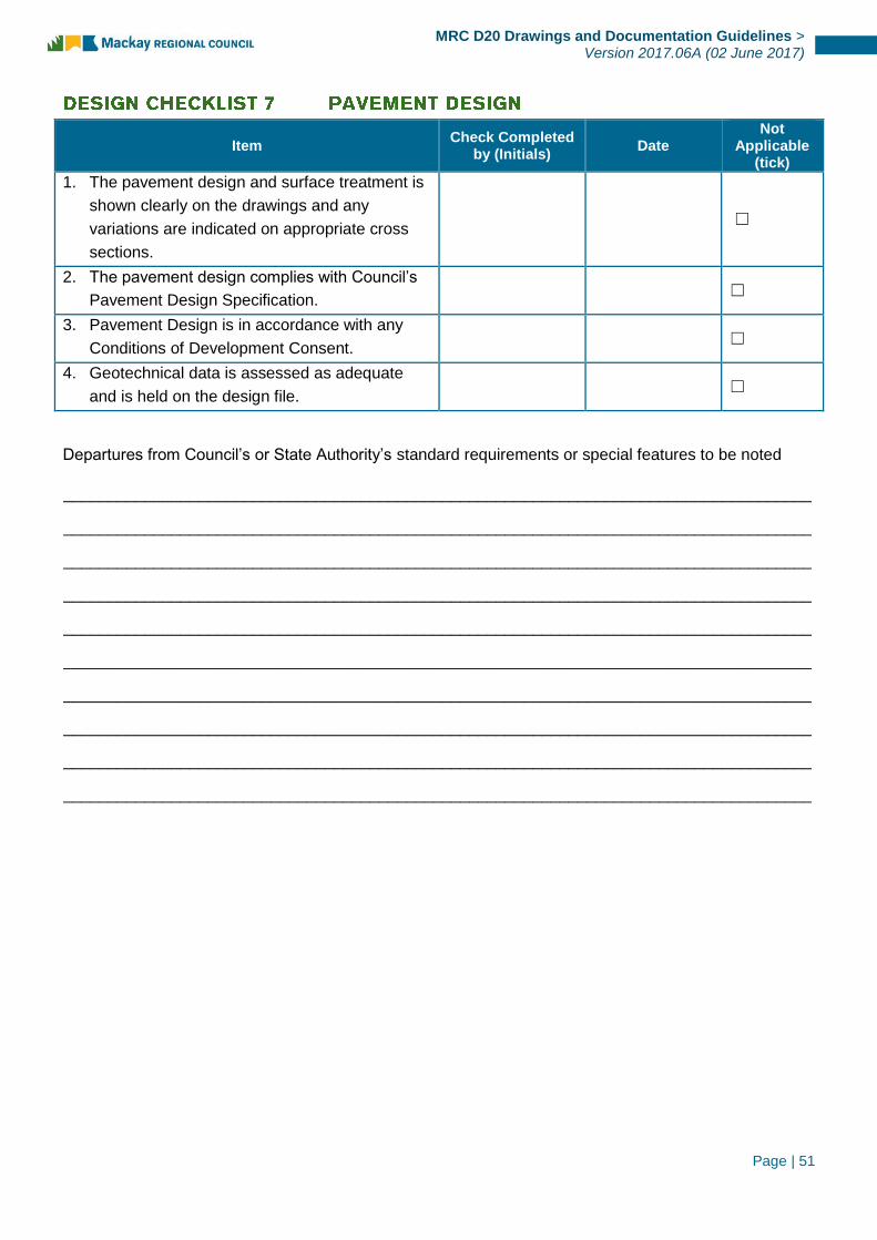
Page | 51
MRC D20 Drawings and Documentation Guidelines >
Version 2017.06A (02 June 2017)
Item Check Completed
by (Initials) Date
Not Applicable
(tick)
1. The pavement design and surface treatment is
shown clearly on the drawings and any
variations are indicated on appropriate cross
sections.
☐
2. The pavement design complies with Council’s
Pavement Design Specification. ☐
3. Pavement Design is in accordance with any
Conditions of Development Consent. ☐
4. Geotechnical data is assessed as adequate
and is held on the design file. ☐
Departures from Council’s or State Authority’s standard requirements or special features to be noted
___________________________________________________________________________________
___________________________________________________________________________________
___________________________________________________________________________________
___________________________________________________________________________________
___________________________________________________________________________________
___________________________________________________________________________________
___________________________________________________________________________________
___________________________________________________________________________________
___________________________________________________________________________________
___________________________________________________________________________________
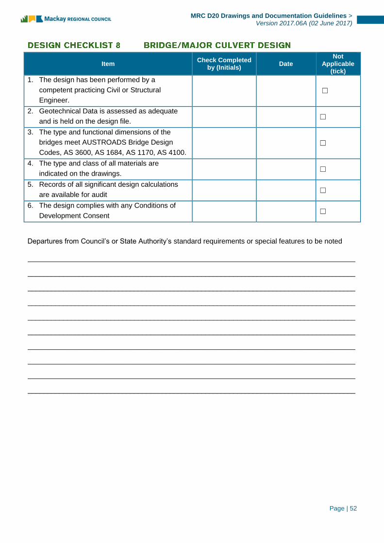
Page | 52
MRC D20 Drawings and Documentation Guidelines >
Version 2017.06A (02 June 2017)
Item Check Completed
by (Initials) Date
Not Applicable
(tick)
1. The design has been performed by a
competent practicing Civil or Structural
Engineer.
☐
2. Geotechnical Data is assessed as adequate
and is held on the design file. ☐
3. The type and functional dimensions of the
bridges meet AUSTROADS Bridge Design
Codes, AS 3600, AS 1684, AS 1170, AS 4100.
☐
4. The type and class of all materials are
indicated on the drawings. ☐
5. Records of all significant design calculations
are available for audit ☐
6. The design complies with any Conditions of
Development Consent ☐
Departures from Council’s or State Authority’s standard requirements or special features to be noted
___________________________________________________________________________________
___________________________________________________________________________________
___________________________________________________________________________________
___________________________________________________________________________________
___________________________________________________________________________________
___________________________________________________________________________________
___________________________________________________________________________________
___________________________________________________________________________________
___________________________________________________________________________________
___________________________________________________________________________________

Page | 53
MRC D20 Drawings and Documentation Guidelines >
Version 2017.06A (02 June 2017)
Item Check Completed
by (Initials) Date
Not Applicable
(tick)
1. Both short term and long term erosion control
plans have been prepared using the guidelines
within Council’s Design Specification D7
☐
2. Erosion and Sedimentation Control has been
designed in accordance with any Conditions of
Development Consent.
☐
Departures from Council’s or State Authority’s standard requirements or special features to be noted
___________________________________________________________________________________
___________________________________________________________________________________
___________________________________________________________________________________
___________________________________________________________________________________
___________________________________________________________________________________
___________________________________________________________________________________
___________________________________________________________________________________
___________________________________________________________________________________
___________________________________________________________________________________
___________________________________________________________________________________

Page | 54
MRC D20 Drawings and Documentation Guidelines >
Version 2017.06A (02 June 2017)
Item Check Completed
by (Initials) Date
Not Applicable
(tick)
1. Is the project constructible using the Traffic
Control Plan? Does the traffic control affect the
design such as material requirements for
roadways used for public use during the
construction? Traffic restrictions?
☐
2. Is there enough work area and staging areas
for the contractor to undertake construction
operations? Does the construction traffic
control allow for Contractor access?
☐
3. What is the design speed of construction traffic
control? ☐
4. Is the work site safe for both traffic and
workers? ☐
5. Is construction signage in accordance with Part
3 of QMUTCD? ☐
6. Do the sign messages convey the intended
actions that are required to be taken? ☐
7. Do the signs have the proper legends, sizes,
colour combinations and reflectivity? ☐
8. Are there existing signs within the construction
zone that may conflict with the traffic Control
Plan? Do any of the existing signs obscure the
view of advance warning signs?
☐
9. If staged construction is used, is the signage
from stage to stage consistent? ☐
10. Is a detour provided? Are all access points
properly signed? ☐
11. Is it physically possible to place the signage
where indicated? Is there sufficient horizontal
clearance?
☐
12. Is there a need for any pedestrian or bicycle
signage? ☐
13. Are channelisation devices required and are
they appropriate for the operation? ☐
14. Are channelisation tapers located correctly?
Are they the correct length? Are devices
spaced correctly in the taper? Spaced
correctly in the work area?
☐
15. Devices meet QMUTCD requirements for size,
type, colour, reflectivity? ☐
16. Are the devices properly ballasted? ☐

Page | 55
MRC D20 Drawings and Documentation Guidelines >
Version 2017.06A (02 June 2017)
Item Check Completed
by (Initials) Date
Not Applicable
(tick)
17. Do existing pavement markings conflict with the
proposed temporary markings? ☐
18. Is marking consistent, especially during staged
construction? ☐
19. Are warning lights used correctly? Adequate
sight distance for arrow boards? ☐
20. Are construction areas properly shielded? Are
temporary barriers required? Is it physically
possible to place barriers as shown in the
TCP?
☐
21. Contact numbers in case of emergencies
available? If special construction events exist,
are contact procedures in place to notify/
receive approval from authorities?
☐
22. Are work time restrictions in place? ☐
23. Is there a possibility of pedestrians and cyclists
in the project area? Have they been
considered?
☐
24. Does the traffic control or construction
operations cause drainage problems? ☐
25. For projects with staged construction are there
provisions to accomplish stage change overs? ☐
Departures from Council’s or State Authority’s standard requirements or special features to be noted
___________________________________________________________________________________
___________________________________________________________________________________
___________________________________________________________________________________
___________________________________________________________________________________
___________________________________________________________________________________
___________________________________________________________________________________
___________________________________________________________________________________
___________________________________________________________________________________
___________________________________________________________________________________
___________________________________________________________________________________

Page | 56
MRC D20 Drawings and Documentation Guidelines >
Version 2017.06A (02 June 2017)

Page | 57
MRC D20 Drawings and Documentation Guidelines >
Version 2017.06A (02 June 2017)
Specific details shall be submitted to Council in the Design Report as required in the following sections of various Design Guidelines:
Design Guideline Section Brief Description
D1 – Geometric Road Design
1.2 QT approval for bus routes and stops
1.8 Intersection spacing – functional performance maintained
1.9 Design Speed
1.22 Street lighting design – both horizontal and vertical
D2 – Pavement Design
1.5.1 Design Traffic
1.5.2 Sub-grade evaluation
1.5.3 Environment
1.5.4 Pavement and Surface materials
1.5.5 Construction and Maintenance Considerations
1.6 Pavement Thickness design
1.7 Surface design
D3 – Structures – Bridge design
1.5 Backwater effect
1.5 TMR pre-registration evidence
1.5 Public Utility discussions
D4 – Subsurface Drainage design 1.5 Geotechnical Report – if subsoil drains to be eliminated
D5 - Stormwater Drainage Design
1.5.1 Design Rainfall Data – Hydrology
1.5.2 Catchment Area
1.5.3 Rational Method calculations
1.5.4 Rational Method – computer analysis
1.6.1 Hydraulic Grade Line
1.9.1 Details required when design outlet is below HAT
1.9.5 Proposed easement details
1.9.5 Deed of Agreement – to construct works on adjacent property
1.9.5 Agreement – to increase flood level on upstream properties
1.10.2 Hydrological Summary Sheet
1.11.1 Overland Flow – weir calculations

Page | 58
MRC D20 Drawings and Documentation Guidelines >
Version 2017.06A (02 June 2017)

Page | 59
MRC D20 Drawings and Documentation Guidelines >
Version 2017.06A (02 June 2017)
We hereby certify that the locations, surface and invert levels of all works and infrastructure presented on the drawings noted below and in the digital data have been surveyed and meet the accuracy standards as defined by Mackay Regional Council.
SBQ Registrant
Surveying Associate/Surveying Graduate/Surveyor
SBQ Number
Director:
Date:
Drawings and Documents pertaining to the above:
Page | 60
MRC D20 Drawings and Documentation Guidelines >
Version 2017.06A (02 June 2017)

Page | 61
MRC D20 Drawings and Documentation Guidelines >
Version 2017.06A (02 June 2017)
Project:
Stage No:
Supervising Engineer:
Project Principal
Date
Asset Unit Quantity Rates Totals
Kerb and Channel m length
Median Kerb m length
Two coat seal m2 area
AC Seal m2 area
Subgrade Replacement Road Name
m2/m area/depth
Base Course Road Name
m2/m area/depth
Top Course Road Name
m2/m area/depth
Conc. Footpath m length
Stormwater Drainage Pipes diameter length
Entry Pits Type Road Gully Manholes Property Pits
number
Concrete Drains width (m) length (m)
Sewerage Reticulation Pipes diameter/depth
length
Manholes diameter number
Pump Stations type/size number
Rising Sewer Mains diameter length
Water Reticulation Pipes diameter length
Hydrants number
Valves type/size number
Pump Stations type/size number
Reservoirs volume number
Misc-Roads item
Misc-Stormwater item
Misc-Sewer item
Misc-Water item
Turf/Grass (Area within Road Reserve)
area(m2) number
Garden (Area within road reserve) area(m2) number
Turf/Grass (Area within Park/Council reserve)
area(m2) number
Garden (Area within Park/Council reserve)
area(m2) number
Tree (Size within road reserve) size(L) number
Tree (Size within Park/Council reserve)
size(L) number