Version 1 - cambridgesound.com · 2 Qt PRO™ Control Unit — OUTSIDE Qt PROTM Control Unit —...
16
www.csmqt.com/qtprosupport Qt 900 ™ / Qt 1500 ™ INSTALLATION AND OPERATIONS GUIDE Version 1.4 www.csmqt.com/qtprosupport Sound Masking - Paging - Music IMPORTANT NOTE FOR USERS AND INSTALLERS There are two ways to operate this Qt PRO ™ system: • Via front panel of control unit (see page 5); or • Via networked software - Recommended (see page 6) Installation of Control Unit 2 – 3 Installation of Emitters 3 – 4 Front Panel Control 5 – 6 Networked Software Control 6 – 8 Adjusting Sound Levels 8 – 10 Volume Ramping 10 – 11 Walkthrough Procedure 11 Custom Cabling Guidelines 12 Errors 13 – 14 Specifications 14 – 15 Warranty 15 Settings Record 16 Purchase date: Install date: MAC Address:
Transcript of Version 1 - cambridgesound.com · 2 Qt PRO™ Control Unit — OUTSIDE Qt PROTM Control Unit —...
www.csmqt.com/qtprosupport
Qt 900™ / Qt 1500™
INSTALLATION AND OPERATIONS GUIDE
Version 1.4 www.csmqt.com/qtprosupport
Sound Masking - Paging - Music
IMPORTANT NOTE FOR USERS AND INSTALLERS
There are two ways to operate this Qt PRO™ system:
• Via front panel of control unit (see page 5); or
• Via networked software - Recommended (see page 6)
Installation of Control Unit 2 – 3
Installation of Emitters 3 – 4
Front Panel Control 5 – 6
Networked Software Control 6 – 8
Adjusting Sound Levels 8 – 10
Volume Ramping 10 – 11
Walkthrough Procedure 11
Custom Cabling Guidelines 12
Errors 13 – 14
Specifications 14 – 15
Warranty 15
Settings Record 16
Purchase date: Install date:
MAC Address:
2
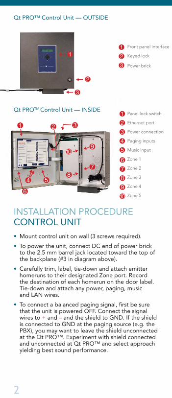
Qt PRO™ Control Unit — OUTSIDE
Qt PROTM Control Unit — INSIDE
INSTALLATION PROCEDURE CONTROL UNIT• Mount control unit on wall (3 screws required).
• To power the unit, connect DC end of power brick to the 2.5 mm barrel jack located toward the top of the backplane (#3 in diagram above).
• Carefully trim, label, tie-down and attach emitter homeruns to their designated Zone port. Record the destination of each homerun on the door label. Tie-down and attach any power, paging, music and LAN wires.
• To connect a balanced paging signal, first be sure that the unit is powered OFF. Connect the signal wires to + and – and the shield to GND. If the shield is connected to GND at the paging source (e.g. the PBX), you may want to leave the shield unconnected at the Qt PRO™. Experiment with shield connected and unconnected at Qt PRO™ and select approach yielding best sound performance.
Panel lock switch
Ethernet port
Power connection
Paging inputs
Music input
Zone 3
Zone 5
Zone 4
Zone 2
Zone 11
2
2
3
3
4
4 55 10
10
9
9
8
8
7
7
6
6
1
1
2
2
3
3
1
Panel lock switch
Front panel interface
Ethernet port
Keyed lock
Power connection
Power brick
Paging inputs
Music input
Zone 1
Zone 2
Zone 3
Zone 4
Zone 5
1
2
2
3
3
1
Panel lock switch
Ethernet port
Power connection
Paging inputs
Music input
Zone 3
Zone 5
Zone 4
Zone 2
Zone 11
2
2
3
3
4
4 55 10
10
9
9
8
8
7
7
6
6
1
Panel lock switch
Ethernet port
Power connection
Paging inputs
Music input
Zone 3
Zone 5
Zone 4
Zone 2
Zone 11
2
2
3
3
4
4 55 10
10
9
9
8
8
7
7
6
6
1
www.csmqt.com/qtprosupport 3
• To connect an unbalanced (single-ended) paging signal, connect the signal wire to + and connect the ground wire to both – and GND, using a shunt wire between – and GND.
IMPORTANT: When installing cables for Zone 1 (con-nectors on the door), leave sufficient length so that the front door can be fully opened with cables securely tied to the door. Measure with the door fully open.
• If a network attachment is made, confirm that a connection is made. To do this, advance to the IP Address screen on the front panel. If a network connection has been made, the assigned IP address will be displayed, usually within two (2) minutes of powering the unit. If the IP Address continues to read zero, contact the local network administrator.
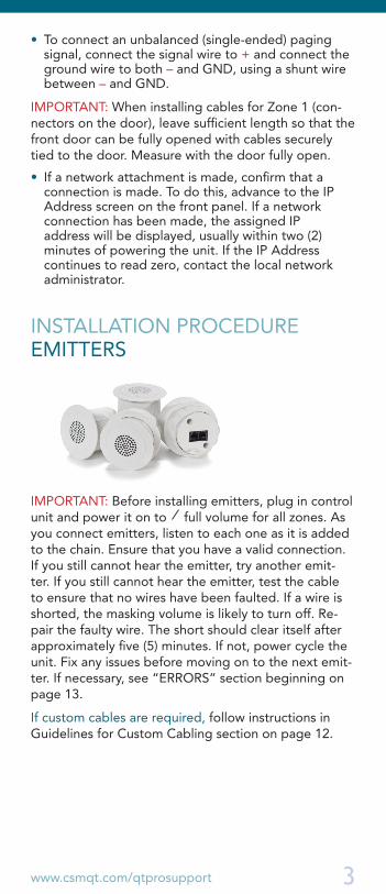
INSTALLATION PROCEDURE EMITTERS
IMPORTANT: Before installing emitters, plug in control unit and power it on to full volume for all zones. As you connect emitters, listen to each one as it is added to the chain. Ensure that you have a valid connection. If you still cannot hear the emitter, try another emit-ter. If you still cannot hear the emitter, test the cable to ensure that no wires have been faulted. If a wire is shorted, the masking volume is likely to turn off. Re-pair the faulty wire. The short should clear itself after approximately five (5) minutes. If not, power cycle the unit. Fix any issues before moving on to the next emit-ter. If necessary, see “ERRORS” section beginning on page 13.
If custom cables are required, follow instructions in Guidelines for Custom Cabling section on page 12.
Front panel interface
#
To Install Emitters:• Refer to emitter layout drawings provided by dealer.
• Remove and gather all ceiling tiles that are to re-ceive an emitter.
• Using the supplied hole saw, cut holes (front to back) in each ceiling tile that will receive an emitter.
• Cut in the center of a 2' x 2' tile. In other tile sizes, cut as appropriate to achieve required spacing.
• Cut all tiles at once to save time.
• Gently push the emitter through the hole from the front of the tile. Secure the emitter by twisting the lock-ring into place on the back of the tile.
• If there is no suspended ceiling, alternate emitter housings should be provided. Contact your dealer with questions.
• Place 16-foot patch cables between the openings in the ceiling grid where the tiles are to be re-installed.
• Provide strain relief or cable hangers as required by local code.
• Install ceiling tiles outward from the control module, connecting the output cable from one emitter to the input jack of the next emitter.
• IT IS ESSENTIAL TO CONNECT THE OUTPUT CABLE TO THE INPUT JACK OF THE NEXT EMITTER. (This is an operational, not a safety, issue.)
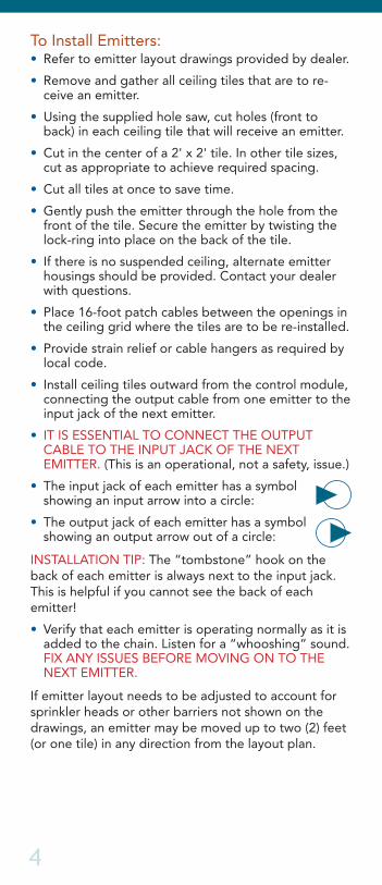
• The input jack of each emitter has a symbol showing an input arrow into a circle:
• The output jack of each emitter has a symbol showing an output arrow out of a circle:
INSTALLATION TIP: The “tombstone” hook on the back of each emitter is always next to the input jack. This is helpful if you cannot see the back of each emitter!
• Verify that each emitter is operating normally as it is added to the chain. Listen for a “whooshing” sound. FIX ANY ISSUES BEFORE MOVING ON TO THE NEXT EMITTER.
If emitter layout needs to be adjusted to account for sprinkler heads or other barriers not shown on the drawings, an emitter may be moved up to two (2) feet (or one tile) in any direction from the layout plan.
4
#www.csmqt.com/qtprosupport
ACCESSING, SETTING AND OPERATING THE SYSTEMEach Qt PRO™ unit ships ready to be used as either a standalone system or a network-connected system.
STANDALONE MODE (FRONT PANEL CONTROL)Qt PRO™ can be controlled from its front panel.(Some features are only available in Networked mode.)
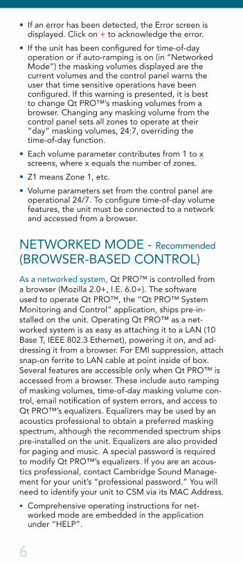
To control Qt PRO™ from the front panel:• Set the Panel Lock switch to the UNLOCKED
position. (Refer to diagram on page 2.) If the LCD display is blank or difficult to read adjust LCD contrast (+ or –).
• Use NEXT and PREVIOUS to scroll between screens. When a parameter displays, you can modify its value by pressing + or –. When you are satisfied, press NEXT to continue to the next param-eter or PREVIOUS to return to the previous param-eter. Qt PRO™ returns automatically to the Version, Status screen after five minutes of no activity.
Front Panel Control MapVersion, Status +/- to adjust contrast [Error Register] +/- to acknowledge error MAC Address IP Address Hostname Username Password [Warning: Time of Day Ops] Masking Z(1:x) Volume +/- (0:30) Paging A Sensitivity +/- (0:10) Paging A Z(1:x) Volume +/- (0:15) Paging B Sensitivity +/- (0:10) Paging B Z(1:x) Volume +/- (0:15) Music Sensitivity +/- (0:10) Music Z(1:x) Volume +/- (0:15)
Notes• [ ]: Screen only appears when applicable.
PREV NEXT
+
-
5
6
• If an error has been detected, the Error screen is displayed. Click on + to acknowledge the error.
• If the unit has been configured for time-of-day operation or if auto-ramping is on (in “Networked Mode”) the masking volumes displayed are the current volumes and the control panel warns the user that time sensitive operations have been configured. If this warning is presented, it is best to change Qt PRO™’s masking volumes from a browser. Changing any masking volume from the control panel sets all zones to operate at their “day” masking volumes, 24:7, overriding the time-of-day function.
• Each volume parameter contributes from 1 to x screens, where x equals the number of zones.
• Z1 means Zone 1, etc.
• Volume parameters set from the control panel are operational 24/7. To configure time-of-day volume features, the unit must be connected to a network and accessed from a browser.
NETWORKED MODE - Recommended (BROWSER-BASED CONTROL)As a networked system, Qt PRO™ is controlled from a browser (Mozilla 2.0+, I.E. 6.0+). The software used to operate Qt PRO™, the “Qt PRO™ System Monitoring and Control” application, ships pre-in-stalled on the unit. Operating Qt PRO™ as a net-worked system is as easy as attaching it to a LAN (10 Base T, IEEE 802.3 Ethernet), powering it on, and ad-dressing it from a browser. For EMI suppression, attach snap-on ferrite to LAN cable at point inside of box. Several features are accessible only when Qt PRO™ is accessed from a browser. These include auto ramping of masking volumes, time-of-day masking volume con-trol, email notification of system errors, and access to Qt PRO™’s equalizers. Equalizers may be used by an acoustics professional to obtain a preferred masking spectrum, although the recommended spectrum ships pre-installed on the unit. Equalizers are also provided for paging and music. A special password is required to modify Qt PRO™’s equalizers. If you are an acous-tics professional, contact Cambridge Sound Manage-ment for your unit’s “professional password.” You will need to identify your unit to CSM via its MAC Address.
• Comprehensive operating instructions for net-worked mode are embedded in the application under “HELP”.
www.csmqt.com/qtprosupport 7
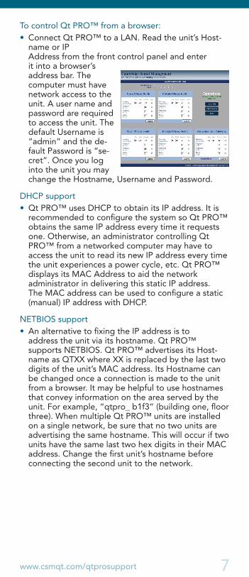
To control Qt PRO™ from a browser:• Connect Qt PRO™ to a LAN. Read the unit’s Host-
name or IP Address from the front control panel and enter it into a browser’s address bar. The computer must have network access to the unit. A user name and password are required to access the unit. The default Username is “admin” and the de-fault Password is “se-cret”. Once you log into the unit you may change the Hostname, Username and Password.
DHCP support• Qt PRO™ uses DHCP to obtain its IP address. It is
recommended to configure the system so Qt PRO™ obtains the same IP address every time it requests one. Otherwise, an administrator controlling Qt PRO™ from a networked computer may have to access the unit to read its new IP address every time the unit experiences a power cycle, etc. Qt PRO™ displays its MAC Address to aid the network administrator in delivering this static IP address. The MAC address can be used to configure a static (manual) IP address with DHCP.
NETBIOS support• An alternative to fixing the IP address is to
address the unit via its hostname. Qt PRO™ supports NETBIOS. Qt PRO™ advertises its Host-name as QTXX where XX is replaced by the last two digits of the unit’s MAC address. Its Hostname can be changed once a connection is made to the unit from a browser. It may be helpful to use hostnames that convey information on the area served by the unit. For example, “qtpro_ b1f3” (building one, floor three). When multiple Qt PRO™ units are installed on a single network, be sure that no two units are advertising the same hostname. This will occur if two units have the same last two hex digits in their MAC address. Change the first unit’s hostname before connecting the second unit to the network.
8
Other Required Connections
• The unit requires access to a SMTP server for send-ing error notification emails. Do not allow email replies to the unit.
• The unit requires access to an SNTP server for obtaining an NTP time stamp. The unit sends its SNTP request to “pool.ntp.org”.
• If software updates are to be performed, the computer running the Qt PRO™ System Monitoring and Control application requires TFTP access to the unit.
Managing multiple control modules
• Browser “bookmarks” are a convenient tool for managing multiple Qt PRO™ control modules. Consider using a bookmark add-on that stores your bookmarks on a web server for access to them from any computer.
• Create a “Sound Masking” folder under Bookmarks. Add a bookmark to each unit. Give them location-based names. When you need to access a Qt PRO™ unit, open Bookmarks > Sound Masking and select the target unit’s bookmark.
• Qt PRO™’s system overview page (big.htm) is designed to be legible as the display page of a thumbnail bookmark. By bookmarking each unit’s main page using thumbnail bookmarks, the status of the entire Qt PRO™ installation can be viewed from a single screen.
ADJUSTING SOUND LEVELSSystem volumes may be adjusted using either the front panel controls or the software interface.
Masking Volume AdjustmentImportant information about sound masking: It is es-sential that the unit’s masking volumes be set correctly, for each zone, to obtain the full effectiveness of the system. If volumes are set too low, speech privacy will be reduced and workplace distractions will be more apparent. If volumes are set too high, the masking sound itself may become a source of distraction. Acoustic privacy increases as sound masking volume increases, so the ideal level is one that is high enough to be effective but not so high as to be distracting.
www.csmqt.com/qtprosupport 9
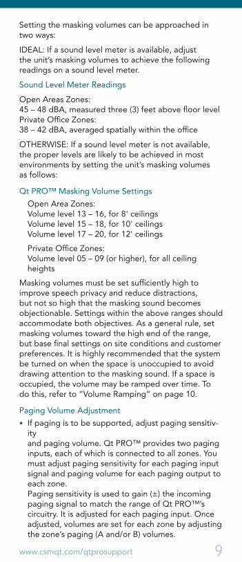
Setting the masking volumes can be approached in two ways:
IDEAL: If a sound level meter is available, adjust the unit’s masking volumes to achieve the following readings on a sound level meter.
Sound Level Meter Readings
Open Areas Zones: 45 – 48 dBA, measured three (3) feet above floor level Private Office Zones: 38 – 42 dBA, averaged spatially within the office
OTHERWISE: If a sound level meter is not available, the proper levels are likely to be achieved in most environments by setting the unit’s masking volumes as follows:
Qt PRO™ Masking Volume Settings
Open Area Zones: Volume level 13 – 16, for 8' ceilings Volume level 15 – 18, for 10' ceilings Volume level 17 – 20, for 12' ceilings
Private Office Zones: Volume level 05 – 09 (or higher), for all ceiling heights
Masking volumes must be set sufficiently high to improve speech privacy and reduce distractions, but not so high that the masking sound becomes objectionable. Settings within the above ranges should accommodate both objectives. As a general rule, set masking volumes toward the high end of the range, but base final settings on site conditions and customer preferences. It is highly recommended that the system be turned on when the space is unoccupied to avoid drawing attention to the masking sound. If a space is occupied, the volume may be ramped over time. To do this, refer to “Volume Ramping” on page 10.
Paging Volume Adjustment
• If paging is to be supported, adjust paging sensitiv-ity and paging volume. Qt PRO™ provides two paging inputs, each of which is connected to all zones. You must adjust paging sensitivity for each paging input signal and paging volume for each paging output to each zone. Paging sensitivity is used to gain (±) the incoming paging signal to match the range of Qt PRO™’s circuitry. It is adjusted for each paging input. Once adjusted, volumes are set for each zone by adjusting the zone’s paging (A and/or B) volumes.
1 0
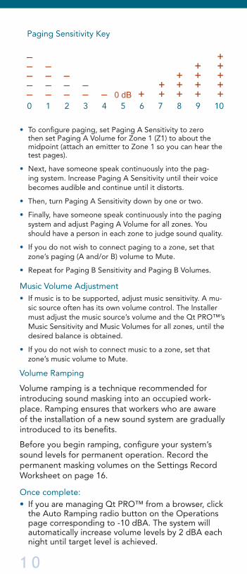
• To configure paging, set Paging A Sensitivity to zero then set Paging A Volume for Zone 1 (Z1) to about the midpoint (attach an emitter to Zone 1 so you can hear the test pages).
• Next, have someone speak continuously into the pag-ing system. Increase Paging A Sensitivity until their voice becomes audible and continue until it distorts.
• Then, turn Paging A Sensitivity down by one or two.
• Finally, have someone speak continuously into the paging system and adjust Paging A Volume for all zones. You should have a person in each zone to judge sound quality.
• If you do not wish to connect paging to a zone, set that zone’s paging (A and/or B) volume to Mute.
• Repeat for Paging B Sensitivity and Paging B Volumes.
Music Volume Adjustment • If music is to be supported, adjust music sensitivity. A mu-
sic source often has its own volume control. The Installer must adjust the music source’s volume and the Qt PRO™’s Music Sensitivity and Music Volumes for all zones, until the desired balance is obtained.
• If you do not wish to connect music to a zone, set that zone’s music volume to Mute.
Volume Ramping
Volume ramping is a technique recommended for introducing sound masking into an occupied work-place. Ramping ensures that workers who are aware of the installation of a new sound system are gradually introduced to its benefits.
Before you begin ramping, configure your system’s sound levels for permanent operation. Record the permanent masking volumes on the Settings Record Worksheet on page 16.
Once complete: • If you are managing Qt PRO™ from a browser, click
the Auto Ramping radio button on the Operations page corresponding to -10 dBA. The system will automatically increase volume levels by 2 dBA each night until target level is achieved.
Paging Sensitivity Key
0 1 2 3 4 5 6 7 8 9 10
– – – – –
–
– – –
+
+ + + +
– – – – 0 dB
+ + +
– –
+ +
+ + + + +
www.csmqt.com/qtprosupport 11
If you are using a browser, subsequent adjustments are automatic and you may disregard the information below.
• If you are managing Qt PRO™ from the front control panel, set the unit’s masking volumes to be 6-10 lev-els lower on Day 1. Using the control panel, make a +2 level adjustment before each workday begins, until you reach the permanent masking volumes.
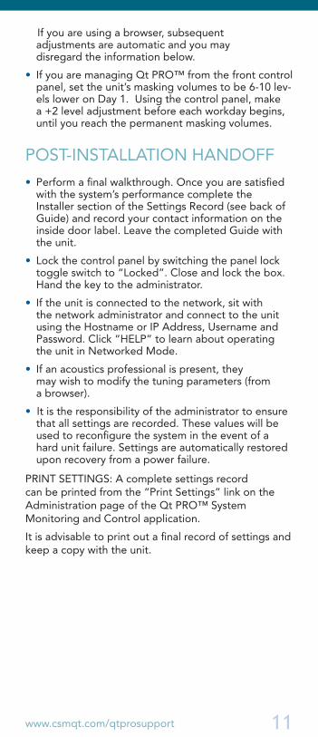
POST-INSTALLATION HANDOFF
• Perform a final walkthrough. Once you are satisfied with the system’s performance complete the Installer section of the Settings Record (see back of Guide) and record your contact information on the inside door label. Leave the completed Guide with the unit.
• Lock the control panel by switching the panel lock toggle switch to “Locked”. Close and lock the box. Hand the key to the administrator.
• If the unit is connected to the network, sit with the network administrator and connect to the unit using the Hostname or IP Address, Username and Password. Click “HELP” to learn about operating the unit in Networked Mode.
• If an acoustics professional is present, they may wish to modify the tuning parameters (from a browser).
• It is the responsibility of the administrator to ensure that all settings are recorded. These values will be used to reconfigure the system in the event of a hard unit failure. Settings are automatically restored upon recovery from a power failure.
PRINT SETTINGS: A complete settings record can be printed from the “Print Settings” link on the Administration page of the Qt PRO™ System Monitoring and Control application.
It is advisable to print out a final record of settings and keep a copy with the unit.
12
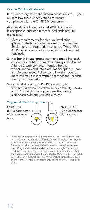
Custon Cabling Guidelines
If it is necessary to create custom cables on site, you must follow these specifications to ensure compliance with the Qt PRO™ equipment.
Any quality solid conductor 24 AWG CAT cable is acceptable, provided it meets local code require-ments and:
1) Meets requirements for plenum installation (plenum-rated) if installed in a return air plenum. Shielding is not required. Unshielded Twisted Pair (UTP) cable is satisfactory. Snagless boots are not required.
2) Has bent* 3-tyne (prong) contacts straddling each conductor in RJ-45 connectors. See graphic below. Aligned 2-tyne contacts intended for use with stranded conductors are not acceptable under any circumstances. Failure to follow this require-ment will result in intermittent contact and inconsis-tent system operation.
3) Once fabricated with RJ-45 connector, is field-tested before installation for continuity, shorts and 1:1 (straight through) connection using a standard network CAT cable tester.
2 types of RJ-45 connectors:
CORRECT INCORRECT RJ-45 connector RJ-45 connector with bent tyne with aligned tyne
* There are two types of RJ-45 connectors. The “bent 3-tyne” con-nector is intended for use with solid core CAT cable. The “aligned tyne” connector is intended for use with stranded CAT cable. Errors occur when incorrect cable/connector combinations are used. Diagram shows the end on a view of a single contact in a modular connector. The bent 3-tyne contact has the tines offset from each other to straddle the conductor. USE THE BENT 3-TYNE CONNECTOR FOR ALL Qt PRO™ INSTALLATIONS. Bent 3-tyne connectors are available at Home Depot and most CAT cable sup-pliers.
www.csmqt.com/qtprosupport 13
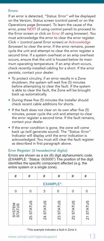
Errors
If an error is detected, “Status: Error” will be displayed on the Version, Status screen (control panel) or on the Operations page (browser). To learn the cause of the error, press NEXT (if using control panel) to proceed to the Error screen or click on Error (if using browser). You must acknowledge the error to clear the error register. Click + (control panel Error screen) or Acknowledge (browser) to clear the error. If the error remains, power cycle the unit and attempt to clear the error register a second time. If a system overheat or an amp overheat occurs, ensure that the unit is housed below its maxi-mum operating temperature. If an amp short occurs, check recently-installed cabling for a short. If the error persists, contact your dealer.
• To protect circuitry, if an error results in a Zone shutdown, the system will wait five (5) minutes before attempting to clear the fault. If the system is able to clear the fault, the Zone will be brought back up automatically.
• During these five (5) minutes the installer should check recent cable additions for shorts.
• If the fault does not clear on its own after five (5) minutes, power cycle the unit and attempt to clear the error register a second time. If the fault remains, contact your dealer.
• If the error condition is gone, the zone will come back up (will generate sound). The “Status: Error” Indicator will display until the error indication is acknowledged. You must still clear the fault register as described in first paragraph above.
Error Register: [6 hexadecimal digits]: Errors are shown as a six (6) digit alphanumeric code. (EXAMPLE: “Status: 003000”) The position of the digit identifies the specific component affected (e.g. the entire system or a single zone).
SYST
EM
STAT
US
Z5 S
TATU
S
Z4 S
TATU
S
Z3 S
TATU
S
Z2 S
TATU
S
Z1 S
TATU
S
# # # # # #
0 0 3 0 0 0
EXAMPLE*:
*This example indicates a fault in Zone 4.
14
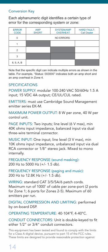
Conversion Key
SPECIFICATIONS
POWER SUPPLY: modular 100-240 VAC 50/60Hz 1.5 A input; 15 VDC 4A output; CE/UL/CUL rated.
EMITTERS: must use Cambridge Sound Management emitter series EK-M.
MAXIMUM POWER OUTPUT: 8 W per zone, 40 W per control unit.
PAGE INPUTS: Two inputs; line level (6 V max), min 40K ohms input impedance, balanced input via dual three-wire terminal connector.
MUSIC INPUT: One input; line level (3 V max), min 10K ohms input impedance, unbalanced input via dual RCA connector or 1/8" stereo jack. Mixed to mono internally.
FREQUENCY RESPONSE (sound masking): 200 Hz to 5000 Hz (+/- 1.5 db).
FREQUENCY RESPONSE (paging and music): 200 Hz to 12.8K Hz (+/- 1.5 db).
WIRING: standard CAT 3/5/5A/6 patch cords. Maximum run of 1000’ of cable per zone-port (2 ports for Zone 1; 6 ports for Zones 2-5). Maximum of 60 emitters per run.
DIGITAL COMPRESSION AND LIMITING: performed by on-board DSP.
OPERATING TEMPERATURE: 40-104°F, 4-40°C.
CONDUIT CONNECTORS: Unit is double-keyed to fit either 1/2" or 3/4" conduit connectors.
This equipment has been tested and found to comply with the limits for a Class A digital device, pursuant to part 15 of the FCC rules. These limits are designed to provide reasonable protection against
ERROR CODE
AMP SHORT
SYSTEM/AMP OVERHEAT
HARD FAULT: Call Dealer
NO ERRORS0
1
2
3
8, 9, A, B
Note that the specific digit can indicate multiple errors as shown in the table. For example, “Status: 003000” indicates both an amp short and an amp overheat in Zone 4.
Each alphanumeric digit identifies a certain type of error for the corresponding system or zone:

www.csmqt.com/qtprosupport 15
harmful interference when the equipment is operated in a commercial environment. This equipment generates, uses, and can radiate radio frequency energy and, if not installed and used in accordance with the instruction manual, may cause harmful interference to radio com-munications. Operation of this equipment in a residential area is likely to cause harmful interference in which case the user will be required to correct the interference at his/her own expense.
WARRANTY
Warranty Coverage — Qt Quiet technology™ emitters: Cambridge Sound Management, LLC (the “warrantor”) will, for a period of five (5) years, starting with the date of purchase, warrant that the Qt Quiet technology™ emitters (the “speakers”) will be free of defects in materials and workmanship that inter-fere with proper operation as a sound masking, paging and music speaker system. During that period, the war-rantor will, at its option, either (a) repair the speaker, or (b) replace the speaker. The decision to repair or replace will be made by the warrantor.
Warranty Coverage — Qt PRO™ control unit (QT-900/QT-1500): The warrantor will, for a period of one (1) year, starting with the date of purchase, warrant that the Qt PRO™ control unit (the “system”) will be free of defects in materials and workmanship that interfere with its proper operation as a sound masking, paging and music distribution control system. During that period, the warrantor will, at its option, either (a) repair the system, with new or refurbished parts, or (b) replace the system with a new or refurbished system of equal functionality at no charge. The decision to repair or replace will be made by the warrantor.
All software installed in the Qt PRO™ system is warranted to substantially conform to its published specifications. In no event does the warrantor warrant that the software is error free or that the customer will be able to operate the software without problems or interruptions. The warrantor will, from time to time make available software bug fixes. It is the responsibility of the purchaser to download and install these software modifications. Except for the forgoing, all software and software upgrades are provided AS IS.
The following terms apply to all: These warranty terms are extended only to the original purchaser of a new product. A purchase order or other proof of the original purchase date and purchaser is required for warranty service.
Full warranty terms are available at www.csmqt.com/qtprosupport
16 rev 07.09
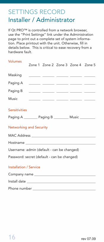
SETTINGS RECORD Installer / Administrator
If Qt PRO™ is controlled from a network browser, use the “Print Settings” link under the Administration page to print out a complete set of system informa-tion. Place printout with the unit. Otherwise, fill in details below. This is critical to ease recovery from a hardware fault.
Volumes Zone 1 Zone 2 Zone 3 Zone 4 Zone 5
Masking
Paging A
Paging B
Music
Sensitivities
Paging A Paging B Music
Networking and Security
MAC Address
Hostname
Username: admin (default - can be changed)
Password: secret (default - can be changed)
Installation / Service
Company name
Install date
Phone number