
VERSA SERIES - hytorctr.com
28
VERSA SERIES OPERATIONAL AND SPARE PARTS MANUAL MAN-VERSA-2012 Since 1968
Transcript of VERSA SERIES - hytorctr.com

VERSA SERIESOPERATIONAL AND SPARE PARTS MANUAL
MAN-VERSA-2012
Since 1968


STAY
SAFE
THANK YOU FOR PURCHASING THIS REVOLUTIONARY TORQUE/TENSION SYSTEM PLEASE CALL YOUR HYTORC REPRESENTATIVE TO SCHEDULE A FREE TRAINING THAT WILL
HELP YOU GET THE MOST OUT OF THIS ADVANCED BOLTING SYSTEM.
OPERATING CD: Please show the enclosed CD to your staff before each tool use to familiarize them with the tools.
FREE SAFETY TRAINING: To ensure safe operation, please request the FREE Safety Training before use by calling your local HYTORC Representative 1-800-367-4986 or www.hytorc.com. We recommend safety training every 6 months. These trainings are free of charge. Just call us. PLEASE READ THE SAFETY INSTRUCTIONS HEREIN.
SYSTEM INSPECTION: Before any use, please inspect the entire tool system, including hoses, gauge, sockets and backup wrenches. Do not use kinked hoses, oversized or heavily worn sockets, backup wrenches, damaged tools, pumps, connectors, or gauges. Connect system to operate from a safe distance. Ensure fasteners are in good shape. Check out tool functioning with drive or hex ratchet turning in one direction only and check out gauge from a safe distance that needle is on zero at no pressure and at 10,000 psi at high pressure. Keep high pressure on and check system visu-ally for leaks. Please keep in mind that hydraulic tools are very strong and work at high pressure.
HANDS-FREE BOLTING: The tool you have purchased permits hands-free operation from a safe distance in conjunction with a HYTORC Washer™. We recommend the use of a HYTORC Washer™ to avoid finger-pinching, over-crowded sites and to ensure hands-free bolting at least on all vertical and inverted applications, while eliminating improvisation and the use of reaction members or backup wrenches. Otherwise, set up the tool in a way that it does not have to be held by hand. For more information, please contact us at 1-800-367-4986 or www.hytorc.com.
HANDS-FREE WASHER APPLICATION: Make sure the drive and the tool are locked on securely.
FREE ANNUAL TOOL INSPECTION: With the purchase of HYTORC, you have the right to a FREE annual tool inspection, which includes free seals, springs, connectors, and free lubrication. In case of damaged or worn parts, the first inspection within 12 months of purchase is free of charge. Thereafter, you will be informed of any cost prior to replacement. Any part replaced and charged by us will be sent to you for your inspection upon request when P.O. is issued.
FREE LOANER TOOLS: In case of tool failure during the warranty or rental period, please contact your local HYTORC Agent for a free loaner tool - 24/7.
HOSE REPLACEMENT: We recommend replacing hydraulic hoses and oil every (3) three months.
PLEASE WEAR REQUIRED SAFETY ATTIRE and use common sense during operation.
HELP: If you require any further assistance, please call your local HYTORC Representative or1-800-FOR-HYTORC (1-800-367-4986), on the web at www.hytorc.com - 24/7! It’s live!
PLEASE REVIEW THESE SAFETY TIPS BEFORE EVERY TOOL USE
No. Safety 1-2-1009


CONTENTS
VERSA SERIESOPERATIONAL AND SPARE PARTS MANUAL
INTRODUCING HYTORC 6SECTION IIMPORTANT SAFETY INSTRUCTIONS 7SECTION IIINSTRUCTIONS BEFORE USE 92-1 Working Pressure2-2 Hydraulic Connections2-3 Electrical Connections2-4 Air Connections
SECTION IIIOPERATION 113-1 General3-2 Connecting the System3-3 Inserting the Ratchet Link3-5 Setting Torque 3-5 Setting Pressure3-6 Applying Torque3-7 Operating the Torque Machine3-8 Loosening Procedures
SECTION IVHYTORC POWER PACKS 164-1 General4-2 Remote Control4-3 Operation
SECTION VPREVENTIVE MAINTENANCE 185-1 Preventive Maintenance - Torque Machines5-2 Preventive Maintenance - Hydraulic Power Packs
SECTION VITROUBLESHOOTING 20
APPENDICES 24 A VERSA Tool Parts List B VERSA Low Clearance Link Parts ListC VERSA Dimensional DataD Square/Allen Drive Working Torque
INTRODUCING HYTORC
THANK YOU FOR BUYING HYTORC!YOU ARE NOW HOLDING ONE OF THE WORLD'S LARGEST SELLING ANDMOST ADVANCED HYDRAULIC TORQUE/TENSION TOOLS.
HYTORC is used more often, by more industries on more applications than all others combined. If you maintain your new tool properly, it will last for years to come.
This manual is designed to provide you with the basic knowledge required to operate and maintain your HYTORC tool. Please read this manual carefully and follow the instructions provided. If you have any questions regarding your HYTORC tool, please call us directly at 201-512-9500 or fax 201-512-0530.
Finally, your purchase of this HYTORC tool entitles you to the following FREE services:
• Free on-site training in the application and operation of your HYTORC equipment
• Free semi-annual training
• Free annual tool inspection
• Free loaner tools in case of failure
• Free engineering assistance by calling 1 800 FOR-HYTORC, or our continental office
Your local HYTORC office was informed of the delivery of this equipment. Should you require immediate training, please feel free to call us directly to arrange an appointment with you at your convenience.
An instructional CD is also available for basic training and occasional brush up on operating procedures.
For additional information please visit our website at www.hytorc.com
Again, thank you and welcome to HYTORC!
Worldwide WarrantyHYTORC equipment is engineered to the latest technological standards and is backed by our exclusive 12-word, 12-month warranty.
"YOU BREAK IT UNDER NORMAL USE, WE FIX IT FREE OF CHARGE!"
If a HYTORC Tool cannot be repaired on-site, FREE loaner HYTORC equipment will be made available to you upon request.UNEX CORPORATION OR ITS DEALERS SHALL NOT BE LIABLE FOR LOSS OF PRODUCT OR OTHER INCIDENTAL OR CONSEQUENTIAL COSTS INCURRED BY THE BUYER OR THE USER.
HYTORC Offices WorldwideEurope HYTORC Europe Tel. 33-1-4288-6745
Japan HYTORC Japan Tel. 81-3-3314-3315
Australia HYTORC Australia Tel. 61-8-8293-8411
United Kingdom HYTORC UK Tel. 44-16-7036-3800
Brazil HYTORC South America Tel. 55-21-2223-2944
All Others HYTORC USA Tel. 201-512-9500 /800-FOR-HYTORC
6 Leading Innovation in Torque and Tension Since 1968
The World’s Most Trusted Industrial Torque and Tension Systems
SECTION I
IMPORTANT SAFETY INSTRUCTIONSWARNING: Your HYTORC TORQUE/TENSION MACHINE is a power tool, and as with any power tool, certain safety precautions should be observed to avoid accidents or personal injury. The following tips will assist you.
• READ ALL INSTRUCTIONS
• KEEP WORK AREA CLEAN AND WELL LIT
• CONSIDER WORK AREA ENVIRONMENT Electrical Pumps should never be used in any atmosphere which can be considered potentially volatile. If there is any doubt, use an air pump. Note: metal to metal contact can cause sparks, precautions should be taken.
• AVOID PREMATURE TOOL STARTING The Pump Remote Control is for the TOOL OPERATOR only. Avoid separate pump and tool operator.
• STAY CLEAR DURING OPERATION In most cases, the tool will allow “hands free” operation. If the tool must be held or steadied during operation, use alternative means of securing the tool to the application.
• GUARD AGAINST ELECTRIC SHOCK Ensure the pump is properly grounded and the proper voltage is being used.
• STORE IDLE TOOLS When not in use, tools and accessories should be properly stored to avoid deterioration.
• USE THE RIGHT TOOL Don’t force small tools or attachments to do the job of a larger tool. Don’t use a tool for purposes not intended. HYTORC can develop custom accessories for your job to ensure safe and simple operation. Contact your local HYTORC representative for more information on our custom engineering abilities.
• PROPER SAFETY ATTIRE When handling/operating hydraulic equipment, use work gloves, hard hats, safety shoes, hearing protection, and other applicable clothing.
• USE SAFETY GLASSES
• MOVING EQUIPMENT Do not use hydraulic hoses, uni-swivels, pump power or remote cords as means of moving the equipment.
7
The World’s Most Trusted Industrial Torque and Tension Systems
Leading Innovation in Torque and Tension Since 1968
• HOSES Do not kink hoses. Inspect and replace if damaged.
• SHROUDS AND COVER PLATES All tools are equipped with shrouds and/or cover plates to cover up moving internal parts. If shrouds are missing or damaged, please contact your local HYTORC representative for repair. A free loaner tool will be made available to you during the time of repair.
• MAINTAIN TOOLS WITH CARE For top performance, inspect tool powerpack, hoses, connectors, electric lines, and accessories for visual damage frequently. Always follow instructions for proper tool and pump maintenance. Refer to the Operations Maintenance Section for further clarification.
• STAY ALERT Watch what you are doing. Use common sense. Do not use power equipment under the influence of any mood altering substances.
• PRIOR TO OPERATION Ensure that all hydraulic connections are securely connected. Verify that the hydraulic hoses are not kinked. Ensure the square drive and its retainer are fully and securely engaged.
• PRIOR TO USE Cycle tool to ensure proper function. Locate a solid, secure reaction point. Be sure the reaction arm retain-ing clamp is fully engaged. Be sure the hydraulic hoses are free and clear of the reaction point. Pressurize the system momentarily; if the tool tends to “ride up” or to “creep”, stop and re-adjust the reaction arm to a more solid and secure position. NOTE: For additional safety, a HYTORC Washer can be used in place of the reaction arm; call your HYTORC representative for more information.
• ALWAYS USE QUALITY ACCESSORIES Always use top quality impact sockets in good condition which are the correct size and fully engage the nut. Hidden flaws, however, remain a possibility which could cause breakage, so stay clear of sockets during operation.
• DO NOT USE FORCE Do not hammer on the socket or the tool to enhance performance. If the nut will not turn with the wrench you are using, use a larger size HYTORC tool.
• REACTION ARM Proper reaction is required. Adjust reaction arm or plate accordingly. Avoid excessive play. In case of questions, consult with your local HYTORC office.
8 Leading Innovation in Torque and Tension Since 1968
The World’s Most Trusted Industrial Torque and Tension Systems
SECTION II
INSTRUCTIONS BEFORE USEREAD CAREFULLY: Most malfunctions in new equipment are the result of improper operation and/or set-up assembly.
PREPARATION: Remove HYTORC Torque Machine from shipping container.
INSPECTION: Visually inspect all components for shipping damage. If any damage is found, notify carrier immediately.
2-1Working PressureThe tool’s maximum working pressure is 10,000 PSI (700kg/cm2).
Make sure that all hydraulic equipment used with this tool is rated for 10,000 PSI Operating Pressure.
2-2Hydraulic ConnectionsWith older style pumps (SST-IO, SST-20), the retract side of the system may remain pressurized after the pump hasbeen switched “off’. This trapped pressure makes it impossible to loosen the retract-side fittings by hand.
To release the pressure, find the 5/16” manual override holes in the end ofthe black solenoids on the pump. With a welding rod, allen key or similar device, push in on the ends of both solenoids, each in turn, and the residual pressure will be released. All fittings will then be hand tight again.
Newer style pumps (HYTORC 115, HYTORC 230, HYTORC AIR) are equipped with an auto-pressure relief.
Never disconnect or connect any hydraulic hoses or fittings without first unloading the wrench and the pump. If the system includes a gauge, double check the gauge to ensure pressure has been released.
When making connections with quick disconnect couplings, make sure the couplings are fully engaged.Threaded connections such as fittings, gauges, etc., must be clean, securely tightened, and leak free.
CAUTION: Loose or improper threaded fittings can be potentially dangerous if pressurized, yet, severe over tightening can cause premature thread failure. Fittings need only to be securely tightened & leak free. Never grab, touch or in any way come in contact witb a hydraulic pressure leak. Escaping oil could penetrate the skin and cause injury.
9
The World’s Most Trusted Industrial Torque and Tension Systems
Leading Innovation in Torque and Tension Since 1968
2-3Electrical ConnectionsEnsure proper power availability to prevent motor failure or dangerous electrical overloading. Compare themotor nameplate for required amperage.
Do not use electric pump if the 3-prong electrical plug is not whole.
Minimize the length of extension cords and be sure they are of adequate wire size, with ground connections.Extension cord should be #10 AWG gauge.
WARNING: Electric motors may spark. Do not operate in an explosive atmosphere or in thepresence of conductive liquids. Use an air motor pump Instead.
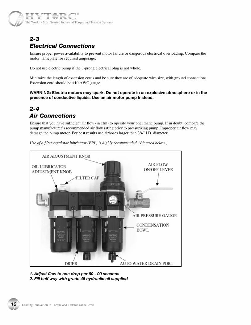
2-4Air ConnectionsEnsure that you have sufficient air flow (in cfm) to operate your pneumatic pump. If in doubt, compare thepump manufacturer’s recommended air flow rating prior to pressurizing pump. Improper air flow maydamage the pump motor. For best results use airhoses larger than 3/4” I.D. diameter.
Use of a filter regulator lubricator (FRL) is highly recommended. (Pictured below.)
1. Adjust flow to one drop per 60 - 90 seconds2. Fill half way with grade 46 hydraulic oil supplied
10 Leading Innovation in Torque and Tension Since 1968
The World’s Most Trusted Industrial Torque and Tension Systems

SECTION III
OPERATION3-1GeneralAll HYTORC Torque Machines are supplied completely assembled and ready for use. A HYTORC HydraulicPower Pack (for use with your HYTORC machine) is recommended to provide the speed, pressure, andportability that makes your HYTORC System efficient and accurate.
The System accuracy of your HYTORC tool is +/- 3%, based upon manufacturer’s specifications. Thisaccuracy may be certified through calibration by HYTORC or any other qualified calibration facility whoseprogram is traceable to the National Institute of Standards and Technology (N.I.S.T.).
Using a calibrated gauge enhances the accuracy of your HYTORC System.
3-2Connecting the SystemThe wrench head and power pack are connected by a 10,000 PSI operating pressure (40,000 PSI burst)twinline hose assembly. Each end of the hose will have one male and one female connector to assure properinterconnection between pump and wrench heads.
IMPORTANT: To avoid tool malfunction. Do not reverse connectors.
Connect the twinline hose to the uni-swivel as shown below:
Insure the connectors are fully engaged and screwed snugly and completely together.
11
The World’s Most Trusted Industrial Torque and Tension Systems
Leading Innovation in Torque and Tension Since 1968

3-3Inserting the Ratchet Link The “hook” on the end of the power head is inserted into the cutout on the top of the link plates. The power head is then swung down to rest along the base of the link side plate. At this point, the link pin hole of the power head andlink will align. Insert the link pin to secure.
Torquing Proceedures
Select the appropriate size low clearance ratchet link and insert it into the tool.
The VERSA low clearance ratchet links are supplied complete with a long reaction block. This reaction block is designed to react against an adjacent nut on most normal flange type applications. Before operating the tool, place the tool with the low clearance link on the nut to be tightened/loosened. If the reaction block abuts against an adjacent nut or to some other secure stationary object, then use of the reaction block is appropriate.
Reaction Block
If, however, bolt spacing is such that the reaction block does not reach the adjacent bolt, use of the short reaction arm is indicated. This will allow reaction to be taken against the side of the flange. To attach the short reaction arm, remove the standard link retaining pin, align with the holes of the short reaction arm with those of the reaction block and insert the long link retaining pin to secure. Insure that the arm extends in the appropriate direction: right for tightening; left for loosening.
Reaction Block
Link Pin
Hook
Link Pin
Ready for Use
Cutout
Long Retaining Pin
12 Leading Innovation in Torque and Tension Since 1968
The World’s Most Trusted Industrial Torque and Tension Systems
3-4Setting Torque
Once the system is fully connected and the proper power supply is available, it is time to adjust the pump pressureto the level needed on your job.
When tightening, use the manufacturer’s specifications to determine the torque value which you will ultimately require.
Torque sequence may vary from plant to plant and even within individual plants, depending upon the gasket material, etc. Always abide by local procedures.
The included torque chart is a guideline for comparison only and gives typical torque values specified for the mostcommonly encountered fasteners.
Next, find the pressure-torque conversion table applicable to the tool which you intend to use.
An example of finding the desired torque required is as follows: Assume you are going to use a HYTORCVERSA tool to torque a 1-1/4” bolt to 1,265 ft. lbs.
Start by going to the torque chart that was shipped with the tool. On the torque chart read left-to-right across the topline to the column VERSA.
Start by referring to the pressure-torque conversion table for the tool you are using and read left-to-right across thetop line to the rightmost column.
Now using 1,280 ft. lbs., read back to the left on that same line and read the pump pressure, under the PSI column, 4,000PSI.
To be technically correct, you should diminish that 4,000PSI by 1.5% ( to 3,940), but 1,280 is well within the tool’s +/-3% accuracy range, so proceed to set 4,000PSI on your pump’s regulator valve.
13
The World’s Most Trusted Industrial Torque and Tension Systems
Leading Innovation in Torque and Tension Since 1968
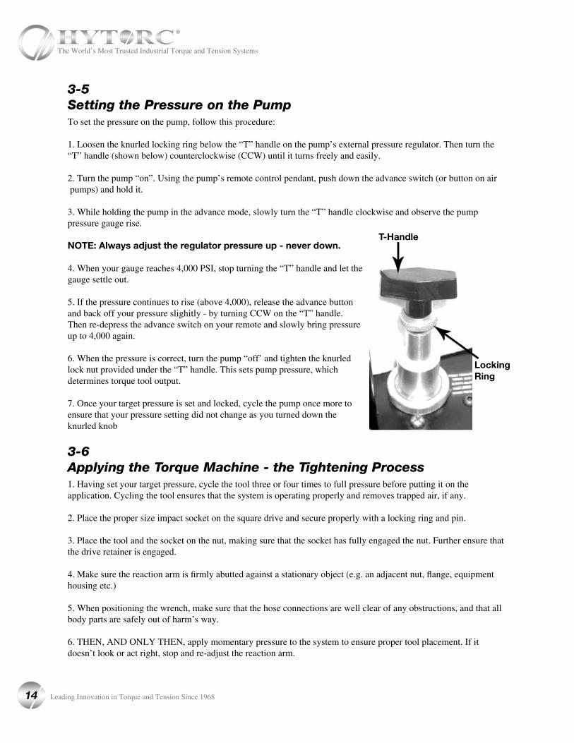
3-5Setting the Pressure on the PumpTo set the pressure on the pump, follow this procedure:
1. Loosen the knurled locking ring below the “T” handle on the pump’s external pressure regulator. Then turn the “T” handle (shown below) counterclockwise (CCW) until it turns freely and easily.
2. Turn the pump “on”. Using the pump’s remote control pendant, push down the advance switch (or button on air pumps) and hold it.
3. While holding the pump in the advance mode, slowly turn the “T” handle clockwise and observe the pump pressure gauge rise.
NOTE: Always adjust the regulator pressure up - never down.
4. When your gauge reaches 4,000 PSI, stop turning the “T” handle and let the gauge settle out.
5. If the pressure continues to rise (above 4,000), release the advance button and back off your pressure slighitly - by turning CCW on the “T” handle. Then re-depress the advance switch on your remote and slowly bring pressure up to 4,000 again.
6. When the pressure is correct, turn the pump “off’ and tighten the knurled lock nut provided under the “T” handle. This sets pump pressure, which determines torque tool output.
7. Once your target pressure is set and locked, cycle the pump once more to ensure that your pressure setting did not change as you turned down the knurled knob
3-6Applying the Torque Machine - the Tightening Process1. Having set your target pressure, cycle the tool three or four times to full pressure before putting it on theapplication. Cycling the tool ensures that the system is operating properly and removes trapped air, if any.
2. Place the proper size impact socket on the square drive and secure properly with a locking ring and pin.
3. Place the tool and the socket on the nut, making sure that the socket has fully engaged the nut. Further ensure that the drive retainer is engaged.
4. Make sure the reaction arm is firmly abutted against a stationary object (e.g. an adjacent nut, flange, equipment housing etc.)
5. When positioning the wrench, make sure that the hose connections are well clear of any obstructions, and that all body parts are safely out of harm’s way.
6. THEN, AND ONLY THEN, apply momentary pressure to the system to ensure proper tool placement. If it doesn’t look or act right, stop and re-adjust the reaction arm.
Locking Ring
T-Handle
14 Leading Innovation in Torque and Tension Since 1968
The World’s Most Trusted Industrial Torque and Tension Systems
3-7Operating the Torque Machine
1. By pushing down on the remote control button in the advance position, the rear of the tool will be pushed backuntil the reaction arm makes contact with its reaction point.
2. Continue to hold down the button as the socket turns until you hear an audible “click” which will signify the hydraulic cylinder inside the tool is fully extended and will not turn the socket further.
3. Continuing to hold down the remote control button will result in a rapid buildup of pressure to the point of where the gauge reads what was preset prior to applying the wrench.
IMPORTANT: The reading of full preset pressure after the cylinder is extended DOES NOTINDICATE that this pressure (torque) is applied to the bolt. It only indicates that the cylinder is fullyextended and cannot turn the socket further until the tool automatically resets itself.
Releasing the remote control button will retract the cylinder. The tool will automatically reset itself and the operatorwill hear an audible “click” indicating he can again push the remote control button and the socket will turn. Each time the cylinder is extended and retracted, it is called a cycle. Successive cycles are made until the tool “stalls” at the pre-set Torque/PSI with an accuracy of ±3% and ±1%. Repeatability is +1 -1%.
IMPORTANT: ALWAYS ATTEMPT ONE FINAL CYCLE TO INSURE THE “STALL” POINT HAS BEENREACHED.
3-8Loosening ProceduresFirst, set the pump to 10,000 PSI. Change the drive and the reaction arm to the loosening mode, assurring thereaction arm abuts squarely off a solid reaction point. Press and hold the remote control button down. Pressure will decrease as the socket begins to turn. As the cylinder extends fully, you will hear an audible “click”. Release the remote control button, and the cylinder automatically retracts, at which time you again hear the audible “click”. Repeat this process until the fastener can be removed by hand.
NOTE: IF THE BOLT DOES NOT LOOSEN WITH THE ABOVE PROCEDURE, IT IS AN INDICATIONTHAT YOU REQUIRE THE NEXT LARGER SIZE TOOL TO LOOSEN THE BOLT.
15
The World’s Most Trusted Industrial Torque and Tension Systems
Leading Innovation in Torque and Tension Since 1968
SECTION IV
HYTORC POWER PACKS4-1General InformationAll HYTORC Power Packs operate in a pressure range from 500 to 10,000 PSI and are fully adjustable. They have been engineered and designed for portability and high flow for increased speed. Before using your HYTORC powerpack, check the following points:
• Is the reservoir filled with oil?
• Where is the closest electrical outlet at the job site?
• Is there enough air pressure (100 PSI) and flow at the job site? (Air units only)
• Is the gauge mounted and rated for 10,000 PSI?
• Is the oil filler plug securely in place?
4-2Working PressureThe Pump’s maximum working pressure is 10,000 PSI(700 kg/cm2). Make sure all hydraulic equipment andaccessories are rated for 10,000 PSI operating pressure.
4-3Hydraulic ConnectionsNever disconnect or connect hydraulic hoses or fittings without first unloading the wrench. Unplug the electrical cord of the pump, and open all hydraulic controls several times to ensure that the system has been depressurized. Ifthe system includes a gauge, double check the gauge to ensure pressure has been released.
When making a connection with quick disconnect couplings, make sure the couplings are fully engaged.Threaded connections such as fittings, gauges etc. must be clean, securely tightened, and leak free.
CAUTION: Loose or improperly threaded couplers can be potentially dangerous if pressurized. However, severe over tightening can cause premature thread failure. Fittings need to be onlytightened secure and leak free. Never grab, touch, or in any way come in contact with a hydraulicpressure leak. Escaping oil could penetrate the skin and cause injury.
Do not subject the hose to potential hazards such as sharp surfaces, extreme heat or heavy objects. Do not allow the hose to kink and twist. Inspect the hose for wear before it is used.
16 Leading Innovation in Torque and Tension Since 1968
The World’s Most Trusted Industrial Torque and Tension Systems
4-4Electrical Power1. CHECK FOR PROPER ELECTRICAL SUPPLY BEFORE CONNECTING.
2. THIS MOTOR MAY SPARK. DO NOT OPERATE IN AN EXPLOSIVE ATMOSPHERE OR IN PRESENCEOF CONDUCTIVE LIQUIDS. a. Do not use a power or extension cord that is damaged or has exposed wiring. b. All single phase motors come equipped with a three prong grounding type plug to fit the proper grounded
type electrical outlet. Do not use a two prong ungrounded extension cord as the pump’s motor must be grounded.
3. COMPARE MOTOR NAMEPLATE AGAINST POWER AVAILABILITY TO PREVENT MOTOR BURNOUT OR DANGEROUS ELECTRICAL OVERLOADING.
4-5Prior to Use Check hydraulic oil level to prevent possible pump burnout. Open the filler plug located on the reservoir plate. Look at the oil fill level on the oil sight gauge. The oil level should be about 2” from the top of the reservoir plate with the motor off. Add HYTORC oil as necessary. Do not mix different grades of oil.
Make sure all desired gauge, valve, hose, and quick coupler connections are tight and secure before operating.
The use of a pressure gauge is required for normal pump operation. Mounted on the manifold, the gauge permits theoperator to monitor the load on the wrench. 114% calibrated gauges are available for most applications.
4-6OperationBefore starting your Electric Pump (HYTORC 115/230), connect your hydraulic hoses to both the pump andtorque wrench.
Place the toggle switch in the ON position and the rocker switch on the hand control pendant in the OFF position.To start the pump, depress and release the yellow safety button.
NOTE: The safety button is an added feature designed to prevent premature starting and shouldonly be depressed by the tool operator.
Push the rocker switch to advance and release. This will start your pump and place it in the retract position.
NOTE: Read the section labeled HYTORC OPERATIONS and SETTING TORQUE prior to installingthe torque wrench onto the application.
Your HYTORC 115/230 hydraulic pump has been designed with an auto shut off system. The pump will shut off after about 30 seconds of non-cycling. This will prevent overheating and unnecessary wear, which will prolong the life of your pump. To restart the pump, the yellow safety button must again be depressed before use.
17
The World’s Most Trusted Industrial Torque and Tension Systems
Leading Innovation in Torque and Tension Since 1968
SECTION VI
PREVENTIVE MAINTENANCE 5-1Preventive Maintenance -Torque MachinesTool failure, although rare, does occur. Such failure is most often in the hydraulic couplers or hoses. These items are repairable or replaceable immediately, since they are available universally. Failure of structural members of the tool are quite rare, but replacement parts are available from stock. All repairs to HYTORC tools may be made by reasonably experienced individuals according to these instructions.
• Lubrication
All moving parts should periodically be coated with a good quality NLGI #2 molybdenum disulfide grease. Under harsh environmental conditions, cleaning and lubricating should be performed more frequently.
• Hydraulic Hoses
Hoses should be checked for cracks and leaks before and after each job. Hydraulic fittings can become plugged with dirt and
should be flushed periodically.
• Quick-Connects Fittings should be kept clean and not allowed to be dragged along the ground or floor, as even small particles of dirt can cause the internal valves to malfunction.
• Springs
Springs are used for the drive pawl assembly and for the accuracy assurance pawl. These springs can be replaced if necessary.
• Cylinder Seals
If the cylinder requires disassembly, it is recommended that the cylinder seals be replaced at the same time. Seal kits are readily available.
• Structural Members
All structural parts on the tool should be inspected once a year to determine if there are any cracks, chips, or deformities. If so, immediate replacement is required.
18 Leading Innovation in Torque and Tension Since 1968
The World’s Most Trusted Industrial Torque and Tension Systems
5-2Preventive Maintenance -Hydraulic Power PacksHYTORC Hydraulic Power Packs are precision-built units and, as such, do require a certain amount of care and maintenance.
• Hydraulic Oil
Oil should be completely changed after every 40 hours of operation, or at least twice a year. Always make sure the reservoir is filled with fluid. If additional oil is required, use only high-grade hydraulic oil.
• Quick-Disconnects
Fittings should be checked periodically for leaks. Dirt or foreign materiais should be kept away from fittings. Clean before use.
• Hydraulic Gauge
Some gauges are liquid filled. Should this liquid level drop, it indicates external leakage, and replacement is necessary. Should the gauge fill with hydraulic oil, it indicates internal failure and it should be discarded.
• Filter on Pump
The filter should be replaced twice a year in normal use and more often if the pump is used daily or in a dirty, harsh environment.
• Remote Control
(Air Unit) The air line to the remote control unit should be checked for obstructions or kinks in the line periodically. If there is a bend or break in the line, it must be replaced. The spring-loaded buttons on the remote handle should bechecked in the event of operating difficulties. (Electric Unit) The rocker switch should be checked periodically if any indication of problems exist.
• Air Valve
This valve should be checked twice a year.
• Brushes and Brush Holders
(Electric Unit) Check and replace, if worn.
• Armature
(Electric Unit) Check yearly.
19
The World’s Most Trusted Industrial Torque and Tension Systems
Leading Innovation in Torque and Tension Since 1968
SECTION VI
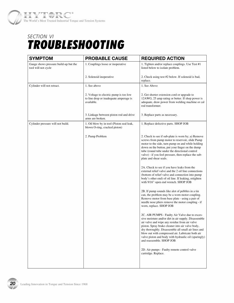
TROUBLESHOOTING
SYMPTOM PROBABLE CAUSE REQUIRED ACTIONGauge shows pressure build-up but the tool will not cycle
1. Couplings loose or inoperative
2. Solenoid inoperative
1. Tighten and/or replace couplings. Use Test #1 listed below to isolate problem.
2. Check using test #2 below. If solenoid is bad, replace.
Cylinder will not retract. 1. See above
2. Voltage to electric pump is too low to line drop or inadequate amperage is available.
3. Linkage between piston rod and drive arms are broken.
1. See Above
2. Get shorter extension cord or upgrade to 12AWG, 25 amp rating or better. If shop power is adequate, draw power from welding machine or cal rod transformer.
3. Replace parts as necessary.
Cylinder pressure will not build. 1. Oil blow by in tool (Piston seal leak, blown O-ring, cracked piston)
2. Pump Problem
1. Replace defective parts. SHOP JOB
2. Check to see if sub-plate is worn by; a) Remove screws from pump motor to reservoir, slide Pump motor to the side, turn pump on and while holding down on the button, put your finger on the dump tube (round tube under the directional control valve) - if you feel pressure, then replace the sub-plate and shear seals.
2A. Check to see if you have leaks from the external relief valve and the 2 oil line connections (bottom of relief valve and connection into pump body’s other end) of oil line. If leaking, retighten with 9/16” open end wrench. SHOP JOB
2B. If pump sounds like alot of pebbles in a tin can, the problem may be a worn motor coupling. Remove motor from base plate - using a pair of needle nose pliers remove the motor coupling - if worn, replace. SHOP JOB
2C. AIR PUMPS - Faulty Air Valve due to exces-sive moisture and/or dirt in air supply. Disassemble air valve and wipe any residue from air valve piston. Spray brake cleaner into air valve body, dry thoroughly. Disassemble all small air lines and blow out with compressed air. Lubricate both air valve piston and body with hydraulic oil (sparingly) and reassemble. SHOP JOB
2D. Air pumps - Faulty remote control valve cartridge. Replace.
20 Leading Innovation in Torque and Tension Since 1968
The World’s Most Trusted Industrial Torque and Tension Systems
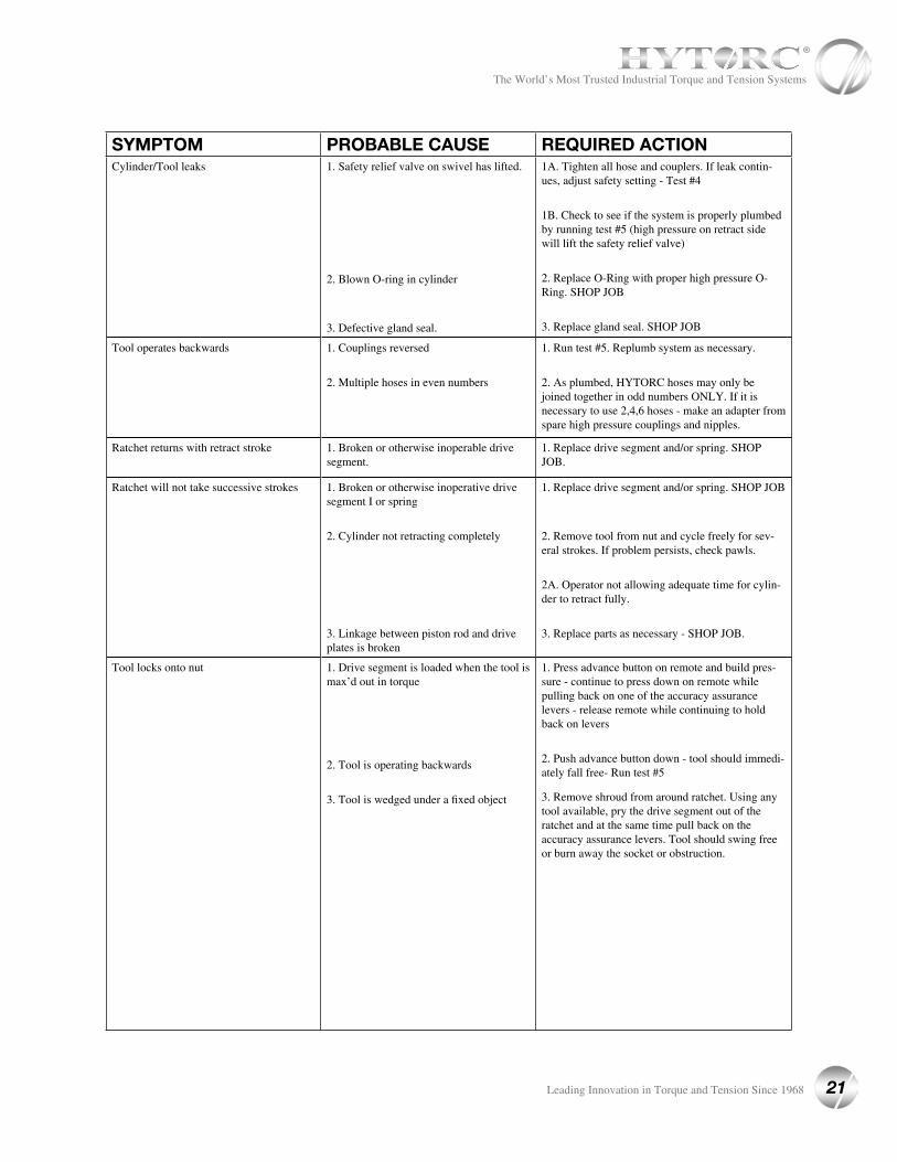
SYMPTOM PROBABLE CAUSE REQUIRED ACTIONCylinder/Tool leaks 1. Safety relief valve on swivel has lifted.
2. Blown O-ring in cylinder
3. Defective gland seal.
1A. Tighten all hose and couplers. If leak contin-ues, adjust safety setting - Test #4
1B. Check to see if the system is properly plumbed by running test #5 (high pressure on retract side will lift the safety relief valve)
2. Replace O-Ring with proper high pressure O-Ring. SHOP JOB
3. Replace gland seal. SHOP JOB
Tool operates backwards 1. Couplings reversed
2. Multiple hoses in even numbers
1. Run test #5. Replumb system as necessary.
2. As plumbed, HYTORC hoses may only be joined together in odd numbers ONLY. If it is necessary to use 2,4,6 hoses - make an adapter from spare high pressure couplings and nipples.
Ratchet returns with retract stroke 1. Broken or otherwise inoperable drive segment.
1. Replace drive segment and/or spring. SHOP JOB.
Ratchet will not take successive strokes 1. Broken or otherwise inoperative drive segment I or spring
2. Cylinder not retracting completely
3. Linkage between piston rod and drive plates is broken
1. Replace drive segment and/or spring. SHOP JOB
2. Remove tool from nut and cycle freely for sev-eral strokes. If problem persists, check pawls.
2A. Operator not allowing adequate time for cylin-der to retract fully.
3. Replace parts as necessary - SHOP JOB.
Tool locks onto nut 1. Drive segment is loaded when the tool is max’d out in torque
2. Tool is operating backwards
3. Tool is wedged under a fixed object
1. Press advance button on remote and build pres-sure - continue to press down on remote while pulling back on one of the accuracy assurance levers - release remote while continuing to hold back on levers
2. Push advance button down - tool should immedi-ately fall free- Run test #5
3. Remove shroud from around ratchet. Using any tool available, pry the drive segment out of the ratchet and at the same time pull back on the accuracy assurance levers. Tool should swing free or burn away the socket or obstruction.
21
The World’s Most Trusted Industrial Torque and Tension Systems
Leading Innovation in Torque and Tension Since 1968
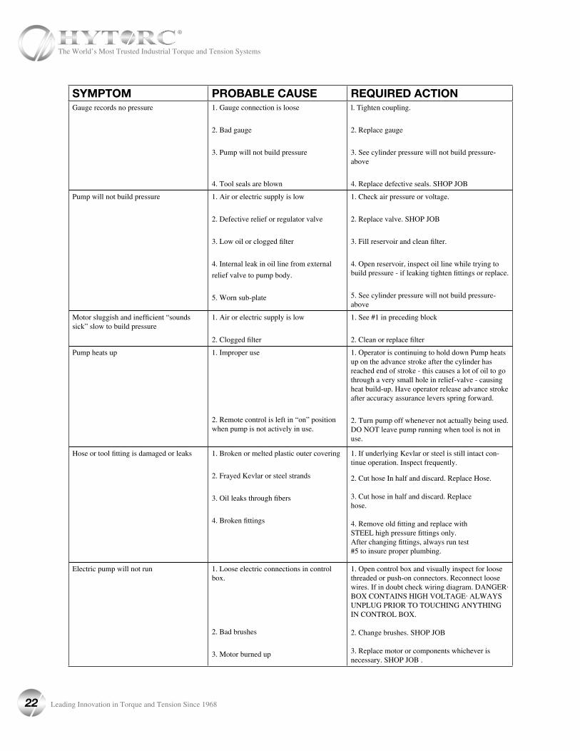
SYMPTOM PROBABLE CAUSE REQUIRED ACTIONGauge records no pressure 1. Gauge connection is loose
2. Bad gauge
3. Pump will not build pressure
4. Tool seals are blown
l. Tighten coupling.
2. Replace gauge
3. See cylinder pressure will not build pressure-above
4. Replace defective seals. SHOP JOB
Pump will not build pressure 1. Air or electric supply is low
2. Defective relief or regulator valve
3. Low oil or clogged filter
4. Internal leak in oil line from external
relief valve to pump body.
5. Worn sub-plate
1. Check air pressure or voltage.
2. Replace valve. SHOP JOB
3. Fill reservoir and clean filter.
4. Open reservoir, inspect oil line while trying to build pressure - if leaking tighten fittings or replace.
5. See cylinder pressure will not build pressure-above
Motor sluggish and inefficient “sounds sick” slow to build pressure
1. Air or electric supply is low
2. Clogged filter
1. See #1 in preceding block
2. Clean or replace filter
Pump heats up 1. Improper use
2. Remote control is left in “on” position when pump is not actively in use.
1. Operator is continuing to hold down Pump heats up on the advance stroke after the cylinder has reached end of stroke - this causes a lot of oil to go through a very small hole in relief-valve - causing heat build-up. Have operator release advance stroke after accuracy assurance levers spring forward.
2. Turn pump off whenever not actually being used. DO NOT leave pump running when tool is not in use.
Hose or tool fitting is damaged or leaks 1. Broken or melted plastic outer covering
2. Frayed Kevlar or steel strands
3. Oil leaks through fibers
4. Broken fittings
1. If underlying Kevlar or steel is still intact con-tinue operation. Inspect frequently.
2. Cut hose In half and discard. Replace Hose.
3. Cut hose in half and discard. Replacehose.
4. Remove old fitting and replace withSTEEL high pressure fittings only.After changing fittings, always run test#5 to insure proper plumbing.
Electric pump will not run 1. Loose electric connections in control box.
2. Bad brushes
3. Motor burned up
1. Open control box and visually inspect for loose threaded or push-on connectors. Reconnect loose wires. If in doubt check wiring diagram. DANGER· BOX CONTAINS HIGH VOLTAGE· ALWAYS UNPLUG PRIOR TO TOUCHING ANYTHING IN CONTROL BOX.
2. Change brushes. SHOP JOB
3. Replace motor or components whichever is necessary. SHOP JOB .
22 Leading Innovation in Torque and Tension Since 1968
The World’s Most Trusted Industrial Torque and Tension Systems
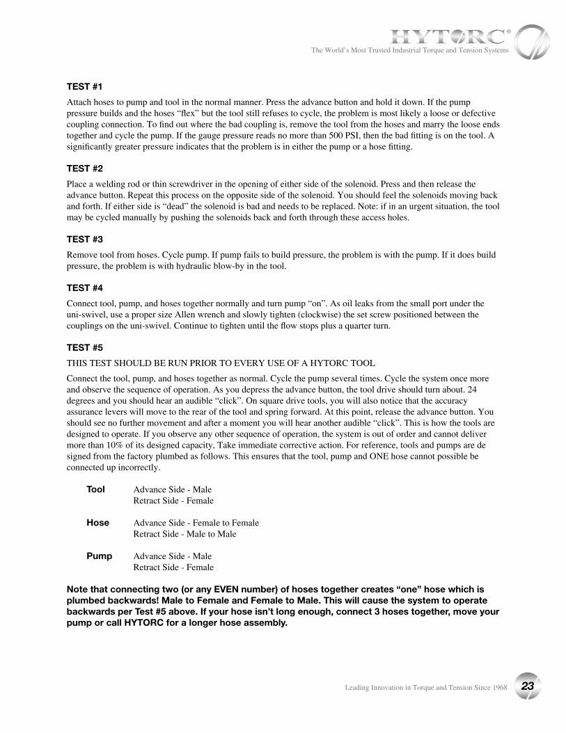
TEST #1
Attach hoses to pump and tool in the normal manner. Press the advance button and hold it down. If the pump pressure builds and the hoses “flex” but the tool still refuses to cycle, the problem is most likely a loose or defective coupling connection. To find out where the bad coupling is, remove the tool from the hoses and marry the loose ends together and cycle the pump. If the gauge pressure reads no more than 500 PSI, then the bad fitting is on the tool. A significantly greater pressure indicates that the problem is in either the pump or a hose fitting.
TEST #2
Place a welding rod or thin screwdriver in the opening of either side of the solenoid. Press and then release the advance button. Repeat this process on the opposite side of the solenoid. You should feel the solenoids moving back and forth. If either side is “dead” the solenoid is bad and needs to be replaced. Note: if in an urgent situation, the tool may be cycled manually by pushing the solenoids back and forth through these access holes.
TEST #3
Remove tool from hoses. Cycle pump. If pump fails to build pressure, the problem is with the pump. If it does build pressure, the problem is with hydraulic blow-by in the tool.
TEST #4
Connect tool, pump, and hoses together normally and turn pump “on”. As oil leaks from the small port under the uni-swivel, use a proper size Allen wrench and slowly tighten (clockwise) the set screw positioned between the couplings on the uni-swivel. Continue to tighten until the flow stops plus a quarter turn.
TEST #5
THIS TEST SHOULD BE RUN PRIOR TO EVERY USE OF A HYTORC TOOL
Connect the tool, pump, and hoses together as normal. Cycle the pump several times. Cycle the system once more and observe the sequence of operation. As you depress the advance button, the tool drive should turn about. 24 degrees and you should hear an audible “click”. On square drive tools, you will also notice that the accuracy assurance levers will move to the rear of the tool and spring forward. At this point, release the advance button. You should see no further movement and after a moment you will hear another audible “click”. This is how the tools are designed to operate. If you observe any other sequence of operation, the system is out of order and cannot deliver more than 10% of its designed capacity, Take immediate corrective action. For reference, tools and pumps are designed from the factory plumbed as follows. This ensures that the tool, pump and ONE hose cannot possible be connected up incorrectly.
Tool Advance Side - Male Retract Side - Female
Hose Advance Side - Female to Female Retract Side - Male to Male
Pump Advance Side - Male Retract Side - Female
Note that connecting two (or any EVEN number) of hoses together creates “one” hose which is plumbed backwards! Male to Female and Female to Male. This will cause the system to operate backwards per Test #5 above. If your hose isn’t long enough, connect 3 hoses together, move your pump or call HYTORC for a longer hose assembly.
23
The World’s Most Trusted Industrial Torque and Tension Systems
Leading Innovation in Torque and Tension Since 1968

APPENDIX A
VERSA TOOL PARTS LIST
Technical data and specifications are subject to change without notice.
24 Leading Innovation in Torque and Tension Since 1968
The World’s Most Trusted Industrial Torque and Tension Systems
ITEM DESCRIPTION VERSA-1 VERSA-2 VERSA-4 VERSA-8 VERSA-14 VERSA-20 VERSA-30
1 HOUSING VERSA-01-01 VERSA-02-01 VERSA-04-01 VERSA-08-01 VERSA-14-01 VERSA-20-01 VERSA-30-01
2 PISTON ROD ASSEMBLY VERSA-01-06 VERSA-02-06 VERSA-04-06 VERSA-08-06 VERSA-14-06 VERSA-20-06 VERSA-30-06
3 END CAP WITH SEAL VERSA-01-02 VERSA-02-02 VERSA-04-02 VERSA-08-02 VERSA-14-02 VERSA-20-02 VERSA-30-02
4 MALE COUPLER N/A 090155-1/8 090155-1/4 090155-1/4 090155-1/4 090155-1/4 090155-1/4
5 FEMALE COUPLER N/A 090156-1 90156 90156 90156 90156 90156
6 END CAP SCREWS VERSA-01-34 VERSA-02-34 VERSA-04-34 VERSA-08-34 VERSA-14-34 VERSA-20-34 VERSA-30-34
7 SEAL KIT VERSA-01-13 VERSA-02-13 VERSA-04-13 VERSA-08-13 VERSA-14-13 VERSA-20-13 VERSA-30-13
8 LINK PIN RETAINER VERSA-01-12 ST-02-19 ST-04-19 ST-08-19 VERSA-14-12 VERSA-20-12 VERSA-30-12
9 LINK PIN WITH RING VERSA-01-10 XLCT-02-10 XLCT-04-10 XLCT-08-10 XLCT-14-10 VERSA-20-10 XLCT-30-10
10 UNISWIVEL ASSEMBLY N/A VERSA-002 VERSA-004 VERSA-004 VERSA-004 VERSA-020 VERSA-020
11 SAFETY CAP RETAINING RING N/A VERSA-02-504 VERSA-04-504 VERSA-04-504 VERSA-04-504 VERSA-04-504 VERSA-04-504
12 SAFETY CAP N/A VERSA2-SF013 XLT-SF003 XLT-SF003 XLT-SF003 XLT-SF003 XLT-SF003
13 HOSE WHIP WITH FEMALE COUPLER 090160-18F N/A N/A N/A N/A N/A N/A
14 HOSE WHIP WITH MALE COUPLER 090160-18M N/A N/A N/A N/A N/A N/A
15 SWIVEL POST N/A N/A N/A N/A N/A XLT-SF001 XLT-SF001
16 POST MOUNTING SCREWS N/A N/A N/A N/A N/A XLT-00-004 XLT-00-004
17 UNISWIVEL SEAL KIT N/A VERSA-002-00 VERSA-004-00 VERSA-004-00 VERSA-004-00 XLT-001-00 XLT-001-00
18 SWIVEL BLOCK WITH COUPLERS N/A VERSA-002 VERSA-004 VERSA-004 VERSA-004 VERSA-004 VERSA-004
19 TOOL MAINTENANCE KIT MK-VERSA-01 MK-VERSA-02 MK-VERSA-04 MK-VERSA-08 MK-VERSA-14 MK-VERSA-20 MK-VERSA-30
20 360 X 180 UNISWIVEL (OPTIONAL) N/A VERSA-002-1 VERSA-004-1 VERSA-004-1 VERSA-004-1 VERSA-004-1 VERSA-004-1
APPENDIX B
VERSA LOW CLEARANCE LINK PARTS LIST
ITEM DESCRIPTION VERSA-1 VERSA-2 VERSA-4 VERSA-8 VERSA-14 VERSA-20 VERSA-30
1 SIDE PLATE RIGHT/LEFT VERSA-01-52R/L # VERSA-02-52R/L # VERSA-04-52R/L # VERSA-08-52R/L # VERSA-14-52R/L # VERSA-20-52R/L # VERSA-30-52R/L #
2 DRIVE PLATE VERSA-01-35 # VERSA-02-35 # VERSA-04-35 # VERSA-08-35 # VERSA-14-35 # VERSA-20-35 # VERSA-30-35 #
3 SPHERE SEGMENT VERSA-01-21 VERSA-02-21 VERSA-04-21 VERSA-08-21 VERSA-14-21 VERSA-20-21 VERSA-30-21
4 RATCHET VERSA-01-28 # VERSA-02-28 # VERSA-04-28 # VERSA-08-28 # VERSA-14-28 # VERSA-20-28 # VERSA-30-28 #
5 DRIVE SEGMENT VERSA-01-20 # VERSA-02-20 # VERSA-04-20 # VERSA-08-20 # VERSA-14-20 # VERSA-20-20 # VERSA-30-20 #
6 SIDE PLATE SLEEVE VERSA-01-55 # VERSA-02-55 # VERSA-04-55 # VERSA-08-55 # VERSA-14-55 # VERSA-20-55 # VERSA-30-55 #
7 SPRING WIRE VERSA-01-37 VERSA-02-37 VERSA-04-37 VERSA-08-37 VERSA-14-37 VERSA-20-37 VERSA-30-37
8 SPRING WIRE SET SCREW VERSA-01-38 VERSA-02-38 VERSA-04-38 VERSA-08-38 VERSA-14-38 VERSA-20-38 VERSA-30-38
9A SIDE PLATE SCREW TOP VERSA-01-51 VERSA-02-51 VERSA-04-51 VERSA-08-51 VERSA-14-51 VERSA-20-51 VERSA-30-51
9B SIDE PLATE SCREW REAR VERSA-01-51 VERSA-02-51 VERSA-04-51 VERSA-08-51 VERSA-14-49 VERSA-20-49 VERSA-30-49
10 DRIVE SEGMENT SPRING VERSA-01-27 VERSA-02-27 VERSA-04-27 VERSA-08-27 VERSA-14-27 VERSA-20-27 VERSA-30-27
11 DRIVE PLATE STOPPER ROD VERSA-01-42 VERSA-02-42 VERSA-04-42 VERSA-08-42 VERSA-14-42 VERSA-20-42 VERSA-30-42
12 SIDE PLATE SCREW MIDDLE VERSA-01-50 VERSA-02-50 VERSA-04-50 VERSA-08-50 VERSA-14-50 VERSA-20-50 VERSA-30-50
13 TOP SPACER N/A VERSA-02-45T-01/ 02 VERSA-04-45T-01/ 02 VERSA-08-45T VERSA-14-45T VERSA-20-45T VERSA-30-45T
14 FRONT SPACER N/A VERSA-02-45F # VERSA-04-45F # VERSA-08-45F # VERSA-14-45F # VERSA-20-45F # VERSA-30-45F #
15 REAR SPACER N/A VERSA-02-45R # VERSA-04-45R # VERSA-08-45R # VERSA-14-45R # VERSA-20-45R # VERSA-30-45R #
16 SIDE PLATE ROLL PIN TOP N/A VERSA-02-48T VERSA-04-48T VERSA-08-48T VERSA-14-48T VERSA-20-48T VERSA-30-48T
17 SIDE PLATE ROLL PIN MIDDLE N/A VERSA-02-48F VERSA-04-48F VERSA-08-48F VERSA-14-48F VERSA-20-48F VERSA-30-48F
18 LINK MAINTENANCE KIT MK-VERSA-01-LK MK-VERSA-02-LK MK-VERSA-04-LK MK-VERSA-08-LK MK-VERSA-14-LK MK-VERSA-20-LK MK-VERSA-30-LK
Technical data and specifications are subject to change without notice.
25
The World’s Most Trusted Industrial Torque and Tension Systems
Leading Innovation in Torque and Tension Since 1968
*VERSA-1 PARTS ONLY NOTE: “#” DESIGNATES LINK BLANK NUMBER
APPENDIX C
VERSA DIMENSIONAL DATA IMPERIAL
INCHES FT. LBS. LBS.
MODEL HEX RANGE RADIUS (R)LINK WIDTH
(WL)TOOL WIDTH
(WT)LENGTH (L) HEIGHT (H)
MIN. TORQUE
MAX TORQUE
TOOL WEIGHT
VERSA-1 1" TO 1-13/16" 0.3 0.94 1.06 4.23 3.42 140 1,000 2.8
VERSA-2 1" TO 2-3/8" 0.38 1.13 1.25 5.3 3.73 261 1,920 3.25
VERSA-4 1-7/16" TO 3-1/8" 0.51 1.51 1.67 7.07 5.52 654 4,502 7.35
VERSA-8 2" TO 3-7/8" 0.72 1.89 2.1 8.6 6.53 1,350 8,998 11.85
VERSA-14 2-3/4" TO 4-5/8" 0.73 2.35 2.5 10.52 8.03 2,194 15,011 19.25
VERSA-20 2-15/16" TO 5" 0.92 2.89 3.00 10.93 8.87 3,205 22,112 24.43
VERSA-30 3-3/8" TO 6-1/2" 1 3.00 3.75 13.89 10.95 5,394 36,777 46.71
Technical data and specifications are subject to change without notice.
26 Leading Innovation in Torque and Tension Since 1968
The World’s Most Trusted Industrial Torque and Tension Systems
mm Nm Kg
MODEL HEX RANGE RADIUS (R)LINK WIDTH
(WL)TOOL WIDTH
(WT)LENGTH (L) HEIGHT (H)
MIN. TORQUE
MAX TORQUE
TOOL WEIGHT
VERSA-1 24-46 8 24 27 107 87 190 1,356 1.41
VERSA-2 24-60 10 29 32 135 95 354 2,603 1.5
VERSA-4 36-80 13 38 42 180 140 887 6,104 3.27
VERSA-8 50-100 18 48 53 218 166 1,830 12,200 5.41
VERSA-14 70-120 19 60 64 267 204 2,975 20,352 8.77
VERSA-20 70-130 23 73 76 278 225 4,345 29,979 11.36
VERSA-30 85-165 25 76 95 353 278 7,313 49,862 21.68
APPENDIX C
VERSA DIMENSIONAL DATA METRIC
Technical data and specifications are subject to change without notice.
27
The World’s Most Trusted Industrial Torque and Tension Systems
Leading Innovation in Torque and Tension Since 1968

Worldwide Warranty, Service & Expertise!
Being #1 is no coincidence!
Division UNEX Corporation333 State Route 17N, Mahwah, New Jersey 07430 U.S.A.
800-FOR-HYTORC • Tel: 201-512-9500 • E-Mail: [email protected] • Web: www.hytorc.com
We are always within 1 hour from you!
CALL: 1-800-FOR-
Find your nearest HYTORC at www.hytorc.com/worldwide