Veritas Blue-Liner and SCR-Filling Systems · 1.1 SCR Systems Modern SCR systems such as those...
16
Veritas Blue-Liner ® and SCR-Filling Systems
Transcript of Veritas Blue-Liner and SCR-Filling Systems · 1.1 SCR Systems Modern SCR systems such as those...
Veritas Blue-Liner® and SCR-Filling Systems

1. The Basics of Selective Catalytic Reduction 3
1.1 SCR Systems 4
1.2 Liquid Conduit System 5
1.3 Reduction Agent AdBlue® 5
2. Emission Laws and Regulations 6
3. Material Specifications 7
3.1 Elastomers/Amorphous Materials 7
3.2 Thermoplastics 8
4. Functional Structure of SCR Conduit Systems 9
4.1 Filler Conduit 9
4.1.1 Filling Head 9
4.1.2 Tube Component 11
4.1.3 Spit-back Valve 11
4.1.4 Interface between Filling Conduit and Storage Tank 12
4.2 Vent Line 12
4.2.1 Vent Valve 13
5. Tests 14
5.1 Veritas AG Test Facilities 14
6. A look ahead 15
List of Contents

1. The Basics of Selective Catalytic Reduction 3
1.1 SCR Systems 4
1.2 Liquid Conduit System 5
1.3 Reduction Agent AdBlue® 5
2. Emission Laws and Regulations 6
3. Material Specifications 7
3.1 Elastomers/Amorphous Materials 7
3.2 Thermoplastics 8
4. Functional Structure of SCR Conduit Systems 9
4.1 Filler Conduit 9
4.1.1 Filling Head 9
4.1.2 Tube Component 11
4.1.3 Spit-back Valve 11
4.1.4 Interface between Filling Conduit and Storage Tank 12
4.2 Vent Line 12
4.2.1 Vent Valve 13
5. Tests 14
5.1 Veritas AG Test Facilities 14
6. A look ahead 15
| 3
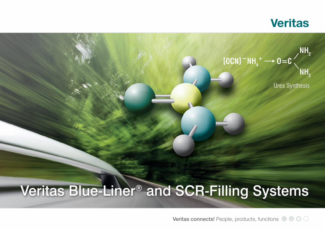
SCR = Selective Catalytic Reduction
1. The Basics of Selective Catalytic Reduction
In reaction to the consistently rising number of motor vehicles leading to higher traffic density – in particular in metropolitan areas – legislators are required to impose ever stricter exhaust-gas limit values for new vehicles. As the number of diesel-powered cars has risen dramatically over the past years, particularly in Europe, the distinct reduction of nitrogen oxide limits for diesel engines is the most noticeable challenge. Further tightening of the EU air-quality guidelines has also considerably enhanced require-ments on the automotive industry. These guidelines define the degree of contaminant concentration in the ambient air (immission) and the admissible particulate matter pollution. Considerably stricter nitrogen oxide limits have been in effect here since January 1, 2010.
As the enforcement and implementation of these legal requirements was no longer to be accomplished exclusively by optimizing combustion engines, automobile manufac-turers were compelled to find new solutions. They opted for a solution model which had already been routinely applied in power-plant boiler systems to reduce pollution levels – this method is known as »selective catalytic reduction« [SCR]. It enables a selective chemical reaction at the catalyst primarily supporting reduction of nitrogen oxides without any undesired side effects occurring. As the reducing agent for motor vehicles is fluid, the system for storing and dosing the agent in motor vehicles must be similar to that for fuel supply to the engine.
Introduction of the Euro-6 standard for passenger cars brought with it that develop-ment of SCR systems in this domain has been intensified and has in part already been
implemented in series manufacture. The greatest differences between truck and car systems are the more complex structure of the latter owing to narrow installation space in the vehicle itself and car drivers’ demands on service comfort. Further sophistica-tion of SCR systems is also driven in general by the fact that maximum emission levels are being lowered by the European Union and throughout the entire world. Relevant international legislature are the rules and regulations enforced by the EU, CARB, EPA and Japan (p. 7).
Reduction Process • ureasolutionisinjectedupstreamoftheSCR-catalyst • thereactionproducesammoniac • the produced ammoniac blends with the exhaust gas / flue gas in the catalyst
Hydrolysis: HNCO + H2O NH3 + CO2
Reduction: 4NH3 + 4NO + O2 4N2 + 6H2O 4NH3 + 6NO 5N2 + 6H2O 4NH3 + 2NO2 + O2 3N2 + 6H2O 8NH3 + 6NO2 7N2 + 12H2O
(at 200° - 400°C depending upon active component)

1.1 SCR Systems
Modern SCR systems such as those currently installed in diesel-fueled passenger cars operate on the basis of an aqueous urea solution being applied as reducing agent; such solution being known throughout the industry under the registered trade name AdBlue®. SCR systems may principally be structured into three function units: • thesystemconductingthechemicalsubstance • theexhaust-gastract • sensorsandcontrolsystem The detailed structure of the individual system units and of the entire SCR system is ultimately influenced and defined by the conditions particular to each vehicle. Fig. 1 shows the fundamental structure of an SCR system.
4 |
Fig. 1: SCR System
(1) AdBlue® tank(2) Heated in-tank pump(3) Filling-level sensor(4) Dosing line(5) Dosing valve(6) Tank filler neck(7) Conduit heater(8) Diesel particulate filter(9) Oxidation catalyst
Veritas Blue-Liner® and SCR-Filling Systems
(10) Dp sensor(11) Combustion engine(12) Mixer(13) SCR catalyst(14) Slip catalyst(15) Sensor/control lines(16) Dosing control unit(17) CAN-Bus(18) Onboard Diagnostics(19) Exhaust-gas tract

1.2 Liquid Conduit System
The liquid conduit system consists of an AdBlue® storage tank mounted, for example, in the spare-wheel well or the wheel case and with a filling capacity of between 10 and 35 liters, a bi-directional conveyor pump heated by the swirl pot, a filling-level sensor, a heated dosing line as well as the dosing valve integrated in the exhaust-gas tract. The storage tank is filled through the tank filler neck.
The tank inlet is located either in the trunk or in the fuel-tank pan next to the fuel tank filler neck. Special ventilation conduits and valves will compensate for pressure fluctuations in the system caused by changing temperatures, filling levels and driving conditions. This pressure compensation is required to make AdBlue® available as needed throughout all driving operations. The ventilation system is particularly impor-tant during storage-tank filling operations.
To be able to use the AdBlue® filling station infrastructure already available for trucks, the standard SCR system for cars is designed for a filling rate of up to 40 l per minute. To achieve this rate, the displaced air must at the same time be allowed to escape at the same rate.
1.3 Reduction Agent AdBlue®
Even if AdBlue® is the most commonly-used NOx reducing agent in Europe, it has a number of shortcomings as relates to its properties. These include the high freeze point of –11.5 °C, the tendency to form solid residues if evaporation is retarded or the relatively low share in active ammoniac as compared to alternative reducing agents. The essential chemico-physical properties of AdBlue® are:
• high-puritytransparentliquid • 32.5%ureaindemineralizedwater • density:1.09g/cm3
• freezepoint:–11.5°C(variationofvolume11%) • activeammoniaccontentpervolume:0.22kg/l • pH:10 • hightendencytocreep • crystallization • potentiallyunpleasantodors
The great advantage of AdBlue® as compared to other liquid ammoniac precur-sor substances is that AdBlue® is not classified as hazardous material and that it is entirely harmless in physiological terms. As relates to its water polluting risk, it is allocated to the lowest water hazard category (class 1).
The quality requirements on AdBlue® are specified in ISO 22241-1 and DIN 70070.
| 5

2. Emission Laws and Regulations
In the past years, there have essentially been four regulatory models in effect which are applied in various manifestations in all threshold and industry countries. CARB regulations > California; similar maximum levels apply in New York, Massachusetts, Connecticut, Vermont, Rhode Island, Maine, New Jersey EPA legislature (Environmental Protection Agency) > applies to all other US states EU legislature Japan legislature
The following chart shows the laws in effect throughout the entire world as well as the time of their enactment.
Tab.1:EmissionLawsandRegulations
2013 2014 2015 2016 2017 2018 2019 2020
Europe
CzechRepublic Euro5 Euro6
France Euro5 Euro6
Germany Euro5 Euro6
Hungary Euro5 Euro6
Italy Euro5 Euro6
Poland Euro5 Euro6
Russia Euro4 Euro5
Slovakia Euro5 Euro6
Turkey Euro5 Euro6
Great Britain Euro5 Euro6
China
Beijing Euro5
China Euro4 Euro5
Taiwan Euro5
Japan/Korea
Japan Japan´09
SouthKorea Euro5 Euro6
MiddleEast/Africa
Iran Euro 2
SouthAfrica Euro4
NorthAmerica
Canada TierII,Bin4 Tier II, Bin 2
Mexico(gasoline) Euro4 Euro5
USA TierII,Bin4 Tier II, Bin 2
USA(California) LEV III
SouthAmerica
Argentina Euro5
Brazil(LCVdiesel) Euro5 Euro6
Brazil(gasoline) Euro5 Euro6
SouthAsia
Australia Euro4
India(NewDelhiregion) Euro4
India(other) Euro 3
Indonesia Euro4
Malaysia Euro 3
Thailand Euro4
6 | Veritas Blue-Liner® and SCR-Filling Systems

speaking only non-polar substances consisting of pure hydrocarbon chains such as the elastomers EPDM or butyl rubber (IIR) or cross-linked thermoplastic elastomer (TPV) made of EPDM and/or butyl rubber with proper thermoplastics are suited as hard phase. Weakly polar rubbers such as hydrogenated acrylnitrile-butadiene rubber (H-NBR) with low acrylnitrile (ACN) content and TPE-S, e.g. block copolymers made of styrole and butadiene units are sufficiently/adequately resistant against permanent contact with urea solution.
In selecting materials, particular attention must be paid to the issue of ammoniac per-meability specifically in the light of dipolar as well as steric and structural interaction. Several EPDM as well as butyl rubber types feature high molecular weights, dense packings and as a consequence favorable permeation rates.
Chart.2:TotalPermeationofElastomericConduitMaterials(AdBlue®)
3. Material Specifications
The materials used to manufacture the components integrated in the SCR system must principally meet the following requirements: • chemicalstability · dipolar interaction · hydrolysis • temperaturestability:80°C/120°C • flexibilityatlowtemperatures:–40°C • purity(DIN70070) • NH3permeation • NH3 corrosion The chemical requirements are derived directly from the SCR system’s intended function. The component materials must be resistant against polar and alkaline urea solution (AdBlue®),theymaynotbesubjecttohydrolysisand/orbechemicallyinsta-ble and must also be able to withstand extreme ambient conditions over an extended period of time. Contamination of AdBlue® by any erosion material detached from the conduit material must be avoided, and permeation of ammoniac must be effectively prevented.
3.1Elastomers/AmorphousMaterials
Dipolar and steric interaction must be taken into consideration when selecting the material for SCR hose conduits, gaskets or membranes. A rule for dipolar interaction is that polar substances are soluble in polar solvents and the non-polar ones in non-polar solvents. Owing to the high dipole moment of the aqueous urea solution, strictly
Relativepermeationrate
EPDM H-NBR(21%ACN) AEM
6
5
4
3
2
1
0
| 7
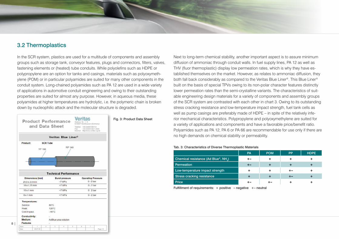
Next to long-term chemical stability, another important aspect is to assure minimum diffusion of ammoniac through conduit walls. In fuel supply lines, PA 12 as well as THV (fluor thermoplastic) display low permeation rates, which is why they have es-tablished themselves on the market. However, as relates to ammoniac diffusion, they both fall back considerably as compared to the Veritas Blue Liner®. This Blue Liner® built on the basis of special TPVs owing to its non-polar character features distinctly lower permeation rates than the semi-crystalline variants. The characteristics of suit-able engineering design materials for a variety of components and assembly groups of the SCR system are contrasted with each other in chart 3. Owing to its outstanding stress cracking resistance and low-temperature impact strength, fuel tank cells as well as pump casings are preferably made of HDPE – in spite of the relatively infe-rior mechanical characteristics. Polypropylene and polyoxymethylene are suited for a variety of applications and components and have a favorable price/benefit ratio. Polyamides such as PA 12, PA 6 or PA 66 are recommendable for use only if there are no high demands on chemical stability or permeability.
Tab.3:CharacteristicsofDiverseThermoplasticMaterials
PA POM PP HDPE
Chemicalresistance(AdBlue®, NH3) +– + + +
Permeation +– + + +
Low-temperatureimpactstrength + + +– +
Stresscrackingresistance + + +– +
Price +– +– + +
Fulfillmentofrequirements:+positive–negative+–neutral
3.2Thermoplastics
In the SCR system, plastics are used for a multitude of components and assembly groups such as storage tank, conveyor features, plugs and connectors, filters, valves, fastening elements or (heated) tube conduits. While polyolefins such as HDPE or polypropylene are an option for tanks and casings, materials such as polyoxymeth-ylene (POM) or in particular polyamides are suited for many other components in the conduit system. Long-chained polyamides such as PA 12 are used in a wide variety of applications in automotive conduit engineering and owing to their outstanding properties are suited for almost any purpose. However, in aqueous media, these polyamides at higher temperatures are hydrolytic, i.e. the polymeric chain is broken down by nucleophilic attack and the molecular structure is degraded. Fig.3:ProductDataSheet
8 |
4. Functional Structure of SCR Conduit Systems
The SCR conduit system usually consists of a filling and a venting tract. Both tracts not only differ in terms of their functions, but also in their dimensions and the installed components. The filler neck consists essentially of a filling head, a tube or hose and a connectorjoiningtheconduittothestoragetank.Aspit-backvalveisinstalledeitherinthe hose or tank. The vent conduit is composed of at least one ventilation valve, which asanalternativemayalsobeinstalledinthetank,atubeandalsoaconnectorjoiningthe conduit to the storage tank.
4.1FillerConduit
The process of refueling AdBlue® is defined by the interaction between all used com-ponents. Switching off the pump nozzle during the refueling process prior to reaching therequiredfillingvolume(»prematureshut-off«)mustjustasmuchbeavoidedasliquid splashing from the filler head owing to excessive internal pressure (spit-back).
The interior diameter of the filler conduit must be adequately dimensioned to assure the required flow rate is achieved in the filling process. This flow rate is conditional upon the diverse filling methods. While AdBlue® fueling with canisters or so-called Krusebottlehasnomajoreffects,fillingwithpumpnozzlerequiresprecisemonitoringof the flow rate owing to the diverse pump nozzle models in use. Focus is currently on achieving a maximum filling speed of 40l/min as is standard rate for filling trucks, but filling operations at lower feed rates must also be taken into consideration.
4.1.1FillingHead
The filling head of an SCR system has a variety of functions. There are filling heads for AdBlue® fueling from the outside, which enable the driver to autonomously replen-ish the AdBlue® storage tank with a pump nozzle, as well as other filling head variants for internal AdBlue® fueling, for example in the car trunk. However, these are suitable only for refilling with canisters or bottles. Refilling from the outside is the prevailing method.
Another factor to be considered in designing the filling head is venting. The storage-tank air displaced by the incoming AdBlue® can either be conducted through the vent line to the filling head or can be directly released to the outside, for example to the wheel case.
Thefillingheadcomponentsaswellasitsmajorfunctionsareexplainedinthefollow-ing text.
| 9

Fig.4:FillingHead
Filling Head Port
The interior diameter of the filling head port must be adapted to accommodate the di-verse pump nozzles used to dispense AdBlue®. The outside diameter usually features an exterior thread suited both for screwing on an adapter for canister replenishment and for screwing on an AdBlue® bottle (e.g. Kruse bottle). Those systems passing on to the environment the air displaced during the filling process usually have an internal contour with grooves allowing the emissive air to escape.
Magnet
The front section of the filling head features a magnet which is designated to trigger the opening mechanism in the pump nozzle. The intent is to prevent operators from refilling the wrong liquid and to avoid any premature activation of the pump nozzle. The pumping process can be triggered only after the pump nozzle is in its correct position. 80% of the pump nozzles in use across Europe have magnet-triggered release mechanisms, while most of the pump nozzles used in the USA can also be activated without magnet.
InteriorAdapterElementinFillerHead
The filler head in numerous applications will feature an adapter element into which the pump nozzle tip is inserted. This adapter element is designated to accommodate manufacturers’ various designs of pump nozzles to assure that liquid streams par-ticular to these various designs will not clog the filler neck thereby triggering prema-ture pump nozzle shut-off. Another purpose of this adapter element is to separate the AdBlue® streaming in from the escaping air. It prevents the AdBlue® from being caught in the escaping air and discharging from the filler head port towards the indi-vidual filling the tank.
A wash element designated to prevent spit-back of AdBlue® during the refilling pro-cess is located in the lower section of the adapter element facing the filler neck. Fin structures in the adapter element stabilize the direction of flow and provide centering aid and limit stop for the pump nozzle. This limit stop is important for holding the pump nozzle in the proper position, an essential condition for activating the magnet’s triggering function.
10 | Veritas Blue-Liner® and SCR-Filling Systems

Fig.5:FillingHead
FillerHeadCasing(upperandlowerpart)
The filler head casing is frequently designed as two or three-part assembly unit to be able to integrate all elements stated above. The casing is also designed to allow at-tachment of the filler head to the car body, which may be accomplished either by di-rect fastening or with an additional bracket. The type of attachment chosen depends essentially on the available installation space and the sequence of assembly.
The specified filler head size (volume) should be adequately dimensioned to accom-modatespit-backandfill-to-maxquantities.Theareajoiningthefillerheadandthefiller neck must be designed in accordance with rheological considerations to avoid any backlog in the filling process.
4.1.2TubeComponent
The need for a relatively large interior diameter for the tube or hose conduit frequently causes problems with conduit routing. Collisions are almost inevitable, as there is usually only little installation space available and small bending radii cannot be ac-complished with large conduit diameters. On the other side, ease of handling and conduit flexibility in assembly are high-priority requirements in particular for uncom-plicated installation at car assembly plants. To achieve this flexibility, the conduits in some applications are equipped with additional components such as corrugated pipes or hoses. In particular the connection to the storage tank is frequently fitted with a particularly flexible element, on one side in order to assure proper connection of the filling conduit to the AdBlue® tank in the vehicle, on the other to compensate for in-stallation and manufacturing tolerances of the diverse component parts. Furthermore, in the event of an accident leading to car-body deformation, separation of the filling conduit from the storage tank may to some extent be prevented.
4.1.3Spit-backValve
After the refilling process has been completed, the tank might discharge excessive interior pressure through the filling tube. Flap valves also called spit-back valves are installed to prevent any liquid from spilling from the tube. This spit-back valve con-sists of a spring-mounted flap which closes the diameter of the filling tube to prevent any spit-back.
Filler Conduit WashElement Magnet AdapterElement
Ventilation Conduit
| 11
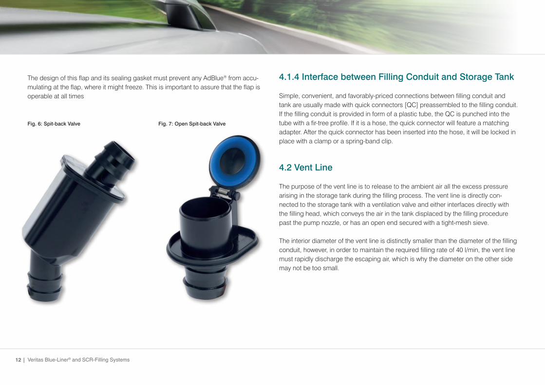
The design of this flap and its sealing gasket must prevent any AdBlue® from accu-mulating at the flap, where it might freeze. This is important to assure that the flap is operable at all times
Fig.6:Spit-backValve Fig.7:OpenSpit-backValve
4.1.4InterfacebetweenFillingConduitandStorageTank
Simple, convenient, and favorably-priced connections between filling conduit and tank are usually made with quick connectors [QC] preassembled to the filling conduit. If the filling conduit is provided in form of a plastic tube, the QC is punched into the tube with a fir-tree profile. If it is a hose, the quick connector will feature a matching adapter. After the quick connector has been inserted into the hose, it will be locked in place with a clamp or a spring-band clip.
4.2VentLine
The purpose of the vent line is to release to the ambient air all the excess pressure arising in the storage tank during the filling process. The vent line is directly con- nected to the storage tank with a ventilation valve and either interfaces directly with the filling head, which conveys the air in the tank displaced by the filling procedure past the pump nozzle, or has an open end secured with a tight-mesh sieve.
The interior diameter of the vent line is distinctly smaller than the diameter of the filling conduit, however, in order to maintain the required filling rate of 40 l/min, the vent line must rapidly discharge the escaping air, which is why the diameter on the other side may not be too small.
12 | Veritas Blue-Liner® and SCR-Filling Systems

4.2.1VentValve
Quantity, position and type of valves depends strongly upon the design of the entire SCR System. In a standard passenger car, the filler head port is usually found at the highest-possible position in the wheel housing. As a consequence, the ventilation line port is lower than the filler head and liquid might escape. The float valve is installed to prevent exactly this from occurring. A float valve will rise upwards to close the dis-charge port of the ventilation line.
The advantage of this system is that the air outlet port is positioned behind the car-body panels and that operators will not experience any unpleasant odors. It is essential that float valves must have minimum surface contact to prevent them from freezing. The valve‘s function must be assured at all driving angles, in particular in SUVs, and the valve must be designed to be elastic and reliable even at –40°C.
Fig.8:VentValve
Another strategy to keep the liquid rising in the ventilation line from escaping is to in-stall a vent surge tank with sufficient capacity to accommodate the liquid volume and to position it between filler head and storage tank. However, an essential requirement here is that there is sufficient installation space available.
StandardDrivingOperations
In standard driving operations, a motor vehicle will consume approx. 1 l AdBlue® per 1,000 kms (reference rate). Tank ventilation through vent valves and/or diaphragm must be provided here to allow the AdBlue® consumed in normal driving operations to be replaced by air. An open system cannot be installed owing to the risk of crystal-lization. (see fig. 8).
| 13

5. Tests
In the development phase, extensive tests of the SCR system are conducted to verify the function of all components throughout the entire life cycle. Service life tests simulate the life cycle of complete component groups in time-lapse mode. The requirements are based on legal provisions and customer specifications (company standards and customer requirements sheets). The loads usually applied in varying combinations are temperature variation, pressure fluctuations, and vibration stimula-tion.
5.1VeritasAGTestFacilities
TemperingTests/Long-termSoaking • 9temperingcabinetsofvarioussizesavailable • effectivetemperaturerangebetween-80°Cand+180°C
ExcessPressure/NegativePressure • pulsationunitforlong-termtests • optionalcombinationwithtemperingcabinets
Burst Pressure • burst pressure test installation for proving diverse materials and temperatures
VibrationTests • 3shakertestbenches • equippedforendurancetests
Multi-axleExcitation • Hexapodtestbenchformotionsimulation
Fueling • 2fuelingstationsforexaminingfuelingconduct • facilitiesfortestingallcomponents(spit-back,valvefunctions,…)alsoin extreme temperature environment
Slosh • sloshtestbench • velocityandretardationmaybeadjustedtomeetrequirements; integrated drive for endurance tests
DimensionalInspection • severalmeasuringdeviceswithscannersand/ortactilemeasuringfeature
Material Tests • VeritasAGiscapableofconductingallmaterialanalyses (mechanical characteristics and analytics)
Fig. 9: Tempering cabinet
Fig. 12: CT-unit
Fig. 10: Fueling station
Fig. 13: Driving profile simulation on Hexapod
Fig. 11: Slosh Tester endurance test
Fig. 14: Vibration test on shaker
14 | Veritas Blue-Liner® and SCR-Filling Systems
6. A look ahead
The requirements on environmental protection lead to consistently stricter legislature, which – in addition to reduction of CO2 emissions and thus reduction of fuel con-sumption itself – is designed to decrease the emissions of any pollutants whatsoever. This also includes particulate matter and nitrogen oxides (NOx). The latter may be reduced in conventional combustion engines for example by installing SCR systems.
Contemporary passenger-car propulsion is almost entirely based on combustion engines. Even though in the past years there has been in fact quite some progress made as relates to the development of alternative propulsion systems such as hybrid concepts, battery-operated electric power trains, fuel cells or hydrogen-powered engines – economical, comfortable (range!) and thus marketable solutions will not be available for a number of years to come. Even state-of-the-art hybrid cars in the fore-seeable future will not be able to travel without combustion chambers using oil-based fuel.
Theimportantshortandmid-termobjectivesforcontemporarySCRsystemsareinstallation not only in diesel engines but in gasoline engines as well as simplification of SCR system in order to reduce costs and easier handling of reducing agents. Per-haps the aqueous urea solution currently in use might at some later date be replaced by solid-material products. However, it will certainly be a long time before that is in anywayfeasible,ashandlingsuchsolidmaterialisstillamajortechnicalchallengeon engineers.
Inconjunctionwithanexhaustgasrecirculationsystem(EGR),whichdecreasestem-peratures already in the combustion chamber and thereby reduces the formation of nitrogen oxides, the SCR system is the first-line approach to continue putting environ-mentally compatible cars with combustion engines on the market in the future as well.
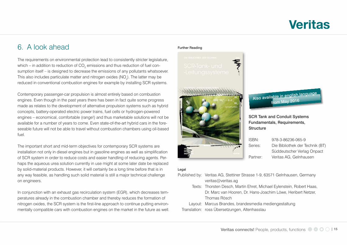
FurtherReading
SCRTankandConduitSystemsFundamentals, Requirements, Structure
ISBN: 978-3-86236-065-9Series: Die Bibliothek der Technik (BT) Süddeutscher Verlag OnpactPartner: Veritas AG, Gelnhausen
Legal
Published by: Veritas AG, Stettiner Strasse 1-9, 63571 Gelnhausen, Germany [email protected] Texts: Thorsten Desch, Martin Ehret, Michael Eylenstein, Robert Haas, Dr. Marc van Hooren, Dr. Hans-Joachim Löwe, Heribert Netzer, Thomas Rösch Layout: Marcus Brandes, brandesmedia mediengestaltung Translation: ross Übersetzungen, Altenhasslau
| 15
Alsoavailableinenglishlangua
ge
fromMay2016

Veritas - always striving to find innovative solutions for protecting the environment, meeting legal requirements,
and further improving automotive functions – all over the world.