Verification and Inference of Positions in Vehicular...
14
1 Verification and Inference of Positions in Vehicular Networks through Anonymous Beaconing Francesco Malandrino, Member, IEEE, Carlo Borgiattino, Student Member, IEEE Claudio Casetti, Member, IEEE, Carla-Fabiana Chiasserini, Senior Member, IEEE, Marco Fiore, Member, IEEE, and Roberto Sadao, Student Member, IEEE ✦ Abstract—A number of vehicular networking applications require continuous knowledge of the location of vehicles and tracking of the routes they follow, including, e.g., real-time traffic monitoring, e-tolling, and liability attribution in case of accidents. Locating and tracking vehicles has however strong implications in terms of security and user privacy. On the one hand, there should be a mean for an authority to verify the correctness of positioning information announced by a vehicle, so as to identify potentially misbehaving cars. On the other, public disclosure of identity and position of drivers should be avoided, so as not to jeopardize user privacy. In this paper, we address such is- sues by introducing A-VIP, a secure, privacy-preserving framework for continuous tracking of vehicles. A-VIP leverages anonymous position beacons from vehicles, and the cooperation of nearby cars collecting and reporting the beacons they hear. Such information allows a location authority to verify the positions announced by vehicles, or to infer the actual ones if needed, without resorting to computationally expensive asymmetric cryptography. We assess the effectiveness of A-VIP via realistic simulation and experimental testbeds. Index Terms—Vehicular networks, position verification, privacy. 1 I NTRODUCTION Borrowing from a well-established communication pattern in wireless LANs, vehicular networks have adopted the term beaconing to indicate the periodic broadcasting of messages to neighboring vehicles or road-side units (RSUs). These messages, defined, e.g., in the SAE J2735 specifications, can be used for safety purposes as well as for coopera- tive awareness. The information they carry (e.g., vehicle ID, timestamps and location information) may be secured through the use of an on-board tamper-proof Hardware Security Module (HSM) as well as signatures, cryptography and certificates [1]. Secure beacons for vehicle position identification and tracking are needed in a number of scenarios where vehicle position accountability is a requirement in order to provide F. Malandrino, C. Borgiattino, C. Casetti and C.-F. Chiasserini are with Politecnico di Torino, Torino, Italy. M. Fiore is with CNR–IEIIT, Torino, Italy and INRIA, Lyon, France. R. Sadao is with Universidade de São Paulo, São Carlos, Brazil. services to the community or to drivers. Secure reporting of vehicle location can substantiate drivers’ claims in case of accidents. At the same time, secure location verification by authorities can provide accountability for those involved. However, ensuring secure positioning must cope with three major problems, concerning (i) users’ privacy, (ii) computational costs of security and (iii) the system trust on user correctness. As for the first aspect, when not strictly required, public disclosure of the vehicle identity to all receiving devices in the proximity of a beaconer is an issue. Vehicles can be tracked, jeopardizing drivers’ privacy and requiring complex pseudonym management [2]. Thus, there is a need for separating secure position identification by authorities and the possibility of undesirable user tracking by peers in the vehicular network. As for the second aspect, standard security mechanisms based on, e.g., asymmetric cryptography, induce significant protocol overhead and com- putational complexity. In fact, their use is recommended to be largely dependent on the applications and circumstances, and avoided whenever possible [3]. Finally, basic solutions cannot guarantee the correctness of the location information provided by a user who owns the required cryptographic material, but has a malfunctioning GPS receiver or can tamper with GPS data before they are input to the HSM. In this paper, we address the issues above by proposing A-VIP (Anonymous Verification and Inference of Positions), a framework that, unlike previous work: (i) allows a trusted authority to securely collect and verify the positions claimed by vehicles without resorting to computationally expensive asymmetric cryptography – as is instead done in the IEEE 1609.2 standard [4]; (ii) in presence of unverified location claims, grants the authority the capability to infer the actual position of mal- functioning or misbehaving vehicles; (iii) does so by safeguarding drivers’ privacy with respect to other vehicles participating in the network, and without any requirement for uninterrupted radio coverage from road- side infrastructure.
-
Upload
phungtuong -
Category
Documents
-
view
215 -
download
0
Transcript of Verification and Inference of Positions in Vehicular...

1
Verification and Inference ofPositions in Vehicular Networksthrough Anonymous Beaconing
Francesco Malandrino, Member, IEEE, Carlo Borgiattino, Student Member, IEEE Claudio
Casetti, Member, IEEE, Carla-Fabiana Chiasserini, Senior Member, IEEE, Marco Fiore, Member, IEEE,
and Roberto Sadao, Student Member, IEEE
✦
Abstract—A number of vehicular networking applications require
continuous knowledge of the location of vehicles and tracking of the
routes they follow, including, e.g., real-time traffic monitoring, e-tolling,
and liability attribution in case of accidents. Locating and tracking
vehicles has however strong implications in terms of security and user
privacy. On the one hand, there should be a mean for an authority
to verify the correctness of positioning information announced by a
vehicle, so as to identify potentially misbehaving cars. On the other,
public disclosure of identity and position of drivers should be avoided,
so as not to jeopardize user privacy. In this paper, we address such is-
sues by introducing A-VIP, a secure, privacy-preserving framework for
continuous tracking of vehicles. A-VIP leverages anonymous position
beacons from vehicles, and the cooperation of nearby cars collecting
and reporting the beacons they hear. Such information allows a
location authority to verify the positions announced by vehicles, or
to infer the actual ones if needed, without resorting to computationally
expensive asymmetric cryptography. We assess the effectiveness of
A-VIP via realistic simulation and experimental testbeds.
Index Terms—Vehicular networks, position verification, privacy.
1 INTRODUCTION
Borrowing from a well-established communication patternin wireless LANs, vehicular networks have adopted the termbeaconing to indicate the periodic broadcasting of messagesto neighboring vehicles or road-side units (RSUs). Thesemessages, defined, e.g., in the SAE J2735 specifications,can be used for safety purposes as well as for coopera-tive awareness. The information they carry (e.g., vehicleID, timestamps and location information) may be securedthrough the use of an on-board tamper-proof HardwareSecurity Module (HSM) as well as signatures, cryptographyand certificates [1].
Secure beacons for vehicle position identification andtracking are needed in a number of scenarios where vehicleposition accountability is a requirement in order to provide
F. Malandrino, C. Borgiattino, C. Casetti and C.-F. Chiasserini are with
Politecnico di Torino, Torino, Italy.
M. Fiore is with CNR–IEIIT, Torino, Italy and INRIA, Lyon, France.
R. Sadao is with Universidade de São Paulo, São Carlos, Brazil.
services to the community or to drivers. Secure reporting ofvehicle location can substantiate drivers’ claims in case ofaccidents. At the same time, secure location verification byauthorities can provide accountability for those involved.
However, ensuring secure positioning must cope withthree major problems, concerning (i) users’ privacy, (ii)computational costs of security and (iii) the system trust onuser correctness. As for the first aspect, when not strictlyrequired, public disclosure of the vehicle identity to allreceiving devices in the proximity of a beaconer is an issue.Vehicles can be tracked, jeopardizing drivers’ privacy andrequiring complex pseudonym management [2]. Thus, thereis a need for separating secure position identification byauthorities and the possibility of undesirable user trackingby peers in the vehicular network. As for the second aspect,standard security mechanisms based on, e.g., asymmetriccryptography, induce significant protocol overhead and com-putational complexity. In fact, their use is recommended tobe largely dependent on the applications and circumstances,and avoided whenever possible [3]. Finally, basic solutionscannot guarantee the correctness of the location informationprovided by a user who owns the required cryptographicmaterial, but has a malfunctioning GPS receiver or cantamper with GPS data before they are input to the HSM.
In this paper, we address the issues above by proposingA-VIP (Anonymous Verification and Inference of Positions),a framework that, unlike previous work:
(i) allows a trusted authority to securely collect andverify the positions claimed by vehicles without resortingto computationally expensive asymmetric cryptography – asis instead done in the IEEE 1609.2 standard [4];
(ii) in presence of unverified location claims, grants theauthority the capability to infer the actual position of mal-functioning or misbehaving vehicles;
(iii) does so by safeguarding drivers’ privacy with respectto other vehicles participating in the network, and withoutany requirement for uninterrupted radio coverage from road-side infrastructure.

2
To achieve such goals, A-VIP leverages anonymous posi-
tion beacons from vehicles, which prevent overhearing nodesfrom identifying or tracking their source, but still allowauthorized third parties – sharing secret information withthe beaconing vehicles – to perform such operations. Then,an authenticated reciprocal beacon reporting scheme grantsan authority the possibility to verify the locations claimed byvehicles and infer unverified positions by efficiently solvingan optimization problem.
The rest of the paper is organized as follows. Afterreviewing related work in Sec. 2, we describe the systemscenario and communication protocol in Sec. 3. Sec. 4details the location verification and inference procedures,while Sec. 5 discusses the resilience of A-VIP to attacksby adversarial vehicles. The performance of A-VIP in bothsimulated and real-road environments is shown in Sec. 6.Finally, Sec. 7 concludes the paper.
2 RELATED WORK
When considering the problem of location verification andinference, an extensive literature can be found in the domainof wireless sensor networks, including among others [5]–[8]. However, it is commonly acknowledged that solutionsdesigned for static nodes do not fit the highly mobilevehicular scenarios we target.
Specific to the vehicular environment, many works havefocused on pure ad-hoc vehicular network environmentswhere no infrastructure or central authorities are considered.There, the aim is the verification of reciprocal positioninformation so as to secure cooperative awareness and mul-tihop routing. To that end, a number of different solutionshave been proposed that leverage diverse metrics, includingthe distance among nodes and their relative mobility [9],[10], the Time-of-Flight (ToF) distance bounding [11] andranging [12], the Received Signal Strength (RSS) within atwo-hop neighborhood [13], or the presence of Non Line-of-sight (NLOS) conditions [14]. There have also been propos-als to use dedicated hardware, such as multiple directionalantennas [15], or original data structures, such as trustedrouting tables [16].
With A-VIP, we take a different approach, considering theproblem of vehicle position verification from the viewpointof a trusted authority that collects car-generated locationinformation through a roadside or cellular infrastructure.To the best of our knowledge, ours is the first attempt atdesigning a position verification system that considers sucha perspective – which, although less visionary than the ad-hoc one, is more consistent with that expected to be the mostviable architecture for secure vehicular communication sys-tems [17]. Thus, our optimization problem formulation andthe resulting centralized solution are hardly comparable withthe techniques presented in the papers mentioned before.
We also remark that A-VIP does not only allow for posi-tion verification, but also addresses the problem of inferringthe location of untrusted cars, and does so by granting useranonymity. Solutions have been proposed that specifically
tackle the latter problems individually, such as [18], [19], butours is the first work to present a comprehensive frameworkfor secure, privacy-preserving localization.
Finally, our work is the first to experimentally evaluate theperformance of a position verification and inference systemthrough real-world testbeds.
3 ANONYMOUS POSITIONING PROCEDURE
We consider a WAVE-based vehicular network composed ofvehicles communicating with each other and, occasionally,with RSUs. No assumption is made on the deployment ofRSUs, so vehicles may travel along road segments where noRSU coverage is available. Vehicles may have also a 3G/LTEradio interface, through which they can access the cellularnetwork that fully covers the road topology. Both RSUs andcellular base stations allow vehicles to contact a LocationAuthority (LA), which is in charge of collecting locationclaims, verifying them and inferring the actual positions ofvehicles deemed to announce incorrect locations.
Vehicles are equipped with GPS, thus, unless otherwisespecified, they know their own position and share a commontime reference. Each vehicle owns cryptographic material,i.e., a certified identity and a long-term secret key, used toestablish a secure channel with the LA at any time, througheither an RSU or the cellular infrastructure. Solutions alreadyexist for the distribution and management of long-termpairwise keys in vehicular environments (see, e.g., [4], [17]),and their discussion is out of the scope of this paper.
Vehicles that comply with the A-VIP mechanism aredefined as correct, while the others may be: (i) faulty, thatis, they follow the protocol but provide incorrect informationdue to, e.g., GPS malfunctioning, or (ii) adversarial, i.e.,their aim is to announce a fake position and have it verified,so as to obtain some advantage, discredit nearby users, ordisrupt the A-VIP operation. To that end, adversarial nodescan either deviate from the A-VIP communication protocolprocedure, or comply with it but inject false information. Inthis work, we consider internal adversaries, more challengingthan external ones, as they own the cryptographic materialto participate in the protocol. We consider however thatadversaries are unable to forge messages on behalf of othernodes whose keys they do not have. Adversaries may befurther distinguished as independent or colluding: in thispaper we focus on the former. However, in our analysis wealso evaluate Sybil attacks, which can be viewed as a worstcase of an attack carried out by colluding adversaries.
3.1 A-VIP goals
A-VIP aims at verifying the positions announced by correctvehicles while guaranteeing their privacy with respect to theother ones, and at detecting faulty or adversarial nodes whileinferring their actual locations. Such goals are to be achievedwith low computational complexity.
We stress that, barring the use of complex pseudonymmanagement schemes [2], anonymity cannot be imple-mented simply by letting a vehicle issue beacons where its

3
iri oi
zn−1i
AES AES
......
vk
1
v i
v X1
n
Xi
n
......
Xk
n
Reporter vj
l j1
l ji
l jk
ln
i
ln
i
j1
LA
BeaconXn l
nii
ctr positionn
iK
n+1
n
n−1
......
precomputed secrets
t ji
j1t
t jk
X1n
Xin
Xkn
...
...
... ...
... ...
time position beacon Q
li
n n
...
...
Q
ji
jkQ
Q
n
nBeaconer v
Fig. 1. A-VIP procedures by beaconer, reporter and LA.
identity is encrypted with the long-term shared key it shareswith the LA. Indeed, some form of plaintext ID, attachedto the encrypted beacon, would be needed for the LA torecognize the beacon originator and choose the appropriatekey to decrypt the remainder of the message. Clearly, thepresence of a plaintext ID would jeopardize the vehicleprivacy, whose protection is one of our goals, allowing foroverhearing and tracking by unauthorized receivers.
Additionally, we cannot just rely on encrypted cellularupload of the positioning information by vehicles. As amatter of fact, A-VIP is designed to be compatible with thecellular access infrastructure, but not to depend on it. Moreimportantly, as discussed in Sec. 1, direct cellular uploaddoes not allow for a verification of the location claimed byvehicles, which is instead part of the goals of A-VIP.
3.2 Communication procedures
The procedures in the A-VIP protocol are described below,while a schematic overview is shown in Fig. 1.Registration. The registration procedure takes place everytime a vehicle is started, and is repeated after a registrationvalidity time has expired. It is performed over the securechannel between the vehicle and the LA, established withthe long-term key via the RSU infrastructure, if available,or through 3G/LTE, otherwise.
Let us assume that a generic vehicle vi sends a registrationrequest at time instant ti,0. The LA records such an instantand returns to the vehicle a registration triplet (Ki, ri, oi)where Ki is a short-term 128-bit AES symmetric key, andri, oi are random integers. The triplet is used to computea time-dependent secret xi(t), shared between the vehicleand the LA. As detailed later, when sent by vi to the LA,xi(t) allows the LA to verify the freshness of a beacontransmission and the identity of its originator. In order tocompute it, the two entities initialize a counter to ri andincrement it by oi every τb seconds, e.g., at every beacontransmission. The updated counter is then encrypted withKi using AES in counter mode (AES-CTR) [20]. Thus, ingeneral, if ti,0 + nτb ≤ t < ti,0 + (n + 1)τb, then xi(t) =EKi{ri+noi} = x
ni . Note that both ri and oi can be picked
at random since the chances of collision among x
n values,related to different vehicles at the same time, are negligible.
The LA is then in a position to precompute all theupcoming values of x
ni for a period that depends on the
registration validity time. Clearly, the amount of memoryneeded by the LA to store precomputed values of x
ni
depends on the average number of vehicles in the area servedby the LA and the time interval for which the x
ni values are
precomputed. As an example, in the scenario described inSec. 6.1 and assuming a validity time equal to 1 hour, therequired storage space at the LA for all vehicles amounts toan easily accommodated 52 Mbytes of memory.Anonymous beaconing. When traveling, all correct vehi-cles broadcast a beacon every τb, as foreseen by currentstandards. Beacon messages are broadcast by nature, andthus they are subject to undetected collisions over thewireless medium. While this may affect A-VIP operations,we stress that our approach can easily incorporate solutionsto dynamically reduce channel contention such as [21].For the purposes of this paper, we assume that all beacontransmissions occur at a power level common to all correctvehicles and at the basic data rate. Also, we assume thebeacon to be split into two parts: an encrypted one, forthe purposes set forth in this paper, and an unencryptedone, where plaintext content can be broadcast for suchpurposes as collision avoidance or cooperative awareness.We assume however that the beacon is anonymous, i.e., itdoes not include the vehicle identifier and it uses a freshrandom MAC-layer address [17]. When not transmitting,the vehicle listens to the channel, overhearing beacons fromother vehicles and collecting the information therein for laterreporting to the LA.
The beacon content is assembled using the triplet assignedto a vehicle during the registration. Specifically, the n-th beacon issued by a vehicle vi carries two pieces ofinformation, as shown in the “Beaconer” box of Fig. 1:
(a) the time-dependent secret xni , which can be computed
by vi and by the LA, independently of each other;(b) the encrypted current location announced by the
vehicle l
ni = EKi
{( lni || zn−1i ) ⊕ (ri + noi)}, computed
using the short-term pairwise key Ki from the triplet. Theplaintext location lni is concatenated with the one-bit flagzn−1i used to notify the LA whether the beacon issued at
step n− 1 was affected by a replay attack (as explained inSec. 5). Such a string is then XOR’ed with the plaintextcounter value (ri + noi), to ensure freshness of the beaconpositioning content and thwart partial-replay attacks (as alsodetailed in Sec. 5).Reporting. When a beacon issued by a vehicle vi is correctlyreceived by a vehicle vj , the latter is required to store thefollowing entry in a report table, such as the one depictedin the “Reporter” box of Fig. 1:
• the time tji at which the beacon is received;• its own position lji at the time the beacon was received;• the secret xn
i carried in the beacon;• the encrypted position l
ni of vi carried in the beacon;

4
• an optional field Qnji, indicating the received signal
quality (e.g., the received signal power computed bythe radio interface driver).
Every τr seconds (report interval), vj generates a report
message including the report table, populated with datacollected from all newly overheard beacons. The report istransmitted to the LA, ensuring authentication and integritythrough standard procedures. The transmission may occurvia the RSU or via the cellular network if RSUs are scarceand real-time positioning is required. Additionally, multihopvehicle-to-vehicle communication can be exploited to reachnearby RSUs and, hence, speed up the report delivery.
We remark that vehicles normally act as both beaconersand reporters, and that the LA needs to receive only reportmessages, not the beacons broadcast by vehicles. Also, thecommunication procedures outlined above allow for a fullyanonymous information exchange, preventing overhearingand thus ensuring user privacy.
4 POSITION VERIFICATION AND INFERENCE
When the LA receives reports from vehicles, it processesthem so as to (i) determine the locations announced by carsin the system, (ii) verify such locations and (iii) infer theactual positions of vehicles deemed to have advertised anincorrect location.
Let the LA divide the road topology into discretizedspatial tiles, whose set is denoted by S. Also, let V be theset of vehicles that the LA has to verify. Upon receiving areport message from vehicle vj ∈ V , the LA processes onereport table entry at a time, as follows:
• it extracts the time tji at which vj received the beacon;• for each vk ∈ V , it computes n such that tk,0 + nτb ≤
tji < tk,0+(n+1)τb, i.e., n = ⌊(tji− tk,0)/τb⌋, and itlooks up the precomputed secret value x
nk that matches
the x
ni in the report table entry (LA box in Fig. 1).
When a match is found, the LA identifies vi as the vehiclethat sent the beacon and retrieves the triplet associated toit 1. Then, the LA performs the following actions:
(1) it decrypts the l
ni field entered by vi in the beacon
reported by vj , extracting the announced position lni and theflag zn−1
i ;(2) if the zn−1
i flag is set, it discards the entry;(3) otherwise, if zn−1
i is unset, it stores n, the position lniincluded in the beacon by vi and the position lnj announcedby vj in the report table entry. If present, the LA also storesthe signal quality indicator, Qn
ji, that vj measured on thebeacon received from vi.
The LA leverages the information extracted from thereport table entry to identify the possible tiles correspondingto a vehicle position, thus verifying the location claim andpossibly determining the actual vehicle location in case ofmismatch. Clearly, the same beacon, characterized by asingle x
ni , may be reported by multiple vehicles traveling in
1. If no match for xni is found, the report entry is discarded. This may
happen as a result of, e.g., replay attacks or node malfunctioning.
vi
vjvk
(a)
vi
vjvk
(b)
Fig. 2. Q-unaware approach: vi’s beacon is reported tothe LA by vk and vj . The shaded circle in (a) represents
the transmission range of vi, while the white circles
denote the receiving range of vk and vj . The shadedarea in (b) represents the possible locations resulting
from the combination of the two reports.
the proximity of vi when the latter broadcasted it. If so, theLA can obtain a better estimation of the beaconer positionby combining the received reports. The steps required by thisoperation are detailed in the rest of this section, where, forsake of clarity, we drop the time notation and assume thatall measures refer to the same beacon broadcast interval n.
4.1 Cooperative position identification
Depending on whether the quality indicator Qji is includedin the report or not, the LA can adopt two different ap-proaches to identify the tiles corresponding to the positionof the beaconer vi. The two techniques, named Q-unawareand Q-aware, operate as follows.
The Q-unaware approach. In this case, the LA doesnot have any information on the quality level with whichthe beacon signal was received at the reporter. Thus, foreach pair of tiles (s, t) ∈ S2, it can assume a simple 0-1propagation model to state whether a beacon sent from tiles can be heard in t or not, i.e., h(s, t) : S2 → {0, 1}. Weremark that any methodology could be used to determinethe vehicle radio range: from a simple unit disc model,displayed in Fig. 2, to a signal map drawn from real-worldmeasurements [22].
Given that vj located in tile t ∈ S received the beacon
from vi, then the LA can identify a set of tiles, S(j)i ⊆ S,where the beaconer could have been. Due to the simplepropagation model, all tiles in S(j)i correspond to the rightlocation with equal probability. Thus, the probability that thebeaconer was in tile s when vj heard its beacon is given by:
p(j)i,s =
{
1
|S(j)i
|if s ∈ S(j)i
0 otherwise .(1)
Note that, if multiple reports from correct nodes areavailable, the corresponding sets of tiles may intersect, asdepicted in Fig. 2(b). In this case, the LA can obtain a betterestimate of the true position of vi. Considering the intersec-tion translates into computing the following probability:
P(Ri)i,s =
∏
j:vj∈Rip(j)i,s
∑
u∈S
∏
j:vj∈Rip(j)i,u
∀s ∈ S , (2)

5
vi
vjvk
(a)
vi
vjvk
(b)
Fig. 3. Q-aware approach: the beacon from vi is re-ported by vk and vj . The shaded area in (a) represents
the transmission range of vi. The annuluses denote the
set of locations from which a beacon could be receivedby, respectively, vk and vj with the quality level indicated
in their report. In (b), the intersection of the annulusesrepresents the possible positions of vi.
where Ri is the set of vehicles that reported vi’s beacon.We stress that p
(j)i,s represents the probability that vi was
in s while sending the beacon, computed taking only onereport into account. P (Ri)
i,s represents the same probability,yet computed by combining the information received frommultiple correct reporters.
The Q-aware approach. When a report includes the Qji
value related to a beacon reception, such information can beexploited to refine the position estimate of beaconer vi. Todo so, the LA needs an accurate model of the propagationconditions in the area where the broadcast transmission tookplace, including received signal quality information. Again,deterministic (e.g., ray-tracing), stochastic, or measurement-based models can be used: the Q-aware procedure does notchange and is performed as follows.
Let the propagation model be a function h(s, t, Qji) :S2×R→ [0, 1] that, for any pair of tiles (s, t) and any signalquality value Qji, provides the probability P(R
(j)t |B
(i)s , Qji)
that a beacon sent by vi from tile s can be received byvj ∈ Ri in tile t, with the quality level Qji reported by vj .
By applying Bayes’ theorem, the LA can use such valuesto compute the probability P(B
(i)s |R
(j)t , Qji) that the bea-
coner was in title s, given that the beacon was heard by vjin tile t, with a quality level Qji. Specifically,
p(j)i,s = P(B(i)
s |R(j)t , Qji) =
=P(R
(j)t |B
(i)s , Qji) · P(B
(i)s )
∑
u∈S P(R(j)t |B
(i)u , Qji) · P(B
(i)u )
(3)
where P(B(i)x ), x = s, u, is the probability that the broad-
casting vehicle vi is in tile x at the time of transmission. Thisvalue may depend on the vehicle density and on the size ofthe considered area. We assume however a generic scenariowhere no such knowledge is available, and the probabilityis equally spread among all tiles, i.e., P(B(i)
s ) = 1/|S| forany vi and any tile in s ∈ S.
Upon receiving multiple reports, the LA can again resortto (2) to combine the Q-aware probabilities computed as in(3). Then, it can determine the tiles the beaconer could have
been at the moment of the broadcast, with the associatedprobabilities P
(Ri)i,s . Note that, unlike the Q-unaware case,
such probabilities are now Q-dependent and provide betterlocation estimates, assuming that the underlying signal qual-ity model is accurate enough.
A simple example of the Q-aware approach is portrayedin Fig. 3, where two reporters, vk and vj , include differentquality levels for a beacon received from vi. For simplicity,in the figure we considered that the area corresponding tothe value of Q, indicated by a reporter, maps onto an annuluscomprised in its reception range. Then, the set of possiblelocations of the beaconer is given by the intersection of thetwo annuluses, i.e., the shaded area in Fig. 3(b).
4.2 Assessing the trustworthiness of vehicles
The technique used in the previous subsections to combinemultiple reports assumes that all reports come from correctnodes. Unfortunately, as we discussed in Sec. 1, faulty oradversarial users may report fake position information andinvalidate any attempt by the LA to estimate their ownand other vehicles’ positions. Thus, it is therefore essentialto determine the trustworthiness of vehicles in order totell apart faulty or adversarial nodes. A-VIP performs thistask by leveraging the information contained in reports sentby vehicles. Hence, the trust attribution process describedbelow is only performed, within each time step, for thesubset V ⊆ V of vehicles that satisfy two conditions: (i)having transmitted a beacon and (ii) having had such beaconreported by others.
The trustworthiness probability of vehicle vi at a generictime step, which we will refer to as γi ∈ [0, 1], is determinedby the LA through a three-phase process:
(1) the location probability Φ(Ri)i,s that vi is at any tile
s ∈ S upon beacon transmission is computed by taking intoaccount the (unknown) trustworthiness of vehicles in Ri,i.e., those that reported the beacon sent by vi;
(2) the location and trustworthiness probabilities of all ve-hicles in V are combined into a global consistency function,χ, corresponding to the average number of vehicles that arecorrectly estimated to be in their declared location;
(3) the trustworthiness probability γi of each vehicle in Vis computed so that the consistency function χ is maximized.
Phase one above is achieved by letting the LA combine theinformation it received in the reports in a similar fashion asthat of (2). This time, however, the unknowns representedby the trustworthiness of the vehicles participating in theprocess are integrated in the expression. Specifically, foreach s ∈ S, the LA evaluates the location probability Φ
(Ri)i,s
that vi was in tile s when sending the beacon, as:
Φ(Ri)i,s =
∑
Z∈℘(Ri)
P(Z)i,s
∏
j:vj∈Z
γj∏
k:vk∈Ri\Z
(1 − γk)
. (4)
In (4), ℘(Ri) is the power set of Ri, i.e., all possiblesubsets (proper and not) of reporters in Ri. The terms P (Z)
i,s
are calculated as in (2), using the probabilities p(j)i,s . Recall

6
that the latter probabilities are computed using either (3)or (1), depending on whether the information on the Q-value is available or not. Also, we define P
(∅)i,s = P(B
(i)s ).
In words, the expression in (4) states that, if only thereporters in the subset Z are trustworthy, which happenswith probability
∏
j:vj∈Z γj ·∏
k:vk∈Ri\Z(1− γk), then the
probability that the beaconer vi was in s is obtained byconsidering the reports sent by such vehicles (vj ∈ Z) andneglecting the others (vk ∈ Ri\Z). Consistently, the termP
(∅)i,s corresponds to the case where no trustworthy vehicle
exists, hence the probability that vi was in s is P(B(i)s ),
which does not depend on any report. Finally, note that, ifγj = 1 ∀j : vj ∈ Ri, the expression in (4) reduces to P
(Ri)i,s ,
i.e., to the probability associated to the intersection of all thereported beacon receptions, as illustrated in Sec. 4.1.
In the second phase, the LA defines the global consistency
function, χ, as the (expected) number of correctly estimatedpositions for vehicles in V:
χ =∑
i:vi∈V
(
γiΦ(Ri)i,li
+ (1 − γi)∑
s∈S
Φ(Ri)i,s
)
. (5)
For each vehicle vi, the first term of the sum in (5)corresponds to the case where vi is correct (which happenswith probability γi), and it represents the probability that viwas in the tile including the position li that it announced inits beacon. The second term, instead, corresponds to the casewhere vi cannot be trusted (which happens with probability1 − γi) and it accounts for the probability that vi couldhave been in any of the possible tiles, s ∈ S. Note thatthe expression in (5) has the following interesting property:when all vehicles are trustworthy, i.e., γi = 1 ∀i, it reducesto χ =
∑
i:vi∈V P(Ri)i,li
≤ |V|. In this case, χ is a measureof the accuracy of the estimation based on the cooperativeposition identification described in Sec. 4.1, which correctlyincreases as χ approaches |V|.
In phase three, the LA determines the trustworthiness γiof each vehicle in V by solving following problem:
max∑
i:vi∈V
(
γiΦ(Ri)i,li
+ δi∑
s∈S Φ(Ri)i,s
)
s.t. Φ(Ri)i,s =
∑
Z∈℘(Ri)
(
P(Z)i,s
∏
j:vj∈Zγj∏
k:vk∈Ri\Zδi
)
0 ≤ γi ≤ 1 0 ≤ δi ≤ 1 γi + δi = 1 .
In the problem above, the objective imposes to maximizethe consistency χ. The first constraint enforces the definitionof Φ, and is equivalent to (4). The second constraint ensuresthat γ values are between 0 and 1. The last two constraintsintroduce a set of auxiliary variables δi = 1 − γi. Byintroducing these variables in the problem, we make the ob-jective posynomial2. Posynomial problems can be reduced toa convex form and thus maximized in polynomial time [23].
2. A posynomial is a function of the form f(x1, x2, . . . , xn) =∑Kk=1
ckxa1k1
· · ·xankn where all xi and coefficients ck are positive real
numbers, and the exponents aik are real.
Algorithm 1 Identifying the set of trustworthy vehicles.
Require: γi, ∀vi ∈ V1: T ← ∅2: T ′ ← ∅3: repeat
4: T ← T ′
5: vi ← argmaxh:vh∈V\T γh6: T ′ ← T ∪ {vi}
7: until(
∃vk: vi ∈ Rk ∧maxS P(T ′
k)k,s = 0
)
∨ T ′ = V
8: return T
4.3 Detecting fake identities
The above mechanism is based on the consistency amongthe reported positions of all vehicles. However, it may notbe sufficient against Sybil attackers, which control multipleidentities and use them to consistently report false positions.To this end, we put in place a specific mechanism to uncoverfake identities, named buddy detection.
The key idea is fairly simple: if two (or more) vehiclesconsistently appear to be colocated, there is something sus-picious. More formally, we say that two vehicles vi and vjconsistently appear to be together if the sets Rk
i and Rkj
overlap for more than a fraction f , i.e., if
∑
k
|Rki ∩R
kj | ≥ f ·min
(
∑
k
|Rki |,∑
k
|Rkj |
)
. (6)
If the above condition is verified, we set γi = γj = 0, i.e.,the LA declares both vi and vj as non-trustworthy. Notethat the minimum in (6) implies that an attacker alternatingseveral fake identities will still be detected.
The parameter f should be set taking into account twofactors. First, some beacons and reports may be lost, andthe overlap between the sets may be not complete. Second,an attacker controlling more than f · |Ri| fake identitieswill not be detected. In Sec. 6.3, we show the effective-ness of the buddy detection mechanism in terms of falsepositives/negatives, already for low values of f .
4.4 Deriving the vehicle positions
As a result of the above procedure, the LA obtains the γivalues for all vehicles in V , i.e., those that, during the timestep under consideration, have broadcast a beacon that wasthen reported to the LA. Then, the LA can run Alg. 1 withthe goal to determine the set T ⊆ V of vehicles deemed tobe trustworthy.
At the outset, the LA initializes the set of trustworthyvehicles, T , to the empty set (line 1). Then, at each step,it selects the vehicle vi in V, but not in T yet, for whichthe probability to be trustworthy is the highest. It adds thevehicle to the set T ′, which is thus given by T ∪ {vi}(lines 5–6). If the information provided by vi is consistentwith the one provided by vehicles already in T , then vi isdeemed trustworthy as well and included in T .

7
More precisely, let us denote by T ′k the set of vehicles that
have reported the beacon sent by vk and are in set T ′. Then,for each vehicle vk, for which vi has reported a consistentinformation with respect to all other trustworthy reporters,there will be at least one tile s with non-zero probability,
P(T ′
k)k,s , associated to it (line 7). That is, the intersection
among the location sets corresponding to the reports sent bythe trustworthy vehicles and by vi will not be empty. If this isthe case, vi is added to T (line 4). Otherwise, vi, and all thereporters with a value of trustworthiness probability lowerthan γi, are tagged as non-trustworthy, and the procedureends. Thus, the last computed set T includes all vehicles inV that are deemed to be trustworthy by the LA.
After running Alg. 1, for each vehicle vi in V , the LAdetermines the position set Li ⊆ S corresponding to thelocations where the vehicle is deemed to be. In particular,if vi ∈ T , the LA considers the position Li = {li}, whereli is the location declared by vi in its beacon. Otherwise,the LA associates to vi the set of possible locations Li =
{s|P(Ti)i,s > 0}. Note that, if vi 6∈ T and no trustworthy
vehicle has reported the beacon from vi, i.e., Ti = ∅, wehave P
(∅)i,s = 0 ∀s ∈ S, hence Li = ∅ and no position
estimation is available at this time instant for vi.As a last step, the LA checks for all vehicles in V , for
which Li 6= ∅, if their location was missing at some ofthe previous time instants. Let us consider the case wherethe LA finds missing position information for vi at all timeinstants k ∈ (n, n+T ), while Lni and Ln+T
i are not empty.Then, the LA can estimate Lki as follows. For each pair oftiles s ∈ Lni and u ∈ Ln+T
i , the LA exploits the empiricalprobability density function of the traveling time from s tou and verifies whether the probability that vi was in thegeneric tile t ∈ S at time k is greater than 0. If so, t isadded to the set Lki . By doing so, the LA obtains a set ofpossible positions for vi at k, along with their probabilities.
5 ATTACKS AGAINST A-VIP
Next, we discuss some possible attacks targeted at disruptingthe position verification process described above. Our focusis on attacks orchestrated by single or multiple, albeit in-dependent, adversaries. Colluding adversaries would indeedhave the additional burden of continuous platooning to besuccessful, thus we consider these attacks as unpractical.
Transmit-power attack. The A-VIP position identificationtechnique described in Sec. 4.1 relies on the fact that allcorrect vehicles transmit their beacons at the same powerlevel. An attacker may maliciously increase or decrease itstransmit power, thus affecting the Q-unaware and Q-awareapproaches to the position verification and pretending tobe closer or farther from the reporters than it actually is.However, while fooling a part of its neighbors, the attackercannot help but appear inconsistent to the rest, since itsannounced position does not match the expected physicalbehavior of the transmission. Thus, A-VIP successfullydetects transmit-power attacks, as shown in Sec. 6.3.
False location attack. It aims at pretending to be at a
location different from the actual one, and at the same timeat disrupting the operation of the beacon-reporting process.Specifically, the attack consists in a vehicle transmitting abeacon that includes the right time-dependent secret buta false position information. The announced position willnot be coherent with the locations advertised by vehiclesreceiving the beacon in their reports, which may generateproblems in the verification process. However, our results inSec. 6.3 demonstrate that the A-VIP verification mechanismdescribed in Sec. 4.2 is robust to this kind of attack.
Replay attack. Adversarial users replay beacons from cor-rect vehicles. Although the attacker can retransmit a copy ofthe beacon, it cannot tamper with its content, as both the se-cret xn
i and the beaconer position information are encrypted.We remark that encrypting the location lni together with thecurrent counter value, as described in Sec. 3.2, univocallyties lni to x
ni . This prevents partial replay attacks, where the
adversary only replays x
ni and modifies the encrypted field
l
ni that contains the position information .
Still, by performing a full replay at locations other thanthose of the original broadcast, the attacker could induce theLA to tag correct nodes as faulty. In such cases, the timingof the replay is of the essence:
• in case of a replay attack occurring more than τbseconds after the legitimate beacon was broadcast, theLA will no longer be able to match the secret in thebeacon with any precomputed secret during that timeframe, and the report table entry will be ignored;
• in case of a replay attack occurring less than τb secondsafter the legitimate beacon was broadcast, the replayedmessage will be reported multiple times by one or morewitnesses. The LA will easily detect the presence of aduplicate, delayed entry in reports and reject it.
In the latter case, the trustworthiness of the originalbeacon sender would be tarnished. However, this sender candetect the replay of its own beacon and report the misdeedby setting the zn−1
i bit in its following beacon, as introducedin Sec. 3.2. Recall that zn−1
i can only be set by the originalbeacon sender, since it is encrypted along with the vehicleposition within l
ni and its freshness is ensured by the counter
value. The LA will thus know that the beacon is invalidwithout affecting the vehicle credibility. The only resultan attacker can achieve is thus to occasionally invalidatebeacons from random vehicles. Jamming could yield thesame effect with lower system complexity.
Wormhole attack. The replay attack can be combined witha wormhole attack, so that a full replay occurs less than τbseconds after the legitimate beacon was broadcast and in adifferent region (to avoid detection by the original sender).As a result, the replayed beacon will also be reported by wit-nesses other than those within the sender’s communicationrange. In this case, the LA can detect the inconsistency bynoting that the same beacon is heard by multiple witnessesfarther apart than the nominal transmission range. The LAwill thus be able to disregard both the original and replayedbeacon entries without affecting the trustworthiness of the

8
original sender. Additionally, the information collected at theLA allows for locating the wormhole ends, which have tobe placed within the communication range of the reportersreceiving the duplicate beacon. Since A-VIP implicitly coun-teracts wormhole attacks, we do not experimentally assessits robustness to them.
Phantom attack. An adversarial vehicle can run a phantomattack by never broadcasting beacons, nor reporting to theLA: such a vehicle would thus be completely transparentto the system. Its advantages are dubious. If, on the onehand, the attack could be used by a vehicle who is tryingto escape liability after causing a car wreck, on the other,a phantom attacker falsely accused of being involved in anaccident would be unable to prove it was elsewhere.
Additionally, phantom attacks could pose a threat tocommercial applications such as e-toll enforcement. In suchcases, the onboard devices are required to be tamper-resistantHSMs integrating the antenna apparatus, so that no vehiclecan successfully disappear from the network. For thesereasons, countering this attack is out of the scope of A-VIP.
Teleport attack. An adversarial user could impair localtransmissions of its own beacons and have a colluder broad-cast those same beacons at a location other than that whereit actually is. We refer to this as teleport attack, enablingthe adversary to, e.g., deny liability in any accident inwhich she is involved by having her beacons broadcastedat a distant, safe location. The same discussion as for thephantom attack applies here as well, and an integrated-antenna HSM is required to prevent teleport attacks whenthe goal is determining liability. Thus, we do not assess therobustness of A-VIP to such attack.
Sybil attack. In a vehicular network, a Sybil attack is runby a single car that owns multiple identities and can thusimpersonate several vehicles [24]. In the context of localiza-tion, a Sybil attacker can autonomously corroborate the fakeposition it advertises. More specifically, an adversarial usercould avoid broadcasting beacons (i.e., perform a phantomattack), yet have multiple impersonated vehicles reciprocally(though falsely) report each other’s beacons. Such attackerscould thus claim any possible position.
We stress that Sybil attacks are difficult by nature. Ina system of communicating vehicles, identities cannot befabricated but they must have been legitimately obtained,hence successively stolen by the adversary. Such a hurdlemakes the Sybil attack often infeasible, or only feasible fora short time before the identity theft is discovered.
Nonetheless, A-VIP is designed to cope this attack. Thebuddy detection procedure described in Sec. 4.3 aims pre-cisely at discovering fake identities. We prove its effective-ness in Sec. 6.3.
6 EVALUATION
Our evaluation of A-VIP is carried out in a simulated, yetrealistic, vehicular scenario, as well as in real-world livetestbeds. They are presented in Sec 6.1, along with the metricadopted to assess the quality of the A-VIP results, and in
0
100
200
300
400
500
600
700
800
900
0 100 200 300 400
y [m
]
x [m]
low Q
0
100
200
300
400
500
600
700
800
900
0 100 200 300 400
x [m]
medium Q
0
100
200
300
400
500
600
700
800
900
0 100 200 300 400
x [m]
high Q
Fig. 4. Testbed: actual route (left) and RF signal maps.
MAC Header FCSFrame Body
Information Elements
Element ID
Others Fields
Length InformationInformation
. . . .
X Ii
n n
i
Element 2InformationElement n
Fig. 5. Testbed: A-VIP information (xni and l
ni , in yellow)
integration in the legacy IEEE 802.11 beacon.
the Supplemental Material. Our simulative and experimentalstudy has two main goals. Firstly, in Sec. 6.2 we aim atacquiring a better understanding of the accuracy of theposition estimation provided by our framework. Secondly,in Sec. 6.3, we focus on testing the A-VIP resilience to arange of different attacks.
6.1 Scenarios and metrics
Simulation scenario. Simulations are run on a map repre-senting a 1×1.5 km2 section of the urban area of Ingolstadt,Germany. The scenario models a total of 2792 vehiclesover a period of about 1 hour, with a mean trip time of5 minutes and 24 seconds and a mean road traffic density of300 vehicles per km2 [19]. The vehicular mobility is gen-erated using the well-known Simulator of Urban MObility(SUMO), capable of reproducing real-world microscopic andmacroscopic road traffic. The RF signal propagation is mod-eled through the 802.11p/DSRC radio shadowing techniqueproposed in [22]. The model accounts for buildings, andhas been validated via real-world measurements in urbanenvironments. As a result of the coupling of the vehicularmobility and signal propagation, we record vehicles to havean average of 69.83 neighbors, i.e., potential reporters perbeacon in A-VIP. The availability of RF signal propagationinformation in the evaluation scenario lets us leverage theQ-aware technique presented in Sec. 4.1 to compute theprobabilities p(j)i,s . We also model the 802.11p channel accessand collisions that may take place among simultaneoustransmissions.
While assessing the impact of malicious behavior, we con-sider a challenging scenario where 10% of the vehicles arerandomly selected as adversaries, unless otherwise specified.

9
Experimental testbed. We implemented the A-VIP protocolon commercial off-the-shelf hardware, in order to assess itsposition estimation capabilities and robustness to attacks inlive testbeds. One of the testbeds is deployed in a urbanarea in the center of Turin, Italy, and is described, alongwith performance results, in the Supplemental Material.The testbed we present here covers instead a 2-km roadloop nearby Turin, Italy, and is composed of portions ofa public road and of a private road in a suburban woodlandarea. The testbed comprises 5 vehicles, which follow theroute portrayed in the left image of Fig. 4. A single RSUis deployed in the testbed, providing intermittent Internetaccess to up to five vehicles circulating at a time in the roadloop within each other’s range for most of the time.
From a technical viewpoint, the RSU and the vehicles areequipped with an Alix PC Engines motherboard, with anAMD Geode 500 MHz processor and one Ubiquiti NetworksXtremeRange 5 radio IEEE 802.11a card. Vehicles carryone 5-dBi omnidirectional antenna on their rooftops, andare configured to transmit at an output power of 18 dBm.Finally, GPS receivers provide vehicle localization data.
A-VIP is implemented as a user-level application capableof transmitting and receiving beacons in ad hoc modebetween vehicles, and sending reports to the RSU. Beaconsare generated and broadcast every τb seconds, which is aconfigurable system parameter. The beaconing applicationexploits native IEEE 802.11 beacons, by including theinformation required for A-VIP operation, i.e., the secret xn
i
and the encrypted location information l
ni of the emitting
vehicle vi. Such data is 32-byte long and is injected in theVendor Specific Information Element (Vendor IE) field ofthe 802.11 beacon, as depicted in Fig. 5, without any needto edit the wireless card drivers. Upon reception of a newbeacon from vi, a vehicle vj retrieves and stores the A-VIPdata in its report table, along with a 4-byte reception timetji, a 8-byte current position lji and a 1-byte received signalquality indicator Qn
ji.In our live testbed, the propagation model used for the Q-
aware computation of the probabilities p(j)i,s is derived from
experimental measurements. The corresponding propagationmap is depicted in the three right plots of Fig. 4, where, forclarity of presentation, the values of received signal powerhave been discretized into high (-40 to -60 dBm), medium (-60 to -80 dBm) and low (-80 to -95 dBm) signal quality bins.Consistently with intuition, we remark that shorter distancescorrespond to better signal quality.
In the case of attacks, we use 5 vehicles and randomlyselect 2 of them as adversaries.Location error. In order to express the quality of theLA estimates, we introduce a metric called location error.Formally, for the n-th beacon issued by a vehicle vi whoseactual position at the broadcast time is ℓni , the location erroris defined as follows:
eni =∑
s∈Lni
P(Ti)i,s d(ℓni , s) . (7)
Note that, in case of a vehicle vi deemed trustworthy (i.e.,
vi ∈ T ), Lni = {lni }, hence the location error represents thedistance between its actual (ℓni ) and declared (lni ) positions.Thus, in this case eni = 0 if the vehicle is actually correctand its GPS is precise.
Instead, if vi is not deemed trustworthy, the location erroris the average of the distances between its actual locationand the centers of the tiles representing its possible locations.The average is weighted by the probability that vi is in eachof such tiles s ∈ Lni , according to trustworthy vehicles thatreceived the n-th beacon from vi (i.e., P (Ti)
i,s ). In this case,eni is the error that the LA incurs when trying to recover theactual position of an untrusted vehicle from the reports oftrustworthy cars.
We stress that the second situation occurs also in the caseof a vehicle vi announcing its position with a frequencylower than that used by the LA to verify locations. Indeed,this forces the LA to estimate the location of vi, as describedin Sec. 4.4. In the following, we set the reporting periodicityτr equal to the beaconing interval τb, and consider that theLA verifies the position of all vehicles at every second, thuscomputing the location errors with a 1-Hz frequency.
6.2 A-VIP position estimation quality
We first assess the quality of the position estimation de-scribed in Sec. 4.1, both via simulation and our suburban livetestbed, in absence of faulty or adversarial users. In this case,the uncertainty comes from the RF signal propagation, whichis time-varying and may induce errors in the estimationprocess, possibly up to the point where some vehicles aretagged as untrustworthy. Additionally, beacons and reportsmay be lost due to channel errors, contributing to impair theverification by the LA.
Simulation results. Fig. 6 shows how the location error,averaged over all vehicles, is affected by different systemparameters in the simulation scenario.
In Fig. 6(a), we assume that all vehicles periodicallyreport to the LA according to the procedure described inSec. 3.2, and we evaluate the impact of the per-vehiclebeacon transmission periodicity τb. Colors denote differentspatial granularities (i.e., tile side lengths), ranging from 10to 50 m. In these tests, A-VIP correctly tags all vehicles inthe simulation as trustworthy, thus the framework does notgenerate any false positive. According to the location errordefinition in (7), the positions considered by the LA are thosedeclared by the vehicles in their reports (solid lines in theplot). However, for the sake of completeness, we also reportthe error measured on positions estimated from other cars’reports through the Q-aware approach presented in Sec. 4.1(dashed lines). This allows us to comment on the quality ofthe cooperative position identification.
We can first observe that τb has a dramatic impact on thelocation error, under all configurations. As the LA computesthe location error every second, τb values larger than onesecond result in missing position information and triggerthe estimation process of missing intermediate locationspresented in Sec. 4.4. Clearly, the longer the τb, the more

10
0
50
100
150
200
250
300
350
400
1 5 10 15 20 25 30
Err
or [m
]
Beaconing interval τb [s]
10-m tiles20-m tiles50-m tilesDeclared locationsEstimated locations
(a)
0
50
100
150
200
250
300
350
400
450
0.2 0.4 0.6 0.8 1
Err
or [m
]
Fraction of reporting vehicles
τb=1 τb=5 τb=10
(b)
0
5
10
15
20
25
3 5 10 15 20
Err
or [m
]
Number of reporters per beacon
allinsideoutsideAverage90th percentile
(c)
Fig. 6. Simulation: location error vs. (a) the beaconing interval τb, (b) the fraction of reporting vehicles, and (c) the
number of reporters per beacon when τb = 10 s. Grey/red/black colors identify different tile sizes in (a) and reporterpositions in (c); solid/dashed lines refer to declared/estimated locations in (a) and to average/90th percentile in (c).
distant the position samples, leading to a less accurateestimation of intermediate locations. When this effect ismarginal (τb is between 1 and 3 seconds), the error rangesin the order of the tile size.
When comparing the errors yielded by declared and esti-mated positions, they only differ when the absolute error issmall, and, even then, the distance between the two is alwaysin the order of the tile size. This allows us to conclude thatreports are an efficient source of information to estimate theactual location of vehicles, and that we can trust the Q-awarecooperative position identification in case no positioninginformation is explicitly provided by a vehicle.
Fig. 6(b) shows the impact of the fraction of vehiclesparticipating in the A-VIP reporting, when the tile size is setto 10 m. When all vehicles upload report messages, i.e., thefraction is equal to 1, the error corresponds to that measuredin Fig. 6(a). However, as participation in reporting dwindles,i.e., for lower values on the x axis, the error tends to grow,slowly at first and faster later on. This effect, consistentthrough all values of τb, is due to the fact that, in presenceof smaller sets of reporting vehicles, beacons are less likelyto be received by any reporter. Non-reported beacons willnever reach the LA. The latter will treat these situationsas missing position information cases, thus estimating thelocation of vehicles whose beacons have not been reportedas from Sec. 4.4. As discussed before, the estimate accuracydecreases as more beacons remain unreported. However, A-VIP appears robust to the lack of reporting, as errors becomesignificant only if the majority of vehicles do not uploadreports.
Fig. 6(c) shows a breakdown of the location error depend-ing on the number and position of the reporters, for a tilesize of 10 m and τb = 10 s. The overall average error (solidgrey line) is not affected by the number of vehicles reportingthe beacon, while the 90th percentile (dashed grey line) is.This implies that a low number of reporters can generatea few large error situations, namely, when beaconers falloutside the polygon whose vertices are the reporting vehicles(black solid and dashed lines). Conversely, if the beaconer iswithin such a polygon (red solid and dashed lines), the error
remains low even for a small number of reporters. Indeed, inthe latter case and when the reporters vj ∈ Ri of a beaconfrom vi are farther apart, the intersection of the sets S(j)i
is smaller, as shown in Fig. 2, and the location estimate ismuch more accurate. We can conclude that large positionestimation errors only concern vehicles whose beacons arereported by a few neighbors clustered on one side of thebeaconer.
Testbed. A direct comparison of testbed and simulationresults is not viable due to the very different settings thatcharacterize the two environments, including the coveredarea, the number of cars and the propagation conditions.However, the qualitative behavior of the location error versusthe beaconing interval τb observed in the experimental eval-uation, in Fig. 7(a), matches the simulated one in Fig. 6(a).Also in the testbed case, longer time intervals betweenback-to-back beacon transmissions determine higher locationerrors. The reason lies again in the difficulty of inferringintermediate locations between distant position samples.
We consider the match above as a positive result implyingthat real-world RF signal propagation, despite its complexand time-varying nature, does not induce dramatic errorsin the A-VIP position estimation process. Similarly, real-world beacon and report message losses, measured to affectaround 1% of messages in our experiments, do not impairthe verification process at the LA. As a consequence, theexperimental curves confirm that location errors in the orderof the tile size (set to 10 m in these tests) are achievable inreal settings if τb = 1 s.
Interestingly, the testbed results obtained with a varyingnumber of vehicles (ranging from 1 to 5 and mapping ontodifferent lines in Fig. 7(a)) also validate the finding that theerror is significantly reduced when the number of vehicles(hence reporters) increases up to 5.
Finally, the testbed also gave us the possibility to assessthe impact that the vehicle speed and geographical positionhave on the Q-aware estimation accuracy. Fig. 7(b) presentsthe relationship between the error on the estimated locationsand the vehicle speed averaged over 30 s-intervals, when5 vehicles are used and τb = 1 s. The vehicle speed is

11
0
50
100
150
200
250
300
350
400
1 5 10 15 20 25 30
Err
or [m
]
Beaconing interval τb [s]
2 cars3 cars4 cars5 cars
(a)
0
2
4
6
8
10
12
0 5 10 15 20 25 30 35 40
Err
or [m
]
Average speed [Km/h]
(b)
0
100
200
300
400
500
600
700
800
900
0 100 200 300 400 500
y [m
]
x [m]
Error ≤ 20m
20m<Error<30m
Error ≥ 30m
(c)
Fig. 7. Testbed: location error vs. (a) the beaconing interval, (b) the vehicle speed, and (c) the vehicle geographical
position. The latter two plots show the error on the Q-aware estimation when τb = 1 s and τb = 10 s, respectively.
averaged so as to remove outliers due to GPS errors, hencemake the plot more readable. The results show a strongcorrelation between the error on the estimated locations andthe traveling speed, explained by the fact that higher speedsintroduce a higher variability in vehicle positions and makethe estimation less accurate. The geographical analysis of theerror, depicted in Fig. 7(c) for τb = 10 s, is consistent withsuch a conclusion. Indeed, high errors (i.e., dark regions inthe plot) are recorded on straight segments of the road whenthe speed is higher, while the lowest errors (i.e., light dotsin the plot) are observed at slow-speed turns. Overall, weconclude that the Q-aware position estimation run by A-VIPyields good performance as confirmed by both simulationand real-world experiments.
6.3 Robustness to attacks
Having assessed A-VIP position estimation reliability inpresence of correct nodes only, we now evaluate the ro-bustness of our solution (described in Secs. 4.2–4.4) toattacks led by adversarial nodes. We consider attacks forwhich tamper-proof HSM is not needed. Consistently withthe findings in Sec. 6.2 and if not stated otherwise, wewill assume τb = 1 s, a tile side of 10 m, and all vehiclesparticipating in the reporting process.
Transmit-power attack. We consider the case of transmit-power attacks, described in Sec. 5, and assess the A-VIP ro-bustness via simulation. Fig. 8(a) shows the Cumulative Dis-tribution Function (CDF) of the trustworthiness γ assignedby A-VIP to correct (solid line) and adversarial (dashed line)vehicles. Different colors map onto beaconing intervals τbof 1 and 10 seconds, respectively. The distributions clearlyshow how A-VIP can tell apart correct and misbehavingnodes, assigning high γ values (typically close to one) tothe former, and much lower γ values (often near zero) tothe latter. Notably, the percentage of adversarial nodes withhigh trustworthiness is small, a good performance in lightof the large percentage of attackers (10% as mentionedin Sec. 6.1) and the fact that they are allowed significantfreedom, being able to increase their transmit power by upto 20 dB (100 mW).
The value of γ allows the LA to decide which vehiclescan be trusted and which cannot, as detailed in Sec. 4.4. Theimpact of such a classification on the accuracy of positionsvalidated by the LA is portrayed in Fig. 8(b), in terms ofthe resulting location error. We can observe that correctvehicles are effectively identified by A-VIP: their errors with(solid red line, “A-VIP correct”) or without (solid black line,“No attack”) adversaries mostly overlap, and they do notsuffer from the presence of transmit-power attackers. On thecontrary, attackers are tracked down by A-VIP: their actuallocations are estimated by the LA (dashed red line, “A-VIPadversary”) with fair accuracy.
We attempted running transmit-power attacks in the ex-perimental testbeds as well. However, the wireless interfacecards we employed only allow for very limited transmissionpower variations, of 5 dB at most. As shown in Fig. 8(c),such a small power offset is lost in the Received SignalStrength Indicator (RSSI) variability due to normal RFsignal propagation phenomena. Therefore, the interface cardlimitations did not allow us to implement adversarial nodesthat were substantially different from correct vehicles interms of transmitted power.
False location attack. As described in Sec. 5, false locationattacks are performed in our evaluation by announcing out-dated positions along with consistent cryptographic material.We first study their effect in simulation, assuming thatadversaries run false location attacks by including in theirbeacons the position they were at 10 s before.
Fig. 9(a) portrays the CDF of the trustworthiness probabil-ity γ for correct and adversarial vehicles, when τb is set to 1 sand 10 s. Also in this case, A-VIP reliably separates the twoclasses of nodes, assigning high γ values to the former andlow γ values to the latter. Only 5% to 10% of the attackersare assigned a high trustworthiness, and this mainly occursfor adversarial nodes that did not move significantly duringthe 10-second delay of the attack. The proper classificationof correct and adversarial behaviors leads to extremely lowfalse positives (i.e., attackers tagged as trustworthy) and falsenegatives (i.e., correct nodes tagged as adversarial). Fig. 9(b)depicts false positives and false negatives as the fraction

12
0
0.2
0.4
0.6
0.8
1
0 0.2 0.4 0.6 0.8 1
CD
F
Trustworthiness γ
τb=1τb=10CorrectAdversary
(a)
0
50
100
150
200
250
300
350
400
450
1 5 10 15 20 25 30
Err
or [m
]
Beaconing interval τb [s]
A-VIPNo attackCorrectAdversary
(b)
-100
-90
-80
-70
-60
-50
-40
-30
0 20 40 60 80 100
RS
SI
Inter-vehicle distance [m]
NormalAttacker high
Avg normalAvg attacker high
(c)
Fig. 8. Transmit-power attack. (a) Simulation: distribution of trustworthiness probability γ. (b) Simulation: location
error vs. beaconing interval τb. (c) Testbed: RSSI vs. communication distance for normal and attacker users. In(a) and (b) solid/dashed curves indicate correct/adversary nodes. Black/red colors identify different τb in (a), while
they differentiate the “A-VIP” and the “No attack” cases in (b).
0
0.2
0.4
0.6
0.8
1
0 0.2 0.4 0.6 0.8 1
CD
F
Trustworthiness γ
τb=1τb=10CorrectAdversary
(a)
0
0.02
0.04
0.06
0.08
0.1
0.02 0.04 0.06 0.08 0.1
Rat
io
Fraction of adversaries
False positivesFalse negatives
(b)
0
50
100
150
200
250
300
350
400
450
1 5 10 15 20 25 30
Err
or [m
]Beaconing interval τb [s]
All trustedA-VIPNo attackCorrectAdversary
(c)
Fig. 9. False location attack with 10 s-old positions. Simulation: (a) distribution of the trustworthiness probability γ,
for a 10% of adversaries; (b) false positives and negatives vs. fraction of attackers when τb = 10 s; (c) location errorvs. beaconing interval τb, for a 10% of adversaries. In (a) and (c), solid/dashed curves indicate correct/adversary
nodes. In (a) black/red colors identify different τb, while in (c) black/red/grey colors identify the “All trusted”, “A-VIP”
and “No attack” cases. In (c), in the “No attack” case, all vehicles are correct, thus only the “Correct” curve appears.
of adversaries varies between 2% and 10%. The results areobtained for τb = 10 s and shows that both types of incorrecttagging are limited to less than 2% of vehicles in all cases.
Similarly, the good classification performance of A-VIPleads to limited location errors, in Fig. 9(c). Once more,longer beaconing intervals result in higher location errors,for all cases. However, differences emerge when we focuson different curves. When all nodes are correct and we donot have any attack (solid grey line, “No attack”), we havethe standard position estimation error already discussed inSec. 6.2. By introducing a 10% of attackers (red lines), weobserve that the location error of correct nodes (solid redline, “A-VIP correct”) – properly identified by A-VIP aspreviously shown – does not change significantly. Positionsannounced by adversarial nodes are discarded: their actuallocations, estimated through the cooperative Q-aware tech-nique (dashed red line, “A-VIP adversary”), show again afair accuracy. For completeness, the plot also shows the errorvalues in the case where all nodes are trusted (black lines).We note that correct nodes (solid black line, “All trusted
correct”) exhibit the minimum error, since the position theyadvertise is trusted by the LA and matches their actuallocation. However, the LA believes also adversarial vehicles(dashed black line, “All trusted adversary”), which leads toa very high error in their position.
Fig. 10 shows the resilience of A-VIP to delay attacksthrough the measured location error for τb = 1 s and adelay of 10 s or 30 s. Each pair of bars refers to one ofthe cases plotted in Fig. 9(c) and, for sake of readability,the numerical value of the error (expressed in meters) isreported on top of each bar. We note that a delay of 10 sallows attackers to correctly announce positions that are upto 60 m away if the trustworthiness mechanism of A-VIP isnot used (2nd grey bar from the left, “All trusted adversary”).When such a mechanism is employed, the error (4th greybar from the left, “A-VIP adversary”) becomes negligible,meaning that adversaries are correctly identified and theiractual locations are estimated within the accuracy limits ofthe Q-aware technique.
Increasing the attack delay to 30 s leave more room for
13
All trusted correct
All trusted advers
A-VIP correct
A-VIP advers
No attack
Err
or [m
]
Delay 10sDelay 30s
4.0
60.2
4.0
8.6
0.17
10.6
145.5
11.1
13.7
0.17
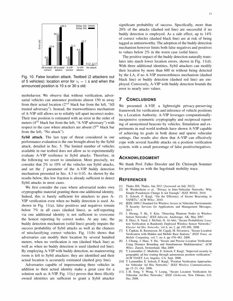
Fig. 10. False location attack. Testbed (2 attackers out
of 5 vehicles): location error for τb = 1 s and when the
announced position is 10 s or 30 s old.
misbehavior. We observe that without verification, adver-sarial vehicles can announce positions almost 150 m awayfrom their actual location (2nd black bar from the left, “Alltrusted adversary”). Instead, the trustworthiness mechanismof A-VIP still allows us to reliably tell apart incorrect nodes.Their true position is estimated with an error in the order ofmeters (4th black bar from the left, “A-VIP adversary”) withrespect to the case where attackers are absent (5th black barfrom the left, “No attack”).
Sybil attack. The last type of threat considered in ourperformance evaluation is the one brought about by the Sybilattack, detailed in Sec. 5. The limited number of vehiclesavailable in our testbed does not allow us to experimentallyevaluate A-VIP resilience to Sybil attacks. Therefore, inthe following we resort to simulation. More precisely, weconsider that 2% to 10% of the vehicles run Sybil attacks,and set the f parameter of the A-VIP buddy detectionmechanism presented in Sec. 4.3 to 0.05. As shown by theresults below, this low fraction is already sufficient to detectSybil attacks in most cases.
We first consider the case where adversarial nodes owncryptographic material granting them one additional identity.Indeed, this is barely sufficient for attackers to pass A-VIP verification even when no buddy detection is used. Asshown in Fig. 11(a), false positives and negatives remainbelow 7% in all cases (dashed lines), as self-reportingvia one additional identity is not sufficient to overcomethe honest reporting by correct nodes. At any rate, thebuddy detection mechanism (solid lines) greatly impairs thesuccess probability of Sybil attacks as well as the chancesof misclassifying correct vehicles. Fig. 11(b) shows thatadversaries can modify their location by several hundredmeters, when no verification is run (dashed black line) aswell as when no buddy detection is used (dashed red line).By employing A-VIP with buddy detection, no maneuveringroom is left to Sybil attackers: they are identified and theiractual location is accurately estimated (dashed grey line).
Adversaries capable of impersonating three vehicles inaddition to their actual identity make a great case for asolution such as A-VIP. Fig. 11(c) proves that three illicitlyowned identities are sufficient to grant a Sybil attacker
significant probability of success. Specifically, more than20% of the attacks (dashed red line) are successful if nobuddy detection is employed. As a side effect, up to 14%of correct vehicles (dashed black line) are at risk of beingtagged as untrustworthy. The adoption of the buddy detectionmechanism however limits both false negatives and positivesto values below 2% in the worst case (solid lines).
The positive impact of the buddy detection naturally trans-lates into much lower location errors, shown in Fig. 11(d).With three additional identities, Sybil attackers can modifytheir location by more than 600 m without being detectedby the LA, if no A-VIP trustworthiness mechanism (dashedblack line) or buddy detection (dashed red line) are em-ployed. Conversely, A-VIP with buddy detection bounds theerror to nearly zero values.
7 CONCLUSIONS
We presented A-VIP, a lightweight privacy-preservingframework for verification and inference of vehicle positionsby a Location Authority. A-VIP leverages computationally-inexpensive symmetric cryptography and reciprocal report-ing of anonymized beacons by vehicles. Simulation and ex-periments in real-world testbeds have shown A-VIP capableof achieving its goals in both dense and sparse vehicularsettings. Our results also show that A-VIP can effectivelycope with several feasible attacks on a position verificationsystem, with a small percentage of false positive/negatives.
ACKNOWLEDGMENT
We thank Prof. Falko Dressler and Dr. Christoph Sommerfor providing us with the Ingolstadt mobility trace.
REFERENCES
[1] Thales ISS, Thales, Jan. 2011 [Accessed on July 2012].[2] B. Wiedersheim et al., “Privacy in Inter-Vehicular Networks: Why
Simple Pseudonym Change Is not Enough,” IEEE WONS, 2010.[3] E. Schoch, F. Kargl, “On the Efficiency of Secure Beaconing in
VANETs,” ACM WiSec, 2010.[4] IEEE 1609.2 Standard for Wireless Access in Vehicular Environments
Ñ Security Services for Applications and Management Messages,2013.
[5] J. Hwang, T. He, Y. Kim, “Detecting Phantom Nodes in WirelessSensor Networks,” IEEE Infocom, Anchorage, AK, May 2007.
[6] E. Ekici, S. Vural, J. McNair, D. Al-Abri, “Secure Probabilistic Loca-tion Verification in Randomly Deployed Wireless Sensor Networks,”Elsevier Ad Hoc Networks, vol. 6, no. 2, pp. 195-209, 2008.
[7] S. Capkun, K. Rasmussen, M. Cagalj, M. Srivastava, “Secure LocationVerification with Hidden and Mobile Base Stations,” IEEE Trans. on
Mobile Computing, vol. 7, no. 4, pp. 470–483, 2008.[8] J. Chiang, J. Haas, Y. Hu, “Secure and Precise Location Verification
Using Distance Bounding and Simultaneous Multilateration,” ACM
WiSec, Zurich, Switzerland, Mar. 2009.[9] T. Leinmüller, C. Maihöfer, E. Schoch, F. Kargl, “Improved security in
geographic ad hoc routing through autonomous position verification,”ACM VANET, Los Angeles, CA, Sept. 2006.
[10] T. Leinmüller, E. Schoch, F. Kargl, “Position Verification Approachesfor Vehicular Ad Hoc Networks,” IEEE Wireless Communications,pp. 15–21, Oct. 2006.
[11] J.-H. Song, V. Wong, V. Leung, “Secure Location Verification forVehicular Ad-Hoc Networks,” IEEE Globecom, New Orleans, LO,Dec. 2008.

14
0
0.05
0.1
0.15
0.2
0.25
0.3
0.02 0.04 0.06 0.08 0.1
Rat
io
Fraction of adversaries
False positivesFalse negativesWith buddy detectionNo buddy detection
(a)
0
100
200
300
400
500
600
700
0.02 0.04 0.06 0.08 0.1
Err
or [m
]
Fraction of adversaries
All trustedA-VIP without buddy detectionA-VIP with buddy detectionCorrectAdversary
(b)
0
0.05
0.1
0.15
0.2
0.25
0.3
0.02 0.04 0.06 0.08 0.1
Rat
io
Fraction of adversaries
False positivesFalse negativesWith buddy detectionNo buddy detection
(c)
0
100
200
300
400
500
600
700
0.02 0.04 0.06 0.08 0.1
Err
or [m
]
Fraction of adversaries
All trustedA-VIP without buddy detectionA-VIP with buddy detectionCorrectAdversary
(d)
Fig. 11. Sybil attack. Simulation: adversaries own one additional identity ((a), (b)) and three additional identities((c), (d)). (a) and (c): False positives and negatives vs. fraction of attackers. (b) and (d): Location error vs. fraction
of attackers. Curves are differentiated by the combination of color and line pattern. In (a) and (c), black/red colors
indicate false positives/negatives, and solid/dashed lines the presence/absence of buddy detection. In (b) and (d),black/red/grey colors identify the cases where all nodes are trusted or A-VIP is used without/with buddy detection,
while solid/dashed curves map onto correct/adversary nodes.
[12] M. Fiore, C. Casetti, C.-F. Chiasserini, P. Papadimitratos, “Discoveryand Verification of Neighbor Positions in Mobile Ad Hoc Networks,”IEEE Transactions on Mobile Computing, vol. 12, no. 2, 2013.
[13] M. Abu-Elkheir, S.A. Hamid, H.S. Hassanein, I.M. Elhenawy, S.Elmougy, “Position verification for vehicular networks via analyzingtwo-hop neighbors information,” IEEE LCN On-Move, Bonn, Ger-many, Oct. 2011.
[14] O. Abumansoor, A. Boukerche, “A secure Cooperative Approach forNon line-of-Sight Location Verification in VANET,” IEEE Transac-
tions on Vehicular Technology, vol. 61, no. 1, pp. 275–285, 2012.[15] Z. Ren, W. Li, Q. Yang, “Location Verification for VANETs Routing,”
IEEE WiMob, Marrakech, Morocco, Oct. 2009.[16] X. Xue, N. Lin, J. Ding, Y. Ji, “A trusted neighbor table based
location verification for VANET routing,” IET ICWMMN, Beijing,China, Jan. 2010.
[17] P. Papadimitratos, L. Buttyan, T. Holczer, E. Schoch, J. Freudiger,M. Raya, Z. Ma, F. Kargl, A. Kung, and J.-P. Hubaux, “SecureVehicular Communication Systems: Design and Architecture,” IEEE
Communications Magazine, vol. 46, no. 11, pp. 100–109, Nov. 2008.[18] K. Sampigethaya, M. Li, L. Huang, R. Poovendran, “AMOEBA:
Robust Location Privacy Scheme for VANET,” IEEE JSAC, vol.25,no.8, pp.1569–1589, Oct. 2007
[19] D. Eckhoff, C. Sommer, T. Ganseny, R. German, F. Dressler, “Strongand Affordable Location Privacy in VANETs: Identity Diffusion UsingTime-Slots and Swapping,” IEEE VNC, 2010.
[20] W. Diffie, M. Hellman, “Privacy and Authentication: An Introductionto Cryptography,” Proceedings of the IEEE, vol. 67, no. 3, pp. 397–427, Mar. 1979.
[21] F. Klingler, F. Dressler, J. Cao, C. Sommer, “Use Both Lanes:Multi-channel Beaconing for Message Dissemination in VehicularNetworks,” WONS, 2013.
[22] C. Sommer, D. Eckhoff, R. German, F. Dressler, “A ComputationallyInexpensive Empirical Model of IEEE 802.11p Radio Shadowing inUrban Environments,” IEEE WONS, 2011.
[23] S.P. Boyd, L. Vandenberghe, Convex Optimization, Cambridge Uni-versity Press, 2004.
[24] S. Chang, Y. Qi, Ho. Zhu, J. Zhao, X. Shen, “Footprint: DetectingSybil Attacks in Urban Vehicular Networks,” IEEE Trans. on Paralled
and Distributed Systems, vol. 23, no. 6, pp. 1103–1114, Jun. 2012.
Francesco Malandrino (S’10, M’13) gradu-ated (summa cum laude) in Computer Engi-neering from Politecnico di Torino in 2008. Hereceived his PhD from Politecnico di Torino in2011. In 2010–2011 he has been a visitingresearcher at University of California at Irvine.His interests focus on wireless and vehicularnetworks and infrastructure management.
Carlo Borgiattino (S’12) graduated (summacum laude) in Telecommunication Engineeringfrom Politecnico di Torino in 2011. In 2012,he joined the Department of Electronics andTelecommunications of Politecnico di Torinoas a Ph.D student. His research activities arefocused on vehicular and wireless mesh net-works.
Claudio Casetti (M’05) graduated from Po-litecnico di Torino in 1992 and received hisPhD in Electronic Engineering from the sameinstitution in 1997. He is an Assistant Pro-fessor at Politecnico di Torino. He has coau-thored more than 130 papers in the fieldsof networking and holds three patents. Hisinterests focus on ad hoc wireless networksand vehicular networks.
Carla-Fabiana Chiasserini (M’98, SM’09) re-ceived her Ph.D. in 2000 from Politecnico diTorino, where she is currently an AssociateProfessor. Her research interests include pro-tocols and performance analysis of wirelessnetworks. Dr. Chiasserini has published over200 papers at major venues, and serves asAssociated Editor of several journals.
Marco Fiore (S’05, M’09) is a researcher atCNR-IEIIT, Italy, and at INRIA within the Ur-baNet team hosted by the CITI Lab of INSALyon, France. Prior to that, he was an As-sociate Professor at INSA Lyon. He receivedhis PhD degree from Politecnico di Torino, in2008. His main research interests are on mo-bile data analysis and vehicular networking.
Roberto Sadao graduated from Universidadede São Paulo (USP), Brazil, in 2009, wherehis currently a PhD student. He has been avisiting PhD student at Politecnico di Torino,Italy His research interests are in the fieldof mobile computing, context-aware systemsand IP connectivity management.