vEOS Router Configuration Guide - Arista · PDF filevEOS Router Configuration Guide Arista...
86
vEOS Router Configuration Guide Arista Networks www.arista.com 10 December, 2017
Transcript of vEOS Router Configuration Guide - Arista · PDF filevEOS Router Configuration Guide Arista...

Headquarters
5453 Great America ParkwaySanta Clara, CA 95054USA
408 547-5500
www.arista.com
Support
408 547-5502866 476-0000
Sales
408 547-5501866 497-0000
© Copyright 2017 Arista Networks, Inc. All rights reserved. The information contained herein is subject to change without notice. The trademarks, logos and service marks ("Marks") displayed in this documentation are the property of Arista Networks in the United States and other countries. Use of the Marks are subject to Arista Network’s Term of Use Policy, available at www.arista.com/en/terms-of-use. Use of marks belonging to other parties is for informational purposes only.

Contents
Chapter 1: Overview...................................................................................5
Chapter 2: vEOS Licensing........................................................................7
Chapter 3: Cloud High Availability .........................................................13Cloud HA Diagram......................................................................................................................................13Cloud HA Configuration Example...............................................................................................................14
Chapter 4: Using vEOS Router on the AWS Platform ..........................21vEOS Router Image Updates.....................................................................................................................21Amazon Machine Image (AMI) Specifications............................................................................................21Supported Instance Types..........................................................................................................................21Methods for Launching vEOS Router Instances.........................................................................................22Launching vEOS Router Instances Using AWS CloudFormation...............................................................22Launching vEOS Router Instances Using EC2 AWS Marketplace.............................................................25Network Configuration Tasks for vEOS Router Instances...........................................................................31Configuring the AWS CloudWatch Logs Agent...........................................................................................35Using User-data for Configuration of Entities and vEOS Router Instances................................................36Sample Instance User-data........................................................................................................................37
Chapter 5: Using the vEOS Router on Microsoft Azure.......................39vEOS Router Image Updates.....................................................................................................................39Supported Instance Types..........................................................................................................................39Launching vEOS Router Azure Instances..................................................................................................39Creating an Instance using the Portal Marketplace....................................................................................40Creating Instances under Azure CLI 2.0.....................................................................................................43Logging into Instance..................................................................................................................................44vEOS Router Startup-Configuration using Instance Custom-Data.............................................................45Sample Instance Custom-Data...................................................................................................................45Providing Startup-Configuration using Azure Custom-Data.......................................................................45Troubleshooting Instance............................................................................................................................46Resources...................................................................................................................................................47
Chapter 6: Hypervisors...........................................................................49VMware ESXi Hypervisor...........................................................................................................................50Launching VMware EXSi 6.0 and 6.5 ........................................................................................................50KVM............................................................................................................................................................55System Requirements................................................................................................................................55Using Libvirt to Manage vEOS VM on KVM................................................................................................56Launching vEOS in LinuxBridge Mode.......................................................................................................56Launching vEOS in SR-IOV Mode..............................................................................................................61Launching vEOS in PCI Passthrough Mode ..............................................................................................65
Chapter 7: IPsec Support.........................................................................69Supported Tunnel Types..............................................................................................................................69Requirements When Using NAT.................................................................................................................70Using IPsec on vEOS Router Instances.....................................................................................................70Topology.....................................................................................................................................................70Configuring IPsec Tunnels on vEOS Router Instances...............................................................................70Examples of Running-configs for GRE-over-IPsec Tunnels........................................................................74Examples of Running-configs for VTI IPsec Tunnels..................................................................................75Using IPsec on vEOS and Non-Arista Router Instances............................................................................76
iii

Topology.....................................................................................................................................................76Configuring GRE-over-IPsec Tunnels.........................................................................................................77Configuring VTI IPsec Tunnels....................................................................................................................79Example of Running-configs for IPsec Tunnels...........................................................................................82IPsec Show Commands..............................................................................................................................84
iv

Chapter 1Overview
vEOS Router
Arista vEOS Router is a new platform release of EOS that is supported on Amazon Web Service (AWS), MicrosoftAzure and other public clouds. It is also supported on customer equipment running Linux and VMware hypervisors.By bringing advanced network telemetry and secure IPSec VPN connectivity in a software-only package, vEOS Routerprovides a consistent, secure and universal approach to hybrid cloud networking for any virtualized cloud deployment.Use cases for vEOS Router include Secure Multi Cloud Connectivity, Interconnecting VPCs/VNets in the Public Cloud,Multi-site VPN aggregation, and Network Function Virtualization.
For additional information regarding EOS features, see the Arista EOS User Manual.
5

Chapter 2vEOS Licensing
Licensing for vEOS
The vEOS Router is available as a software subscription via the following options.
vEOS Router License types
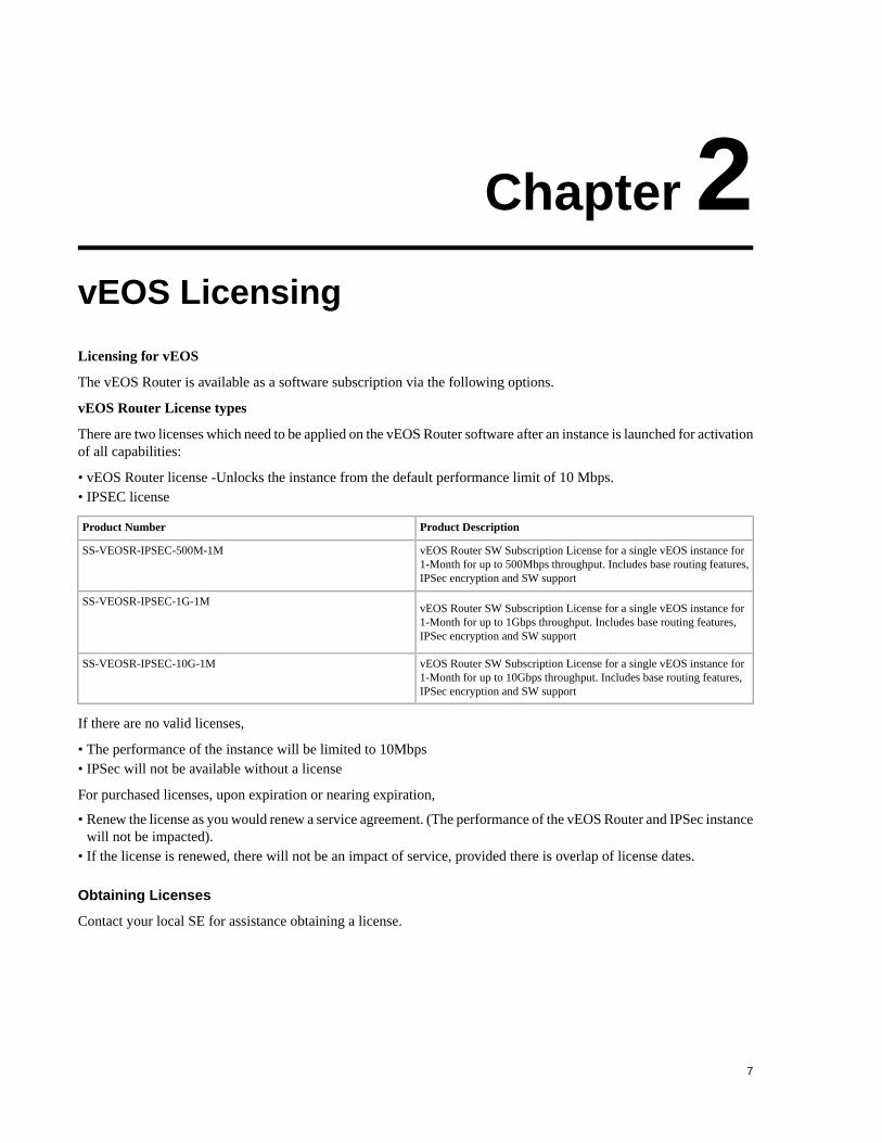
There are two licenses which need to be applied on the vEOS Router software after an instance is launched for activationof all capabilities:
• vEOS Router license -Unlocks the instance from the default performance limit of 10 Mbps.• IPSEC license
Product DescriptionProduct Number
vEOS Router SW Subscription License for a single vEOS instance for1-Month for up to 500Mbps throughput. Includes base routing features,IPSec encryption and SW support
SS-VEOSR-IPSEC-500M-1M
vEOS Router SW Subscription License for a single vEOS instance for1-Month for up to 1Gbps throughput. Includes base routing features,IPSec encryption and SW support
SS-VEOSR-IPSEC-1G-1M
vEOS Router SW Subscription License for a single vEOS instance for1-Month for up to 10Gbps throughput. Includes base routing features,IPSec encryption and SW support
SS-VEOSR-IPSEC-10G-1M
If there are no valid licenses,
• The performance of the instance will be limited to 10Mbps• IPSec will not be available without a license
For purchased licenses, upon expiration or nearing expiration,
• Renew the license as you would renew a service agreement. (The performance of the vEOS Router and IPSec instancewill not be impacted).
• If the license is renewed, there will not be an impact of service, provided there is overlap of license dates.
Obtaining Licenses
Contact your local SE for assistance obtaining a license.
7

Installing Licenses
Licenses are files that are imported via the CLI. Use the license import command to import a license file andsave it in the license store. For example purposes, the licenses below are non-functional.
vEOS11.07:22:07#license import flash:vEOSLic-1.jsonvEOS11.07:22:25#license import flash:IPSecLic-1.jsonswitch#license import http://dist/license/kvs4-v1-vEOS.json
Verifying Installed Licenses
Use the show license command to display details regarding the active licenses and device-specific informationneeded for licensing. For example purposes, the licenses below are non-functional.
vEOS11.09:58:25#show licenseSystem Serial number: 2BC6A772072B04BED43DCCF8777F036FSystem MAC address: 06:1b:8a:48:8d:0cDomain name: Unknown
License feature: IPSec License parameter: None Count: 1 Start: 2017-09-18 13:56:45 Expiration: 2017-12-30 16:00:00 Active: yes
License feature: vEOS - Virtualized EOS License parameter: None Count: 1 Start: 2017-10-08 17:00:00 Expiration: 2017-12-30 16:00:00 Active: yes
Update License (Optional)
Use the license update command to trigger an update of licenses in storage.
switch#license update
Additional Licensing Show Commands
The following CLI can be used to verify if a license is valid, when it expires, what licenses are installed and any relevantinformation regarding a license.
show license files
Use the show license files command to display all information related to the active licenses installed. Forexample purposes, the licenses below are non-functional.
vEOS12.12:28:40#show license files
License name: 2017.11.02.08.23.23.053684_IPSecLic-1yr.jsonContents:{ "BindingInfo": { "DomainAddress": "", "SerialNumber": "C3F3580316A92EE8D97DB70C967EAAA4", "SystemMAC": "02:9c:a8:a5:51:5a" }, "CustomerName": "Arista Test",
8

"Features": { "IPSec": [ { "Count": 1, "Valid": { "NotAfter": "2018-12-31T00:00:00Z", "NotBefore": "2017-11-02T15:21:22Z" }, "Value": "" } ] }, "LicenseFileVersion": "1.0", "LicenseSerialNumber": "20171102001", "Signature": { "Hash": "a202059671aa442620238df48c5b0f1e871f66945adc1f8b747ce01042b3c927", "Signature": "3046022100f5b09fabcd927d4f6986d9b2e9c2b4f75638f73bc11fb84bec5093895311c0ed022100a9316fa6aec9409f03015045a1302a33a750c5cffd45df6098d6cd600f0fa79e",
"SigningCertPEM": "-----BEGIN CERTIFICATE-----\nMIIF6TCCA9GgAwIBAgITFgAAAAN8An0siquXTAAAAAAAAzANBgkqhkiG9w0BAQsF\nADA6MTgwNgYDVQQDEy9BcmlzdGEgTmV0d29ya3MgSW50ZXJuYWwgSVQgUm9vdCBD\nZXJ0IEF1dGhvcml0eTAeFw0xNzA1MzEyMjU0MjhaFw0yNzA1MzEyMzA0MjhaMGkx\nEzARBgoJkiaJk/IsZAEZFgNjb20xHjAcBgoJkiaJk/IsZAEZFg5hcmlzdGFuZXR3\nb3JrczEyMDAGA1UEAxMpQXJpc3RhSVQtSUNBIEVDRFNBIElzc3VpbmcgQ2VydCBB\ndXRob3JpdHkwWTATBgcqhkjOPQIBBggqhkjOPQMBBwNCAARPqNqFCrbuLJ1EWkKg\n3RLdwkzx8kZxtnMmU0xTT1sLN8oNKMp4yFanvVFxwd4PydTeIlJUAZQ5a73dXqom\npHk2o4ICgjCCAn4wEAYJKwYBBAGCNxUBBAMCAQAwHQYDVR0OBBYEFHO110dbJLhN\nGJaktFHcGpdlP31KMFcGA1UdIARQME4wTAYMKwYBAgERBwEEAgEDMDwwOgYIKwYB\nBQUHAgEWLmh0dHA6Ly9pdC1wa2kuYXJpc3RhbmV0d29ya3MuY29tL3BraS9jcHMu\naHRtbAAwGQYJKwYBBAGCNxQCBAweCgBTAHUAYgBDAEEwCwYDVR0PBAQDAgGGMA8G\nA1UdEwEB/wQFMAMBAf8wHwYDVR0jBBgwFoAULe/a5u/PHHdRv1oCqSjNlACt4cow\ngYEGA1UdHwR6MHgwdqB0oHKGNmh0dHA6Ly9pdC1wa2kuYXJpc3RhbmV0d29ya3Mu\nY29tL3BraS9BcmlzdGFJVC1ST09ULmNybIY4aHR0cDovL2l0LXBraTAxLmFyaXN0\nYW5ldHdvcmtzLmNvbS9wa2kvQXJpc3RhSVQtUk9PVC5jcmwwggESBggrBgEFBQcB\nAQSCAQQwggEAMH0GCCsGAQUFBzAChnFodHRwOi8vaXQtcGtpLmFyaXN0YW5ldHdv\ncmtzLmNvbS9wa2kvQXJpc3RhSVQtUk9PVEFyaXN0YSUyME5ldHdvcmtzJTIwSW50\nZXJuYWwlMjBJVCUyMFJvb3QlMjBDZXJ0JTIwQXV0aG9yaXR5LmNydDB/BggrBgEF\nBQcwAoZzaHR0cDovL2l0LXBraTAxLmFyaXN0YW5ldHdvcmtzLmNvbS9wa2kvQXJp\nc3RhSVQtUk9PVEFyaXN0YSUyME5ldHdvcmtzJTIwSW50ZXJuYWwlMjBJVCUyMFJv\nb3QlMjBDZXJ0JTIwQXV0aG9yaXR5LmNydDANBgkqhkiG9w0BAQsFAAOCAgEAotuJ\n/hLxKlJOs85pYfbDR8bg5HzsEVHOrc/fjUf85e3riGMh+PaQHj5L++Ah9cMmUujh\n+bPq8ycrjhyYwi0IZGLjwJuGWHQ2TMXqB4o+lmKGchpR0gA31pcZCANt5atRghrQ\nhTMHN3L5CZRDn3JSCD1xQbW/WVDYlHv6IpWkd2orem/lgQfKVwVlkeB3YPJn5Hka\nHlx37mksQ9KEh7v52Tira5JnP67mUdT1C+gvdGF3DJk3Lg7GWX9Uxo1vG28AmJOU\n0n28ek5Ynh0T3uQ+jkMoJEIlyH1fKZ6zyK0sf+yLRb7brkfssZDrRIatxKEkv6Oc\nh4kXO2mvvMJxQDf7VvGXEC3fSRURLwPz//6JMx942iOKsES8ZT9nT2q9MxJXfInn\n3EcKGmPWKQR4n2qHfmq6sfk2eFBUYIrZBm9RUbVbyLZLCOv2KxJ7FFZ9LV1jp5An\nAyHLJUMQqqw/kvUUvUq1bI/PtEOlNc9Ndt/3yeh+HByzIw8/f+gjKkUjQpVncuqS\nkFotBPNNj/LjbQD40R/tJ0z/8sPXCGJuo4mE9s/MwnWmkAHxpZyCccMBlNp3LkJk\nFHcsVb36Vclv5XWDe5AxU+0sQjEB4LGP7nYo8wjjvSZIpYXRiAmDRGuAGi/W/W3F\n6hEQ661JK4KPJvoQsMqYaO/TkZPIXEAdgEDkmj0=\n-----END CERTIFICATE-----\n" }}
License name: 2017.11.03.12.27.24.016515_vEOSLic-1234.jsonContents:{ "BindingInfo": { "DomainAddress": "", "SerialNumber": "C3F3580316A92EE8D97DB70C967EAAA4", "SystemMAC": "" }, "CustomerName": "Arista Test", "Features": { "vEOS": [ {
9
vEOS Licensing

"Count": 1, "Valid": { "NotAfter": "2018-12-31T00:00:00Z", "NotBefore": "2017-11-02T00:00:00Z" }, "Value": "" } ] }, "LicenseFileVersion": "1.0", "LicenseSerialNumber": "20171103102", "Signature": { "Hash": "c488b6385257d1f8653204d1336226b2c444eb425b0ed2f72c992fb2024a40f7", "Signature": "304602210090f4c2fd60d3b46aa16a04a667aaa38783f6c37ebc0307e09e4045a2414bc9d7022100e6dd82bba3580081137726a43bbd33c557168ef5f6d1d529005f2f48569f8946", "SigningCertPEM": "-----BEGIN CERTIFICATE-----\nMIIF6TCCA9GgAwIBAgITFgAAAAN8An0siquXTAAAAAAAAzANBgkqhkiG9w0BAQsF\nADA6MTgwNgYDVQQDEy9BcmlzdGEgTmV0d29ya3MgSW50ZXJuYWwgSVQgUm9vdCBD\nZXJ0IEF1dGhvcml0eTAeFw0xNzA1MzEyMjU0MjhaFw0yNzA1MzEyMzA0MjhaMGkx\nEzARBgoJkiaJk/IsZAEZFgNjb20xHjAcBgoJkiaJk/IsZAEZFg5hcmlzdGFuZXR3\nb3JrczEyMDAGA1UEAxMpQXJpc3RhSVQtSUNBIEVDRFNBIElzc3VpbmcgQ2VydCBB\ndXRob3JpdHkwWTATBgcqhkjOPQIBBggqhkjOPQMBBwNCAARPqNqFCrbuLJ1EWkKg\n3RLdwkzx8kZxtnMmU0xTT1sLN8oNKMp4yFanvVFxwd4PydTeIlJUAZQ5a73dXqom\npHk2o4ICgjCCAn4wEAYJKwYBBAGCNxUBBAMCAQAwHQYDVR0OBBYEFHO110dbJLhN\nGJaktFHcGpdlP31KMFcGA1UdIARQME4wTAYMKwYBAgERBwEEAgEDMDwwOgYIKwYB\nBQUHAgEWLmh0dHA6Ly9pdC1wa2kuYXJpc3RhbmV0d29ya3MuY29tL3BraS9jcHMu\naHRtbAAwGQYJKwYBBAGCNxQCBAweCgBTAHUAYgBDAEEwCwYDVR0PBAQDAgGGMA8G\nA1UdEwEB/wQFMAMBAf8wHwYDVR0jBBgwFoAULe/a5u/PHHdRv1oCqSjNlACt4cow\ngYEGA1UdHwR6MHgwdqB0oHKGNmh0dHA6Ly9pdC1wa2kuYXJpc3RhbmV0d29ya3Mu\nY29tL3BraS9BcmlzdGFJVC1ST09ULmNybIY4aHR0cDovL2l0LXBraTAxLmFyaXN0\nYW5ldHdvcmtzLmNvbS9wa2kvQXJpc3RhSVQtUk9PVC5jcmwwggESBggrBgEFBQcB\nAQSCAQQwggEAMH0GCCsGAQUFBzAChnFodHRwOi8vaXQtcGtpLmFyaXN0YW5ldHdv\ncmtzLmNvbS9wa2kvQXJpc3RhSVQtUk9PVEFyaXN0YSUyME5ldHdvcmtzJTIwSW50\nZXJuYWwlMjBJVCUyMFJvb3QlMjBDZXJ0JTIwQXV0aG9yaXR5LmNydDB/BggrBgEF\nBQcwAoZzaHR0cDovL2l0LXBraTAxLmFyaXN0YW5ldHdvcmtzLmNvbS9wa2kvQXJp\nc3RhSVQtUk9PVEFyaXN0YSUyME5ldHdvcmtzJTIwSW50ZXJuYWwlMjBJVCUyMFJv\nb3QlMjBDZXJ0JTIwQXV0aG9yaXR5LmNydDANBgkqhkiG9w0BAQsFAAOCAgEAotuJ\n/hLxKlJOs85pYfbDR8bg5HzsEVHOrc/fjUf85e3riGMh+PaQHj5L++Ah9cMmUujh\n+bPq8ycrjhyYwi0IZGLjwJuGWHQ2TMXqB4o+lmKGchpR0gA31pcZCANt5atRghrQ\nhTMHN3L5CZRDn3JSCD1xQbW/WVDYlHv6IpWkd2orem/lgQfKVwVlkeB3YPJn5Hka\nHlx37mksQ9KEh7v52Tira5JnP67mUdT1C+gvdGF3DJk3Lg7GWX9Uxo1vG28AmJOU\n0n28ek5Ynh0T3uQ+jkMoJEIlyH1fKZ6zyK0sf+yLRb7brkfssZDrRIatxKEkv6Oc\nh4kXO2mvvMJxQDf7VvGXEC3fSRURLwPz//6JMx942iOKsES8ZT9nT2q9MxJXfInn\n3EcKGmPWKQR4n2qHfmq6sfk2eFBUYIrZBm9RUbVbyLZLCOv2KxJ7FFZ9LV1jp5An\nAyHLJUMQqqw/kvUUvUq1bI/PtEOlNc9Ndt/3yeh+HByzIw8/f+gjKkUjQpVncuqS\nkFotBPNNj/LjbQD40R/tJ0z/8sPXCGJuo4mE9s/MwnWmkAHxpZyCccMBlNp3LkJk\nFHcsVb36Vclv5XWDe5AxU+0sQjEB4LGP7nYo8wjjvSZIpYXRiAmDRGuAGi/W/W3F\n6hEQ661JK4KPJvoQsMqYaO/TkZPIXEAdgEDkmj0=\n-----END CERTIFICATE-----\n"
show license files compressed
Use the show license files compressed command to display license information. In this example, thefiles are zipped then base64 encoded. For example purposes, the licenses below are non-functional.
vEOS12.12:35:36#show license files compressed
License name: 2017.11.02.08.23.23.053684_IPSecLic-1yr.jsonContents:eJyVVlmzokga/SsVvt65Y7IKN2Iekh0EFARchnlgV5BEBUGsqP/eiXVrqqK7o3uGMCLJL0+ePN+W8nUmnFB6QoWO8mb28eXrTGrq6IRgmt6ytsWW2ewfX2ab7HaKzva9jrPbZBMphWI4QBEs5ElZ5iR+IQkLIPLsQoYQ0q89Y9tltQXFaQMgP/jkI+I+IuaDIT6YaPYNQ8R72zV1drOjOptQ8HZqu+iLl7XdxKBkUXfHMl669PUmS/Dbv7/OxOaOOvxKYEwQnU/pC2A3Hcy77/pIQHDvBPlOER4AH6/fYWLEGCHLm1v2CVq8E8Q7ID2C+SCJD5I8vGRhzvsLMfv2n2lunpIMtZlyOmdBdmtPDZoWiX+C2c/F30doIicIQAJAvIJxKtDLmZdULWqPEygiMYDBQSOiiKZJFk8pLs1pLmFikBMZtyByluVpJkoTIufiBb1IMkAAmoyphCcXv2eeUYBmAUkSAOSYgc+jOEkxLqVzlufYlI/JjE/ImM4XDEtx+YKKE4LIY46Os4QBPMXxDEUQCcjS7ywRj1OcR2yUJTyN+QAFCAZgPQQFyIiiogUDEibJ85Rm0pwFPJeyScri40EeLfjsh0BcYGJ269ayNal8nx5BVnX7iyi7nq7oIvTklzVElq4rrCeKkFcLOOgCLHRPKXBRQZuDCLSn633nwc/nCW2hqK7H6qTyAxCg0yohghJkLa8Y7GIvBY4jySMvJPX5mapy4dUBSEl+jCir2GwZcNgZ9/12KDaBU/g136eiIIUIW4EuK0SqHnu8E2QezJQBPOwnJKynPFqlD6zyGGHb+F/bE75sllo9QiQ/oSsUjVGdIqOa6+0BygelsMuYBA+thMkf15jjd43K/bBzqRDFlHFLJl4JqpDwZfiwLs7OuCSUe8Rqu41vC7ocSK4yjednQgWXuE4KhwxG7IUQonTnNpjlkmrVsPWgJxQJjlS5Wju6IBTF57slCIMtQuiur/ZVEW/x3TQIeVstixBRrpkO1fPBVYdHh6zaBw/PI1rT5hp
10

7aV3oUYlQHyiPIaXXY+pl+tnw4cFhogWV7q5NHaKLVpENrYtFiTOK6EGGe2M57AUBqqL98PFoidCBg+bgXLlgJQh7WdFWuHPS2DCPdohUI6o6RUvUS3peU8TSUpIpHqkOXceS6cGDe2tihIXsCoMs41GypGFYFXt9sodIcHwNW7dmfQSpBllz5C+pSAwRWd33nxGNf9bFfU/ynUkJt2jDl4lm3UMUaW4XQziozq/qHVGAQyYWggc1H+4LQYKyPIjDy5M1LkYJFqpqQU7FNYkVy4MszAdHsaAlwJwbtO/IEidjUBrom9k8Yu7ztaalbk804nVT2mcodnTSDCEq9vLLb21wWUsrhvQqgEZbqvb/6FWIfvHrsx8UIxCJjQd436ztMdb3NPYUJFLTm+QZmDuM9eDDrJUx2tkAM2yZc6qluCe6J97Rxxt+Oq//tS79il8HIlMm9TAUhbzBlXYTClkRnATnAjobnG9nWoGWBlRRbFXo+IrwhOIRKU2qucPqxPXRzukStbv8OPvHySH627Plzx0bf7Tkn3oNTx+mjn9199TzZ6sUsP8YpRh9TDnTXJo6f0I6uwBEKo7czmWm2KSSMP/hyVRRyQCbw/OvovVXscJe/B+K/0zvdD/8neI/3o0QrkTcCbDp7kaI5kfzsTwbq5ZjLvs8llwuLhjt2cqBtrol87z0c47JqNtJtY5v68jRSsZ8e4NHPsE3wb08hugtXl+5MbmVx3E/nIB+UM1yMO7qVnNIz9pdBbp5O9dLNTleXFBAirgkBxHaHRN1bnG8OSE6epZmUyYjHlwJUcZGlIiHE2/n20Dan7We1S/bKiXxH3Y9PxdOvgyG4FxlArVfG4jRqihE2vlBLeqqdfilfFz0DOmdbhFjoDW7qP3UI8S3oseVTklGRZnFQt3ueP/REL1KcrA2Vn6IACK5rGL26Ag86u68lZXVGLJ+HjUiXx7Y57gEbf42mm68iG9V3rYH6ebqUfdYylXPrhLsBV3tVmTd95bxcKR8EfTqThapfOP6rjmsn/M5a1gPniZPq2Urb7iDxyOPvPLWw9jlOkL4ppWTpVqvt0vHpRF51fL6yrZ5RWaK4O/120GoedePg3g0D6a46snlw1goyoE3A6K8MBAzwFEzDd9yrtdhXvW+3/tXItbn605ene2Et9NuTo3Z8U0Txqc+cPP8rSiXlV86lwAl9+smRJWCv47Wtl3OzTJ2JBq4884AzznXrneiatwbupb5dm4NaFtXUHtcDqOYJJZwti+UWRlViPA13QYxxQbJuWd2Wylj4MN/A61TygJtqusF2jfcUJb95qBf9jv3BGvJVe9QPc1xyincWexRdliWMJb0cm30jdNa1320mnvVYa3vZJjiy72qS/CvEL0+F2Rb+pNPiNm3b78BeoV2YA==
License name: 2017.11.03.12.27.24.016515_vEOSLic-1234.jsonContents:eJyVVlmvozgW/iul+3qnJmaHlubBgNkCJBAgy2Qe2BMIJgkEkpTqv7fJvTVd6m51zyAkm+Pj4+87G/72Jh9xdsSliYv27Zcv397UtomPGGbZNe86Inl7+8eXt1V+PcYn99Yk+XWSKYzGcCJgKB5KNEKiKgmqLABF4gUEIWRfex5dnzcOVF5GvhOJcuv6tsmvbtzkkxBej10ffwnyrp82aHnc38ipLxgDWqzI5N/f3pT2hnsypYhKFJ+O2WvdbXtY9B9oaECJXyn6K0MFAPzyeneTQaIj50V7zT+VhK8U9RXQPyl9/7B5yz8w/mf6to9pjrtcO57yKL92xxZPi9Q/wdtvi7/3x2Scoog/AP2ifizxi8sLqhF3h0kpZUUx4RmRozkhowqR5xgasBnFMDxN8wmdsiybJyzNJSDP6EKgU0mii4QGNBuzoBB+b/mNASwPaJoCQAIFm9JFxoOMSVg+jik+BmzM80Icx4woiEzBp4yQJylggJADKWcBy8U0S7FJKmXCh5WczzKRTpJ4ii0QKYoRBJqPWSZJMoZJOU6geDEvuILPqIyjJQC4gi5YkeOlQpRY/dAkk5Kfu2XyJlQfp0eGemm0VBfmBqpgID9JLusWOaGh8oCpT0Eo6mDEsz0EqSQtAVIQbd8XLbBPDzeUJXLuvLoT7q0ghk6HXaHkMV8k5Qjm65VSPPU9FDktPm9Mx0VAZNBDJaesSMU67WHNhtrNt2PZaryCvDRhoyRVb3mEiBiTQq0w8D2QnyAObaCO7uE1LOEz2cKgROdYiJ7PFf2RO+ZI5e3/cYPaEvl61VH2OrnpndDqKdVroVid3dqGD6xzXu8IFRu+02PrPHCWNd08muCnVIhQjenbO3sc4p4x8I2n4VurKJItXXpvH0TJnonDRp6dHRg7CQ9zjb+C2xcs6MelwHMJDLlHiqWiw9U5bL8nPuyPLoKhD6y4t70ZRrcrMtCq3rebnHjG9nY/28i/Xu3mOnCcE9CKjOdsXWnTtn9qHFeIi0+5ixy0cW5ObJCuHO42KByTaXttnjs1HTLWsqZUUiitkRwa01H7eyDHXFvYdkdBTowdHwSKx8sJDlLdKMBamcLLHsg7vHuhXXvWak+jk7LRlq7mjp5I/MhL7nIHYM4NaZLMIS+fKIEBlVRx3HRbk1J/key15oEOnabg4gMyBvP6RzplBjTNe37adHk9/y4ralpd5m5Gu8kqrUcG57HBt+n0A46t7P6D1FhmOulHIAjRBuS1mFCI3K+GKyJMmowlLXHSjqJCcJYjQieTZ6mgMdGRbiaHxoViQYo9bC0M5nMXebLQ0j8weqVS6ryj1BpWfTdtzjcotevI3R5x2jHLOLDFpjrrv/I6s9/onXZz1oVqRQqwBIod24j8TcsoQpSNV2sOkTsDdEN4B3u9Ee8cYFxMKaO2VGRmqif5IdQ7KSpvOGn/MyrKVlpHBV2oxjWaIVybSrXCJN9lISC+itSLy9aQU6BtAVpdOhF2ryEyoHrLWZ4Y+LozjEG69P9f784+wfJ+/x356NPneswoeDfsNrBeY4VfyruqeaPzmVTPgTLc0aEsabvtWp8idNbxOBWCee2/jc5JtMlWc/mEwZlY6w3T3/ylt/5SvC4v9A/Gd4p/7wd4j/2BshXCikEmDb36w9nh3s+/xkLTqRO2+LRPXFpOSMZ4ciY3FNZ0UVFiKXM9ej7hzel7FnVJz9/g4PUko6wa067PF7sryIj/RaHR7b8QjMnW5Xo3XT14ZHB87mIrPt+6mZ6+nh7IMSMtQ53SnQ7bm498vD1dvjQ+AYLmNzys5XMWOtFJW6e8l6to7U7ckYePO8rjOa/LCb2an0ink0Rqc6l5nt0sKcUcd7bJzujNDUnSfN0UEYODo4XmPOwkteaMIsoJT3ciCZzqhWzdiloK83UnhvqUGnRdhYi3CPAabFvOa2+AAC5ua9V7XTWsg8PQyqmO/452MOuuL9YfuJkFzrout26tU34/4+R/XAL1LCgq03C7oZBse6e2ohRIO+QQpTrPzQt8flczbjLecusfRxMe/QStwFEg7oi+TcrU1hYkw6LUrnerNczz2fxfTFKJoL3xU1nWtyuDWvO7mR/CJkoe9s5XFQM/lqBpO8mOqOrMQWIBPgzbCh3vchln9RCGQ3ihEnO27NHi5KaSm/z5pEf3g358TRHcVa8l9W8DivvHOH0dlntca2R29HSdauZXSWeygJ/1lvgORO75UbRrVvLNkjqZs6I100Njft591DS1JFP7pmxa6veY9Kmuyhh+Cg9DdxmreYcvIfvoPMqJLO2vhTwthXHqhpWO/O83fhH2Ki+foP6cUZCzpDK4g/I43nKmrPzpTW0XudctvFiFtS7pblBMCPNvW4q8K89fl0XkKv+yRXi7fv3XwGKSHAv
show license expired
The show license expired command will display the same as the show license command, but with expiredlicenses only displayed.
vEOS11.09:58:31#show license expiredSystem Serial number: 2BC6A772072B04BED43DCCF8777F036FSystem MAC address: 06:1b:8a:48:8d:0cDomain name: Unknown
License feature: IPSec License parameter: None Count: 1 Start: 2017-10-05 21:49:13 Expiration: 2017-10-09 17:00:00 Active: expired
11
vEOS Licensing

License feature: vEOS - Virtualized EOS License parameter: None Count: 1 Start: 2017-10-05 21:47:34 Expiration: 2017-10-09 17:00:00 Active: expired
show license all
The show license all command will display all licenses that are active, expired or licenses that have not beenactivated yet.
vEOS11.09:58:38#show license allSystem Serial number: 2BC6A772072B04BED43DCCF8777F036FSystem MAC address: 06:1b:8a:48:8d:0cDomain name: Unknown
License feature: IPSec License parameter: None Count: 1 Start: 2017-12-30 16:00:00 Expiration: 2018-12-30 16:00:00 Active: in future
License parameter: None Count: 1 Start: 2017-09-18 13:56:45 Expiration: 2017-12-30 16:00:00 Active: yes
License parameter: None Count: 1 Start: 2017-10-05 21:49:13 Expiration: 2017-10-09 17:00:00 Active: expired
License feature: vEOS - Virtualized EOS License parameter: None Count: 1 Start: 2017-10-08 17:00:00 Expiration: 2017-12-30 16:00:00 Active: yes
License parameter: None Count: 1 Start: 2017-12-30 16:00:00 Expiration: 2018-12-30 16:00:00 Active: in future
License parameter: None Count: 1 Start: 2017-10-05 21:47:34 Expiration: 2017-10-09 17:00:00 Active: expired
12

Chapter 3Cloud High Availability
The cloud providers also have the concept of a network called VPC in AWS or VNet in Azure, which is a logicalrepresentation of a single network that is visible to customers. VPCs or VNets cannot span across regions. The logicalnetworks can be partitioned into subnets, which can each be assigned separate routing tables to control egress trafficfrom hosts in the subnets.
In the cloud, failures can occur that affect the availability of virtual router instances in the same Fault Domain/AvailabilityZone. If all instances affected by such a failure are hosted in a single location, all resources become unavailable. It isrecommended that resources are partitioned into availability zones to provide minimal downtime for applications.
A vEOS Router instance, deployed as an edge router or as a transit router, can carry traffic between the cloud networksor between the cloud and the on-premise data center. The vEOS Router instance uses IPsec or GRE tunnels to carrydata traffic, and are in the critical network path for cloud applications.
The Cloud HA feature adds support to make the vEOS Router deployment more resilient to various failure scenariosin the cloud, such as:
• vEOS Router instance goes down due to underlying cloud infrastructure issues.• vEOS Router instance is unable to forward traffic due to connectivity issues in the cloud infrastructure.• vEOS Router experiences an internal issue leading to unavailability.
The Cloud High Availability (Cloud HA) feature adds support for an active-active deployment model in different FaultDomains/Availability Zones. The cloud “subnets” within the same logical network (VPC/VNET) are partitioned andassigned to one of the vEOS Router HA instances. The two vEOS Router instances will continuously monitor eachother for aliveness using Bidirectional Forwarding Detection (BFD) running on either a native interface or via a tunnelinterface between the two instances. In case of network connectivity issues or failure in a vEOS Router instance and/orthe cloud infrastructure, the peer vEOS Router instance will take over the traffic in subnets from the down instance,providing fault resilience.
Cloud HA DiagramThis diagram shows an example of a vEOS Router Cloud HA implementation.
13

Note: For a configuration example based on this diagram, see Cloud HA Configuration Example on page14.
Cloud HA Configuration ExampleThis example configuration is based on the Cloud HA implementation diagram. The point of reference of theconfiguration is the vEOS Router instance "vEOS 1" in the Edge Virtual Network.
14

Cloud HA configurations are applied using the JSON Cloud HA configuration file (cloud_ha_config.json). Thefile path for the configuration file is /mnt/flash/cloud_ha_config.json. The configuration takeseffect as soon as the configuration file is created or whenever the file is updated. In the case of updates, theconfiguration is re-applied.
The example includes specific configurations for various aspects of the Cloud HA implementation. The specificconfigurations are:
• General Configuration on page 15• BFD Configuration on page 15• Cloud Configuration on page 15• Routing Configuration on page 17• Peer Routing Configuration on page 17
Note: The last two configurations represent full Cloud HA implementation configurations, including onefull configuration for Cloud HA on AWS, and one for Cloud HA on Azure.
• AWS Full Configuration on page 18• Azure Full Configuration on page 19
General Configuration
To enable the Cloud HA feature and set the hysteresis timer (the wait time to recover local subnets traffic afterfailure recovery), use the following general configuration.
Note: Hysteresis time should not be set to less than 20 seconds.
"generalConfig" : { "enable_optional" : "true", "hysteresis_time_optional" : "20" }
BFD Configuration
To configure the BFD link between the HA pair of vEOS Routers that is used to detect peer failure, the peer IPaddress and local BFD source interface must be provided. The peerVeosIp address can be any reachable addressof the peer vEOS router (direct or tunnel). The bfdSourceInterface corresponds to local vEOS router interfaceto be used for reaching peerVeosIp address.
"bfdConfig" : { "peerVeosIp" : "10.1.0.5", "bfdSourceInterface" : "Ethernet1" }
Cloud Configuration
In order to have access to the cloud services, the vEOS Router must be provided with credentials. Additionally,a proxy may be configured for the connection to the cloud services to go through.
AWS
In AWS, a region must be specified. It is recommended to authorize the vEOS Router by assigning it an IAMrole, but optionally an explicit credential can be specified.
"awsConfig" : { "region" : "us-west-1", "aws_credentials_optional": { "aws_access_key_id" : "AKIAIOSFODNN7EXAMPLE",
15
Cloud High Availability

"aws_secret_access_key" : "wJalrXUtnFEMI/K7MDENG/bPxRfiCYEXAMPLEKEY" }, "http_proxy_optional": { "http_port_optional" : "3128", "http_proxy_port_optional" : "3128" , "http_proxy_optional" : "10.1.0.10", "http_proxy_user_optional" : "JohnDoe", "http_proxy_password_optional" : "MyPassword" } }
Azure
There are two authorization models that can be used in Azure: SDK Auth Credentials and Active DirectoryCredentials. SDK Auth Credentials are the recommended authorization model.
• SDK Auth Credentials
To generate SDK Auth Credentials please follow the instructions on this page:https://docs.microsoft.com/en-us/cli/azure/ad/sp?view=azure-cli-latest#az_ad_sp_create_for_rbac.
"azureSdkAuthCredentials" : { "clientId": "e817439781-b494-474c-a138-7d1dawefj3902", "clientSecret": "f5e873436-a1a5-4a1d-b5d8-203fdasdfb5bc3", "subscriptionId": "ef16892c-aa46-4aba-ae9a-d4fhsb1c612c", "tenantId": "5haf781ec-cb78-48ea-a1df-1a95dfjd809946e", "activeDirectoryEndpointUrl": "https://login.microsoftonline.com", "resourceManagerEndpointUrl": "https://management.azure.com/", "activeDirectoryGraphResourceId": "https://graph.windows.net/", "sqlManagementEndpointUrl": "https://management.core.windows.net:8443/",
"galleryEndpointUrl": "https://gallery.azure.com/", "managementEndpointUrl": "https://management.core.windows.net/" }
• Active Directory Credentials
To authorize using Active Directory credentials, a username and password are required.
"azureActiveDirectoryCredentials" : { "email" : "[email protected]", "password" : "MyPassword", "subscriptionId" : "ef16892c-aa46-4aba-ae9a-d4fhsb1c612c" }
A full example of the Azure Configuration section is given below, using the SDK Auth credential model.
"azureConfig" : { "azureSdkAuthCredentials" : { "clientId": "e817439781-b494-474c-a138-7d1dawefj3902", "clientSecret": "f5e873436-a1a5-4a1d-b5d8-203fdasdfb5bc3", "subscriptionId": "ef16892c-aa46-4aba-ae9a-d4fhsb1c612c", "tenantId": "5haf781ec-cb78-48ea-a1df-1a95dfjd809946e", "activeDirectoryEndpointUrl": "https://login.microsoftonline.com", "resourceManagerEndpointUrl": "https://management.azure.com/", "activeDirectoryGraphResourceId": "https://graph.windows.net/", "sqlManagementEndpointUrl": "https://management.core.windows.net:8443/",
"galleryEndpointUrl": "https://gallery.azure.com/", "managementEndpointUrl": "https://management.core.windows.net/" }, "http_proxy_optional": "http://10.1.0.10:3128",
16

"https_proxy_optional": "http://johndoe:[email protected]:3120/" }
Routing Configuration
In order to program the route tables with the proper local routes during steady state, and the peer routes duringfailover, the individual routes must be specified in the Cloud HA config.
As per the example above, we must configure the necessary route in Route Table 1 in the local routingconfiguration, and the necessary routes in both Route Table 2 and Route Table 3 in the peer routing configuration.
For vEOS 2, we would configure Route Table 2 and Route Table 3 in the local routing configuration, and RouteTable 1 in the peer routing configuration. The configuration for vEOS 2 is not shown in this document.
Local Routing Configuration
AWS
In this section the routeTableId specified is for AWS route table ID rtb-17135a73 (shown as Route Table 1 inabove diagram), the destination selects the individual route within the route table we wish to control, and therouteTarget points to the interface id eni-867caa86 (from AWS perspective) of the vEOS Router that trafficshould be directed to. Please note that this interface ID belongs to this vEOS instance and represented as"Ethernet-<n>" in EOS configs.
"awsLocalRoutingConfig" : { "routeTableIdAndRouteNetworkInterface" : [ { "routeTableId" : "rtb-17135a73", "destination": "0.0.0.0/0", "routeTarget" : "eni-867caa86" } , ] }
Azure
In this section the resource group specified is the one which contains the route table referenced beneath it. TherouteTableName identifies Route Table 1, and the prefix selects the individual route within Route Table 1 wewish to control. The nextHopIp field uses the IP of the vEOS Router interface that traffic should be directed to.
"azureLocalRoutingConfig" : { "resourceGroupName" : "MyResourceGroup", "routeTables" : [ { "routeTableName" : "RouteTable1", "routes" : [ { "prefix" : "0.0.0.0/0", "nextHopIp" : "10.1.0.4" } ] } ] }
Peer Routing Configuration
As was done for the local configuration with Route Table 1, we must also configure Route Table 2 and RouteTable 3 to point to vEOS 1 during failover. Please note that the routeTarget refers to this vEOS router's localinterface.
AWS
"awsPeerRoutingConfig" : { "routeTableIdAndRouteNetworkInterface" : [
17
Cloud High Availability

{ "routeTableId" : "rtb-33585b73", "destination": "0.0.0.0/0", "routeTarget" : "eni-867caa86" } , { "routeTableId" : "rtb-2843124c", "destination": "0.0.0.0/0", "routeTarget" : "eni-867caa86" } ] }
Azure
"azurePeerRoutingConfig" : { "resourceGroupName" : "MyResourceGroup", "routeTables" : [ { "routeTableName" : "RouteTable2", "routes" : [ { "prefix" : "0.0.0.0/0", "nextHopIp" : "10.1.0.4" } ] }, { "routeTableName" : "RouteTable3", "routes" : [ { "prefix" : "0.0.0.0/0", "nextHopIp" : "10.1.0.4" } ] } ] }
AWS Full Configuration
{ "generalConfig" : { "enable_optional" : "true", "hysteresis_time_optional" : "20" }, "bfdConfig" : { "peerVeosIp" : "10.1.0.5", "bfdSourceInterface" : "Ethernet1" }, "awsConfig" : { "region" : "us-west-1", "aws_credentials_optional": { "aws_access_key_id" : "AKIAIOSFODNN7EXAMPLE", "aws_secret_access_key" : "wJalrXUtnFEMI/K7MDENG/bPxRfiCYEXAMPLEKEY" }, "http_proxy_optional": { "http_port_optional" : "3128", "http_proxy_port_optional" : "3128" , "http_proxy_optional" : "10.1.0.10", "http_proxy_user_optional" : "JohnDoe", "http_proxy_password_optional" : "MyPassword" } }, "awsLocalRoutingConfig" : { "routeTableIdAndRouteNetworkInterface" : [
18

{ "routeTableId" : "rtb-17135a73", "destination": "0.0.0.0/0", "routeTarget" : "eni-867caa86" } , ] }, "awsPeerRoutingConfig" : { "routeTableIdAndRouteNetworkInterface" : [ { "routeTableId" : "rtb-33585b73", "destination": "0.0.0.0/0", "routeTarget" : "eni-867caa86" } , { "routeTableId" : "rtb-2843124c", "destination": "0.0.0.0/0", "routeTarget" : "eni-867caa86" } ] }}
Azure Full Configuration
{ "generalConfig" : { "enable_optional" : "true", "hysteresis_time_optional" : "20" }, "bfdConfig" : { "peerVeosIp" : "10.1.0.5", "bfdSourceInterface" : "Ethernet1" }, "azureConfig" : { "azureSdkAuthCredentials" : { "clientId": "e817439781-b494-474c-a138-7d1dawefj3902", "clientSecret": "f5e873436-a1a5-4a1d-b5d8-203fdasdfb5bc3", "subscriptionId": "ef16892c-aa46-4aba-ae9a-d4fhsb1c612c", "tenantId": "5haf781ec-cb78-48ea-a1df-1a95dfjd809946e", "activeDirectoryEndpointUrl": "https://login.microsoftonline.com", "resourceManagerEndpointUrl": "https://management.azure.com/",
"activeDirectoryGraphResourceId": "https://graph.windows.net/",
"sqlManagementEndpointUrl": "https://management.core.windows.net:8443/", "galleryEndpointUrl": "https://gallery.azure.com/", "managementEndpointUrl": "https://management.core.windows.net/"
}, "http_proxy_optional": "http://10.1.0.10:3128", "https_proxy_optional": "http://johndoe:[email protected]:3120/"
}, "azureLocalRoutingConfig" : { "resourceGroupName" : "MyResourceGroup", "routeTables" : [ { "routeTableName" : "RouteTable1", "routes" : [ { "prefix" : "0.0.0.0/0", "nextHopIp" : "10.1.0.4" } ] } ] },
19
Cloud High Availability

"azurePeerRoutingConfig" : { "resourceGroupName" : "MyResourceGroup", "routeTables" : [ { "routeTableName" : "RouteTable2", "routes" : [ { "prefix" : "0.0.0.0/0", "nextHopIp" : "10.1.0.4" } ] }, { "routeTableName" : "RouteTable3", "routes" : [ { "prefix" : "0.0.0.0/0", "nextHopIp" : "10.1.0.4" } ] } ] }}
20
Chapter 4Using vEOS Router on the AWS Platform
vEOS Router, which is based on the Arista EOS, runs as a virtual machine instance on AWS EC2. You use vEOSRouter to create the various types of virtual machine router instances you need for your AWS deployment (for example,edge routers and transit routers).
vEOS Router Image UpdatesThe process you use to update vEOS Router images is the standard update process used for EOS images.
For details on the steps to use, refer to the Arista EOS User Manual (seehttps://www.arista.com/en/support/product-documentation).
Amazon Machine Image (AMI) SpecificationsThe AMI provided by Arista utilizes the architecture, type of root device, virtualization type, and interface typerequired to configure the vEOS Router for a robust AWS deployment.
The specifications of the Arista AMI are:
• Architecture: x86_64• Virtualization type: HVM• Root Device Type: EBS• Network Interface type: SR-IOV, ENA (Elastic Network Adapter)
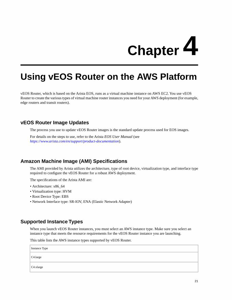
Supported Instance TypesWhen you launch vEOS Router instances, you must select an AWS instance type. Make sure you select aninstance type that meets the resource requirements for the vEOS Router instance you are launching.
This table lists the AWS instance types supported by vEOS Router.
Instance Type
C4.large
C4.xlarge
21

C4.2xlarge
R4.large
R4.xlarge
R4.2xlarge
R4.4xlarge
T2 small
T2 medium
For details on these AWS instance types, see Amazon's documentation(https://aws.amazon.com/ec2/instance-types/).
Methods for Launching vEOS Router InstancesEOS Router supports the use of various methods for launching router instances needed in a typical AWSdeployment.
The supported methods are:
• Launching vEOS Router Instances Using AWS CloudFormation on page 22• Launching vEOS Router Instances Using EC2 AWS Marketplace on page 25
Launching vEOS Router Instances Using AWS CloudFormationUsing AWS CloudFormation to launch vEOS Router instances involves creating a CloudFormation stack to useto launch the instance. The stack you create provides the base configuration for the instance. As part of this task,you select a stack template, which defines the base configuration of the instance.
Make sure select the stack template that provides the resources required for the instances you are launching. Formore information about AWS CloudFormation stacks and using stack templates, refer to the AWS documentation(see https://aws.amazon.com/documentation/cloudformation/).
Complete these steps to launch vEOS Router instances using AWS CloudFormation.
1. Log in to the Amazon Management Console.
2. Choose Services > CloudFormation.The CloudFormation page appears showing the current stacks available to use.
22

3. Click the Create Stack button.The page refreshes to show the templates that are available to use to create a new stack.
4. Select a two nic or four nic template for upload, and then click the Next button.
Note: Templates can be found in the docs directory.
The page refreshes showing the options for specifying the details for the stack.
23
Using vEOS Router on the AWS Platform

5. Enter the Stack Name, Subnet IP Block for each interface, VPC ID, KeyPair Name, UserData in base64format, AMI ID. (To convert UserData from text to base64 format, use base64 command on MacOS or Linuxmachine.)
# base64%EOS-STARTUP-CONFIG-START%hostname myhost%EOS-STARTUP-CONFIG-END%<Press CTRL+D>JUVPUy1TVEFSVFVQLUNPTkZJRy1TVEFSVCUKaG9zdG5hbWUgbXlob3N0CiVFT1MtU1RBUlRVUC1DT05GSUctRU5EJQo=
6. Review the details and make changes if needed.
7. Click the Create button to create the stack.
8. Wait for the stack creation to complete. You can view resources created as part of the stack creation processin the Resource tab.
24

9. Click on the instance id to view the status of vEOS Router instance. The instance id is shown in the PhysicalID column of the Resources tab.
Launching vEOS Router Instances Using EC2 AWS MarketplaceLaunching vEOS Router instances using the EC2 AWS Marketplace enables you to create and configure vEOSRouter instances in the VPCs of your AWS deployment. This method utilizes Amazon Machine Images (AMIs)to configure the operating system of the instance. You obtain the AMI needed for the instance from the AWSMarketplace. This task involves creating an EC2 key pair, selecting the AMI to configure the operating systemof the instance, selecting the instance type, and if needed, configuring advanced details (options) for the instance.
Options Available to You
During this configuration procedure, you can choose to configure some options that enable you to take advantageof certain features. These optional configuration items are:
• Assigning an IAM role to the instance
If you want to enable AWS services on the instance (for example, AWS CloudWatch logs) you must assignan IAM role to the instance during this procedure. You can assign an IAM role to the instance by:
• Selecting an existing IAM role.• Creating a new IAM role (an option is provided as part of the procedure to create a new IAM role).
Refer to the following AWS documentation for details about creating EC2 key pairs and creating IAM roles:
• Creating EC2 key pairs (http://docs.aws.amazon.com/AWSEC2/latest/UserGuide/ec2-key-pairs.html).• Creating an IAM role
(http://docs.aws.amazon.com/AmazonCloudWatch/latest/logs/QuickStartEC2Instance.html).
• Using instance user-data to configure the instance
vEOS supports the use of vEOS Router instance user-data to configure vEOS Router instances at launch. Thisinvolves uploading instance user-data to the instance via the Advanced Details dialog. You have the option ofcopying and pasting a configuration into the dialog, or you can attach a configuration file.
25
Using vEOS Router on the AWS Platform

For details on composing user data for vEOS Router, see Using User-data for Configuration of Entities andvEOS Router Instances on page 36.
Complete the following steps to launch a vEOS Router instances.
1. Log in to the Amazon Management Console.
2. Create an EC2 key pair and download the .pem file that contains the private key. (The .pem file may downloadautomatically.)
3. Go to the EC2 Dashboard.
4. From the EC2 Dashboard, click Instances in the left pane.The Launch Instance page appears.
5. Click the Launch Instance button.The page appears for you to select an AMI.
26

6. Click AWS Marketplace in the left pane.
7. Click in the left pane.The Choose an Instance Type page appears.
8. Select an instance type that meets the requirements for the vEOS Router instance. The supported instancetypes are:
• C4.large• C4.xlarge• C4.2xlarge• R4.large• R4.xlarge• R4.2xlarge• R4.4xlarge• T2 small• T2 medium
9. Click the Next: Configure Instance Details button (lower right part of the page).The Configure Instance Details page appears.
27
Using vEOS Router on the AWS Platform

10. (Optional) Create a new IAM role or select an existing IAM role. (This is required if you want to enableAWS services on the instance, for example, AWS CloudWatch logs.)
11. (Optional) To configure advanced details for the instance, scroll down to the bottom of the page and clickthe Advanced Details button.The Advanced Details dialog appears. You use the dialog to upload user-data to configure the instance.
Do one of the following to configure the instance using user-data:
• Choose the Text option, and then copy-and-paste “startup-config” in the text box.• Attach the configuration as a file by clicking on the file, and then choose the configuration file to be
uploaded.
For details on composing user data for vEOS Router, see Using User-data for Configuration of Entities andvEOS Router Instances on page 36.
12. From the Configure Instance Details page, click the Review and Launch button.The Review Instance Launch page appears.
28

13. Click the Launch button.A dialog appears for selecting a key pair.
14. Using the Select a key pair menu, select the key pair you created earlier in the procedure. In this example,the key pair is named "systest".
15. Select the acknowledgment (near the bottom of the dialog), and then click the Launch Instances button.The Launch Status page appears showing the status of the instance.
29
Using vEOS Router on the AWS Platform

16. Click the blue link to the instance to view details about the instance. (The link is in the "Your instances arenow launching" box near the top of the page.)The page shows the details for the instance.
17. Make sure the Instance State shows "running". (You may have to wait for the status to update to "running".
18. (Optional) If you plan to use the existing subnet and security group for the instance, record the subnet andsecurity group. You need this information when you configure the network interfaces to be attached to theinstance.
19. (Optional) Click the Connect button near the top of the page.The Connect to Your Instance dialog appears.
30

20. Connect to the instance using the public or private IP address of the instance. The correct syntax is: ssh-i <yourPrivateKey.pem> ec2-user@<Public/PrivateIpAddress>.Example:
# ssh -i <privateKey.pem>ec2user@ ec2-10-2-1-180.us-east-1.compute.amazonaws.com
You are now ready to complete the networking tasks for the vEOS Router instances in your AWS topology (seeNetwork Configuration Tasks for vEOS Router Instances on page 31).
Network Configuration Tasks for vEOS Router InstancesYou must complete some configuration tasks to ensure that the vEOS Router instances you have launched havethe required networking configuration. The configuration tasks include creating the additional network interfacesrequired by your topology, attaching the new interfaces to vEOS Router instances, and then configuring the routetable of the AWS Router.
Creating the Additional Network InterfacesCreating the additional network interfaces required for your topology ensures you have interfaces available toyou that you can attach to vEOS Router instances. When you create the new network interfaces, you have theoption of using the subnet and security groups that were automatically assigned to the instance, or you can specifya different subnet and security groups for the instance.
Pre-requisites:
If you plan to use the existing subnet and security group for the vEOS Router instance, make sure you have thefollowing information before you begin:
• Subnet ID• Names of the security groups
You can find this information by viewing the instance details.
Procedure
Complete these steps to create network interfaces.
1. Go to the EC2 Dashboard.
2. In the NETWORK & SECURITY menu on the left part of the page, click Network Interfaces.
31
Using vEOS Router on the AWS Platform

The page refreshes to show all of the current network interfaces.
3. Click the Create Network Interface button.The Create Network Interface dialog appears.
4. Do the following:
a) Enter a description for the network interface.b) Select the subnet for the network interface. (This can be the existing subnet for the vEOS Router instance,
or a different subnet.)c) Type the names of the security groups for the network interface. (You can specify the existing security
groups for the vEOS Router instance, or different security groups.)
5. Click the Yes, Create button.The new network interface is added to the list of interfaces on the page.
6. Repeat steps 3 through 5 to create additional interfaces as needed.
7. For each network interface you created, complete steps a and b:
a) Select the interface, and then choose Actions > Change Source/Dest Check.The Change Source/Dest Check dialog appears showing the name you gave to the network interface.
32

b) Select the Disabled option, and then click the Save button.
You are now ready to attach the new network interface to a vEOS Router instance (see Attaching the New NetworkInterfaces to Instances on page 33).
Attaching the New Network Interfaces to InstancesAttaching the new network interfaces to vEOS Router instances is the second networking configuration task.This task involves selecting the new network interfaces you created in the previous procedure, and then attachingthe interfaces to vEOS Router instances.
Complete these steps to attach the new network interfaces to vEOS Router instances.
1. Go to the EC2 Dashboard.
2. Open the INSTANCES menu on the left side of the page, and then click Instances.The page lists all of the current network interfaces.
3. Select the vEOS Router instance to which you want to attach a new network interface you created.
4. Choose Actions > Networking > Attach Network Interface.The Attach Network Interface dialog appears.
33
Using vEOS Router on the AWS Platform
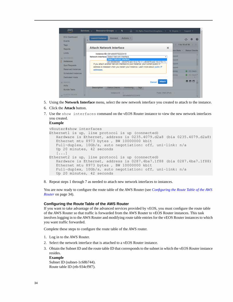
5. Using the Network Interface menu, select the new network interface you created to attach to the instance.
6. Click the Attach button.
7. Use the show interfaces command on the vEOS Router instance to view the new network interfacesyou created.Example
vRouter#show interfacesEthernet1 is up, line protocol is up (connected) Hardware is Ethernet, address is 0235.4079.d2a8 (bia 0235.4079.d2a8) Ethernet mtu 8973 bytes , BW 10000000 kbit Full-duplex, 10Gb/s, auto negotiation: off, uni-link: n/a Up 20 minutes, 42 seconds [...]Ethernet2 is up, line protocol is up (connected) Hardware is Ethernet, address is 0287.4ba7.1f88 (bia 0287.4ba7.1f88) Ethernet mtu 8973 bytes , BW 10000000 kbit Full-duplex, 10Gb/s, auto negotiation: off, uni-link: n/a Up 20 minutes, 42 seconds
8. Repeat steps 1 through 7 as needed to attach new network interfaces to instances.
You are now ready to configure the route table of the AWS Router (see Configuring the Route Table of the AWSRouter on page 34).
Configuring the Route Table of the AWS RouterIf you want to take advantage of the advanced services provided by vEOS, you must configure the route tableof the AWS Router so that traffic is forwarded from the AWS Router to vEOS Router instances. This taskinvolves logging in to the AWS Router and modifying route table entries for the vEOS Router instances to whichyou want traffic forwarded.
Complete these steps to configure the route table of the AWS router.
1. Log in to the AWS Router.
2. Select the network interface that is attached to a vEOS Router instance.
3. Obtain the Subnet ID and the route table ID that corresponds to the subnet in which the vEOS Router instanceresides.ExampleSubnet ID (subnet-1c68b744).Route table ID (rtb-934cf9f7).
34

4. Edit the route table entry so that it points to the corresponding interface of the vEOS Router in that subnet.ExampleTo reach any subnet other than 10.2.0.0/24, enter the “Target” to be the network interface ID of the locallyconnected interface of the vEOS Router.
5. (Optional) Repeat steps 2 through 4 to modify route table entries for additional vEOS Router instances.
You are now ready to configure the AWS CloudWatch Logs Agent (see Configuring the AWS CloudWatch LogsAgent on page 35). This ensures that vEOS Router logs are published to AWS.
Configuring the AWS CloudWatch Logs AgentThe AWS CloudWatch Logs Agent is the mechanism that publishes vEOS Router logs to AWS CloudWatch.Configuring the AWS CloudWatch Logs Agent ensures that the vEOS Router logs published to AWS CloudWatchconform to your requirements. The AWS CloudWatch Logs Agent is packaged with the awslogs.swix vEOSextension, which is installed and enabled by default whenever you launch vEOS Router instances through theAWS Marketplace.
Refer to the “AWS CloudWatch Quick Start Guide” to make sure that the vEOS Router instance has the rightcredentials for logging in to AWS.
Note: If you need to manually install or uninstall the awslogs.swix vEOS extension, seehttps://eos.arista.com/packaging-and-installing-eos-extensions/. If you need the awslogs.swix vEOSextension, contact Arista TAC.
Where to find vEOS Router logs
The location where vEOS Router logs are published to depends on your AWS CloudWatch Logs configuration.By default, the logs are located under "CloudWatch" "log group" name "veoslogs".
Modifying AWS log configuration
You can modify the AWS log configuration by:
• Editing configuration files under the /mnt/flash/awslogs/ directory.• Passing in instance user-data. Make sure you use the correct start and end markers, which are:
35
Using vEOS Router on the AWS Platform

%AWS-CONFIG-START%
#your configuration here
%AWS-CONFIG-END%
%AWSLOGS-CONFIG-START%
#your configuration here
%AWSLOGS-CONFIG-END%
%AWS-PROXY-START%
#your configuration here
%AWS-PROXY-END%
Note: You must restart awslogs using “sudo systemctl restart awslogs” under bash. The reconfigurationdoes not take effect until you restart awslogs.
vEOS Router log filenames
By default, the hostname of the vEOS Router instance is the filename of all vEOS Router logs for that instance.
Using User-data for Configuration of Entities and vEOS Router InstancesvEOS supports configuration of startup-config, AWS CloudWatch, and CloudHA through the use of user-data.Because user-data can be used to pass in configurations, Administrators can take advantage of this feature toquickly configure vEOS Router instances, AWS CloudWatch, and CloudHA.
Note: It is recommended that you test vEOS Router configurations on a vEOS Router or EOS devicebefore you use them to deploy a new vEOS Router.
Requirements for Uploading User-data
To ensure that the user-data is accepted on upload, make sure the user-data meets the following requirements:
• The configuration needs to be separated by start and end markers.• Markers are needed at the beginning of the line.• You must upload either text or configuration files (these are the types of files supported by vEOS Router).
EOS configuration for all interfaces can be passed in during deployment. The configuration will take effect asnew interfaces are attached to the vEOS Router.
List of Start and End Markers to Use
This table lists the start and end markers to use when configuring the EOS, AWS, Cloudwatch, and Cloud HAentities. For each specific entity, the configuration file and the location (file path) of the configuration file isgiven.
File PathMarkersEntity / Config File / Use
N/A%EOS-STARTUP-CONFIG-START%%
EOS-STARTUP-CONFIG-END%
Entity: EOS
File: EOS CLI configuration file
Use: Configure vEOS Router
36

/mnt/flash/awslogs/aws.conf%AWS-CONFIG-START%
%AWS-CONFIG-END%
Entity: AWS Logs
File: aws.conf
Use: Set up AWS region
/mnt/flash/awslogs/awsconf.conf%AWSLOGS-CONFIG-START%
%AWSLOGS-CONFIG-END%
Entity: AWS Logs
File: awslogs.conf
Use: Configure logging parameters
/mnt/flash/awslogs/proxy.conf%AWS-PROXY-START%
%AWS-PROXY-END%
Entity: AWS Logs
File: proxy.conf
Use: Configure proxy settings
/mnt/flash/cloud_ha_config.json%CLOUDHA-CONFIG-START%
%CLOUDHA-CONFIG-END%
Entity: Cloud HA
File: cloud_ha_config.json
Use: Configure vEOS Router for
High Availability
Sample Instance User-dataThe following sample user-data contains lines to startup the instance and to configure various entities.
The sample contains lines to configure:
• AWS CloudWatch logs (for the us-east-1 region)• AWS logging parameters• AWS proxy settings
Sample
%EOS-STARTUP-CONFIG-START%! EOS startup confighostname my-veosusername admin nopasswordusername admin sshkey file flash:key.pub%EOS-STARTUP-CONFIG-END%
%AWS-CONFIG-START%[plugins]cwlogs = cwlogs[default]region = us-east-1%AWS-CONFIG-END%
%AWSLOGS-CONFIG-END%[/var/log/messages]datetime_format = %b %d %H:%M:%Sfile = /var/log/messagesbuffer_duration = 5000log_group_name = veoslogslog_stream_name = {hostname}initial_position = start_of_file%AWSLOGS-CONFIG-END%
37
Using vEOS Router on the AWS Platform

%AWS-PROXY-START%HTTP_PROXY=http://<your_proxy>:<your_proxy_port>HTTPS_PROXY=http://<your_proxy>:<your_proxy_port>NO_PROXY=169.254.169.254%AWS-PROXY-END%
38

Chapter 5Using the vEOS Router on Microsoft Azure
The vEOS Router, which is based on the Arista EOS, runs as a virtual machine instance on Azure. Use the vEOSRouter to create the various types of virtual machine router instances you need for your Azure deployment. For example,edge routers and transit routers.
vEOS Router Image UpdatesThe process you use to update vEOS Router images is the standard update process used for EOS images.
For details on the steps to use, refer to the Arista EOS User Manual (seehttps://www.arista.com/en/support/product-documentation).
Supported Instance TypesWhen you launch vEOS Router instances, you must select an instance type. Make sure you select an instancetype that meets the resource requirements for the vEOS Router instance you are launching.
The Azure instance types supported by vEOS Router are:
• D2_v2 with 2 cores, 7.0GiB RAM, 2 NICs (High Bandwidth), and a 4GB OS disk.• D3_v2 with 4 cores, 14.0GiB RAM, 4 NICs (High Bandwidth), and a 4GB OS disk.• D4_v2 with 16 cores, 56.0GiB RAM, 8 NICs (High Bandwidth), and a 4GB OS disk.• D5_v2 with 16 cores, 56.0GiB RAM, 8 NICs (Extreme Bandwidth), and a 4GB OS disk.
Launching vEOS Router Azure InstancesThere are two methods which you can use to launch vEOS Router instances.
The methods are:
• Portal Marketplace: Instances are launched using the Azure Portal Marketplace.• Azure CLI 2.0: Instances are launched using a custom template through the Azure CLI 2.0. The primary
advantage of the method is the ability to include custom-data and customize your deployment.
To prevent conflicts in names, do not deploy the same template twice in the same resource group. To deploymultiple instances in the same resource group, modify the template so that all resources are renamed and all IPaddresses are unique.
39

Creating an Instance using the Portal MarketplaceTo create an instance using the Portal Marketplace, complete the following steps.
1. In the Azure portal, select the green '+' button in the top left of the screen.
2. In the search bar, type "Arista" and press enter.
3. Select the Arista offer you are interested in.
Figure 1: Arista selection
4. Select "Create".
Figure 2: Select "Create"
5. Fill out the required information and press "OK".
40

Figure 3: Required information
6. Configure the VNet and press "OK".
Figure 4: Configuring the VNet
7. Configure the subnets and press "OK".
41
Using the vEOS Router on Microsoft Azure

Figure 5: Configuring the subnets
8. Verify the information is correct and press "OK".
Figure 6: Verification
9. Read the Terms and Conditions, then press "Purchase".
42

Figure 7:Terms and Conditions
Creating Instances under Azure CLI 2.0To create vEOS Router instances under Azure CLI 2.0, complete the following steps.
1. Install Azure CLI 2.0 (https://docs.microsoft.com/en-us/cli/azure/install-azure-cli).
2. Run az login and follow the prompts to authorize the machine.
3. Download the template and parameters files from the GitHub repository.https://github.com/Azure/azure-quickstart-templates
4. Open the parameters file and specify the appropriate values. .
Note: If a different version of vEOS Router is required, the SKU can be modified in the parametersand template files.
5. (Optional) If you want to use custom-data, see vEOS Router Startup-Configuration using Instance Custom-Dataon page 45.
6. Use the template and parameters JSON files to launch the instance in Azure using the Azure CLI 2.0.
$ az group create --name ExampleGroup --location "Central US"
Note: You must use the same location as the storage account where the VHD image is uploaded.
$ az group deployment create \ --name ExampleDeployment \ --resource-group ExampleGroup \ --template-file <prefix>-template.json \ --parameters @<prefix>-parameters.json
Note: If you are using a newer version of the Azure CLI 2.0, you may encounter a parameter fileparsing bug. To fix this, remove the @ symbol before the parameters filename.
43
Using the vEOS Router on Microsoft Azure

Logging into InstanceTo log into an instance, complete the following steps.
1. Select the resource group containing your vEOS Router deployment from the Resource groups list.
2. Select the item publicIP.
3. Locate the IP address and DNS name found on the Overview page.
Note: If either of these fields is not populated, your instance still deploys. Refresh the page after a couple ofminutes.
4. Secure Shell (SSH) to your Virtual Machine (VM) using the IP address or Domain Name Server (DNS) namefound in the previous step, using the credentials you gave when you initially setup the VM.
bash# ssh [email protected]: *********
NOTE: It may take between 5-10 minutes for the instance to become reachable after the deployment starts.Refer to the section Troubleshooting Instance on page 46 for additional information.
44

vEOS Router Startup-Configuration using Instance Custom-DataDescribes launch employing custom-data information.
During the initial launching of the vEOS Router Instance, Azure provides a feature to upload custom-data. Theadministrator can upload vEOS Router configuration using custom-data at the time of the launching of the vEOSRouter Instance.
Custom-data can be used to pass in configuration for multiple entities. Currently, only the EOS configuration issupported in Azure. This configuration must be separated by start and end markers.
File PathMarkersEntity
N/A%EOS-STARTUP-CONFIG-START%%EOS-STARTUP-CONFIG-END%
EOS CLI configuration file
/mnt/flash/cloud_ha_config.json%CLOUDHA-CONFIG-START%%CLOUDHA-CONFIG-END%
CloudHA configuration file
Note the following regarding the custom-data.
• Markers must be at the beginning of the line.• The user is expected to have tested the configurations on a live system before using the configurations to deploy
the new vEOS Router. Mis-configuration may result in an unrecoverable instance.• EOS configuration for all interfaces can be passed in during deployment. The configuration takes effect as the
new instances attach to the vEOS Router.
Sample Instance Custom-DataThis is a sample of a configuration using custom-data.
%EOS-STARTUP-CONFIG-START%! EOS startup configusername admin nopasswordusername admin sshkey file flash:key.pub %EOS-STARTUP-CONFIG-END%
Providing Startup-Configuration using Azure Custom-DataAdding custom-data to an instance.
Currently, custom-data can only be used on instances deployed using the Azure CLI 2.0.
In order to add custom-data to an instance, the custom-data must be provided as a single-line value with '\n'delimiting newlines.
Use the single_line_json.sh script to convert your custom-data into this format.
#!/usr/bin/bash
cat $1 | python -c 'import json, sys; print( json.dumps( sys.stdin.read() ) )'
Usage of the script is as follows:
./single_line_json.sh user_data.txt
Copy and paste the generated output into the customData value field of the JSON parameters file.
45
Using the vEOS Router on Microsoft Azure

Troubleshooting InstanceTo troubleshoot the instance, complete the following steps.
1. Select the resource group containing your vEOS Router deployment from the Resource groups list.
2. Select the item vEOS Router.
Figure 8: Select the vEOS Router
3. Note the status of the VM. It should either be "Creating", "Starting", or "Running".
Figure 9: Status of the VM
4. Check the boot diagnostics for any error messages or warnings.
46

Figure 10: Error messages and warnings
ResourcesAdditional resources.
1. How To: Deploy Azure Virtual Machines With An Azure Resource Manager (ARM) Template -https://www.youtube.com/watch?v=wi74jR0MRLg
2. How To Deploy Resources -https://docs.microsoft.com/en-us/azure/azure-resource-manager/resource-group-template-deploy-cli
47
Using the vEOS Router on Microsoft Azure


Chapter 6Hypervisors
• Terminology on page 49• Minimum Server Requirements on page 49• Recommended Server Configuration Example on page 50• Supported Topologies on page 50
Terminology
• A server can be either a hardware or software entity.
• A hardware server is the physical computer that executes the virtual machine manager or hypervisor and all thevirtual machines. This is also known as the host machine.
• A software server is the hypervisor or virtual machine manager that hosts and manages the virtual machines. It isalso sometimes referred to as the host.
Minimum Server Requirements
VMware ESXi
x86-64 Server class CPU (32-bit CPUs are not supported) with:
• Ethernet NICs must be SR-IOV capable• BIOS / System Firmware support for SR-IOV• 8 GB free disk space• 16 GB RAM• 4 cores running a minimum 2.4GHz or greater and 16 GB memory• Intel VT-x and VT-d support
VMware ESXi SR-IOV based deployment
• Ethernet NICs must be SR-IOV capable• BIOS / System Firmware support for SR-IOV
KVM
vEOS is must be deployed on a x86-64 architecture server running KVM hypervisor. The minimum server requirementsfor KVM deployments are:
• 8 GB free disk space• 16 GB RAM• x86-64 Server class CPU (32-bit CPUs are not supported) with:
• Intel VT-x or AMD-V support for CPU Virtualization• Intel VT-d or AMD-IOMMU support for PCIe passthrough
49

• Intel AES-NI support• 4 cpu cores running at 2.4GHz.
KVM SR-IOV Based Deployment
• Ethernet NICs must be SR-IOV capable• BIOS / System Firmware support for SR-IOV
Recommended Server Configuration Example
The following is an example of a recommended server configuration for a production deployment. This serverconfiguration supports deployments in PCI-E passthrough or SR-IOV mode.
• Intel Xeon E5-2680 v3 single CPU socket based server platform.• 32 GB DDR4 1866 MHz DRAM• 64 GB free space on 7200 RPM hard disk or on a SSD• Intel x520 / 82599 based dual port 10G NIC card for packet forwarding
Supported Topologies
The following scenarios are describes in the Hypervisor Chapter
• Launching EXSi using vSphere Web Client• Launching vEOS on KVM with Linux bridge• Launching vEOS on KVM with SR-IOV• Launching vEOS on KVM with PCI-Passthrough
VMware ESXi Hypervisor
Launching VMware EXSi 6.0 and 6.5How to launch VMWare ESXi 6 and ESXi 6.5 for vEOS.
There are different ESXi user interfaces for managing the ESXi host, such as the vSphere Web Client and theESXi Web Client. The following task is required to launch VMware 6.0 and 6.5, and provides a general guidelineon the steps involved in deploying virtual machines with an OVF/OVA template.
Note: Arista supports only the Vsphere Web client, and suggests that you use the Vsphere Web client. The ESXi Web Client may have untested issues.
1. From the vCenter Server WEB-UI navigator, select Deploy OVF template.
50

2. Select the OVA file from the local machine.
3. Select the name and location for vEOS deployment.
51
Hypervisors

4. Select the host, cluster, resource pool or VAPP.
5. Verify the template details.
52

6. Select Thick provision eager zeroed from the datastore.
7. Select the default network.
53
Hypervisors

8. Complete the launch process.
7. Under the Recent Tasks tab at the bottom of the page, the progress of deployment will be displayed. Oncethe deployment is complete, power on the machine.
54

KVMThis section describes the system requirements, installation and configuration procedures for vEOS.
Server
A server can be either a hardware or software entity.
A hardware server is the physical computer that executes the virtual machine manager or hypervisor and all thevirtual machines. This is also known as the host machine.
A software server is the hypervisor or virtual machine manager that hosts and manages the virtual machines. Itis also sometimes referred to as the host. In this document specifically, the software server is comprised ofRedHat Linux with virtualization support (KVM).
System RequirementsKVM (Kernel-based Virtual Machine) is a full virtualization solution for Linux on x86 hardware containingvirtualization extensions.
vEOS is part of the Arista EOS that allows it to be deployed as a virtual machine image. This document detailsthe system requirements of vEOS on Linux KVM based hypervisors.
Minimum Server Requirements
• Intel x86• 4 cores running at 2.4GHz or greater• 16 GB memory• Intel VT-d support• For SR-IOV based deployment, the NICs need to be SR-IOV capable
55
Hypervisors

Hypervisor support
• RedHat 7 with virtualization support. Please see below for virtualization https://wiki.centos.org/HowTos/KVM.Make sure libvirt is installed by executing virsh list which should return without errors. Python 2.7+ is neededto run the installation script vSphere 5.5 and 6.0.
Supported Images
DetailsFile NameImage Name
Image Hard Disk that contains vEOS. This
file can grow as agents in vEOS generates
logs/traces, etc.
EOS.ovaKVM vEOS image
Using Libvirt to Manage vEOS VM on KVMLibvirt is a open source library which provides vEOS management of Virtual Machines.
Libvirt supports many function such as creation, update, and deletion and of VMs.
The complete Libvirt command reference can be found at http://libvirt.org/virshcmdref.html
Define a new VMDefine a domain from an XML file, by using the virsh define <vm-definition-file.xml > command. This willdefine the domain, but it does not start the domain.
The definition file has vm-name, CPU, memory, network connectivity, and path to the image. The parameterscan be found at https://libvirt.org/formatdomain.html. There is a sample vEOS file in the example below.
Undefine the Inactive Domain
Undefine the configuration for the inactive domain by using the virsh undefine <vm-name> and specifying itsdomain name.
Start VM
Start a previously defined or inactive domain by using the virsh start <vm-name> command.
Stop VM
Terminate a domain immediately by using the virsh destroy <vm-name> command
Managing Networks
The xml definition format for networks is defined at https://libvirt.org/formatnetwork.html. These commandsare similar to the VM, but with a prefix 'net-' :
The virsh net-define <network-definition-file.xml> command
The virsh net-undefine network-name command removes an inactive virtual network from the libvirtconfiguration.
The virsh start network-name command manually starts a virtual network that isn't running.
The virsh destroy network-name command shuts down a running virtual network.
Launching vEOS in LinuxBridge ModeSetup steps for LinuxBridges so vEOS can connect to the right networks when installed.
56

• Example Deployment on page 57• Setting up the Mode on page 57
Example Deployment
vEOS can employ para-virtualized network I/O interfaces, which in Linux KVM is also known as Virtio . EachNIC is connected to a unique underlying Linux layer-2 bridge in the hypervisor which in-turn provides accessto an uplink.
In this example,
• Ethernet1 is connected to the physical ethernet port connected to the WAN through a LinuxBridge. Router isconfigured with a WAN IP address on this port.
• Ethernet2 is connected to the physical ethernet port connected to the LAN through a LinuxBridge.• Server IP address in the diagram is assumed to be configured on the LAN Linuxbridge device.
Note: Arista recommends using Ethernet1 for WAN and Ethernet2 for LAN, however any vEOS port can beused.
Setting up the Mode
Use the script SetupLinuxBridge.pyc usage python SetupLinuxBridge.pyc <bridge- name>
Cut and paste the following xml template into a file (veos.xml) and customize the elements bolded below.
• virsh define <veos define file say veos.xml>• virsh start <veos-name>• virsh console <veos-name>
<domain type='kvm'><!-- veos name, cpu and memory settings -->
57
Hypervisors

<name>kvs1-veos1</name><memory unit='MiB'>4096</memory><currentMemory unit='MiB'>4096</currentMemory><vcpu placement='static'>2</vcpu><resource><partition>/machine</partition></resource><cpu mode='host-model'/><os><type arch='x86_64’>hvm</type><boot dev='cdrom'/><boot dev='hd'/></os><features><acpi/><apic/><pae/></features><clock offset='utc'/><on_poweroff>destroy</on_poweroff><on_reboot>restart</on_reboot><on_crash>restart</on_crash><devices><emulator>/usr/bin/qemu-system-x86_64</emulator><disk type='file' device='disk'><driver name='qemu' type='qcow2' cache='directsync'/><source file="/path-to-veos-image/EOS.qcow2"/><target dev='hda' bus='ide'/><alias name='ide0-0-0'/><address type='drive' controller='0' bus='0' target='0' unit='0'</disk><disk type='file' device='cdrom'><driver name='qemu' type='raw'/><source file="/path-to-aboot-image/Aboot-veos-serial.iso"/><target dev='hdc' bus='ide'/>
<readonly/><alias name='ide0-1-0'/><address type='drive' controller='0' bus='1' target='0' unit='0'</disk><controller type='usb' index='0'><alias name='usb0'/><address type='pci' domain='0x0000' bus='0x00' slot='0x01' function='0</controller><controller type='pci' index='0' model='pci-root'><alias name='pci0'/></controller><controller type='ide' index='0'><alias name='ide0'/><address type='pci' domain='0x0000' bus='0x00' slot='0x01' funct</controller><!-- In this case management is connected to linux bridge --><interface type='bridge'><source bridge='brMgmt'/><model type='virtio'/><address type='pci' domain='0x0000' bus='0x00' slot='0x03' funct</interface><serial type='pty'><source path='/dev/pts/4'/><target port='0'/><alias name='serial0'/>
58

<target port='0'/><alias name='serial0'/></serial><console type='pty' tty='/dev/pts/4'><source path='/dev/pts/4'/><target type='serial' port='0'/><alias name='serial0'/></console><input type='mouse' bus='ps2'/><graphics type='vnc' port='5903' autoport='yes' listen='127.0.0.1'<listen type='address' address='127.0.0.1'/></graphics><video><model type='cirrus' vram='9216' heads='1'/><alias name='video0'/><address type='pci' domain='0x0000' bus='0x00' slot='0x02' funct</video><memballoon model='virtio'><alias name='balloon0'/><address type='pci' domain='0x0000' bus='0x00' slot='0x04' funct</memballoon><!-- Has two data ports on different vlansCut and paste the more interface elements for more interfaces but increment the slot number. Note that brWAN and brLAN bridges need to be created beforehand --><interface type='bridge'><source bridge='brWAN'/><model type='virtio'/><address type='pci' domain='0x0000' bus='0x00' slot='5' function</interface><interface type='bridge'><source bridge='brLAN'/><model type='virtio'/><address type='pci' domain='0x0000' bus='0x00' slot='6' function</interface></devices></domain>
<!-- veos name, cpu and memory settings --><name>kvs1-veos1</name><memory unit='MiB'>4096</memory><currentMemory unit='MiB'>4096</currentMemory><vcpu placement='static'>2</vcpu><resource><partition>/machine</partition></resource><cpu mode='host-model'/><os><type arch='x86_64’>hvm</type><boot dev='cdrom'/><boot dev='hd'/></os><features><acpi/><apic/><pae/></features><clock offset='utc'/><on_poweroff>destroy</on_poweroff><on_reboot>restart</on_reboot><on_crash>restart</on_crash>
59
Hypervisors

<devices><emulator>/usr/bin/qemu-system-x86_64</emulator><disk type='file' device='disk'><driver name='qemu' type='qcow2' cache='directsync'/><source file="/path-to-veos-image/EOS.qcow2"/><target dev='hda' bus='ide'/><alias name='ide0-0-0'/><address type='drive' controller='0' bus='0' target='0' unit='0'</disk><disk type='file' device='cdrom'><driver name='qemu' type='raw'/><source file="/path-to-aboot-image/Aboot-veos-serial.iso"/><target dev='hdc' bus='ide'/>
<readonly/><alias name='ide0-1-0'/><address type='drive' controller='0' bus='1' target='0' unit='0'</disk><controller type='usb' index='0'><alias name='usb0'/><address type='pci' domain='0x0000' bus='0x00' slot='0x01' function='0</controller><controller type='pci' index='0' model='pci-root'><alias name='pci0'/></controller><controller type='ide' index='0'><alias name='ide0'/><address type='pci' domain='0x0000' bus='0x00' slot='0x01' funct</controller><!-- In this case management is connected to linux bridge --><interface type='bridge'><source bridge='brMgmt'/><model type='virtio'/><address type='pci' domain='0x0000' bus='0x00' slot='0x03' funct</interface><serial type='pty'><source path='/dev/pts/4'/><target port='0'/><alias name='serial0'/><target port='0'/><alias name='serial0'/></serial><console type='pty' tty='/dev/pts/4'><source path='/dev/pts/4'/><target type='serial' port='0'/><alias name='serial0'/></console><input type='mouse' bus='ps2'/><graphics type='vnc' port='5903' autoport='yes' listen='127.0.0.1'<listen type='address' address='127.0.0.1'/></graphics><video><model type='cirrus' vram='9216' heads='1'/><alias name='video0'/><address type='pci' domain='0x0000' bus='0x00' slot='0x02' funct</video><memballoon model='virtio'><alias name='balloon0'/><address type='pci' domain='0x0000' bus='0x00' slot='0x04' funct</memballoon><!-- Has two data ports on different vlans
60

Cut and paste the more interface elements for more interfaces but increment the slot number.Note that brWAN and brLAN bridges need to be created beforehand --><interface type='bridge'><source bridge='brWAN'/><model type='virtio'/><address type='pci' domain='0x0000' bus='0x00' slot='5' function</interface><interface type='bridge'><source bridge='brLAN'/><model type='virtio'/><address type='pci' domain='0x0000' bus='0x00' slot='6' function</interface></devices></domain>
Launching vEOS in SR-IOV ModeSingle Root I/O Virtualization (SR-IOV) allows a single PCIe physical device under a single root port to appearto be multiple physical devices to the hypervisor .
• Launching SR-IOV on page 61• Setting Up the Host for Single Root I/O Virtualization (SR-IOV) on page 62
Launching SR-IOV
vEOS can also use PCIE SRI-OV I/O interfaces. Each SRI-OV NIC is passed-through to the VM such thatnetwork I/O does not hit the hypervisor. In this model, the hypervisor and multiple VMs can share the same NICcard.
SR-IOV has the following advantages over LinuxBridge:
• Higher Performance ~ 2x• Better latency and jitter characteristics• vEOS directly receives physical port state indications from the virtual device.• Using SR-IOV virtualize the NIC.• The NICs have a built-in bridge to do basic bridging.• Avoids software handling of the packets in the kernel.
61
Hypervisors

Setting Up the Host for Single Root I/O Virtualization (SR-IOV)
The following tasks are required to set up the host for SR-IOV.
1. Verify the IOMMU Support
Use the virt-host-validate Linux command to check IOMMU (input/output memory management unit)support. If it does not "PASS" for IOMMU, check the BIOS setting and kernel settings.
The example below is what should be displayed.
[arista@solution]$ virt-host-validate QEMU: Checking for device assignment IOMMU support : PASS QEMU: Checking if IOMMU is enabled by kernel : PASS
2. Verify the Drivers are Supported
Ensure the PCI device with SR-IOV capabilities is detected. In the example below, an INTEL 82599ES networkinterface card is detected which supports SR-IOV.
Verify the ports and NIC IDs that are bolded in the lspci | grep Ethernet Linux command outputbelow.
# lspci | grep Ethernet01:00.0 Ethernet controller: Intel Corporation I350 Gigabit Network Connection (rev 01)01:00.1 Ethernet controller: Intel Corporation I350 Gigabit Network Connection (rev 01)
62

01:00.2 Ethernet controller: Intel Corporation I350 Gigabit Network Connection (rev 01)01:00.3 Ethernet controller: Intel Corporation I350 Gigabit Network Connection (rev 01)81:00.0 Ethernet controller: Intel Corporation I350 Gigabit Network Connection (rev 01)81:00.1 Ethernet controller: Intel Corporation I350 Gigabit Network Connection (rev 01)81:00.2 Ethernet controller: Intel Corporation I350 Gigabit Network Connection (rev 01)81:00.3 Ethernet controller: Intel Corporation I350 Gigabit Network Connection (rev 01)82:00.0 Ethernet controller: Intel Corporation 82599ES 10-Gigabit SFI/SFP+ Network Connection (rev 01)82:00.1 Ethernet controller: Intel Corporation 82599ES 10-Gigabit SFI/SFP+ Network Connection (rev 01)83:00.0 Ethernet controller: Intel Corporation 82599ES 10-Gigabit SFI/SFP+ Network Connection (rev 01)83:00.1 Ethernet controller: Intel Corporation 82599ES 10-Gigabit SFI/SFP+ Network Connection (rev 01)
3. Verify the Driver Kernel is Active
After you have confirmed the device is supported, the driver kernel module should load automatically by thekernel. To verify the driver kernel is active, use thelsmod | grep igbLinux command.
[root@kvmsolution]# lsmod | grep igbigb 197328 0ptp 19231 2 igb,ixgbedca 15130 2 igb,ixgbei2c_algo_bit 13413 2 ast,igbi2c_core 40756 6 ast,drm,igb,i2c_i801,drm_kms_helper,i2c_algo_bit
4. Activate Virtual Functions (VFs).
The maximum number of virtual functions supported depends on the type of card. The example below showsthat the PF identifier 82:00.0 supports a total of 63 VFs.
[arista@localhost]$ cat/sys/bus/pci/devices/0000\:82\:00.0/sriov_totalvfs 63
To activate the 7 VFs per PFs and make them persistent after reboot, add the line options igb max_vfs=7 inixgbe.conf and the sriov.conf files in /etc/modprobe.d
Use the rmmod ixgbe and modprobe ixgbe Linux commands to unload and reload the module.
5. Verify the VFs are Detected
Verify the VFs are detected by using the lspci | grep Ethernet Linux command. For the two identifiers82:00.0 & 82:00.1, 14 VFs are detected.
# lspci | grep Ethernet82:00.0 Ethernet controller: Intel Corporation 82599ES 10-Gigabit SFI/SFP+ Network Connection (rev 01)82:00.1 Ethernet controller: Intel Corporation 82599ES 10-Gigabit SFI/SFP+ Network Connection (rev 01)82:10.0 Ethernet controller: Intel Corporation 82599 Ethernet Controller Virtual Function (rev 01)82:10.1 Ethernet controller: Intel Corporation 82599 Ethernet Controller Virtual Function (rev 01)82:10.2 Ethernet controller: Intel Corporation 82599 Ethernet Controller Virtual Function (rev 01)
63
Hypervisors

82:10.3 Ethernet controller: Intel Corporation 82599 Ethernet Controller Virtual Function (rev 01)82:10.4 Ethernet controller: Intel Corporation 82599 Ethernet Controller Virtual Function (rev 01)82:10.5 Ethernet controller: Intel Corporation 82599 Ethernet Controller Virtual Function (rev 01)82:10.6 Ethernet controller: Intel Corporation 82599 Ethernet Controller Virtual Function (rev 01)82:10.7 Ethernet controller: Intel Corporation 82599 Ethernet Controller Virtual Function (rev 01)82:11.0 Ethernet controller: Intel Corporation 82599 Ethernet Controller Virtual Function (rev 01)82:11.1 Ethernet controller: Intel Corporation 82599 Ethernet Controller Virtual Function (rev 01)82:11.2 Ethernet controller: Intel Corporation 82599 Ethernet Controller Virtual Function (rev 01)82:11.3 Ethernet controller: Intel Corporation 82599 Ethernet Controller Virtual Function (rev 01)82:11.4 Ethernet controller: Intel Corporation 82599 Ethernet Controller Virtual Function (rev 01)82:11.5 Ethernet controller: Intel Corporation 82599 Ethernet Controller Virtual Function (rev 01)
6. Locate the Serial Numbers for the PFs and VRFs
Locate the serial numbers for the PFs and VFs. The Linux virsh nodedev-list | grep 82 commandbelow displays the serial number for identifiers 82:00.0 & 82:00.1 . The first two numbers are the serial numbersfor the PFs and the remaining are the serial numbers for the VFs.
# virsh nodedev-list | grep 82pci_0000_82_00_0pci_0000_82_00_1pci_0000_82_10_0pci_0000_82_10_1pci_0000_82_10_2pci_0000_82_10_3pci_0000_82_10_4pci_0000_82_10_5pci_0000_82_10_6pci_0000_82_10_7pci_0000_82_11_0pci_0000_82_11_1pci_0000_82_11_2pci_0000_82_11_3pci_0000_82_11_4pci_0000_82_11_5
7. Select the Serial Number of the VF
Select the serial number of the VF that will be attached to the VM (vEOS). Using the Linux virshnodedev-dumpxml <serial number> command, locate the bus , slot and function parameters. Forexample, serial number: pci_0000_82_11_1 displays the following details.
# virsh nodedev-dumpxml pci_0000_82_11_1<device> <name>pci_0000_82_11_1</name> <path>/sys/devices/pci0000:80/0000:80:02.0/0000:82:11.1</path> <parent>computer</parent> <driver> <name>ixgbevf</name> </driver> <capability type='pci'>
64
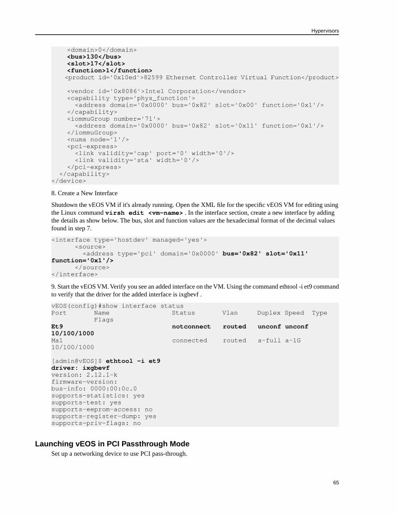
<domain>0</domain><bus>130</bus>
<slot>17</slot> <function>1</function> <product id='0x10ed'>82599 Ethernet Controller Virtual Function</product>
<vendor id='0x8086'>Intel Corporation</vendor> <capability type='phys_function'> <address domain='0x0000' bus='0x82' slot='0x00' function='0x1'/> </capability> <iommuGroup number='71'> <address domain='0x0000' bus='0x82' slot='0x11' function='0x1'/> </iommuGroup> <numa node='1'/> <pci-express> <link validity='cap' port='0' width='0'/> <link validity='sta' width='0'/> </pci-express> </capability></device>
8. Create a New Interface
Shutdown the vEOS VM if it's already running. Open the XML file for the specific vEOS VM for editing usingthe Linux command virsh edit <vm-name> . In the interface section, create a new interface by addingthe details as show below. The bus, slot and function values are the hexadecimal format of the decimal valuesfound in step 7.
<interface type='hostdev' managed='yes'> <source> <address type='pci' domain='0x0000' bus='0x82' slot='0x11' function='0x1'/> </source></interface>
9. Start the vEOS VM. Verify you see an added interface on the VM. Using the command ethtool -i et9 commandto verify that the driver for the added interface is ixgbevf .
vEOS(config)#show interface statusPort Name Status Vlan Duplex Speed Type FlagsEt9 notconnect routed unconf unconf 10/100/1000Ma1 connected routed a-full a-1G 10/100/1000
[admin@vEOS]$ ethtool -i et9driver: ixgbevfversion: 2.12.1-kfirmware-version:bus-info: 0000:00:0c.0supports-statistics: yessupports-test: yessupports-eeprom-access: nosupports-register-dump: yessupports-priv-flags: no
Launching vEOS in PCI Passthrough ModeSet up a networking device to use PCI pass-through.
65
Hypervisors
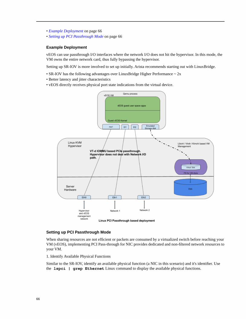
• Example Deployment on page 66• Setting up PCI Passthrough Mode on page 66
Example Deployment
vEOS can use passthrough I/O interfaces where the network I/O does not hit the hypervisor. In this mode, theVM owns the entire network card, thus fully bypassing the hypervisor.
Setting up SR-IOV is more involved to set up initially. Arista recommends starting out with LinuxBridge.
• SR-IOV has the following advantages over LinuxBridge Higher Performance ~ 2x• Better latency and jitter characteristics• vEOS directly receives physical port state indications from the virtual device.
Setting up PCI Passthrough Mode
When sharing resources are not efficient or packets are consumed by a virtualized switch before reaching yourVM (vEOS), implementing PCI Pass-through for NIC provides dedicated and non-filtered network resources toyour VM.
1. Identify Available Physical Functions
Similar to the SR-IOV, identify an available physical function (a NIC in this scenario) and it's identifier. Usethe lspci | grep Ethernet Linux command to display the available physical functions.
66

In this example, 82:00.0 Ethernet controller: Intel Corporation 82599ES 10-Gigabit SFI/SFP+ Network Connectionis the physical function and 82:00.0 is the device identification code.
# lspci | grep Ethernet01:00.0 Ethernet controller: Intel Corporation I350 Gigabit Network Connection (rev 01)01:00.1 Ethernet controller: Intel Corporation I350 Gigabit Network Connection (rev 01)01:00.2 Ethernet controller: Intel Corporation I350 Gigabit Network Connection (rev 01)01:00.3 Ethernet controller: Intel Corporation I350 Gigabit Network Connection (rev 01)81:00.0 Ethernet controller: Intel Corporation I350 Gigabit Network Connection (rev 01)81:00.1 Ethernet controller: Intel Corporation I350 Gigabit Network Connection (rev 01)81:00.2 Ethernet controller: Intel Corporation I350 Gigabit Network Connection (rev 01)81:00.3 Ethernet controller: Intel Corporation I350 Gigabit Network Connection (rev 01)82:00.0 Ethernet controller: Intel Corporation 82599ES 10-Gigabit SFI/SFP+ Network Connection (rev 01)82:00.1 Ethernet controller: Intel Corporation 82599ES 10-Gigabit SFI/SFP+ Network Connection (rev 01)83:00.0 Ethernet controller: Intel Corporation 82599ES 10-Gigabit SFI/SFP+ Network Connection (rev 01)83:00.1 Ethernet controller: Intel Corporation 82599ES 10-Gigabit SFI/SFP+ Network Connection (rev 01)
2. Verify Available Physical Functions
Verify the available physical functions by using the virsh Linux commands
[arista@solution]$ virsh nodedev-list | grep 82_00_0pci_0000_82_00_0[arista@solution]$ virsh nodedev-dumpxml pci_0000_82_00_0<device> <name>pci_0000_82_00_0</name> <path>/sys/devices/pci0000:80/0000:80:02.0/0000:82:00.0</path> <parent>pci_0000_80_02_0</parent> <driver> <name>vfio-pci</name> </driver> <capability type='pci'>
<domain>0</domain><bus>130</bus>
<slot>0</slot> <function>0</function> <product id='0x10fb'>82599ES 10-Gigabit SFI/SFP+ Network Connection</product> <vendor id='0x8086'>Intel Corporation</vendor> <capability type='virt_functions' maxCount='64'/>
In this example, the domain is 0 (Hex domain=0x0), bus is 130 (Hex bus=0x82) , slot is 0 (Hex slot=0x0), andfunction is 0 (Hex function=0x0).
With the domain, bus, slot, and function information, construct the device entry and add it into your VM's XMLconfiguration.
<devices> ...
<hostdev mode='subsystem' type='pci' managed='yes'>
67
Hypervisors
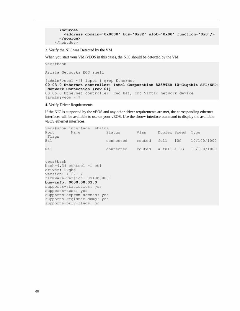
<source> <address domain='0x0000' bus='0x82' slot='0x00' function='0x0'/> </source> </hostdev>
3. Verify the NIC was Detected by the VM
When you start your VM (vEOS in this case), the NIC should be detected by the VM.
veos#bash
Arista Networks EOS shell
[admin@veos1 ~]$ lspci | grep Ethernet00:03.0 Ethernet controller: Intel Corporation 82599EB 10-Gigabit SFI/SFP+ Network Connection (rev 01)00:05.0 Ethernet controller: Red Hat, Inc Virtio network device[admin@veos ~]$
4. Verify Driver Requirements
If the NIC is supported by the vEOS and any other driver requirements are met, the corresponding ethernetinterfaces will be available to use on your vEOS. Use the shouw interface command to display the availablevEOS ethernet interfaces.
veos#show interface status Port Name Status Vlan Duplex Speed Type FlagsEt1 connected routed full 10G 10/100/1000
Ma1 connected routed a-full a-1G 10/100/1000
veos#bashbash-4.3# ethtool -i et1driver: ixgbeversion: 4.2.1-kfirmware-version: 0x18b30001bus-info: 0000:00:03.0supports-statistics: yessupports-test: yessupports-eeprom-access: yessupports-register-dump: yessupports-priv-flags: no
68

Chapter 7IPsec Support
vEOS Router provides robust support for the use of IPsec to establish and maintain IPsec tunnels for secure (encrypted)communications between virtual router peer instances.
vEOS Router supports the use of IPsec to:
• Secure communications between vEOS Router instances.• Secure communications between vEOS Router instances and non-Arista virtual router instances.
Note: For the latest information on the types of virtual routers that can share IPsec tunnels with vEOS Router,see the vEOS Router Release Notes.
Supported Tunnel TypesvEOS Router supports the use of two basic types of IPsec tunnels. The tunnel types are determined based on theencapsulation mode.
The supported tunnel types are:
DescriptionType
In GRE-over-IPsec encapsulation mode, the application payload is first encapsulated within a GRE packet. The
GRE packet is then encrypted by IPsec, which results in the packet being encapsulated and encrypted by the
IPsec header.
GRE-over-IPsec
You select this encapsulation type by specifying “tunnel mode gre” for the tunnel interface to which the IPsec
profile is being applied. This ensures that packets forwarded on the interface are encrypted.
When using GRE-over-IPsec encapsulation mode, both IPsec mode options are supported (you can select either
"transport" or "tunnel").
In VTI encapsulation mode, the application payload is directly encapsulated and encrypted by the IPsec header.VTI IPsec
You select this encapsulation type by specifying “tunnel mode ipsec” for the tunnel interface to which the IPsec
profile is being applied. This ensures that packets forwarded on the interface are encrypted.
When using VTI encapsulation mode, IPsec mode must be set to "transport". You cannot use "tunnel" for IPsec
mode.
69

Requirements When Using NATvEOS Router supports the use of NAT-Traversal to communicate with the remote peer virtual router. To ensurethat the tunnel configuration between the vEOS Router and peer router is successful, make sure that vEOS Routertunnel configuration meets the requirements for using NAT.
The requirements are:
• Configure the "tunnel source" so that it uses the IP address of the tunnel interface of the underlay network (thephysical network).
• Configure the "local identification" to use the public IP address of the corresponding tunnel source. Youconfigure the "local identification" using the local-id command when creating the IKE policy.
Using IPsec on vEOS Router Instances
vEOS Router enables you to establish and maintain GRE-over-IPsec and VTI IPsec tunnels for secure (encrypted)communications between peer vEOS Router instances.
TopologyvEOS Router can be used to establish and maintain IPsec tunnels between peer EOS Router instances in differenttopologies of varying complexity.
The following diagram represents a basic IPsec tunnel configuration in which vEOS Router instances areconnected using an IPsec tunnel.
Configuring IPsec Tunnels on vEOS Router InstancesUse this procedure to configure GRE-over-IPsec or VTI IPsec tunnels on peer vEOS Router instances. The peerinstances can reside in different VPCs or VNETs, or the same VPC or VNET.
The procedure provides all of the steps required to set up either GRE-over-IPsec or VTI IPsec tunnels. Most ofthe steps are the same for both tunnel types (steps 1 through 7 are the same). Step 8 is the step in which you mustchoose the tunnel type.
Note: vEOS Router by default uses IKE version 2 for all IPsec tunnels. If you want to configure a tunnelthat uses IKE version 1, you must explicitly configure the vEOS Router to use IKE version 1.
High Throughput Option
70

To achieve high throughput over an IPsec connection, enable the IPsec flow parallelization feature. When thefeature is enabled, multiple cores are used to parallelize the IPsec encryption and decryption processing. Toenable the feature, include the flow parallelization encapsulation udp command to in the IPsecprofile configuration.
Note: You must enable the feature on both ends of the tunnel.
If the IPsec session is established without the feature enabled, you must do the following:
• Under the IPsec profile for the tunnel, use the flow parallelization encapsulation udp commandto enable the feature.
• Shutdown the tunnel on the tunnel interface.• Bring the tunnel back up on the tunnel interface. After it is up, the feature should be enabled.
Procedure
Complete the following steps to configure GRE-over-IPsec or VTI IPsec tunnels on vEOS Router instances.
1. (Complete this step only if you want to use IKE version 1. Skip this step and go directly to step 2 to use IKEversion 2, which is the default.)
vRouter(config)#ip securityvRouter(config-ipsec)#ike policy ike-peerRtrvRouter(config-ipsec-ike)#version 1
2. Use this command to enter IP security mode.
vrouter(config)# ip security
3. Create an IKE Policy to be used to communicate with the peer to establish IKE Phase 1. You have the optionof configuring multiple IKE policies.
The default IKE Policy values are:
• Encryption - AES256• Integrity - SHA256• DH group - Group 14• IKE lifetime - 8 hours
Example:
vrouter(config-ipsec)# ike policy ike-vrouter vrouter(config-ipsec-ike)# encryption aes256 vrouter(config-ipsec-ike)# integrity sha256 vrouter(config-ipsec-ike)# dh-group 24vrouter(config-ipsec-ike)# version 2 vrouter(config-ipsec-ike)# exitvrouter(config-ipsec)# ike policy ike-default vrouter(config-ipsec-ike)# version 2 vrouter(config-ipsec-ike)# exit
4. If the router is behind a NAT, configure the local-id with the local public IP address.Example:
vrouter(config-ipsec-ike)#local-id <public ip address>
5. Create an IPsec Security Association policy to be used in the data path for encryption and integrity. Youhave the option of enabling Perfect Forward Secrecy by configuring a DH group to the SA.
71
IPsec Support

Example: In this example, AES256 is used for encryption, SHA 256 is used for integrity, and Perfect ForwardSecrecy is enabled (the DH group is 14).
vrouter(config-ipsec)# sa policy sa-vrouter vrouter(config-ipsec-sa)# esp encryption aes256 vrouter(config-ipsec-sa)# esp integrity sha256 vrouter(config-ipsec-sa)# pfs dh-group 14 vrouter(config-ipsec-sa)# sa lifetime 2 vrouter(config-ipsec-sa)# exit
vrouter(config-ipsec)# sa policy sa-default vrouter(config-ipsec-sa)# exit
6. Bind (associate) the IKE and SA policies together using an IPsec profile. You must provide a shared-key,which should be common on both peers. (The default profile assigns default values for all parameters thatare not explicitly configured in the other profiles.)Example: In this example, tunnel mode is set to Transport. The IKE Policy ike-peerRtr and SA Policysa-peerRtr are applied to profile peer-Rtr. Dead Peer Detection is enabled and configured to delete theconnection when the peer is down for more than 50 seconds. The peer (peer-Rtr) is set to be the responder.
vrouter(config-ipsec)# profile defaultvrouter(config-ipsec-profile)# ike-policy ikedefaultvrouter(config-ipsec-profile)# sa-policy sadefaultvrouter(config-ipsec-profile)# shared-key aristavrouter(config-ipsec)# profile peer-Rtrvrouter(config-ipsec-profile)# ike-policy ike-peerRtrvrouter(config-ipsec-profile)# sa-policy sa-peerRtrvrouter(config-ipsec-profile)# dpd 10 50 clearvrouter(config-ipsec-profile)# connection addvrouter(config-ipsec-profile)# mode transport
7. Configure the WAN interface to be the underlying interface for the tunnel. You must specify an L3 addressfor the tunnel. If you do not, the vEOS Router cannot route packets using the tunnel.Example:
vrouter(config)# interface Et1 vrouter(config-if-Et1)# no switchportvrouter(config-if-Et1)# ip address 1.0.0.1/24 vrouter(config-if-Et1)# mtu 1500
8. Apply the IPsec profile to a new tunnel interface. You create the new tunnel interface as part of this step.You can choose to configure the tunnel as a GRE-over-IPsec tunnel, or a VTI IPsec tunnel.Example (GRE-over-IPsec): In this example, the new tunnel interface is Tunnel0. The new tunnel interfaceis configured to use IPsec, and the tunnel mode is set to GRE. The other end of the tunnel also needs to beconfigured as a GRE-over-IPsec tunnel.
vrouter(config)# interface tunnel0vrouter(config-if-Tu0)#ip address 1.0.3.1/24 vrouter(config-if-Tu0)#tunnel mode gre vrouter(config-if-Tu0)#mtu 1400vrouter(config-if-Tu0)#tunnel source 1.0.0.1vrouter(config-if-Tu0)#tunnel destination 1.0.0.2 vrouter(config-if-Tu0)#tunnel ipsec profile vrouter
Example (VTI IPsec): To configure a VTI IPsec tunnel, you need to set the tunnel mode to tunnel modeipsec. The other tunnel element settings are the same as the settings for GRE-over-IPsec.
vrouter(config)# interface tunnel0vrouter(config-if-Tu0)#ip address 1.0.3.1/24 vrouter(config-if-Tu0)#tunnel mode ipsecvrouter(config-if-Tu0)#mtu 1400vrouter(config-if-Tu0)#tunnel source 1.0.0.1
72

vrouter(config-if-Tu0)#tunnel destination 1.0.0.2 vrouter(config-if-Tu0)#tunnel ipsec profile vrouter
9. Create the GRE-over-IPsec tunnel interface in a VRF using the vrf forwarding command. Create theVRF (if needed), and then create the GRE tunnel interface and configure it. Make sure you specify the tunnelkey that is unique across all tunnels.
Note: If tunnels in different VRFs need to share the IPsec connection, specify the same source,destination, and ipsec profile.
Example:
vrouter(config)# vrf definition redvrouter(config-vrf-red)#rd 1:3 vrouter(config-vrf-red)# interface tunnel0 vrouter(config-if-Tu0)#ip address 1.0.3.1/24 vrouter(config-if-Tu0)#vrf forwarding red vrouter(config-if-Tu0)#tunnel mode gre vrouter(config-if-Tu0)#mtu 1400vrouter(config-if-Tu0)#tunnel source 1.0.0.1vrouter(config-if-Tu0)#tunnel destination 1.0.0.2vrouter(config-if-Tu0)#tunnel key 100 vrouter(config-if-Tu0)#tunnel ipsec profile vrouter
vrouter(config)# vrf definition blue vrouter(config-vrf-blue)#rd 1:4 vrouter(config-vrf-blue)# interface tunnel1 vrouter(config-if-Tu1)#ip address 1.0.4.1/24 vrouter(config-if-Tu1)#vrf forwarding blue vrouter(config-if-Tu1)#tunnel mode gre vrouter(config-if-Tu1)#mtu 1400vrouter(config-if-Tu1)#tunnel source 1.0.0.1vrouter(config-if-Tu1)#tunnel destination 1.0.0.2vrouter(config-if-Tu1)#tunnel key 200 vrouter(config-if-Tu1)#tunnel ipsec profile vrouter
10. (Optional) Enable the IPsec flow parallelization feature to achieve high throughput over the IPsec tunnel. Toenable the feature, include the flow parallelization encapsulation udp command in the IPsec profileconfiguration. Then, apply the IPsec profile configuration to the tunnel interface.Example: (IPsec profile configuration)
vrouter(config-ipsec)# profile vroutervrouter(config-ipsec-profile)# ike-policy ike-vroutervrouter(config-ipsec-profile)# sa-policy sa-vroutervrouter(config-ipsec-profile)# dpd 10 50 clearvrouter(config-ipsec-profile)# connection startvrouter(config-ipsec-profile)# mode transportvrouter(config-ipsec-profile)# flow parallelization encapsulation udp udp
Example: (AppIying IPsec profile to tunnel interface)
vrouter(config)# interface tunnel0vrouter(config-if-Tu0)#tunnel ipsec profile vrouter
Note: Repeat step 10 on the other end of the tunnel. The IPsec flow parallelization feature must beenabled on both end of the tunnel.
73
IPsec Support

Examples of Running-configs for GRE-over-IPsec TunnelsThese examples show the running configurations for two vEOS Router instances (vEOS1 and vEOS2). Theinstances are the tunnel end points of a GRE-over-IPsec tunnel.
Running Config for vEOS1
ip securityike policy ikebranch1integrity sha256dh-group 15!sa policy sabranch1 sa lifetime 2pfs dh-group 14!profile hqike-policy ikebranch1sa-policy sabranch1connection addshared-key keyAristaHq dpd 10 50 clear!interface Tunnel1 mtu 1404ip address 1.0.3.1/24tunnel mode gretunnel source 1.0.0.1tunnel destination 1.0.0.2tunnel ipsec profile hq!interface Ethernet1 no switchportip address 1.0.0.1/24!
Running Config for vEOS2
ip securityike policy ikebranch1integrity sha256dh-group 15!ike policy ikebranch2dh-group 15version 1local-id 200.0.0.1!ike policy ikedefault!sa policy sabranch1 sa lifetime 2pfs dh-group 14!profile hqike-policy ikebranch1sa-policy sabranch1 connection startshared-key keyAristaHqdpd 10 50 clear
74
!interface Tunnel1 mtu 1404ip address 1.0.3.2/24 tunnel mode gre tunnel source 1.0.0.2tunnel destination 1.0.0.1tunnel ipsec profile hq!interface Ethernet2 no switchportip address 1.0.0.2/24!
Examples of Running-configs for VTI IPsec TunnelsThese examples show the running configurations for two vEOS Router instances (vEOS1 and vEOS2). Theinstances are the tunnel end points of a VTI IPsec tunnel.
Running Config for vEOS1
ip securityike policy ikebranch1integrity sha256dh-group 15!sa policy sabranch1 sa lifetime 2pfs dh-group 14!profile hqike-policy ikebranch1sa-policy sabranch1connection addshared-key keyAristaHqdpd 10 50 clear!interface Ethernet1no switchportip address 1.0.0.1/24!interface Management1ip address dhcp!interface Tunnel1 mtu 1404ip address 1.0.3.1/24tunnel mode ipsectunnel key 100tunnel source 1.0.0.1tunnel destination 1.0.0.2tunnel ipsec profile hq!
Running Config for vEOS2
ip securityike policy ikebranch1integrity sha256dh-group 15
75
IPsec Support

!ike policy ikebranch2dh-group 15version 1local-id 200.0.0.1!ike policy ikedefault!sa policy sabranch1sa lifetime 2pfs dh-group 14!profile hqike-policy ikebranch1sa-policy sabranch1connection startshared-key keyAristaHqdpd 10 50 clear!interface Ethernet2 no switchportip address 1.0.0.2/24!interface Management1 ip address dhcp!interface Tunnel1 mtu 1404ip address 1.0.3.2/24 tunnel mode ipsec tunnel key 100tunnel source 1.0.0.2tunnel destination 1.0.0.1tunnel ipsec profile hq!
Using IPsec on vEOS and Non-Arista Router Instances
vEOS Router enables you to establish and maintain IPsec tunnels for secure (encrypted) communications betweenvEOS Router instances and non-Arista peer router instances. The instances that share the IPsec tunnel can residein different VPCs or VNETs, or the same VPC or VNET.
The basic process for establishing secure communications using IPsec involves these tasks:
• Creating IKE Policy for establishing IKE Phase1 with the peer.• Specifying the encryption, integrity protocols for the Phase2 Security Association (SA) Policy.• (Optional) You can apply IKE and SA policies to a given profile.• Apply the profile to a tunnel interface.
TopologyvEOS Router can be used to establish and maintain IPsec tunnels between vEOS Router instances and non-Aristarouter instances in different topologies of varying complexity.
The following diagram represents a basic IPsec tunnel configuration in which a vEOS Router instance and anon-Arista router instance are connected using an IPsec tunnel.
76
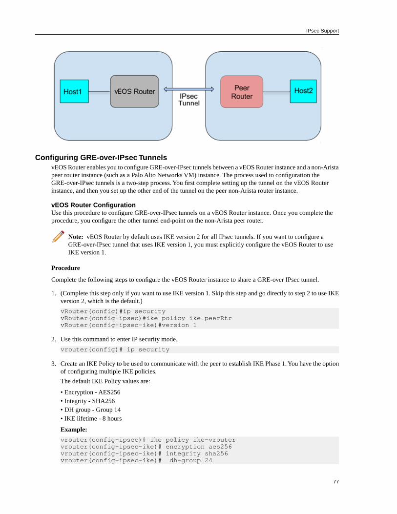
Configuring GRE-over-IPsec TunnelsvEOS Router enables you to configure GRE-over-IPsec tunnels between a vEOS Router instance and a non-Aristapeer router instance (such as a Palo Alto Networks VM) instance. The process used to configuration theGRE-over-IPsec tunnels is a two-step process. You first complete setting up the tunnel on the vEOS Routerinstance, and then you set up the other end of the tunnel on the peer non-Arista router instance.
vEOS Router ConfigurationUse this procedure to configure GRE-over-IPsec tunnels on a vEOS Router instance. Once you complete theprocedure, you configure the other tunnel end-point on the non-Arista peer router.
Note: vEOS Router by default uses IKE version 2 for all IPsec tunnels. If you want to configure aGRE-over-IPsec tunnel that uses IKE version 1, you must explicitly configure the vEOS Router to useIKE version 1.
Procedure
Complete the following steps to configure the vEOS Router instance to share a GRE-over IPsec tunnel.
1. (Complete this step only if you want to use IKE version 1. Skip this step and go directly to step 2 to use IKEversion 2, which is the default.)
vRouter(config)#ip securityvRouter(config-ipsec)#ike policy ike-peerRtrvRouter(config-ipsec-ike)#version 1
2. Use this command to enter IP security mode.
vrouter(config)# ip security
3. Create an IKE Policy to be used to communicate with the peer to establish IKE Phase 1. You have the optionof configuring multiple IKE policies.
The default IKE Policy values are:
• Encryption - AES256• Integrity - SHA256• DH group - Group 14• IKE lifetime - 8 hours
Example:
vrouter(config-ipsec)# ike policy ike-vrouter vrouter(config-ipsec-ike)# encryption aes256 vrouter(config-ipsec-ike)# integrity sha256 vrouter(config-ipsec-ike)# dh-group 24
77
IPsec Support

vrouter(config-ipsec-ike)# version 2 vrouter(config-ipsec-ike)# exitvrouter(config-ipsec)# ike policy ike-default vrouter(config-ipsec-ike)# version 2 vrouter(config-ipsec-ike)# exit
4. If the router is behind a NAT, configure the local-id with the local public IP address.Example:
vrouter(config-ipsec-ike)#local-id <public ip address>
5. Create an IPsec Security Association policy to be used in the data path for encryption and integrity. Youhave the option of enabling Perfect Forward Secrecy by configuring a DH group to the SA.Example: In this example, AES256 is used for encryption, SHA 256 is used for integrity, and Perfect ForwardSecrecy is enabled (the DH group is 14).
vrouter(config-ipsec)# sa policy sa-vrouter vrouter(config-ipsec-sa)# esp encryption aes256 vrouter(config-ipsec-sa)# esp integrity sha256 vrouter(config-ipsec-sa)# pfs dh-group 14 vrouter(config-ipsec-sa)# sa lifetime 2 vrouter(config-ipsec-sa)# exit
vrouter(config-ipsec)# sa policy sa-default vrouter(config-ipsec-sa)# exit
6. Bind (associate) the IKE and SA policies together using a IPsec profile. You must provide a shared-key,which should be common on both peers. (The default profile assigns default values for all parameters thatare not explicitly configured in the other profiles.)Example: In this example, tunnel mode is set to Transport. The IKE Policy ike-peerRtr and SA Policysa-peerRtr are applied to profile peer-Rtr. Dead Peer Detection is enabled and configured to delete theconnection when the peer is down for more than 50 seconds. The peer (peer-Rtr) is set to be the responder.
vrouter(config-ipsec)# profile defaultvrouter(config-ipsec-profile)# ike-policy ikedefaultvrouter(config-ipsec-profile)# sa-policy sadefaultvrouter(config-ipsec-profile)# shared-key aristavrouter(config-ipsec)# profile peer-Rtrvrouter(config-ipsec-profile)# ike-policy ike-peerRtrvrouter(config-ipsec-profile)# sa-policy sa-peerRtrvrouter(config-ipsec-profile)# dpd 10 50 clearvrouter(config-ipsec-profile)# connection addvrouter(config-ipsec-profile)# mode transport
7. Configure the WAN interface to be the underlying interface for the tunnel. You must specify an L3 addressfor the tunnel. If you do not, the vEOS Router cannot route packets using the tunnel.Example:
vrouter(config)# interface Et1 vrouter(config-if-Et1)# no switchportvrouter(config-if-Et1)# ip address 1.0.0.1/24 vrouter(config-if-Et1)# mtu 1500
8. Apply the IPsec profile to a new tunnel interface. You create the new tunnel interface as part of this step.Example: In this example, the new tunnel interface is Tunnel0. The new tunnel interface is configured touse IPsec, and the tunnel mode is set to GRE. The other end of the tunnel also needs to be configured as aGRE-over-IPsec tunnel.
vrouter(config)# interface tunnel0vrouter(config-if-Tu0)#ip address 1.0.3.1/24 vrouter(config-if-Tu0)#tunnel mode gre
78

vrouter(config-if-Tu0)#mtu 1400vrouter(config-if-Tu0)#tunnel source 1.0.0.1vrouter(config-if-Tu0)#tunnel destination 1.0.0.2 vrouter(config-if-Tu0)#tunnel ipsec profile vrouter
9. Create the GRE-over-IPsec tunnel interface in a VRF using the vrf forwarding command. Create theVRF (if needed), and then create the GRE tunnel interface and configure it. Make sure you specify the tunnelkey that is unique across all tunnels.
Note: If tunnels in different VRFs need to share the IPsec connection, specify the same source,destination, and ipsec profile.
Example:
vrouter(config)# vrf definition redvrouter(config-vrf-red)#rd 1:3 vrouter(config-vrf-red)# interface tunnel0 vrouter(config-if-Tu0)#ip address 1.0.3.1/24 vrouter(config-if-Tu0)#vrf forwarding red vrouter(config-if-Tu0)#tunnel mode gre vrouter(config-if-Tu0)#mtu 1400vrouter(config-if-Tu0)#tunnel source 1.0.0.1vrouter(config-if-Tu0)#tunnel destination 1.0.0.2vrouter(config-if-Tu0)#tunnel key 100 vrouter(config-if-Tu0)#tunnel ipsec profile vrouter
vrouter(config)# vrf definition blue vrouter(config-vrf-blue)#rd 1:4 vrouter(config-vrf-blue)# interface tunnel1 vrouter(config-if-Tu1)#ip address 1.0.4.1/24 vrouter(config-if-Tu1)#vrf forwarding blue vrouter(config-if-Tu1)#tunnel mode gre vrouter(config-if-Tu1)#mtu 1400vrouter(config-if-Tu1)#tunnel source 1.0.0.1vrouter(config-if-Tu1)#tunnel destination 1.0.0.2vrouter(config-if-Tu1)#tunnel key 200 vrouter(config-if-Tu1)#tunnel ipsec profile vrouter
You are now ready to configure the GRE-over-IPsec tunnel on the peer router.
Configuring VTI IPsec TunnelsvEOS Router enables you to configure VTI IPsec tunnels between a vEOS Router instance and a non-Aristapeer router instance (such as a Palo Alto Networks VM). You first complete setting up the tunnel on the vEOSRouter instance, and then you set up the other end of the tunnel on the non-Arista peer router instance.
vEOS Router ConfigurationUse this procedure to configure VTI IPsec tunnels on an Arista router instance. Once you complete the procedure,you configure the other tunnel end-point on the non-Arista peer router.
Note: vEOS Router by default uses IKE version 2 for all IPsec tunnels. If you want to configure a VTIIPsec tunnel that uses IKE version 1, you must explicitly configure the vEOS Router instance to use IKEversion 1.
Procedure
Complete the following steps to configure a vEOS Router instance to share a VTI IPsec tunnel.
79
IPsec Support

1. (Complete this step only if you want to use IKE version 1. Skip this step and go directly to step 2 to use IKEversion 2, which is the default.)
vRouter(config)#ip securityvRouter(config-ipsec)#ike policy ike-peerRtrvRouter(config-ipsec-ike)#version 1
2. Use this command to enter IP security mode.
vrouter(config)# ip security
3. Create an IKE Policy to be used to communicate with the peer to establish IKE Phase 1 options. You havethe option of configuring multiple IKE policies.
The default IKE Policy values are:
• Encryption - AES256• Integrity - SHA256• DH group - Group 14• IKE lifetime - 8 hours
Example:
vrouter(config)#ip securityvrouter(config-ipsec)#ike policy ike-vrouter-PAvrouter(config-ipsec)#integrity sha512 vrouter(config-ipsec)#encryption aes256vrouter(config-ipsec)#dh-group 20
4. If the router is behind a NAT, configure the local-id with the local public IP address.Example:
vrouter(config-ipsec-ike)#local-id <public ip address>
5. Create an IPsec Security Association policy to be used in the data path for encryption and integrity. Youhave the option of enabling Perfect Forward Secrecy by configuring a DH group to the SA.Example: In this example, AES256 is used for encryption, SHA 256 is used for integrity, and Perfect ForwardSecrecy is enabled (the DH group is 20).
vrouter(config-ipsec)#sa policy sa-vrouter-PAvrouter(config-ipsec)#esp encryption aes256vrouter(config-ipsec)#esp integrity sha256vrouter(config-ipsec)#sa lifetime 2vrouter(config-ipsec)#pfs dh-group 20
6. Bind (associate) the IKE and SA policies together using a IPsec profile. You must provide a shared-key,which should be common on both peers. (The default profile assigns default values for all parameters thatare not explicitly configured in the other profiles.)Example: In this example, the IKE Policy ike-vrouter-PA and SA Policy sa-vrouter-PA are applied to profilevrouter-PA. Dead Peer Detection is enabled and configured to delete the connection when the peer is downfor more than 30 seconds.
vrouter(config-ipsec)#profile vrouter-PAvrouter(config-ipsec-profile)#ike-policy ike-vrouter-PAvrouter(config-ipsec-profile)#sa-policy sa-vrouter-PAvrouter(config-ipsec-profile)#connection startvrouter(config-ipsec-profile)#shared-key Arista1234vrouter(config-ipsec-profile)#dpd 10 30 clear
7. Create a tunnel interface for the VTI tunnel. When tunnel mode is set to IPsec, you must configure a tunnelkey on the vEOS Router instance to ensure that traffic can be forwarded through the tunnel.
80

Example:
vrouter(config)#interface Tunnel1vrouter(config-if-Tu1)#mtu 1400vrouter(config-if-Tu1)#ip address 1.0.3.1/24vrouter(config-if-Tu1)#tunnel mode ipsecvrouter(config-if-Tu1)#tunnel source 10.2.201.149vrouter(config-if-Tu1)#tunnel destination 10.3.31.30vrouter(config-if-Tu1)#tunnel key 22vrouter(config-if-Tu1)#tunnel ipsec profile vrouter-PA
You are now ready to configure the VTI IPsec tunnel on the peer router (see Palo Alto VM Configuration onpage 81).
Palo Alto VM ConfigurationUse this configuration when pairing a Palo Alto VM instance and vEOS Router instance as tunnel end points ofan IPsec VTI IPsec tunnel.
Note: Please refer to the Palo Alto VM documentation for configuration details, including the differentinterfaces you can use to complete the configuration and all parameters and options.
Supported Tunnel Types
You can set up IPsec VTI tunnels when using the Palo Alto VM as a peer router instance with a vEOS Routerinstance. You cannot set up IPsec GRE-over-IPsec tunnels using this combination of router instances as peers.
Configuration Guidelines
There are some guidelines you should follow when configuring the Palo Alto VM. The guidelines are:
• IP address settings
Make sure you configure the first interface to be configured (typically named "eth0"), as the managementinterface. Use the public IP address on this interface to open the GUI of the Palo Alto VM.
• Management interface
This interface can be used only for control plane traffic. You cannot use it for data plane traffic.
• Management profile
When configuring the profile, select all of the protocols to be allowed on the management interface.
Procedure
1. Create a new management profile (select all of the protocols to be allowed on the management interface).
2. Create a new tunnel interface and specify the following parameters.
• Name: (for example, tunnel 1)• Virtual router: (Select the existing virtual router)• Security Zone: (Select the layer 3 internal zone, which is the zone from which the traffic originates.)• IP address: (Tunnel IP address)
3. Add a new IKE Crypto profile and specify the IKE Phase 1 options.
Note: Make sure the settings match the IKE Phase 1 settings on the other end of the tunnel (the vEOSRouter instance). This helps to ensure that the IKE Phase 1 negotiation to be successful.
• Name: (can be any name)• Virtual router: (Select the existing virtual router.)
81
IPsec Support

• Security Zone: (Select the layer 3 internal zone, which is the zone from which the traffic originates.)• IP address: (Tunnel IP address)
4. Configure the IKE Phase 1 gateway.
Note: Make sure the pre-shared key matches the key defined on the other end of the tunnel (the vEOSRouter instance).
5. Add a new IKE Crypto profile for the IKE Phase 2 options.
Note: Make sure the settings match the IKE Phase 2 settings on the other end of the tunnel (the vEOSRouter instance). This helps to ensure that the IKE Phase 2 negotiation of IPsec SAs is successful.
6. Create a new IPsec tunnel, and select the tunnel interface, IKE Phase 1 gateway, IKE Phase 1 crypto profile,and IKE Phase 2 crypto profile you defined earlier in the procedure. Selecting these elements binds them tothe new tunnel interface.
Note: Enter the destination IP address of the tunnel interface of the vEOS Router in the DestinationIP option (one of the Tunnel Monitor settings on the Palo Alto VM).
7. Create a new static route for the network that is behind the remote tunnel end point. This is needed to ensuretraffic is routed through the tunnel to the other tunnel end point.
8. Commit (save) the configuration.
Example of Running-configs for IPsec TunnelsThis example shows the running configurations for a VTI IPsec tunnel between a vEOS Router instance and aPalo Alto Networks VM router instance.
Running Config for vEOS1
ip security ike policy ikebranch1 integrity sha256 dh-group 15 !sa policy sabranch1 sa lifetime 2 pfs dh-group 14 !profile hq ike-policy ikebranch1 sa-policy sabranch1 connection add shared-key keyAristaHq dpd 10 50 clear !interface Ethernet1 no switchport ip address 1.0.0.1/24!interface Management1 ip address dhcp
82

!
interface Tunnel1 mtu 1404 ip address 1.0.3.1/24 tunnel mode ipsec tunnel key 100 tunnel source 1.0.0.1 tunnel destination 1.0.0.2 tunnel ipsec profile hq!
Running Config on Palo Alto VM
"ike": { "crypto-profiles": { "ike-crypto-profiles": [ { "@name": "veos12-IKE-Phase1", "hash": { "member": "sha512" }, "dh-group": { "member": "group20" }, "encryption": { "member": "aes-256-cbc" }, "lifetime": { "hours": "8" } } ]
"ipsec-crypto-profiles": [ { "@name": "veos12-IPSEC-Phase2", "esp": { "authentication": { "member": "sha256" }, "encryption": { "member": "aes-256-cbc" } }, "lifetime": { "hours": "2" }, "dh-group": "group20" }
"gateway": { "entry": { "@name": "veos12-IKE-Gateway", "authentication": { "pre-shared-key": { "key": "-AQ==ocHnGzxJ4JVLomPyHuZNlg84S7I=BCiu0HIvFeFOSQOx/gmhNQ==" } }, "protocol": {
83
IPsec Support

"ikev1": { "dpd": { "enable": "yes", "interval": "100", "retry": "100" }, "ike-crypto-profile": "veos12-IKE-Phase1" }, "ikev2": { "dpd": { "enable": "yes" }, "ike-crypto-profile": "veos12-IKE-Phase1" }, "version": "ikev2-preferred" }
"tunnel": { "ipsec": { "entry": { "@name": "veos12-IPSEC-Tunnel", "auto-key": { "ike-gateway": { "entry": { "@name": "veos12-IKE-Gateway" } }, "ipsec-crypto-profile": "veos12-IPSEC-Phase2" }, "tunnel-monitor": { "enable": "yes", "destination-ip": "1.0.3.1", "tunnel-monitor-profile": "Test" }, "tunnel-interface": "tunnel.1", "disabled": "no" } } } }
IPsec Show CommandsvEOS Router provides commands you can use to view all current (established) IPsec tunnels and to view allprofiles currently being used by established tunnels.
The show commands are:
• show ip security connections• show ip security connection detail• show ip security connections
Examples
This example shows the use of the show ip security connections command to view a summary ofall current (established) IPsec tunnels.
vrouter#show ip security connectionsTunnel Source Dest Status Uptime
84

Tunnel0 1.0.0.1 1.0.0.2 Established 14 minutes
Input Output Reauth Time589 bytes 608 bytes 8 hours 7 pkts 36 pkts
This example shows the use of the show ip security connection detail command to view thedetails for a particular IPsec tunnel.
vrouter#show ip security connection detailsource address 1.0.0.1, dest address 1.0.0.2 Inbound SPI 0x672F6CC3: request id 1, mode transport replay-window 32, seq 0x0 stats errors: replay-window 0, replay 0, integrity_failed 0 lifetime config: softlimit 18446744073709551615 bytes, hardlimit 18446744073709551615 bytes softlimit 18446744073709551615 pkts, hardlimit 18446744073709551615 pkts expire add 0 secs, hard 0 secs lifetime current: 589 bytes, 7 pkts add time Wed Aug 17 17:50:28 2016, use time Wed Aug 17 17:50:31 2016 Outbound SPI 0xc5f3c373: request id 1, mode transport replay-window 32, seq 0x0 stats errors: replay-window 0, replay 0, integrity_failed 0 lifetime config: softlimit 18446744073709551615 bytes, hardlimit 18446744073709551615 bytes softlimit 18446744073709551615 pkts, hardlimit 18446744073709551615 pkts expire add 0 secs, hard 0 secs lifetime current: 608 bytes, 7 pkts add time Wed Aug 17 17:50:28 2016, use time Wed Aug 17 17:50:31 2016
This example shows the use of the show ip sec applied-profile command to view all profiles currentlybeing used by established tunnels.
vrouter#show ip sec applied-profile Profile Name InterfaceArista Tunnel0
85
IPsec Support