VENTURI - M.K. Plastics · water to be directed to the wash ring at the top of the Venturi first,...
12
VENTURI PERCHLORIC ACID EXHAUST SYSTEM
Transcript of VENTURI - M.K. Plastics · water to be directed to the wash ring at the top of the Venturi first,...

VENTURIPERCHLORIC ACIDEXHAUST SYSTEM

VENTURI INTRODUCTION AND FEATURES
We are pleased to provide you with this Engineering brochure for the Plastifer® Venturi Exhaust Systems . The information contained within is also available on the M. K. Plastics Electronic Catalog (CD ROM) and at www.mkplastics.com. This CD includes information on all of the M. K. Plastics fans, exhaust systems and their components, and is available from your technical sales representative or M. K. Plastics directly. We look forward to assisting you with your important application. For over 40 years, M. K. Plastics has been engineering, designing, and fabricating thermoplastic and FRP ventilation components and systems for institutional and industrial applications. Founded in 1963, today M. K. Plastics has facilities and offices in Montréal, Québec, Canada; Spiez, Switzerland; Troy, OH and Mooers, NY, USA. In major cities throughout the United States and Canada, M.K. Plastics is represented by technical sales representatives. Other quality corrosion resistant fans are available from M.K. Plastics. Your local M.K. Plastics representative will be pleased to provide you with technical information upon request.
Axijet® High Plume Dilution Fan Axijet® LEADLAG™ Exhaust Fan Control System KVC High Plume Dilution Fan DHK Medium Pressure Centrifugal Fan DHK-NW High Pressure Centrifugal Fan CNW Centrifugal Fiberglass Fan PRVS High Pressure/Low Volume Centrifugal Blower RBK Roof Upblast & Sidewall Centrifugal Fiberglass Exhaust Fan AXT Axial Tubular Fan AXTC Centrifugal In-line Fan AXPR Axial Panel Fan FRP & PVC Control Dampers & Gravity Backdraft Dampers FRP & PVC Duct and Fittings
PERCHLORIC ACID EXHAUST SYSTEM
Plastifer®
What Is Perchloric Acid? HClO4 Perchloric acid is clear liquid that has no odor. Solutions below 73% at room temperature are strong non-oxidizing acids. Perchloric acid becomes a strong oxidizer when heated or at higher concentrations, at or above 73%. Organic, metallic and non-organic salts formed from oxidation are shock sensitive and pose a great fire and explosion hazard. There are many documented accidents resulting from perchloric acid. How are perchloric acid wastes handled? Perchlorate does not constitute any hazard in sanitary plumbing, nor is the concentration likely to build up in the surface waters. Much of the perchlorate may be degraded to chloride through the action of bacteria in sewage treatment systems. For specific information on perchloric acid waste handling, contact your local authority in regards to local codes and regulations.
M.K. Plastics Corp. Montréal, Québec www.mkplastics.com Page 2

VENTURI EXHAUST FAN DESIGN PERCHLORIC ACID EXHAUST SYSTEM
Plastifer®
EXHAUST FAN DESIGN Excerpt from CRC Handbook of Laboratory Safety. 4th Edition, 1995 by CRC Press LLC. 3.2.2.2.8. Perchloric Acid Hood. “As a minimum, the blades and any other portion of the exhaust fan which might come into contact with the perchloric fumes should be coated with PVC, Teflon, or another approved material which will resist the effects of the perchloric acid.” “An induction exhaust fan, where none of the fumes actually pass through any part of the motor or fan, is recommended...”
Fan destroyed by Perchloric acid Perchloric acid salts formed on ductwork
M.K. Plastics Corp. Montréal, Québec www.mkplastics.com Page 3

VENTURI DESIGN FEATURES
M.K. Plastics Corp. Montréal, Québec www.mkplastics.com Page 4
PERCHLORIC ACID EXHAUST SYSTEM
Plastifer®
MVT Plastifer® PERCHLORIC ACID EXHAUST SYSTEM A unique patent pending corrosion resistant FRP Perchloric Acid exhaust system specifically
designed by addressing the corrosion, fire, and explosion hazards of Perchloric Acid.
Integral washring, (Patented), efficientlywashes perchlorates fromsmooth interior
Air injector fan
Ø1/2" waterline pipe connectionfor internal duct spray nozzle
PVC manual control damper
All corrosion resistant FRP (fiberglassreinforced plastic) construction
To neutralizationwaste tank
Fume hood ducting
Ø1/2" waterline pipe connectionto the top washring + thermostatically
controlled heating cable
Curb cap for roof mounting
Ø1/2" waterline pipeconnected to the washroom
Laboratory fume hood
Flange connection
auxiliary washrings(every 10' to 12')
PVC flexible connector
Smooth internal ductworkwithout crevices, which cannot
collect volatile perchlorates
Insulation
MVT Plastifer® PERCHLORIC ACID EXHAUST SYSTEM DESIGN FEATURES Induced exhaust, no moving blower or moving parts in the air stream. Fiberglass Reinforced Plastic (FRP) construction providing superior corrosion resistance to
Perchloric acid. Vertical design preferable without horizontal runs. Internal wash down system to flush any accumulated crystals in the venturi. Fan is mounted outside the air stream for safe service and inspection. Stack is insulated to prevent condensation of acid vapors and formation of ice. Water wash line is electrically heat traced to prevent freezing in sub-zero applications. System is available with wash down timer and solenoid valves. System is designed to be self draining. Complies with "ACGIH“, NFPA 45 and "CRC Handbook on Laboratory Safety".
VENTURI GENERAL INFORMATION
M.K. Plastics Corp. Montréal, Québec www.mkplastics.com Page 5
PERCHLORIC ACID EXHAUST SYSTEM
Plastifer®
MVT Plastifer® PERCHLORIC ACID EXHAUST SYSTEM GENERAL INFORMATION Roof mounted or inside duct mounted. Curb or flange mounted. Additional FRP stack heights available. Additional spray nozzles and wash rings available for new or existing ductwork. Solenoid valves are available to control each wash ring or wash nozzle. A patent pending controller is available to sequence fan operation and wash cycles. MATERIALS OF CONSTRUCTION VENTURI: The venturi is manufactured in fiberglass reinforced plastic, corrosion resistant, without crevices where crystals may accumulate. It is flanged at both inlet and outlet and is engineered for connection with a pressure blower. AIR INJECTOR FAN: The belt driven pressure centrifugal fan is mounted in a convenient position alongside the venturi. A cut-off damper allows for adjustment of induced airflow. An inlet screen is provided as standard, plus an inlet weather cowl as an option. INSULATION: When installed on a roof, if necessary, the venturi, waterline and nozzle sections are fully insulated to prevent freezing, and the whole unit is clad in fiberglass. A strip heater, thermostatically controlled, is wrapped around the water line, and is provided in colder climates when the venturi is roof mounted.
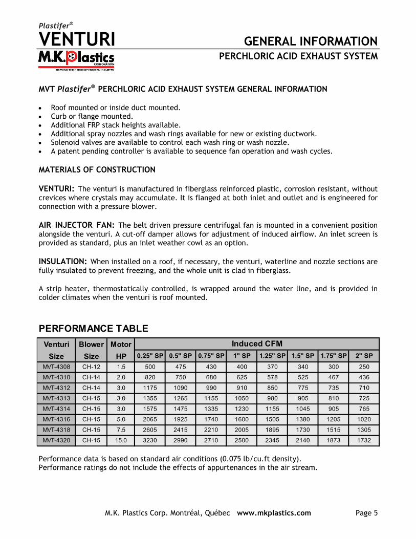
Performance data is based on standard air conditions (0.075 lb/cu.ft density). Performance ratings do not include the effects of appurtenances in the air stream.
PERFORMANCE TABLE
Venturi Blower Motor
Size Size HP 0.25" SP 0.5" SP 0.75" SP 1" SP 1.25" SP 1.5" SP 1.75" SP 2" SP
MVT-4308 CH-12 1.5 500 475 430 400 370 340 300 250
MVT-4310 CH-14 2.0 820 750 680 625 578 525 467 436
MVT-4312 CH-14 3.0 1175 1090 990 910 850 775 735 710
MVT-4313 CH-15 3.0 1355 1265 1155 1050 980 905 810 725
MVT-4314 CH-15 3.0 1575 1475 1335 1230 1155 1045 905 765
MVT-4316 CH-15 5.0 2065 1925 1740 1600 1505 1380 1205 1020
MVT-4318 CH-15 7.5 2605 2415 2210 2005 1895 1730 1515 1305
MVT-4320 CH-15 15.0 3230 2990 2710 2500 2345 2140 1873 1732
Induced CFM

VENTURI DIMENSIONS
M.K. Plastics Corp. Montréal, Québec www.mkplastics.com Page 6
PERCHLORIC ACID EXHAUST SYSTEM
Plastifer®
DIMENSIONS TABLE
VENTURI
SIZE
8 8 12 20.5 38.19 5.63 45 36.50 111 23.5 13.69 12 23 12 2 36
10 10 14 22.5 38.19 5.63 55 36.50 124 23.5 13.69 12 25 14 2 36
12 12 16 24.5 38.38 5.81 55 36.94 136 23.5 14.38 12 27 16 2 36
13 13 17 24.5 38.38 5.81 55 36.94 141 23.5 14.38 12 27 16 2 36
14 14 18 24.5 38.38 5.81 55 36.94 146 23.5 14.38 12 27 16 2 36
16 16 20 26.5 39.44 6.88 65 37.38 162 23.5 15.19 12 29 18 2 36
18 18 22 34 39.44 6.88 60 37.38 178 23.5 15.19 12 36.5 20 2 36
20 20 24 34 39.44 6.88 60 37.38 192 23.5 15.19 12 36.5 22 2 36
A B C D E F G H N P QJ K L M
We reserve the right to make changes to the dimensions. Rely on shop drawings only.
VENTURI DUCTWORK DESIGN
M.K. Plastics Corp. Montréal, Québec www.mkplastics.com Page 7
PERCHLORIC ACID EXHAUST SYSTEM
Plastifer®
DUCTWORK DESIGN EXCERPT FROM NFPA 45, STANDARD ON FIRE PROTECTION FOR LABORATORIES USING CHEMICALS… 6-11.4 “Ductwork for perchloric acid hoods and exhaust systems shall take the shortest and straightest path to the outside of the building and shall not be manifolded with other exhaust systems. Horizontal runs shall be as short as possible, with no sharp turns or bends. The ductwork shall provide a positive drainage slope back into the hood. Ductwork shall consist of sealed sections. Flexible connectors shall not be used”.
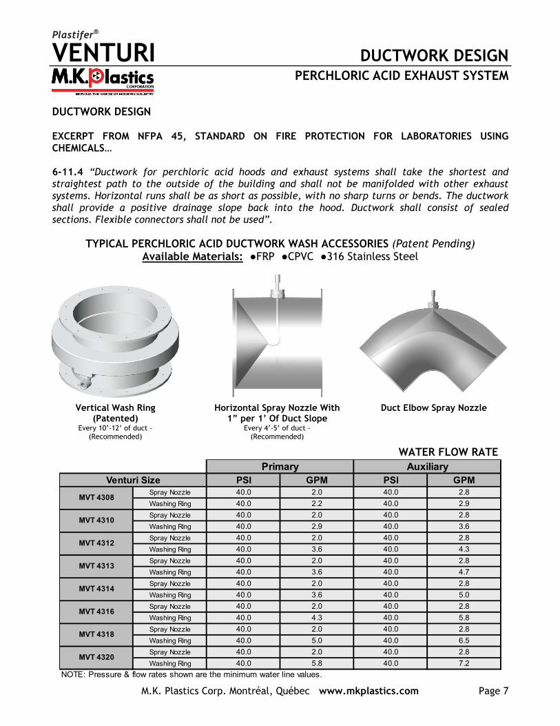
TYPICAL PERCHLORIC ACID DUCTWORK WASH ACCESSORIES (Patent Pending) Available Materials: ●FRP ●CPVC ●316 Stainless Steel
Vertical Wash Ring (Patented)
Every 10’-12’ of duct - (Recommended)
Horizontal Spray Nozzle With 1” per 1’ Of Duct Slope
Every 4’-5’ of duct - (Recommended)
Duct Elbow Spray Nozzle
WATER FLOW RATE
PSI GPM PSI GPMSpray Nozzle 40.0 2.0 40.0 2.8
Washing Ring 40.0 2.2 40.0 2.9
Spray Nozzle 40.0 2.0 40.0 2.8
Washing Ring 40.0 2.9 40.0 3.6
Spray Nozzle 40.0 2.0 40.0 2.8
Washing Ring 40.0 3.6 40.0 4.3
Spray Nozzle 40.0 2.0 40.0 2.8
Washing Ring 40.0 3.6 40.0 4.7
Spray Nozzle 40.0 2.0 40.0 2.8
Washing Ring 40.0 3.6 40.0 5.0
Spray Nozzle 40.0 2.0 40.0 2.8
Washing Ring 40.0 4.3 40.0 5.8
Spray Nozzle 40.0 2.0 40.0 2.8
Washing Ring 40.0 5.0 40.0 6.5
Spray Nozzle 40.0 2.0 40.0 2.8
Washing Ring 40.0 5.8 40.0 7.2
NOTE: Pressure & flow rates shown are the minimum water line values.
MVT 4314
MVT 4316
MVT 4318
MVT 4320
MVT 4308
MVT 4310
MVT 4312
MVT 4313
Primary AuxiliaryVenturi Size

VENTURI WASHDOWN CONTROLLER
M.K. Plastics Corp. Montréal, Québec www.mkplastics.com Page 8
PERCHLORIC ACID EXHAUST SYSTEM
Plastifer®
Purpose... Laboratory experiments involving perchloric acid digestions create vapors that condense and crystallize in the exhaust system. These crystals (perchlorates) are volatile and can cause Fires or Explosions, unless washed from the exhaust system. The MVT Plastifer Perchloric Acid Wash Controller used in conjunction with the MVT Plastifer Perchloric Acid Exhaust system, safely and automatically washes perchlorates from the perchloric acid vapor exhaust system.
How it works... Through the use of a PLC, wash water is directed via solenoid valves to each wash point in the Venturi system. When the researcher shuts off the MVT Venturi exhaust fan, the wash system is energized, sequencing wash water to be directed to the wash ring at the top of the Venturi first, the inlet Venturi wash nozzle second, and then the auxiliary duct mounted wash rings. This wash cycle continues in descending order (from the top of the stack to the fume hood). Wash duration per wash nozzle is fully programmable. Washdown can be both manual or automatic. MVT Plastifer® Perchloric Acid Exhaust System Washdown Controller Specification 1. The MVT Plastifer Perchloric Acid Venturi Washdown Controller shall be provided by M.K. Plastics
Corporation. 2. Control unit shall be enclosed in a NEMA 3R enclosure that shall be remote mounted in the laboratory. The
control panel shall house the PLC, switches and wiring terminals. The panel shall consist of washdown/exhaust fan control switches, indicator lights, manual/automatic toggle switch (mounted on the enclosure door), and PLC display per fan, (mounted inside the enclosure). Power input shall be 110 VAC.
3. The wash system shall include three way water solenoid valves and wiring terminals, provided by the fan manufacturer.
4. Interconnecting wiring between the controller and solenoid valves, the water piping between the solenoid valves and the wash rings shall be the responsibility of the installing contractor.
5. A facility safety manager shall determine the wash cycle duration and the wash duration of each nozzle, and ensure the correct programming of the wash cycle. Washdown cycle shall be either a manual or automatic operation.
6. The exhaust fan shall be turned on by the fume hood operator, by pressing the RUN FAN button on the control panel.
7. Washdown cycle shall be either a manual or automatic operation. 8. The MVT exhaust system fan shall be turned off by the fume hood operator by pressing the STOP FAN button
on the control panel. This shall initiate a washdown cycle; upon completion the fan will remain turned off. 9. The washdown cycle shall be energized by the fume hood operator by pressing the RUN WASH button on the
control panel. The exhaust fan shall automatically turn off during the cycle; upon completion the fan will automatically turn back on.
10. Upon washdown startup the respective solenoid valves shall be energized, starting the wash cycle sequentially at the highest wash ring (top of the stack), down through all the wash rings and nozzles in the perchloric exhaust system to the hood.
11. Refer to MK Plastics submittal programming guide for specific programming information. A detailed ‘Training Guide’ booklet will be included with each timer; this gives information on wiring, installation and programming.

VENTURI WASHDOWN CONTROLLER
M.K. Plastics Corp. Montréal, Québec www.mkplastics.com Page 9
PERCHLORIC ACID EXHAUST SYSTEM
Plastifer®
MVT Plastifer® PERCHLORIC ACID EXHAUST SYSTEM THE 3-WAY SOLENOID VALVES
As part of the Plastifer® Venturi wash down control package, M.K. Plastics will provide water solenoid valves and wiring terminals. The 3-way valve enables drainage of the water line after wash down completion, to prevent freezing in outdoor applications in colder climates. These valves are diaphragm operated, solenoid pilot controlled.
OPTIONAL POWER SURGE & POWER FAILURE PROTECTION M.K. Plastics can offer an optional washdown controller battery back-up, (UPS), which will protect against possible power surges and provide full timer operation, including washdown, during a power failure, (operational time will depend on load).
VENTURI SPECIFICATIONS
M.K. Plastics Corp. Montréal, Québec www.mkplastics.com Page 10
PERCHLORIC ACID EXHAUST SYSTEM
Plastifer®
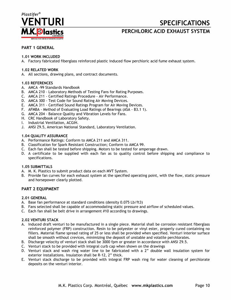
PART 1 GENERAL 1.01 WORK INCLUDED A. Factory fabricated fiberglass reinforced plastic induced flow perchloric acid fume exhaust system. 1.02 RELATED WORK A. All sections, drawing plans, and contract documents. 1.03 REFERENCES A. AMCA -99 Standards Handbook B. AMCA 210 - Laboratory Methods of Testing Fans for Rating Purposes. C. AMCA 211 - Certified Ratings Procedure - Air Performance. D. AMCA 300 - Test Code for Sound Rating Air Moving Devices. E. AMCA 311 - Certified Sound Ratings Program for Air Moving Devices. F. AFMBA - Method of Evaluating Load Ratings of Bearings (ASA - B3.1 1). G. AMCA 204 - Balance Quality and Vibration Levels for Fans. H. CRC Handbook of Laboratory Safety. I. Industrial Ventilation, ACGIH. J. ANSI Z9.5, American National Standard, Laboratory Ventilation. 1.04 QUALITY ASSURANCE A. Performance Ratings: Conform to AMCA 211 and AMCA 311. B. Classification for Spark Resistant Construction; Conform to AMCA 99. C. Each fan shall be tested before shipping. Motors to be tested for amperage drawn. D. A certificate to be supplied with each fan as to quality control before shipping and compliance to
specifications. 1.05 SUBMITTALS A. M. K. Plastics to submit product data on each MVT System. B. Provide fan curves for each exhaust system at the specified operating point, with the flow, static pressure
and horsepower clearly plotted. PART 2 EQUIPMENT 2.01 GENERAL A. Base fan performance at standard conditions (density 0.075 Lb/ft3) B. Fans selected shall be capable of accommodating static pressure and airflow of scheduled values. C. Each fan shall be belt drive in arrangement #10 according to drawings. 2.02 VENTURI STACK A. Induced draft venturi to be manufactured in a single piece. Material shall be corrosion resistant fiberglass
reinforced polymer (FRP) construction. Resin to be polyester or vinyl ester, properly cured containing no fillers. Material flame spread rating of 25 or less shall be provided when specified. Venturi interior surface shall be smooth without crevices, minimizing the deposit of unstable and volatile perchlorates.
B. Discharge velocity of venturi stack shall be 3000 fpm or greater in accordance with ANSI Z9.5. C. Venturi stack to be provided with integral curb cap when shown on the drawings D. Venturi stack and wash ring water line to be fabricated with a 2” double wall insulation system for
exterior installations. Insulation shall be R-12, 2” thick. E. Venturi stack discharge to be provided with integral FRP wash ring for water cleaning of perchlorate
deposits on the venturi interior.

VENTURI SPECIFICATIONS
M.K. Plastics Corp. Montréal, Québec www.mkplastics.com Page 11
PERCHLORIC ACID EXHAUST SYSTEM
Plastifer®
2.03 FAN HOUSING A. Fan housing to be aerodynamically designed with high-efficiency inlet, engineered to reduce incoming air
turbulence. B. Fan housing shall be manufactured in specifically formulated resins and reinforced with fiberglass for
structural strength, or heavy duty epoxy coated cast aluminum. C. Fan outlet to be flanged. Fan inlet to be provided with either a PVC mesh screen, or spiral wire type with
an electrostatic zinc finish. D. A manual control damper fabricated of UV inhibited PVC shall be provided on the fan discharge for flow
control. E. A flexible connector fabricated of UV inhibited flexible PVC shall connect the induction blower discharge
and the venturi stack using 304 stainless steel clamps. F. Standard finish color to be light gray. 2.04 FAN IMPELLER A. Impellers shall either be of flat radial blade design in solid molded FRP or epoxy coated cast aluminum
construction. The impeller shall be electronically balanced both statically and dynamically Grade GS.3 per AMCA 204-96 Standard.
2.05 FAN BASE SUPPORT A. Arr. #10 or #9 support to be manufactured in formed steel and to be baked polyester coated. B. An access panel to be standard to provide accessibility to the motor junction box. C. An OSHA belt guard shall be provided to cover the sheaves and belts. 2.06 FAN MOTORS AND DRIVES A. Motors to be TEFC and premium-efficiency with a 1.15 service factor. B. Belts and pulleys are to be accessible for service and maintenance. C. Shafts to be AISI -1045 carbon steel. The shaft shall not be in the corrosive air stream. D. Bearings shall be regreaseable spherical pillow block and have a minimum L-10 life of 200,000 hours life. E. Drive guard to be supplied and manufactured according to OSHA standards. F. Fans up to 5 HP motor to have variable pitch. 2.07 WASH SYSTEM CONTROLS A. When specified, the manufacturer shall provide a NEMA 3R control panel complete with washdown/
exhaust fan control switches, indicator lights, manual/automatic toggle switch (mounted on the enclosure door), and PLC display per fan, (mounted inside the enclosure), control circuitry, interface terminal strip and three way water solenoid valves (shipped loose).
B. Venturi exhaust system shall be de-energized during wash cycle. C. Wash cycle time shall be determined by the Facility Safety Manager. D. Washdown shall be either manually operated or automatically set. E. Optional battery back-up, (UPS), which will protect against possible power surges and provide full timer
operation during a power failure, when specified. 2.08 AUXILIARY WASH RINGS A. Venturi exhaust system manufacturer shall provide (when specified) auxiliary FRP wash rings to be
installed every 10 to 12 feet of vertical duct work, spray nozzles to be in horizontal duct at every 4 to 5 feet, and duct elbow spray nozzles.
B. Wash ring sizes to be provided as scheduled. 2.09 ACCEPTABLE MANUFACTURERS A. M.K. Plastics Corporation, Model MVT.
50-01-FEBRUARY 2009
CONDITIONS OF SALE
1. Prices quoted are current; prices prevailing at time of shipment will apply. Material in stock is offered subject to prior sale. All Sales Contracts arising out of this quotation shall be subject to our regular conditions shown on this side.
2. All deliveries quoted are based on availability of material and labor at the time of quotation and subject to changes. Deliveries are contingent upon strikes, accidents, fires and other causes and we shall not be liable for any loss or damage caused by delays beyond the control of the company.
3. Goods invoiced up to and including the last day of the calendar month, shall be paid for not later than the last business day of the following month. The Company reserves the right to charge interest at commercial rates on any overdue account.
4. Any order accepted by us cannot be countermanded, revised or cancelled without our written consent and upon such terms as will indemnify us against any loss. The word “loss” as used herein shall include, but not be limited to, cost of materials, special machinery, tools, jigs and fixtures built or purchased for the contract and all parts in process, fabricated in whole or in part by previous customer authorization.
5. No contract arising from the acceptance of this quotation shall be valid and binding until approved by the company, such contract shall be governed by and interpreted in accordance with the laws of the Province of Québec.
6. All memoranda, drawings and information furnished by the company shall remain its property and shall be considered business or trade secrets received in trust and confidence for the sole purpose of assisting the buyer.
7. Orders to customer’s drawings or descriptions are filled with the understanding that the customer assumes the obligation to protect M.K. Plastics Corporation from any action for infringements of patents.
8. No modification of the above conditions of Sale shall be effected by our receipt or acknowledgement of a purchase order containing additional or different conditions.
LIMITATION OF WARRANTY AND LIABILITY
We will not be responsible for the damage to equipment or materials through improper
installation, storage, improper servicing, or through attempts to operate it in excess of its
rated capacity or recommended use, intentional or otherwise. We will not be responsible for
consequential damage.
Based on the fact that M.K. Plastics Corp. has no direct control over the actual handling and use of its products
in the field, M.K. Plastics Corp. does not assume any liability for any loss of custumer or any personnel or any physical
damages claimed by anyone due to a failure or cause attributed to the use of its products. In no event shall M.K. Plastics Corp.
be responsible for consequential damages of any such defective material or workmanship, including but not limited to the buyer’s
loss of material or profit, increased expense of operation, downtime or reconstruction of the work and in no event shall M.K. Plastics Corp.
obligation under this warranty exceed the original contract price of the defective item.
M.K. Plastics Corp. warrants its equipment, products and parts, to be free from defects in workmanship and material under normal use and service
for one (1) year after delivery to the first user. Our obligation under this warranty being limited to repairing or replacing, at our option, without
cost at our factory any part, or parts which shall , within such warranty period, be returned to us with transportation charges prepaid, and which our
examination shall disclose to our satisfaction to have been defective.
M.K. Plastics Corp. will not be responsible for the cost of removal of a defective product or parts or the installation of a replaced product or parts, or for costs
due for its removal, crating or shipping.
On account of variables including but not limited to, vibration, system noise characteristics, motor overloading or change in voltage conditions, the specifics of
customer application of equipment or other system conditions, M.K. Plastics Corp. does not expressly warrant its equipment for any specific purpose.
The customer and its agents are responsible for the selection and application of M.K. Plastics Corp. products, including their fitness for the purpose and performance
intended. Consequently, the customer on behalf of its agents assumes all liability related to the user/misuse, application and selection of the M.K. Plastics Corp.
4955 De Courtrai Ave., Montreal, Quebec H3W 1A6Trimex Building, Route 11, Mooers, NY 12958
Spiez, Switzerland tel: (514) 871-9999 / (888) 278-9988 fax: (514) 871-1753
www.mkplastics.com