Ventra XDR 450D Software Manual - ventrainc.com
32
Ventra XDR-450/D Mobile DVR Software Manual 5CH Hybrid Mobile DVR Ventra Technology Inc www.ventrainc.com [email protected] This manual is only for the XDR software. For Hardware manual, please refer to XDR User Guide
Transcript of Ventra XDR 450D Software Manual - ventrainc.com

Ventra XDR-450/D Mobile DVR Software Manual
5CH Hybrid Mobile DVR
Ventra Technology Inc
www.ventrainc.com
This manual is only for the XDR
software. For Hardware manual,
please refer to XDR User Guide


Contents
1. Software Overview ........................................................................................................... 5
2. Installation Software ........................................................................................................ 5
2.1. Software Installation ............................................................................................ 5
3. Ventra XDR Program Log In ............................................................................................ 6
3.1. Log In .................................................................................................................. 6
3.1.1. Software Log In ........................................................................................... 6
3.1.2. Advance (Server Management) .................................................................. 7
3.1.2.1. Add Server ........................................................................................ 7
3.1.2.2. Delete Server .................................................................................... 7
3.1.2.3. Edit Sever ......................................................................................... 7
3.2. Software Dashboard ........................................................................................... 8
3.3. Video Playback - Selecting date / Event ............................................................. 9
3.3.1. Playback Local SD card / HDD ................................................................. 10
3.3.1.1. Select Channel................................................................................ 11
3.3.1.2. Playback Server .............................................................................. 12
3.3.1.3. Playback Controls ........................................................................... 13
3.3.1.4. Playback Controls - CH display, Speed, Progress ......................... 14
3.3.2. Playback Speed ........................................................................................ 15
3.3.2.2. Playback - Audio, Enlarge, Image Snapshot ................................. 16
3.3.2.2. Playback - Full Screen, Display Layout ......................................... 17
3.3.2.3. Playback - CH Window Selection, Close Window ......................... 18
3.3.2.4. Playback - Mosaic / Privacy setting ............................................... 19
3.3.3. Video/Map Mode / Route History .............................................................. 20
3.3.3.1 View - Map Only Mode / Video Only Mode .................................... 21
3.3.3.2. View - Map Only / Frame Information ............................................ 22
3.4. Save / Export Video, Channels ........................................................................ 23
3.4.1.1. Export Video - Standard, EXE format ............................................. 23
3.4.1.2. Export Video - AVI format ............................................................... 24
3.4.1.3. Download Files to Local HD ........................................................... 25
3.4.1.4. Download Files to Server ............................................................... 26
3.4.2. Search / Add Events ................................................................................. 27
3.4.2.1. Search Criteria ................................................................................ 27
3.4.2.2. Add Events – Speed, Alarm ........................................................... 27
3.4.2.3. Event Verify, Delete ........................................................................ 28
3.5. System Setup – Add / Edit User Role, Language, Speed / Temp Unit ............ 29
3.5.1.1. User Permission / Add User ........................................................... 29
3.5.1.2. Map, Language ............................................................................... 30
3.5.1.3. Speed, Temperature Unit ............................................................... 31
Technical Specification ............................................................................. 32
Warranty / RMA ........................................................................................ 33

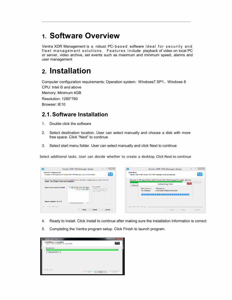
1. Software Overview
Ventra XDR Management is a f l e e t m a nag em en t s o lu t i o ns . or server, video archive, set events such as maximum and minimum speed, alarms and user management
2. Installation
Computer configuration requirements:
CPU: Intel i5 and above
Memory: Minimum 4GB
Resolution: 1280*760
Browser: IE10
2.1. Software Installation
1. Double click the software
2. Select destination location.free space. Click “Next” to
3. Select start menu folder. User can select manually and click Next to
Select additional tasks. User can
4. Ready to install. Click Install to continue after making sure the installation
5. Completing the Ventra program setup. Click Finish to launch program.
Overview
a robust PC- b as e d software i de a l f o r s ec u r i t y a n d f l ee t m an agem e n t s o l u t i ons . F e a tu r e s i nclude: playback of video on local PC
set events such as maximum and minimum speed, alarms and
Installation
Computer configuration requirements: Operation system: Windows7 SP1、Windows 8
Installation
location. User can select manually and choose a disk free space. Click “Next” to continue
menu folder. User can select manually and click Next to continue
can decide whether to create a desktop. Click Next to continue
Ready to install. Click Install to continue after making sure the installation information
Completing the Ventra program setup. Click Finish to launch program.
i de a l f o r s ec u r i t y a n d video on local PC
set events such as maximum and minimum speed, alarms and
Windows 8
with more
continue
to continue
information is correct

3. Ventra XDR Software
This section covers how to login to the Ventra so
PC or sever. Insert SD Card from XDR to view data.
NOTICE:
SD card MUST be formatted in the XDR prior to any recording. XDR utilizes a proprietary file encryption and cannot be Guide on how to format
3.1. Log In
3.1.1. Log In to Ventra XDR Software
1. Double click Ventra software
2. Choose connection Type
(Choose Local - Typical
3. Enter User and Password
User ID = admin (can change that in User Profile / Add User)
PW = there are no password
/ Add User
4. If Connecting to Server, e
the same time) or choose
Notice: The default port of server is 7264
changed in the server.
5. Click “OK” to enter program
6. If enter wrong IP, User ID
7. User can select the previous
8. User can click Save passwor
XDR Software Log In
This section covers how to login to the Ventra software to playback recordings on a local
SD Card from XDR to view data.
SD card MUST be formatted in the XDR prior to any recording. XDR utilizes a proprietary file encryption and cannot be recognized in Windows OS. Please refer to XDR User
to Ventra XDR Software
software desktop icon
- Local or Server
Typical setup are on local PC)
Enter User and Password
(can change that in User Profile / Add User)
password for the first initial login, can change that in User Profile
If Connecting to Server, enter the IP address of server. (Supports domain name at
choose the previous server name.
Notice: The default port of server is 7264. IP needs to add a new port if the default one
program
or password, Login fail will display
previous IP or user that logged in successfully
password and keep user & password for future login
ftware to playback recordings on a local
SD card MUST be formatted in the XDR prior to any recording. XDR utilizes a proprietary in Windows OS. Please refer to XDR User
, can change that in User Profile
nter the IP address of server. (Supports domain name at
. IP needs to add a new port if the default one is
n

3.1.2. Advance (Server
When log in, user can click “Advance” to
3.1.2.1. Add Server
Click “Advance” and “Add” to input server name and
Supports up to 22 letters respectively in the server name and
domain name
Notice: The default port of server is 7264. IP needs to add a new port if the default is
the server
Return to Log in interface, click the button
3.1.2.2. Delete Server
Click “Advance”, then click “Delete” to delete the
3.1.2.3. Edit Sever
Click “Advance”, then click “Edit” to input server name and
Advance (Server Management)
When log in, user can click “Advance” to set advanced settings
Click “Advance” and “Add” to input server name and IP
22 letters respectively in the server name and IP. IP address supports
Notice: The default port of server is 7264. IP needs to add a new port if the default is changed in
in interface, click the button to automatically select the added server
Server
Click “Advance”, then click “Delete” to delete the server
Click “Advance”, then click “Edit” to input server name and IP
address supports
changed in
server

3.2. Software dashboard
The software dashboard displays playback mode, vehicle list, download options, as well as options, settings and map. Data can be viewed, and accessed either from a local computer or server, where the information is stored. *Local computer access is most common
1. Live: Applicable ONLY for XDR models with cellular connection for remote viewing. Not available on
the XDR-400 model
2. Playback: Playback of recordings from SD cards / HDD, or data previously stored on server
3. Download: Download and save individual files/recordings
4. Setting: System setting / configuration
5. View Mode: Displays viewing in Map, Video, Video and Map
6. Search: Search for vehicles
7. Refresh: Refresh vehicle or storage list
8. List: Displays vehicle list in Live Mode (XDR models with 3G viewing), or displays list of SD card / HDD
in playback mode
9. Add / Delete: Add / Delete vehicle groups
10. Server configuration: Manage / Set IP address and Ports

10
3.3. Playback – Selecting Date / Event
1. Choose a vehicle or SD card from HDD Tab
2. Choose date and Event - if applicable
3. Double click “Search” to display calendar
4. In calendar, GREEN indicates normal recording; RED indicates alarm
recording; Red dot indicates black box data
5. Select desired day
(XDR supports various Event Customization – Over / Low Speed, Alarm, Temperature)
Events parameters can be programmed in Section 3.4.2.1 – Search / Advance Setting

11
3.3.1 Playback Local SD / HDD 3.3.1.1 Select channel
1. After selecting search criteria, double click the date in the calendar. If there is video
data, it will go to the channel choice page (as shown in pic 1 and pic 2), choose the
channel to playback (default is all channels with data); If only with black box data,
then go directly into the map page.
2. Click Play button and go into the video playback page
(Picture 1, Video and Map - with GPS signal for black box metadata)
(Picture 2, Video only data)

12
3.3.1.2 Playback - From Server
Playback via server requires files to be previously saved on a server for archiving purpose.
Vehicle list only shows vehicle groups within management and devices under the groups.
The number after title shows the total number of vehicles

13
3.3.2 Playback Controls
1. Select the desired vehicle from the list
2. Play / Pause
Click to play, press to pause, click , to resume playback
Click to stop playback.
1. Select the opened channel, Click to turn of sound, and it turns to
2. After activation of sound, click to turn on sound
3. Main stream has better sound quality than sub stream

14
3.3.2.1 Playback Controls - Continue
1. Channel display
Only shows channels with data
Blue indicates normal video, orange indicate alarm video
2. Zoom in, Zoom out, time graph
Click or upper scroll mouse, can zoom in time bar (maximum 24 hours)
Click or down scroll mouse, to zoom out time bar (maximum 1 minute)
3. Play progress
Green vertical line shows playing progress, left click on the mouse to the desired playback
time
4. Right Click – Mouse
Press right key of mouse, and drag mouse - left/right to move the progress of playback

15
3.3.2.2 Playback Speed
Without GPS receiver black box data, the speed curve shows blank.
1. Zoom in, zoom out channel bar
Click or upper scroll mouse, can enlarge speed’s time bar (maximum is 24 hours).
Click Or down scroll to zoom out speed’s time bar (maximum 1 minute).
2. Maximum value and minimum value
When playback, user can see GPS speed and pulse’s maximum value and
minimum value
Slow Playback
Click to slow playback, click one time to slow one time, maximum
support 1/32 speed playback. This function does not support if recording only
conta ins black box data
Fast Playback
Click to fast play during playback, click one time to fast double, maximum
support x32 speed playback. This function does not support if recording only
conta ins black box data
Last Frame
Click to shows the last frame image, and pause playback, this function do not
supported if only with black box data.

Next Frame
Click during playback,
data.
Sound
Click during playback,
volume of. This function does
Digital Enlarge
Click , and then drag the mouse left
double click enlarge area, will resume to normal
Snapshot – Image
1. Choose the displayed video channel,
snapshot window will prompt up
2. The prompt message will disappear in 6
3. Click the content from the prompt up, the picture will
16
playback, this function cannot supported if only with
playback, ,drag bar to adjust the
does not support if recording only conta ins black box
, and then drag the mouse left key, select the district need to be enlarge,
click enlarge area, will resume to normal playback
Choose the displayed video channel, click on the bottom right corner. The
window will prompt up
The prompt message will disappear in 6 seconds
Click the content from the prompt up, the picture will open
with black box
to adjust the
black box data
to be enlarge,
bottom right corner. The
17
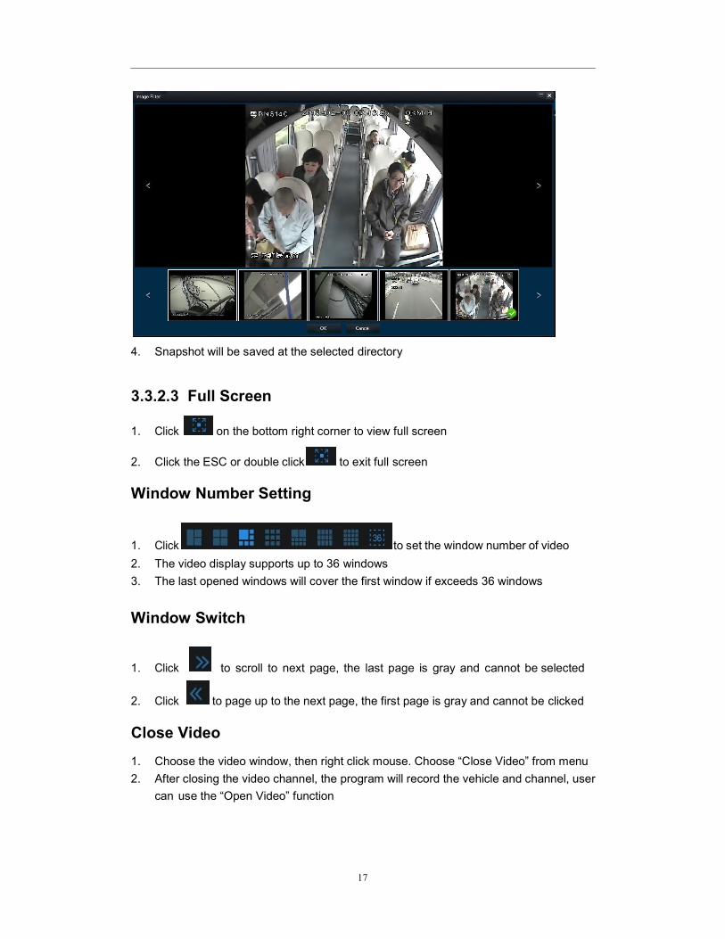
4. Snapshot will be saved at the selected directory
3.3.2.3 Full Screen
1. Click on the bottom right corner to view full screen
2. Click the ESC or double click to exit full screen
Window Number Setting
1. Click to set the window number of video
2. The video display supports up to 36 windows
3. The last opened windows will cover the first window if exceeds 36 windows
Window Switch
1. Click to scroll to next page, the last page is gray and cannot be selected
2. Click to page up to the next page, the first page is gray and cannot be clicked
Close Video
1. Choose the video window, then right click mouse. Choose “Close Video” from menu
2. After closing the video channel, the program will record the vehicle and channel, user
can use the “Open Video” function
18
Close All Video
Choose any window, right click the mouse. Choose “Close All” on the prompt up menu to
close all videos
Open Video
Choose desired video channel, then right click the mouse, choose “Open Video” on the
prompt menu
Open All Video
Choose any window, then right click the mouse, choose “Open All” on the prompt menu
Clear Video
1. Choose opened video window or closed window, then right click on mouse, choose
clean history” on the prompt menu
2. After clean up of video, program will no longer record vehicle and channel number,
so the “open video” function can’t be used
Full Screen
Click to full screen, press “ESC” key to exit full screen. Press “blank” key to
pause/play video
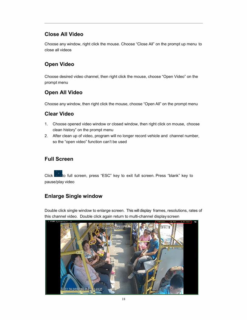
Enlarge Single window
Double click single window to enlarge screen. This will display frames, resolutions, rates of
this channel video. Double click again return to multi-channel display screen

19
3.3.2.4 Mosaic Setting
Click , on the upper right of window to pop up dialog for mosaic se tup . Drag
mouse to setup area and confirm. Every channel supports maximum 20 points of mosaic
After setting
Click won’t save the mosaic setup. Real time setup can be done during playback.
To cancel the mosaic, click on the upper right hand corner and click “Clear”
button. This will then cancel the settings for mosaic

20
3.3.3 Video/ Map - Route History
In this mode, the program displays both video and map simultaneously
View Vehicle Route History
1. Lock the vehicle:
Click on the upper right and can cancel the vehicle locked, and the icon will change
to Click again to lock the vehicle, In playback, in the map will move with the
map.
2. Route display and hide:
Select the icon on the right side of the map, click on the icon to hide the vehicle
route, and the icon will change to ; Click again to display the route
3. Alarm group:
Vehicle route, If there is only one alarm in a dot, Shown as ; If multiple alarms are in a
dot, shown as . The number it indicates the alarm No..
21
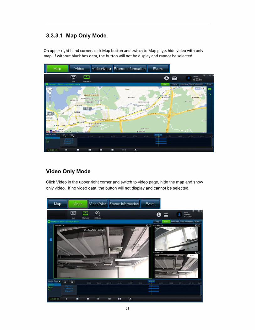
3.3.3.1 Map Only Mode
On upper right hand corner, click Map button and switch to Map page, hide video with only
map. If without black box data, the button will not be display and cannot be selected
Video Only Mode
Click Video in the upper right corner and switch to video page, hide the map and show
only video. If no video data, the button will not display and cannot be selected.

22
3.3.3.2 Video/Map Mode
Click Video/Map button in the upper right hand corner to switch to Video/Map page view.
If there is no video or black box data, the button is unavailable d and cannot be selected.
Frame Information
Click frame Information on the upper right hand corner to display Black Box metadata

23
3.4.1 Export / Save Video
Standard Clip (Default Type)
Download H.264 file in the server to specified path of current PC
1. In the clip setting page, adjust start and end time again
2. Choose channel. All data channel have been chosen by default
3. Select Standard
4. Revise local save path.
5. Click “OK”, number in the download icon will become “+1”
6. Following download status please refer to local download in download center.
Export EXE File
1. Transfer H.264 file in the server to EXE format file,then download to specified path in local PC
2. In the clip setting page,adjust start and end time again
3. Choose channel. All data channels have been chosen by default
4. Select Standard .
5. Revise local save path
6. Click “OK”, the number in the download icon will become +1 .
Following download status please refer to local download in download center.

24
3.4.1.2 AVI Export AVI
1. Transfer H.264 file in the server to AVI format file, then download to specified path in
local PC
2. In the clip setting page, adjust start and end time again
3. Choose channel. All data channel have been chosen by default
4. Select AVI .
5. Revise local save path
6. Click “OK”, the number in the download icon will become +1 .
Following download status please refer to local download in download center
Editing
Click during playback, then playback will pause, “curve control”
and “playback bar” will look like this(see picture below).
The green dotted line on the left is the video clip start time, and green solid line is the
middle of playback time, while green dotted line on the right is the end of the video clip to
be exported.
To adjust the time, simply drag the dotted lines on each side to desired time.

25
3.4.1.3 Download Center
Save to Local
Only one record can be downloaded at a time

26
3.4.1.4 Save to Server
3.4.2 Search / Add Event
3.4.1.1. Search Parameter
Date: One day, recent 3 days, recent 5 days, recent one week, recent 2 weeks, recent
one month, all, user-defined
Speed: >, >=, <, <=, between, except
GEO Fence: (Not Available for XDR-400)
Event: Emergency, high speed, low speed, IO1, IO2, IO3, IO4, IO5, IO6, IO7, IO8.
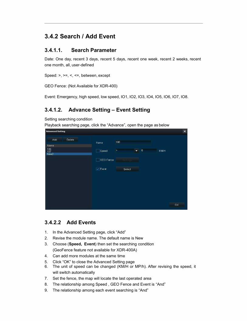
3.4.1.2. Advance Setting – Event Setting
Setting searching condition
Playback searching page, click the “Advance”, open the page as below
3.4.2.2 Add Events
1. In the Advanced Setting page, click “Add”
2. Revise the module name. The default name is New
3. Choose (Speed, Event) then set the searching condition
(GeoFence feature not available for XDR-400A)
4. Can add more modules at the same time
5. Click “OK” to close the Advanced Setting page 6. The unit of speed can be changed (KM/H or MP/h). After revising the speed, it
will switch automatically
7. Set the fence, the map will locate the last operated area
8. The relationship among Speed , GEO Fence and Event is “And”
9. The relationship among each event searching is “And”
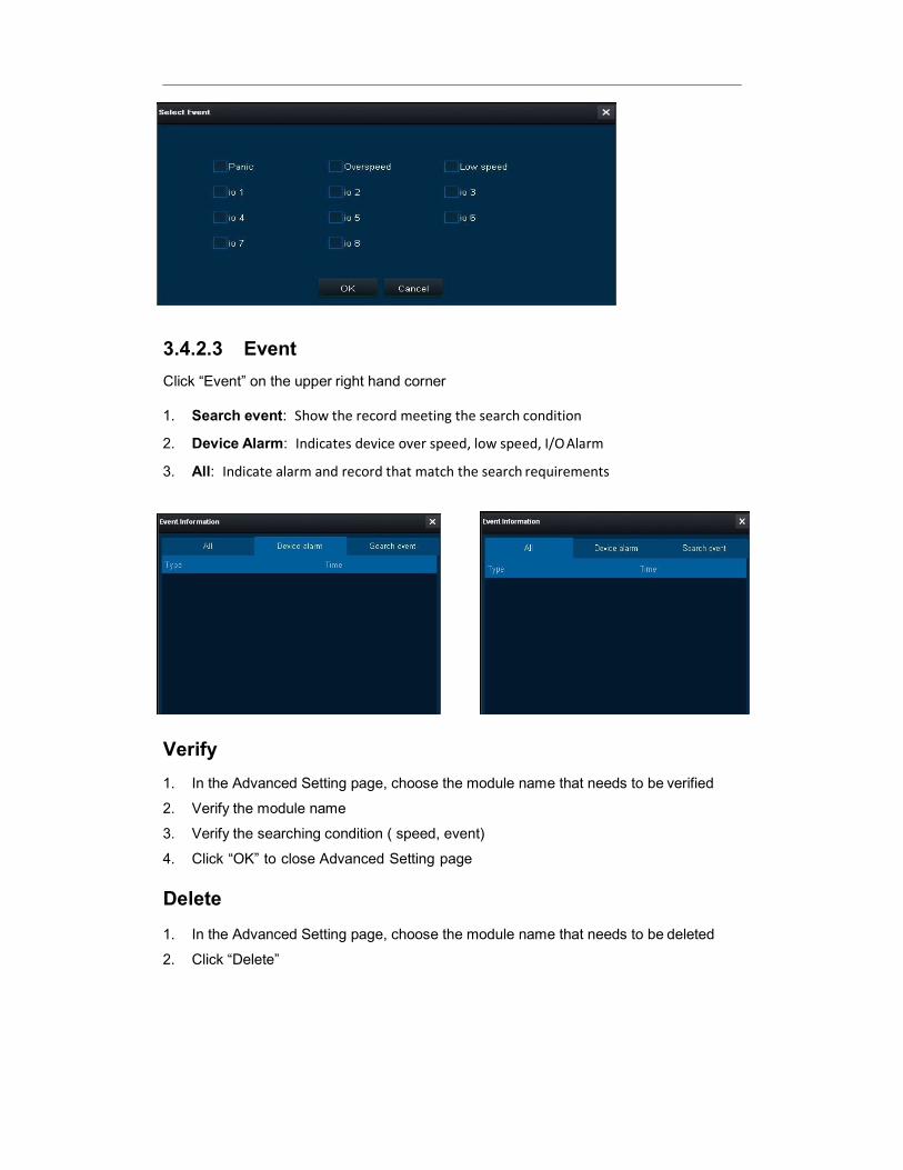
3.4.2.3 Event
Click “Event” on the upper right hand corner
1. Search event: Show the record meeting the search condition
2. Device Alarm: Indicates device over speed, low speed, I/O Alarm
3. All: Indicate alarm and record that match the search requirements
Verify
1. In the Advanced Setting page, choose the module name that needs to be verified
2. Verify the module name
3. Verify the searching condition ( speed, event)
4. Click “OK” to close Advanced Setting page
Delete
1. In the Advanced Setting page, choose the module name that needs to be deleted
2. Click “Delete”

3.5.1 User Permission / Add User
XDR allows multiple users to be added to the program for different levels of authorization
Add Users
1. Click the button “Add”, then the dialog pop up
2. Input the user name, password, and verify password
3. Select permissions
4. Click “OK

3.5.1.2 System Setting
Click at the top right corner of software to have system setting.
Screenshot Path Setting
Setup a path for screenshot of real-time review and playback. (server playback, hard disk
playback, remote device playback and directory playback)
Map Type Switch
Set the map for real-time review, playback and evidence center. (server playback, hard
disk playback, remote device playback and directory playback)
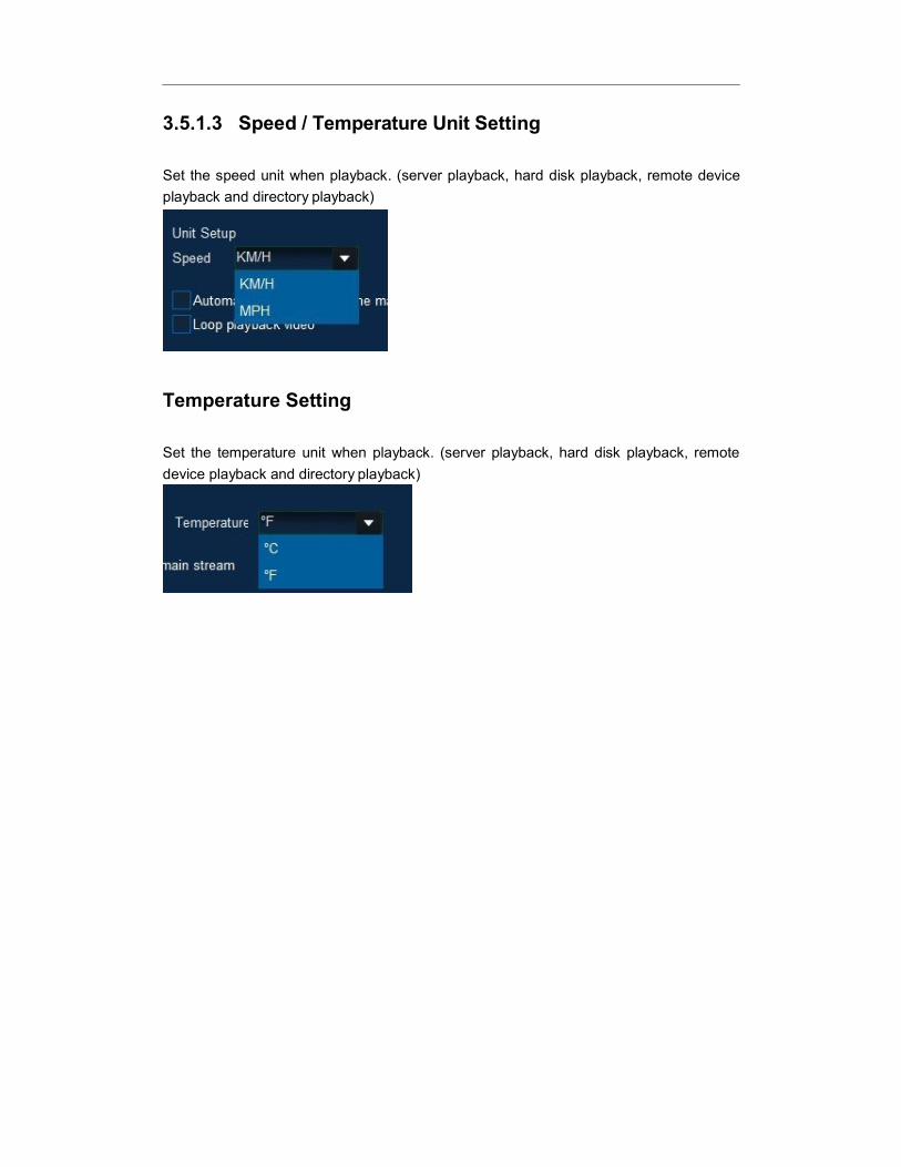
3.5.1.3 Speed / Temperature Unit Setting
Set the speed unit when playback. (server playback, hard disk playback, remote device
playback and directory playback)
Temperature Setting
Set the temperature unit when playback. (server playback, hard disk playback, remote
device playback and directory playback)

32
Technical Specification
Function Overview Preview, Recording, Playback, Route History
System OS Linux 2.6.24
Control Mode IR remote control
Video
Input 4 channels
Output 1 channels
Video System NTSC/PAL optional
Audio
Input 4 channels
Output 1 channel
Display
Display Split 1/4
OSD GPS information, alarm, temperature, voltage, device information, firmware version
Operation Interface Semi-transparent GUI
Recording
Video/Audio Compression H.264/ADPCM
Image Resolution PAL: D1(704x576), HD1(704x288), CIF(352x288) NTSC: D1(704x480), HD1(704x240), CIF(352x240)
Image Quality 1~8 levels adjustable (1 is the best)
Recording Mode Manual/schedule/Alarm (sensor trigger, speed, acceleration, video loss, temperature)
Post-recording Maximum 30 minutes
Mirror Recording Yes (Using one of the two SD Cards)
Playback & Backup
Playback Channel 1 channel by local playback, 1/4 channel by software playback
Search Mode Date/time, channel, file type
GPS GPS location tracking, speed detection and time sync
Storage SD Card 32GB/64GB/128GB Class 10 SDHC card – Max 128GB per slot
Interface
USB USB 2.0 × 1
SD SD × 2
Sensor 4 inputs, 2 outputs
Speed 1 channel pulse speed detection
Power
Input DC8-36V
Output 500mA@12V
Current Impulse current: input [email protected] Working current: input [email protected], [email protected] Standby current: 0A

33
VENTRA LIMITED WARRANTY
Ventra Technology warrants the system against defects in material and workmanship for a
period of one (1) year from the date of original purchase. During this period, Ventra’s liability
for any defective product, or any product part, shall be limited to the repair or replacement of
the product, at Ventra’s sole discretion.
This warranty does not apply to defects or damages resulting from mishandling, accident,
abuse, negligence, lightning, water/liquid, power surges, improper interfacing, operation
outside of design limits, misapplication, improper repair, or unauthorized modification.
The term "Ventra Product" is limited to the hardware components and required firmware. It
DOES NOT include software applications or programs, non-Ventra products or peripherals. To
the extent permitted by local law, all non-Ventra products or non-Ventra branded peripherals -
such as external storage SD card are provided provide
the respective manufacturer's own warranties directly to you, and are not covered by this
Limited Warranty.
To obtain service within the warranty period, please contact Ventra at (888) 418 3833 or
[email protected] for assistance. If product repair or replacement is necessary, a Return
Merchandise Authorization (RMA) will be issued. The Customer will be solely responsible for
shipping charges, insurance and proper packaging to prevent breakage in transit, whether or
not the product is covered by this warranty. All shipments of repaired or replaced products by
Ventra will be F.O.B. California.
VENTRA MAKES NO OTHER WARRANTIES, EXPRESS OR IMPLIED, AS TO MERCHANTABILITY OR
FITNESS FOR A PARTICULAR PURPOSE OF ANY PRODUCT SOLD UNDER THIS CONTRACT.
UNDER NO CIRCUMSTANCES SHALL VENTRA BE LIABLE FOR ANY INDIRECT, INCIDENTAL,
SPECIAL, PUNITIVE OR CONSEQUENTIAL DAMAGES INCLUDING, WITHOUT LIMITATION,
INFRINGEMENT OF THIRD PARTY RIGHTS, LOST GOODWILL, LOST REVENUES OR PROFITS,
WORK STOPPAGE, DATA LOSS, SYSTEM FAILURE, IMPAIRMENT OF OTHER GOODS, COSTS OF
REMOVAL AND REINSTALLATION OF THE SYSTEM, LOSS OF USE, INJURY TO PERSONS OR
PROPERTY ARISING OUT OR RELATED TO THE SYSTEM WHETHER BASED ON BREACH OF
WARRANTY, BREACH OF CONTRACT, TORT OR OTHERWISE. IN NO EVENT SHALL VENTRA’s
LIABILITY EXCEED THE ACTUAL PURCHASE PRICE OF THE SYSTEM WITH RESPECT TO WHICH
ANY CLAIM IS MADE.
The information in this specification sheet reflects the current technical specifications at the
time of print. Ventra reserve the right to change the technical or physical specifications and
features without prior notification.
While every effort has been made to ensure the accuracy of the information, certain
specifications are based on approximate figures
All trademarks, service marks, trade names, product names and logos are the property of their
respective owners.
Copyright 2015. Ventra Technology Inc. www.ventrainc.com [email protected]