Ventosa Especial Da Smc
120
Series ZP2 New New Vacuum Pad More shapes and sizes of pads. Applicable for various types of work pieces Compact, Space-saving ø0.8 to ø15 P. 1 to 9 ø5 to ø30 P. 10 to 12 ø2 to ø46 P. 13 to 16 3.5 x 7 to 8 x 30 P. 17 to 23 ø2 to ø8 P. 24 Thin Flat/Flat hin Flat/Flat Thin Flat/Flat For sheets or vinyl Bellows ellows Bellows For spherical work pieces or work pieces with inclined surface Oval val Oval For work pieces with bumps For stage setting of disks (CD, DVD) or glass substrates Can restrict the reduction of vacuum pressure even when there is no workpiece. Ball Spline Buffer all Spline Buffer Ball Spline Buffer Ball spline guide is used to the buffer. ø4 to ø125 P. 25 to 29 Mark-free ark free Mark-free For use where adsorption marks must not be left on work pieces. Sponge ponge Sponge Compact/Short/Nozzle ompact Short Nozzle Compact/Short/Nozzle ø4 to ø15 P. 30 to 32 Heavy-duty eavy duty Heavy-duty ø32 to ø340 P. 33 to 58 Special Configuration pecial Configuration Special Configuration P. 59, 60 Vacuum Saving Valve acuum Saving Valve Vacuum Saving Valve P. 61 to 64 For heavy or large work pieces For rectangular work pieces CAT.ES100-76A
-
Upload
demetriosctb1868 -
Category
Documents
-
view
224 -
download
0
Transcript of Ventosa Especial Da Smc

8/12/2019 Ventosa Especial Da Smc
http://slidepdf.com/reader/full/ventosa-especial-da-smc 1/119
Series ZP2
NewNewVacuum PadMore shapes and sizes of pads. Applicable for various types of work pieces
Compact, Space-saving
ø0.8 to ø15 P. 1 to 9
ø5 to ø30 P. 10 to 12
ø2 to ø46 P. 13 to 16
3.5 x 7 to 8 x 30 P. 17 to 23
ø2 to ø8 P. 24
Thin Flat/Flathin Flat/FlatThin Flat/Flat
For sheets or vinyl
BellowsellowsBellows
For spherical work pieces or work pieces with inclined surface
OvalvalOval
For work pieces with bumps
For stage setting of disks (CD, DVD)or glass substrates
Can restrict the reduction of vacuum pressure evenwhen there is no workpiece.
Ball Spline Bufferall Spline BufferBall Spline Buffer
Ball spline guide is used to the buffer.
ø4 to ø125 P. 25 to 29Mark-freeark freeMark-free
For use where adsorption marks must not be left on work pieces.
SpongepongeSponge
Compact/Short/Nozzleompact Short NozzleCompact/Short/Nozzle
ø4 to ø15 P. 30 to 32
Heavy-dutyeavy dutyHeavy-duty ø32 to ø340 P. 33 to 58
Special Configurationpecial ConfigurationSpecial Configuration P. 59, 60
Vacuum Saving Valveacuum Saving ValveVacuum Saving Valve P. 61 to 64
For heavy or largework pieces
For rectangularwork pieces
CAT.ES100-76A

8/12/2019 Ventosa Especial Da Smc
http://slidepdf.com/reader/full/ventosa-especial-da-smc 2/119

8/12/2019 Ventosa Especial Da Smc
http://slidepdf.com/reader/full/ventosa-especial-da-smc 3/119
Type
U
C
UT
B
P. 10
SymbolVariations
Pad
DiameterAdapter type Page
ø6, ø7, ø8
ø5, ø6
ø6, ø8
ø3, ø4
Flat
Nozzle ø0.8, ø1.1
ø5, ø6, ø11
ø14, ø18ø20
Thin flat(Skirt)
Compact Pad
Nozzle Pad
Thin Flat Pad
Series ZPSeries ZP2
Series ZP
Common adapter
Series ZP
Common adapter
UT
AN
P. 2
P. 1
P. 1
P. 1
P. 1
P. 5
P. 8
P. 9
MU
EU
AU
ø2, ø3.5, ø4
ø5, ø6, ø8
ø10, ø15
ø2, ø4, ø6
ø8, ø15
ø2, ø3, ø4
ø6, ø8
Short-type Pad
FlatFor adsorption of general
work piecesFor adsorption of workpieces with flat and notdeformed surfaceFlat with rib
For a workpiece which islikely to deform or forreleasing a workpiece cer-tainlyThin flat
For a workpiece which islikely to deformBellows
For adsorption of workpieces with inclined surface
Space-saving in the heightdirection
For adsorption of softwork pieces such as thin
sheets or vinyl. Wrinklingor deformation duringadsorption is reduced.
Series Variations
Flat
Flat with rib
Thin flat
Bellows
For adsorptionof small compo-nents such as ICchips
With adapterSingle unit
Single unit
Single unit
With adapterSingle unit
With adapterSingle unit
Single unit
Single unit
Single unit
Single unit
Front matter 3

8/12/2019 Ventosa Especial Da Smc
http://slidepdf.com/reader/full/ventosa-especial-da-smc 4/119
Bellows
(Multistage type)J P. 13
P. 14
P. 16
ø6, ø9, ø10
ø14, ø15
ø16, ø25
ø30
Bellows
MB
ø4, ø6, ø8
ø10, ø15
ø20
ZJø2, ø4, ø5
ø6, ø40, ø46
Bellows Pad
Series ZP
Common adapter
For use where there is nospace for the buffer(spring type). For adsorp-tion of work pieces withinclined surface
TypeSymbolVariations
Pad
DiameterAdapter type Page
Series Variations
P. 11Thin flat
(With groove)
ø10, ø15
ø20, ø25
ø30
Flat Pad
MTFor adsorption of flexible
sheets or film. Deformation
of the flat surface duringadsorption is reduced.
With adapterSingle unit
Single unit
Single unit
With adapterSingle unit
Front matter 4

8/12/2019 Ventosa Especial Da Smc
http://slidepdf.com/reader/full/ventosa-especial-da-smc 5/119
Flat
Flat with rib
Bellows
U
C
B
J
MU
EU
MT
MB
P. 1
P. 1
P. 1
P. 13
P. 2
P. 5
P. 11
P. 14
ø6, ø8
ø6, ø8
ø4
Flat
Thin flat
(With groove)
ø2, ø3.5, ø4
ø5, ø6, ø8
ø10, ø15
ø2, ø4, ø6
ø10, ø15ø20, ø25
ø30
ø4, ø6, ø8ø10, ø15
ø20Bellows
Series ZP
Common adapter
Flat
ø10, ø15ø25, ø30
Bellows
(Multistage type)
Blast-type Pad
VariationsPad
Series Variations
Blast treatment to createfinely uneven surface for
adsorption. Work piecescan be removed easily.
TypeSymbol DiameterAdapter type Page
Single unit
With adapterSingle unit
With adapterSingle unit
Single unit
With adapterSingle unit
Series ZPSeries ZP2
Single unit
Single unit
With adapterSingle unit
Front matter 5

8/12/2019 Ventosa Especial Da Smc
http://slidepdf.com/reader/full/ventosa-especial-da-smc 6/119
OvalW
3.5 x 7
4 x 105 x 106 x 10
4 x 205 x 206 x 208 x 20
4 x 30
5 x 306 x 308 x 30
Series ZP
Common adapter
ø2, ø4
ø6, ø8
FlatU
Oval Pad
Pad with BallSpline Buffer
For work pieces withlimitations on the adsorp-
tion surface
Ball spline guide is usedto the buffer.
Series Variations
Single unit
P. 17
P. 18
P. 19
P. 21
P. 23
P. 24
With adapter: Vacuuminlet direction Vertical
With adapter: Vacuuminlet direction Lateral
With buffer: Vacuuminlet direction Lateral
With buffer: Vacuuminlet direction Vertical
With buffer: Vacuuminlet direction Vertical
TypeSymbolVariations
Pad
DiameterAdapter type Page
Front matter 6

8/12/2019 Ventosa Especial Da Smc
http://slidepdf.com/reader/full/ventosa-especial-da-smc 7/119
Series ZPSeries ZP2 Series Variations
P. 27
P. 28
P. 29
P. 30
P. 31
P. 33
P. 35
P. 36
P. 33
FlatU
ø4, ø6, ø8
ø10, ø16ø25, ø32ø40, ø50
Sponge
Heavy-duty
(Thin flat with rib)
ø32, ø300ø340
ø150, ø250
ø32, ø150Heavy-duty
(Bellows)
Heavy-duty
(Oval)30 x 50
Mark-free Pad
Resin Attachment
Sponge Pad
Heavy-duty Pad
Series ZP
Common adapter
Heavy-duty
(Flat with rib)
Bellows
H
S
H
HT
—
ø40, ø50ø63, ø80ø100, ø125
Heavy-duty
(Flat with rib)
ø4, ø6ø8, ø10
ø15
ø6, ø8
ø10, ø13
ø16, ø20
ø25, ø32
HB
HW
—
—
For use where adsorptionmarks must not be left onwork pieces.
Mark-free.Prevents sticking
of the rubber and
the workpiece.
For adsorption of workpieces with bumps
For heavy or large workpieces
Single unit
With padSingle unit
Single unit
With adapter
Single unitNo trace on the object
Clear trace of the pad
Mark-free pad
Standard pad
Mark-free NBR pad
Stuck fluororesin pad
AttachmentSeries ZP
Common adapter
P. 25Cyclone Pad (Non-contact pad)
Made to Order Related Pad
TypeSymbolVariations
Pad
DiameterAdapter type Page
Front matter 7

8/12/2019 Ventosa Especial Da Smc
http://slidepdf.com/reader/full/ventosa-especial-da-smc 8/119
Heavy-dutyBall Joint Pad
For adsorption of workpieces with inclined orcurved surface
Series Variations
TypeSymbolVariations
Pad
DiameterPage
P. 37
P. 38
P. 41
P. 43
P. 44
P. 45
P. 47
P. 39
Heavy-duty
(Flat with rib)H
ø40
ø50
ø63
ø80
ø100ø125
ø40ø50ø63
ø80
ø100
ø125
Heavy-duty
(Bellows)HB
With adapter: Vacuuminlet direction Vertical
With buffer: Vacuuminlet direction Vertical
With adapter: Vacuuminlet direction Lateral
With buffer: Vacuum
inlet direction Lateral
With buffer: Vacuuminlet direction Vertical
With buffer: Vacuuminlet direction Lateral
With adapter: Vacuuminlet direction Vertical
With adapter: Vacuuminlet direction Lateral
Front matter 8

8/12/2019 Ventosa Especial Da Smc
http://slidepdf.com/reader/full/ventosa-especial-da-smc 9/119

8/12/2019 Ventosa Especial Da Smc
http://slidepdf.com/reader/full/ventosa-especial-da-smc 10/119
Vacuum Pad Selection Procedures
Points for Selecting Vacuum Pads
A. Theoretical Lifting Force
B. Shear Force and Moment Applied to Vacuum Pad
Lifting Force and Vacuum Pad Diameter
1. Theoretical Lifting Force
Vacuum Pad Type
Vacuum Pad Material
Rubber Material and Properties
Color and Identification
Buffer Attachment
Pad Selection by Work Type
Vacuum Pad Durability
Calculating Vacuum Ejector and Switching Valve Size with the Formula
Leakage volume from Conductance of Work
Leakage volume from Adsorption Test
Relationship between Vacuum Pressure and Response Time after Supply Valve (Switching Valve) is Operated
Calculating Adsorption Response Time with the Formula
Adsorption Response Time from the Selection Graph
Safety Measures
Precautions on Vacuum Equipment Selection
Vacuum Ejector or Pump and Number of Vacuum Pads
Vacuum Ejector Selection and Handling Precautions
Supply Pressure of Vacuum Ejector
Timing for Vacuum Generation and Suction Verification
A. Timing for Vacuum Generation
B. Suction Verification
C. Set Pressure for Vacuum Pressure Switch
Dust Handling of Vacuum Equipment
Transfer of Semiconductor Chips
Selection Graph
Glossary of Terms
Countermeasures for Vacuum Adsorption System Problems (Troubleshooting)
Non-conformance Examples
Time of Replacement of Vacuum Pad
Features of Vacuum Adsorption1 Front matter 11
Selection of Vacuum Ejector and Vacuum Switching Valve3 Front matter 17
Leakage Volume during Work Adsorption4 Front matter 17
Adsorption Response Time5 Front matter 18
Precautions on Vacuum Equipment Selection and SMC’s Proposal6 Front matter 20
Vacuum Equipment Selection Example7 Front matter 24
Data8 Front matter 25
Vacuum Pad Selection2 Front matter 11
Vacuum Equipment
Model Selection
Front matter 10

8/12/2019 Ventosa Especial Da Smc
http://slidepdf.com/reader/full/ventosa-especial-da-smc 11/119
Vacuum adsorption system as a method to hold a workpiece has the following features.
• Easy construction
• Compatible with any place where adsorption is possible.
• No need for accurate positioning
• Compatible with soft and easily-deformed work pieces
However, special care is required in the following conditions.
• Workpiece may drop under certain conditions since it is transferred being adsorbed.
• Liquid or foreign matter around the workpiece may be sucked into the equipment.
• Large adsorption area is necessary to get large gripping force.
• Vacuum pad (rubber) may deteriorate.
Fully understand the features above and select the equipment that suits your operating conditions.
Vacuum Pad Selection Procedures
1) Fully taking into account the balance of a workpiece, identify the adsorption positioning, number of pads and applicable pad
diameter (or pad area).
2) Find the theoretical lifting force from the identified adsorption area (pad area x number of pads) and vacuum pressure, and
then find the lifting force considering actual lifting and safety factor of transfer condition.
3) Determine a pad diameter (or pad area) that is sufficient to ensure the lifting force is greater than the workpiece mass.
4) Determine the pad type and materials, and the necessity of buffer based on the operating environment, and the workpiece
shape and materials.
The above shows selection procedures for general vacuum pads; thus, they will not be applicable for all pads. Customers are
required to conduct a test on their own and to select applicable adsorption conditions and pads based on the test results.
Points for Selecting Vacuum Pads
A. Theoretical Lifting Force
• The theoretical lifting force is determined by vacuum pressure and contact area of the vacuum pad.
• Since the theoretical lifting force is the value measured at the static state, the safety factor responding to the actual
operating conditions must be estimated in the actual operation.
• It is not necessarily true that higher vacuum pressure is better. Extremely high vacuum pressure may cause problems.
• When the vacuum pressure is unnecessarily high, pads are likely to be worn out quickly and cracked, which makes the
pad service life shorter.
Doubling the vacuum pressure makes the theoretical lifting force double, while to doubling the pad diameter makes the
theoretical lifting force quadruple.
• When the vacuum pressure (set pressure) is high, it makes not only response time longer, but also the necessary energy
to generate a vacuum larger.
Example) Theoretical lifting force = Pressure x Area
Pad diameterArea (cm2)
Vacuum pressure[40-kPa]
Vacuum pressure[80-kPa]
ø20
ø40
3.14
12.56
Theoretical lifting force12.56 N
Theoretical lifting force50.23 N
Theoretical lifting force25.11 N
Theoretical lifting force100.45 N
4 times
2 times
Features of Vacuum Adsorption1
Vacuum Pad Selection2
Front matter 11
Model Selection
8/12/2019 Ventosa Especial Da Smc
http://slidepdf.com/reader/full/ventosa-especial-da-smc 12/119
B. Shear Force and Moment Applied to Vacuum Pad
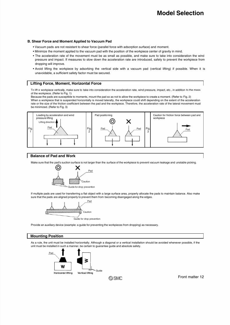
• Vacuum pads are not resistant to shear force (parallel force with adsorption surface) and moment.
• Minimize the moment applied to the vacuum pad with the position of the workpiece center of gravity in mind.
• The acceleration rate of the movement must be as small as possible, and make sure to take into consideration the wind
pressure and impact. If measures to slow down the acceleration rate are introduced, safety to prevent the workpiece from
dropping will improve.
• Avoid lifting the workpiece by adsorbing the vertical side with a vacuum pad (vertical lifting) if possible. When it is
unavoidable, a sufficient safety factor must be secured.
To lift a workpiece vertically, make sure to take into consideration the acceleration rate, wind pressure, impact, etc., in addition to the mass
of the workpiece. (Refer to Fig. 1)
Because the pads are susceptible to moments, mount the pad so as not to allow the workpiece to create a moment. (Refer to Fig. 2)
When a workpiece that is suspended horizontally is moved laterally, the workpiece could shift depending on the extent of the accelerationrate or the size of the friction coefficient between the pad and the workpiece. Therefore, the acceleration rate of the lateral movement must
be minimized. (Refer to Fig. 3)
Lifting Force, Moment, Horizontal Force
Loading by acceleration and windpressure lifting
Pad positioning Caution for friction force between pad andworkpiece
Fig.1
Fig.2
Fig.3
Pad
Lifting direction
Pad Pad Pad
Guide
Make sure that the pad's suction surface is not larger than the surface of the workpiece to prevent vacuum leakage and unstable picking.
Balance of Pad and Work
As a rule, the unit must be installed horizontally. Although a diagonal or a vertical installation should be avoided whenever possible, if the
unit must be installed in such a manner, be certain to guarantee guide and absolute safety.
Mounting Position
If multiple pads are used for transferring a flat object with a large surface area, properly allocate the pads to maintain balance. Also make
sure that the pads are aligned properly to prevent them from becoming disengaged along the edges.
Provide an auxiliary device (example: a guide for preventing the workpieces from dropping) as necessary.
Caution
Guide for drop prevention
Pad
Caution
Guide for drop prevention
Pad
Pad
Horizontal lifting Vertical lifting
Front matter 12
Model Selection

8/12/2019 Ventosa Especial Da Smc
http://slidepdf.com/reader/full/ventosa-especial-da-smc 13/119
Pad diameter (mm) ø80.50
ø10 ø13 ø16 ø20 ø25 ø32 ø40 ø50Pad area S (cm2) 0.79 1.33
ø20.03
ø4 ø60.13 0.28 2.01 3.14 4.91 8.04 12.6 19.6
Vacuum
pressure(kPa)
(N)
–85
– 80– 75– 70– 65– 60– 55– 50– 45– 40
0.27
0.250.24
0.22
0.20
0.19
0.17
0.16
0.14
0.13
1.07
1.000.94
0.88
0.82
0.75
0.69
0.63
0.57
0.50
2.40
2.262.12
1.98
1.84
1.70
1.55
1.41
1.27
1.13
4.27
4.023.77
3.52
3.27
3.01
2.76
2.51
2.26
2.01
6.67
6.285.89
5.50
5.10
4.71
4.32
3.93
3.53
3.14
11.3
10.610.0
9.3
8.6
8.0
7.3
6.7
6.0
5.3
17.1
16.115.1
14.1
13.1
12.1
11.1
10.0
9.0
8.0
26.7
25.123.6
22.0
20.4
18.8
17.3
15.7
14.1
12.6
41.7
39.336.8
34.3
31.9
29.4
27.0
24.5
22.1
19.6
68.3
64.360.3
56.3
52.2
48.2
44.2
40.2
36.2
32.2
107
10195
88
82
76
69
63
57
50
167
157147
137
127
118
108
98
88
78
Pad diameter (mm) ø125122.7
ø150 ø250 ø300 ø340Pad area S (cm2) 176.6
ø6331.2
ø80 ø10050.2 78.5 490.6 706.5 907.5
Vacuumpressure
(kPa)
–85– 80
– 75– 70– 65– 60– 55– 50– 45– 40
265
250
234218
203
187
172
156
140
125
427
402
377351
326
301
276
251
226
201
667
628
589550
510
471
432
393
353
314
1043
982
920 859
798
736
675
614
552
491
1501
1413
13251236
1148
1060
971
883
795
706
4170
3925
36803434
3189
2944
2698
2453
2208
1962
6005
5652
52994946
4592
4239
3886
3533
3179
2826
7714
7260
68066353
5899
5445
4991
4538
4084
3630
Pad size (mm)
0.44Pad area S (cm2) 0.52 0.76
2 x 40.07
3.5 x 7 4 x 10 5 x 10 6 x 10 4 x 20 5 x 20 6 x 20 8 x 20 4 x 30 5 x 30 6 x 30 8 x 300.21 0.36 0.94 1.12 1.46 1.16
Vacuumpressure
(kPa)
–85– 80– 75
–
70– 65– 60– 55– 50– 45– 40
0.60
0.56
0.53
0.490.46
0.42
0.39
0.35
0.32
0.28
1.79
1.68
1.58
1.471.37
1.26
1.16
1.05
0.95
0.84
3.06
2.88
2.70
2.522.34
2.16
1.98
1.80
1.62
1.44
3.74
3.52
3.30
3.082.86
2.64
2.42
2.20
1.98
1.76
4.42
4.16
3.90
3.643.38
3.12
2.86
2.60
2.34
2.08
6.46
6.08
5.70
5.324.94
4.56
4.18
3.80
3.42
3.04
7.99
7.52
7.05
6.586.11
5.64
5.17
4.70
4.23
3.76
9.52
8.96
8.40
7.847.28
6.72
6.16
5.60
5.04
4.48
12.41
11.68
10.95
10.22 9.49
8.76
8.03
7.30
6.57
5.84
9.86
9.28
8.70
8.127.54
6.96
6.38
5.80
5.22
4.64
1.44
12.24
11.52
10.80
10.08 9.36
8.64
7.92
7.20
6.48
5.76
1.72
14.62
13.76
12.90
12.0411.18
10.32
9.46
8.60
7.74
6.88
2.26
19.21
18.08
16.95
15.8214.69
13.56
12.43
11.30
10.17
9.04
(N)
(N)
(1) Theoretical Lifting Force (Theoretical lifting force = P x S x 0.1)
Pad Diameter (ø2 to ø50)
Pad Diameter (ø63 to ø340)
Oval Pad (2 x 4 to 8 x 30)
The theoretical lifting force of a pad can be found by calculation or from the theoretical lifting force table.
Calculation
: Lifting force (N): Vacuum pressure (kPa): Pad area (cm2): Safety factor Horizontal lifting: 4 or more Vertical lifting: 8 or more
W = P x S x 0.1 x –1t
WPSt
The theoretical lifting force (not including the safety factor) is found from the pad diameter and vacuum pressure.The required lifting force is then found by dividing the theoretical lifting force by the safety factor t.
Lifting force = Theoretical lifting force ÷ t
Theoretical Lifting Force
Horizontal lifting Vertical lifting
This type of application shouldbasically be avoided.
Pad
Front matter 13
Model Selection
Lifting Force and Vacuum Pad Diameter
1. Theoretical Lifting Force
• Set the vacuum pressure below the pressure that has been stabilized after adsorption.
• However, when a workpiece is permeable or has a rough surface, note that the vacuum pressure drops since the workpiece
takes air in. In such a case, carry out an adsorption test for confirmation.
• The vacuum pressure when using an ejector is approximately –60 kPa as a guide.

8/12/2019 Ventosa Especial Da Smc
http://slidepdf.com/reader/full/ventosa-especial-da-smc 14/119
ApplicationMaterial
NBR Transfer of general work, Corrugated board, Veneer plate, Iron plate and others
Silicone rubber Semiconductor, Removing from die-casting, Thin work, Food processor
Urethane rubber Corrugated board, Iron plate, Veneer plate
FKM Chemical work
Conductive NBR General work of semiconductor (Static electricity resistance)
Conductive silicone rubber Semiconductor (Static electricity)
ApplicationPad shape
Flat
Flat with rib
Deep
Bellows
Oval
ApplicationPad shape
Ball joint
Long stroke buffer
Large
Conductive
Pad Type
Vacuum Pad Type
• Vacuum pads are available in flat, deep, bellows, thin flat, with rib, and oval types, etc. Select the optimal shape in
accordance with the workpiece and operating environment. Please contact SMC for shapes not included in this catalog.
To be used when work is curved shape.
To be used when adsorption surface ofwork is flat and not deformed.
To be used when work is likely to deformor in the case of releasing work certainly.
To be used when there is not enoughspace to install buffer or adsorptionsurface of work is slanted.
To be used when work has limitedadsorption surface or long in length and
work is required to locate precisely.
To be used when work is heavy weight.
As one of the countermeasures againstthe static electricity, rubber material withreduced resistance is used.For antistatic measures
To be used when adsorption surface ofwork is not horizontal.
To be used when work height is not evenor cushioning toward work is required.
Vacuum Pad Material
• It is necessary to determine vacuum pad materials carefully taking into account the workpiece shape, adaptability in the
operating environment, effect after being adsorbed, electrical conductivity, etc.
• Based on the work transfer example for each material, select after confirming the characteristics (adaptability) of rubber.
Vacuum Pad/Example of Work Transfer
Material
Front matter 14
Model Selection
8/12/2019 Ventosa Especial Da Smc
http://slidepdf.com/reader/full/ventosa-especial-da-smc 15/119
Main features
Pure gum property(specific gravity)
Impact resilience
Abrasion resistance
Tear resistance
Flex crack resistance
Heat aging
Weather resistance
Ozone resistance
Gasoline/Gas oil
Benzene/Toluene
Alcohol
Ether
Ketone (MEK)
Ethyl acetate
Water
Organic acid
Strong alkali
Weak alkali
1.00-1.20
120
0
—
× /
× /
×
× /
× /
/
0.95-0.98
× /
× /
× /
200
–30
—
× /
× /
×
× /
1.00-1.30
60
0
—
× /
× /
×
×
× /
×
×
×
×
1.80-1.82
250
0
—
× /
/
× /
×
×
/
0.86-0.87
150
–20
—
× /
×
×
×
1.00-1.20
100
0
104 or less
× /
× /
×
× /
× /
/
0.95-0.98
× /
× /
× /
200
–10
104 or less
× /
× /
×
× /
P h y s
i c a
l p r o p e r t i e s o
f b l e n
d e d g u m
C h e m
i c a
l r e s
i s t a n
c e
O i l r e s
i s t a n c e
A
l k a
l i n e r e s
i s t a n c e
A c
i d r e s
i s t a n c e
NBR(Nitrilerubber)
Siliconerubber
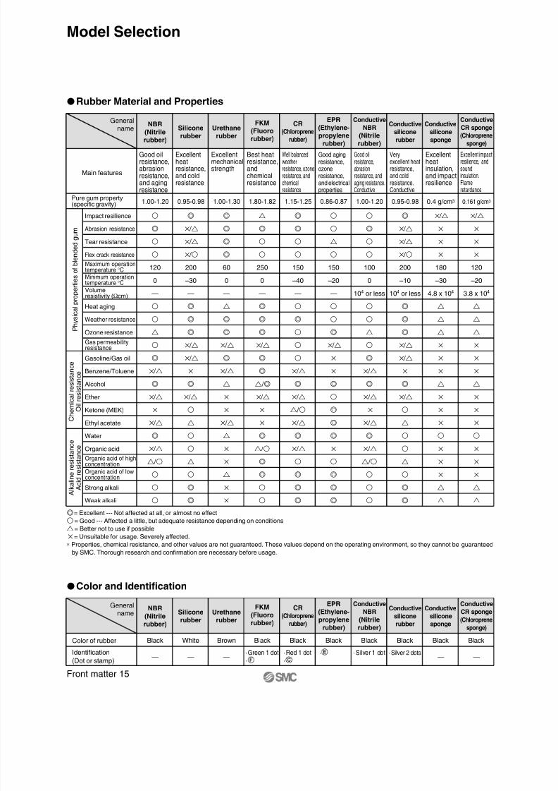
= Excellent --- Not affected at all, or almost no effect
= Good --- Affected a little, but adequate resistance depending on conditions
= Better not to use if possible
× = Unsuitable for usage. Severely affected.
∗ Properties, chemical resistance, and other values are not guaranteed. These values depend on the operating environment, so they cannot be guaranteed
by SMC. Thorough research and confirmation are necessary before usage.
Good oilresistance,abrasionresistance,and agingresistance
Excellentheatresistance,and coldresistance
Urethanerubber
Excellentmechanicalstrength
FKM(Fluororubber)
Best heatresistance,andchemicalresistance
EPR(Ethylene-propylene
rubber)
Good agingresistance,ozoneresistance,and electricalproperties
ConductiveNBR
(Nitrilerubber)
Good oilresistance,abrasionresistance, andaging resistance.Conductive
Conductivesilicone
rubber
Veryexcellent heatresistance,and coldresistance.Conductive
0.161 g/cm3
× /
×
×
×
120
–20
3.8 x 10⁴
×
×
×
×
×
×
×
×
×
ConductiveCR sponge
(Chloroprene
sponge)
Excellent impactresilience, andsoundinsulation.Flameretardance
0.4 g/cm3
× /
×
×
×
180
–30
4.8 x 10⁴
×
×
×
×
×
×
×
×
×
Conductivesilicone
sponge
Excellentheatinsulation,and impactresilience
Rubber Material and Properties
1.15-1.25
150
–40
—
× /
× /
/
× /
× /
CR(Chloroprene
rubber)
Well balancedweatherresistance, ozoneresistance, andchemicalresistance
General
name
Color and Identification
Color of rubber Black White Brown Black Black Black Black Black Black Black
— — —· Silver 1 dot · Silver 2 dots
— —· Green 1 dot·
· Red 1 dot·
·
Maximum operationtemperature °CMinimum operationtemperature °CVolumeresistivity (Ωcm)
Gas permeabilityresistance
Organic acid of highconcentration
Organic acid of lowconcentration
Identification
(Dot or stamp)
Generalname
Front matter 15
Model Selection
NBR
(Nitrilerubber)
Siliconerubber
Urethanerubber
FKM
(Fluororubber)
EPR(Ethylene-propylene
rubber)
Conductive
NBR
(Nitrilerubber)
Conductive
siliconerubber
Conductive
CR sponge
(Chloroprene
sponge)
Conductive
siliconesponge
CR
(Chloroprenerubber)

8/12/2019 Ventosa Especial Da Smc
http://slidepdf.com/reader/full/ventosa-especial-da-smc 16/119
If a soft workpiece such as vinyl, paper, or thin sheet is picked up,
the vacuum pressure could cause the workpiece to deform or
wrinkle. In such a case, it will be necessary to use a small pad or a
ribbed pad and reduce the vacuum pressure.
3. Soft Work
When pushing a pad to a workpiece, make sure not to apply animpact or a large force which would lead to premature deformation,cracking, or wearing of the pad. The pad should be pushed against
the workpiece to the extent that its skirt portion deforms or that itsribbed portion comes into slight contact with the workpiece.Especially, when using a smaller diameter pad, make sure to locateit correctly.
4. Impact to Pad
Pad
Vinyl, paper, etc.
Decide the positionnot to strike
Vacuum Pad Durability
• Need to be careful of the vacuum pad (rubber) deterioration.
• The vacuum pad’s adsorption surface will be worn out when it is used for a certain period of time, and the outer diameter
gradually becomes smaller. The lifting force becomes weaker as the pad diameter becomes smaller, but absorption is still
possible.
• Since the vacuum pad replacement period greatly varies depending on the operating environment, it is extremely difficult to
estimate the replacement period. Specify the period taking into account the actual operating conditions.
Front matter 16
Model Selection
Buffer Attachment
• Use a buffer when there is a variation in the height of work pieces and fragile work pieces are adsorbed (cushioning is
necessary). If it is necessary to further position the pad and the workpiece, use a non-rotating buffer.
If the pad and the workpiece cannot be positioned properly, such as when
picking a workpiece having an uneven height, use a built-in spring type pad
with a buffer. This type of pad acts as a cushion between the pad and the
workpiece. If it is necessary to further position the pad and the workpiece,
use a non-rotating buffer.
Unsteady Distance between Pad and Work
Pad
Pad
Pad Selection by Work Type
• Carefully select a pad for the following work pieces.
To pick a permeable workpiece such as paper, select a pad with a
small diameter that is sufficient to lift the workpiece. Because a
large amount of air leakage could reduce the pad’s suction force, it
may be necessary to increase the capacity of an ejector or vacuum
pump or enlarge the conductance area of the piping passage.
1. Porous Work
When a workpiece with a large surface area such as sheet glass
or PCB is suspended, the workpiece could move in a wavelike
motion if a large force is applied by wind pressure or by an impact.
Therefore, it is necessary to ensure the proper allocation and size
of pads.
2. Flat Plate Work
Porous work
Plate glass, circuit board, etc.

8/12/2019 Ventosa Especial Da Smc
http://slidepdf.com/reader/full/ventosa-especial-da-smc 17/119
Selection of Vacuum Ejector and Vacuum Switching Valve3
Leakage Volume during Work Adsorption4
ZH07BS, ZH07DS
Exhaust CharacteristicsFlow-rate CharacteristicsSupply pressure 0.45 MPa
V a c u u m
p r e s s u r e
( k P a
)
Supply pressure (MPa) Suction flow rate (L/min (ANR))
Suction flouction flow r ratete
a c u u m
p r e s s u r e
acuu
m pressure
A i r c
o n s u
m p t i o n
ir co
nsum
ption
Suction flow rate
V a c u u m
p r e s s u r e
A i r c
o n s u
m p t i o n
S u c
t i o n
f l o w
r a t e ( L / m i n ( A N R ) )
A i r c o n s u m
p t i o n
( L / m i n ( A N R ) )
V a c u u m
p r e s s u r e
( k P a
)
Calculating Vacuum Ejector and Switching Valve Size with the Formula
Average suction flow rate for achieving adsorption response time
Max. suction flow rate
Qmax = (2 to 3) x Q L/min (ANR)
<Selection Procedure>
• EjectorSelect the ejector with the greater maximum suction flow rate from the Qmax indicated above.
• Direct operation valve
∗ Select a valve (solenoid valve) having a conductance that is greater than that of the conductance C formula given above fromthe related equipment (page 1278 in Best Pneumatics No. 4).
Q : Average suction flow rate L/min (ANR)
V : Piping capacity (L)
T1 : Arrival time to stable Pv 63% after adsorption (sec)
T2 : Arrival time to stable Pv 95% after adsorption (sec)
QL : Leakage volume during work adsorption L/min (ANR) Note 1)
Q = ——— + QL
T2 = 3 x T1
V x 60
T1
Conductance C = ———— [dm3 / (s·bar)]Qmax5 x 11.1
Note 1) QL: 0 when no leakage occurs during adsorbing a workpiece.If there is leakage during adsorbing a workpiece, find the leakage volume based on “4. Leakage Volume during Work Adsorption.”
Note 2) Tube piping capacity can be found in “8. Data: Piping Capacity by Tube I.D. (Selection Graph (2)).”
Leakage Volume from Conductance of Work
Leakage Volume from Adsorption Test
Air could be drawn in depending on the type of workpiece. As a result,the vacuum pressure in the pad becomes reduced and the amount ofvacuum that is necessary for adsorption cannot be attained.
When this type of workpiece must be handled, it is necessary to selectthe proper size of the ejector and the vacuum switching valve by takinginto consideration the amount of air that could leak through the work-piece.
Leakage volume QL = 11.1 x 5 x CL
QL: Leakage volume L/min (ANR)CL: Conductance between work and pad, and work opening area [dm3 / (s·bar)]
As described in the illustration below, pick up the workpiece with the ejector, using an ejector, pad and a vacuum gauge.At this time, read vacuum pressure P1, obtain the suction flow rate from the flow-rate characteristics graph for the ejector that is being used,
and render this amount as the leakage of the workpiece.
PadPad
Ventilation work Rough work surface
Pad
Vacuum pressure: P1
Work
Exercise: Using a supply pressure of 0.45 MPa, when the ejector(ZH07S) picks up a workpiece that leaks air, the vacuum gaugeindicated a pressure of –53 kPa. Calculate the leakage volume
from the workpiece.
<Selection Procedure>
When obtaining the suction flow rate at a vacuum pressure of–53 kPa from the ZH07DS flow-rate characteristics graph, thesuction flow rate is 5 L/min (ANR).
Leakage volume ≈ Suction flow rate 5 L/min (ANR)
Front matter 17
Model Selection

8/12/2019 Ventosa Especial Da Smc
http://slidepdf.com/reader/full/ventosa-especial-da-smc 18/119
Adsorption Response Time5
When a vacuum pad is used for the adsorption transfer of a workpiece, the approximate adsorption response time can be ob-tained (the length of time it takes for the pad’s internal vacuum pressure to reach the pressure that is required for adsorption afterthe supply valve vacuum switching valve has been operated). An approximate adsorption response time can be obtained
through formulas and selection graphs.
Relationship between Vacuum Pressure and Response Time after Supply Valve (Switch-
ing Valve) is Operated
The relationship between vacuum pressure and response time after the supply valve (switching valve) is operated as shown below.
Vacuum System Circuit Vacuum Pressure and Response Time after SupplyValve (Switching Valve) is Operated
Supply valve
Pad
Switching valve
Work
Pad
Work
Pv: Final vacuum pressureT1 : Arrival time to 63% of final vacuum pressure PvT2 : Arrival time to 95% of final vacuum pressure Pv
Arrival time (sec)
V a c u u m p
r e s s u r e ( P )
Supply valve(Switching valve)
operation
Calculating Adsorption Response Time with the Formula
Adsorption response times T1 and T2 can be obtained through the formulas given below.
For the conductance, the equivalent conductance can be found in “8. Data: Conductance by Tube I.D. (Selection Graph (3)).”
T1 : Arrival time to 63% of final vacuum pressure Pv (sec)
T2 : Arrival time to 95% of final vacuum pressure Pv (sec)
Q1 : Average suction flow rate L/min [ANR]
Calculation of average suction flow rate• Ejector
Q1 = (1/2 to 1/3) x Ejector max. suction flow rate L/min [ANR]
• Vacuum pumpQ1 = (1/2 to 1/3) x 5 x 11.1 x Conductance of vacuum pump [dm
3 /(s·bar)]
D : Piping diameter (mm)L : Length from ejector and switch valve to pad (m)V : Piping capacity from ejector and switching valve to pad (L)Q2 : Max. flow from ejector and switching valve to pad by piping system
Q2 = C x 5 x 11.1 L/min [ANR]Q : Smaller one between the Q1 and Q2 L/min [ANR]C : Conductance of piping [dm
3 /(s·bar)]
Adsorption response time T1 = ———
Adsorption response time T2 = 3 x T1
Piping capacity
V = —— D2 x L x –––– (L)
V x 60Q
3.144
11000
Front matter 18
Model Selection

8/12/2019 Ventosa Especial Da Smc
http://slidepdf.com/reader/full/ventosa-especial-da-smc 19/119
Selection Graph (1) Adsorption Response Time
M a x .
s u c
t i o n
f l o w
r a t e Q
( L / m i n ( A N R ) )
Piping capacity
Arrival time of vacuum pressure (63%) T1 (sec)
Arrival time of vacuum pressure (95%) T2 (sec)
∗ Conversely, the size of the ejector or the size of the switching valve of the vacuum pump system can be obtained from the adsorption response time.
How to read the graphExample 1: For obtaining the adsorption response time until the pressure in the piping system with a piping capacity of 0.02 L isdischarged to 63% (T1) of the final vacuum pressure through the use of the vacuum ejector ZH07S with a maximum suction flow rate of 12L/min (ANR).
<Selection Procedure>
From the point at which the vacuum ejector’s maximum vacuum suction flow rate of 12 L/min (ANR) and the piping capacity of 0.02 Lintersect, the adsorption response time T1 that elapses until 63% of the maximum vacuum pressure is reached can be obtained. (Sequencein Selection Graph (1), ) T1 ≈ 0.3 seconds.
Example 2: For obtaining the discharge response time until the internal pressure in the 5 L tank is discharged to 95% (T2) of the finalvacuum pressure through the use of a valve with a conductance of 3.6 [dm3 /(s·bar)].
<Selection Procedure>
From the point at which the valve’s conductance of 3.6 [dm 3 /(s·bar)] and the pip ing capacity of 5 L intersect, the d ischarge response time (T2)that elapses until 95% of the final vacuum pressure is reached can be obtained. (Sequence in Selection Graph (1), ) T2 ≈ 12 seconds.
Front matter 19
Model Selection
Adsorption Response Time from the Selection Graph
1. Tube Piping CapacityPiping capacity from the ejector and switching valve at vacuum pump to the pad can be found in “8. Data: Piping Capacity byTube I.D. (Selection Graph (2)).”
2. Obtain the adsorption response times.By operating the supply valve (switching valve) that controls the ejector (vacuum pump), the adsorption response times T1 andT2 that elapsed before the prescribed vacuum pressure is reached can be obtained from the Selection Graph (1).
V a
l v e c o n
d u c
t a n c e =
Q
5 x
1 1
. 1 [ d m
3 / ( s
· b a r ) ]

8/12/2019 Ventosa Especial Da Smc
http://slidepdf.com/reader/full/ventosa-especial-da-smc 20/119
Vacuum Ejector or Pump and Number of Vacuum Pads
Ideally, one pad should beused for each ejector.
When more than one pad is attached to a singleejector, if one of the work pieces becomesdetached, the vacuum pressure will drop, causingother work pieces to become detached. Therefore,the countermeasures listed below must be taken.• Adjust the needle valve to minimize the
pressure fluctuation between adsorption andnon-adsorption operations.
• Provide a vacuum switching valve to eachindividual pad to minimize the influences onother pads if an adsorption error occurs.
Ideally, one pad should beused for each line.
When more than one pad is attached to a singlevacuum line, take the countermeasures listed below.• Adjust the needle valve to minimize the
pressure fluctuation between adsorption andnon-adsorption operation.
• Include a tank and a vacuum pressurereduction valve (vacuum pressure regulatorvalve) to stabilize the source pressure.
• Provide a vacuum switching valve to eachindividual pad to minimize the influences onother pads if an adsorption error occurs.
Vacuum line
Vacuum source
Precautions on Vacuum Equipment Selection and SMC’s Proposal6
Safety Measures
• Make sure to provide a safe design for a vacuum pressure drop due to a disruption of power supply, or a lack of supply air.
Drop prevention measures must be taken in particular when dropping a workpiece presents some degree of danger.
Precautions on Vacuum Equipment Selection
As a countermeasure for power outages,select a supply valve that is normallyopen or one that is equipped with a self-holding function.
Select a vacuum switching valve thathas a conductance that does not reducethe composite conductance consisting ofthe areas from the pad to the ejector.
For the release valve, select a 2/3 portvalve with a low vacuum specification.Also, use a needle valve to regulate therelease flow rate.
• During the adsorption and transfer of aworkpiece, verification of the vacuum switchis recommended.
• In addition, visually verify the vacuum
gauge when handling a heavy or a hazar-dous item.• The ZSP1 type is optimal for the adsorption
and transfer of small parts using a suctionnozzle with a small diameter.
• Install a filter (Series ZFA, ZFB, ZFC) beforethe pressure switch if the ambient air is oflow quality.
Use a suction filter (Series ZFA, ZFB,ZFC) to protect the switching valve andto prevent the ejector from becomingclogged. Also, a suction filter must be
used in a dusty environment. If only theunit's filter is used, it will become clog-ged quickly.
Ejector and number of pads Vacuum pump and number of pads
Tank
Front matter 20
Model Selection

8/12/2019 Ventosa Especial Da Smc
http://slidepdf.com/reader/full/ventosa-especial-da-smc 21/119
Vacuum Ejector Selection and Handling Precautions
• If the vacuum ejector makes an intermittent noise (abnormal noise) from exhaust at a certain supply pressure, the vacuum
pressure will not be stable. It will not be any problem if the vacuum ejector is used under this condition. However, if the noise
is disturbing or might affect the operation of the vacuum pressure switch, lower or raise supply pressure a little at a time, and
use in an air pressure range that does not produce the intermittent noise.
Supply Pressure of Vacuum Ejector
• Use the vacuum ejector at the standard supply pressure.
The maximum vacuum pressure and suction flow rate can be obtained when the vacuum ejector is used at the standard
supply pressure, and as a result, adsorption response time also improves. From the viewpoint of energy-saving, it is the most
effective to use the ejector at the standard supply pressure. Since using it at the excessive supply pressure causes a decline
in the ejector performance, do not use it at a supply pressure exceeding the standard supply.
There are 2 types of ejector flow-rate characteristics: the high vacuumtype (S type) and the high flow type (L type).During the selection, pay particular attention to the vacuum pressurewhen adsorbing work pieces that leak.
If a considerable amount of leakageoccurs between the workpiece andthe pad, resulting in incompleteadsorption, or to shorten theadsorption and transfer time, selectan ejector nozzle with a largerdiameter from the ZH, ZM, ZR, or ZLseries.
If there are a large number ofejectors that are linked on a
manifold and operatesimultaneously, use the built-in silencer type or the portexhaust type.
If there are a large number ofejectors that are linked on amanifold, which exhaustcollectively, install a silencer at
both ends. If the exhaust must bedischarged outdoors throughpiping, make sure that thediameter of the piping is largeenough that its back pressure willnot affect the operation of theejectors.
The vacuum pressure varies in accordance with the leakage volumesindicated in the above diagrams.If the leakage volume is 30 L/min (ANR), the vacuum pressure of the Stype is –20 kPa q → w → e, and for the L type it is –33 kPa q' → w'
→ e'. If the leakage volume is 5 L/min (ANR), the vacuum pressure ofthe S type is –80 kPa r → t → y, and for the L type it is –47 kPa r'→ t' → y'. Thus, if the leakage volume is 30 L/min (ANR) the L typecan attain a higher vacuum pressure, and if the leakage volume is 5L/min (ANR), the S type can attain a higher vacuum pressure.Thus, during the selection process, make sure to take the flow-ratecharacteristics of the high vacuum type (S type) and the high flow type(L type) into consideration in order to select the type that is optimal foryour application.
High Vacuum TypeFlow-rate Characteristics/ ZH13S
High Flow TypeFlow-rate Characteristics/ ZH13L
Ejector Selection Ejector Nozzle Diameter Selection
Manifold Use
Individual exhaust Centralized exhaust
V a c u u m
p r e s s u r e
( k P a
)
V a c u u m
p r e s s u r e
( k P a
)
Suction flow rate (L/min (ANR)) Suction flow rate (L/min (ANR))
Leakage
Vacuumpressure
Front matter 21
Model Selection

8/12/2019 Ventosa Especial Da Smc
http://slidepdf.com/reader/full/ventosa-especial-da-smc 22/119
8/12/2019 Ventosa Especial Da Smc
http://slidepdf.com/reader/full/ventosa-especial-da-smc 23/119

8/12/2019 Ventosa Especial Da Smc
http://slidepdf.com/reader/full/ventosa-especial-da-smc 24/119
Vacuum Equipment Selection Example7
Front matter 24
Model Selection
Transfer of Semiconductor Chips
Selection conditions:
(1) Workpiece: Semiconductor chips
Dimensions: 8 mm x 8 mm x 1 mm, Mass: 1 g
(2) Vacuum piping length: 1 m
(3) Adsorption response time: 300 msec or less
1. Vacuum Pad Selection
(1) Based on the workpiece size, the pad diameter is 4 mm (1 pc.).
(2) Using the formula on the front matter 13, confirm the lifting force.
W = P x S x 0.1 x 1/t W = 1 g = 0.0098 N
0.0098 = P x 0.13 x 0.1 x 1/4 S = π /4 x (0.4)2 = 0.13 cm2
P = 3.0 kPa t = 4 (Horizontal lifting)
According to the calculation, –3.0 kPa or more of vacuum pressure can adsorb the workpiece.(3) Based on the work shape and type, select:
Pad type: Flat
Pad material: Silicone
(4) According to the results above, select a vacuum pad part number ZPT04US-.
(Specify the vacuum entry port () from the pad mounting status.)
2. Vacuum Ejector Selection
(1) Find the vacuum piping capacity.
Assuming that the tube I.D. is 2 mm, the piping capacity is as follows:
V = π /4 x D2 x L x 1/1000 = π /4 x 22 x 1 x 1/1000
= 0.0031 L
(2) Assuming that leakage (QL) during adsorption is 0, find the average suction flow rate to meet the adsorption response
time using the formula on the front matter 17.
Q = (V x 60) /T1 + QL = (0.0031 x 60) /0.3 + 0 = 0.62 L
From the formula on the front matter 17, the maximum suction flow rate Qmax is
Qmax = (2 to 3) x Q = (2 to 3) x 0.62
= 1.24 to 1.86 L/min (ANR)
According to the maximum suction flow rate of the vacuum ejector, a nozzle with a 0.5 diameter can be used.
If the vacuum ejector ZX series is used, representative model ZX105 can be selected.
(Based on the operating conditions, specify the complete part number for the vacuum ejector used.)
3. Adsorption Response Time Confirmation
Confirm the adsorption response time based on the characteristics of the vacuum ejector selected.
(1) The maximum suction flow rate of the vacuum ejector ZX105 is 5 L/min. From the formula on the front matter 18,
the average suction flow rate Q1 is as follows:
Q1 = (1/2 to 1/3) x Ejector’s max. suction flow rate
= (1/2 to 1/3) x 5 = 2.5 to 1.7 L/min
(2) Next, find the maximum flow rate Q2 of the piping. The conductance C is 0.22 from the Selection Graph (3).
From the formula on the front matter 18, the maximum flow rate is as follows:
Q2 = 5 x C x 11.1 = 5 x 0.22 x 11.1 = 12.2 L/min
(3) Since Q2 is smaller than Q1, Q = Q1.
Thus, from the formula on the front matter 18, the adsorption response time is as follows:
T = (V x 60)/Q = (0.0031 x 60)/1.7 = 0.109 second
= 109 msec
It is possible to confirm that the calculation result satisfies the required specification of 300 msec.

8/12/2019 Ventosa Especial Da Smc
http://slidepdf.com/reader/full/ventosa-especial-da-smc 25/119
Selection Graph (3) Conductance by Tube I.D.
Data8
Selection Graph (2) Piping Capacity by Tube I.D.
Selection Graph
How to read the graphExample: For obtaining the capacity of tube I.D. ø5 and 1 meter length
<Selection Procedure>
By extending leftward from the point at which the 1 meter tube lengthon the horizontal axis intersects the line for a tube I.D. ø5, the pipingcapacity approximately equvalent to 0.02 L can be obtained on thevertical axis.
Piping capacity ≈ 0.02 L
P i p i n g c a p a c
i t y V ( L )
Tube length L (m)
T u b e
I . D .
How to read the graphExample: Tube size ø8/ø6 and 1 meter length
<Selection Procedure>
By extending leftward from the point at which the 1 meter tube lengthon the horizontal axis intersects the line for a tube I.D. ø6, theequivalent conductance approximately 3.6 [dm3 /(s·bar)] can beobtained on the vertical axis.Equivalent conductance ≈ 3.6 [dm3 /(s·bar)]
10
4
2
1
0.6
0.4
0.2
0.1
0.5 1 5 10 202 3
0.06
0.04
Tube length (m)
Tube I.D. ø9
E q u
i v a
l e n t
c o n
d u c
t a n c e
[ d m
3 ( s · b a r ) ]
8
5
3
4.54
7.56.5
2.5
2.18
6
2
Front matter 25
Model Selection

8/12/2019 Ventosa Especial Da Smc
http://slidepdf.com/reader/full/ventosa-especial-da-smc 26/119

8/12/2019 Ventosa Especial Da Smc
http://slidepdf.com/reader/full/ventosa-especial-da-smc 27/119

8/12/2019 Ventosa Especial Da Smc
http://slidepdf.com/reader/full/ventosa-especial-da-smc 28/119
Front matter 28
Model Selection
Condition & Descriptionof improvement Contributing factor Countermeasure
Fluctuation in vacuumpressure
Occurrence of abnormalnoise (intermittent noise)from exhaust of vacuumejector
Fluctuation in supply pressure Reconsider compressed air circuit (line).
(Addition of a tank, etc.)
Vacuum pressure may fluctuateunder certain conditions due toejector characteristics.
Lower or raise supply pressure a little at a time, and use in a supplypressure range where vacuum pressure does not fluctuate.
Intermittent noise may occurunder certain conditions due toejector characteristics.
Lower or raise supply pressure a little at a time, and use in a supplypressure range where the intermittent noise does not occur.
Air leakage from vacuumport of manifold typevacuum ejector
Exhaust air from the ejector entersthe vacuum port of another ejectorthat is stopped.
Use a vacuum ejector with a check valve.
(Please contact SMC for the part no. of an ejector with a checkvalve.)
Adsorption problemover time
(Adsorption wasnormal during trialoperation.)
Clogging of suction filter Replace filters.Improve installation environment.
Workpiece is notreleased.
Inadequate release flow rate Open release flow adjustment needle.
Viscosity increase due to vacuumpad (rubber) wear
Replace vacuum pads.Confirm compatibility of vacuum pad material and workpiece.
Vacuum pressure is too high. Set vacuum pressure to minimum necessary value.
Effects due to static electricity Use a conductive pad.
Clogging of sound absorbingmaterial
Replace sound absorbing materials.Add a filter to supply (compressed) air circuit.Install an additional suction filter.
Clogging of nozzle or diffuser Remove foreign objects.Add a filter to supply (compressed) air circuit.Install an additional suction filter.
Vacuum pad (rubber)deterioration, cracking, etc.
Replace vacuum pads.Confirm compatibility of vacuum pad material and workpiece.
8/12/2019 Ventosa Especial Da Smc
http://slidepdf.com/reader/full/ventosa-especial-da-smc 29/119
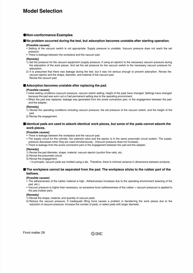
No problem occurred during the test, but adsorption becomes unstable after starting operation.
[Possible causes]• Setting of the vacuum switch is not appropriate. Supply pressure is unstable. Vacuum pressure does not reach the set
pressure.
• There is leakage between the workpiece and the vacuum pad.
[Remedy]1) Set the pressure for the vacuum equipment (supply pressure, if using an ejector) to the necessary vacuum pressure during
the adsorption of the work pieces. And set the set pressure for the vacuum switch to the necessary vacuum pressure for
adsorption.
2) It is presumed that there was leakage during the test, but it was not serious enough to prevent adsorption. Revise the
vacuum ejector and the shape, diameter, and material of the vacuum pad.
Revise the vacuum pad.
Adsorption becomes unstable after replacing the pad.[Possible causes]• Initial setting conditions (vacuum pressure, vacuum switch setting, height of the pad) have changed. Settings have changed
because the pad was worn out or had permanent setting due to the operating environment.
• When the pad was replaced, leakage was generated from the screw connection part, or the engagement between the pad
and the adapter.
[Remedy]1) Revise the operating conditions including vacuum pressure, the set pressure of the vacuum switch, and the height of the
pad.
2) Revise the engagement.
Identical pads are used to adsorb identical work pieces, but some of the pads cannot adsorb the
work pieces.[Possible causes]• There is leakage between the workpiece and the vacuum pad.
• The supply circuit for the cylinder, the solenoid valve and the ejector is in the same pneumatic circuit system. The supply
pressure decreases when they are used simultaneously. (Vacuum pressure does not increase)
• There is leakage from the screw connection part or the engagement between the pad and the adapter.
[Remedy]1) Revise the pad diameter, shape, material, vacuum ejector (suction flow rate), etc.
2) Revise the pneumatic circuit.
3) Revise the engagement.
∗ In principle, vacuum pads are molded using a die. Therefore, there is minimal variance in dimensions between products.
The workpiece cannot be separated from the pad. The workpiece sticks to the rubber part of thebellows.
[Possible causes]• The adhesiveness of the rubber material is high. Adhesiveness increases due to the operating environment (wearing of the
pad, etc.).
• Vacuum pressure is higher than necessary, so excessive force (adhesiveness of the rubber + vacuum pressure) is applied to
the pad (rubber part).
[Remedy]1) Revise the shape, material, and quantity of vacuum pads.
2) Reduce the vacuum pressure. If inadequate lifting force causes a problem in transferring the work pieces due to the
reduction of vacuum pressure, increase the number of pads, or select pads with larger diameter.
Non-conformance Examples
Front matter 29
Model Selection

8/12/2019 Ventosa Especial Da Smc
http://slidepdf.com/reader/full/ventosa-especial-da-smc 30/119
When mounted with the nut, sometimes the buffer operation is not smooth, or the buffer does not slide.
[Possible causes]
• The tightening torque of the nut for mounting the buffer is too high.
• Particles stuck to the sliding surface, or it is scratched.
• Lateral load applied to the piston rod, causing eccentric wearing.
[Remedy]
Tighten the nut to the recommended tightening torque.
The nut may become loose depending on the operating conditions and environment. Be sure to perform regular maintenance.
General Purpose
Product part no.
Product specifications
Pad diameter Mounting thread sizeNut tightening torque
ZP∗ (02 to 08) U, B∗
ZP∗ (10 to 16) UT, CT∗ZP∗ (2004 to 4010) U∗ M8 x 1
M10 x 1
M14 x 1
ø2 to ø16
2004 to 4010
ø10 to ø32
ø20 to ø50
1.5 to 2.0 N·m
2.5 to 3.5 N·m
6.5 to 7.5 N·m
Heavy-duty Pad
Product part no.
Product specifications
Pad diameter Mounting thread size Buffer body materialNut tightening torque
ZP∗ (40/50) H∗ZP∗ (40/50) HB∗
M18 x 1.5
M18 x 1.5
M22 x 1.5
Aluminum alloy
Brass
Steel
Aluminum alloy
BrassSteel
Aluminum alloy
Brass
Steel
9.5 to 10.5 N·m
28 to 32 N·m
48 to 52 N·m
9.5 to 10.5 N·m
28 to 32 N·m48 to 52 N·m
9.5 to 10.5 N·m
45 to 50 N·m
75 to 80 N·m
ø40, ø50
ø63, ø80
ø100, ø125
Heavy-duty Ball Joint Pad
Product part no.
Product specifications
Pad diameter Mounting thread size Buffer body material
Brass
Steel
Brass
Steel
Brass
Steel
Nut tightening torque
ZP2-∗F (40/50) H∗ZP2-∗F (40/50) HB∗
M18 x 1.5
M22 x 1.5
M22 x 1.5
ø40, ø50
ø63, ø80
ø100, ø125
28 to 32 N·m
48 to 52 N·m
45 to 50 N·m
75 to 80 N·m
45 to 50 N·m
75 to 80 N·m
ZP∗ (10 to 32) U, C, B, D∗ZP∗ (10 to 16) F∗
ZP∗ (40, 50) U, C, B, D∗ZP∗ (20 to 50) F∗
ZP∗
(63/80) H∗ZP∗ (63/80) HB∗
ZP∗ (100/125) H∗ZP∗ (100/125) HB∗
∗
∗
∗
∗
∗
∗
ZP2-∗F (63/80) H∗ZP2-∗F (63/80) HB∗
ZP2-∗
F (100/125) H∗ZP2-∗F (100/125) HB∗
JJBJF
J
JBJF
JJBJF
JB
JF
JBJF
JBJF
Time of Replacement of Vacuum Pad
The vacuum pad is disposable. Replace it on a regularbasis.
Continued use of the vacuum pad will cause wear and tear on theadsorption surface, and the exterior dimensions will gradually getsmaller and smaller. As the pad diameter gets smaller, lifting forcewill decrease, though adsorption is possible.It is extremely difficult to provide advice on the frequency ofvacuum pad exchange. This is because there are numerousfactors at work, including surface roughness, operationgenvironment (temperature, humidity, ozone, solvents, etc.), andoperating conditions (vacuum pressure, workpiece weight,
pressing force of the vacuum pad on the workpiece, presence orabsence of a buffer, etc.).Thus, the customer should decide when the vacuum pad shouldbe exchanged, based on its condition at time of initial use.
The bolt may become loose depending on the operatingconditions and environment. Be sure to perform regularmaintenance.
Product specifications
Pad diameter Product part no. Bolt
Bolt tighteningtorque
ø40, ø50
ø63, ø80
ø100, ø125 ZP (100/125) H∗ZP (100/125) HB∗
M3 x 8
M4 x 8
M5 x 10
0.7 to 0.9 N·m
0.9 to 1.1 N·m
2.3 to 2.7 N·m
Assemble parts with recommended tightening torque.
ZP (40/50) H∗ZP (40/50) HB∗
ZP (63/80) H∗ZP (63/80) HB∗
Recommended Tightening Torque for Replacementof Heavy-duty Pad
Front matter 30
Model Selection

8/12/2019 Ventosa Especial Da Smc
http://slidepdf.com/reader/full/ventosa-especial-da-smc 31/119

8/12/2019 Ventosa Especial Da Smc
http://slidepdf.com/reader/full/ventosa-especial-da-smc 32/119
0 . 8
4
1
1 . 5
ø4
ø3
ø2
ø1.4
ø5
ø5.8
6 . 5
0 . 8
2
2
ø7.5
ø6
ø4
ø2
ø6
ø6.7
7
1 . 2
2
2
ø8
ø6
ø4
ø2
ø8
ø8.8
7
1 . 2
2
2
ø8
ø6
ø4
ø2
ø10
ø10.6
2
8 2
2
ø9
ø6
ø4
ø2
ø15
ø15.6
1
R
2 . 5
R
ø1.2ø2
ø3
Note) R part has to be smooth with no corners.
∗ Refer to page 69 for adapter applicable to the ZP2 series.
ø2
2
R
R 4
ø4
ø6
4
0 . 5
1 . 5
1
ø4
ø3
ø2
ø1
ø2
ø2.4
4
0 . 5
1 . 5
1
ø4
ø3
ø2
ø1
ø3.5
ø3.8
4
0 . 8
1 . 5
1
ø4
ø3
ø2
ø1.4
ø4
ø4.8
How to Order
Pad unit
ZP2-B02MU ZP2-B035MU ZP2-B04MU
MU: FlatShort-type Pad
Symbol/Type
ø2, ø3.5, ø4, ø5, ø6, ø8, ø10, ø15
ZP2 B02 MU NPad diameter
B02B035B04B05B06B08B10B15
Pad diameter Blast type
ø2
ø3.5
ø4
ø5
ø6
ø8
ø10
ø15
SymbolPad type
MUType
FlatSymbol
ZP2-B05MU
ZP2-B06MU
ZP2-B10MU ZP2-B15MU
ZP2-B08MU
If an adapter will be made by the customer,design the adapter with the dimensions shown below.
Adapter Mounting Dimensions
Applicable pad
B02MU/B035MU/B04MU/B05MU
Space-saving in the heightdirection
Applicable pad
B06MU/B08MU/B10MU/B15MU
∗ Blast type: Work pieces can be
removed easily.
Pad diameter
Pad material
NSUF
GNGS
Material
NBR
Silicone rubber
Urethane rubber
FKM
Conductive NBR
Conductive silicone rubber
Symbol
Dimensions: Pad Unit
2

8/12/2019 Ventosa Especial Da Smc
http://slidepdf.com/reader/full/ventosa-especial-da-smc 33/119

8/12/2019 Ventosa Especial Da Smc
http://slidepdf.com/reader/full/ventosa-especial-da-smc 34/119
ø8ø8
Width across flat 1.5
(Hexagon)
7
1 . 2
3 . 5
( 1 2 )
M5 x 0.8
1 . 5
ø1.5ø1.5
ø10
ø10.6
Width across flat 1.5
(Hexagon)
2
8
3 . 5
M5 x 0.8
( 1 3 )
1 . 5
ø15
ø15.6
Width across flat 8
(Hexagon)
ø2
ø15
ø15.6
2
8
8
M5 x 0.8
5 . 5
( 1 6 )
Width across flat 8
(Hexagon)
6 . 5
ø2
ø6
ø6.7
0 . 8
8
M5 x 0.8
5 . 5
( 1 4
. 5 )
Width across flat 8
(Hexagon)
7
ø2
ø8
ø8.8
1 . 2
8
M5 x 0.8
5 . 5
( 1 5 )
Width across flat 8
(Hexagon)
ø2
ø10
ø10.6
1 . 2
8
7
M5 x 0.8
5 . 5
( 1 5 )
ZP2-TB06MU-B5 ZP2-TB08MU-B5
ZP2-TB10MU-B5 ZP2-TB15MU-B5
ZP2-TB10MU-H5 ZP2-TB15MU-H5
4
Series ZP2 Short-type Pad
Dimensions: With Adapter

8/12/2019 Ventosa Especial Da Smc
http://slidepdf.com/reader/full/ventosa-especial-da-smc 35/119
4 2
. 5
0 . 5
ø7
ø2.6
ø1.5
ø4
ø4.8
4 2
. 5
0 . 5
ø7
ø2.6
ø1.5
ø6ø6.7
4 2
. 5
0 . 5
ø7
ø2.6
ø1.5
ø8ø9
2 . 5
5
1 . 5
ø7
ø2.6
ø2
ø15
ø15.7
1
2 . 5
ø1.5
ø3
4 5 °
ø4.4
R
R
4 2
. 5
0 . 5
ø7
ø2.6
ø1.2
ø2
ø2.6
Pad unit
ZP2-B02EU
Short-type Padø2, ø4, ø6, ø8, ø15
ZP2 B02 EU NPad diameter
B02B04B060815
Pad diameter Blast type
—
—
ø2
ø4
ø6
ø8
ø15
Symbol
Pad type
ZP2-B04EU
ZP2-B06EU ZP2-08EU
ZP2-15EU
If an adapter will be made by the customer,design the adapter with the dimensions shown below.
Adapter Mounting Dimensions
Note) R part has to be smooth with no corners.∗ Refer to page 70 for adapter applicable to the ZP2 series.
Space-saving in the heightdirection
∗ Blast type: Work pieces can be
removed easily.
Pad diameter
EU: Flat
Symbol/Type
How to Order
EUTypeFlat
Symbol
Pad material
NSUF
GNGS
Material
NBR
Silicone rubber
Urethane rubber
FKM
Conductive NBR
Conductive silicone rubber
Symbol
Dimensions: Pad Unit
5

8/12/2019 Ventosa Especial Da Smc
http://slidepdf.com/reader/full/ventosa-especial-da-smc 36/119
Width across flat 7
(Hexagon)
4
0 . 5
M5 x 0.8
3 . 5
2 . 5
( 1 0 )
ø1.5ø4
ø4.8
Width across flat 7
(Hexagon)
4
0 . 5
M5 x 0.8
2 . 5
3 . 5
( 1 0 )
ø1.2ø2
ø2.6
Width across flat 7
(Hexagon)
4
0 . 5
M5 x 0.8
3 . 5
2 . 5
( 1 0 )
ø1.5
ø6
ø6.7
Width across flat 7
(Hexagon)
4
0 . 5
M5 x 0.8
3 . 5
2 . 5
( 1 0 )
ø1.5
ø8
ø9
Width across flat 7
(Hexagon)
5
1 . 5
M5 x 0.8
2 . 5
3 . 5
( 1 1 )
ø1.5
ø15
ø15.7
How to Order
ZP2-TB02EU-A5
ZP2-TB06EU-A5 ZP2-T08EU-A5
ZP2-T15EU-A5
ZP2-TB04EU-A5
ZP2 B02 EU A5
Pad diameter
B02B04B060815
Pad diameter Blast type
—
—
ø2
ø4
ø6
ø8
ø15
Symbol
Mounting
A5H5
Thread size
M5 x 0.8
M5 x 0.8
Adapter type
Hexagon O.D.
Hexagon socket head
Symbol
NWith adapter
Replacement Part No.Pad unit part no.
ZP2-B02EUZP2-B04EUZP2-B06EUZP2-08EUZP2-15EUZP2-B02EUZP2-B04EUZP2-B06EUZP2-08EUZP2-15EU
Adapter part no.
ZP2A-Z01P
ZP2A-Z02P
ZP2-TB02EU-A5ZP2-TB04EU-A5ZP2-TB06EU-A5ZP2-T08EU-A5ZP2-T15EU-A5ZP2-TB02EU-H5ZP2-TB04EU-H5ZP2-TB06EU-H5ZP2-T08EU-H5ZP2-T15EU-H5
Model
T
Note) in the table indicates the pad material.
∗ Blast type: Work pieces can be
removed easily.
Vacuum inlet direction
TDirection
Vertical
Symbol
Pad type
EUType
FlatSymbol
Pad material
NSUF
GNGS
Material
NBR
Silicone rubber
Urethane rubber
FKM
Conductive NBR
Conductive silicone rubber
Symbol
Dimensions: With Adapter
6
Series ZP2 Short-type Pad

8/12/2019 Ventosa Especial Da Smc
http://slidepdf.com/reader/full/ventosa-especial-da-smc 37/119
Width across flat 1.5
(Hexagon) 4
0 .
5
( 9 )
1 .
5
3 . 5
M5 x 0.8
ø1.5
ø6
ø6.7
Width across flat 1.5
(Hexagon) 4
0 .
5
1 .
5
3 .
5
( 9 )
M5 x 0.8
ø1.5
ø8
ø9
Width across flat 1.5
(Hexagon)
5
1 .
5
3 .
5
M5 x 0.8
ø1.5
1 .
5
( 1 0 )
ø15
ø15.7
Width across flat 1.5
(Hexagon) 4
0 .
5
M5 x 0.8
3 . 5
1 .
5
( 9 )
ø1.5
ø4
ø4.8
4
0 . 5
3 .
5
( 9 )
1 .
5
M5 x 0.8
ø1.2
ø2
ø2.6
Width across flat 1.5
(Hexagon)
ø7 ø7
ø7ø7
ø7
ZP2-TB06EU-H5 ZP2-T08EU-H5
ZP2-T15EU-H5
ZP2-TB02EU-H5 ZP2-TB04EU-H5
Dimensions: With Adapter
7
Series ZP2

8/12/2019 Ventosa Especial Da Smc
http://slidepdf.com/reader/full/ventosa-especial-da-smc 38/119
5
3
1 . 2
ø6
ø2.7
ø8.3
ø2.2
ø8
2 . 5
4
ø4
ø2
ø1.2
ø4
ø4.5
0 . 5
ø6
ø2.7
ø2.2
ø6
ø6.3
5
3
1 . 1
4 2
. 5
0 . 5
ø4
ø2
ø1.2
ø2
ø2.5
2 . 5
4
ø4
ø2
ø1.2
ø3
ø3.5
0 . 5
How to Order
Short-type Padø2, ø3, ø4, ø6, ø8
ZP2 02 AU N
Pad diameter
02030406
B08
Pad diameter Blast type
—
—
—
—
ø2
ø3
ø4
ø6
ø8
Symbol
Pad type
ZP2-02AU ZP2-03AU ZP2-04AU
ZP2-06AU ZP2-B08AU
Space-saving in the heightdirection
∗ Blast type: Work pieces can be
removed easily.
AU: Flat
Symbol/Type
Pad diameter
Pad unit
AUType
FlatSymbol
Pad material
NSUF
GNGS
Material
NBR
Silicone rubber
Urethane rubber
FKM
Conductive NBR
Conductive silicone rubber
Symbol
Dimensions: Pad Unit
8

8/12/2019 Ventosa Especial Da Smc
http://slidepdf.com/reader/full/ventosa-especial-da-smc 39/119
3 . 5
ø4
ø1.6 ø2
ø4
ø2ø2
ø1.1ø0.8
8
3 . 5
8 3
ø1.1
ø2.2
R
R
8
3
3 . 5
( 1 4
. 5 )
M5 x 0.8Width across flat 7
(Hexagon)
ø1.1ø0.8
ø2ø1.6
8
3 . 5
3
( 1 4
. 5 )
M5 x 0.8Width across flat 7
(Hexagon)
How to Order
Pad unit
Nozzle Padø0.8, ø1.1
ZP2-08AN ZP2-11AN
ZP2 08 AN NPad diameter
0811
Pad diameter
ø0.8
ø1.1
Symbol
Pad type
ANType
NozzleSymbol
If an adapter will be made by the customer,design the adapter with the dimensions shown below.
Adapter Mounting Dimensions
With adapter
ZP2-T08AN-A5 ZP2-T11AN-A5
ZP2 08 AN A5
Pad diameter
0811
Pad diameter
ø0.8
ø1.1
Symbol
Mounting
A5Thread size
M5 x 0.8
Symbol
N
Replacement Part No.Pad unit part no.
ZP2-08ANZP2-11AN
Adapter part no.
ZP2A-Z21PZP2-T08AN-A5ZP2-T11AN-A5
Model
T
For adsorption of small
components (such as IC chips)
Note) R part has to be smooth with no corners.∗ Refer to page 70 for adapter applicable to the ZP2 series.
Note) in the table indicates the pad material.
AN: Nozzle
Symbol/Type
Pad diameter
Pad material
NSUF
GNGS
Material
NBR
Silicone rubber
Urethane rubber
FKM
Conductive NBR
Conductive silicone rubber
Symbol
Dimensions: Pad Unit
How to Order
Vacuum entry direction
TDirection
Vertical
Symbol
Pad type
ANType
Nozzle
Symbol
Pad material
NSUF
GNGS
Material
NBR
Silicone rubber
Urethane rubber
FKM
Conductive NBR
Conductive silicone rubber
Symbol
Dimensions: With Adapter
9

8/12/2019 Ventosa Especial Da Smc
http://slidepdf.com/reader/full/ventosa-especial-da-smc 40/119

8/12/2019 Ventosa Especial Da Smc
http://slidepdf.com/reader/full/ventosa-especial-da-smc 41/119

8/12/2019 Ventosa Especial Da Smc
http://slidepdf.com/reader/full/ventosa-especial-da-smc 42/119

8/12/2019 Ventosa Especial Da Smc
http://slidepdf.com/reader/full/ventosa-especial-da-smc 43/119
1 5
. 5
6 . 5
ø7
ø11
ø12
ø10
ø6.8
ø2.5
2 4
1 5
ø13
ø15ø14
ø3
1 5
. 5
6 . 5
ø7
ø16
ø17
ø15ø11.8
ø2.5
2 4
1 5
ø13
ø18
ø17.5
ø16ø7.2
ø4
4 2
. 5
3 2
. 5
ø15
ø26
ø25
ø10.2
ø4
3 8
4 9
ø15
ø33
ø30
ø13.8
ø4
ø27
1 5
. 5
ø7
ø2.8
ø6
ø7
ø8
6 . 5
1 8
7 . 7
ø13
ø3
ø9
ø10
If an adapter will be made by the customer,
design the adapter with the dimensions shown below.
Adapter Mounting Dimensions
Applicable pad
09J/14J/16J
Applicable pad
06J/B10J/B15J
Applicable pad
B25J/B30J
Note) R part has to be smooth with no corners.∗ Refer to page 66 for adapter applicable to
the ZP series.
R
ø2.5
ø3.8
ø4.9
2
0 . 5
6 7
R
2 5 °
2 5 °
ø4.9
R
ø2.5
ø4.5ø5
ø6.6
1
R R
R
7 8
R
R
R R
R
R
R
ø3.5
ø5ø6
ø7.9
2
8 9
Lock ring
Lock ring Lock ring
Lock ring
Lock ring
ø32
3 0 °
4 5 °
4 5 °
3 0 °
How to Order
Pad unit
Bellows Padø6, ø9, ø10, ø14, ø15, ø16, ø25, ø30
Pad type
JType
Bellows (Multistage type)Symbol
With/Withoutlock ring
X19With lock ring
Without lock ring Note)
Nill
ZP2-06J
ZP2 X1906 J NPad diameter
0609
B1014
B1516
B25B30
Pad diameter Blast type
—
—
—
—
ø6
ø9
ø10
ø14
ø15
ø16
ø25
ø30
Symbol
ZP2-B10J
ZP2-14J ZP2-B15J ZP2-16J
ZP2-B25J ZP2-B30J
For use where there is nospace for the buffer (springtype)
Work pieces withinclined adsorptionsurface
Applicable for theZP series adapter
ZP2-09J
∗ Blast type: Work pieces can be
removed easily.Note) ø6, ø10, ø15 are
not available.
J: Bellows(Multistage type)
Symbol/Type
Pad diameter
Pad material
NSUF
GNGS
Material
NBR
Silicone rubber
Urethane rubber
FKM
Conductive NBR
Conductive silicone rubber
Symbol
Dimensions: Pad Unit
13

8/12/2019 Ventosa Especial Da Smc
http://slidepdf.com/reader/full/ventosa-especial-da-smc 44/119
ø12
ø20
ø21
ø18 1 3
5 . 5
3 . 5
ø4.6
ø10.8
ø15
9
4
2
ø4
ø6
ø8
ø2.5
ø3.3
ø6
ø7
ø8.4
2
9
ø4
ø6
ø8
4
ø2.5
ø9.6
ø4.7
ø8
ø9
2
2
9 . 5
ø6.8
ø10
ø10.8
ø11
3
3 . 5
ø4.6
ø7.8
ø11
ø9.4
ø15
ø16
ø14.4 1 1
4 . 5
3 . 5
ø11
ø4.6
ø7.8
6
2 . 5
1 . 5
1
ø4.5
ø3
ø2
ø1.4
ø1.5
ø4.6
ø4.1
ø4.8
1
ø1.2
ø2
ø3
R 2
. 5 R
ø4
ø6
2R
R 4
ø1.5Width across flat 3(Hexagon)
M5 x 0.8
ø7.8
2
4
7
ø2.5
Width across flat 3(Hexagon)
M5 x 0.8
2
9 . 5
5 . 5
ø10.8
ø2.5
Pad material
NSUF
GNGS
Material
NBR
Silicone rubber
Urethane rubber
FKM
Conductive NBR
Conductive silicone rubber
Symbol
How to Order
Pad unit
ø4, ø6, ø8, ø10, ø15, ø20
ZP2-B04MB
B04 MB NZP2
Pad type
MBType
Bellows
Symbol
Pad diameter
B04B06B08B10B15B20
Pad diameter Blast type
ø4
ø6
ø8
ø10
ø15
ø20
Symbol
ZP2-B06MB ZP2-B08MB
ZP2-B10MB ZP2-B15MB ZP2-B20MB
For use where there is nospace for the buffer (springtype)
Work pieces with inclinedadsorption surface
Applicable pad
B04MBApplicable pad
B06MB/B08MBApplicable pad
B10MB/B15MBApplicable pad
B20MB
If an adapter will be made by the customer, design the adapter with the dimensions shown below.
Adapter Mounting Dimensions
Note) R part has to be smooth with no corners.
∗ Refer to pages 69 and 70 for adapter applicable to the ZP2 series.
∗ Blast type: Work pieces can be removed easily.
Bellows PadMB: Bellows
Symbol/Type
Pad diameter
Dimensions: Pad Unit
14

8/12/2019 Ventosa Especial Da Smc
http://slidepdf.com/reader/full/ventosa-especial-da-smc 45/119
Width across flat
1.5 (Hexagon)
4
ø1.5
ø4.7
ø8
ø9
M5 x 0.8
ø8
( 1 4 )
1 . 5
9
3 .
5
Width acrossflat 3
(Hexagon)
9 . 5
ø2.5
ø10
ø11
3
3 .
5
( 1 3 )
M5 x 0.8
ø11
Width acrossflat 3
(Hexagon)
ø2.5
ø14.4
ø15
ø16
1 1
4 .
5
M5 x 0.8
ø11
3 .
5
( 1 4 .
5 )
Width acrossflat 3
(Hexagon)
ø2.5
ø20
ø18
ø21
1 3
5 .
5
( 1 9 )
6
M5 x 0.8
ø15
Width acrossflat 8
(Hexagon)
9
4
ø2
ø3.3ø6
ø7
8
( 1 7 )
M5 x 0.8
5 .
5
Width acrossflat 8
(Hexagon)
9
4
ø2
ø4.7
ø9.6
ø8
ø9
( 1 7 )
8 5
. 5
M5 x 0.8
Width across flat 5
(Hexagon)
6
2 . 5
M3 x 0.5
( 1 1 ) 2
. 5
2 . 5
ø1.2
ø4.1
ø4.6
ø4.8
Width across flat
1.5 (Hexagon) 9
4
ø3.3
ø1.5
ø6
ø7
M5 x 0.8
ø8 3 .
5
1 .
5
( 1 4 )
ø8.4 ø9.6 ø10.8
ø8.4
ZP2-TB04MB-A3 ZP2-TB06MB-H5 ZP2-TB08MB-H5 ZP2-TB10MB-H5
ZP2-TB15MB-H5 ZP2-TB20MB-H5 ZP2-TB06MB-B5 ZP2-TB08MB-B5
B04 MB A3
Mounting
NZP2With adapter
Replacement Part No.Pad unit part no.
ZP2-B04MB
ZP2-B06MB
ZP2-B08MB
ZP2-B10MB
ZP2-B15MB
ZP2-B20MB
ZP2-B06MB
ZP2-B08MB
Adapter part no.
ZP2A-M01P
ZP2A-M02P
ZP2A-M05
ZP2A-M06
ZP2A-M04
ZP2-TB04MB-A3ZP2-TB06MB-H5ZP2-TB08MB-H5ZP2-TB10MB-H5ZP2-TB15MB-H5ZP2-TB20MB-H5ZP2-TB06MB-B5ZP2-TB08MB-B5
Model
Pad type
Pad diameter
B04B06B08B10B15B20
Pad diameter Blast type
ø4
ø6
ø8
ø10
ø15
ø20
Symbol
T
A3 (M3 x 0.5 Male thread)
H5 (M5 x 0.8 Male thread)
B5 (M5 x 0.8 Female thread)
B04
—
—
Pad diameter(Symbol)Thread size (Symbol)
B06
—
B08
—
B10
—
—
B15
—
—
B20
—
—
Note) in the table indicates the pad material.
∗ Blast type: Work pieces can be
removed easily.
Vacuum inlet direction
TDirectionVertical
Symbol
How to Order
MB TypeBellowsSymbol
Dimensions: With Adapter
15
Series ZP2
Pad material
NSUF
GNGS
Material
NBR
Silicone rubber
Urethane rubber
FKM
Conductive NBR
Conductive silicone rubber
Symbol

8/12/2019 Ventosa Especial Da Smc
http://slidepdf.com/reader/full/ventosa-especial-da-smc 46/119
6 .
4
1
4 .
5
ø6.4
ø4.3
ø2
ø2.6
ø5
ø5.7
ø6.4
8
4 .
7
ø4
ø2.2
ø1.5
ø4
ø4.3
8
5 . 7
1
ø8
ø6.2
ø4
ø3.3
ø6
ø6.7
ø8
4 4
4 0 .
2
ø30
ø27
ø35
ø46
ø50
4 4
4 0 .
2
ø24
ø21
ø29
ø40
ø44
4 .
6
2 .
3
2
ø3.8
ø2.5
ø1
ø2
ø2.5
ø3.8
How to Order
Pad unit
ø2, ø4, ø5, ø6, ø40, ø46
ZP2-02ZJ
ZP2 02 ZJ NPad diameter
020405064046
Pad diameter
ø2
ø4
ø5
ø6
ø40
ø46
Symbol
Pad type
ZP2-04ZJ ZP2-05ZJ ZP2-06ZJ
ZP2-40ZJ ZP2-46ZJ
For use where there is nospace for the buffer (springtype)
Work pieces with inclinedadsorption surface
Bellows PadZJ: Bellows
Symbol/Type
Pad diameter
Pad material
NSUF
GNGS
Material
NBR
Silicone rubber
Urethane rubber
FKM
Conductive NBR
Conductive silicone rubber
Symbol
ZJType
Bellows
Symbol
Dimensions: Pad Unit
16

8/12/2019 Ventosa Especial Da Smc
http://slidepdf.com/reader/full/ventosa-especial-da-smc 47/119
7 7
8
Y
20
21
a A
C
8
Y
30
31
C
a A
AA
A-A
4
ø3
ø 8 .8 ( 5 )
5
ø12.8 0
. 8
1 5
°
2
AA
A-A
4
ø3
( 5 )
ø 14 .8
5
ø20.4
1 5 °
0 . 8
2
3 0 °
A-A
3
. 5
( 5 )
ø3
ø 6
5 0
. 8
ø8.4
1 . 5
8
7
Y
a A
C
b
B
12 20 30
AA
How to Order
Pad unit
Oval Pad
3507 W NPad size
602080204030503060308030
Size
6 x 20
8 x 20
4 x 30
5 x 30
6 x 30
8 x 30
Symbol
350740105010601040205020
Size
3.5 x 7
4 x 10
5 x 10
6 x 10
4 x 20
5 x 20
Symbol
ZP2
For work pieces with limit-ations on the adsorptionsurface
Note) R part has to be smooth with no corners.∗ Refer to page 69 for adapter applicable to the ZP2 series.
If an adapter will be made by the customer, design the adapter with the dimensions shown below.
Adapter Mounting Dimensions
Applicable pad
4020W/5020W/6020W/8020WApplicable pad
3507W/4010W/5010W/6010WApplicable pad
4030W/5030W/6030W/8030W
Dimensions
a3.5
4
5
6
A4.5
5
6
7
b 7
10
B 8
11
C
2 x 1.5
2.5
Y
0.5
ZP2-3507WZP2-4010WZP2-5010W
ZP2-6010W
Model
Dimensions
a4
5
6
8
A5
6
7
9
C2 x 1.8
2 x 2
2.5
3
Y
0.5
0.8
ZP2-4020WZP2-5020WZP2-6020W
ZP2-8020W
Model
Dimensions
a4
5
6
8
A5
6
7
9
C2 x 1.8
2 x 2.5
Y
0.5
0.8
ZP2-4030WZP2-5030WZP2-6030W
ZP2-8030W
Model
ZP2- W ZP2- 20 W ZP2- 30 W
W: Oval
Symbol/Type
Pad size 3.5 x 7 to 8 x 30
Pad material
NSUF
GNGS
Material
NBR
Silicone rubber
Urethane rubber
FKM
Conductive NBR
Conductive silicone rubber
Symbol
Pad type
WType
OvalSymbol
Dimensions: Pad Unit
17

8/12/2019 Ventosa Especial Da Smc
http://slidepdf.com/reader/full/ventosa-especial-da-smc 48/119
bB
C
8
Y
a A
( 1 4 )
6
M5 x 0.8
4
7
a A
21
7
C
8
Y
M5 x 0.8
6
( 1 4 )
4
20
30
31
a A
7
C
8
Y
M5 x 0.8
6
( 1 4 )
4
ø8
12
ø19
30
ø11
20
ZP2 T B53507 W N
Pad size
Pad type
Vacuum inletSymbol Thread size
B5 M5 x 0.8
Pad unit part no.
ZP2-3507WZP2-4010WZP2-5010WZP2-6010WZP2-4020WZP2-5020WZP2-6020WZP2-8020WZP2-4030WZP2-5030WZP2-6030WZP2-8030W
Adapter part no.
ZP2A-001
ZP2A-002
ZP2A-003
ZP2-T3507W-B5ZP2-T4010W-B5ZP2-T5010W-B5ZP2-T6010W-B5ZP2-T4020W-B5ZP2-T5020W-B5ZP2-T6020W-B5ZP2-T8020W-B5ZP2-T4030W-B5ZP2-T5030W-B5ZP2-T6030W-B5ZP2-T8030W-B5
Model
Replacement Part No.
With adapter
Dimensions
a3.5
4
5
6
A4.5
5
6
7
b 7
10
B 8
11
C
2 x 1.5
2.5
Y
0.5
ZP2-T3507W-B5ZP2-T4010W-B5ZP2-T5010W-B5ZP2-T6010W-B5
Model
Dimensions
a4
5
6
8
A5
6
7
9
C2 x 1.8
2 x 2
2.5
3
Y
0.5
0.8
ZP2-T4020W-B5ZP2-T5020W-B5ZP2-T6020W-B5ZP2-T8020W-B5
Model
Dimensions
a4
5
6
8
A5
6
7
9
C2 x 1.8
2 x 2.5
Y
0.5
0.8
ZP2-T4030W-B5ZP2-T5030W-B5ZP2-T6030W-B5ZP2-T8030W-B5
Model
602080204030503060308030
Size
6 x 20
8 x 20
4 x 30
5 x 30
6 x 30
8 x 30
Symbol
350740105010601040205020
Size
3.5 x 7
4 x 10
5 x 10
6 x 10
4 x 20
5 x 20
Symbol
Note) in the table indicates the pad material.
How to Order
Vacuum inlet direction
TDirection
Vertical
Symbol
Pad material
NSUF
GNGS
Material
NBR
Silicone rubber
Urethane rubber
FKM
Conductive NBR
Conductive silicone rubber
Symbol
WType
OvalSymbol
Dimensions: With Adapter
ZP2-T W-B5
ZP2-T 30
W-B5
ZP2-T 20 W-B5
18
Series ZP2 Oval Pad: With Adapter (Vacuum Inlet Direction: Vertical)

8/12/2019 Ventosa Especial Da Smc
http://slidepdf.com/reader/full/ventosa-especial-da-smc 49/119
Width across flat 8
(Hexagon)M5 x 0.8
M5 x 0.8
Width across flat 14
(Hexagon)
8
Y
6
30
31
a A
C
M10 x 1
5
D
E
1 3
3
3 ( F )
Width across flat 8
(Hexagon)M5 x 0.8
Width across flat 14
(Hexagon)
M5 x 0.8
8
Y
6
b
B
a A C
D
E
1 3
3
3
5
M10 x 1 ( F )
Width across flat 8
(Hexagon)M5 x 0.8
M5 x 0.8
Width across flat 14
(Hexagon)
8
Y
6
a A
20
21
C
5
M10 x 1
D
E
1 3
3
3 ( F )
ZP2 T K3507 W N 10 B5
Pad size
602080204030503060308030
Size
6 x 20
8 x 20
4 x 30
5 x 30
6 x 30
8 x 30
Symbol
350740105010601040205020
Size
3.5 x 7
4 x 10
5 x 10
6 x 10
4 x 20
5 x 20
SymbolPad material ()
NSUF
GNGS
Material
NBR
Silicone rubber
Urethane rubber
FKM
Conductive NBR
Conductive silicone rubber
Symbol
Pad typeSymbol
WType
OvalBuffer specification
Symbol Specification
K Non-rotating
Buffer stroke ( )Symbol Stroke
1020304050
10 mm
20 mm
30 mm
40 mm
50 mm
Vacuum inlet ()
Symbol Applicable tube O.D.B50406
M5 x 0.8ø4 one-touch fitting
ø6 one-touch fitting
With buffer
Dimensions: With Buffer
Dimensionsa
3.5
4
5
6
A4.5
5
6
7
b 7
10
B 8
11
C
2 x 1.5
2.5
Y
0.5
ZP2-T3507WK -B5ZP2-T4010WK -B5ZP2-T5010WK -B5ZP2-T6010WK -B5
Model
Dimensionsa4
5
6
8
A5
6
7
9
C2 x 1.8
2 x 2
2.5
3
Y
0.5
0.8
ZP2-T4020WK -B5ZP2-T5020WK -B5ZP2-T6020WK -B5ZP2-T8020WK -B5
Model
Dimensionsa4
5
6
8
A5
6
7
9
C2 x 1.8
2 x 2.5
Y
0.5
0.8
ZP2-T4030WK -B5ZP2-T5030WK -B5ZP2-T6030WK -B5ZP2-T8030WK -B5
Model
Dimensions common for allthree drawingsDimensions (per buffer stroke)
D11.5
21.5
31.5
41.5
51.5
E23
51
77
F 61.5
99.5
109.5
145.5
155.5
1020304050
Stroke ( )
Buffer strokeSymbol Stroke
10
20304050
10 mm
20 mm30 mm
40 mm
50 mm
Vacuum inlet
SymbolApplicable
tube O.D.
B5
04
06
M5 x 0.8
ø6 one-touch fitting
ø4 one-touch fitting
Replacement Part No.Pad unit part no.
ZP2-3507W
ZP2-4010W
ZP2-5010W
ZP2-6010W
ZP2-4020W
ZP2-5020W
ZP2-6020W
ZP2-8020WZP2-4030W
ZP2-5030W
ZP2-6030W
ZP2-8030W
Adapter part no.
ZP2A-001
ZP2A-002
Buffer assembly part no.
ZPB2K -
ZP2A-003
ZP2-T3507WK -ZP2-T4010WK -ZP2-T5010WK -ZP2-T6010WK -ZP2-T4020WK -ZP2-T5020WK -ZP2-T6020WK -
ZP2-T8020WK -ZP2-T4030WK -ZP2-T5030WK -ZP2-T6030WK -ZP2-T8030WK -
Model
Note 1) in the table indicates the pad material.
Note 2) in the table indicates the buffer stroke.
Note 3) in the table indicates the vacuum inlet.
Buffer Specifications
At 0 stroke
At Full stroke
Stroke (mm)
Tightening torque
10, 20, 30, 40, 50
1.0 N
3.0 N
3.0 N·m ±5%
Spring reactiveforce
How to Order
Vacuum inlet direction
T DirectionVerticalSymbol
ZP2-T WK -B5
ZP2-T 30 WK -B5
ZP2-T 20 WK -B5
19
Series ZP2

8/12/2019 Ventosa Especial Da Smc
http://slidepdf.com/reader/full/ventosa-especial-da-smc 50/119
øH
M5 x 0.8
Width across flat 14
(Hexagon)
Width across flat 8
(Hexagon)
Width across flat J(Hexagon)
M5 x 0.8
8
Y
6
M10 x 1
30
31
a A
C
D
3
3
E
1 3
( G )
( F )
øH
M5 x 0.8
M5 x 0.8
Width across flat 14
(Hexagon)
Width across flat 8
(Hexagon)
Width across flat J(Hexagon)
8
Y
6
( G )
M10 x 1
D
3
3
E
1 3
b
B
a A C
( F )
øH
Width across flat 8
(Hexagon)
Width across flat J(Hexagon)
M5 x 0.8
Width across flat 14
(Hexagon)
M5 x 0.8 ( G )
M10 x 1
a A
20
21
C
D
3
3
E
1 3
8
Y
6
( F )
0406
Dimensions
a4
5
6
8
A5
6
7
9
C2 x 1.8
2 x 2
2.5
3
Y
0.5
0.8
ZP2-T4020WK -ZP2-T5020WK -ZP2-T6020WK -ZP2-T8020WK -
Model0406040604060406
Dimensions
a3.5
4
5
6
A4.5
5
6
7
b 7
10
B 8
11
C
2 x 1.5
2.5
Y
0.5
ZP2-T3507WK -ZP2-T4010WK -ZP2-T5010WK -ZP2-T6010WK -
Model0406040604060406
0406
Dimensionsa4
5
6
8
A5
6
7
9
C2 x 1.8
2 x 2.5
Y
0.5
0.8
ZP2-T4030WK -ZP2-T5030WK -ZP2-T6030WK -ZP2-T8030WK -
Model
040604060406
Dimensions common for all three drawingsDimensions (per buffer stroke)
D
11.521.5
31.5
41.5
51.5
E
23
51
77
F
61.5 99.5
109.5
145.5
155.5
G
13.9
J
8
GH: ø4 H: ø6
14.7
J
10
1020304050
Stroke ( )
ZP2-T WK -
0406ZP2-T 30 WK -
0406ZP2-T 20 WK -
20
Series ZP2 Oval Pad: With Buffer (Vacuum Inlet Direction: Vertical)
Dimensions: With Buffer

8/12/2019 Ventosa Especial Da Smc
http://slidepdf.com/reader/full/ventosa-especial-da-smc 51/119
P
M5 x 0.8
Width across flat 8
(Hexagon)Width across flat 10
(Hexagon)
8
Y
6R
30
31
a AC
4
4
2 1
Q
ø S
M5 x 0.8
( 6 0 )
3 1
1 4
. 9
P
Width across flat 8
(Hexagon)
M5 x 0.8
Width across flat 10
(Hexagon)
8
Y
6
4
4
2 1
ø S
M5 x 0.8
R
Q
b
B
C a A
1 4
. 9
( 6 0 )
3 1
P
M5 x 0.8
Width across flat 10
(Hexagon)
Width across flat 8
(Hexagon)
Y
6R
a A
20
21
C
4
4
2 1
Q
ø S
M5 x 0.8
( 6 0 )
3 1
8
1 4
. 9
How to Order
ZP2 R 3507 W N 04 A5
Pad size
350740105010601040205020602080204030503060308030
Size
3.5 x 7
4 x 10
5 x 10
6 x 10
4 x 20
5 x 20
6 x 20
8 x 20
4 x 30
5 x 30
6 x 30
8 x 30
Symbol
Pad material ()
NSUF
GNGS
Material
NBR
Silicone rubber
Urethane rubber
FKM
Conductive NBR
Conductive silicone rubber
Symbol
Pad typeSymbol
WType
Oval
Vacuum inlet ()
0406
ø4
ø6
Applicable tube O.D.Symbol
Mounting
Symbol Thread sizeA5B5
M5 x 0.8 (Male thread)M5 x 0.8 (Female thread)
Without buffer
0406
Dimensionsa
3.5
4
5
6
A4.5
5
6
7
b 7
10
B 8
11
C
2 x 1.5
2.5
Y
0.5
ZP2-R3507W--A5ZP2-R4010W--A5ZP2-R5010W--A5ZP2-R6010W--A5
Model
Dimensionsa4
5
6
8
A5
6
7
9
C2 x 1.82 x 2
2.5
3
Y
0.5
0.8
ZP2-R4020W--A5ZP2-R5020W--A5ZP2-R6020W--A5ZP2-R8020W--A5
Model
Dimensionsa4
5
6
8
A4.8
6
7
9
C2 x 1.8
2 x 2.5
Y
0.5
0.8
ZP2-R4030W--A5ZP2-R5030W--A5ZP2-R6030W--A5ZP2-R8030W--A5
Model
Dimensions common for all
three drawingsDimensions (per applicable tube)P4
6
Q20.6
21.6
R15.6
16.6
S10.4
12.8ø4ø6
Applicable tube O.D. ()
Replacement Part No.Pad unit part no.
ZP2-3507WZP2-4010WZP2-5010WZP2-6010WZP2-4020W
ZP2-5020WZP2-6020WZP2-8020WZP2-4030WZP2-5030WZP2-6030WZP2-8030W
Adapter part no.
ZP2A-001
ZP2A-002
Type R adapter part no.
ZPRS--A5
ZPRS--B5
ZP2A-003
ZP2-R3507W--A5ZP2-R4010W--A5ZP2-R5010W--A5ZP2-R6010W--A5ZP2-R4020W--A5
ZP2-R5020W--A5ZP2-R6020W--A5ZP2-R8020W--A5ZP2-R4030W--A5ZP2-R5030W--A5ZP2-R6030W--A5ZP2-R8030W--A5
Model
ZP2-R3507W--B5ZP2-R4010W--B5ZP2-R5010W--B5ZP2-R6010W--B5ZP2-R4020W--B5
ZP2-R5020W--B5ZP2-R6020W--B5ZP2-R8020W--B5ZP2-R4030W--B5ZP2-R5030W--B5ZP2-R6030W--B5ZP2-R8030W--B5
Note 1) in the table indicates the pad material.Note 2) in the table indicates the vacuum inlet.
Vacuum inlet
0406
ø4
ø6
Symbol Applicable tube O.D.
Female thread mounting
Male thread mounting
Vacuum inlet direction
RDirection
Lateral
Symbol
Dimensions: Without Buffer
ZP2-R W- -A5 0406ZP2-R 20 W- -A5 04
06ZP2-R 30 W- -A5
21
Series ZP2

8/12/2019 Ventosa Especial Da Smc
http://slidepdf.com/reader/full/ventosa-especial-da-smc 52/119
Width across flat 10(Hexagon)
P
M5 x 0.8
M5 x 0.8
bB
C
ø S
5
Q
a A
8
Y
6 1 4
. 9
3 1
( 3 9 )
R
P
M5 x 0.8Width across flat 10(Hexagon)
M5 x 0.8
a A
2021
C
ø S
R
5
Q
Y
6
( 3 9 )
8
3 1
1 4
. 9
P
M5 x 0.8
M5 x 0.8
Width across flat 10
(Hexagon)
ø S
30
31
a A C
5
Q
Y
( 3 9 )
8
3 1
1 4
. 9
6R
0406ZP2-R W- -B5
0406ZP2-R 30 W- -B5
0406ZP2-R 20 W- -B5
Dimensions
a3.5
4
5
6
A4.5
5
6
7
b 7
10
B 8
11
C
2 x 1.5
2.5
Y
0.5
ZP2-R3507W--B5ZP2-R4010W--B5ZP2-R5010W--B5ZP2-R6010W--B5
Model
Dimensions
a4
5
6
8
A5
6
7
9
C2 x 1.8
2 x 2
2.5
3
Y
0.5
0.8
ZP2-R4020W--B5ZP2-R5020W--B5ZP2-R6020W--B5ZP2-R8020W--B5
Model
Dimensions
a4
5
6
8
A5
6
7
9
C2 x 1.8
2 x 2.5
Y
0.5
0.8
ZP2-R4030W--B5ZP2-R5030W--B5ZP2-R6030W--B5ZP2-R8030W--B5
Model
Dimensions common for all three drawings
Dimensions (per applicable tube)
P46
Q20.6
21.6
R15.6
16.6
S10.4
12.8
ø4ø6
Applicable tube O.D. ()
Dimensions: Without Buffer
22
Series ZP2 Oval Pad: Without Buffer (Vacuum Inlet Direction: Lateral)

8/12/2019 Ventosa Especial Da Smc
http://slidepdf.com/reader/full/ventosa-especial-da-smc 53/119
P
M5 x 0.8
Width across flat 6
(Hexagon)Width across flat 14
(Hexagon)
Width across flat 10
(Hexagon)
ø S
Q
Y
8
3 1
1 4 . 9
6R
D
E
1 1
3
3 M10 x 1
( F )
P
M5 x 0.8
Width across flat 6
(Hexagon)Width across flat 14(Hexagon)
Width across flat 10
(Hexagon)
ø S
Q
8
Y
6 1 4 . 9
3 1
R
D
3
3 M10 x 1
E
1 1
b
B
C a A
( F )
P
M5 x 0.8
Width across flat 10
(Hexagon)
Width across flat 14(Hexagon)
Width across flat 6
(Hexagon)
ø S
R
Q
Y
6
8
3 1
1 4 . 9
D
3
3 M10 x 1
E
1 1
a A
20
21
C
( F )
30
31
a AC
How to Order
ZP2 R K3507 W N 10 04
Pad size
Pad material ()
NSUF
GNGS
Material
NBR
Silicone rubber
Urethane rubber
FKM
Conductive NBRConductive silicone rubber
Symbol
Pad typeBuffer specification
Buffer stroke ( )
1020304050
10 mm
20 mm
30 mm
40 mm
50 mm
Symbol Stroke
Vacuum inlet ()
0406
ø4
ø6
Symbol Applicable tube O.D.With buffer
0406
Dimensions common for all three drawings
D31
41
51
E51
77
F 132
168
178
304050
Stroke ( )
Dimensions (per stroke)D11
21
E23
51
F 84
1221020
Stroke ( )
Dimensions (per applicable tube)P4
6
Q20.6
21.6
R15.6
16.6
S10.4
12.8ø4ø6
Applicable tube O.D. ()
602080204030503060308030
Size
6 x 20
8 x 20
4 x 30
5 x 30
6 x 30
8 x 30
Symbol
350740105010601040205020
Size
3.5 x 7
4 x 10
5 x 10
6 x 10
4 x 20
5 x 20
Symbol
Replacement Part No.Pad unit part no.
ZP2-3507W
ZP2-4010W
ZP2-5010W
ZP2-6010W
ZP2-4020W
ZP2-5020W
ZP2-6020W
ZP2-8020W
ZP2-4030W
ZP2-5030WZP2-6030W
ZP2-8030W
Adapter part no.
ZP2A-001
ZP2A-002
Type R adapter part no.
ZPRS--B5
ZP2A-003
ZP2-R3507WK -ZP2-R4010WK -ZP2-R5010WK -ZP2-R6010WK -ZP2-R4020WK -ZP2-R5020WK -ZP2-R6020WK -ZP2-R8020WK -ZP2-R4030WK -ZP2-R5030WK -ZP2-R6030WK -ZP2-R8030WK -
Model Buffer assembly part no.
ZPB2K
Buffer stroke
1020
304050
10 mm
20 mm
30 mm40 mm
50 mm
Symbol Stroke
Vacuum inlet
04
06
ø4
ø6
SymbolApplicable
tube O.D.
Dimensionsa
3.5456
A4.5567
b 7
10
B 8
11
C
2 x 1.5
2.5
Y
0.5
ZP2-R3507WK -ZP2-R4010WK -ZP2-R5010WK -ZP2-R6010WK -
Model
Dimensionsa4
5
6
8
A5
6
7
9
C2 x 1.8
2 x 2
2.5
3
Y
0.5
0.8
ZP2-R4020WK -ZP2-R5020WK -ZP2-R6020WK -ZP2-R8020WK -
Model
Dimensionsa4
5
6
8
A5
6
7
9
C2 x 1.8
2 x 2.5
Y
0.5
0.8
ZP2-R4030WK -ZP2-R5030WK -ZP2-R6030WK -ZP2-R8030WK -
Model
Buffer Specifications (Non-rotating)
At 0 stroke
At Full stroke
Stroke (mm)
Tightening torque
10, 20, 30, 40, 50
1.0 N
3.0 N3.0 N·m ±5%
Vacuum inlet direction
R DirectionLateralSymbol
Symbol
WType
Oval
Symbol Specification
K Non-rotating
Spring reactiveforce
Dimensions: With Buffer
ZP2-R WK - 0406ZP2-R 20 WK - 0406ZP2-R 30 WK -
23
Series ZP2
Note 1) in the table indicates the pad material.
Note 2) in the table indicates the buffer stroke.
Note 3) in the table indicates the vacuum inlet.

8/12/2019 Ventosa Especial Da Smc
http://slidepdf.com/reader/full/ventosa-especial-da-smc 54/119
1 7
18
1 8
4 x 3 .4
Width across flat 7
(Hexagon)
Width across flat 8
1 2
2 .
7
7
0–0.009
Y
7 . 5
9
1 2
1
8
1 1
M5 x 0.8
ø10
øC
øA
øB
5
( 6 9 . 5
)
Gasket
M5 x 0.8
Pad with Ball Spline Bufferø2, ø4, ø6, ø8
How to Order
ZP2 02 U S 6N
Pad material
NSUF
GNGS
Material
NBR
Silicone rubber
Urethane rubber
FKM
Conductive NBRConductive silicone rubber
Symbol
Pad typeSymbol
UType
Flat
Buffer specification
S Ball spline
Symbol Specification
Buffer stroke
6 6 mm
Symbol Stroke
Pad diameter
02040608
Pad diameter
ø2
ø4
ø6
ø8
Symbol
TVacuum inlet
direction
TDirectionVertical
Symbol
At 0 stroke
At Full stroke
Ball spline
6 mm
0.8 N
1.1 N
Stroke
SpecificationsReplacement Part No.
Pad unit part no.
ZP02U
ZP04U
ZP06U
ZP08U
Adapter part no.
ZPT1-B5
Buffer assembly part no.
ZP2B-T3S6
ZP2-T02US6ZP2-T04US6ZP2-T06US6ZP2-T08US6
Model
Dimensions
Buffer Specifications
Ball spline guide is used to the buffer.
Dimensions A2
4
6
8
B2.6
4.8
7
9
C1.2
1.6
2.5
Y0.5
0.8
1
ZP2-T02US6ZP2-T04US6ZP2-T06US6ZP2-T08US6
Model
Note) in the table indicates the pad material.
ZP2-T02US6
U: Flat
Symbol/Type
Pad diameter
Spring reactiveforce
24

8/12/2019 Ventosa Especial Da Smc
http://slidepdf.com/reader/full/ventosa-especial-da-smc 55/119
Resin Attachment
Cyclone Pad
Mark-free Pad Series
Minimizes the transfer of rubber constituents to the workpiece.
Mark-free NBR Pad
Stuck Fluororesin Pad
1
3
2
4
5 µm
5 µm
5 µm
5 µm
Made to Order
The above adsorption marks show sample data. Actual results will depend on the conditions.
5 µm
Related Pad
Pad
Si board
Adsorption mark
Analysis equipment:
Scanning probe microscope
Measurement conditions:
Measurement modeAtomic force microscope DFM mode
Sample conditions:
Press the vacuum pad to the Si board
for 1 hour.
Monitoring location:
Monitored at a randomly selected
location where adsorption marks were
likely due to contact between the
vacuum pad and Si board.
Standard silicone rubber
Enlargedview
PEEK material is used for the pad adsorption surface.
Prevents the transfer of rubber constituents.Pad diameter: ø6 to ø32
No adsorption mark is left becausethe vacuum pad does not come intocontact with the workpiece.
Minimizes the transfer of rubber constituents which issupposed to be the cause of adsorption.
Pad diameter: ø4 to ø125
Fluororesin sheet is baked onto the pad adsorptionsurface. Prevents the transfer of rubber constituents.
Pad diameter: ø40 to ø125
Attachment
Heavy-duty type
25
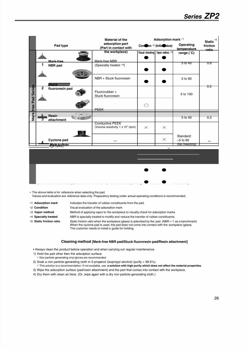
8/12/2019 Ventosa Especial Da Smc
http://slidepdf.com/reader/full/ventosa-especial-da-smc 56/119
Adsorption mark characteristics [: Little or no influence : Can be used depending on the conditions. : Not suitable]
– –
5 to 40
5 to 40 0.6
5 to 60
0.2
5 to 100
0.2
–Made to Order
• Always clean the product before operation and when carrying out regular maintenance.
1) Hold the part other than the adsorption surface.∗ Non particle-generating vinyl gloves are recommended.
2) Soak a non particle-generating cloth in 2-propanol (isopropyl alcohol) (purity > 99.5%).∗ This solution is a recommendation. If not available, use a solution with high purity which does not affect the material properties.
3) Wipe the adsorption surface (pad/resin attachment) and the part that comes into contact with the workpiece.
4) Dry them with clean air blow. (Or, wipe again with a dry non particle-generating cloth.)
Cleaning method [Mark-free NBR pad/Stuck fluororesin pad/Resin attachment]
Series ZP2
Material of the
adsorption part
(Part in contact with
the workpiece)
Pad type Operating
temperature
range (°C)Visual checking
Adsorption mark ∗1
Vapor method ∗3
Condition ∗2 (Initial value)
Static
friction
ratio
∗5
S t a n d a r d
M a r k - f r e e P a d S e r i e s
Series ZP(Standard material)
Stuck
fluororesin pad
Resin
attachment
Cyclone pad
Mark-free
NBR pad
NBR
Fluororubber
Conductive NBR/Silicone rubber
Silicone rubber
Urethane rubber
Mark-free NBR
(Specially treated ∗4)
NBR + Stuck fluororesin
Fluororubber +
Stuck fluororesin
PEEK
Conductive PEEK(Volume resistivity: 1 x 10⁶ Ωcm)
—
Standard:
–5 to 60
(No freezing)
∗ The above table is for reference when selecting the pad.
Values and evaluation are reference data only. Preparatory testing under actual operating conditions is recommended.
∗1 Adsorption mark Indicates the transfer of rubber constituents from the pad.
∗2 Condition Visual evaluation of the adsorption mark
∗3 Vapor method Method of applying vapor to the workpiece to visually check for adsorption marks
∗4 Specially treated NBR is specially treated to modify and reduce the transfer of rubber constituents.∗5 Static friction ratio Static friction ratio when the workpiece (glass) is adsorbed by the pad. (NBR = 1 as a benchmark)
When the cyclone pad is used, the pad does not come into contact with the workpiece (glass).The customer needs to install a guide for holding.
1
3
2
4
26

8/12/2019 Ventosa Especial Da Smc
http://slidepdf.com/reader/full/ventosa-especial-da-smc 57/119
If an adapter will be made by the customer, design the adapter with the dimensions shown below.
Adapter Mounting Dimensions
Note) R part has to be smooth with no corners.∗ Refer to page 66 for adapter applicable to the ZP series.
Applicable pad
04U/06U/08UApplicable pad
10U/16UApplicable pad
25U/32UApplicable pad
40U/50U
1 2
Y
ø7
øC
øA
øB
E
Y
øD
øC
øA
øB
R R
R
R
R
ø8
ø9
ø11.7
2 . 7
1 0
. 5
9 . 5
ø4.5
ø11.7
R
ø2.5
ø3.8
ø4.9
2
0 . 5
6 7
R
2 5 °
2 5 °
ø4.9
ø2.5
ø4.5
ø5
ø6.6
1
R R
R
7 8
R
R
R R
R
R
R
ø3.5
ø5
ø6
ø7.9
2
8 9
R
3 0 °
3 0 °
3 0 °
4 5 °
4 5 °
4 5
°
ZP2-04 to 08UCL ZP2-10 to 50UCL
Dimensions
A4
6
8
B4.8
7
9
C1.6
2.5
Y
0.8
1
ZP2-04UCLZP2-06UCLZP2-08UCL
Model
Dimensions
A10
16
25
32
40
50
B12
18
28
35
43
53
C
4
7
D
13
15
18
E12
12.5
14
14.5
18.5
19.5
Y3
3.5
4
4.5
6.5
7.5
ZP2-10UCLZP2-16UCLZP2-25UCLZP2-32UCLZP2-40UCLZP2-50UCL
Model
Pad diameter
040608101625324050
ø4
ø6
ø8
ø10
ø16
ø25
ø32
ø40
ø50
Symbol Pad diameter
ZP2 04 U CLPad unit
Pad type
UType
FlatSymbol
Pad material
CLMaterial
Mark-free NBRSymbol
Mark-free Padø4, ø6, ø8, ø10, ø16, ø25, ø32, ø40, ø50
With/Without lock ring
X19
Lock ring
Note) ø10 or larger
U: Flat
Pad which reduces the
adsorption marks left on the
workpiece by rubber
The pad is made from mark-
free NBR, and the NBR is then
specially treated to minimize
the transfer of rubber
constituents to the workpiece.
Applicable for the ZP series
adapter
How to Order
X19With lock ring
Without lock ring Note)
Nill
Dimensions: Pad Unit
Symbol/Type
Pad diameter
27

8/12/2019 Ventosa Especial Da Smc
http://slidepdf.com/reader/full/ventosa-especial-da-smc 58/119
How to Order
Dimensions
A100
125
B103
128
C 80
104
ZP2-100HZP2-125H
Model
Dimensions
A40
50
B43
53
C32
42
ZP2-40HZP2-50H
Model
Dimensions
A63
80
B65
82
C50
61
D14.5
16.5
Y3.5
4.5
ZP2-63HZP2-80H
Model
4 0
4 x 9 .5
4 x 6
3 x 6 .5
3 x 4
1 8
4 x 8
4 x 5
3 4
1 1
. 5
3 3 . 5
3 . 5
øC
øA
ø6
øB
Y
4 . 5
4 . 5
D
øC
øA
ø8
øB
2 1
7 . 5
6
5 . 5
øC
øA
ø10
øB
ZP2- H4050 ZP2- H63
80 ZP2- H100125
Pad which reduces the
adsorption marks left on the
workpiece by rubber
The pad is made from mark-
free NBR, and the NBR is then
specially treated to minimize
the transfer of rubber
constituents to the workpiece.
Prevents rubber constituents
of the pad from transferring by
baking the fluororesin sheet to
the adsorption surface.
Pad diameter
40506380
100125
ø40
ø50
ø63
ø80
ø100
ø125
Symbol Pad diameter
Pad material
CLNTFT
MaterialMark-free NBR
NBR + Stuck fluororesin
Fluororubber + Stuck fluororesin
Symbol
ZP2 40 H CL
Pad type
HType
Heavy-duty (Flat with rib)Symbol
Stuck fluororesin
Mark-free Padø40, ø50, ø63, ø80, ø100, ø125
H: Heavy-duty(Flat with rib)
Symbol/Type
Pad diameter
Dimensions: Pad Unit
Pad unit
28

8/12/2019 Ventosa Especial Da Smc
http://slidepdf.com/reader/full/ventosa-especial-da-smc 59/119
F
Y
E
D
øB
øA
øC
How to Order No adsorption marks (rubber constituents)
are left on the workpiece.Avoids direct contact between the workpiece and therubber by installing a PEEK attachment to the bellowspad to prevent the transfer of rubber constituents.
Prevents sticking of the pad (rubber) and the
workpiece.
Ideal for the ZP series bellows pad (ø6 to ø32)
DimensionsA 6
8
10
13
1620
25
32
B 7
9
12
15
1822
27
34
C 1.6
3
3.5
4
8
10
D
0.5
1
E
3
3.5
5.5
6
8.5
11.5
F
13.5
16.5
19
20.524.5
25
30
Y
0.5
1
ZP2-06KZP2-08KZP2-10KZP2-13K
ZP2-16KZP2-20KZP2-25KZP2-32K
Model
ZP06BZP08BZP10BZP13B
ZP16BZP20BZP25BZP32B
Applicable pad
ZP2 06 K PPad diameter
0608101316202532
ZP06BZP08BZP10BZP13BZP16BZP20BZP25BZP32B
Symbol Pad diameter
Attachment material
PGP
Material
PEEK
Conductive PEEK
Symbol
Resin Attachmentø6, ø8, ø10, ø13, ø16, ø20, ø25, ø32Pad diameter
How to Order (When ordering with a pad)
Attachment
Bellows pad
When ordering with a pad, put “∗”, below the part number of the pad as shownbelow. Note that the pad is not delivered with the attachment assembled.
This attachment can only be assembled onto SMC’s standard bellows pad.
When the attachment is made of conductive PEEK, use conductive material forthe pad.
Orderingexample
ZPT06BNJ10-B5-A8
∗ ZP2-06KP
Bellows pad part no.
Resin attachment part no.
Dimensions
«Precautions»Clean the product before using the attachment.This product is not cleaned after machining. If the product is used in thecondition in which it is shipped, residual material may be left on the workpieces. Clean before usage. If you have any questions, please contactSMC.
• If contact with hard material is a problem, do not use this product.• PEEK material and cut parts fall under the security trade control.
Note 1) in the table indicates the attachment material.
Note 2) in the table indicates the pad material.
29

8/12/2019 Ventosa Especial Da Smc
http://slidepdf.com/reader/full/ventosa-especial-da-smc 60/119
ø1.5
ø4
5 5
ø3
ø6
5
ø4
ø8
5
ø10
ø6
5
ø15
ø10
4
1 .
5
ø4.9
ø4.1ø2.5
6 0 °
4
1
. 5
ø3.9
ø1.5ø3.1
6 0 °
4
1
. 5
ø0.8ø1.6
ø2.1
7 0
°
ø4.1
4
ø10.9
ø10.1 1
. 5
6 0 °
ø4.1
4
ø6.9
ø6.1 1
. 5
6 0
°
How to Order
Sponge Padø4, ø6, ø8, ø10, ø15
ZP2 06 SPad material
GSGC
Conductive silicone
Conductive CR
Symbol Material
GSPad O.D.
0406081015
ø4
ø6
ø8
ø10
ø15
Symbol Pad diameter
ZP2-15S
ZP2-04S
ZP2-10S
ZP2-06S ZP2-08S
For adsorption of work pieceswith bumps
Applicable pad
04SApplicable pad
06SApplicable pad
08SApplicable pad
10SApplicable pad
15S
If an adapter will be made by the customer, design the adapter with the dimensions shown below.
Adapter Mounting Dimensions
∗ Refer to pages 70 and 71 for adapter applicable to the ZP2 series.
Pad diameter
Symbol/Type
S: Sponge
Pad unit
Pad type
SType
SpongeSymbol
Dimensions: Pad Unit
30

8/12/2019 Ventosa Especial Da Smc
http://slidepdf.com/reader/full/ventosa-especial-da-smc 61/119
Width across flat 5
(Hexagon)
ø4
ø0.8
5
( 1 0 )
M3 x 0.5
2 . 5
2 . 5
ø1.5
Width across flat 7
(Hexagon)
ø6
ø1.5
5
( 1 1 )
M5 x 0.8
2 . 5
3 . 5
ø3
Width across flat 8
(Hexagon)
ø8
ø2.5
5
( 1 1 )
M5 x 0.8
2 . 5
3 . 5
ø4
1 1 1
How to Order
ZP2-T04S-A3 ZP2-T06S-A5 ZP2-T08S-A5
06 S A3
Mounting
GSZP2 T
Replacement Part No.Pad unit part no.
ZP2-04SZP2-06SZP2-08SZP2-10SZP2-15SZP2-04SZP2-06SZP2-08SZP2-10SZP2-15S
Adapter part no.
ZP2A-S01P
ZP2A-S02P
ZP2A-S03P
ZP2A-S04P
ZP2A-S05P
ZP2A-S11ZP2A-S12
ZP2A-S13
ZP2A-S14
ZP2A-S15
ZP2-T04S-A3ZP2-T06S-A5ZP2-T08S-A5ZP2-T10S-A5ZP2-T15S-A5
ZP2-T04S-B3ZP2-T06S-B5ZP2-T08S-B5ZP2-T10S-B5ZP2-T15S-B5
Model
Pad O.D.
0406081015
ø4
ø6
ø8
ø10
ø15
Symbol Pad diameter
Note) in the table indicates the pad material.
A3A5B3B5
M3 x 0.5 (Male thread)
M5 x 0.8 (Male thread)
M3 x 0.5 (Female thread)
M5 x 0.8 (Female thread)
—
—
—
—
—
—
—
—
—
—
Symbol Thread sizeApplicable pad O.D. symbol
04 06 08 10 15
Vacuum inlet direction
TDirection
Vertical
Symbol
Pad type
SType
SpongeSymbol
Pad material
GSGC
Conductive silicone
Conductive CR
Symbol Material
Dimensions: With Adapter
31
Series ZP2
With adapter

8/12/2019 Ventosa Especial Da Smc
http://slidepdf.com/reader/full/ventosa-especial-da-smc 62/119

8/12/2019 Ventosa Especial Da Smc
http://slidepdf.com/reader/full/ventosa-especial-da-smc 63/119
1 4
8
2ø5
ø32
ø34
3 x 3
3 x 5
2 . 5
2
ø26
ø52
ø340
ø344
5 0
ø276
8 8
4 x 1 4 4 x 9
2 3
1 1
1 0 4
5
ø298
ø52
ø301
1 9
1 3
1 0
ø160
4 x M8 x 1.25
ø240
8 8
4 x 1 4 4 x 9
How to Order
Heavy-duty Padø32, ø150, ø250, ø300, ø340
ZP2 32 H NPad diameter
32150250300340
Pad diameter
ø32
ø150
ø250
ø300
ø340
Symbol
Pad material
NSFC
Material
NBR
Silicone rubber
FKM
CR
Symbol
ZP2-32H
Reinforced pad to prevent
deformation when transferring
heavy or large work pieces
Note) Silicone rubber is only applicable
to the ø32 pad.
H (Flat with rib)
HT (Thin flat with rib)
32
—
Pad diameter(Symbol)Pad type 150
—
250
—
300
—
340
—
Pad type—Pad diameter
ZP2-300H ZP2-340H
H: Heavy-duty(Flat with rib)
HT: Heavy-duty(Thin flat with rib)Pad diameter
Symbol/Type
Pad unit
Dimensions: Pad Unit
33
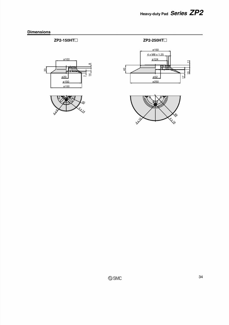
8/12/2019 Ventosa Especial Da Smc
http://slidepdf.com/reader/full/ventosa-especial-da-smc 64/119
3 3
ø103
ø20
ø150
ø155
7
8
1 4
4 0
4 x 1 4 4
x 9
ø250
ø52
4 0
1 7
ø150
1 1
1 0
8 8 4 x 1 6
4 x 1 0
4 x M8 x 1.25
ø124
ZP2-150HT ZP2-250HT
Dimensions
34
Series ZP2 Heavy-duty Pad

8/12/2019 Ventosa Especial Da Smc
http://slidepdf.com/reader/full/ventosa-especial-da-smc 65/119
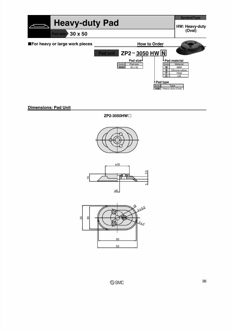
8/12/2019 Ventosa Especial Da Smc
http://slidepdf.com/reader/full/ventosa-especial-da-smc 66/119
50
53
1 8
ø6
3
3 . 5
1 0
3 0
3 3
ø32
3 x 6. 5
3 x 4
How to Order
Pad size 30 x 50
ZP2 3050 HW NPad size
3050Pad size
30 x 50
Symbol
ZP2-3050HW
For heavy or large work pieces
HW: Heavy-duty(Oval)
Heavy-duty PadSymbol/Type
Pad unit
Pad typeSymbol
HWType
Heavy-duty (Oval)
Pad material
NSFC
Material
NBR
Silicone rubber
FKM
CR
Symbol
Dimensions: Pad Unit
36
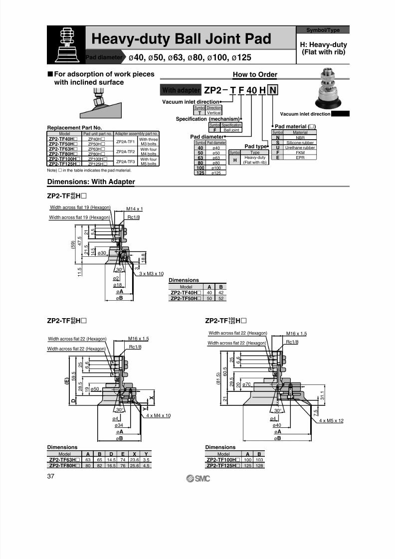
8/12/2019 Ventosa Especial Da Smc
http://slidepdf.com/reader/full/ventosa-especial-da-smc 67/119
Width across flat 19 (Hexagon)
Width across flat 19 (Hexagon)
3 x M3 x 10
Rc1/8
5
5 2 1
( 5 9 )
30°
ø2
ø18
øA
øB
3
1
8 . 8
ø30
1 1
. 5
1 4 .
5
2 1
. 5
M14 x 1
4 7
. 5
4 x M4 x 10
Rc1/8
Width across flat 22 (Hexagon)
Width across flat 22 (Hexagon)
2 5 6
6
5 9
. 5
( E )
30°
ø4
ø34
øA
øB
Y
X
ø50
D
1 9 2
8 . 5
M16 x 1.5
4 x M5 x 12
Width across flat 22 (Hexagon)
Width across flat 22 (Hexagon)
Rc1/8
( 8 1
. 5 )
6 0
. 5
øB
øA
ø40
ø4
30° 7
. 5
3 1
. 1
ø70
2 1
2 0 2
9 . 5
2 5
6 6
M16 x 1.5
Vacuum inlet direction
TDirection
Vertical
Symbol
How to Order
Heavy-duty Ball Joint Padø40, ø50, ø63, ø80, ø100, ø125
For adsorption of work pieceswith inclined surface
Replacement Part No.Pad unit part no.
ZP40HZP50HZP63HZP80HZP100HZP125H
Adapter assembly part no.
ZP2A-TF1
ZP2A-TF2
ZP2A-TF3
ZP2-TF40HZP2-TF50HZP2-TF63HZP2-TF80HZP2-TF100HZP2-TF125H
Model
F 40 NHZP2 T
Specification (mechanism)
FSpecification
Ball joint
Symbol Pad material ()
NSUFE
Material
NBR
Silicone rubber
Urethane rubber
FKM
EPR
Symbol
H
Type
Heavy-duty
(Flat with rib)
Symbol
Pad type
Pad diameter
40506380
100
125
Pad diameter
ø40
ø50
ø63
ø80
ø100
ø125
Symbol
Vacuum inlet direction Vertical
ZP2-TF H4050
ZP2-TF H6380 ZP2-TF H100
125
Dimensions
A40
50
B42
52
ZP2-TF40HZP2-TF50H
Model
Dimensions
A100
125
B103
128
ZP2-TF100HZP2-TF125H
Model
Dimensions
A63
80
B65
82
ZP2-TF63HZP2-TF80H
Model D14.5
16.5
E74
76
X23.6
25.6
Y3.5
4.5
Note) in the table indicates the pad material.
With threeM3 bolts
With fourM4 bolts
With fourM5 bolts
Pad diameter
Symbol/Type
With adapter
Dimensions: With Adapter
H: Heavy-duty(Flat with rib)
37

8/12/2019 Ventosa Especial Da Smc
http://slidepdf.com/reader/full/ventosa-especial-da-smc 68/119
M5 x 0.8
Width across flat 19 (Hexagon)
3 x M3 x 10
5 9
. 5
( 7 1 )
øB
øA
ø18
ø230°
3
ø30
1 1 . 5
1 4 .
5
2 1
. 5
5
5 2 1
M14 x 1
1 8
. 8
3 2
Rc1/8
Width across flat 22 (Hexagon)
4 x M4 x 10
4 5
8 0
. 5
( E )
øB
øA
ø34
ø4
30° Y
X
ø50
D
2 8
. 5
1 9
M16 x 1.5
6
6 2 5
4 x M5 x 12
Rc1/8
Width across flat 22 (Hexagon)
( 1 0 2
. 5 )
8 1
. 5
øB
øA
ø40
ø4
30° 7
. 5
ø70
3 1
. 1
2 1
2 0
M16 x 1.5
6 6 2
5
2 9
. 5 4 6
How to Order
Replacement Part No.Pad unit part no.
ZP40HZP50HZP63HZP80HZP100HZP125H
Adapter assembly part no.
ZP2A-XF1ZP2-XF40HZP2-XF50HZP2-XF63HZP2-XF80HZP2-XF100HZP2-XF125H
Model
Note) in the table indicates the pad material.
F 40 NHZP2 XPad material ()
HType
Heavy-duty (Flat with rib)
Symbol
Pad type
Pad diameter
40506380100125
Pad diameter
ø40
ø50
ø63
ø80
ø100
ø125
Symbol
Dimensions
A40
50
B42
52
ZP2-XF40HZP2-XF50H
Model
Dimensions
A100
125
B103
128
ZP2-XF100HZP2-XF125H
Model
Dimensions
A63
80
B65
82
ZP2-XF63HZP2-XF80H
Model D14.5
16.5
E95
97
X23.6
25.6
Y3.5
4.5
ZP2-XF H4050
ZP2-XF H6380 ZP2-XF H100
125
ZP2A-XF2
ZP2A-XF3
With threeM3 bolts
With fourM4 bolts
With fourM5 bolts
With adapter
Vacuum inlet direction
XDirectionLateral
Symbol
Specification (mechanism)
FSpecification
Ball jointSymbol
NSUFE
Material
NBR
Silicone rubber
Urethane rubber
FKM
EPR
Symbol
Vacuum inlet direction Lateral
Dimensions: With Adapter
38
Series ZP2 Heavy-duty Ball Joint Pad

8/12/2019 Ventosa Especial Da Smc
http://slidepdf.com/reader/full/ventosa-especial-da-smc 69/119
How to Order
Pad diameter
Replacement Part No.Pad unit part no.
ZP40H
ZP50H
ZP63H
ZP80H
ZP100H
ZP125H
Buffer assembly part no.
ZP2B-TF1(JB/JF)25
ZP2B-TF1(JB/JF)50
ZP2B-TF1(JB/JF)75
ZP2B-TF1(JB/JF)25
ZP2B-TF1(JB/JF)50
ZP2B-TF1(JB/JF)75
ZP2B-TF2(JB/JF)25
ZP2B-TF2(JB/JF)50
ZP2B-TF2(JB/JF)75
ZP2B-TF2(JB/JF)100
ZP2B-TF2(JB/JF)25
ZP2B-TF2(JB/JF)50
ZP2B-TF2(JB/JF)75
ZP2B-TF2(JB/JF)100
ZP2B-TF3(JB/JF)25
ZP2B-TF3(JB/JF)50
ZP2B-TF3(JB/JF)75
ZP2B-TF3(JB/JF)100
ZP2B-TF3(JB/JF)25
ZP2B-TF3(JB/JF)50
ZP2B-TF3(JB/JF)75
ZP2B-TF3(JB/JF)100
ZP2-TF40H(JB/JF)25ZP2-TF40H(JB/JF)50ZP2-TF40H(JB/JF)75ZP2-TF50H(JB/JF)25ZP2-TF50H(JB/JF)50ZP2-TF50H(JB/JF)75ZP2-TF63H(JB/JF)25ZP2-TF63H(JB/JF)50ZP2-TF63H(JB/JF)75ZP2-TF63H(JB/JF)100ZP2-TF80H(JB/JF)25ZP2-TF80H(JB/JF)50ZP2-TF80H(JB/JF)75ZP2-TF80H(JB/JF)100ZP2-TF100H(JB/JF)25ZP2-TF100H(JB/JF)50ZP2-TF100H(JB/JF)75ZP2-TF100H(JB/JF)100ZP2-TF125H(JB/JF)25ZP2-TF125H(JB/JF)50ZP2-TF125H(JB/JF)75ZP2-TF125H(JB/JF)100
Model
F 40 N 25H JBZP2 T
Pad material (
)NSUFE
Material
NBR
Silicone rubber
Urethane rubber
FKM
EPR
Symbol
Buffer specification
JB
JF
Specification
RotatingWith bushing
Material: Brass
RotatingWith bushing
Material: Steel
Symbol
HTypeSymbol
Pad type
255075
100
ZP40HZP50H
ApplicablepadStroke
ZP63HZP80H
ZP100HZP125H
Buffer stroke ()
Note) in the table indicates the pad material.
ø40, ø50
6.9 N
11.8 N
Tightening torque : 28 to 32 N·m
Tightening torque : 48 to 52 N·m
At 0 stroke
At Full stroke
JB
JF
Stroke (mm)
Spring reactive force
Buffer specifications
ø63, ø80, ø100, ø125
10 N
15 N
Tightening torque : 45 to 50 N·m
Tightening torque : 75 to 80 N·m
Pad diameter
40506380
100125
Pad diameter
ø40
ø50
ø63
ø80
ø100
ø125
Symbol
Buffer Specifications
25, 50, 75 25, 50, 75, 100
RotatingWith bushing
Buffer body material: Brass
RotatingWith bushing
Buffer body material: Steel
Heavy-duty (Flat with rib)
With threeM3 bolts
With fourM4 bolts
With fourM5 bolts
With buffer
Vacuum inlet direction
TDirectionVertical
Symbol
Specification (mechanism)
FSpecification
Ball jointSymbol
Vacuum inlet direction Vertical
—
39
Series ZP2

8/12/2019 Ventosa Especial Da Smc
http://slidepdf.com/reader/full/ventosa-especial-da-smc 70/119
Width across flat 27
(Hexagon)
Width across flat 14 (Hexagon)
Width across flat 13
(Hexagon)
3 x M3 x 10
Rc1/8
9
9
M18 x 1.5
D
2 0
. 5
3
øB
øA
ø18
ø2
1 8 . 8
1 1
. 5
1 4
. 5
2 1
. 5
( E )
4 2
. 5
30°
ø30
3 5
Width across flat 17
(Hexagon)
Width across flat 30(Hexagon)
4 x M4 x 10
Width across flat 17 (Hexagon) Rc1/8
8
8
2 4
E
M22 x 1.5
ø34
øA
øB
ø4
D
1 9 2
8 . 5 5
4 . 5
( F )
30°
ø50
Y
X
5 0
Width across flat 17 (Hexagon)
Width across flat 30(Hexagon)
Width across flat 17
(Hexagon)
4 x M5 x 12
Rc1/8
8
8
2 4
D
M22 x 1.5
2 1
øA
7 . 5
ø40
øB
ø4
2 0 2
9 . 5 5 5
. 5
( E )
3 1
. 1
ø70
30°
5 0
Bushing
BushingBushing
Dimensions: With Buffer
DimensionsA
40
50
B
42
52
ZP2-TF40H(JB/JF)25ZP2-TF40H(JB/JF)50ZP2-TF40H(JB/JF)75ZP2-TF50H(JB/JF)25ZP2-TF50H(JB/JF)50ZP2-TF50H(JB/JF)75
Model D 40
75
111
40
75
111
E149.5
184.5
220.5
149.5
184.5
220.5
DimensionsA
63
80
B
65
82
ZP2-TF63H(JB/JF)25ZP2-TF63H(JB/JF)50ZP2-TF63H(JB/JF)75ZP2-TF63H(JB/JF)100ZP2-TF80H(JB/JF)25ZP2-TF80H(JB/JF)50ZP2-TF80H(JB/JF)75ZP2-TF80H(JB/JF)100
Model D
14.5
16.5
E 44
80
120
155
44
80
120
155
F187
223
263
298
189
225
265
300
X
23.6
25.6
Y
3.5
4.5
DimensionsA
100
125
B
103
128
ZP2-TF100H(JB/JF)25ZP2-TF100H(JB/JF)50ZP2-TF100H(JB/JF)75ZP2-TF100H(JB/JF)100ZP2-TF125H(JB/JF)25ZP2-TF125H(JB/JF)50ZP2-TF125H(JB/JF)75ZP2-TF125H(JB/JF)100
Model D 44
80
120
155
44
80
120
155
E194.5
230.5
270.5
305.5
194.5
230.5
270.5
305.5
ZP2-TF H JBJF
4050
ZP2-TF H JBJF
6380 ZP2-TF H JB
JF100125
40
Series ZP2 Heavy-duty Ball Joint Pad
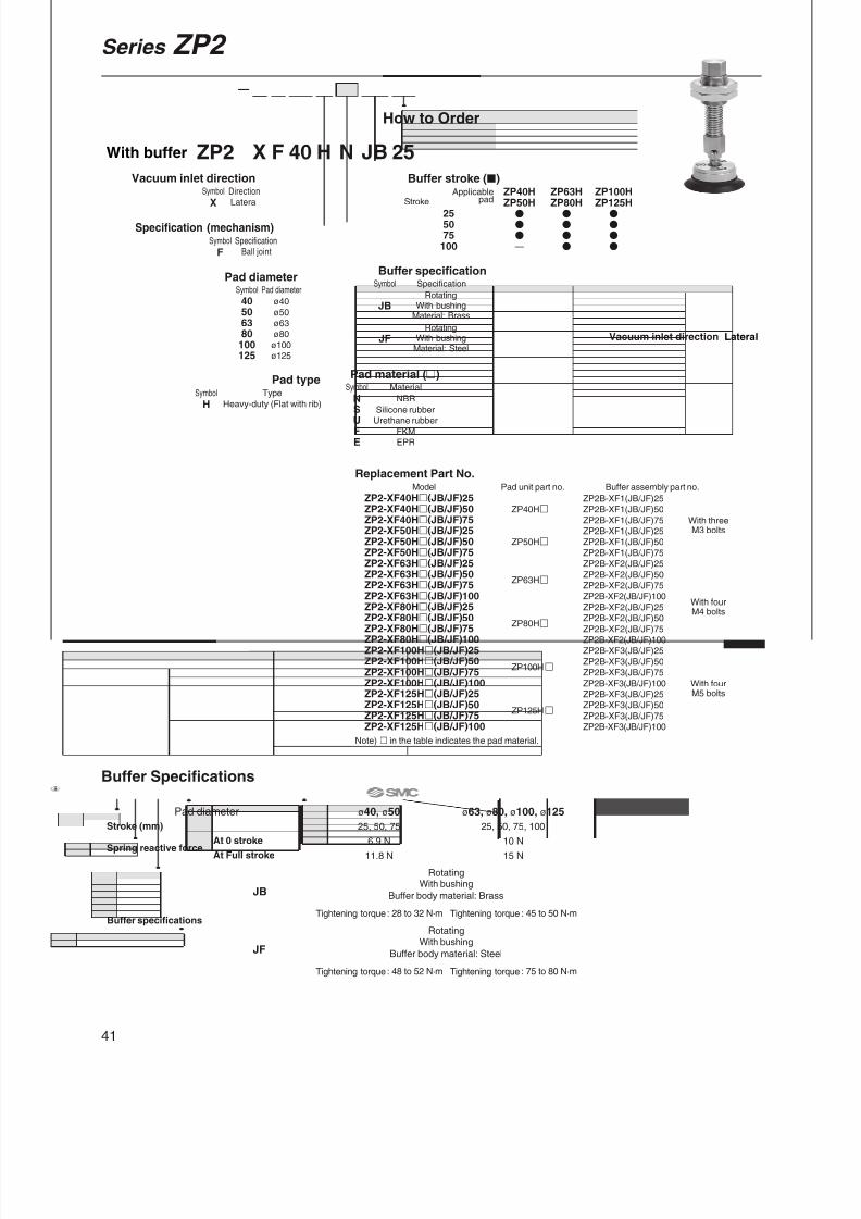
8/12/2019 Ventosa Especial Da Smc
http://slidepdf.com/reader/full/ventosa-especial-da-smc 71/119
How to Order
Replacement Part No.Pad unit part no.
ZP40H
ZP50H
ZP63H
ZP80H
ZP100H
ZP125H
Buffer assembly part no.
ZP2B-XF1(JB/JF)25
ZP2B-XF1(JB/JF)50
ZP2B-XF1(JB/JF)75
ZP2B-XF1(JB/JF)25
ZP2B-XF1(JB/JF)50
ZP2B-XF1(JB/JF)75
ZP2B-XF2(JB/JF)25
ZP2B-XF2(JB/JF)50
ZP2B-XF2(JB/JF)75
ZP2B-XF2(JB/JF)100
ZP2B-XF2(JB/JF)25
ZP2B-XF2(JB/JF)50
ZP2B-XF2(JB/JF)75
ZP2B-XF2(JB/JF)100
ZP2B-XF3(JB/JF)25
ZP2B-XF3(JB/JF)50
ZP2B-XF3(JB/JF)75
ZP2B-XF3(JB/JF)100
ZP2B-XF3(JB/JF)25
ZP2B-XF3(JB/JF)50
ZP2B-XF3(JB/JF)75
ZP2B-XF3(JB/JF)100
ZP2-XF40H(JB/JF)25ZP2-XF40H(JB/JF)50ZP2-XF40H(JB/JF)75ZP2-XF50H(JB/JF)25ZP2-XF50H(JB/JF)50ZP2-XF50H(JB/JF)75ZP2-XF63H(JB/JF)25ZP2-XF63H(JB/JF)50ZP2-XF63H(JB/JF)75ZP2-XF63H(JB/JF)100ZP2-XF80H(JB/JF)25ZP2-XF80H(JB/JF)50ZP2-XF80H(JB/JF)75ZP2-XF80H(JB/JF)100ZP2-XF100H(JB/JF)25ZP2-XF100H(JB/JF)50ZP2-XF100H(JB/JF)75ZP2-XF100H(JB/JF)100ZP2-XF125H(JB/JF)25ZP2-XF125H(JB/JF)50ZP2-XF125H(JB/JF)75ZP2-XF125H(JB/JF)100
Model
Note) in the table indicates the pad material.
F 40 N 25H JBZP2 X
255075
100
ZP40HZP50H
—
ApplicablepadStroke
ZP63HZP80H
ZP100HZP125H
Buffer stroke ()
With buffer
Vacuum inlet direction
XDirectionLateral
Symbol
Specification (mechanism)
FSpecification
Ball jointSymbol
Pad diameter
40506380
100125
Pad diameter
ø40
ø50
ø63
ø80
ø100
ø125
Symbol
HTypeSymbol
Pad type
Heavy-duty (Flat with rib)
Buffer specification
JB
JF
Specification
RotatingWith bushing
Material: Brass
RotatingWith bushing
Material: Steel
Symbol
Pad material (
)NSUFE
Material
NBR
Silicone rubber
Urethane rubber
FKM
EPR
Symbol
Vacuum inlet direction Lateral
With threeM3 bolts
With fourM4 bolts
With fourM5 bolts
Pad diameter ø40, ø50
6.9 N
11.8 N
Tightening torque : 28 to 32 N·m
Tightening torque : 48 to 52 N·m
At 0 stroke
At Full stroke
JB
JF
Stroke (mm)
Spring reactive force
Buffer specifications
ø63, ø80, ø100, ø125
10 N
15 N
Tightening torque : 45 to 50 N·m
Tightening torque : 75 to 80 N·m
Buffer Specifications
25, 50, 75 25, 50, 75, 100
RotatingWith bushing
Buffer body material: Brass
RotatingWith bushing
Buffer body material: Steel
41
Series ZP2

8/12/2019 Ventosa Especial Da Smc
http://slidepdf.com/reader/full/ventosa-especial-da-smc 72/119
M5 x 0.8
3 x M3 x 10
3 2
9
9
M18 x 1.5
D
1 6
3
øB
øA
ø18
ø2 1 1
. 5 30°
1 8
. 8ø30
1 4
. 5
2 1
. 5 5 0
. 5
3 5
( E )
Rc1/8
4 x M4 x 10
4 5
6 7 . 5
8
8
E
M22 x 1.5
30°
ø4
ø34
øB
øA
Y
ø50
X D
1 9 2
8 . 5
2 1
( F )
5 0
4 x M5 x 12
Rc1/8
4 6 6
8 . 5
( E )
øB
øA
ø4
30°
ø40
7 . 5
3 1
. 1
ø70
2 1
2 0 2
9 . 5
D
2 1
8
8 5 0
M22 x 1.5
Width across flat 27(Hexagon)
Width across flat 14 (Hexagon)
Width across flat 13
(Hexagon)
Bushing
Width across flat 22
(Hexagon)
Width across flat 30(Hexagon)
Width across flat 17 (Hexagon)
Bushing
Width across flat 17 (Hexagon)
Width across flat 30(Hexagon)
Width across flat 22
(Hexagon)
Bushing
DimensionsA
40
50
B
42
52
ZP2-XF40H(JB/JF)25ZP2-XF40H(JB/JF)50ZP2-XF40H(JB/JF)75ZP2-XF50H(JB/JF)25ZP2-XF50H(JB/JF)50ZP2-XF50H(JB/JF)75
Model D 40
75
111
40
75
111
E153
188
224
153
188
224
DimensionsA
63
80
B
65
82
ZP2-XF63H(JB/JF)25ZP2-XF63H(JB/JF)50ZP2-XF63H(JB/JF)75ZP2-XF63H(JB/JF)100ZP2-XF80H(JB/JF)25ZP2-XF80H(JB/JF)50ZP2-XF80H(JB/JF)75ZP2-XF80H(JB/JF)100
Model D
14.5
16.5
E 44
80
120
155
44
80
120
155
F197
233
273
308
199
235
275
310
X
23.6
25.6
Y
3.5
4.5
DimensionsA
100
125
B
103
128
ZP2-XF100H(JB/JF)25ZP2-XF100H(JB/JF)50ZP2-XF100H(JB/JF)75ZP2-XF100H(JB/JF)100ZP2-XF125H(JB/JF)25ZP2-XF125H(JB/JF)50ZP2-XF125H(JB/JF)75ZP2-XF125H(JB/JF)100
Model D 44
80
120
155
44
80
120
155
E204.5
240.5
280.5
315.5
204.5
240.5
280.5
315.5
ZP2-XF H JBJF
4050
ZP2-XF H JBJF
6380 ZP2-XF H JB
JF100125
Dimensions: With Buffer
Series ZP2 Heavy-duty Ball Joint Pad
42

8/12/2019 Ventosa Especial Da Smc
http://slidepdf.com/reader/full/ventosa-especial-da-smc 73/119
Width across flat 19 (Hexagon)
Width across flat 19(Hexagon)
Rc1/8
3 x M3 x 10
5
5 2 1
ø30
1 4
. 5
2 1
. 5
M14 x 1
øE
øB
øA
øD
ø18
ø2
30°
Y X
F
( G ) 4
7 . 5
4 x M4 x 10
Rc1/8
Width across flat 22 (Hexagon)
Width across flat 22 (Hexagon)
2 5 6
6
5 9
. 5
ø50 1 9 2
8 . 5
M16 x 1.5
øE
øB
øA
øD
ø34
ø4
30°
Y
X F
( G )
4 x M5 x 12
Width across flat 22 (Hexagon)
Width across flat 22 (Hexagon) Rc1/8
6 0
. 5
ø70 2 0 2
9 . 5
2 5
6 6
M16 x 1.5
F
( G )
øE
øB
øA
øD
ø40
ø4
30°
Y
X
How to Order
Heavy-duty Ball Joint Padø40, ø50, ø63, ø80, ø100, ø125
Replacement Part No.Pad unit part no.
ZP40HBZP50HBZP63HBZP80HBZP100HBZP125HB
Adapter assembly part no.
ZP2-TF40HBZP2-TF50HBZP2-TF63HBZP2-TF80HBZP2-TF100HBZP2-TF125HB
Model
F 40 NHBZP2 T
Specification (mechanism)
HB
Type
Heavy-duty(Bellows)
Symbol
Pad type
Pad diameter
40506380100125
Pad diameter
ø40
ø50
ø63
ø80
ø100
ø125
Symbol
For adsorption of work pieceswith inclined or curvedsurface
ZP2-TF HB4050
ZP2-TF HB6380 ZP2-TF HB100
125
Dimensions
A40
50
B41
52
ZP2-TF40HBZP2-TF50HB
Model D28
36
E43
54
F20.5
24
G68
71.5
X27.8
31.3
Y13
16.5
Dimensions
A63
80
B65
83
ZP2-TF63HBZP2-TF80HB
Model D46
58
E68
85
F31.5
37
G91
96.5
X40.6
46.1
Y21
27.5
Dimensions
A100
125
B103
129
ZP2-TF100HBZP2-TF125HB
Model D69
89
E107
135
F47.5
56
G108
116.5
X57.6
66.1
Y35.5
44
Note) in the table indicates the pad material.
ZP2A-TF1
ZP2A-TF2
ZP2A-TF3
With threeM3 bolts
With fourM4 bolts
With fourM5 bolts
HB: Heavy-duty(Bellows)
Pad diameter
Symbol/Type
With adapter
Vacuum inlet direction
TDirection
Vertical
Symbol
FSpecification
Ball joint
SymbolVacuum inlet direction Vertical
Pad material ()
NSUFE
Material
NBR
Silicone rubber
Urethane rubber
FKM
EPR
Symbol
Dimensions: With Adapter
43

8/12/2019 Ventosa Especial Da Smc
http://slidepdf.com/reader/full/ventosa-especial-da-smc 74/119
M5 x 0.8
Width across flat 19 (Hexagon)
3 x M3 x 10
5 9
. 5
ø30
1 4
. 5
2 1
. 5
5
5 2 1
M14 x 1
øE
øB
øA
øDø18
ø2
30°
Y X
F
( G )
3 2
Rc1/8
Width across flat 22 (Hexagon)
Width across flat 22 (Hexagon)
4 x M4 x 10
4 5
8 0 . 5
ø50 2 8
. 5
1 9
M16 x 1.5
6 6 2
5
øEøB
øA
øD
ø34
ø4
30°
F Y
X
( G )
4 x M5 x 12
Rc1/8
Width across flat 22 (Hexagon)
Width across flat 22 (Hexagon)
8 1
. 5
ø70 2 0
M16 x 1.5
6 6 2
5
2 9
. 5 4 6
( G )
F
øE
øB
øA
øD
ø40
ø4
30°
Y
X
How to Order
Replacement Part No.Pad unit part no.
ZP40HBZP50HBZP63HBZP80HBZP100HBZP125HB
Adapter assembly part no.
ZP2A-XF1
ZP2A-XF2
ZP2A-XF3
ZP2-XF40HBZP2-XF50HBZP2-XF63HBZP2-XF80HBZP2-XF100HBZP2-XF125HB
Model
Note) in the table indicates the pad material.
F 40 NHBZP2 X
Pad diameter
40506380100125
Pad diameter
ø40
ø50
ø63
ø80
ø100
ø125
Symbol
ZP2-XF HB4050
ZP2-XF HB6380 ZP2-XF HB100
125
Dimensions
A40
50
B41
52
ZP2-XF40HBZP2-XF50HB
Model D28
36
E43
54
F20.5
24
G80
83.5
X27.8
31.3
Y13
16.5
Dimensions
A63
80
B65
83
ZP2-XF63HBZP2-XF80HB
Model D46
58
E68
85
F31.5
37
G112
117.5
X40.6
46.1
Y21.5
27.5
Dimensions
A100
125
B103
129
ZP2-XF100HBZP2-XF125HB
Model D69
89
E107
135
F47.5
56
G129
137.5
X57.6
66.1
Y35.5
44
Vacuum inlet direction
XDirectionLateral
Symbol
Specification (mechanism)
FSpecification
Ball jointSymbol
Pad material ()
NSUFE
Material
NBR
Silicone rubber
Urethane rubber
FKM
EPR
Symbol
HBType
Heavy-duty (Bellows)
Symbol
Pad type
Vacuum inlet direction Lateral
With threeM3 bolts
With fourM4 bolts
With fourM5 bolts
Dimensions: With Adapter
44
Series ZP2 Heavy-duty Ball Joint Pad
With adapter

8/12/2019 Ventosa Especial Da Smc
http://slidepdf.com/reader/full/ventosa-especial-da-smc 75/119
How to Order
Replacement Part No.Pad unit part no.
ZP40HB
ZP50HB
ZP63HB
ZP80HB
ZP100HB
ZP125HB
Buffer assembly part no.
ZP2B-TF1(JB/JF)25
ZP2B-TF1(JB/JF)50
ZP2B-TF1(JB/JF)75
ZP2B-TF1(JB/JF)25
ZP2B-TF1(JB/JF)50
ZP2B-TF1(JB/JF)75
ZP2B-TF2(JB/JF)25
ZP2B-TF2(JB/JF)50
ZP2B-TF2(JB/JF)75
ZP2B-TF2(JB/JF)100
ZP2B-TF2(JB/JF)25
ZP2B-TF2(JB/JF)50
ZP2B-TF2(JB/JF)75
ZP2B-TF2(JB/JF)100
ZP2B-TF3(JB/JF)25
ZP2B-TF3(JB/JF)50
ZP2B-TF3(JB/JF)75
ZP2B-TF3(JB/JF)100
ZP2B-TF3(JB/JF)25
ZP2B-TF3(JB/JF)50
ZP2B-TF3(JB/JF)75
ZP2B-TF3(JB/JF)100
ZP2-TF40HB(JB/JF)25ZP2-TF40HB(JB/JF)50ZP2-TF40HB(JB/JF)75ZP2-TF50HB(JB/JF)25ZP2-TF50HB(JB/JF)50ZP2-TF50HB(JB/JF)75ZP2-TF63HB(JB/JF)25ZP2-TF63HB(JB/JF)50ZP2-TF63HB(JB/JF)75ZP2-TF63HB(JB/JF)100ZP2-TF80HB(JB/JF)25ZP2-TF80HB(JB/JF)50ZP2-TF80HB(JB/JF)75ZP2-TF80HB(JB/JF)100ZP2-TF100HB(JB/JF)25ZP2-TF100HB(JB/JF)50ZP2-TF100HB(JB/JF)75ZP2-TF100HB(JB/JF)100ZP2-TF125HB(JB/JF)25ZP2-TF125HB(JB/JF)50ZP2-TF125HB(JB/JF)75ZP2-TF125HB(JB/JF)100
Model
F 40 N 25HB JBZP2 T
Note) in the table indicates the pad material.
255075
100
ZP40HBZP50HB
—
ApplicablepadStroke
ZP63HBZP80HB
ZP100HBZP125HB
Buffer stroke ()Vacuum inlet direction
TDirectionVertical
Symbol
Specification (mechanism)
FSpecification
Ball jointSymbol
Pad diameter
40506380
100125
Pad diameter
ø40
ø50
ø63
ø80
ø100
ø125
Symbol
HBTypeSymbolPad type
Heavy-duty (Bellows)
Buffer specification
JB
JF
Specification
RotatingWith bushing
Material: Brass
RotatingWith bushing
Material: Steel
Symbol
Pad material (
)NSUFE
Material
NBR
Silicone rubber
Urethane rubber
FKM
EPR
Symbol
Vacuum inlet direction Vertical
With threeM3 bolts
With fourM4 bolts
With fourM5 bolts
Pad diameter ø40, ø50
6.9 N
11.8 N
Tightening torque : 28 to 32 N·m
Tightening torque : 48 to 52 N·m
At 0 stroke
At Full stroke
JB
JF
Stroke (mm)
Spring reactive force
Buffer specifications
ø63, ø80, ø100, ø125
10 N
15 N
Tightening torque : 45 to 50 N·m
Tightening torque : 75 to 80 N·m
Buffer Specifications
25, 50, 75 25, 50, 75, 100
RotatingWith bushing
Buffer body material: Brass
RotatingWith bushing
Buffer body material: Steel
45
Series ZP2
With buffer

8/12/2019 Ventosa Especial Da Smc
http://slidepdf.com/reader/full/ventosa-especial-da-smc 76/119

8/12/2019 Ventosa Especial Da Smc
http://slidepdf.com/reader/full/ventosa-especial-da-smc 77/119
Replacement Part No.Pad unit part no.
ZP40HB
ZP50HB
ZP63HB
ZP80HB
ZP100HB
ZP125HB
Buffer assembly part no.
ZP2B-XF1(JB/JF)25
ZP2B-XF1(JB/JF)50
ZP2B-XF1(JB/JF)75
ZP2B-XF1(JB/JF)25
ZP2B-XF1(JB/JF)50
ZP2B-XF1(JB/JF)75
ZP2B-XF2(JB/JF)25
ZP2B-XF2(JB/JF)50
ZP2B-XF2(JB/JF)75
ZP2B-XF2(JB/JF)100
ZP2B-XF2(JB/JF)25
ZP2B-XF2(JB/JF)50
ZP2B-XF2(JB/JF)75
ZP2B-XF2(JB/JF)100
ZP2B-XF3(JB/JF)25
ZP2B-XF3(JB/JF)50
ZP2B-XF3(JB/JF)75
ZP2B-XF3(JB/JF)100
ZP2B-XF3(JB/JF)25
ZP2B-XF3(JB/JF)50
ZP2B-XF3(JB/JF)75
ZP2B-XF3(JB/JF)100
ZP2-XF40HB(JB/JF)25ZP2-XF40HB(JB/JF)50ZP2-XF40HB(JB/JF)75ZP2-XF50HB(JB/JF)25ZP2-XF50HB(JB/JF)50ZP2-XF50HB(JB/JF)75ZP2-XF63HB(JB/JF)25ZP2-XF63HB(JB/JF)50ZP2-XF63HB(JB/JF)75ZP2-XF63HB(JB/JF)100ZP2-XF80HB(JB/JF)25ZP2-XF80HB(JB/JF)50ZP2-XF80HB(JB/JF)75ZP2-XF80HB(JB/JF)100ZP2-XF100HB(JB/JF)25ZP2-XF100HB(JB/JF)50ZP2-XF100HB(JB/JF)75ZP2-XF100HB(JB/JF)100ZP2-XF125HB(JB/JF)25ZP2-XF125HB(JB/JF)50ZP2-XF125HB(JB/JF)75ZP2-XF125HB(JB/JF)100
Model
Note) in the table indicates the pad material.
F 40 N 25HB JBZP2 X
255075
100
ZP40HBZP50HB
—
ZP63HBZP80HB
ZP100HBZP125HB
Buffer stroke ()
How to Order
With buffer
Vacuum inlet direction
TDirectionLateral
Symbol
Specification (mechanism)
FSpecification
Ball jointSymbol
Pad diameter
40506380
100125
Pad diameter
ø40
ø50
ø63
ø80
ø100
ø125
Symbol
HBTypeSymbolPad type
Heavy-duty (Bellows)
ApplicablepadStroke
Buffer specification
JB
JF
Specification
RotatingWith bushing
Material: Brass
RotatingWith bushing
Material: Steel
Symbol
Pad material (
)NSUFE
Material
NBR
Silicone rubber
Urethane rubber
FKM
EPR
Symbol
With threeM3 bolts
With fourM4 bolts
With fourM5 bolts
Pad diameter ø40, ø50
6.9 N
11.8 N
Tightening torque : 28 to 32 N·m
Tightening torque : 48 to 52 N·m
At 0 stroke
At Full stroke
JB
JF
Stroke (mm)
Spring reactive force
Buffer specifications
ø63, ø80, ø100, ø125
10 N
15 N
Tightening torque : 45 to 50 N·m
Tightening torque : 75 to 80 N·m
Buffer Specifications
25, 50, 75 25, 50, 75, 100
RotatingWith bushing
Buffer body material: Brass
RotatingWith bushing
Buffer body material: Steel
Vacuum inlet direction Lateral
47
Series ZP2
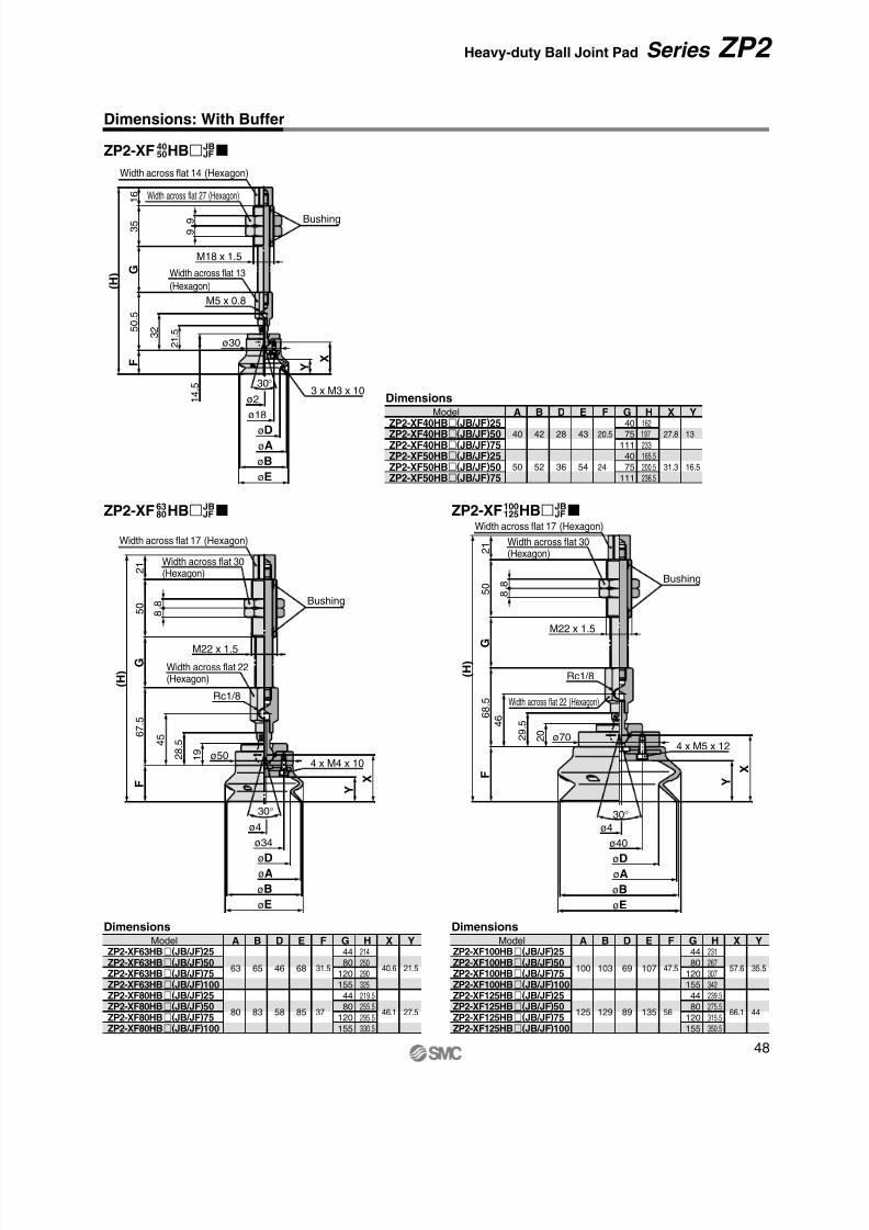
8/12/2019 Ventosa Especial Da Smc
http://slidepdf.com/reader/full/ventosa-especial-da-smc 78/119

8/12/2019 Ventosa Especial Da Smc
http://slidepdf.com/reader/full/ventosa-especial-da-smc 79/119
4 0
4 x 9 .5
4 x 6
3 x 6 .5
3 x 4
1 8
4 x 8
4 x 5
3 4
1 1
. 5 3 3 . 5
3 . 5øC
øA
ø6
øB
Y
4 . 5
4 . 5
D
øC
øA
ø8
øB
2 1
7 . 5
6
5 . 5
øC
øA
ø10
øB
ø10
ø40
øC
øA
øB
øD
E Y
6
4 x ø6
4 x ø9.5
øF
ø8
ø34
øC
øA
øB
øD
Y
4 x ø5
4 x ø8
øF
G E
ø6
ø18
øC
øA
øB
øD
Y 3 . 5
3 x ø4
3 x ø6.5
øF
E
How to Order
ø40, ø50, ø63, ø80, ø100, ø125
ZP40 H NPad diameter
40506380100125
Pad diameter
ø40
ø50
ø63
ø80
ø100
ø125
Symbol
Pad material
NSUFE
Material
NBR
Silicone rubber
Urethane rubber
FKM
EPR
Symbol
Pad type
HHB
Type
Heavy-duty (Flat with rib)
Heavy-duty (Bellows)
Symbol
ZP H4050 ZP HZP H63
80100125
Model A40
50
ZP40HZP50H
B42
52
C32
42
Dimensions
Model A63
80
ZP63HZP80H
B65
82
C50
61
D14.5
16.5
Y3.5
4.5
Dimensions
Model A100
125
ZP100HZP125H
B103
128
C 80
104
Dimensions
A63
80
B65
83
C46
58
D68
85
E31.5
37
F50
64
G4.5
5
Y21.5
27.5
Dimensions
Model
ZP63HBZP80HB
A100
125
B103
129
C69
89
D107
135
E47.5
56
F 80
105
Y35.5
44
Dimensions
Model
ZP100HBZP125HB
A40
50
B41
52
C28
36
D43
54
E20.5
24
F30
40.5
Y13
16.5
Model
ZP40HBZP50HB
Dimensions
ZP HB4050 ZP HBZP HB6380 100125
Reinforced pad preventsdeformation whentransferring heavy or largework pieces.
Heavy-duty Pad H: Heavy-duty(Flat with rib)
HB: Heavy-duty(Bellows)Pad diameter
Symbol/Type
Pad unit
Dimensions: Pad Unit
49

8/12/2019 Ventosa Especial Da Smc
http://slidepdf.com/reader/full/ventosa-especial-da-smc 80/119
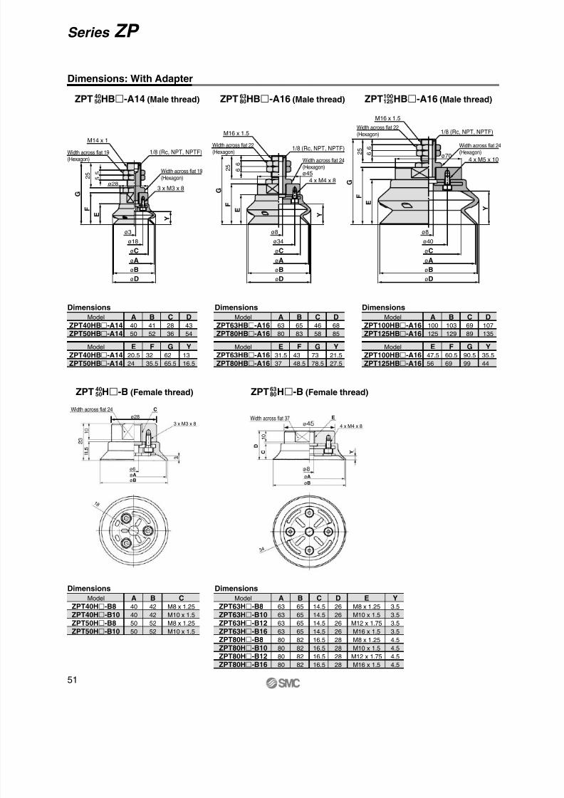
8/12/2019 Ventosa Especial Da Smc
http://slidepdf.com/reader/full/ventosa-especial-da-smc 81/119
ø8
ø34
øC
øA
øB
øD
E F
G
2 5 6
6
Y
Width across flat 22(Hexagon)
1/8 (Rc, NPT, NPTF)
4 x M4 x 8
Width across flat 24(Hexagon)
M16 x 1.5
ø45
E F
G
2 5 6
6
ø8
ø40
øC
øA
øB
øD
Y
Width across flat 22(Hexagon) 1/8 (Rc, NPT, NPTF)
M16 x 1.5
4 x M5 x 10
Width across flat 24(Hexagon)
ø70Width across flat 19(Hexagon)
1/8 (Rc, NPT, NPTF)
3 x M3 x 8
M14 x 1
Width across flat 19(Hexagon)
ø3
ø28
ø18
øC
øA
øB
øD
E F
G
2 5 5
5
Y
ø28
1 8
øA
ø6
øB
3 x M3 x 8
3 4
4 x M4 x 8
1 0
Dimensions: With Adapter
Width across flat 37
Width across flat 24
øA
øB
Dimensions
A100
125
B103
129
C69
89
D107
135
Model
ZPT100HB-A16ZPT125HB-A16
E47.5
56
F60.5
69
G90.5
99
Y35.5
44
Model
ZPT100HB-A16ZPT125HB-A16
Dimensions
A40
50
B41
52
C28
36
D43
54
Model
ZPT40HB-A14ZPT50HB-A14
E20.5
24
F32
35.5
G62
65.5
Y13
16.5
Model
ZPT40HB-A14ZPT50HB-A14
Dimensions
A63
80
B65
83
C46
58
D68
85
Model
ZPT63HB-A16ZPT80HB-A16
E31.5
37
F43
48.5
G73
78.5
Y21.5
27.5
Model
ZPT63HB-A16ZPT80HB-A16
Dimensions
Model A40
40
5050
ZPT40H-B8ZPT40H-B10
ZPT50H-B8ZPT50H-B10
B42
42
5252
CM8 x 1.25
M10 x 1.5
M8 x 1.25M10 x 1.5
Dimensions
Model A63
63
6363
80
80
80
80
ZPT63H-B8ZPT63H-B10
ZPT63H-B12ZPT63H-B16ZPT80H-B8ZPT80H-B10ZPT80H-B12ZPT80H-B16
B65
65
6565
82
82
82
82
C14.5
14.5
14.514.5
16.5
16.5
16.5
16.5
D26
26
2626
28
28
28
28
EM8 x 1.25
M10 x 1.5
M12 x 1.75M16 x 1.5
M8 x 1.25
M10 x 1.5
M12 x 1.75
M16 x 1.5
Y3.5
3.5
3.53.5
4.5
4.5
4.5
4.5
ZPT HB-A14 (Male thread)4050
ZPT H-B (Female thread)4050 ZPT H-B (Female thread)63
80
ZPT HB-A16 (Male thread)6380 ZPT HB-A16 (Male thread)100
125
51
Series ZP
C
E
Y
D
C

8/12/2019 Ventosa Especial Da Smc
http://slidepdf.com/reader/full/ventosa-especial-da-smc 82/119
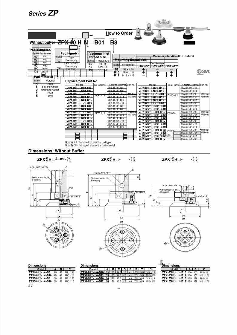
8/12/2019 Ventosa Especial Da Smc
http://slidepdf.com/reader/full/ventosa-especial-da-smc 83/119
3 x M3 x 8
1/8 (Rc, NPT, NPTF)
Width across flat 21(Hexagon)
ø70
ø
øA
øBøA
øB
4 x M5 x 10
1/8 (Rc, NPT, NPTF)
Width across flat 21(Hexagon)
Dimensions: Without Buffer
ø45
ø
øA
øB
4 x M4 x 8
1/8 (Rc, NPT, NPTF)
Width across flat 21(Hexagon)
F
E
D
C Y
G
C
C
How to Order
B8HZPX B0140 NWithout buffer
Pad diameter
40506380
100125
Pad diameter
ø40
ø50
ø63
ø80
ø100
ø125
Symbol Vacuum inletthread size
B01N01T01
Thread size
Rc1/8
NPT1/8
NPTF1/8
Symbol Mounting thread size
B8B10B12
Thread size
M8 x 1.25
M10 x 1.5
M12 x 1.75
Symbol
—
—
—
Pad diameter
ø40, ø50 ø63, ø80 ø100, ø125
H
HB
Type
Heavy-duty(Flat with rib)
Heavy-duty(Bellows)
Symbol
Model A40
40
50
50
ZPX40H- -B8ZPX40H- -B10ZPX50H- -B8ZPX50H- -B10
B42
42
52
52
CM8 x 1.25
M10 x 1.5
M8 x 1.25
M10 x 1.5
Model A63
63
80
80
ZPX63H- -B10ZPX63H- -B12ZPX80H- -B10ZPX80H- -B12
B65
65
82
82
C14.5
14.5
16.5
16.5
F63
63
65
65
D26
26
28
28
E41
41
43
43
Y3.5
3.5
4.5
4.5
GM10 x 1.5M12 x 1.75
M10 x 1.5M12 x 1.75
Model A100
100
125
125
ZPX100H- -B10ZPX100H- -B12ZPX125H- -B10ZPX125H- -B12
B103
103
128
128
CM10 x 1.5M12 x 1.75
M10 x 1.5M12 x 1.75
01
01
01
01
01
01
01
01
01
01
01
01
Dimensions Dimensions Dimensions
ZPX H- -4050
B8B1001 ZPX H- -63
80B10B1201 ZPX H- -100
125B10B1201
ZPX40∗-B01-B8ZPX40∗-N01-B8ZPX40∗-T01-B8ZPX40∗-B01-B10ZPX40∗-N01-B10ZPX40
∗-T01-B10
ZPX50∗-B01-B8ZPX50∗-N01-B8ZPX50∗-T01-B8ZPX50∗-B01-B10ZPX50∗-N01-B10ZPX50∗-T01-B10ZPX63∗-B01-B10ZPX63∗-N01-B10ZPX63∗-T01-B10ZPX63∗-B01-B12ZPX63∗-N01-B12ZPX63∗-T01-B12
ZP40∗
ZP50∗
ZP63∗
ZPA-X1-B01-B8
ZPA-X1-N01-B8
ZPA-X1-T01-B8
ZPA-X1-B01-B10
ZPA-X1-N01-B10
ZPA-X1-T01-B10
ZPA-X1-B01-B8
ZPA-X1-N01-B8
ZPA-X1-T01-B8
ZPA-X1-B01-B10
ZPA-X1-N01-B10
ZPA-X1-T01-B10
ZPA-X2-B01-B10
ZPA-X2-N01-B10
ZPA-X2-T01-B10
ZPA-X2-B01-B12
ZPA-X2-N01-B12
ZPA-X2-T01-B12
With threeM3 bolts
With threeM3 bolts
With fourM4 bolts
Model Pad unit part no. Adapter assembly part no.
Note 1) ∗ in the table indicates the pad type.Note 2) in the table indicates the pad material.
Replacement Part No.
ZPX80∗-B01-B10ZPX80∗-N01-B10ZPX80∗-T01-B10ZPX80∗-B01-B12ZPX80∗-N01-B12ZPX80
∗-T01-B12
ZPX100∗-B01-B10ZPX100∗-N01-B10ZPX100∗-T01-B10ZPX100∗-B01-B12ZPX100∗-N01-B12ZPX100∗-T01-B12ZPX125∗-B01-B10ZPX125∗-N01-B10ZPX125∗-T01-B10ZPX125∗-B01-B12ZPX125∗-N01-B12ZPX125∗-T01-B12
ZP80∗
ZP100∗
ZP125∗
ZPA-X2-B01-B10
ZPA-X2-N01-B10
ZPA-X2-T01-B10
ZPA-X2-B01-B12
ZPA-X2-N01-B12
ZPA-X2-T01-B12
ZPA-X3-B01-B10
ZPA-X3-N01-B10
ZPA-X3-T01-B10
ZPA-X3-B01-B12
ZPA-X3-N01-B12
ZPA-X3-T01-B12
ZPA-X3-B01-B10
ZPA-X3-N01-B10
ZPA-X3-T01-B10
ZPA-X3-B01-B12
ZPA-X3-N01-B12
ZPA-X3-T01-B12
With fourM4 bolts
With fourM5 bolts
With fourM5 bolts
Model Pad unit part no. Adapter assembly part no.
Pad material ()
NSUFE
Material
NBR
Silicone rubber
Urethane rubber
FKM
EPR
Symbol
Vacuum inlet direction LateralPad type ( )
53
Series ZP

8/12/2019 Ventosa Especial Da Smc
http://slidepdf.com/reader/full/ventosa-especial-da-smc 84/119
Width across flat 21(Hexagon)
1/8 (Rc, NPT, NPTF)
4 x M5 x 10
I
ø4
ø40
øC
øA
øB
øD
Y E
F
G
H
1 1
ø70
Width across flat 21(Hexagon)
1/8 (Rc, NPT, NPTF)
3 x M3 x 8
I
E F
G
H
ø3
ø18
øC
øA
øB
øD
Y
1 1
ø28
Width across flat 21(Hexagon)
1/8 (Rc, NPT, NPTF)
4 x M4 x 8
I
ø4
ø34
øC
øA
øB
øD
Y E
F
G
H
1 1
ø45
ZPX HB- -4050
B8B1001 ZPX HB- -63
80B10B1201 ZPX HB- -100
125B10B1201
Dimensions: Without Buffer
Model A
40
50
B
41
52
C
28
36
D
43
54
E
20.5
24
F
32
35.5
ZPX40HB- -B8ZPX40HB- -B10ZPX50HB- -B8ZPX50HB- -B10
Dimensions
01
01
01
01
Model
ZPX40HB- -B8ZPX40HB- -B10ZPX50HB- -B8ZPX50HB- -B10
01
01
01
01
G
47
50.5
H
69
72.5
I
M8 x 1.25M10 x 1.5
M8 x 1.25
M10 x 1.5
Y
13
16.5
Model A
63
80
B
65
83
C
46
58
D
68
85
E
31.5
37
F
43
48.5
ZPX63HB- -B10ZPX63HB- -B12ZPX80HB- -B10ZPX80HB- -B12
Dimensions
01
01
Model
ZPX63HB- -B10ZPX63HB- -B12ZPX80HB- -B10ZPX80HB- -B12
01
01
01
01
01
01
G
58
63.5
H
80
85.5
I
M10 x 1.5M12 x 1.75
M10 x 1.5
M12 x 1.75
Y
21.5
27.5
Model A
100
125
B
103
129
C
69
89
D
107
135
E
47.5
56
F
60.5
69
ZPX100HB- -B10ZPX100HB- -B12ZPX125HB- -B10ZPX125HB- -B12
Dimensions
01
01
Model
ZPX100HB- -B10ZPX100HB- -B12ZPX125HB- -B10ZPX125HB- -B12
01
01
01
01
01
01
G
75.5
84
H
97.5
106
I
M10 x 1.5M12 x 1.75
M10 x 1.5
M12 x 1.75
Y
35.5
44
54
Series ZP Heavy-duty Pad

8/12/2019 Ventosa Especial Da Smc
http://slidepdf.com/reader/full/ventosa-especial-da-smc 85/119
3 x M3 x 8
1/8 (Rc, NPT, NPTF)Width across flat 14 (Hexagon)
2 0 . 5 Width across flat 27
(Hexagon)
4 x M4 x 8
1/8 (Rc, NPT, NPTF)
Width across flat 14
(Hexagon)
Width across flat 27
(Hexagon) 2 0 . 5
4 x M5 x 10
1/8 (Rc, NPT, NPTF)Width across flat 17
(Hexagon)
Width across flat 30 (Hexagon) 2 4
25
Model A40
40
40
50
50
50
ZPT40H 25- -A18ZPT40H 50- -A18ZPT40H 75- -A18ZPT50H 25- -A18ZPT50H 50- -A18ZPT50H 75- -A18
B42
42
42
52
52
52
C 63
98
134
63
98
134
D118.5
153.5189.5118.5
153.5189.5
Model A63
63
63
80
80
80
ZPT63H 25- -A18ZPT63H 50- -A18ZPT63H 75- -A18ZPT80H 25- -A18ZPT80H 50- -A18ZPT80H 75- -A18
B65
65
65
82
82
82
C14.514.514.516.516.516.5
F121.5
156.5192.5123.5
158.5194.5
D26
26
26
28
28
28
E 66
101
137
68
103
139
Y3.5
3.5
3.5
4.5
4.5
4.5
Model A100
100
100
100
125
125
125
125
ZPT100H 25- -A22ZPT100H 50- -A22ZPT100H 75- -A22ZPT100H 100- -A22ZPT125H 25- -A22ZPT125H 50- -A22ZPT125H 75- -A22ZPT125H 100- -A22
B103
103
103
103
128
128
128
128
C 78
114
154
189
78
114
154
189
D152
188
228
263
152
188
228
263
With buffer ZPT A18B0140 H N JPad diameter
40506380
100125
Pad diameterø40
ø50
ø63
ø80
ø100
ø125
Symbol
Buffer body
material ( )
JJBJF
Material
Aluminum alloy
Brass + With bushing
Steel + With bushing
Symbol
255075
100
ø40
—
ø50
—
ø63
—
ø80
—
ø100
ø125
Stroke
Buffer stroke ()
Vacuum inletthread size
B01N01T01
Thread size
Rc1/8
NPT1/8
NPTF1/8
Symbol
Mounting thread size
A18A22
Thread size
M18 x 1.5 (ø40 to ø80)
M22 x 1.5 (ø100, ø125)
Symbol
H
HB
Type
Heavy-duty(Flat with rib)
Heavy-duty(Bellows)
Symbol
Buffer Specifications (Rotating)
Pad diameter ø40 to ø80
6.9 N
11.8 N
At 0 stroke
At Full stroke
Stroke (mm)
Springreactiveforce
ø100, ø125
10 N
15 N
25, 50, 75 25, 50, 75, 100
01
01
01
01
01
01
01
01
01
01
01
01
01
01
01
01
01
01
01
01
Dimensions Dimensions Dimensions
Tightening Torque
Aluminumalloy
Brass+
With bushing
Steel+
With bushing
Buffer bodymaterialMounting
thread size
9.5 to 10.5 N·m
9.5 to 10.5 N·m
28 to 32 N·m
45 to 50 N·m
48 to 52 N·m
75 to 80 N·m
M18 x 1.5
M22 x 1.5
(N·m)
∗ Control value shall be ±5% of the tightening torque.
Replacement Part No.
ZPT40∗ 25-(B/N/T)01-A18ZPT40∗ 50-(B/N/T)01-A18
ZPT40∗ 75-(B/N/T)01-A18ZPT50∗ 25-(B/N/T)01-A18ZPT50∗ 50-(B/N/T)01-A18ZPT50∗ 75-(B/N/T)01-A18ZPT63∗ 25-(B/N/T)01-A18ZPT63∗ 50-(B/N/T)01-A18ZPT63∗ 75-(B/N/T)01-A18ZPT80∗ 25-(B/N/T)01-A18ZPT80∗ 50-(B/N/T)01-A18ZPT80∗ 75-(B/N/T)01-A18ZPT100∗ 25-(B/N/T)01-A22ZPT100∗ 50-(B/N/T)01-A22ZPT100∗ 75-(B/N/T)01-A22ZPT100∗ 100-(B/N/T)01-A22ZPT125∗ 25-(B/N/T)01-A22ZPT125∗ 50-(B/N/T)01-A22ZPT125∗ 75-(B/N/T)01-A22ZPT125∗ 100-(B/N/T)01-A22
ZP40∗
ZP50∗
ZP63∗
ZP80∗
ZP100∗
ZP125∗
ZPB-T1 25-(B/N/T)01
ZPB-T1 50-(B/N/T)01
ZPB-T1 75-(B/N/T)01ZPB-T1 25-(B/N/T)01
ZPB-T1 50-(B/N/T)01
ZPB-T1 75-(B/N/T)01
ZPB-T2 25-(B/N/T)01
ZPB-T2 50-(B/N/T)01
ZPB-T2 75-(B/N/T)01
ZPB-T2 25-(B/N/T)01
ZPB-T2 50-(B/N/T)01
ZPB-T2 75-(B/N/T)01
ZPB-T3 25-(B/N/T)01
ZPB-T3 50-(B/N/T)01
ZPB-T3 75-(B/N/T)01
ZPB-T3 100-(B/N/T)01
ZPB-T3 25-(B/N/T)01
ZPB-T3 50-(B/N/T)01
ZPB-T3 75-(B/N/T)01
ZPB-T3 100-(B/N/T)01
With threeM3 bolts
With fourM4 bolts
With fourM5 bolts
Model Pad unit part no. Buffer assembly part no.
Note 1) ∗ in the table indicates the pad type.
Note 2) in the table indicates the pad material.
Note 3) in the table indicates the buffer body material.
How to Order
Pad material ()
NSUFE
Material
NBR
Silicone rubber
Urethane rubber
FKM
EPR
Symbol
Vacuum inlet direction Vertical
Dimensions: With Buffer
4050 01ZPT H - -A18 01ZPT H - -A1863
80 01ZPT H - -A22100125
Pad type ( )
( D )
E
D
C
Y
( F )
C
øAøB
( D
)
C
øA
øB
øA
øB
55
Series ZP

8/12/2019 Ventosa Especial Da Smc
http://slidepdf.com/reader/full/ventosa-especial-da-smc 86/119
Width across flat 14(Hexagon)
M18 x 1.5
Width across flat 27
(Hexagon)
1/8 (Rc, NPT, NPTF)
4 x M4 x 8
ø3ø34
øC
øA
øB
øD
Y E
F
G
( H )
3 5
9
9
ø45
E F
G
( H )
5 0
2
4
8
8
ø4ø40
øC
øA
øB
øD
Y
Width across flat 17 (Hexagon)
M22 x 1.5Width across flat 30 (Hexagon)
1/8 (Rc, NPT, NPTF)
4 x M5 x 10
ø70
2 0
. 5
Width across flat 14(Hexagon)
M18 x 1.5
Width across flat 27
(Hexagon)
3 x M3 x 8
ø3ø18
øC
øA
øB
øD
Y E F
G
( H )
3 5
2 0
. 5
9
9
ø28
1/8 (Rc, NPT, NPTF)
4050 01ZPT HB - -A18 01ZPT HB - -A1863
80 01ZPT HB - -A22100125
Model A
100
125
B
103
129
C
69
89
D
107
135
E
47.5
56
Dimensions
ZPT100HB 25- -A22ZPT100HB 50- -A22ZPT100HB 75- -A22ZPT100HB 100- -A22ZPT125HB 25- -A22ZPT125HB 50- -A22ZPT125HB 75- -A22ZPT125HB 100- -A22
01
01
01
01
01
01
01
01
Model A
63
80
B
65
83
C
46
58
D
68
85
E
31.5
37
Dimensions
ZPT63HB 25- -A18ZPT63HB 50- -A18ZPT63HB 75- -A18ZPT80HB 25- -A18ZPT80HB 50- -A18ZPT80HB 75- -A18
01
01
01
01
01
01
Model A
40
50
B
41
52
C
28
36
D
43
54
E
20.5
24
ZPT40HB 25- -A18ZPT40HB 50- -A18ZPT40HB 75- -A18ZPT50HB 25- -A18ZPT50HB 50- -A18ZPT50HB 75- -A18
01
01
01
01
01
01
Dimensions
Model G104.5
140.5180.5215.5
113149
189224
F
60.5
69
H178.5
214.5254.5289.5
187223
263298
Y
35.5
44
ZPT100HB 25- -A22ZPT100HB 50- -A22ZPT100HB 75- -A22ZPT100HB 100- -A22ZPT125HB 25- -A22ZPT125HB 50- -A22ZPT125HB 75- -A22ZPT125HB 100- -A22
01
01
01
01
01
01
01
01
Model F
43
48.5
G83
118154
88.5123.5159.5
H138.5
173.5209.5
144179215
Y
21.5
27.5
ZPT63HB 25- -A18ZPT63HB 50- -A18ZPT63HB 75- -A18ZPT80HB 25- -A18ZPT80HB 50- -A18ZPT80HB 75- -A18
01
01
01
01
01
01
Model F
32
35.5
G72
107143
75.5110.5146.5
H127.5
162.5198.5
131166202
Y
13
16.5
ZPT40HB 25- -A18ZPT40HB 50- -A18ZPT40HB 75- -A18ZPT50HB 25- -A18ZPT50HB 50- -A18ZPT50HB 75- -A18
01
01
01
01
01
01
56
Series ZP Heavy-duty Pad
Dimensions: With Buffer

8/12/2019 Ventosa Especial Da Smc
http://slidepdf.com/reader/full/ventosa-especial-da-smc 87/119

8/12/2019 Ventosa Especial Da Smc
http://slidepdf.com/reader/full/ventosa-especial-da-smc 88/119

8/12/2019 Ventosa Especial Da Smc
http://slidepdf.com/reader/full/ventosa-especial-da-smc 89/119
(ø28.5)
4 x ø7
2 0
P C D 2 2
. 5
0 . 5
1 6. 5
4 x 1
2 0
2 5
2 8 .5
Ring-shaped adsorption area
ZPT1-A5 is a recommended adapter.
(Four adapters are necessary.)
See below for mounting.
Refer to the Best Pneumatics No. 4 for details.
Example of attachment
Vacuum Pad for Transferring Disks
Dimensions
For adsorbing and transferring disks ofdigital household electric appliances(CD, DVD)• For adsorbing circular components like CD and
DVD
• Bellows mechanism is realized in the pad todampen the impact to the work.
How to Order
ZP2 Z1 S001
Pad material
SGS
Material
Silicone rubber
Urethane rubber
Symbol
ZP2-Z1-001-
Vac. Vac. Vac. ZPT1-A54 x M5 x 0.8
P C D 2
2. 5
59

8/12/2019 Ventosa Especial Da Smc
http://slidepdf.com/reader/full/ventosa-especial-da-smc 90/119
A
A
4 0
40
4 0
A
A
20 –0.1–0.2
2 0
– 0 . 1
– 0 . 2
2 0
A-A
4
ø9
ø11
1 . 5 ø5 (∗)
4 x ø490°
4 x ø2.4
wq
e
0 . 9
ø9.4
A-A
5
1 . 5
ø20
ø18
ø12 (∗) 4 x ø2.4
4 x ø4
90°
q w
1 . 8
ø18.4
e
Dimensions
ZP2-Z002 ZP2-Z003
Component Parts
Part no. DescriptionNo.
ZP2-Z2A
ZP2-Z2B
ZP2-Z2C
Pad
Joint
Mounting plate
Material
PTFE
FKM
Aluminum alloy
Note
—
—
Clear anodized
1
2
3
Component Parts
Part no. DescriptionNo.
ZP2-Z3A
ZP2-Z3B
ZP2-Z3C
Pad
Joint
Mounting plate
Material
PTFE
FKM
Aluminum alloy
Note
—
—
Clear anodized
1
2
3
Vacuum Pad for Fixing Panel
For adsorbing and fixing the stage of LCD panels, etc.
Bellows mechanism allows complete contact with curved work surface.
The plate for air purging should be prepared by the customer.
The plate needs to have supporting points.
(Avoid applying the weight of the workpiece directly to the pad.)
Place the workpiece on the pad horizontally.
How to use
Vacuum
WorkpieceMounting plate
When a hole is made in the plate, the dimension shall be (∗) or less.
Supporting point
60
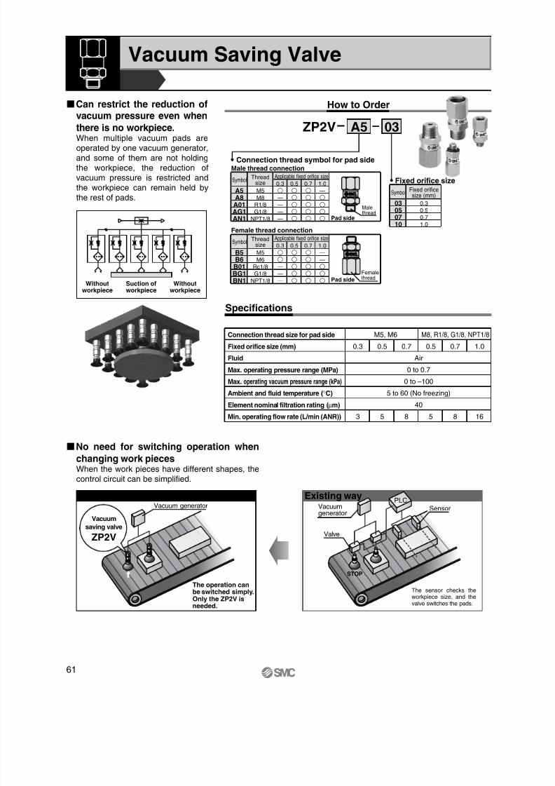
8/12/2019 Ventosa Especial Da Smc
http://slidepdf.com/reader/full/ventosa-especial-da-smc 91/119
How to Order
Suction ofworkpiece
Withoutworkpiece
Withoutworkpiece
03
Fixed orificesize (mm)
0.3
0.5
0.7
1.0
Symbol
03050710
Fixed orifice size
A5
Connection thread symbol for pad side
Applicable fixed orifice size
M5
M8
R1/8
G1/8
NPT1/8
0.3
—
—
—
—
0.5
0.7
1.0
—
SymbolThread
size
A5A8A01AG1AN1
Male thread connection
Applicable fixed orifice size
M5
M6
Rc1/8
G1/8
NPT1/8
0.3—
—
—
0.5
0.7
1.0—
—
Symbol
Thread
sizeB5B6B01BG1BN1
Female thread connection
Pad side
Femalethread
Malethread
Pad side
No.0.8
No.0.8
Vacuum Saving Valve
ZP2V
Can restrict the reduction ofvacuum pressure even when
there is no workpiece.When multiple vacuum pads areoperated by one vacuum generator,and some of them are not holdingthe workpiece, the reduction ofvacuum pressure is restricted andthe workpiece can remain held bythe rest of pads.
No need for switching operation when
changing work piecesWhen the work pieces have different shapes, thecontrol circuit can be simplified.
Connection thread size for pad side
Fixed orifice size (mm)
Fluid
Max. operating pressure range (MPa)
Max. operating vacuum pressure range (kPa)
Ambient and fluid temperature (°C)
Element nominal filtration rating (µm)
Min. operating flow rate (L/min (ANR))
M5, M6 M8, R1/8, G1/8, NPT1/8
0.3 0.5 0.7
Air
0 to 0.7
0 to –100
5 to 60 (No freezing)
40
0.5 0.7 1.0
3 5 8 5 8 16
Use of ZP2V Existing way
Valve
The operation canbe switched simply.Only the ZP2V isneeded.
PLCVacuumgenerator
Vacuum generator
STOP
Sensor
The sensor checks theworkpiece size, and thevalve switches the pads.
ZP2V
Vacuum
saving valve
Specifications
61
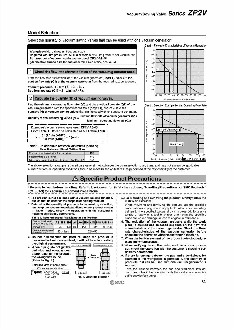
8/12/2019 Ventosa Especial Da Smc
http://slidepdf.com/reader/full/ventosa-especial-da-smc 92/119
Chart 1. Flow-rate Characteristics of Vacuum Generator
–100
–90
–80
–70
–60
–50
–40
–30
–20
–10
00 10 20 30 40 50 60 70 80 90 100 110
Suction flow rate (L/min (ANR))
V a c u u m
p r e s s u r e
( k P a
)
Connection thread size for pad sideFixed orifice size (mm)
Minimum operating flow rate (L/min (ANR)) Q2
M80.5
5.0
Table 1. Relationship between Minimum OperatingFlow Rate and Fixed Orifice Size
Connection threadsymbol for pad side
Thread size
Recommended paddiameter (mm)
A5 B5 B6 A8 A01 B01 AG1BG1 AN1 BN1
M5
25 or less 32 to 50
M6 M8 R1/8 G1/8 NPT1/8
Table 1. Recommended Pad Diameter per Product
Vacuum generator side
Name
plate
Fig. 1. Mounting direction
Pad side
Vacuum generator side
Pad side
(Vacuum generator side)
(Pad side)
Enlarged view of name plate
No.0.8
ZP2V-A5-03 G MPMADE IN JAPAN
N = 6 (unit)
Q1 = 31 L/min (ANR)
Q2 = 5.0 L/min (ANR)
–100
–90
–80
–70
–60
–50
–40
–30
–20
–100 5 10 15 20 25 30 35
Suction flow rate (L/min (ANR))
V a c u u m
p r e s s u r e
( k P a
)
Chart 2. Selection Example by Min. Operating Flow Rate
q w
e
Example) Vacuum saving valve used: ZP2V-A8-05
From Table 1, Q2 can be calculated as 5.0 L/min (ANR).
N = ≈ 6 (unit)31 L/min (ANR)
5 L/min (ANR)
Select the quantity of vacuum saving valves that can be used with one vacuum generator.
Selection Conditions
Workpiece: No leakage and several sizesRequired vacuum pressure: –50 kPa or moreof vacuum pressure per vacuum pad Part number of vacuum saving valve used: ZP2V-A8-05(Connection thread size for pad side: M8, Fixed orifice size: ø0.5)
The above selection example is based on a general method under the given selection conditions, and may not always be applicable.
A final decision on operating conditions should be made based on test results performed at the responsibility of the customer.
Model Selection
Find the minimum operating flow rate (Q2) and the suction flow rate (Q1) of the
vacuum generator from the specifications table (page 61), and calculate the
quantity (N) of vacuum saving valves that can be used with one vacuum generator.
Check the flow-rate characteristics of the vacuum generator used.1
2 Calculate the quantity (N) of vacuum saving valves.
From the flow-rate characteristics of the vacuum generator (Chart 1), calculate the
suction flow rate (Q1) of the vacuum generator from the required vacuum pressure.
Vacuum pressure –50 kPa (q→w→e) =
Suction flow rate (Q1) ≈ 31 L/min (ANR).
Specific Product Precautions
Be sure to read before handling. Refer to back cover for Safety Instructions, “Handling Precautions for SMC Products”
(M-E03-3) for Vacuum Equipment Precautions.
1. The product is not equipped with a vacuum holding function,and cannot be used for the purpose of holding vacuum.
2. Determine the quantity of products to be used by selection,and keep the recommended pad diameter per product shownin Table 1. Also, check the operation with the customer’smachine sufficiently beforehand.
3. Do not disassemble the product. Once the product isdisassembled and reassembled, it will not be able to satisfythe original performance.
4. When piping, do not get thepad side and vacuum gen-erator side of the product
the wrong way round.(Refer to Fig. 1.)
5. For mounting and removing the product, strictly follow theinstructions below.
When mounting and removing the product, use the specifiedplaces shown in page 64 to apply tools. Also, when mounting,tighten to the specified torque shown in page 64. Excessivetorque or applying a tool to places other than the specifiedplace can cause damage or loss of original performance.
6. The reduction of the vacuum pressure while the workpiece is sucked and released depends on the flow-ratecharacteristics of the vacuum generator. Check the flow-rate characteristics of the vacuum generator beforechecking the operation with the customer’s machine.
7. When the built-in element of the product gets clogged, re-place the whole product.
8. When verifying the suction using such as a pressure sen-sor, check the operation with the customer’s machine suf-ficiently beforehand.
9. If there is leakage between the pad and a workpiece, forexample if the workpiece is permeable, the quantity ofproducts that can be used with one vacuum generator isreduced.
Take the leakage between the pad and workpiece into ac-count and check the operation with the customer’s machinesufficiently before using.
Suction flow rate of vacuum generator (Q1)
Minimum operating flow rate (Q2)Quantity of vacuum saving valves (N) =
62
Series ZP2V Vacuum Saving Valve

8/12/2019 Ventosa Especial Da Smc
http://slidepdf.com/reader/full/ventosa-especial-da-smc 93/119
ZP2V-A- ZP2V-B-
q
w
e
r
t
y
u
u
No.0.8
Construction
When a workpiece is suckedInitial condition
Without workpiece With workpiece
When a workpiece isreleased
Valve
Spring
Element
Fixed orifice size
Element
Closed valve Opened valve Opened valve
Workpiece
Vacuumair
Vacuumair
Breakingair
Since there is no air flow, the valveremains opened by the spring force.
When the workpiece is separatedfrom the vacuum pad, the valve isclosed by the air flow, and the suc-tion air can only flow through thefixed orifice. At this time, an amountof air corresponding to the fixed ori-fice size is sucked.
When the workpiece is sucked bythe vacuum pad, the suction flow re-duces, and the valve is opened bythe spring force, which opens thepath between the valve and body forsuction.
When the workpiece is released,the valve is opened by the vacuumbreaking air, and the path betweenthe valve and body will open.
V a l v e o
p e r a t i n g c o n d i t i o n
A i r f l o w
No.
1
23
4
5
6
7
Body A
Body BValve
O-ring
Spring
Element
Gasket
Description
Component Parts
Material
Brass
BrassAluminum
HNBR
Stainless steel
BC
NBR + Stainless steel
Surface treatment
Electroless nickel plated
Electroless nickel plated—
—
—
—
—
Vacuum generator side Vacuum generator side
Pad side
Pad side
∗ For the mounting direction of theproduct, refer to 4 on page 62.
63
Series ZP2V
Working Principle

8/12/2019 Ventosa Especial Da Smc
http://slidepdf.com/reader/full/ventosa-especial-da-smc 94/119
M1 M1
M2M2
H∗2
H∗1
H∗1 H∗1
H∗1
H∗1
H∗1
H∗2H∗2
H∗2
H∗2
H∗2
M2
M1
( L 4 )
L 1
L 2
L 3 ∗ 3
( L 4 )
L 1
M2
L 1
L 3
L 2
( L 4 )
M2
L 2
( L 4 )
M1
M2
M1
L 1
L 2
L 3 ∗ 3
( L 4 )
M1
L 2
L 1
L 3
( L 4 )
L 1
L 3
L 2
L 3
øD
øD
No.0.8
No.0.8
No.0.8
No.0.8 No.0.8
No.0.8
Vacuum generator side
Pad side
Vacuum generator side
Pad side
Vacuum generator side
Vacuum generator side
Vacuum generator side
Vacuum generator side
Pad side
Pad sidePad side Pad side
ZP2V-A5-ZP2V-A8-
ZP2V-B5-ZP2V-B6-
ZP2V-A01-ZP2V-AN1-
ZP2V-AG1-
ZP2V-B01-ZP2V-BN1-
ZP2V-BG1-
Model M1 M2 L1 L2 L3 L4H
(Width across flat) øDW(g)
ZP2V-A5-ZP2V-A8-ZP2V-A01-ZP2V-AG1-ZP2V-AN1-ZP2V-B5-
ZP2V-B6-ZP2V-B01-ZP2V-BG1-ZP2V-BN1-
M5 x 0.8
M8 x 1.25
R1/8
G1/8
NPT1/8
M5 x 0.8
M6 x 1
Rc1/8
G1/8
NPT1/8
M5 x 0.8
M8 x 1.25
Rc1/8
G1/8
NPT1/8
M5 x 0.8
M6 x 1
R1/8
G1/8
NPT1/8
3.4
5.9
3.1
5.1
3.2
5.5
5
6.2
8
6.9
4.5
8
6.2
8
6.9
3.4
4.5
3.1
5.1
3.2
14.7
20.1
22.6
22.5
23.3
16.6
16.2
23.5
23.4
24.2
18.1
26
25.7
27.6
26.5
20
20.7
26.6
28.5
27.4
8
12
12
13
12
8
8
12
13
12
—
—
—
14
—
—
—
—
14
—
6
18
18
23
23
7
7
19
24
20
Tightening torque(N·m) Note)
1.0 to 1.5
5.5 to 6.0
7.0 to 9.0
5.5 to 6.0
7.0 to 9.0
1.0 to 1.5
2.0 to 2.5
7.0 to 9.0
5.5 to 6.0
7.0 to 9.0
(mm)
Dimensions
∗1 The place at the vacuum generator side where the tool is applied.
∗2 The place at the pad side where the tool is applied.
∗3 Referential dimensions after the R, NPT thread is screwed.
Note) When mounting and removing the product, apply a wrench or torque wrench to the place shown in Figure.When mounting, tighten to the torque specified in the table.
64
Series ZP2V Vacuum Saving Valve
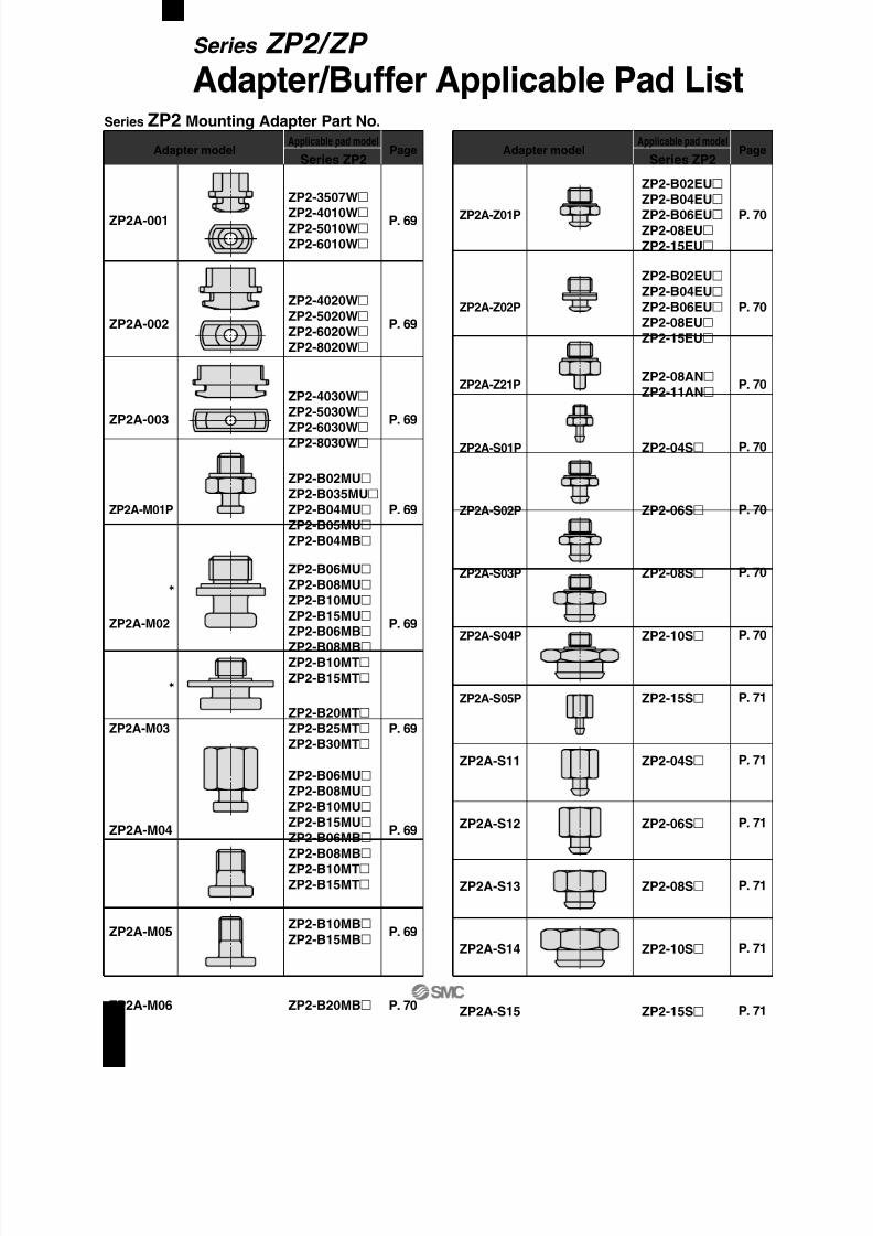
8/12/2019 Ventosa Especial Da Smc
http://slidepdf.com/reader/full/ventosa-especial-da-smc 95/119
Series ZP2 Mounting Adapter Part No.
P. 69
P. 69
P. 69
P. 69
P. 69
P. 69
P. 69
P. 69
P. 70
Adapter modelApplicable pad model
Series ZP2Page
ZP2-3507WZP2-4010WZP2-5010WZP2-6010W
ZP2-4020WZP2-5020WZP2-6020WZP2-8020W
ZP2-4030WZP2-5030WZP2-6030WZP2-8030W
ZP2-B02MUZP2-B035MUZP2-B04MUZP2-B05MUZP2-B04MB
ZP2-B06MUZP2-B08MUZP2-B10MUZP2-B15MUZP2-B06MBZP2-B08MBZP2-B10MTZP2-B15MT
ZP2-B20MTZP2-B25MTZP2-B30MT
ZP2-B06MUZP2-B08MUZP2-B10MUZP2-B15MUZP2-B06MBZP2-B08MBZP2-B10MTZP2-B15MT
ZP2-B10MBZP2-B15MB
ZP2-B20MB
ZP2A-001
ZP2A-002
ZP2A-003
ZP2A-M01P
ZP2A-M02
ZP2A-M03
ZP2A-M04
ZP2A-M05
ZP2A-M06
P. 70
P. 70
P. 70
P. 70
P. 70
P. 70
P. 70
P. 71
P. 71
P. 71
P. 71
P. 71
P. 71
Adapter modelApplicable pad model
Series ZP2Page
ZP2-B02EUZP2-B04EUZP2-B06EUZP2-08EUZP2-15EU
ZP2-B02EUZP2-B04EUZP2-B06EUZP2-08EUZP2-15EU
ZP2-08ANZP2-11AN
ZP2-04S
ZP2-06S
ZP2-08S
ZP2-10S
ZP2-15S
ZP2-04S
ZP2-06S
ZP2-08S
ZP2-10S
ZP2-15S
ZP2A-Z01P
ZP2A-Z02P
ZP2A-Z21P
ZP2A-S01P
ZP2A-S02P
ZP2A-S03P
ZP2A-S04P
ZP2A-S05P
ZP2A-S11
ZP2A-S12
ZP2A-S13
ZP2A-S14
ZP2A-S15
Series ZP2/ZP
Adapter/Buffer Applicable Pad List
65
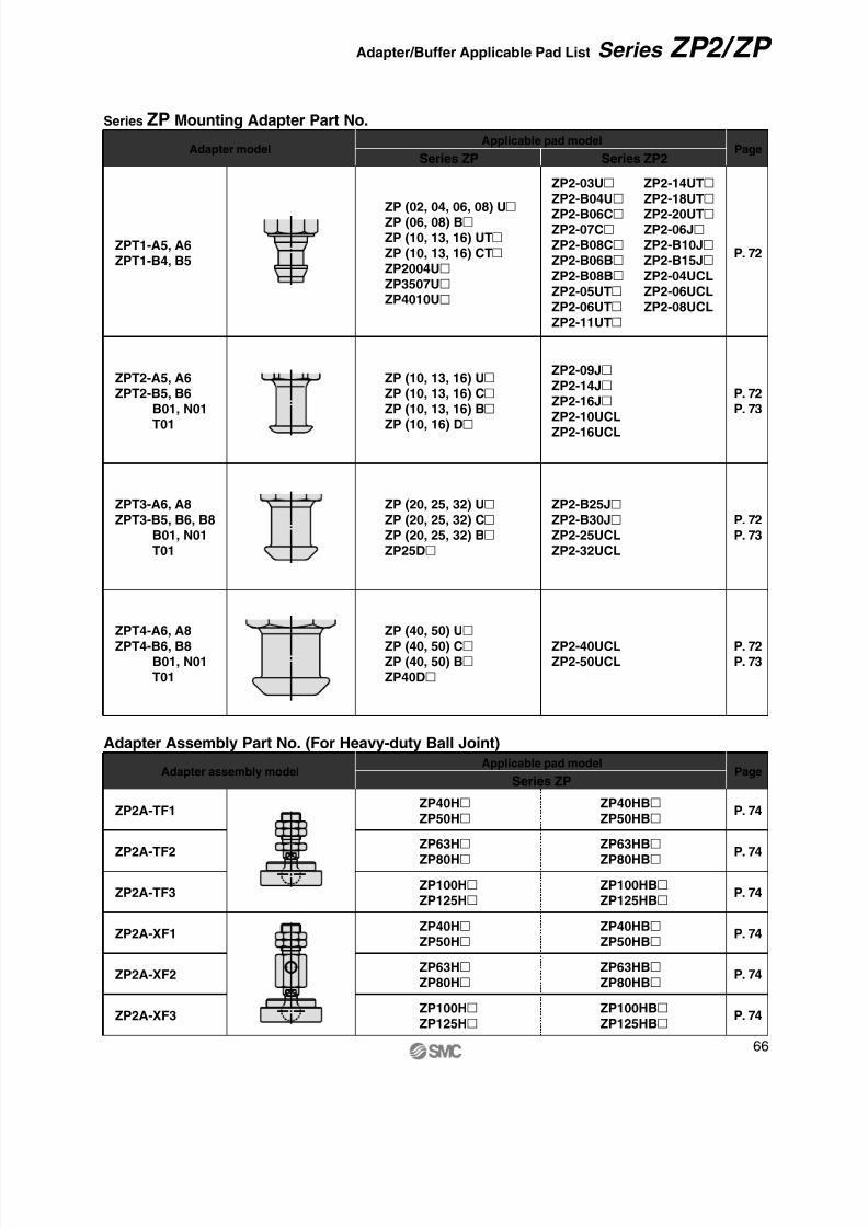
8/12/2019 Ventosa Especial Da Smc
http://slidepdf.com/reader/full/ventosa-especial-da-smc 96/119
Series ZP Mounting Adapter Part No.
Adapter modelApplicable pad model
Series ZP2Series ZPPage
Adapter Assembly Part No. (For Heavy-duty Ball Joint)
Adapter assembly model Applicable pad modelSeries ZP
Page
P. 72
P. 72P. 73
P. 72P. 73
P. 72P. 73
P. 74
P. 74
P. 74
P. 74
P. 74
P. 74
ZP2A-TF1
ZP2A-TF2
ZP2A-TF3
ZP2A-XF1
ZP2A-XF2
ZP2A-XF3
ZP40HBZP50HB
ZP40HZP50H
ZP63HBZP80HB
ZP63HZP80H
ZP100HBZP125HB
ZP100HZP125H
ZP40HBZP50HB
ZP40HZP50H
ZP63HBZP80HB
ZP63HZP80H
ZP100HBZP125HB
ZP100HZP125H
ZPT1-A5, A6ZPT1-B4, B5
ZPT2-A5, A6ZPT2-B5, B6B01, N01T01
ZPT3-A6, A8ZPT3-B5, B6, B8
B01, N01T01
ZPT4-A6, A8ZPT4-B6, B8
B01, N01T01
ZP2-03UZP2-B04UZP2-B06CZP2-07CZP2-B08CZP2-B06BZP2-B08BZP2-05UTZP2-06UTZP2-11UT
ZP2-14UTZP2-18UTZP2-20UTZP2-06JZP2-B10JZP2-B15JZP2-04UCLZP2-06UCLZP2-08UCL
ZP (02, 04, 06, 08) UZP (06, 08) BZP (10, 13, 16) UTZP (10, 13, 16) CTZP2004UZP3507UZP4010U
ZP2-09J
ZP2-14JZP2-16JZP2-10UCLZP2-16UCL
ZP (10, 13, 16) UZP (10, 13, 16) CZP (10, 13, 16) BZP (10, 16) D
ZP (20, 25, 32) UZP (20, 25, 32) CZP (20, 25, 32) BZP25D
ZP (40, 50) UZP (40, 50) CZP (40, 50) BZP40D
ZP2-B25JZP2-B30JZP2-25UCLZP2-32UCL
ZP2-40UCLZP2-50UCL
66
Series ZP2/ZP Adapter/Buffer Applicable Pad List

8/12/2019 Ventosa Especial Da Smc
http://slidepdf.com/reader/full/ventosa-especial-da-smc 97/119

8/12/2019 Ventosa Especial Da Smc
http://slidepdf.com/reader/full/ventosa-especial-da-smc 98/119
ZP40HZP50HZP40HBZP50HB
ZP63HZP80HZP63HB
ZP80HBZP100HZP125HZP100HBZP125HB
ZP40HZP50HZP40HBZP50HB
ZP63HZP80HZP63HB
ZP80HB
ZP100HZP125HZP100HBZP125HB
ZPB-T1 (J/JB/JF)- 01
ZPB-T2 (J/JB/JF)- 01
ZPB-T3 (J/JB/JF)- 01
ZPB-X1 (J/JB/JF)- 01
ZPB-X2 (J/JB/JF)- 01
ZPB-X3 (J/JB/JF)- 01
P. 80P. 81
P. 80P. 81
P. 80P. 81
P. 82P. 83
P. 82P. 83
P. 82P. 83
Buffer Assembly Part No. (for Heavy-duty)
Buffer assembly modelApplicable pad model
Series ZPPage
ZP40H
ZP50HZP40HBZP50HB
ZP63HZP80HZP63HBZP80HB
ZP40HZP50HZP40HBZP50HB
ZP63HZP80HZP63HBZP80HB
ZP100HZP125HZP100HBZP125HB
ZP100HZP125HZP100HBZP125HB
ZP2B-TF1 (JB/JF)
ZP2B-TF2 (JB/JF)
ZP2B-TF3 (JB/JF)
ZP2B-XF1 (JB/JF)
ZP2B-XF2 (JB/JF)
ZP2B-XF3 (JB/JF)
P. 78
P. 78
P. 78
P. 79
P. 79
P. 79
Buffer Assembly Part No. (for Heavy-duty Ball Joint)
Buffer assembly modelApplicable pad model
Series ZPPage
68
Series ZP2/ZP Adapter/Buffer Applicable Pad List

8/12/2019 Ventosa Especial Da Smc
http://slidepdf.com/reader/full/ventosa-especial-da-smc 99/119
Width across flat 5
(Hexagon)
M3 x 0.5
1
ø1.2
ø2
ø3
R 2
. 5
2 . 5
2 . 5
R
Width acrossflat 1.5
(Hexagon)
M5 x 0.8
ø8
ø4
ø6
2
3 . 5
ø1.5
R
R 1 .
5
4
Width across flat 3
(Hexagon)
M5 x 0.8
ø7.8
2
4
7
ø2.5
Gasket
Width across flat 8
(Hexagon)
8
M5 x 0.8
5 . 5
2
4
ø2
ø4
ø6
4
M5 x 0.8
3 . 5 ø3
ø8
ø10
ø8.4
6
5 7
M5 x 0.8
4
4
ø3
6
ø11
ø14
ø12.8
5
5
7
7
M5 x 0.8
4
4
ø3
6
ø20.4
ø19
ø22
Gasket
Gasket
Width acrossflat 2.5
(Hexagon)
M5 x 0.8
3 . 5
ø14
1 . 5
ø6
ø10
2 4
ø2.5
ZP2-3507WZP2-4010WZP2-5010WZP2-6010W
Applicable pad part no.
ZP2A-001Adapter part no.
ZP2-B06MUZP2-B08MUZP2-B10MUZP2-B15MUZP2-B10MTZP2-B15MTZP2-B06MBZP2-B08MB
Applicable pad part no.
ZP2A-M02Adapter part no.
ZP2-4020WZP2-5020WZP2-6020WZP2-8020W
Applicable pad part no.
ZP2A-002Adapter part no.
ZP2-B20MTZP2-B25MTZP2-B30MT
Applicable pad part no.
ZP2A-M03Adapter part no.
ZP2-4030WZP2-5030WZP2-6030WZP2-8030W
Applicable pad part no.
ZP2A-003Adapter part no.
ZP2-B06MUZP2-B08MUZP2-B10MUZP2-B15MUZP2-B10MT
ZP2-B15MTZP2-B06MBZP2-B08MB
Applicable pad part no.
ZP2A-M04Adapter part no.
ZP2-B02MUZP2-B035MUZP2-B04MUZP2-B05MUZP2-B04MB
Applicable pad part no.
With gasket: ZP2A-M01P
With gasket: ZP2A-M03PWithout gasket: ZP2A-M03
With gasket: ZP2A-M02PWithout gasket: ZP2A-M02
ZP2A-M01PAdapter part no.
ZP2-B10MBZP2-B15MB
Applicable pad part no.
ZP2A-M05Adapter part no.
Series ZP2
Mounting Adapter Part No.
69

8/12/2019 Ventosa Especial Da Smc
http://slidepdf.com/reader/full/ventosa-especial-da-smc 100/119

8/12/2019 Ventosa Especial Da Smc
http://slidepdf.com/reader/full/ventosa-especial-da-smc 101/119
M5 x 0.8Width across flat 15(Hexagon)
4 5
ø4.1
4
ø10.9
ø10.1
1 .
5
Width across flat 15
(Hexagon)
M5 x 0.8
4
1 .
5
ø10.9
ø10.1
ø2.5
3 .
5
3
. 5
Width across flat 5(Hexagon)
M3 x 0.5
5 . 5
3 .
5
ø0.8
4
ø1.6
ø2.1
1 . 5
Width across flat 10
(Hexagon)
4 5
ø4.1
4
ø6.9
ø6.1
1 . 5
M5 x 0.8
M5 x 0.8Width across flat 8
(Hexagon)
4
7
ø2.5
4
ø4.1
ø4.9
1 . 5
M5 x 0.8Width across flat 7
(Hexagon)
4
7
ø1.5
4
ø3.9
ø3.1
1 .
5
Gasket
ZP2-15S
Applicable pad part no.
ZP2-04S
Applicable pad part no.
ZP2-06S
Applicable pad part no.
ZP2-08S
Applicable pad part no.
ZP2-10S
Applicable pad part no.
ZP2-15S
Applicable pad part no.
ZP2A-S05PAdapter part no. ZP2A-S14Adapter part no.
ZP2A-S11Adapter part no. ZP2A-S15Adapter part no.
ZP2A-S12Adapter part no.
ZP2A-S13Adapter part no.
With gasket: ZP2A-S05P
71
Series ZP2

8/12/2019 Ventosa Especial Da Smc
http://slidepdf.com/reader/full/ventosa-especial-da-smc 102/119
7
8
A BModelZPT1-A5
ZPT1-A6
M5 x 0.8
M6 x 1
21
26
A B E
4
3
Model
ZPT2-A5
ZPT2-A6
M5 x 0.8
M6 x 1
4
5
A BModel
ZPT1-B4
ZPT1-B5
M4 x 0.7
M5 x 0.8
Width across flat B(Hexagon)
7 3 . 5
3 . 5
A
ø4.9
ø2.5
Width across flat 8
(Hexagon)
Width across flat 8
(Hexagon)
8
5
ø2.5
A
ø6.6
B E
E
Width across flat 8
(Hexagon)
Width across flat 8
(Hexagon)
9
M6 x 1
2 6
3
3
5
ø3.5
ø7.9
Width across flat 12
(Hexagon)
Width across flat 12
(Hexagon)
9
ø9.8
ø3.5
1 6
3
3
M8 x 1
1 0
ø7.9
26
16
A BModel
ZPT4-A6
ZPT4-A8
M6 x 1
M8 x 1
D8
12
E3
4.5
Width across flat D(Hexagon)
Width across flat 12
(Hexagon)
1 0 . 5
øE
A
6
ø11.7
B
3
3
Width across flat 7
(Hexagon)
ø4.9
ø2.5
7
7 . 5
A
B
Dimensions
Dimensions
Dimensions
Dimensions
ZPT1-A5/A6Adapter part no.
ZPT2-A5/A6Adapter part no.
ZPT3-A6Adapter part no.
ZPT3-A8Adapter part no.
ZPT4-A6/A8Adapter part no.
ZPT1-B4/B5Adapter part no.
Series ZP
Mounting Adapter Part No.∗ Refer to page 66 for applicable pad part no.
72

8/12/2019 Ventosa Especial Da Smc
http://slidepdf.com/reader/full/ventosa-especial-da-smc 103/119
5
6
A BModel
ZPT2-B5ZPT2-B6
M5 x 0.8
M6 x 1
6.2
6.9
6.9
A BModel
Rc1/8
NPT1/8
NPTF1/8
6
8
4.9
7.5
A B DModel
ZPT4-B6
ZPT4-B8
M6 x 1
M8 x 1.25
3.5
6.2
6.9
6.9
A BModel
ZPT3-B8
ZPT3-B01
ZPT3-N01ZPT3-T01
M8 x 1.25
Rc1/8
NPT1/8
NPTF1/8
5
6
A BModel
ZPT3-B5
ZPT3-B6
M5 x 0.8
M6 x 1
6.2
6.9
6.9
A BModel
ZPT4-B01
ZPT4-N01
ZPT4-T01
Rc1/8
NPT1/8
NPTF1/8
Width across flat 8
(Hexagon)
ø4.5
ø6.6
B
8
9
A
ZPT2-B01
ZPT2-N01
ZPT2-T01
AWidth across flat 12
(Hexagon)
8
ø2.5
ø6.6
ø8.8
B
4
1 1
Width across flat 8
(Hexagon)
9
B
ø4.2
9
ø7.9
A
Width across flat 12
(Hexagon)
A
øB
9
B
4
1
1
ø7.9
ø9.8
Width across flat 12
(Hexagon)
ø11.7
A
B
øD
1 0 .
5
1 3 .
5
AWidth across flat 12
(Hexagon)
ø11.7
1 0 .
5
ø7
B
1 3 .
5
Dimensions
Dimensions
Dimensions
Dimensions
Dimensions
Dimensions
ZPT2-B5/B6Adapter part no.
ZPT2-B01/N01/T01Adapter part no.
ZPT3-B5/B6Adapter part no.
ZPT3-B8/B01/N01/T01Adapter part no.
ZPT4-B6/B8Adapter part no.
ZPT4-B01/N01/T01Adapter part no.
∗ Refer to page 66 for applicable pad part no.
73
Series ZP

8/12/2019 Ventosa Especial Da Smc
http://slidepdf.com/reader/full/ventosa-especial-da-smc 104/119
Width across flat 22 (Hexagon)
Rc1/8
Width across flat 22 (Hexagon)
4 x M5 x 0.8
8 1
. 5
2 0
M16 x 1.5
6 6 2
5
2 9
. 5 4 6
ø70
ø40
ø4
3 0 °
8 . 5
1 0 . 1
Rc1/8Width across flat 22 (Hexagon)
Width across flat 22 (Hexagon)
4 x M4 x 0.7
2 5
5 9
. 5
1 9 2
8 . 5
M16 x 1.5
ø50
ø34
ø4
8
9 . 1
6 6
3 0 °
Width across flat 22 (Hexagon)
Width across flat 22 (Hexagon) Rc1/8
4 x M5 x 0.8
6 0
. 5
2 0 2
9 . 5
2 5
M16 x 1.5
ø70
ø40
ø4
3 0 °
1 0 . 1
8 . 5
6 6
Width across flat 19 (Hexagon)
Width across flat 19 (Hexagon)
M5 x 0.8
3 x M3 x 0.5 5 9
. 5
1 4
. 5
2 1
. 5
2 1
M14 x 1
ø30
ø18ø2
3 0 °
3 2
7 . 3
5
5
7
Width across flat 19 (Hexagon)
Width across flat 19 (Hexagon)Rc1/8
3 x M3 x 0.5
5
5 2 1
1 4
. 5
2 1
. 5
M14 x 1
ø30
ø18ø2
7
4 7
. 5
7 . 3 3 0
°
Width across flat 22 (Hexagon)
Width across flat 22 (Hexagon)
Rc1/8
4 x M4 x 0.7
4 5
8 0
. 5
2 8
. 5
1 9
M16 x 1.5
2 5
ø50
ø34
ø4
3 0 °
9 . 1
6 6
8
∗ With three M3 bolts ∗ With three M3 bolts
∗ With four M4 bolts ∗ With four M4 bolts
∗ With four M5 bolts ∗ With four M5 bolts
Adapter assembly part no.
ZP2A-TF1ZP40HZP50H
ZP40HBZP50HB
Applicable pad part no.
Heavy-duty Ball Joint Adapter Assembly Part No. (Type T)
Adapter assembly part no.
ZP2A-TF2ZP63HZP80H
ZP63HBZP80HB
Applicable pad part no.
Adapter assembly part no.
ZP2A-TF3ZP100HZP125H
ZP100HBZP125HB
Applicable pad part no.
Adapter assembly part no.
ZP2A-XF1ZP40HZP50H
ZP40HBZP50HB
Applicable pad part no.
Heavy-duty Ball Joint Adapter Assembly Part No. (Type X)
Adapter assembly part no.
ZP2A-XF2ZP63HZP80H
ZP63HBZP80HB
Applicable pad part no.
Adapter assembly part no.
ZP2A-XF3ZP100HZP125H
ZP100HBZP125HB
Applicable pad part no.
Series ZP2
Adapter Assembly Part No.
74

8/12/2019 Ventosa Especial Da Smc
http://slidepdf.com/reader/full/ventosa-especial-da-smc 105/119
Width across flat 24
1 1
. 5
ø28
3 x M3 x 0.5
5 . 5
ø18
A
Width across flat 37
ø45
1 1
. 54 x M4 x 0.7
ø34
A
Width across flat 60
ø70
1 3
7
4 x M5 x 0.8
ø40
A
Width across flat 19
(Hexagon)
Width across flat 19
(Hexagon)
1/8 (Rc, NPT, NPTF)
1 1
. 5
2 5
ø28
5
5
4 1
. 5 M14 x 1
ø3
ø18
3 x M3 x 0.5
( 5 )
Width across flat 22
(Hexagon)
Width across flat 24
(Hexagon)
1/8 (Rc, NPT, NPTF)
ø45
4 1
. 5
1 1
. 5
2 5 6
6
ø8
ø34
5
4 x M4 x 0.7
M16 x 1.5
( 5 )
Width across flat 24
(Hexagon)
Width across flat 22
(Hexagon)
1/8 (Rc, NPT, NPTF)
ø70
4 3
1 3
2 5
M16 x 1.5
ø8
ø404 x M5 x 0.8
7 ( 5 )
5 . 5
5 . 5
6
6
Adapter assembly part no.
ZPA-T1-B01
ZPA-T1-N01ZPA-T1-T01
ZP40HZP50H
ZP40HBZP50HB
Applicable pad part no.Adapter assembly part no.
ZPA-T1-B8
ZPA-T1-B10
ZP40HZP50HZP40HBZP50HB
Applicable pad part no.
Adapter assembly part no.
ZPA-T2-B01
ZPA-T2-N01
ZPA-T2-T01
ZP63HZP80HZP63HBZP80HB
Applicable pad part no.
Adapter assembly part no.
ZPA-T3-B01ZPA-T3-N01
ZPA-T3-T01
ZP100HZP125HZP100HBZP125HB
Applicable pad part no.
Dimensions
ModelM8 x 1.25
M10 x 1.5
ZPA-T1-B8
ZPA-T1-B10
A
Adapter assembly part no.
ZPA-T2-B8
ZPA-T2-B10
ZPA-T2-B12
ZPA-T2-B16
ZP63HZP80HZP63HBZP80HB
Applicable pad part no.
Dimensions
Model
M8 x 1.25
M10 x 1.5
M12 x 1.75
M16 x 1.5
ZPA-T2-B8
ZPA-T2-B10
ZPA-T2-B12
ZPA-T2-B16
A
Adapter assembly part no.
ZPA-T3-B12
ZPA-T3-B16
ZP100HZP125HZP100HBZP125HB
Applicable pad part no.
Dimensions
Model
M12 x 1.75
M16 x 1.5
ZPA-T3-B12
ZPA-T3-B16
A
Heavy-duty Adapter Assembly Part No. (Type T, Female thread) Heavy-duty Adapter Assembly Part No. (Type T, Male thread)
∗ With three M3 bolts
∗ With four M4 bolts
∗ With four M5 bolts
∗ With three M3 bolts
∗ With four M4 bolts
∗ With four M5 bolts
Series ZP
Adapter Assembly Part No.
75
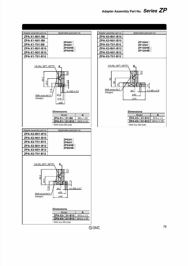
8/12/2019 Ventosa Especial Da Smc
http://slidepdf.com/reader/full/ventosa-especial-da-smc 106/119
1/8 (Rc, NPT, NPTF)
Width across flat 21
(Hexagon)
4 8
. 5
2 6 . 5
1 1
. 53 x M3 x 0.5
ø3
ø18
ø28
5
. 5
A
1 1
Width across flat 21
(Hexagon)
1/8 (Rc, NPT, NPTF)
1 1
. 5
2 6
. 5 4 8
. 5
1 1
ø45
ø34
4 x M4 x 0.7
5
A
ø4
Width across flat 21
(Hexagon)
1/8 (Rc, NPT, NPTF)
ø40
4 x M5 x 0.8
7
ø70
1 1
A
1 3 2
8
5 0
ø4
Adapter assembly part no.
ZPA-X1-B01-B8
ZPA-X1-N01-B8ZPA-X1-T01-B8
ZPA-X1-B01-B10
ZPA-X1-N01-B10
ZPA-X1-T01-B10
ZP40HZP50HZP40HBZP50HB
Applicable pad part no.
Adapter assembly part no.
ZPA-X2-B01-B10
ZPA-X2-N01-B10
ZPA-X2-T01-B10
ZPA-X2-B01-B12
ZPA-X2-N01-B12
ZPA-X2-T01-B12
ZP63HZP80HZP63HBZP80HB
Applicable pad part no.
Adapter assembly part no.
ZPA-X3-B01-B10
ZPA-X3-N01-B10ZPA-X3-T01-B10
ZPA-X3-B01-B12
ZPA-X3-N01-B12
ZPA-X3-T01-B12
ZP100HZP125HZP100HBZP125HB
Applicable pad part no.
Heavy-duty Adapter Assembly Part No. (Type X, Female thread)
Dimensions
Model
M8 x 1.25
M10 x 1.5
ZPA-X1-01-B8
ZPA-X1-01-B10
A
Dimensions
Model
M10 x 1.5
M12 x 1.75
ZPA-X2-01-B10
ZPA-X2-01-B12
A
Dimensions
Model
M10 x 1.5
M12 x 1.75
ZPA-X3-01-B10
ZPA-X3-01-B12
A
∗ With three M3 bolts
∗ With four M4 bolts
∗ With four M5 bolts
76
Series ZP Adapter Assembly Part No.
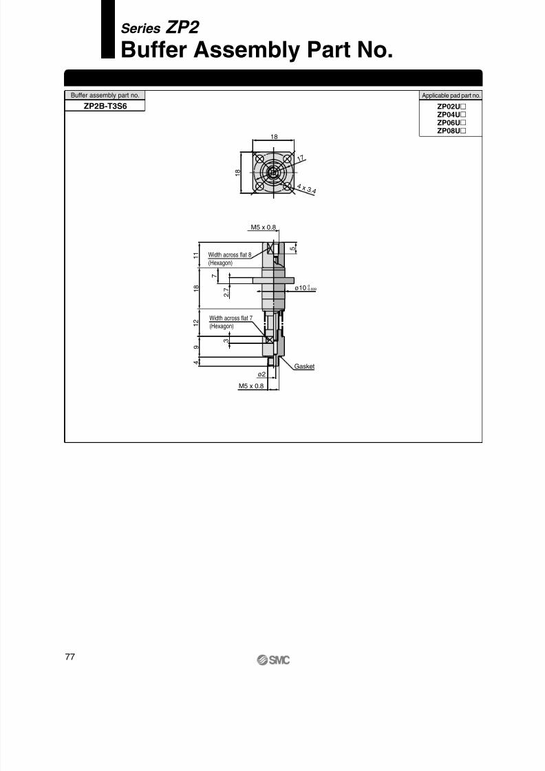
8/12/2019 Ventosa Especial Da Smc
http://slidepdf.com/reader/full/ventosa-especial-da-smc 107/119
Width across flat 8
(Hexagon)
Width across flat 7
(Hexagon)
Gasket
3
1 7
18
2 .
7
7
ø10 0-0.009
9
1 2
1 8
1 1
M5 x 0.8
5
1 8
4 x 3 .4
4
M5 x 0.8
ø2
ZP02UZP04UZP06UZP08U
Applicable pad part no.Buffer assembly part no.
ZP2B-T3S6
Ball Spline
Series ZP2
Buffer Assembly Part No.
77

8/12/2019 Ventosa Especial Da Smc
http://slidepdf.com/reader/full/ventosa-especial-da-smc 108/119
Width across flat 17 (Hexagon)
Width across flat 30
(Hexagon)
Width across flat 17
(Hexagon)
4 x M5 x 0.8
Rc1/8
2 4
A
M22 x 1.5
2
0
2
9 . 5 5
5 . 5
ø40
ø4
3 0 °
8 . 5
ø70
5 0
( B )
1 0
. 1
8 8
Width across flat 30
(Hexagon)
Width across flat 17 (Hexagon)
Width across flat 17
(Hexagon)
4 x M4 x 0.7
Rc1/8
2 4
A
M22 x 1.5
1 9
2 8
. 5 5 4
. 5
3 0 °
ø4
ø34
ø50
8
5 0
( B )
9 . 1
8 8
Width across flat 27 (Hexagon)
Width across flat 14
(Hexagon)
Width across flat 13
(Hexagon)
Rc1/8
3 x M3 x 0.5
M18 x 1.5
A
2 0
. 5
1 4
. 5
2 1
. 5
4 2
. 5
3 0 °
ø30
ø18
ø2
7
3 5
( B )
7 . 3
9
9 Bushing
Bushing
Bushing
ZP40HZP50HZP40HBZP50HB
Applicable pad part no.
ZP63HZP80HZP63HBZP80HB
Applicable pad part no.
ZP100HZP125HZP100HBZP125HB
Applicable pad part no.
ZP2B-TF3JB25
ZP2B-TF3JB50
ZP2B-TF3JB75
ZP2B-TF3JB100
ZP2B-TF3JF25
ZP2B-TF3JF50
ZP2B-TF3JF75
ZP2B-TF3JF100
ZP2B-TF2JB25
ZP2B-TF2JB50
ZP2B-TF2JB75
ZP2B-TF2JB100
ZP2B-TF2JF25
ZP2B-TF2JF50
ZP2B-TF2JF75
ZP2B-TF2JF100
Buffer body(Material: Brass)
Buffer body(Material: Steel)
Buffer assembly part no.
Buffer body(Material: Brass)
Buffer body(Material: Steel)
Buffer assembly part no.
Buffer body(Material: Brass)
Buffer body(Material: Steel)
Buffer assembly part no.
ZP2B-TF1JB25
ZP2B-TF1JB50
ZP2B-TF1JB75
ZP2B-TF1JF25
ZP2B-TF1JF50
ZP2B-TF1JF75
Dimensions
Model
44
80
120
155
ZP2B-TF3(JB/JF)25
ZP2B-TF3(JB/JF)50
ZP2B-TF3(JB/JF)75
ZP2B-TF3(JB/JF)100
A
173.5
209.5
249.5
284.5
B
Dimensions
Model
44
80
120
155
ZP2B-TF2(JB/JF)25
ZP2B-TF2(JB/JF)50
ZP2B-TF2(JB/JF)75
ZP2B-TF2(JB/JF)100
A
172.5
208.5
248.5
283.5
B
Dimensions
Model
40 75
111
ZP2B-TF1(JB/JF)25ZP2B-TF1(JB/JF)50
ZP2B-TF1(JB/JF)75
A
138173
209
B
Heavy-duty Ball Joint Buffer Assembly Part No. (Type T)
∗ With three M3 bolts
∗ With four M4 bolts
∗ With four M5 bolts
∗ Refer to the front matter 30 for nut tightening torque.
78
Series ZP2 Buffer Assembly Part No.

8/12/2019 Ventosa Especial Da Smc
http://slidepdf.com/reader/full/ventosa-especial-da-smc 109/119
Width across flat 17
(Hexagon)
Width across flat 30 (Hexagon)
Width across flat 22 (Hexagon)
Rc1/8
4 x M5 x 0.8
2 0
2 9
. 5
ø70
3 0 °
2
1
4 6 6
8 . 5
A
M22 x 1.5
8 8
ø4
ø40
5 0
( B )
8 . 5
1 0
. 1
Width across flat 27 (Hexagon)
Width across flat 14
(Hexagon)
Width across flat 13
(Hexagon)
M5 x 0.8
3 x M3 x 0.5
3 2
9
9
M18 x 1.5
1
6
1 4
. 5
2 1
. 5
5 0
. 5
7
A
3 5
( B )
7 . 3
Width across flat 22
(Hexagon)
Width across flat 30 (Hexagon)
Width across flat 17(Hexagon)
Rc1/84 x M4 x 0.7
4 5 6
7 . 5
A
M22 x 1.5
1 9
2 8
. 5
2 1
ø50
ø34
ø4
3 0 °
8
5 0
( B )
9 . 1
8 8
ø30
ø18
3 0 °
ø2
Bushing
Bushing
Bushing
ZP40HZP50HZP40HBZP50HB
Applicable pad part no.
ZP2B-XF3JB25
ZP2B-XF3JB50
ZP2B-XF3JB75
ZP2B-XF3JB100
ZP2B-XF3JF25
ZP2B-XF3JF50
ZP2B-XF3JF75
ZP2B-XF3JF100
ZP2B-XF2JB25
ZP2B-XF2JB50
ZP2B-XF2JB75
ZP2B-XF2JB100
ZP2B-XF2JF25
ZP2B-XF2JF50
ZP2B-XF2JF75
ZP2B-XF2JF100
Heavy-duty Ball Joint Buffer Assembly Part No. (Type X)
Dimensions
Model
44
80
120
155
ZP2B-XF3(JB/JF)25
ZP2B-XF3(JB/JF)50
ZP2B-XF3(JB/JF)75
ZP2B-XF3(JB/JF)100
A
183.5
219.5
259.5
294.5
B
Dimensions
Model
44
80
120
155
ZP2B-XF2(JB/JF)25
ZP2B-XF2(JB/JF)50
ZP2B-XF2(JB/JF)75
ZP2B-XF2(JB/JF)100
A
182.5
218.5
258.5
293.5
B
ZP2B-XF1JB25
ZP2B-XF1JB50
ZP2B-XF1JB75
ZP2B-XF1JF25
ZP2B-XF1JF50
ZP2B-XF1JF75
Dimensions
Model
40 75
111
ZP2B-XF1(JB/JF)25ZP2B-XF1(JB/JF)50
ZP2B-XF1(JB/JF)75
A
141.5176.5
212.5
B
ZP63HZP80HZP63HBZP80HB
Applicable pad part no.
ZP100HZP125HZP100HBZP125HB
Applicable pad part no.
∗ With three M3 bolts
∗ With four M4 bolts
∗ With four M5 bolts
∗ Refer to the front matter 30 for nut tightening torque.
Buffer body(Material: Brass)
Buffer body(Material: Steel)
Buffer assembly part no.
Buffer body(Material: Brass)
Buffer body(Material: Steel)
Buffer assembly part no.
Buffer body(Material: Brass)
Buffer body(Material: Steel)
Buffer assembly part no.
79
Series ZP2

8/12/2019 Ventosa Especial Da Smc
http://slidepdf.com/reader/full/ventosa-especial-da-smc 110/119
Width across flat 14 (Hexagon)
1/8 (Rc, NPT, NPTF)Width across flat 27 (Hexagon)
ø28
ø18
ø33 x M3 x 0.5
5 . 5
M18 x 1.5
2 0
. 5
A
1 1
. 5
( B )
3 5 9
9
Width across flat 14 (Hexagon)
1/8 (Rc, NPT, NPTF)
Width across flat 27 (Hexagon)
1 1
. 5
ø45
ø34
4 x M4 x 0.7
5
ø3
M18 x 1.5
2 0
. 5
A
( B )
3 5 9
9
Width across flat 17 (Hexagon)
1/8 (Rc, NPT, NPTF)Width across flat 30 (Hexagon)
M22 x 1.5
2 4
A
1
3
( B )
ø40
ø70
4 x M5 x 0.8
7
ø4
5 0
8 8
ZP40HZP50HZP40HBZP50HB
Applicable pad part no.
ZP63HZP80HZP63HBZP80HB
Applicable pad part no.
ZP100HZP125HZP100HBZP125HB
Applicable pad part no.
Buffer body(Material: Aluminum alloy)
Buffer assembly part no.
ZPB-T3J25-B01
ZPB-T3J25-N01
ZPB-T3J25-T01
ZPB-T3J50-B01
ZPB-T3J50-N01
ZPB-T3J50-T01
ZPB-T3J75-B01
ZPB-T3J75-N01
ZPB-T3J75-T01
ZPB-T3J100-B01ZPB-T3J100-N01
ZPB-T3J100-T01
Buffer body(Material: Aluminum alloy)
Buffer assembly part no.
ZPB-T2J25-B01
ZPB-T2J25-N01
ZPB-T2J25-T01
ZPB-T2J50-B01
ZPB-T2J50-N01ZPB-T2J50-T01
ZPB-T2J75-B01
ZPB-T2J75-N01
ZPB-T2J75-T01
Buffer body(Material: Aluminum alloy)
Buffer assembly part no.
ZPB-T1J25-B01
ZPB-T1J25-N01
ZPB-T1J25-T01
ZPB-T1J50-B01
ZPB-T1J50-N01
ZPB-T1J50-T01
ZPB-T1J75-B01
ZPB-T1J75-N01
ZPB-T1J75-T01
Heavy-duty Buffer Assembly Part No. (Type T)
Dimensions
Model
40 75
111
A
107142
178
B
∗ With three M3 bolts
ZPB-T1J25-01ZPB-T1J50-01
ZPB-T1J75-01
Dimensions
Model
40
75
111
A
107
142
178
B
∗ With four M4 bolts
ZPB-T2J25-01
ZPB-T2J50-01
ZPB-T2J75-01
Dimensions
Model
44
80
120
155
A
131
167
207
242
B
∗ With four M5 bolts
ZPB-T3J25-01
ZPB-T3J50-01
ZPB-T3J75-01
ZPB-T3J100-01
∗ Refer to the front matter 30for nut tightening torque.
Series ZP
Buffer Assembly Part No.
80

8/12/2019 Ventosa Especial Da Smc
http://slidepdf.com/reader/full/ventosa-especial-da-smc 111/119
Width across flat 14 (Hexagon)
1/8 (Rc, NPT, NPTF)Width across flat 27 (Hexagon)
Bushing
ø28
ø18
ø3
3 x M3 x 0.5
5 . 5
M18 x 1.5
2 0
. 5
A
1 1
. 5
( B )
3 5 9
9
Width across flat 14 (Hexagon)
1/8 (Rc, NPT, NPTF)
Width across flat 27 (Hexagon)
1 1
. 5
ø45
ø34
4 x M4 x 0.7
5
ø3
M18 x 1.5
2 0
. 5
A
( B )
3 5 9
9
Bushing
Bushing
Width across flat 17 (Hexagon)
1/8 (Rc, NPT, NPTF)Width across flat 30 (Hexagon)
M22 x 1.5
2 4
A
1 3
( B )
ø40
ø70
4 x M5 x 0.8
7
ø4
5 0
8 8
ZPB-T3JB25-B01
ZPB-T3JB25-N01
ZPB-T3JB25-T01
ZPB-T3JB50-B01
ZPB-T3JB50-N01
ZPB-T3JB50-T01
ZPB-T3JB75-B01
ZPB-T3JB75-N01
ZPB-T3JB75-T01
ZPB-T3JB100-B01ZPB-T3JB100-N01
ZPB-T3JB100-T01
ZPB-T3JF25-B01
ZPB-T3JF25-N01
ZPB-T3JF25-T01
ZPB-T3JF50-B01
ZPB-T3JF50-N01
ZPB-T3JF50-T01
ZPB-T3JF75-B01
ZPB-T3JF75-N01
ZPB-T3JF75-T01
ZPB-T3JF100-B01ZPB-T3JF100-N01
ZPB-T3JF100-T01
ZPB-T2JB25-B01
ZPB-T2JB25-N01
ZPB-T2JB25-T01
ZPB-T2JB50-B01
ZPB-T2JB50-N01ZPB-T2JB50-T01
ZPB-T2JB75-B01
ZPB-T2JB75-N01
ZPB-T2JB75-T01
ZPB-T2JF25-B01
ZPB-T2JF25-N01
ZPB-T2JF25-T01
ZPB-T2JF50-B01
ZPB-T2JF50-N01ZPB-T2JF50-T01
ZPB-T2JF75-B01
ZPB-T2JF75-N01
ZPB-T2JF75-T01
ZPB-T1JB25-B01
ZPB-T1JB25-N01
ZPB-T1JB25-T01
ZPB-T1JB50-B01
ZPB-T1JB50-N01
ZPB-T1JB50-T01
ZPB-T1JB75-B01
ZPB-T1JB75-N01
ZPB-T1JB75-T01
ZPB-T1JF25-B01
ZPB-T1JF25-N01
ZPB-T1JF25-T01
ZPB-T1JF50-B01
ZPB-T1JF50-N01
ZPB-T1JF50-T01
ZPB-T1JF75-B01
ZPB-T1JF75-N01
ZPB-T1JF75-T01
ZP40HZP50HZP40HBZP50HB
Applicable pad part no.
ZP63HZP80HZP63HBZP80HB
Applicable pad part no.
ZP100HZP125HZP100HBZP125HB
Applicable pad part no.
Dimensions
Model
44
80
120
155
A
131
167
207
242
B
ZPB-T3(JB/JF)25-01
ZPB-T3(JB/JF)50-01
ZPB-T3(JB/JF)75-01
ZPB-T3(JB/JF)100-01
Heavy-duty Buffer Assembly Part No. (Type T)
Dimensions
Model
40
75
111
A
107
142
178
B
ZPB-T2(JB/JF)25-01
ZPB-T2(JB/JF)50-01
ZPB-T2(JB/JF)75-01
∗ With four M4 bolts
∗ With four M5 bolts
Dimensions
Model
40 75
111
A
107142
178
B
ZPB-T1(JB/JF)25-01ZPB-T1(JB/JF)50-01
ZPB-T1(JB/JF)75-01
∗ With three M3 bolts
∗ Refer to the front matter 30 for nut tightening torque.
Buffer body(Material: Brass)
Buffer body(Material: Steel)
Buffer assembly part no.
Buffer body(Material: Brass)
Buffer body(Material: Steel)
Buffer assembly part no.
Buffer body(Material: Brass)
Buffer body(Material: Steel)
Buffer assembly part no.
81
Series ZP
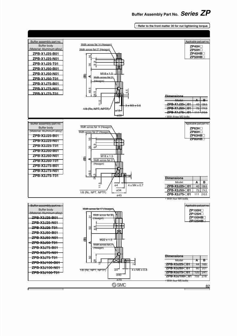
8/12/2019 Ventosa Especial Da Smc
http://slidepdf.com/reader/full/ventosa-especial-da-smc 112/119
1/8 (Rc, NPT, NPTF)
Width across flat 27 (Hexagon)
Width across flat 14 (Hexagon)
Width across flat 21
(Hexagon)
ø28
ø18
ø33 x M3 x 0.5
5 . 5
1
1 . 5
A
3 5
1 6
( B ) M18 x 1.5
2 6
. 5 4 8
. 5
9
9
Width across flat 27 (Hexagon)
Width across flat 14 (Hexagon)
Width across flat 21
(Hexagon)
ø45
ø34
4 x M4 x 0.7
5
ø4
( B )
1 6
3 5
M18 x 1.5 A
1 1
. 5
2 6
. 5 4 8
. 5
1/8 (Rc, NPT, NPTF)
9
9
Width across flat 21(Hexagon)
Width across flat 17 (Hexagon)
Width across flat 30(Hexagon)
ø40
ø4
7
4 x M5 x 0.8
ø70
A
5 0
2 1
M22 x 1.5
1 3
( B )
2
8 5 0
1/8 (Rc, NPT, NPTF)
8 8
Buffer body(Material: Aluminum alloy)
Buffer assembly part no.
ZPB-X3J25-B01
ZPB-X3J25-N01
ZPB-X3J25-T01
ZPB-X3J50-B01
ZPB-X3J50-N01
ZPB-X3J50-T01
ZPB-X3J75-B01
ZPB-X3J75-N01
ZPB-X3J75-T01
ZPB-X3J100-B01ZPB-X3J100-N01
ZPB-X3J100-T01
Buffer body(Material: Aluminum alloy)
Buffer assembly part no.
ZPB-X2J25-B01
ZPB-X2J25-N01
ZPB-X2J25-T01
ZPB-X2J50-B01
ZPB-X2J50-N01ZPB-X2J50-T01
ZPB-X2J75-B01
ZPB-X2J75-N01
ZPB-X2J75-T01
Buffer body(Material: Aluminum alloy)
Buffer assembly part no.
ZPB-X1J25-B01
ZPB-X1J25-N01
ZPB-X1J25-T01
ZPB-X1J50-B01
ZPB-X1J50-N01
ZPB-X1J50-T01
ZPB-X1J75-B01
ZPB-X1J75-N01
ZPB-X1J75-T01
ZP40HZP50HZP40HBZP50HB
Applicable pad part no.
ZP63HZP80HZP63HBZP80HB
Applicable pad part no.
ZP100HZP125HZP100HBZP125HB
Applicable pad part no.
Dimensions
Model
40 75
111
A
139.5174.5
210.5
B
ZPB-X1J25-01ZPB-X1J50-01
ZPB-X1J75-01
Dimensions
Model
40
75
111
A
139.5
174.5
210.5
B
ZPB-X2J25-01
ZPB-X2J50-01
ZPB-X2J75-01
Dimensions
Model
44
80
120
155
A
165
201
241
276
B
ZPB-X3J25-01
ZPB-X3J50-01
ZPB-X3J75-01
ZPB-X3J100-01
Heavy-duty Buffer Assembly Part No. (Type X)
∗ With four M4 bolts
∗ With three M3 bolts
∗ With four M5 bolts
∗ Refer to the front matter 30 for nut tightening torque.
82
Series ZP Buffer Assembly Part No.

8/12/2019 Ventosa Especial Da Smc
http://slidepdf.com/reader/full/ventosa-especial-da-smc 113/119

8/12/2019 Ventosa Especial Da Smc
http://slidepdf.com/reader/full/ventosa-especial-da-smc 114/119
84
Design/Selection
Caution1. Mounting the suction filter
Because the suction of vacuum equipment acts not only onwork pieces but also on dust or water droplets in the surround-ing atmosphere, steps must be taken to prevent their penetra-tion into the equipment’s interior.Even when using equipment equipped with filters, if there is aconsiderable amount of dust in the environment, use a sepa-rately ordered large-size filter as well.
If there is a possibility of water droplets being sucked in by thevacuum, use a drain separator for vacuum.
2. The maximum vacuum pressure of the va-cuum ejector is affected by the atmosphericpressure of the operating environment.As atmospheric pressure changes based on altitude, climate,etc., the actual maximum vacuum pressure may not reach the
value listed in the specifications.3. For information on related items, such as di-
rectional control equipment and drive equip-ment, refer to the caution sections in eachrespective catalog.
4. Do not use the product in an environment thatexposes it to vibration. If the product is usedin such an environment, we can offer a locknut type product to prevent it from loosening.Please contact SMC for model number.
Mounting
Warning1. Operation manual
Install the products and operate them only after reading theoperation manual carefully and understanding its contents.Also, keep the manual available whenever necessary.
2. Ensure sufficient space for maintenance ac-tivities.When installing the products, allow access for maintenance.
3. Tighten threads with the proper tighteningtorque.When installing the products, follow the listed torque specifica-tions.
4. Do not obstruct the exhaust port of the ejector.If the exhaust port is obstructed when mounted, a vacuum willnot be generated. Also, do not obstruct the exhaust port withthe goal of removing the workpiece. It may cause damage tothe equipment.
8. Check valveSMC can issue no guarantees regarding the maintenance ofworkpiece adsorption when using check valves. Take sepa-rate safety measures to prevent work pieces from dropping inthe case of an electrical power outage, etc.Please consult with SMC when using check valves as ameans of preventing interference caused by the exhaust fromnearby ejectors.
Vacuum EquipmentPrecautions 1Be sure to read this before handling.
Warning1. Confirm the specifications.
Products represented in this catalog are designed only for usein compressed air systems (including vacuum).Do not operate at pressures or temperatures, etc., beyond therange of specifications, as this can cause damage or malfunc-tion. (Refer to the specifications.)Please contact SMC when using a fluid other than com-pressed air (including vacuum).We do not guarantee against any damage if the product isused outside of the specification range.
2. Safe designs should be developed, whichaccount for the possibility of accidents re-sulting from a drop in vacuum pressure dueto power failure or trouble with the air sup-ply, etc.If vacuum pressure drops and there is a loss of vacuum padadsorption force, work pieces being carried may fall, causinghuman injury or damage to machinery. Sufficient safety meas-ures should be implemented, such as drop prevention, toavoid any accidents.
3. Follow vacuum specifications for vacuumswitching valves and vacuum release valves.If non-vacuum equipment is installed in a vacuum piping, va-cuum leakage will occur. Therefore, select only equipment forvacuum specifications.
4. Select an ejector which has a suitable suc-tion flow rate.<When there is vacuum leakage from the workpiece or thepiping>If the ejector’s suction flow rate is too low, the adsorption willbe poor.
<When piping is long or the diameter is large>The adsorption response time will delay due to the increasedvolume of the piping.Select an ejector with a suitable suction flow rate by referringto the technical data.
5. If the suction flow rate is too high, setting ofvacuum switch will become difficult.Setting the vacuum switch when absorbing a small (few milli-
meter) workpiece will sometimes become difficult, if the selec-ted ejector has a high suction rate and there is a small pres-sure difference when absorbing and releasing the workpiece.
6. When two or more pads are piped to oneejector, if one pad releases its workpiece,the other pads will also release.When one pad releases its workpiece, there is a drop in va-cuum pressure which causes the other pad to release itsworkpiece as well.
7. Do not disassemble the product or make anymodifications, including additional machin-ing.It may cause human injury and/or an accident.
When disassembling or assembling the product for the pur-pose of replacing parts, etc., be certain to follow the operationmanual or catalogs.

8/12/2019 Ventosa Especial Da Smc
http://slidepdf.com/reader/full/ventosa-especial-da-smc 115/119
Air Supply
Warning3. Drain flushing
If condensation in the water separator and drain bowl is notemptied on a regular basis, the bowl will overflow and allowthe condensation to enter the compressed air lines. It causesmalfunction of pneumatic equipment.If the drain bowl is difficult to check and remove, installation ofa drain bowl with an auto drain option is recommended.For compressed air quality, refer to SMC’s Best Pneumaticscatalog.
4. Use clean air.Do not use compressed air that contains chemicals, syntheticoils including organic solvents, salt or corrosive gases, etc., asit can cause damage or malfunction.
Operating Environment
1. Do not use in an atmosphere having corro-sive gases, chemicals, sea water, water, wa-ter steam, or where there is direct contactwith any of these.
2. Do not use in a place subject to heavy vibra-tion and/or shock.
3. Do not use in an environment where flamma-ble gas or explosive gas exists. Usage maycause a fire or explosion. The products donot have an explosion proof construction.
4. The valve should not be exposed to prolon-ged sunlight. Use a protective cover.
5. Remove any sources of excessive heat.
6. In locations where there is contact with spat-ter from water, oil, solder, etc., take suitableprotective measures.
7. In cases where the vacuum unit is surroun-
ded by other equipment, etc., or the unit isenergized for an extended time, take meas-ures to exhaust excess heat so that the tem-perature should be within specifications.
Caution1. Under certain conditions, the exhaust of the
vacuum ejector may generate intermittentnoises, and vacuum pressure may be un-even.Using the ejector under these conditions will not result indecreased performance, but if the intermittent noise becomesa nuisance, or there is an adverse effect on the operation ofthe vacuum pressure switch, try lowering or raising the supplypressure of the vacuum ejector to find a supply pressure levelat which the intermittent noise ceases.
Piping
Caution
Warning
1. Refer to the Fittings and Tubing Precautions(Best Pneumatics No. 6) for handling one-touch fittings.
2. Preparation before pipingBefore piping is connected, it should be thoroughly blown outwith air (flushing) or washed to remove chips, cutting oil andother debris from inside the pipe.
3. Wrapping of pipe tapeWhen screwing piping or fittings into ports, ensure that chipsfrom the pipe threads or sealing material do not enter thepiping. Also, if pipe tape is used, leave 1.5 to 2 thread ridgesexposed at the end of the threads.
Air Supply
Warning1. Type of fluids
Please consult with SMC when using the product inapplications other than compressed air.
2. When there is a large amount of drainage.
Compressed air containing a large amount of drainage cancause malfunction of pneumatic equipment. An air dryer orwater separator should be installed upstream from filters.
4. Use piping with an adequate conductance.Select equipment and piping for the vacuum side which hasan adequate conductance so that the ejector's maximumsuction flow rate can be accommodated by the piping.
Also, make sure that there are no unnecessary restrictions orleaks, etc., along the course of the piping. Furthermore,design of the air supply should be performed while taking intoconsideration the ejector's maximum air consumption and theair consumption of other pneumatic circuits.
5. Avoid disorganized piping.Piping which is direct and of the shortest possible lengthshould be used for both the vacuum and supply sides.Disorganized piping should be avoided. Unnecessary lengthincreases the piping volume, and thus increases the responsetime.
6. Use piping with a large conductance on theexhaust side of the ejector.If the exhaust piping is restrictive, there will be a decline in the
ejector’s performance.
7. Be certain that there are no crushed areas inthe piping due to damage or bending.
Vacuum EquipmentPrecautions 2Be sure to read this before handling.
Windingdirection
Pipe tape
E x p o s e a p p r o x . 2 t h r e a d s
85

8/12/2019 Ventosa Especial Da Smc
http://slidepdf.com/reader/full/ventosa-especial-da-smc 116/119

8/12/2019 Ventosa Especial Da Smc
http://slidepdf.com/reader/full/ventosa-especial-da-smc 117/119

8/12/2019 Ventosa Especial Da Smc
http://slidepdf.com/reader/full/ventosa-especial-da-smc 118/119

8/12/2019 Ventosa Especial Da Smc
http://slidepdf.com/reader/full/ventosa-especial-da-smc 119/119
1. The compatibility of the product is the responsibility of theperson who designs the equipment or decides itsspecifications.Since the product specified here is used under various operating
conditions, its compatibility with specific equipment must be decided by
the person who designs the equipment or decides its specifications
based on necessary analysis and test results. The expected performance
and safety assurance of the equipment will be the responsibility of the
person who has determined its compatibility with the product. This person
should also continuously review all specifications of the product referring
to its latest catalog information, with a view to giving due consideration to
any possibility of equipment failure when configuring the equipment.
2. Only personnel with appropriate training should operatemachinery and equipment.The product specified here may become unsafe if handled incorrectly.
The assembly, operation and maintenance of machines or equipment
including our products must be performed by an operator who is
appropriately trained and experienced.
3. Do not service or attempt to remove product and
machinery/equipment until safety is confirmed.
1. The inspection and maintenance of machinery/equipment should only
be performed after measures to prevent falling or runaway of the
driven objects have been confirmed.
2. When the product is to be removed, confirm that the safety measures
as mentioned above are implemented and the power from any
appropriate source is cut, and read and understand the specificproduct precautions of all relevant products carefully.
3. Before machinery/equipment is restarted, take measures to prevent
unexpected operation and malfunction.
4. Contact SMC beforehand and take special consideration ofsafety measures if the product is to be used in any of thefollowing conditions.
Limited warranty and Disclaimer/ Compliance RequirementsThe product used is subject to the following “Limited warranty and
Disclaimer” and “Compliance Requirements”.
Read and accept them before using the product.
1. The product is provided for use in manufacturing industries.
The product herein described is basically provided for peaceful use in
manufacturing industries.
If considering using the product in other industries, consult SMC
beforehand and exchange specifications or a contract if necessary.
If anything is unclear, contact your nearest sales branch.
Limited warranty and Disclaimer
1. The warranty period of the product is 1 year in service or 1.5
years after the product is delivered.∗2)
Also, the product may have specified durability, running distance or
replacement parts. Please consult your nearest sales branch.
2. For any failure or damage reported within the warranty period which is
clearly our responsibility, a replacement product or necessary parts will
be provided.
This limited warranty applies only to our product independently, and not
to any other damage incurred due to the failure of the product.
3. Prior to using SMC products, please read and understand the warranty
terms and disclaimers noted in the specified catalog for the particular
products.
∗2) Vacuum pads are excluded from this 1 year warranty
These safety instructions are intended to prevent hazardous situations and/orequipment damage. These instructions indicate the level of potential hazard withthe labels of “Caution,” “Warning” or “Danger.” They are all important notes forsafety and must be followed in addition to International Standards (ISO/IEC)∗1),and other safety regulations.
∗1) ISO 4414: Pneumatic fluid power – General rules relating to systems.
ISO 4413: Hydraulic fluid power – General rules relating to systems.
IEC 60204-1: Safety of machinery – Electrical equipment of machines.(Part 1: General requirements)
ISO 10218-1: Manipulating industrial robots - Safety.
etc.
Caution indicates a hazard with a low level of riskwhich, if not avoided, could result in minor ormoderate injury.
Warning indicates a hazard with a medium level of
risk which, if not avoided, could result in death orserious injury.
Caution:
Warning:
Danger :Danger indicates a hazard with a high level of riskwhich, if not avoided, will result in death or seriousinjury.
Safety Instructions
Warning Caution