
Venting. . . System Design for Pneumatic Fill! • Proper design compensates for air surge • Vent...
32
Venting. . . System Design for Pneumatic Fill! Rev - January 2006
Transcript of Venting. . . System Design for Pneumatic Fill! • Proper design compensates for air surge • Vent...

Venting. . .
System Design for Pneumatic Fill!
Rev - January 2006
Table of Contents
1) SAFE-Surge™ Value Message 2) SAFE-Surge™ Flyer
3) Technical Bulletin –
Venting: Design for ACFM
4) R-S-H Engineering a. HCL Unloading Study b. Appendix – Calculations c. Assumption Recap
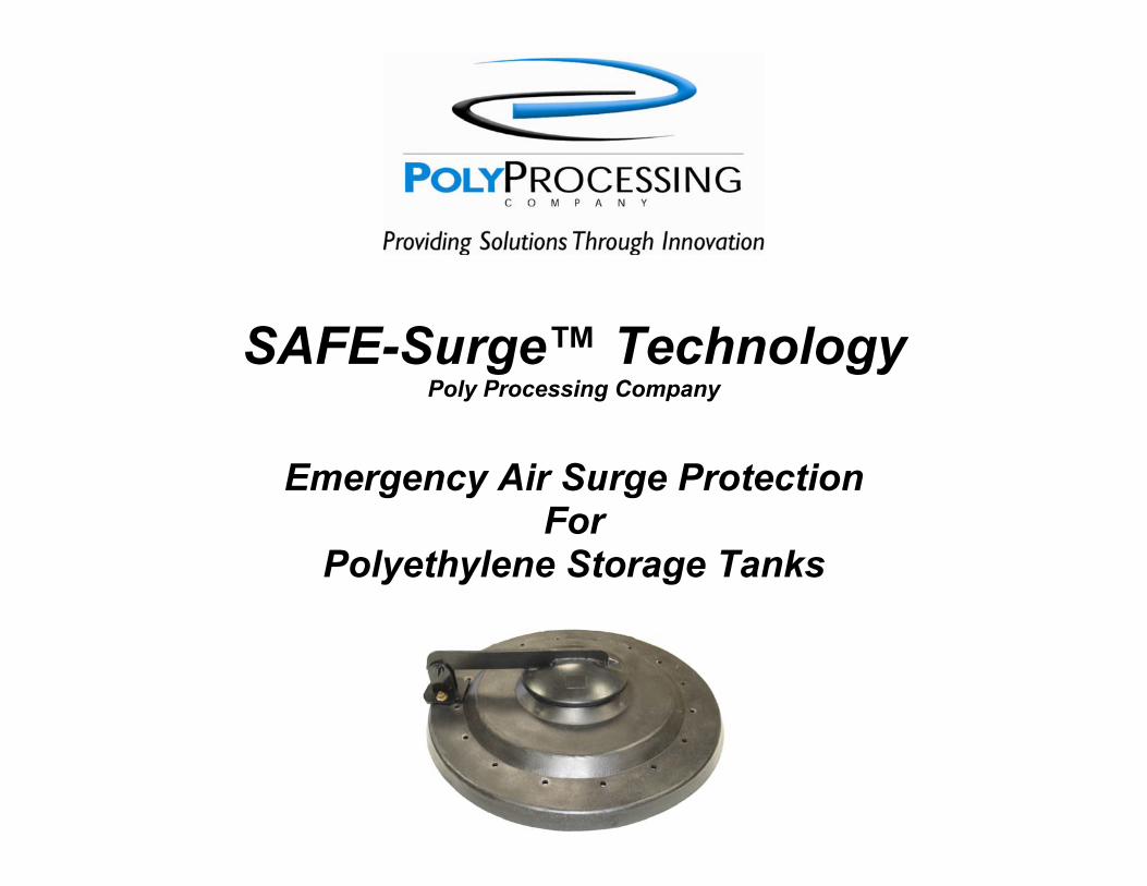
SAFE-Surge™ Technology Poly Processing Company
Emergency Air Surge Protection For
Polyethylene Storage Tanks
Assumptions:
• Proper design compensates for air surge
• Vent capacity ≥ ACFM at line purge • Adequate venting mitigates fitting
leaks and increases tank life
Critical Issue . . . ACFM! • Tanker Discharge Hose Size • Tank Inlet Pipe Size • Tank Vent Size Plan for 30 p.s.i. at line purge!
Helping Our Customers . . .
Solve Problems • Venting design deficiencies for
pneumatic filling
Manage Risk • ACFM at line purge (AIR CUBIC FEET PER MINUTE)
Enhance Your Profits • Continuous Operation
In-Use Customer Values
Increased Safety Margin
Increased Tank Life
Peace of Mind
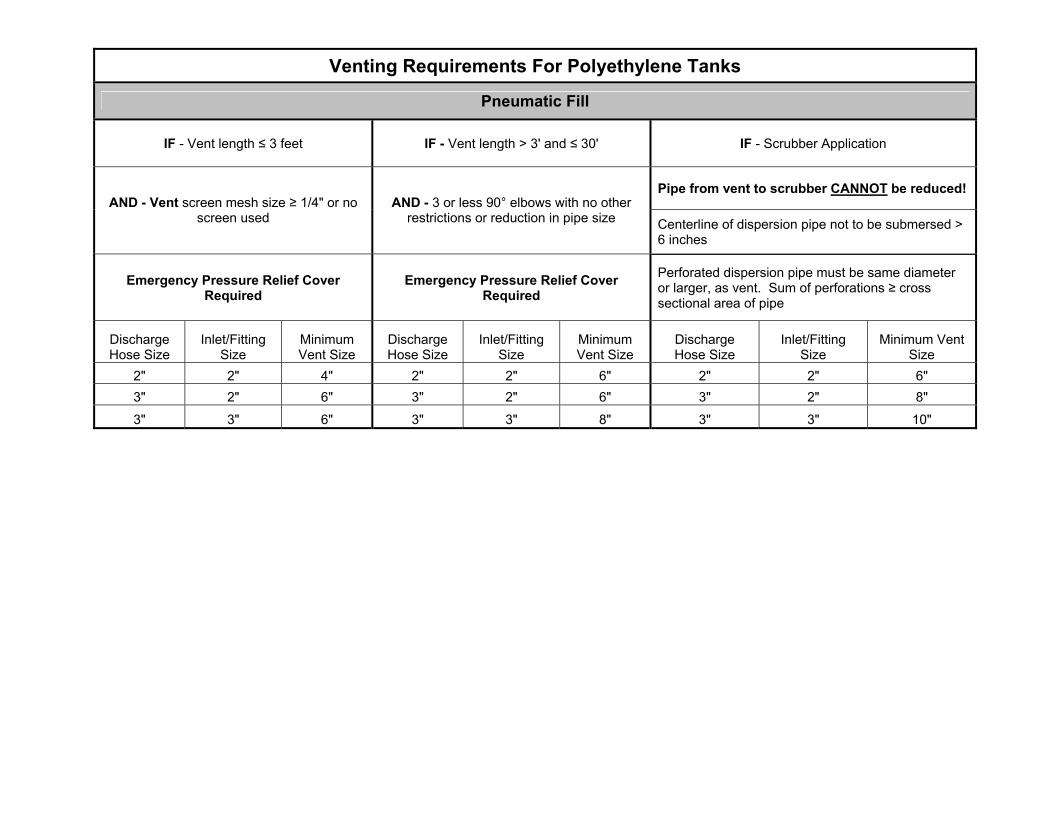
Venting Requirements For Polyethylene Tanks
Pneumatic Fill
IF - Vent length ≤ 3 feet IF - Vent length > 3' and ≤ 30' IF - Scrubber Application
Pipe from vent to scrubber CANNOT be reduced! AND - Vent screen mesh size ≥ 1/4" or no
screen used AND - 3 or less 90° elbows with no other
restrictions or reduction in pipe size Centerline of dispersion pipe not to be submersed > 6 inches
Emergency Pressure Relief Cover Required
Emergency Pressure Relief Cover Required
Perforated dispersion pipe must be same diameter or larger, as vent. Sum of perforations ≥ cross sectional area of pipe
Discharge Hose Size
Inlet/Fitting Size
Minimum Vent Size
Discharge Hose Size
Inlet/Fitting Size
Minimum Vent Size
Discharge Hose Size
Inlet/Fitting Size
Minimum Vent Size
2" 2" 4" 2" 2" 6" 2" 2" 6" 3" 2" 6" 3" 2" 6" 3" 2" 8"
3" 3" 6" 3" 3" 8" 3" 3" 10"
Helping Our Customers . . .
Solve Problems • Proper design compensates for
pneumatic filling
Manage Risk • Vent capacity ≥ ACFM at line purge
Enhance Your Profits • Continuous Operation
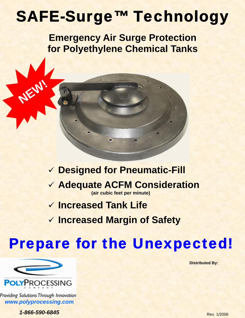
SAFE-Surge™ Technology
Emergency Air Surge Protection for Polyethylene Chemical Tanks
www.polyprocessing.com
1-866-590-6845
Distributed By:
Designed for Pneumatic-Fill
Adequate ACFM Consideration (air cubic feet per minute)
Increased Tank Life
Increased Margin of Safety
Prepare for the Unexpected!
NEW!
Rev. 1/2006
Technical Bulletin
Date: January 2006 Rev. -
Venting – Design for ACFM
(Air Cubic Feet per Minute)
Technical Bulletin 1 Poly Processing Company
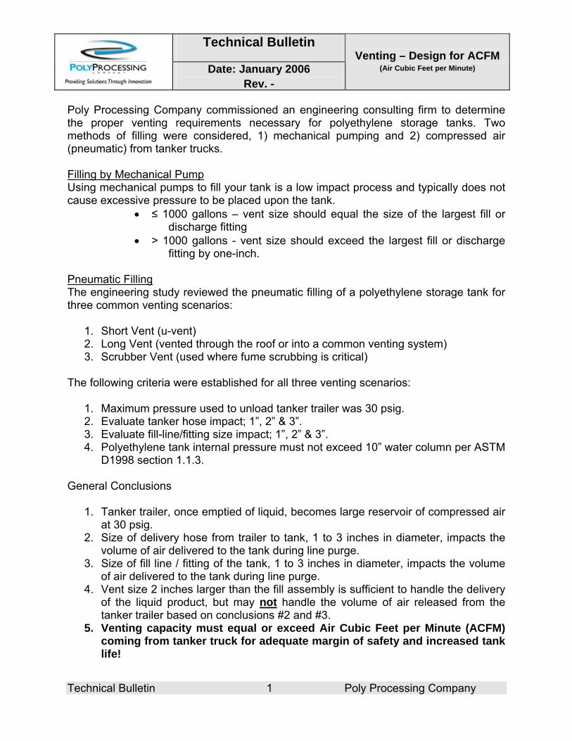
Poly Processing Company commissioned an engineering consulting firm to determine the proper venting requirements necessary for polyethylene storage tanks. Two methods of filling were considered, 1) mechanical pumping and 2) compressed air (pneumatic) from tanker trucks. Filling by Mechanical Pump Using mechanical pumps to fill your tank is a low impact process and typically does not cause excessive pressure to be placed upon the tank.
• ≤ 1000 gallons – vent size should equal the size of the largest fill or discharge fitting
• > 1000 gallons - vent size should exceed the largest fill or discharge fitting by one-inch.
Pneumatic Filling The engineering study reviewed the pneumatic filling of a polyethylene storage tank for three common venting scenarios:
1. Short Vent (u-vent) 2. Long Vent (vented through the roof or into a common venting system) 3. Scrubber Vent (used where fume scrubbing is critical)
The following criteria were established for all three venting scenarios:
1. Maximum pressure used to unload tanker trailer was 30 psig. 2. Evaluate tanker hose impact; 1”, 2” & 3”. 3. Evaluate fill-line/fitting size impact; 1”, 2” & 3”. 4. Polyethylene tank internal pressure must not exceed 10” water column per ASTM
D1998 section 1.1.3. General Conclusions
1. Tanker trailer, once emptied of liquid, becomes large reservoir of compressed air at 30 psig.
2. Size of delivery hose from trailer to tank, 1 to 3 inches in diameter, impacts the volume of air delivered to the tank during line purge.
3. Size of fill line / fitting of the tank, 1 to 3 inches in diameter, impacts the volume of air delivered to the tank during line purge.
4. Vent size 2 inches larger than the fill assembly is sufficient to handle the delivery of the liquid product, but may not handle the volume of air released from the tanker trailer based on conclusions #2 and #3.
5. Venting capacity must equal or exceed Air Cubic Feet per Minute (ACFM) coming from tanker truck for adequate margin of safety and increased tank life!
Technical Bulletin
Date: January 2006 Rev. -
Venting – Design for ACFM
(Air Cubic Feet per Minute)
Technical Bulletin 2 Poly Processing Company
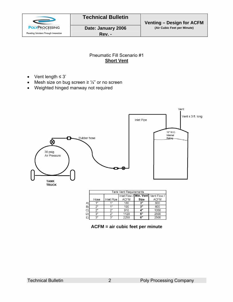
Pneumatic Fill Scenario #1 Short Vent
• Vent length ≤ 3’ • Mesh size on bug screen ≥ ¼” or no screen • Weighted hinged manway not required
ACFM = air cubic feet per minute
Technical Bulletin
Date: January 2006 Rev. -
Venting – Design for ACFM
(Air Cubic Feet per Minute)
Technical Bulletin 3 Poly Processing Company
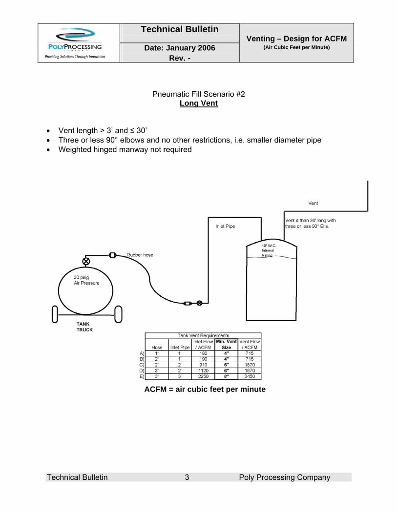
Pneumatic Fill Scenario #2 Long Vent
• Vent length > 3’ and ≤ 30’ • Three or less 90° elbows and no other restrictions, i.e. smaller diameter pipe • Weighted hinged manway not required
ACFM = air cubic feet per minute
Technical Bulletin
Date: January 2006 Rev. -
Venting – Design for ACFM
(Air Cubic Feet per Minute)
Technical Bulletin 4 Poly Processing Company
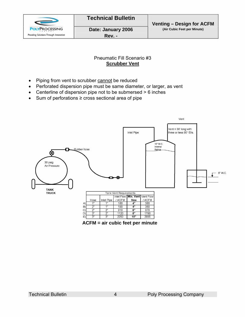
Pneumatic Fill Scenario #3 Scrubber Vent
• Piping from vent to scrubber cannot be reduced • Perforated dispersion pipe must be same diameter, or larger, as vent • Centerline of dispersion pipe not to be submersed > 6 inches • Sum of perforations ≥ cross sectional area of pipe
ACFM = air cubic feet per minute
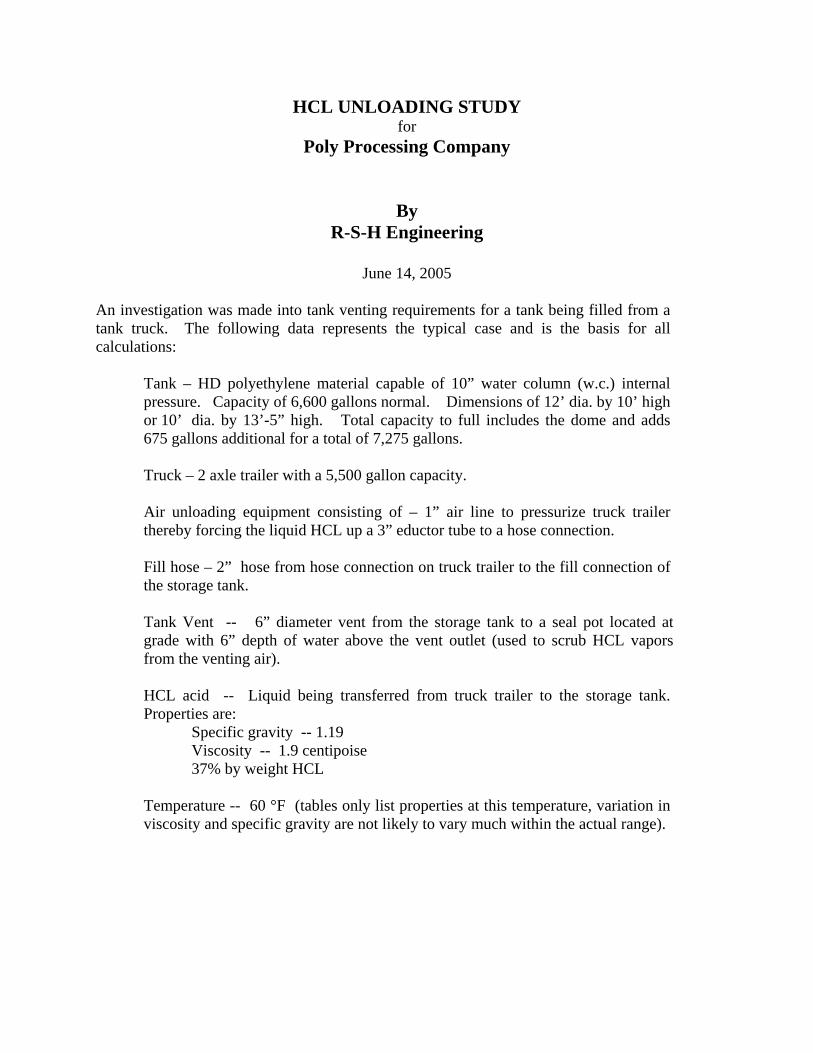
HCL UNLOADING STUDY for
Poly Processing Company
By
R-S-H Engineering
June 14, 2005
An investigation was made into tank venting requirements for a tank being filled from a tank truck. The following data represents the typical case and is the basis for all calculations:
Tank – HD polyethylene material capable of 10” water column (w.c.) internal pressure. Capacity of 6,600 gallons normal. Dimensions of 12’ dia. by 10’ high or 10’ dia. by 13’-5” high. Total capacity to full includes the dome and adds 675 gallons additional for a total of 7,275 gallons.
Truck – 2 axle trailer with a 5,500 gallon capacity.
Air unloading equipment consisting of – 1” air line to pressurize truck trailer thereby forcing the liquid HCL up a 3” eductor tube to a hose connection.
Fill hose – 2” hose from hose connection on truck trailer to the fill connection of the storage tank.
Tank Vent -- 6” diameter vent from the storage tank to a seal pot located at grade with 6” depth of water above the vent outlet (used to scrub HCL vapors from the venting air).
HCL acid -- Liquid being transferred from truck trailer to the storage tank. Properties are: Specific gravity -- 1.19 Viscosity -- 1.9 centipoise 37% by weight HCL
Temperature -- 60 °F (tables only list properties at this temperature, variation in viscosity and specific gravity are not likely to vary much within the actual range).
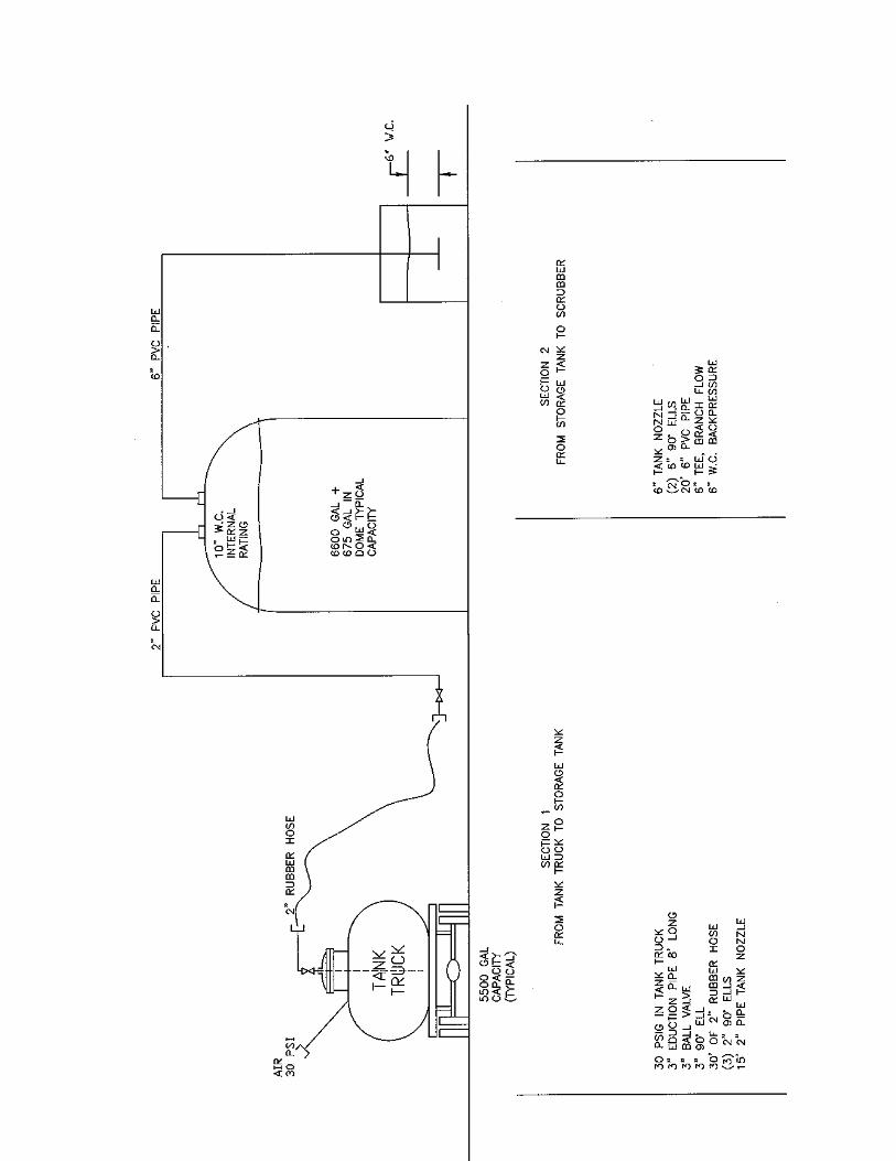
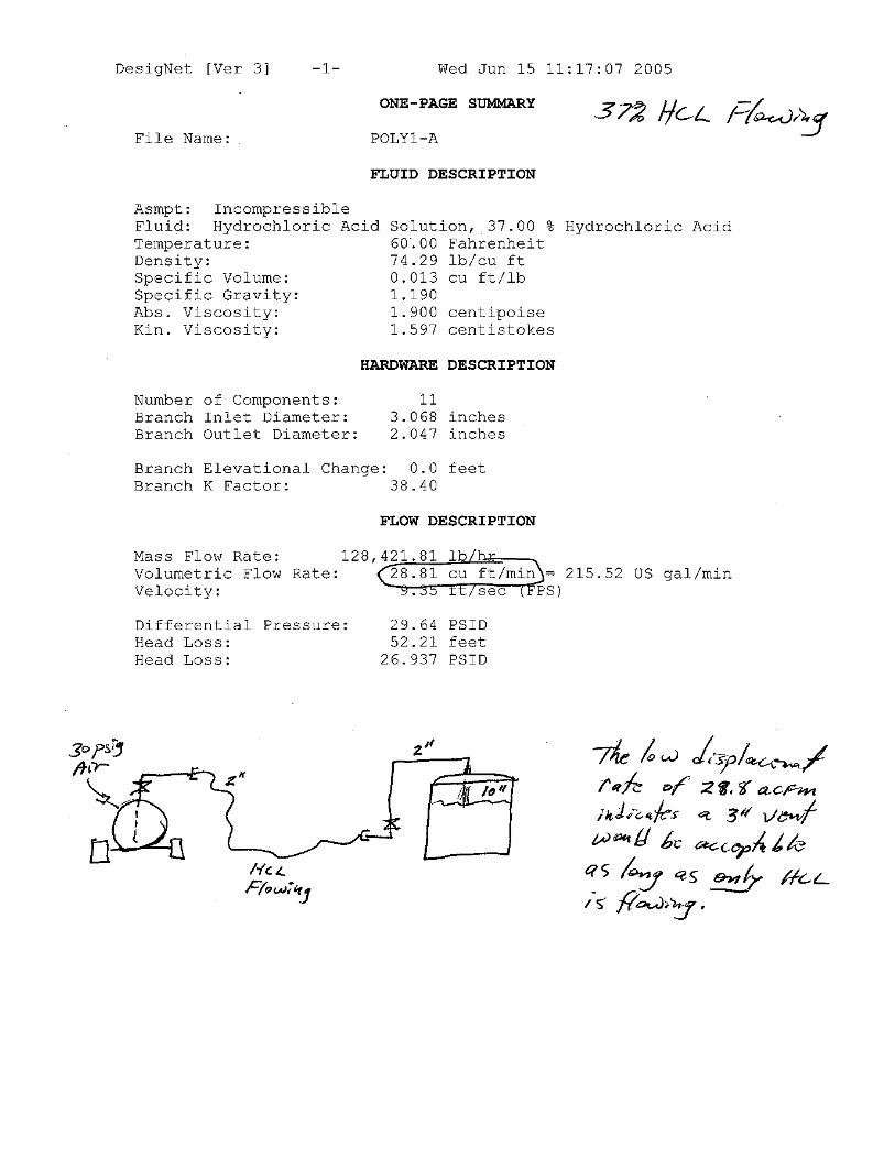
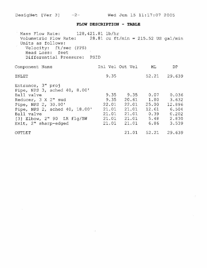
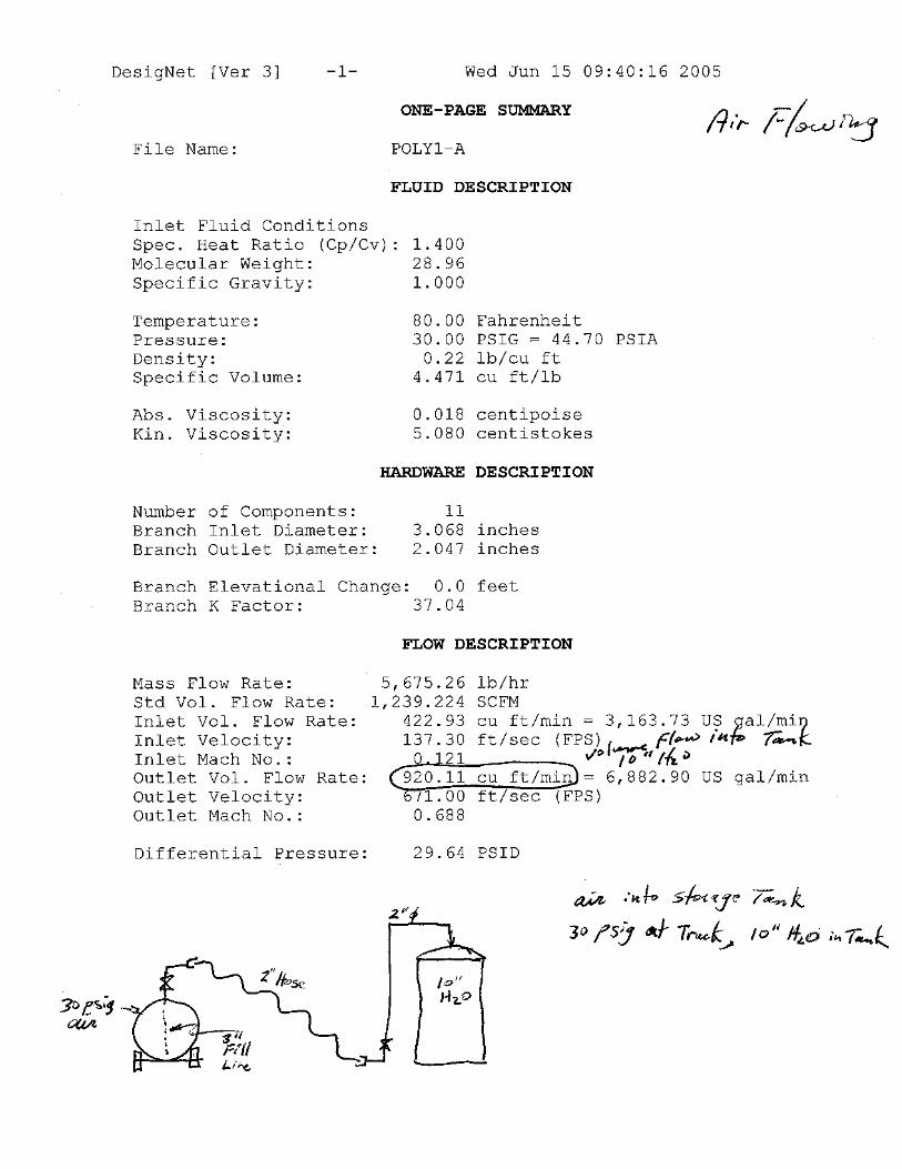
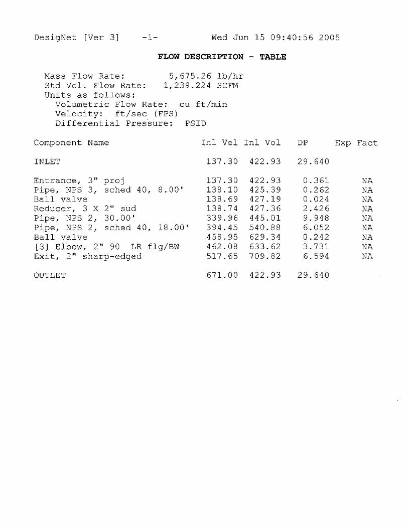
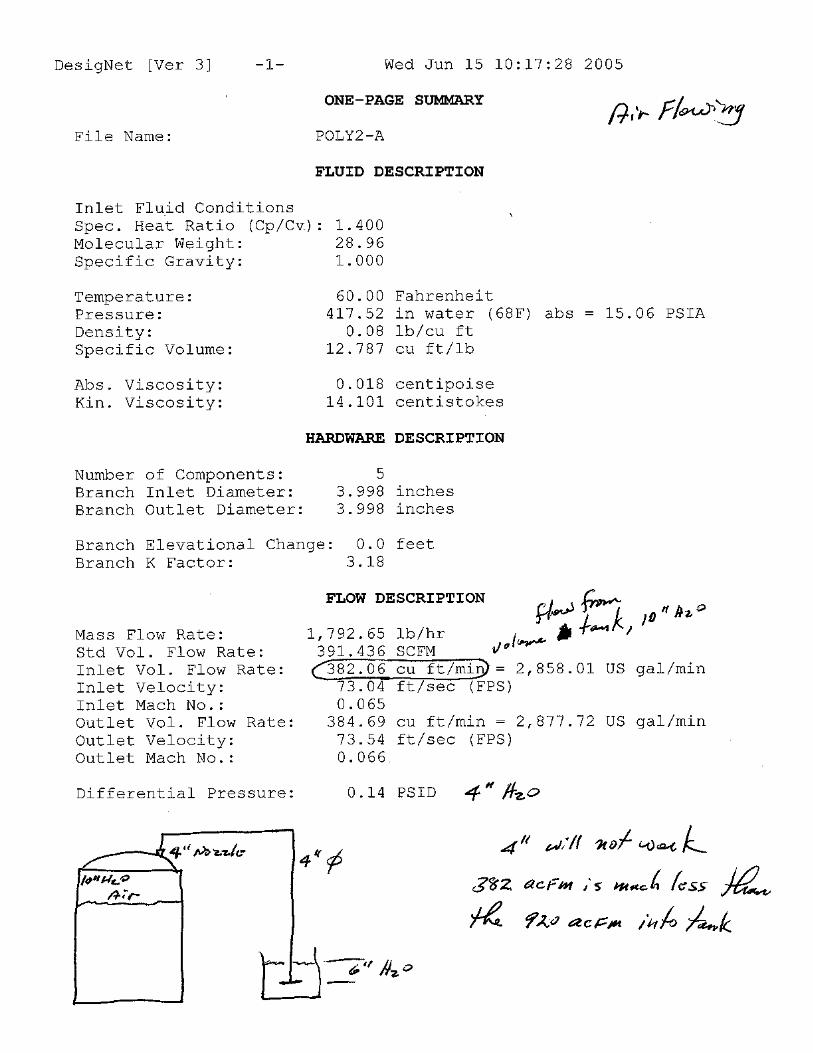
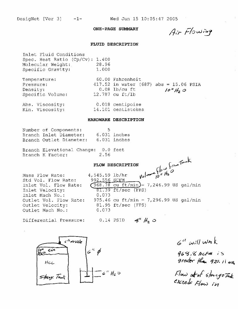
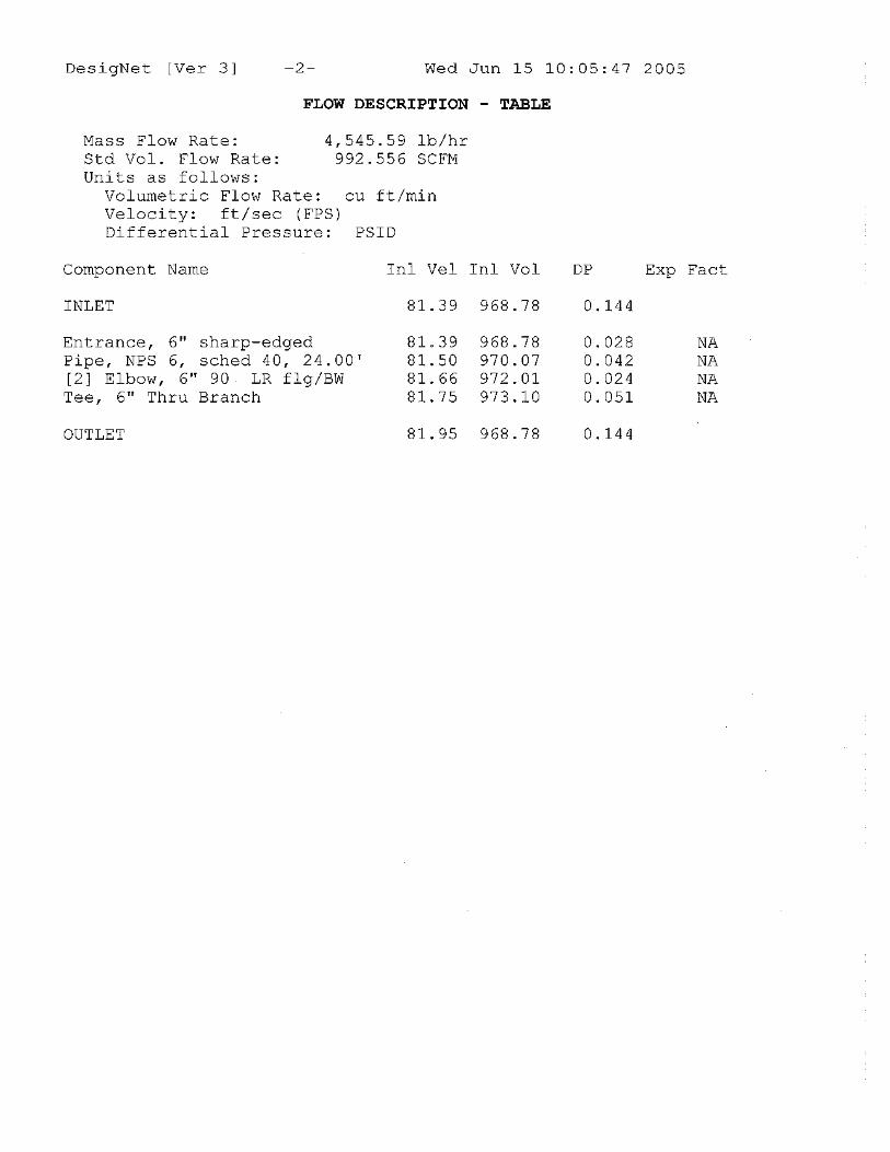
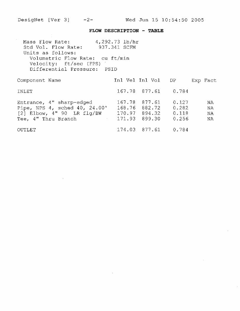
Methodology of the calculation is to determine the actual flow in cubic feet per minute through Section 1 of the system with liquid HCL and with air as the flowing medium in a 2” diameter hose and fill lines. The pressure in the storage tank for both HCL and air can be considered to be 10 inches of water column as this is the rated pressure for the tank. Pressure in the truck trailer is 30 psig determined by the setting on the relief valve. Normal operating procedure is to be a few psi below the maximum, but for calculation purposes it is necessary to use the maximum. The cubic feet per minute determined in Section 1 is then the flow rate which must pass out of the storage tank vent without causing the pressure in the tank to “grow” beyond 10” w.c. There is a back pressure of 6” w.c. at the exit of the vent (seal pot) due to the height of the water. The total motive pressure for the vent is 10 inches w.c. minus 6” w.c. That delta pressure is only 4 inches w.c. (0.144 psi). Results for the Section 1 calculations show that the following flow rates in cubic feet per minute are achieved from the truck to the storage tank with a motive force of 30 psi – 10” w.c. (0.361 psi) = 29.639 psi. HCL 2”dia fill line ----------- 28.8 cfm Air 2”dia fill line ----------- 920 cfm Section 2 then must achieve vent flow rates equal to or better than those flow rates with a pressure differential of only 0.144 psi. The calculated results for Section 2 flowing air and HCL vapor are as follows: Vapor 4”dia vent line ----------- 382 cfm 6” dia vent line ---------- 968.8 cfm This shows that the 4” vent is more than adequate for air pressure driving liquid HCL through the fill line. As long as there is total assurance that the unloading valve at the truck is closed before the truck is totally emptied, there would not be any problem with over pressurizing the Storage Tank. Resistance to flow due to the viscosity of the liquid HCL is sufficient to prevent a rapid displacement of the air inside the storage tank. If, however, the valve at the truck is not closed before air enters the fill line, there will be a very rapid increase of the flow rate into the Storage Tank. The truck will have become a very large air receiver filled with 30 psig air. This air will rush through the fill line into the Storage Tank at the rate shown above of 920 cfm. That air will start leaving the
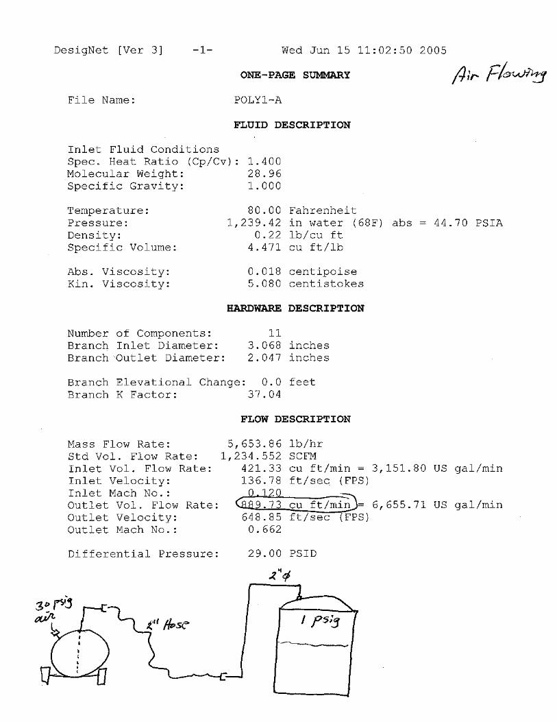
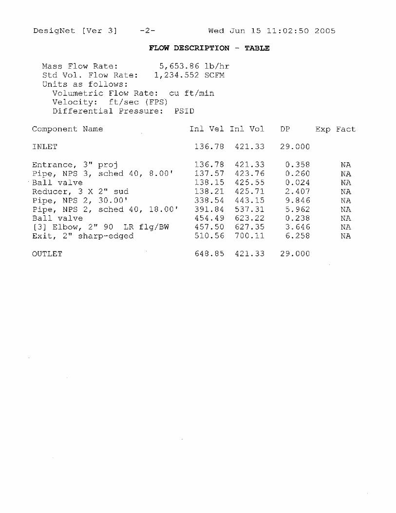
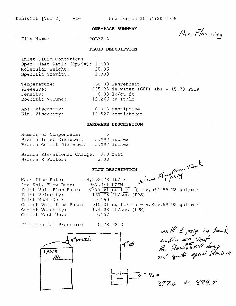
Tank at 382 cfm (4” dia vent) or 969 cfm (6” dia. vent) at the Tank’s maximum pressure of 10 inches w.c. With the 4” vent, pressure will then continue to build until equilibrium of flow is achieved or until the Tank fails. Calculations were made with 1 psig in the tank which showed that air would enter the tank at 890 cfm and would vent out of the tank at 878 cfm. Equilibrium would be established at slightly over 1.0 psig in the Tank (by extrapolation). This is also roughly at the failure point of the tank. Clearly, a 4 inch vent is not adequate. As an example of how quickly a tank failure could happen, let's look at the case of a truck being emptied with a 2" line and hose to the Storage Tank and a 4" vent line to the water seal (scrubber). We can assume that the truck completely unloaded the typical capacity of 5,500 gallons. The Tank has a total volume of 7,275 gallons counting the dome. Tank air space = (7,275 gallons – 5,500 gallons) / 7.48 gal/cu.ft. = 237 cu.ft. From the previous calculations we know that an average flow rate of around 900 cfm would be achieved as the tank went from a few inches of water column to 1.0 psig internal pressure. Flow out through the 4” vent will vary from around 200 cfm immediately after air starts flowing to 878 at 1 psig. Using 550 cfm as the average vent flow, we have the tank being filled with 1 psig air at a rate of 350 cfm (900 – 550) into a space of 237 cu. ft. total. This indicates that the tank would reach 1 psig in less than 1 minute after air starts flowing through the fill line. (This approach to determining time to reach pressure is greatly simplified and certainly not mathematically rigorous, but it is sufficient to see that it would be a very short time before tank failure could potentially occur.) That time would be significantly shortened if the tank was more than 3/4 full, thus reducing the available air space. Also we know that if a 3" fill hose were used instead of a 2" hose, the time before failure would again be shortened. Conclusion: Unless secondary safety devices are in place to protect the Storage Tank from an internal pressure above 10” w.c., it would not be prudent to use a vent smaller than 6" diameter when unloading a tank truck using 30 psig air as the motive force. The margin of error is so small to protect the tank with only 10” w.c. internal pressure rating that a safety relief device, such as a weighted hinged lid on the tank, is strongly recommended.
APPENDIX A
CALCULATIONS

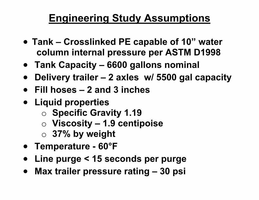
Engineering Study Assumptions • Tank – Crosslinked PE capable of 10” water
column internal pressure per ASTM D1998 • Tank Capacity – 6600 gallons nominal • Delivery trailer – 2 axles w/ 5500 gal capacity • Fill hoses – 2 and 3 inches • Liquid properties
o Specific Gravity 1.19 o Viscosity – 1.9 centipoise o 37% by weight
• Temperature - 60°F • Line purge < 15 seconds per purge • Max trailer pressure rating – 30 psi
![Test & Balance Seminar for CxAs, Engineers, & TAB ... · • Take traverse measurements at actual conditions and actual cubic feet per minute [ACFM (l/s)]. Correct ACFM (l/s) to standard](https://static.fdocuments.us/doc/165x107/607ec5142c83d66907502541/test-balance-seminar-for-cxas-engineers-tab-a-take-traverse.jpg)