ventily pro řízení tlaku yuken - SEALL s.r.o. - hydraulické, … · · 2014-11-3006 :...
74
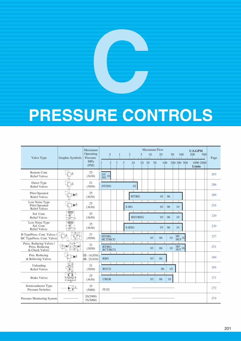
25 (3630) 21 (3050) 25 (3630) 25 (3630) 25 (3630) 25 (3630) 21 (3050) 21 (3050) 25 (3630) 21 (3050) 35 (5080) 20(2900) 35(5080) T Maximum Flow 1 2 5 3 10 20 30 50 100 200 300 500 1000 2000 U.S.GPM .5 1 2 5 20 10 50 100 200 500 L/min Valve Type Maximum Operating Pressure Graphic Symbols MPa (PSI) Remote Cont. Relief Valves Direct Type Relief Valves Pilot Operated Relief Valves Low Noise Type Pilot Operated Relief Valves Brake Valves Unloading Relief Valves Semiconductor Type Pressure Switches Pressure Monitoring System Low Noise Type Sol. Cont. Relief Valves H TypePress. Cont. Valves / HC TypePress. Cont. Valves Page Sol. Cont. Relief Valves Press. Reducing Valves / Press. Reducing & Check Valves Pres. Reducing & Relieving Valves 03 : 14(2030) 06 : 25(3630) 203 206 209 216 220 230 237 251 271 265 272 274 260 10 06 10 06 03 03 10 06 10 06 RT/RG RCT/RCG 10 06 06 10 06 BUCG 10 06 JT-02 RF 16 RCF HF HCF 16 DT DT/DG BT/BG 02 01 DG S-BG 10 06 03 S-BSG BST/BSG HT/HG HCT/HCG 03 03 03 03 03 RBG UBGR C PRESSURE CONTROLS 201
Transcript of ventily pro řízení tlaku yuken - SEALL s.r.o. - hydraulické, … · · 2014-11-3006 :...
25
(3630)
21
(3050)
25
(3630)
25
(3630)
25
(3630)
25
(3630)
21
(3050)
21
(3050)
25
(3630)
21
(3050)
35
(5080)
20(2900)
35(5080)
T
Maximum Flow
1 2 53 10 20 30 50 100 200 300 500 1000 2000
U.S.GPM.5 1 2 5 2010 50 100 200 500
L/min
Valve Type
MaximumOperating
Pressure Graphic SymbolsMPa
(PSI)
Remote Cont.
Relief Valves
Direct Type
Relief Valves
Pilot Operated
Relief Valves
Low Noise TypePilot OperatedRelief Valves
Brake Valves
Unloading
Relief Valves
Semiconductor Type
Pressure Switches
Pressure Monitoring System
Low Noise TypeSol. Cont.
Relief Valves
H TypePress. Cont. Valves /
HC TypePress. Cont. Valves
Page
Sol. Cont.
Relief Valves
Press. Reducing Valves /Press. Reducing& Check Valves
Pres. Reducing
& Relieving Valves 03 : 14(2030)
06 : 25(3630)
203
206
209
216
220
230
237
251
271
265
272
274
260
1006
1006
03
03
1006
1006
RT/RG RCT/RCG
1006
06
1006
BUCG 1006
JT-02
RF 16
RCF
HFHCF
16
DT
DT/DG
BT/BG
02
01 DG
S-BG
100603S-BSG
BST/BSG
HT/HGHCT/HCG
03
03
03
03
03
RBG
UBGR
CPRESSURE CONTROLS
201
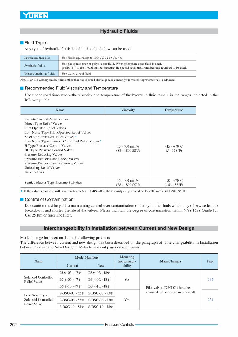
Name Viscosity
15 - 400 mm2/s
(88 - 1800 SSU)
Temperature
-15 - +70°C
(5 - 158°F)
15 - 400 mm2/s
(88 - 1800 SSU)
-20 - +70°C
(- 4 - 158°F)
Recommended Fluid Viscosity and Temperature
Control of Contamination
Hydraulic Fluids
Due caution must be paid to maintaining control over contamination of the hydraulic fluids which may otherwise lead to
breakdowns and shorten the life of the valves. Please maintain the degree of contamination within NAS 1638-Grade 12.
Use 25 µm or finer line filter.
Use under conditions where the viscosity and temperature of the hydraulic fluid remain in the ranges indicated in the
following table.
Remote Control Relief Valves
Direct Type Relief Valves
Pilot Operated Relief Valves
Low Noise Type Pilot Operated Relief Valves
Solenoid Controlled Relief Valves
Low Noise Type Solenoid Controlled Relief Valves
H Type Pressure Control Valves
HC Type Pressure Control Valves
Pressure Reducing Valves
Pressure Reducing and Check Valves
Pressure Reducing and Relieving Valves
Unloading Relief Valves
Brake Valves
Semiconductor Type Pressure Switches
Petroleum base oils
Synthetic fluids
Water containing fluids
Use fluids equivalent to ISO VG 32 or VG 46.
Use phosphate ester or polyol ester fluid. When phosphate ester fluid is used,
prefix "F-" to the model number because the special seals (fluororubber) are required to be used.
Use water-glycol fluid.
Fluid Types
Any type of hydraulic fluids listed in the table below can be used.
Note: For use with hydraulic fluids other than those listed above, please consult your Yuken representatives in advance.
If the valve is provided with a vent ristrictor (ex. : A-BSG-03), the viscosity range should be 15 - 200 mm2/s (80 - 900 SSU).
Solenoid Controlled
Relief Valve
Low Noise Type
Solenoid Controlled
Relief Valve
Current
Model Numbers
New
Mounting
Interchange-
ability
Yes
Yes
231
222
Main Changes PageName
BS*-03, -48*BS*-03, -47*BS*-06, -48*BS*-06, -47*BS*-10, -48*BS*-10, -47*S-BSG-03, -53*S-BSG-03, -52*S-BSG-06, -53*S-BSG-06, -52*S-BSG-10, -53*S-BSG-10, -52*
Pilot valves (DSG-01) have been
changed in the design numbers 70.
Interchangeability in Installation between Current and New Design
Model change has been made on the following products.
The difference between current and new design has been described on the paragraph of “Interchangeability in Installation
between Current and New Design”. Refer to relevant pages on each series.
Pressure Controls202
203
PRESSURE CONTROLS
Rem
ote
Co
ntr
ol
Relief
Valv
es
C
Remote Control Relief Valves
Model Numbers
Threaded
Connection
Sub-plate
Mounting
Max. Operating Pres.
MPa (PSI)
Approx. Mass
kg (lbs.)
DT type DG type
1.6 (3.5) 1.4 (3.1)25 (3630)DG-01-22*DT-01-22*
Series Number
F:
Special Seals for Phosphate Ester Type Fluids (Omit if not required)
Special Seals
F-
22
D
D:
Remote Control Relief Valves
22
01
T: Threaded Connection
G:Sub-plate Mounting
TType of
MountingValve Size
Design
NumberDesign Standards
-22 *-01
None: Japanese Std. "JIS"
80: European Design Std.
90: N. American Design Std.
None: Japanese Std. "JIS" and
European Design Std.
90: N. American Design Std.
Valve Model
Numbers
Socket Head Cap Screw
Approx.
Mass
kg (lbs.)
Japanese Std. "JIS" and European Design Std. N. American Design Std.
DG-01 No.10-24 UNC 1-3/4 Lg. 4M5 45 Lg.
Qty.
Valve Model
Numbers
DG-01
Japanese Standard "JIS" European Design Standard N. American Design Standard
Sub-plate
Model Numbers
Thread
Size
Sub-plate
Model Numbers
Thread
Size
Sub-plate
Model Numbers
Thread
Size
DGM-02-20 Rc 1/4 DGM-02-2080 1/4 BSP.F DGM-02-2090 1/4 NPT 0.7 (1.5)
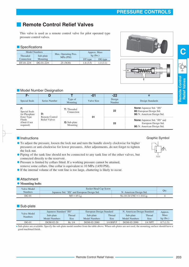
Specifications
Model Number Designation
Instructions
Sub-plate
Mounting bolts
Attachment
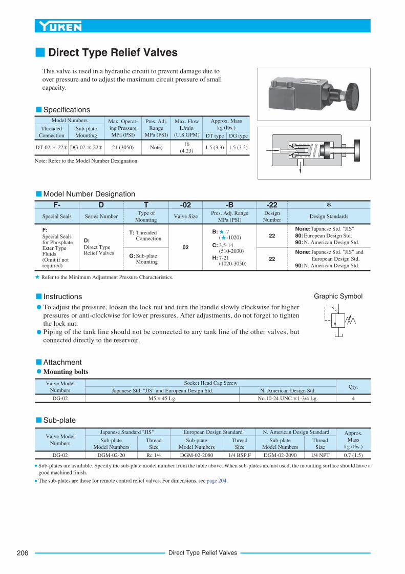
Graphic Symbol
Remote Control Relief Valves
This valve is used as a remote control valve for pilot operated type
pressure control valves.
To adjust the pressure, loosen the lock nut and turn the handle slowly clockwise for higher
pressures or anti-clockwise for lower pressures. After adjustments, do not forget to tighten
the lock nut.
Piping of the tank line should not be connected to any tank line of the other valves, but
connected directly to the reservoir.
Pressure is limited by collars fitted. If a working pressure cannot be attained,
remove some collars. One collar is equivalent to 10 MPa (1450 PSI).
If the internal volume of the vent line is too large, chattering is likely to occur.
Sub-plates are available. Specify the sub-plate model number from the table above. When sub-plates are not used, the mounting surface should have a
good machined finish.
Remote Control Relief Valves204
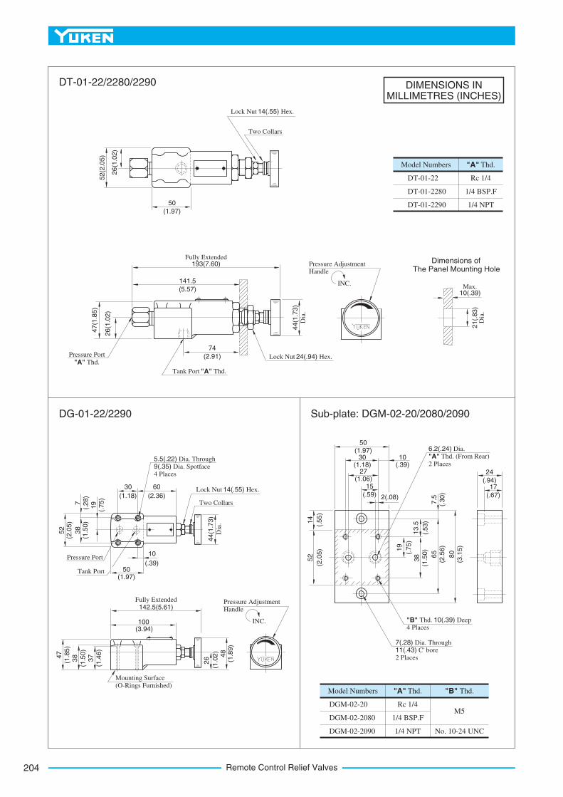
DIMENSIONS INMILLIMETRES (INCHES)
Model Numbers
DT-01-22
DT-01-2280
DT-01-2290
"A" Thd.
Rc 1/4
1/4 BSP.F
1/4 NPT
Model Numbers
DGM-02-20
DGM-02-2080
DGM-02-2090
"A" Thd.
Rc 1/4
1/4 BSP.F
1/4 NPT
"B" Thd.
M5
No. 10-24 UNC
Lock Nut 14(.55) Hex.
Two Collars
(1.97)
50
26(1
.02)
52(2
.05)
193(7.60)Fully Extended
(5.57)
141.5
(2.91)
74Pressure Port
"A" Thd.
Tank Port "A" Thd.
Lock Nut 24(.94) Hex.
47(1
.85)
26(1
.02)
44(1
.73)
Dia
.
INC.
Pressure Adjustment Handle
21(.
83)
Dia
.
10(.39)Max.
(.67)
17(.94)
24
(1.97)50
(1.18)30
(.39)10
(1.06)27
(.59)
15
2(.08)
7.5
(.30)
13.5
(.53)
19
(.75)
38
(1.5
0)
65
(2.5
6)
80
(3.1
5)
52
(2.0
5)
14
(.55)
6.2(.24) Dia.
"A" Thd. (From Rear)
2 Places
7(.28) Dia. Through 11(.43) C' bore 2 Places
"B" Thd. 10(.39) Deep 4 Places
Lock Nut 14(.55) Hex.
Two Collars(1.18)
30
(2.36)
60
44(1
.73)
Dia
.
52
(2.0
5)
38
(1.5
0)
19
(1.97)50
10
(.39)
142.5(5.61)Fully Extended
(3.94)100
47
(1.8
5)
38
(1.5
0)
37
(1.4
6)
Mounting Surface (O-Rings Furnished)
26
(1.0
2)
48
(1.8
9)
INC.
Pressure Adjustment Handle
Pressure Port
5.5(.22) Dia. Through 9(.35) Dia. Spotface 4 Places
(.75)
7(.
28)
DT-01-22/2280/2290
DG-01-22/2290 Sub-plate: DGM-02-20/2080/2090
Dimensions of The Panel Mounting Hole
Tank Port
205
PRESSURE CONTROLS
Rem
ote
Co
ntr
ol
Relief
Valv
es
C
Remote Control Relief Valves
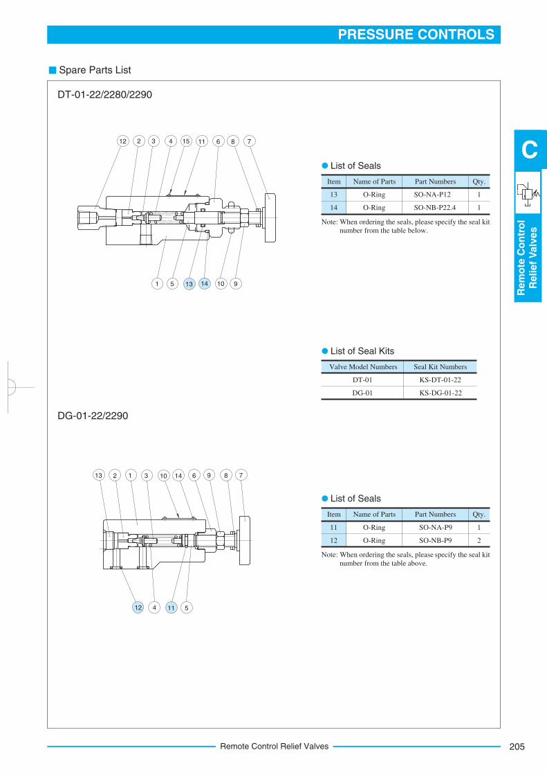
Spare Parts List
Item
SO-NA-P12
SO-NB-P22.4
Name of Parts Qty.
13
14
O-Ring
O-Ring
1
1
Part Numbers
Item
SO-NA-P9
SO-NB-P9
Name of Parts Qty.
11
12
O-Ring
O-Ring
1
2
Part Numbers
KS-DT-01-22
KS-DG-01-22
Valve Model Numbers
DT-01
DG-01
Seal Kit Numbers
4 5
13 2 1 3 10 14 6 9 8 7
51 10 9
12 2 3 4 15 11 6 8 7
List of Seals
Note: When ordering the seals, please specify the seal kit
number from the table below.
List of Seals
Note:
List of Seal Kits
DT-01-22/2280/2290
DG-01-22/2290
When ordering the seals, please specify the seal kit
number from the table above.
13 14
12 11
Direct Type Relief Valves206
Specifications
Model Number Designation
Instructions
Sub-plate
Mounting bolts
Attachment
Graphic Symbol
Direct Type Relief Valves
This valve is used in a hydraulic circuit to prevent damage due to
over pressure and to adjust the maximum circuit pressure of small
capacity.
To adjust the pressure, loosen the lock nut and turn the handle slowly clockwise for higher
pressures or anti-clockwise for lower pressures. After adjustments, do not forget to tighten
the lock nut.
Piping of the tank line should not be connected to any tank line of the other valves, but
connected directly to the reservoir.
Model Numbers
Threaded
Connection
Sub-plate
Mounting
Max. Operat-
ing Pressure
MPa (PSI)
Approx. Mass
kg (lbs.)
DT type DG type
16
(4.23)1.5 (3.3)21 (3050)DT-02-*-22*
Pres. Adj.
Range
MPa (PSI)
Max. Flow
L/min
(U.S.GPM)
DG-02-*-22* Note) 1.5 (3.3)
Note: Refer to the Model Number Designation.
Series Number
F:
Special Seals for Phosphate Ester Type Fluids (Omit if not required)
Special Seals
F-
22
D
D:
Direct Type Relief Valves
22
02
T: Threaded Connection
G:Sub-plate Mounting
TType of
MountingValve Size
Pres. Adj. Range
MPa (PSI)Design Standards
-B *-02
None: Japanese Std. "JIS"
80: European Design Std.
90: N. American Design Std.
None: Japanese Std. "JIS" and
European Design Std.
90: N. American Design Std.
-22Design
Number
C:
B: -7 ( -1020)
H:
3.5-14 (510-2030)
7-21 (1020-3050)
Valve Model
Numbers
Socket Head Cap Screw
Japanese Std. "JIS" and European Design Std. N. American Design Std.
DG-02 4M5 45 Lg.
Qty.
Approx.
Mass
kg (lbs.)
Valve Model
Numbers
DG-02
Japanese Standard "JIS" European Design Standard N. American Design Standard
Sub-plate
Model Numbers
Thread
Size
Sub-plate
Model Numbers
Thread
Size
Sub-plate
Model Numbers
Thread
Size
DGM-02-20 Rc 1/4 DGM-02-2080 1/4 BSP.F DGM-02-2090 1/4 NPT 0.7 (1.5)
Refer to the Minimum Adjustment Pressure Characteristics.
Sub-plates are available. Specify the sub-plate model number from the table above. When sub-plates are not used, the mounting surface should have a
good machined finish.
The sub-plates are those for remote control relief valves. For dimensions, see page 204.
No.10-24 UNC 1-3/4 Lg.
207
PRESSURE CONTROLS
Dir
ect
Typ
eR
elief
Valv
es
C
Direct Type Relief Valves
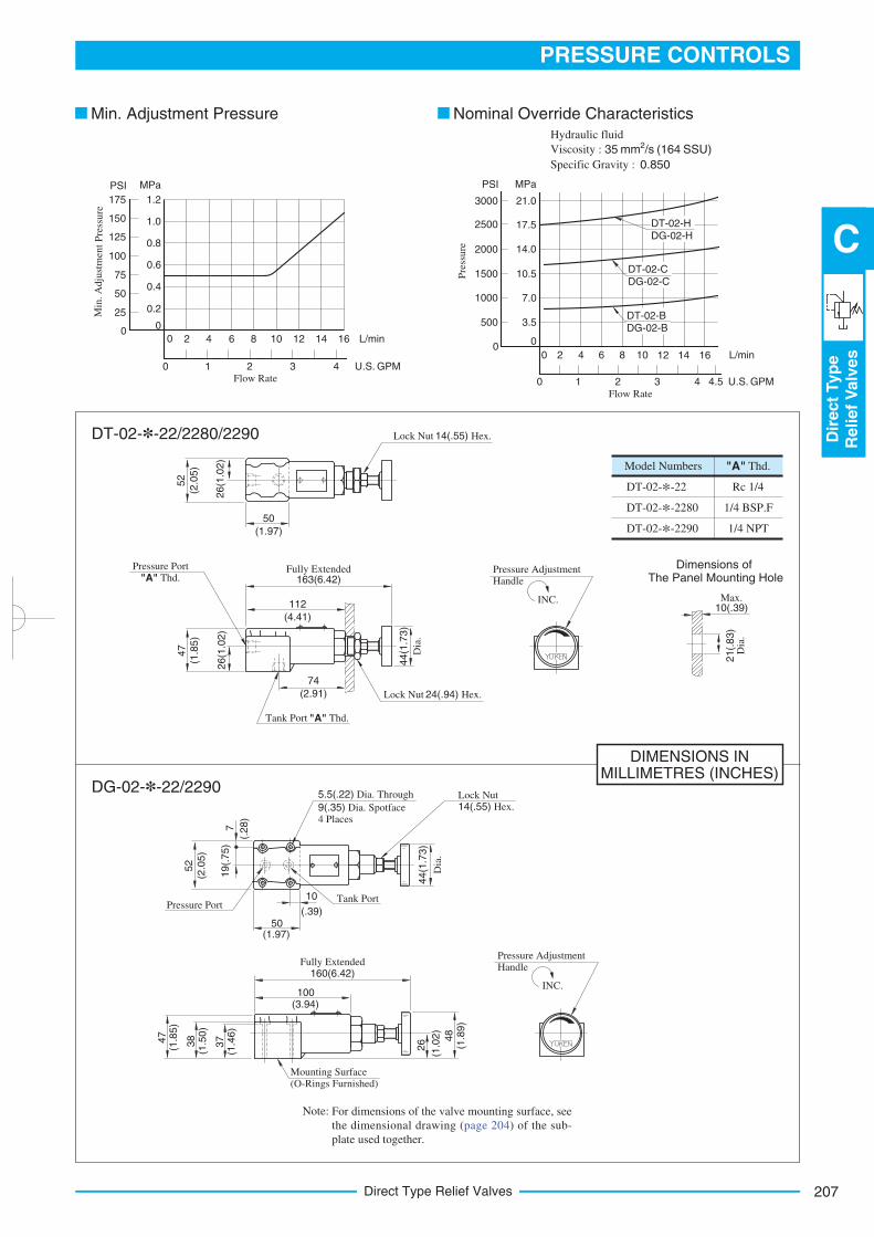
DIMENSIONS INMILLIMETRES (INCHES)
Model Numbers
DT-02-*-22
DT-02-*-2280
DT-02-*-2290
"A" Thd.
Rc 1/4
1/4 BSP.F
1/4 NPT
52
26(1
.02)
(2.0
5)
(1.97)
50
Lock Nut 14(.55) Hex.
47
26(1
.02)
(1.8
5)
163(6.42)Fully Extended
(4.41)
112
Pressure Port
"A" Thd.
Tank Port "A" Thd.
(2.91)
74
Lock Nut 24(.94) Hex.
44(1
.73)
Dia
.
INC.
Pressure Adjustment Handle
21(.
83)
Dia
.
10(.39)Max.
INC.
Pressure Adjustment Handle
52
(2.0
5)
19(.
75)
7
Pressure Port
Lock Nut 14(.55) Hex.
Tank Port
44(1
.73)
Dia
.
10
(.39)
5.5(.22) Dia. Through
9(.35) Dia. Spotface 4 Places
(1.97)50
160(6.42)Fully Extended
(3.94)100
26
(1.0
2)
48
(1.8
9)
38
(1.5
0)
47
(1.8
5)
Mounting Surface (O-Rings Furnished)
(.28)
DT-02-B DG-02-B
DT-02-C DG-02-C
DT-02-H DG-02-H
3000
PSI
14.0
10.5
7.0
3.5
0
MPa
0 2 L/min
0 1 2 3 4 U.S. GPMFlow Rate
Flow Rate
Pre
ssure
4 8 106 12 14 16
4.5
17.5
21.0
2500
2000
1500
1000
500
0 2 L/min
0 3 4 U.S. GPM
4 8 106 12 14 16
21
0.8
0.6
0.4
0.2
0
MPa
1.0
1.2
0
175
PSI
Min
.A
dju
stm
en
tP
res s
ure
125
100
75
50
25
0
150
Min. Adjustment Pressure Nominal Override Characteristics
DG-02-*-22/2290
DT-02-*-22/2280/2290
Note:
Dimensions of The Panel Mounting Hole
Hydraulic fluid
Viscosity : 2 35 mm /s (164 SSU)
Specific Gravity : 0.850
37
(1.4
6)
For dimensions of the valve mounting surface, see
the dimensional drawing (page 204) of the sub-
plate used together.
Direct Type Relief Valves208
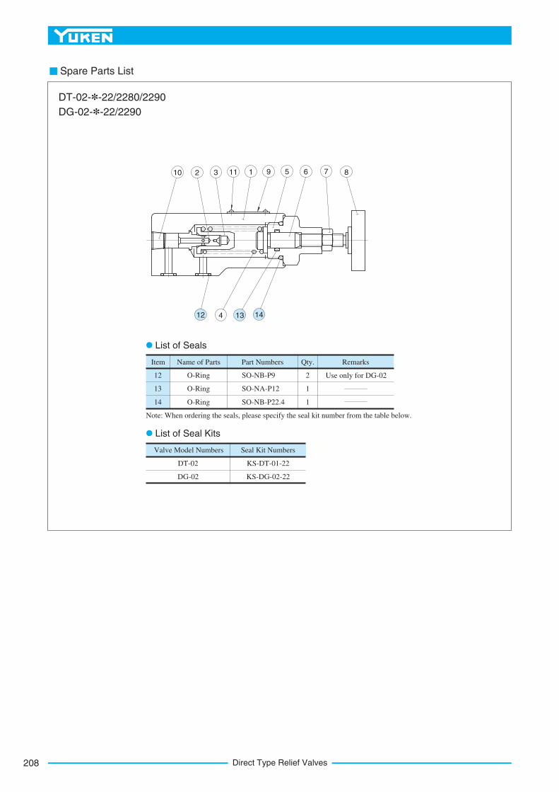
Spare Parts List
Name of Parts Part Numbers Qty. Remarks
Use only for DG-022
1
1
O-Ring
O-Ring
O-Ring
12
13
14
SO-NB-P9
SO-NA-P12
SO-NB-P22.4
Item
Valve Model Numbers Seal Kit Numbers
KS-DT-01-22
KS-DG-02-22
DT-02
DG-02
10 2 3 11 1 9 5 6 7 8
4
List of Seals
List of Seal Kits
Note: When ordering the seals, please specify the seal kit number from the table below.
DT-02-*-22/2280/2290
DG-02-*-22/2290
12 13 14
209
PRESSURE CONTROLS
Pilo
tO
pera
ted
Relief
Valv
es
C
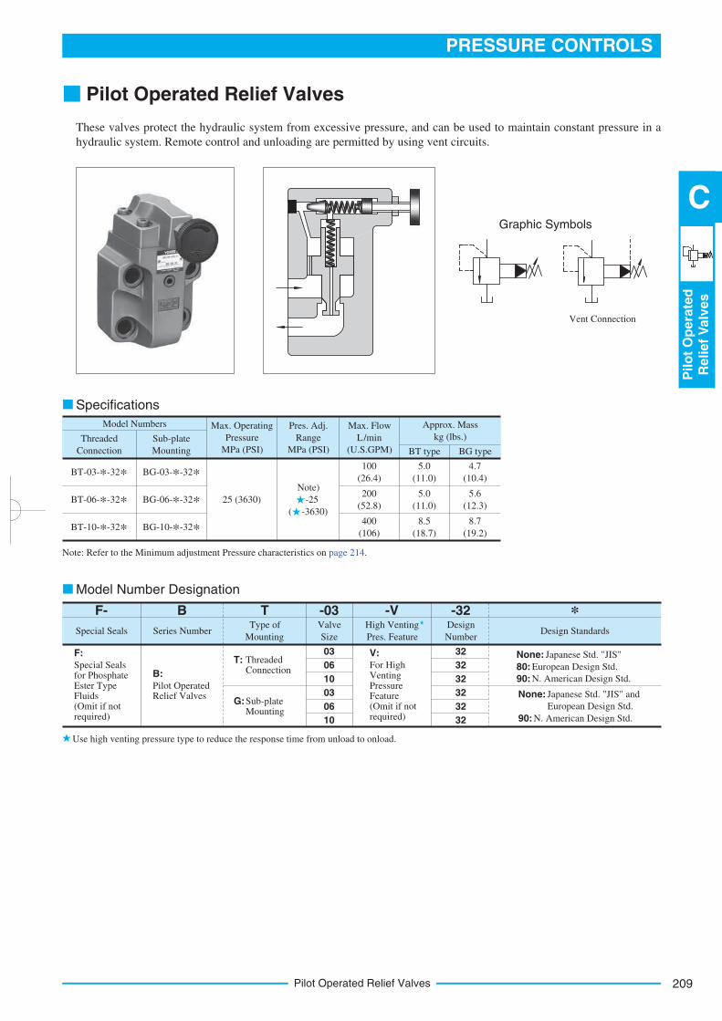
Pilot Operated Relief Valves
Pilot Operated Relief Valves
These valves protect the hydraulic system from excessive pressure, and can be used to maintain constant pressure in a
hydraulic system. Remote control and unloading are permitted by using vent circuits.
Model Numbers
Threaded
Connection
Sub-plate
Mounting
Max. Operating
Pressure
MPa (PSI)
Approx. Mass
kg (lbs.)
BT type BG type
5.0
(11.0)
Pres. Adj.
Range
MPa (PSI)
Max. Flow
L/min
(U.S.GPM)
BT-03-*-32* BG-03-*-32*4.7
(10.4)
5.0
(11.0)
5.6
(12.3)
8.5
(18.7)
8.7
(19.2)
100
(26.4)
200
(52.8)
400
(106)
BT-06-*-32* BG-06-*-32*
BT-10-*-32* BG-10-*-32*
25 (3630)
Note)
-25
( -3630)
Series Number
F:
Special Seals for Phosphate Ester Type Fluids (Omit if not required)
Special Seals
F-
32
32
32
32
32
32
B
B:
Pilot Operated Relief Valves
T: Threaded Connection
G:Sub-plate Mounting
TType of
Mounting
Valve
Size
High Venting
Pres. FeatureDesign Standards
-V *-03
None: Japanese Std. "JIS"
80: European Design Std.
90: N. American Design Std.
None: Japanese Std. "JIS" and
European Design Std.
90: N. American Design Std.
-32Design
Number
03
06
10
03
06
10
V:
For High Venting Pressure Feature (Omit if not required)
Specifications
Note: Refer to the Minimum adjustment Pressure characteristics on page 214.
Use high venting pressure type to reduce the response time from unload to onload.
Graphic Symbols
Vent Connection
Model Number Designation
Pilot Operated Relief Valves210
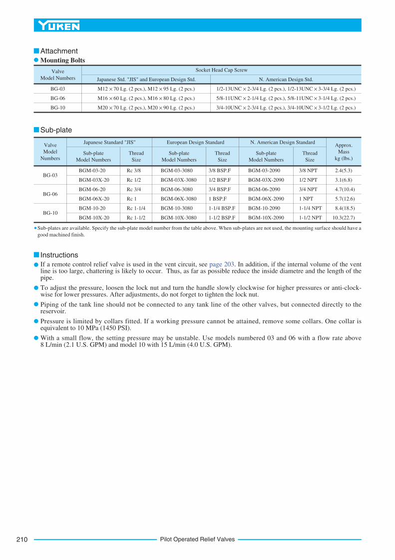
Valve
Model Numbers Japanese Std. "JIS" and European Design Std. N. American Design Std.
Socket Head Cap Screw
BG-03
BG-06
BG-10
M12 70 Lg. (2 pcs.), M12 95 Lg. (2 pcs.)
M16 60 Lg. (2 pcs.), M16 80 Lg. (2 pcs.)
M20 70 Lg. (2 pcs.), M20 90 Lg. (2 pcs.)
1/2-13UNC 2-3/4 Lg. (2 pcs.), 1/2-13UNC 3-3/4 Lg. (2 pcs.)
5/8-11UNC 2-1/4 Lg. (2 pcs.), 5/8-11UNC 3-1/4 Lg. (2 pcs.)
3/4-10UNC 2-3/4 Lg. (2 pcs.), 3/4-10UNC 3-1/2 Lg. (2 pcs.)
Valve
Model
Numbers
Japanese Standard "JIS" European Design Standard N. American Design StandardApprox.
Mass
kg (lbs.)Sub-plate
Model Numbers
Thread
Size
Sub-plate
Model Numbers
Thread
Size
Sub-plate
Model Numbers
Thread
Size
BG-03
BG-06
BG-10
BGM-03-20
BGM-03X-20
BGM-06-20
BGM-06X-20
BGM-10-20
BGM-10X-20
Rc 3/8
Rc 1/2
Rc 3/4
Rc 1
Rc 1-1/4
Rc 1-1/2
BGM-03-3080
BGM-03X-3080
BGM-06-3080
BGM-06X-3080
BGM-10-3080
BGM-10X-3080
3/8 BSP.F
1/2 BSP.F
3/4 BSP.F
1 BSP.F
1-1/4 BSP.F
1-1/2 BSP.F
BGM-03-2090
BGM-03X-2090
BGM-06-2090
BGM-06X-2090
BGM-10-2090
BGM-10X-2090
3/8 NPT
1/2 NPT
3/4 NPT
1 NPT
1-1/4 NPT
1-1/2 NPT
2.4
3.1
4.7
5.7
8.4
10.3
(5.3)
(6.8)
(10.4)
(12.6)
(18.5)
(22.7)
Attachment
Mounting Bolts
Instructions
Sub-plate
Sub-plates are available. Specify the sub-plate model number from the table above. When sub-plates are not used, the mounting surface should have a
good machined finish.
If a remote control relief valve is used in the vent circuit, see page 203. In addition, if the internal volume of the vent line is too large, chattering is likely to occur. Thus, as far as possible reduce the inside diametre and the length of the pipe.
To adjust the pressure, loosen the lock nut and turn the handle slowly clockwise for higher pressures or anti-clock-wise for lower pressures. After adjustments, do not forget to tighten the lock nut.
Piping of the tank line should not be connected to any tank line of the other valves, but connected directly to the reservoir.
Pressure is limited by collars fitted. If a working pressure cannot be attained, remove some collars. One collar is equivalent to 10 MPa (1450 PSI).
With a small flow, the setting pressure may be unstable. Use models numbered 03 and 06 with a flow rate above 8 L/min (2.1 U.S. GPM) and model 10 with 15 L/min (4.0 U.S. GPM).
211
PRESSURE CONTROLS
Pilo
tO
pera
ted
Relief
Valv
es
C
Pilot Operated Relief Valves
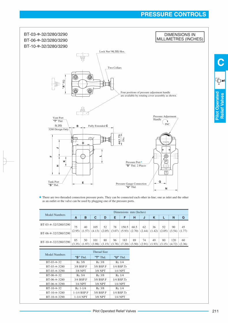
DIMENSIONS INMILLIMETRES (INCHES)
Model NumbersDimensions mm (Inches)
A
BT-03-*-32/3280/3290
BT-06-*-32/3280/3290
BT-10-*-32/3280/3290
75
(2.95)
B C D E F H J K L N Q
40
(1.57)
105
(4.13)
52
(2.05)
78
(3.07)
150.5
(5.93)
68.5
(2.70)
62
(2.44)
36
(1.42)
52
(2.05)
90
(3.54)
45
(1.77)
85
(3.35)
50
(1.97)
101
(3.98)
80
(3.15)
96
(3.78)
183
(7.20)
89
(3.50)
74
(2.91)
80
(3.15)
120
(4.72)
49
(1.93)
60
(2.36)
Model Numbers
BT-03-*-32
BT-03-*-3280
BT-03-*-3290
BT-06-*-32
BT-06-*-3280
BT-06-*-3290
BT-10-*-32
BT-10-*-3280
BT-10-*-3290
Thread Size
"S" Thd. "T" Thd. "U" Thd.
Rc 3/8
3/8 BSP.F
3/8 NPT
Rc 3/4
3/4 BSP.F
3/4 NPT
Rc 1-1/4
1-1/4 BSP.F
1-1/4 NPT
Rc 3/8
3/8 BSP.F
3/8 NPT
Rc 3/8
3/8 BSP.F
3/8 NPT
Rc 3/8
3/8 BSP.F
3/8 NPT
Rc 1/4
1/4 BSP.Tr
1/4 NPT
Rc 1/4
1/4 BSP.Tr
1/4 NPT
Rc 1/4
1/4 BSP.Tr
1/4 NPT
Lock Nut 14(.55) Hex.
"A"
SQ
.
Two Collars
Four positions of pressure adjustment handle
are available by rotating cover assembly as shown.
Fully Extended CBINC.
Pressure Adjustment Handle
D 44(1
.73)
Dia
.
5(.20)
3280 Design Only
F
JH
K
L
E Q
N
T
P
Pressure Gauge Connection
"U" Thd.
Pressure Port
"S" Thd. 2 Places
Tank Port
"S" Thd.
Vent Port
"T" Thd.
BT-03-*-32/3280/3290
BT-06-*-32/3280/3290
BT-10-*-32/3280/3290
There are two threaded connection pressure ports. They can be connected each other in-line; one as inlet and the other
as an outlet or the valve can be used by plugging one of the pressure ports.
Pilot Operated Relief Valves212
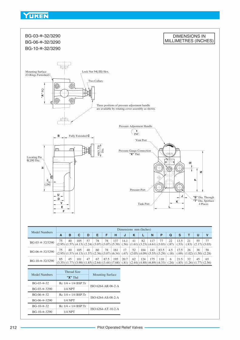
DIMENSIONS INMILLIMETRES (INCHES)
Model Numbers
BG-03-*-32/3290
BG-06-*-32/3290
BG-10-*-32/3290
75 (2.95)
75 (2.95)
85 (3.35)
45 (1.77)
40 (1.57)
40 (1.57)
101 (3.98)
105 (4.13)
105 (4.13)
47 (1.85)
57 (2.24)
40 (1.57)
67 (2.64)
78 (3.07)
60 (2.36)
87.5(3.44)
78 (3.07)
78 (3.07)
195 (7.68)
137 (5.39)
161 (6.34)
20.7 (.81)
14.1 (.56)
17 (.67)
62 (2.44)
41 (1.61)
52 (2.05)
124 (4.88)
82 (3.23)
104 (4.09)
175 (6.89)
117 (4.61)
141 (5.55)
110 (4.33)
77 (3.03)
83.5 (3.29)
6 (.24)
22 (.87)
4.5 (.18)
21.5 (.85)
13.5 (.53)
17.5 (.69)
32 (1.26)
21 (.83)
26 (1.02)
45 (1.77)
55 (2.17)
38 (1.50)
65 (2.56)
77 (3.03)
58 (2.28)
Dimensions mm (Inches)
A B C D E F H J K L N P Q S T U V
Model Numbers
BG-03-*-32
BG-03-*-3290
BG-06-*-32
BG-06-*-3290
BG-10-*-32
BG-10-*-3290
1/4 = 1/4 BSP.Tr
1/4 NPT
1/4 = 1/4 BSP.Tr
1/4 NPT
1/4 = 1/4 BSP.Tr
1/4 NPT
Rc
Rc
Rc
Thread Size
"X" ThdMounting Surface
ISO 6264-AR-06-2-A
ISO 6264-AS-08-2-A
ISO 6264-AT-10-2-A
"S" Dia. Through
"T" Dia. Spotface 4 PlacesTank Port
Pressure Port
Pressure Gauge Connection
"X" Thd.
Vent Port
INC.
Pressure Adjustment Handle
Locating Pin 6(.24) Dia.
Mounting Surface
(O-Rings Furnished)
Lock Nut 14(.55) Hex.
Two Collars
Three positions of pressure adjustment handle
are available by rotating cover assembly as shown.
"A"
SQ
.
B Fully Extended C
44(1
.73)
Dia
.
6
(.24)
U
D
V
E
F
L
K
J
Q
P
N
H
BG-03-*-32/3290
BG-06-*-32/3290
BG-10-*-32/3290
213
PRESSURE CONTROLS
Pilo
tO
pera
ted
Relief
Valv
es
C
Pilot Operated Relief Valves
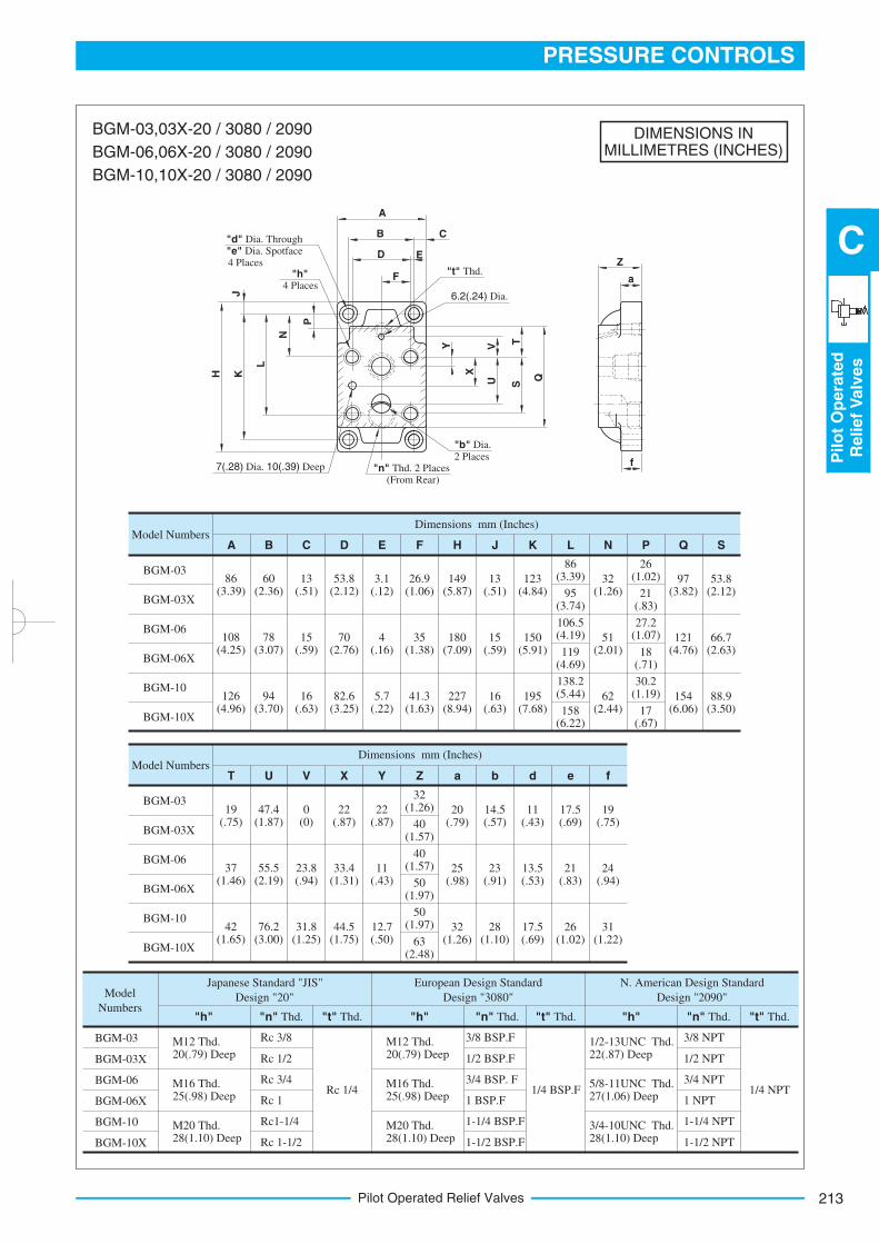
DIMENSIONS INMILLIMETRES (INCHES)
86 (3.39)
Model Numbers
BGM-03
BGM-03X
BGM-06
BGM-06X
BGM-10
BGM-10X
Model Numbers
BGM-03
BGM-03X
BGM-06
BGM-06X
BGM-10
BGM-10X
Dimensions mm (Inches)
A B C D E F H J K L N P Q S
Dimensions mm (Inches)
T U V X Y Z a b d e f
95 (3.74)
106.5 (4.19)
119 (4.69)
138.2 (5.44)
158 (6.22)
26 (1.02)
21 (.83)
27.2 (1.07)
18 (.71)
30.2 (1.19)
17 (.67)
86 (3.39)
108 (4.25)
126 (4.96)
60 (2.36)
78 (3.07)
94 (3.70)
13 (.51)
15 (.59)
16 (.63)
53.8 (2.12)
70 (2.76)
82.6 (3.25)
3.1 (.12)
4 (.16)
5.7 (.22)
26.9 (1.06)
35 (1.38)
41.3 (1.63)
149 (5.87)
180 (7.09)
227 (8.94)
13 (.51)
15 (.59)
16 (.63)
123 (4.84)
150 (5.91)
195 (7.68)
32 (1.26)
51 (2.01)
62 (2.44)
97 (3.82)
121 (4.76)
154 (6.06)
53.8 (2.12)
66.7 (2.63)
88.9 (3.50)
19 (.75)
37 (1.46)
42 (1.65)
47.4 (1.87)
55.5 (2.19)
76.2 (3.00)
0 (0)
23.8 (.94)
31.8 (1.25)
22 (.87)
33.4 (1.31)
44.5 (1.75)
22 (.87)
11 (.43)
12.7 (.50)
32 (1.26)
40 (1.57)
40 (1.57)
50 (1.97)
50 (1.97)
63 (2.48)
14.5 (.57)
23 (.91)
28 (1.10)
11 (.43)
13.5 (.53)
17.5 (.69)
17.5 (.69)
21 (.83)
26 (1.02)
19 (.75)
24 (.94)
31 (1.22)
20 (.79)
25 (.98)
32 (1.26)
Model
Numbers
BGM-03
BGM-03X
BGM-06
BGM-06X
BGM-10
BGM-10X
Japanese Standard "JIS"
Design "20"
European Design Standard
Design "3080"
N. American Design Standard
Design "2090"
"h" "n" Thd. "t" Thd. "h" "n" Thd. "t" Thd. "h" "n" Thd. "t" Thd.
Rc 3/8
Rc 1/2
Rc 3/4
Rc 1
Rc1-1/4
Rc 1-1/2
3/8 BSP.F
1/2 BSP.F
3/4 BSP. F
1 BSP.F
1-1/4 BSP.F
1-1/2 BSP.F
3/8 NPT
1/2 NPT
3/4 NPT
1 NPT
1-1/4 NPT
1-1/2 NPT
Rc 1/4 1/4 BSP.F 1/4 NPT
M12 Thd. 20(.79) Deep
M16 Thd. 25(.98) Deep
M20 Thd. 28(1.10) Deep
M12 Thd. 20(.79) Deep
M16 Thd. 25(.98) Deep
M20 Thd. 28(1.10) Deep
1/2-13UNC Thd. 22(.87) Deep
5/8-11UNC Thd. 27(1.06) Deep
3/4-10UNC Thd. 28(1.10) Deep
Z
a
f
A
B
D
F
C
E
Y V T
X
U S
Q
P
N
L
KH
J"d" Dia. Through
"e" Dia. Spotface 4 Places
"h"4 Places
7(.28) Dia. 10(.39) Deep "n" Thd. 2 Places(From Rear)
"b" Dia.
2 Places
6.2(.24) Dia.
"t" Thd.
BGM-03,03X-20 / 3080 / 2090
BGM-06,06X-20 / 3080 / 2090
BGM-10,10X-20 / 3080 / 2090
Pilot Operated Relief Valves214
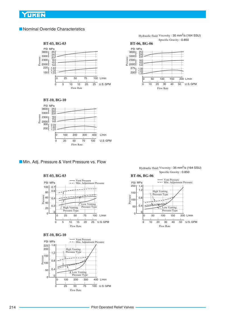
3600
3300
2300
2000
225
150
PSI2524231615141.61.31.0
MPa
0 25 50 75 100 L/min
0 5 10 15 20 25 U.S. GPM
Flow Rate
3600
3300
2300
2000
275
200
PSI252423
161514
1.91.61.3
MPa
0 50 100 150 200 L/min
0 10 20 30 40 50 U.S. GPM
Flow Rate
3600
3300
2300
2000300
200
PSI252423
161514
2.01.61.2
MPa
0 25 50 75 100 U.S. GPM
Flow Rate
0 100 200 300 400 L/min
Pre
ssure
Pre
ssure
Pre
ssure
100
80
60
40
20
0
PSI MPa
0.7
0.6
0.4
0.2
0
0 25 50 75 100 L/min
0 5 10 20 25 U.S. GPM15
Flow Rate
0 50 100 150 200 L/min
0 10 20 40 50 U.S. GPM30
Flow Rate
MPa
1.4
1.2
0.8
0.4
0
200
150
100
50
0
PSI
225
200
150
100
50
0
PSI MPa
1.6
1.2
0.8
0.4
0
0 100 200 300 400 L/min
0 25 75 100 U.S. GPM50
Flow Rate
Pre
ssure
Pre
ssure
Pre
ssure
High Venting Pressure Type
Low Venting Pressure Type Low Venting
Pressure Type
High Venting
Pressure Type
High Venting Pressure Type
Low Venting Pressure Type
Vent PressureMin. Adjustment Pressure
Vent PressureMin. Adjustment Pressure
Vent PressureMin. Adjustment Pressure
Nominal Override Characteristics
Min. Adj. Pressure & Vent Pressure vs. Flow
BT-03, BG-03 BT-06, BG-06
BT-10, BG-10
Hydraulic fluid: Viscosity : 2 35 mm /s (164 SSU)
Specific Gravity : 0.850
Hydraulic fluid: Viscosity : 2 35 mm /s (164 SSU)
Specific Gravity : 0.850
BT-03, BG-03 BT-06, BG-06
BT-10, BG-10
215
PRESSURE CONTROLS
Pilo
tO
pera
ted
Relief
Valv
es
C
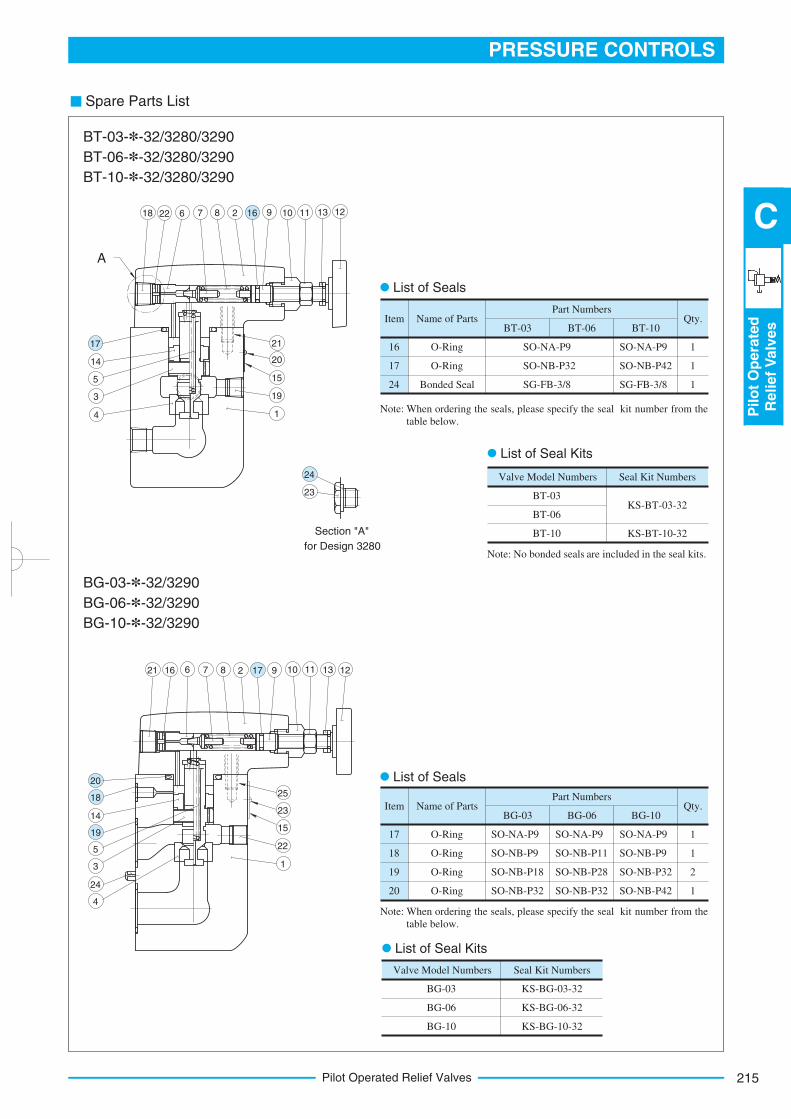
Pilot Operated Relief Valves
Spare Parts List
Name of PartsPart Numbers
Qty.
1
1
1
O-Ring
O-Ring
Bonded Seal
16
17
24
SO-NA-P9
SO-NB-P32
SG-FB-3/8
ItemBT-03 BT-06 BT-10
SO-NA-P9
SO-NB-P42
SG-FB-3/8
Name of PartsPart Numbers
Qty.
1
1
2
1
O-Ring
O-Ring
O-Ring
O-Ring
17
18
19
20
SO-NA-P9
SO-NB-P9
SO-NB-P18
SO-NB-P32
ItemBG-03 BG-06 BG-10
SO-NA-P9
SO-NB-P11
SO-NB-P28
SO-NB-P32
SO-NA-P9
SO-NB-P9
SO-NB-P32
SO-NB-P42
Valve Model Numbers Seal Kit Numbers
BG-03
BG-06
BG-10
KS-BG-03-32
KS-BG-06-32
KS-BG-10-32
Valve Model Numbers Seal Kit Numbers
BT-03
BT-06
BT-10
KS-BT-03-32
KS-BT-10-32
21
20
15
19
14
3
5
14
18 22 6 7 8 9 10 11 13 12
21 16 6 7 8 2 9 10 11 13 12
25
23
15
22
1
14
5
3
24
4
A
23
List of Seal Kits
List of Seals
List of Seals
List of Seal Kits
Note: When ordering the seals, please specify the seal kit number from the
table below.
Note: No bonded seals are included in the seal kits.
Note:
BT-03-*-32/3280/3290
BT-06-*-32/3280/3290
BT-10-*-32/3280/3290
Section "A"
for Design 3280
BG-03-*-32/3290
BG-06-*-32/3290
BG-10-*-32/3290
When ordering the seals, please specify the seal kit number from the
table below.
2 16
17
24
17
20
18
19
Low Noise Type Pilot Operated Relief Valves216
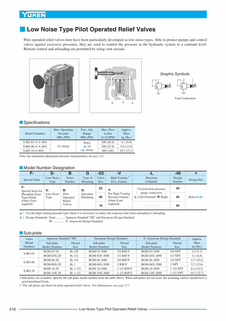
Low Noise Type Pilot Operated Relief Valves
Pilot operated relief valves here have been particularly developed as low-noise types. Able to protect pumps and control
valves against excessive pressures, they are used to control the pressure in the hydraulic system to a constant level.
Remote control and unloading are permitted by using vent circuits.
Specifications
Graphic Symbols
Vent Connection
1.
2.
1
2
Model Numbers
Max. Operating
Pressure
MPa (PSI)
Pres. Adj.
Range
MPa (PSI)
Approx.
Mass
kg (lbs.)
Max. Flow
L/min
(U.S.GPM)
S-BG-03-*-*-40* 100 (26.4)
200 (52.8)
400 (106)
4.1 (9.0)
5.0 (11.0)
10.5 (23.2)
S-BG-06-*-*-40*S-BG-10-*-40*
25 (3630)
Note)
-25
( -3630)
*Design Std.
-40Design
Number
40
40
40
L: Left (Normal) R: Right
High Venting
Pres. Feature
-V -LDirection
of Handle
Viewed from pressure
gauge connection
-03GBS-F-Valve
Size
Type of
Mounting
Series
Number
Low Noise
TypeSpecial Seals
03
06
10
F:
Special Seals for Phosphate Ester Type Fluids (Omit if not required)
S:
Low Noise Type
B:
PilotOperatedReliefValves
G:
Sub-plate Mounting
V:For High VentingPressure Feature(Omit if notrequired)
Valve
Model
Numbers
Sub-plate
Model Numbers
Thread
Size
Sub-plate
Model Numbers
Thread
Size
Sub-plate
Model Numbers
Thread
Size
Approx.
Mass
kg (lbs.)
Japanese Standard "JIS" European Design Standard N. American Design Standard
S-BG-03
S-BG-06
S-BG-10
BGM-03-20
BGM-03X-20
BGM-06-20
BGM-06X-20
BGM-10-20
BGM-10X-20
Rc 3/8
Rc 1/2
Rc 3/4
Rc 1
Rc 1-1/4
Rc 1-1/2
BGM-03-3080
BGM-03X-3080
BGM-06-3080
BGM-06X-3080
BGM-10-3080
BGM-10X-3080
BGM-03-2090
BGM-03X-2090
BGM-06-2090
BGM-06X-2090
BGM-10-2090
BGM-10X-2090
3/8 BSP.F
1/2 BSP.F
3/4 BSP.F
1 BSP.F
1-1/4 BSP.F
1-1/2 BSP.F
3/8 NPT
1/2 NPT
3/4 NPT
1 NPT
1-1/4 NPT
1-1/2 NPT
2.4 (5.3)
3.1 (6.8)
4.7 (10.4)
5.7 (12.6)
8.4 (18.5)
10.3 (22.7)
Design Standards: None
90
Japanese Standard "JIS" and European Design Standard
N. American Design Standard
...........
...............
Refer to
Note: See minimum adjustment pressure characteristics on page 218.
Use the high venting pressure type where it is necessary to reduce the response time from unloading to onloading.
The sub-plates are those for pilot operated relief valves. For dimensions, see page 213.
Sub-plate
Model Number Designation
Sub-plates are available. Specify the sub-plate model number from the table above. When sub-plates are not used, the mounting surface should have a
good machined finish.
217
PRESSURE CONTROLS
Lo
wN
ois
eTyp
eP
ilo
tO
pera
ted
Relief
Valv
es
C
Low Noise Type Pilot Operated Relief Valves
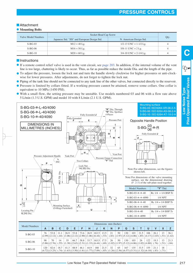
DIMENSIONS INMILLIMETRES (INCHES)
Mounting surface
S-BG-03: ISO 6264-AR-06-2-A
S-BG-06: ISO 6264-AS-08-2-A
S-BG-10: ISO 6264-AT-10-2-A
Valve Model NumbersJapanese Std. "JIS" and European Design Std. N. American Design Std.
Socket Head Cap Screw
S-BG-03
S-BG-06
S-BG-10
Qty.
M12 40 Lg.
M16 50 Lg.
M20 60 Lg.
1/2-13 UNC 1-1/2 Lg.
5/8-11 UNC 2 Lg.
3/4-10 UNC 2-1/4 Lg.
4
4
4
Model Numbers
S-BG-03
S-BG-06
S-BG-10
76 (2.99)
163.5 (6.44)
A D
Dimensions mm (Inches)
B C E F H J K N P Q S T U V X Z
98 (3.86)
120 (4.72)
53.8 (2.12)
82.6 (3.25)
70 (2.76)
11.1 (.44)
18.7 (.74)
14 (.55)
26.9 (1.06)
41.3 (1.63)
35 (1.38)
53.8 (2.12)
88.9 (3.50)
66.7 (2.63)
73.6 (2.90)
46.1(1.81)
58.8 (2.31)
26.9 (1.06)
44.9 (1.77)
33.7 (1.33)
180 (7.09)
163.5 (6.44)
13.5 (.53)
21.5 (.85)
17.5 (.69)
21 (.83)
32 (1.26)
26 (1.02)
50 (1.97)
65 (2.56)
50 (1.97)
130 (5.12)
167 (6.57)
130 (5.12)
103 (4.06)
135 (5.31)
103 (4.06)
21.5 (.85)
33.5 (1.32)
26 (1.02)
106 (4.17)
155 (6.10)
122 (4.80)
26.1 (1.03)
21.1(.83)
19.3 (.76)
13 (.51)
18 (.71)
13 (.51)
36.1 (1.42)
21.3 (.84)
Z
Fully Extended J
Mounting Surface (O-Rings Furnished)
Locating Pin
6(.24) Dia.
44(1
.73)
Dia
.
INC.
Pressure Adjustment Handle
Two Collars
Lock Nut 14(.55) Dia.
U
V
X
T
Pressure Gauge Connection
"Y" Thd
Vent PortH
Tank Port
FFully Extended
Fully Extended J
E Pressure Port
C
D
B A
S
Q
P
"K" Dia. Through
"N" Dia. Spotface 4 Places
6
(.24)
Attachment
Mounting Bolts
Instructions
S-BG-03-*-L-40/4090
Model Numbers "Y" Thd.
S-BG-03-*-*-40
S-BG-03-*-*-4090
S-BG-06-*-*-40
S-BG-06-*-*-4090
S-BG-10-*-40
S-BG-10-*-4090
Rc 1/4 = 1/4 BSP.Tr
1/4 NPT
Rc 1/4 = 1/4 BSP.Tr
1/4 NPT
Rc 1/4 = 1/4 BSP.Tr
1/4 NPT
Note:For dimensions of the valve mounting surface, see the dimensional drawing (P. 213) of the sub-plate used together.
Note:For other dimensions, see the figures shown left.
S-BG- -*-R03 06
Opposite Handle Position
S-BG-06-*-L-40/4090
S-BG-10-*-40/4090
If a remote control relief valve is used in the vent circuit, see page 203. In addition, if the internal volume of the vent
line is too large, chattering is likely to occur. Thus, as far as possible reduce the inside Dia. and the length of the pipe.
To adjust the pressure, loosen the lock nut and turn the handle slowly clockwise for higher pressures or anti-clock-
wise for lower pressures. After adjustments, do not forget to tighten the lock nut.
Piping of the tank line should not be connected to any tank line of the other valves, but connected directly to the reservoir.
Pressure is limited by collars fitted. If a working pressure cannot be attained, remove some collars. One collar is
equivalent to 10 MPa (1450 PSI).
With a small flow, the setting pressure may be unstable. Use models numbered 03 and 06 with a flow rate above
5 L/min (1.3 U.S. GPM) and model 10 with 8 L/min (2.1 U.S. GPM).
Low Noise Type Pilot Operated Relief Valves218
3700
33003500
2200
1900
250
PSI
252423
151413
1.51.0
MPa
Pre
ssure
0.550
PSI
252423
151413
1.51.0
MPa
Pre
ssure
0.5
36003400
2200
1900
PSI252423
151413
2.01.5
MPa
Pre
ssure
1.0
3200
300
150
22
0 20 40 60 80L/min
0 5 10 15 20 25U.S. GPM
Flow Rate
100 0 50 100 150 200L/min
0 10 20 30 40 50U.S. GPM
Flow Rate
0 100 200 300 400L/min
0 25 50 75 100U.S. GPM
Flow Rate
0 20 40 60 80 L/min
0 5 10 15 20 25U.S. GPM
Flow Rate
100
PSI
0.1
MPa
Pre
ssure
00
0.2
0.3
0.4
0.5
0.6
0.7
0.8
0.9
20
40
60
80
100
120
PSI MPa
Pre
ssure
00
0.2
0.4
0.8
1.0
1.2
1.4
50
100
150
200
0.6
PSI MPa
Pre
ssure
0.2
0
0.4
0.6
1.0
1.2
1.4
1.6
50
100
150
200
0.8
0
225
0 50 100L/min
0 10 20 30 40 50U.S. GPM
Flow Rate
200150 0 100 200L/min
0 25 50 75 100U.S. GPM
Flow Rate
400300
0 4 8 12 16 MPa
0 1000 2000
Pressure
20
3000 PSI
0 4 8 12 16 MPa
0 1000 2000
Pressure
20
3000 PSI
0 4 8 12 16 MPa
0 1000 2000Pressure
20
3000 PSI
dB(A)
Nois
e L
evel
40
50
60
80
70
dB(A)
Nois
e L
evel
40
50
60
80
70
dB(A)
Nois
e L
evel
40
50
60
80
70
High Vent
Low Vent Pressure Type
High Vent
Pressure Type
Low Vent Pressure Type
High Vent
Pressure Type
Low Vent Pressure Type
Vent PressureMin. Adjustment Pressure
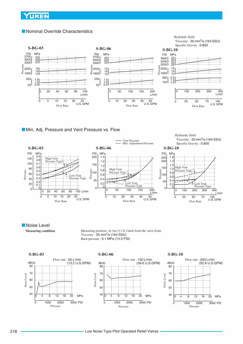
Min. Adj. Pressure and Vent Pressure vs. Flow
Hydraulic fluid:
Viscosity : 2 35 mm /s (164 SSU)
Specific Gravity : 0.850
Nominal Override Characteristics
Noise Level
Hydraulic fluid:
Viscosity : 2 35 mm /s (164 SSU)
Specific Gravity : 0.850
Viscosity : 2 35 mm /s (164 SSU)
Back pressure : 0.1 MPa (14.5 PSI)
Measuring position: At 1m (3.3 ft.) back from the valve front.Measuring condition
Flow rate : 50 L/min(13.2 U.S.GPM)
Flow rate : 150 L/min(39.6 U.S.GPM)
Flow rate : 200 L/min(52.8 U.S.GPM)
S-BG-03 S-BG-06 S-BG-10
S-BG-03 S-BG-06 S-BG-10
S-BG-03 S-BG-06 S-BG-10
3700
33003500
2200
1900
250
50
Pressure Type
219
PRESSURE CONTROLS
Lo
wN
ois
eTyp
eP
ilo
tO
pera
ted
Relief
Valv
es
C
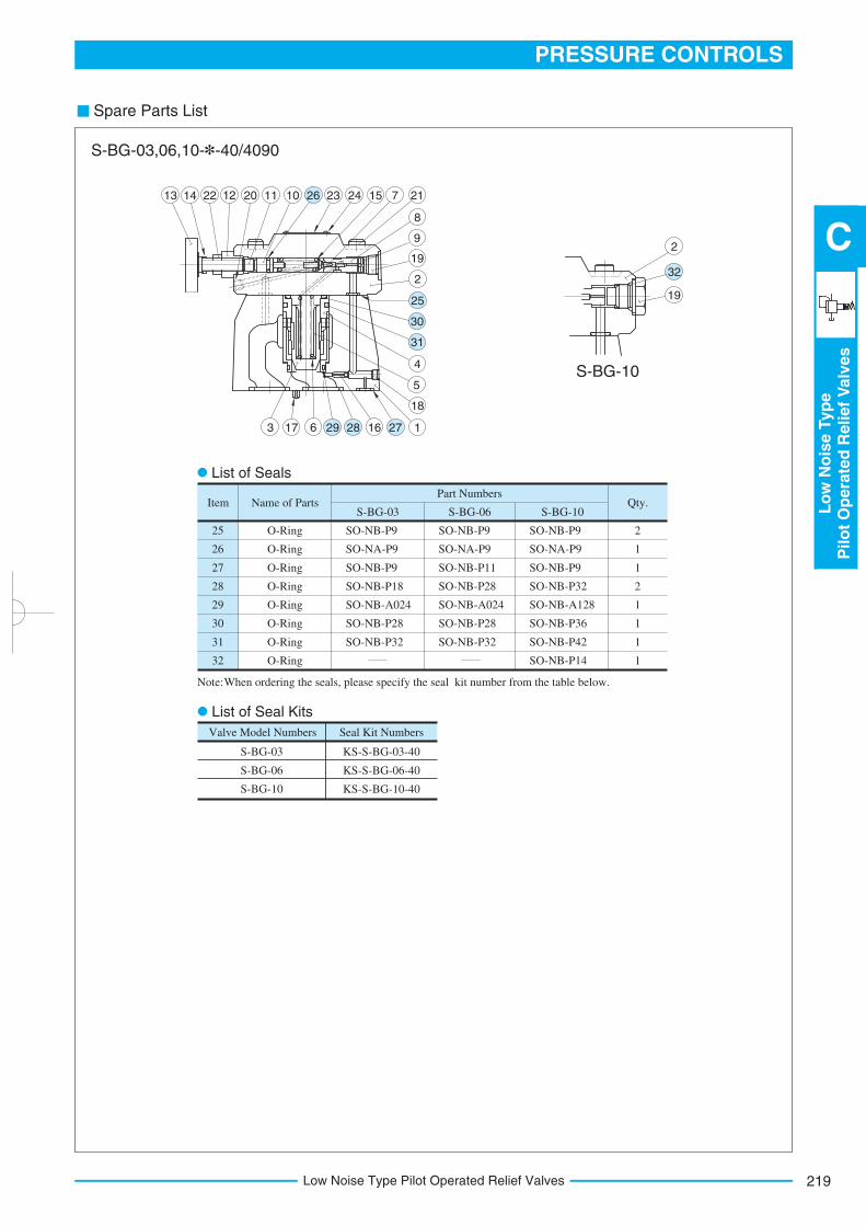
Low Noise Type Pilot Operated Relief Valves
Spare Parts List
Name of PartsPart Numbers
Qty.
O-Ring
O-Ring
O-Ring
O-Ring
O-Ring
O-Ring
O-Ring
O-Ring
SO-NB-P9
SO-NA-P9
SO-NB-P9
SO-NB-P18
SO-NB-A024
SO-NB-P28
SO-NB-P32
ItemS-BG-03 S-BG-06 S-BG-10
25
26
27
28
29
30
31
32
2
1
1
2
1
1
1
1
SO-NB-P9
SO-NA-P9
SO-NB-P11
SO-NB-P28
SO-NB-A024
SO-NB-P28
SO-NB-P32
SO-NB-P9
SO-NA-P9
SO-NB-P9
SO-NB-P32
SO-NB-A128
SO-NB-P36
SO-NB-P42
SO-NB-P14
Valve Model Numbers Seal Kit Numbers
S-BG-03
S-BG-06
S-BG-10
KS-S-BG-03-40
KS-S-BG-06-40
KS-S-BG-10-40
10 23 24 15 7 21
8
9
19
2
4
5
18
1166173
2
19
112012221413
S-BG-03,06,10-*-40/4090
S-BG-10
List of Seals
List of Seal Kits
Note:When ordering the seals, please specify the seal kit number from the table below.
26
25
30
31
272829
32
Solenoid Controlled Relief Valves220
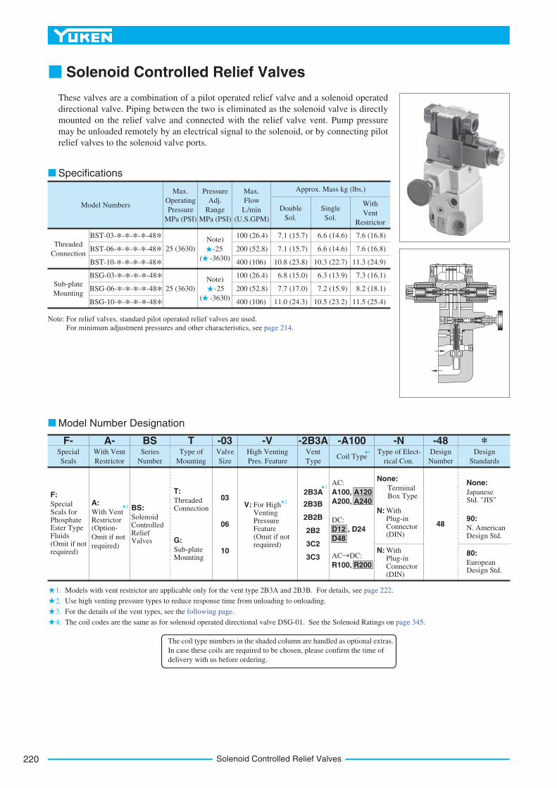
Solenoid Controlled Relief Valves
These valves are a combination of a pilot operated relief valve and a solenoid operated
directional valve. Piping between the two is eliminated as the solenoid valve is directly
mounted on the relief valve and connected with the relief valve vent. Pump pressure
may be unloaded remotely by an electrical signal to the solenoid, or by connecting pilot
relief valves to the solenoid valve ports.
1.
2.
3.
12
3
Model Numbers
Max.
Operating
Pressure
MPa (PSI)
Pressure
Adj.
Range
MPa (PSI)
Single
Sol.
Double
Sol.
Max.
Flow
L/min
(U.S.GPM)
Approx. Mass kg (lbs.)
With
Vent
Restrictor
25 (3630)
Note)
-25
( -3630)
Note)
-25
( -3630)
25 (3630)
100
200
400
(26.4)
(52.8)
(106)
100
200
400
(26.4)
(52.8)
(106)
7.1
7.1
10.8
(15.7)
(15.7)
(23.8)
6.8
7.7
11.0
(15.0)
(17.0)
(24.3)
6.6
6.6
10.3
(14.6)
(14.6)
(22.7)
6.3
7.2
10.5
(13.9)
(15.9)
(23.2)
7.6
7.6
11.3
(16.8)
(16.8)
(24.9)
7.3
8.2
11.5
(16.1)
(18.1)
(25.4)
Threaded
Connection
Sub-plate
Mounting
BST-03-*-*-*-*-48*BST-06-*-*-*-*-48*BST-10-*-*-*-*-48*BSG-03-*-*-*-*-48*BSG-06-*-*-*-*-48*BSG-10-*-*-*-*-48*
F-Special
Seals
F:
Special Seals for Phosphate Ester Type Fluids (Omit if not required)
A:
With Vent Restrictor (Option-
Omit if not
required)
BS:
Solenoid Controlled Relief Valves
T:
Threaded Connection
G:
Sub-plate Mounting
03
06
10
V: For High Venting Pressure Feature (Omit if not required)
2B3A
2B3B
2B2B
2B2
3C2
3C3
None:
Terminal Box Type
N: With Plug-in Connector (DIN)
N: With Plug-in Connector (DIN)
48
AC:
A100, A120
A200, A240
DC:
D12 , D24
D48
AC DC:
R100, R200
None:
Japanese Std. "JIS"
90:
N. American Design Std.
80:
European Design Std.
Series
Number
A-Type of
Mounting
Valve
Size
High Venting
Pres. Feature
Design
Standards
*Design
Number
With Vent
Restrictor
Vent
TypeCoil Type
Type of Elect-
rical Con.
BS T -03 -V -2B3A -A100 -N -48
Specifications
Model Number Designation
Note: For relief valves, standard pilot operated relief valves are used.
For minimum adjustment pressures and other characteristics, see page 214.
Models with vent restrictor are applicable only for the vent type 2B3A and 2B3B. For details, see page 222.
Use high venting pressure types to reduce response time from unloading to onloading.
For the details of the vent types, see the following page.
4. The coil codes are the same as for solenoid operated directional valve DSG-01. See the Solenoid Ratings on page 345.
The coil type numbers in the shaded column are handled as optional extras.
In case these coils are required to be chosen, please confirm the time of
delivery with us before ordering.
4
221
PRESSURE CONTROLS
So
len
oid
Co
ntr
olled
Relief
Valv
es
C
Solenoid Controlled Relief Valves
Valve Model
Numbers Japanese Std. "JIS" and European Design Std. N. American Design Std.
Socket Head Cap Screw
BSG-03
BSG-06
BSG-10
M12 70 Lg. (2 pcs.), M12 95 Lg. (2 pcs.)
M16 60 Lg. (2 pcs.), M16 80 Lg. (2 pcs.)
M20 70 Lg. (2 pcs.), M20 90 Lg. (2 pcs.)
1/2-13UNC 2-3/4 Lg. (2 pcs.), 1/2-13UNC 3-3/4 Lg. (2 pcs.)
5/8-11UNC 2-1/4 Lg. (2 pcs.), 5/8-11UNC 3-1/4 Lg. (2 pcs.)
3/4-10UNC 2-3/4 Lg. (2 pcs.), 3/4-10UNC 3-1/2 Lg. (2 pcs.)
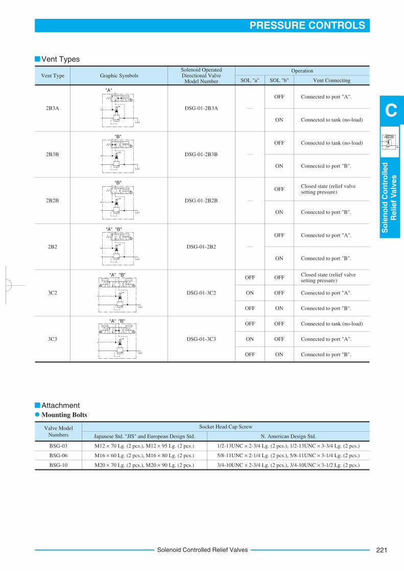
Vent Type
2B3A
2B3B
2B2B
2B2
3C2
3C3
Graphic SymbolsSolenoid Operated Directional Valve Model Number SOL "a"
OFF
OFF
ON
OFF
OFF
ON
Vent Connecting
Operation
OFF
ON
OFF
ON
OFF
ON
OFF
ON
OFF
ON
OFF
OFF
ON
OFF
SOL "b"
DSG-01-2B3A
DSG-01-2B3B
DSG-01-2B2B
DSG-01-2B2
DSG-01-3C2
DSG-01-3C3
Connected to port "A".
Connected to tank (no-load)
Connected to tank (no-load)
Connected to port "B".
Closed state (relief valve setting pressure)
Connected to port "B".
Connected to port "B".
Connected to port "A".
Connected to port "A".
Connected to port "B".
Closed state (relief valve setting pressure)
Connected to tank (no-load)
Connected to port "A".
Connected to port "B".
Attachment
Mounting Bolts
Vent Types
"A"
b
b
b
b
"B"
ba
ba
"B"
"A" "B"
"A" "B"
"A" "B"
Solenoid Controlled Relief Valves222
Valve
Model
Numbers
Japanese Standard "JIS" European Design Standard N. American Design StandardApprox.
Mass
kg (lbs.)Sub-plate
Model Numbers
Thread
Size
Sub-plate
Model Numbers
Thread
Size
Sub-plate
Model Numbers
Thread
Size
BSG-03
BSG-06
BSG-10
BGM-03-20
BGM-03X-20
BGM-06-20
BGM-06X-20
BGM-10-20
BGM-10X-20
Rc 3/8
Rc 1/2
Rc 3/4
Rc 1
Rc 1-1/4
Rc 1-1/2
BGM-03-3080
BGM-03X-3080
BGM-06-3080
BGM-06X-3080
BGM-10-3080
BGM-10X-3080
3/8 BSP.F
1/2 BSP.F
3/4 BSP.F
1 BSP.F
1-1/4 BSP.F
1-1/2 BSP.F
BGM-03-2090
BGM-03X-2090
BGM-06-2090
BGM-06X-2090
BGM-10-2090
BGM-10X-2090
3/8 NPT
1/2 NPT
3/4 NPT
1 NPT
1-1/4 NPT
1-1/2 NPT
2.4
3.1
4.7
5.7
8.4
10.3
(5.3)
(6.8)
(10.4)
(12.6)
(18.5)
(22.7)
Interchangeability in Installation between Old and New Design.
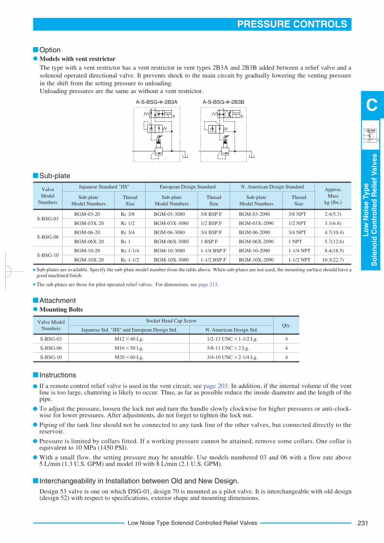
Sub-plate
The sub-plates are those for pilot operated relief valves. For dimensions, see page 213.
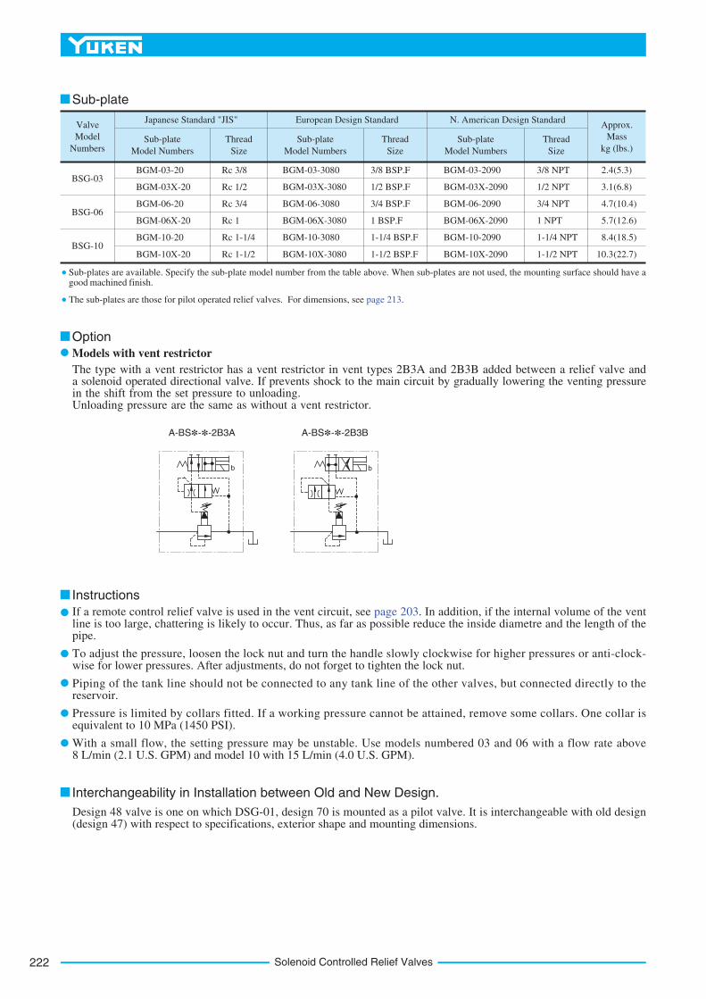
Option
Models with vent restrictor
A-BS*-*-2B3A A-BS*-*-2B3B
Sub-plates are available. Specify the sub-plate model number from the table above. When sub-plates are not used, the mounting surface should have a good machined finish.
The type with a vent restrictor has a vent restrictor in vent types 2B3A and 2B3B added between a relief valve and a solenoid operated directional valve. If prevents shock to the main circuit by gradually lowering the venting pressure in the shift from the set pressure to unloading.Unloading pressure are the same as without a vent restrictor.
Instructions
If a remote control relief valve is used in the vent circuit, see page 203. In addition, if the internal volume of the vent line is too large, chattering is likely to occur. Thus, as far as possible reduce the inside diametre and the length of the pipe.
To adjust the pressure, loosen the lock nut and turn the handle slowly clockwise for higher pressures or anti-clock-wise for lower pressures. After adjustments, do not forget to tighten the lock nut.
Piping of the tank line should not be connected to any tank line of the other valves, but connected directly to the reservoir.
Pressure is limited by collars fitted. If a working pressure cannot be attained, remove some collars. One collar is equivalent to 10 MPa (1450 PSI).
With a small flow, the setting pressure may be unstable. Use models numbered 03 and 06 with a flow rate above 8 L/min (2.1 U.S. GPM) and model 10 with 15 L/min (4.0 U.S. GPM).
Design 48 valve is one on which DSG-01, design 70 is mounted as a pilot valve. It is interchangeable with old design (design 47) with respect to specifications, exterior shape and mounting dimensions.
b b
223
PRESSURE CONTROLS
So
len
oid
Co
ntr
olled
Relief
Valv
es
C
Solenoid Controlled Relief Valves
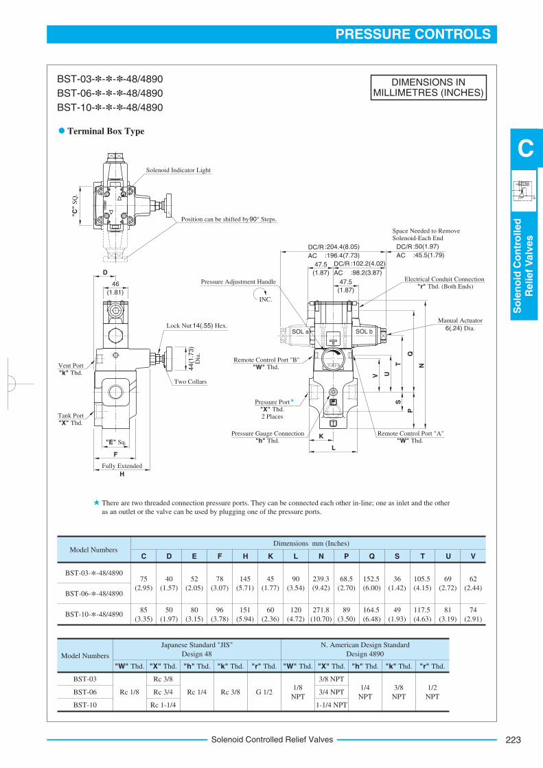
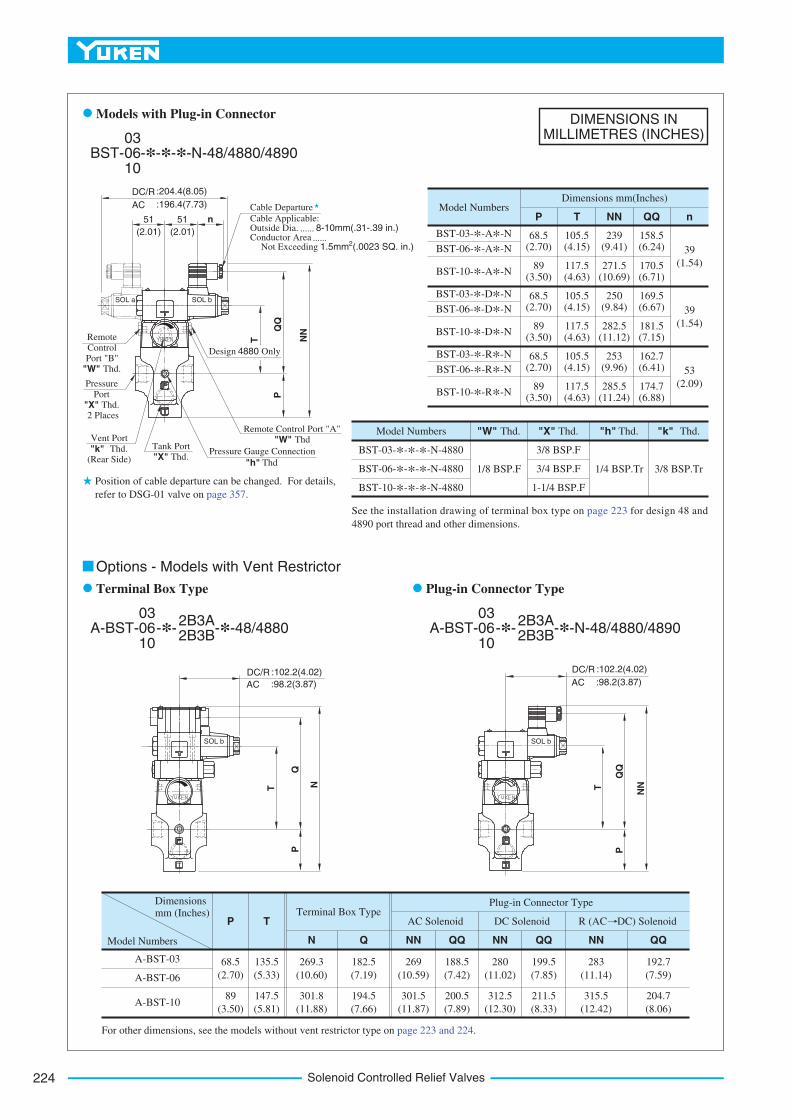
DIMENSIONS INMILLIMETRES (INCHES)
Model NumbersDimensions mm (Inches)
BST-03-*-48/4890
BST-06-*-48/4890
BST-10-*-48/4890
75
(2.95)
C D E
40
(1.57)
52
(2.05)
78
(3.07)
45
(1.77)
85
(3.35)
50
(1.97)
80
(3.15)
96
(3.78)
60
(2.36)
F H K L N P Q S T U V
145
(5.71)
151
(5.94)
90
(3.54)
120
(4.72)
239.3
(9.42)
271.8
(10.70)
68.5
(2.70)
89
(3.50)
152.5
(6.00)
164.5
(6.48)
36
(1.42)
49
(1.93)
105.5
(4.15)
117.5
(4.63)
69
(2.72)
81
(3.19)
62
(2.44)
74
(2.91)
Model Numbers
BST-03
BST-06
BST-10
"X" Thd. "h" Thd. "k" Thd. "r" Thd. "W" Thd. "X" Thd. "h" Thd. "k" Thd. "r" Thd.
Rc 3/8
Rc 3/4
Rc 1-1/4
3/8 NPT
3/4 NPT
1-1/4 NPT
Rc 1/8 Rc 1/4 Rc 3/8 G 1/21/8
NPT
1/4
NPT
3/8
NPT
1/2
NPT
Japanese Standard "JIS"
Design 48
N. American Design Standard
Design 4890
"W" Thd.
BST-03-*-*-*-48/4890
BST-06-*-*-*-48/4890
BST-10-*-*-*-48/4890
Terminal Box Type
There are two threaded connection pressure ports. They can be connected each other in-line; one as inlet and the other
as an outlet or the valve can be used by plugging one of the pressure ports.
SOL a SOL b
Solenoid Indicator Light
Position can be shifted by 90° Steps.
"C"
SQ
.
Lock Nut 14(.55) Hex.
Vent Port
"k" Thd.
Tank Port
"X" Thd.
Two Collars
44(1
.73)
Dia
.
F
H
Fully Extended
46
(1.81)
D
"E" Sq.
DC/R
AC
AC
Space Needed to Remove Solenoid-Each End
DC/R :50(1.97)
:45.5(1.79)
:102.2(4.02)
:98.2(3.87)
47.5
(1.87)
47.5
(1.87)
DC/R
AC
:204.4(8.05)
:196.4(7.73)
INC.
Pressure Adjustment Handle Electrical Conduit Connection
"r" Thd. (Both Ends)
Remote Control Port "B"
"W" Thd.
Manual Actuator
6(.24) Dia.
Remote Control Port "A"
"W" Thd.K
L
Pressure Port
"X" Thd. 2 Places
V U
TS
Q
N
P
Pressure Gauge Connection
"h" Thd.
Solenoid Controlled Relief Valves224
DIMENSIONS INMILLIMETRES (INCHES)
Model Numbers
P
68.5
(2.70)
Dimensionsmm (Inches)
T
N Q NN QQ NN QQ NN QQ
135.5
(5.33)
269.3
(10.60)
182.5
(7.19)
269
(10.59)
188.5
(7.42)
280
(11.02)
199.5
(7.85)
283
(11.14)
192.7
(7.59)
147.5
(5.81)
301.8
(11.88)
194.5
(7.66)
301.5
(11.87)
200.5
(7.89)
312.5
(12.30)
211.5
(8.33)
315.5
(12.42)
204.7
(8.06)
89
(3.50)
Terminal Box TypeAC Solenoid DC Solenoid
Plug-in Connector Type
A-BST-03
A-BST-06
A-BST-10
Model Numbers
BST-03-*-*-*-N-4880
BST-06-*-*-*-N-4880
BST-10-*-*-*-N-4880
1/8 BSP.F 1/4 BSP.Tr 3/8 BSP.Tr
3/8 BSP.F
3/4 BSP.F
1-1/4 BSP.F
"X" Thd."W" Thd. "h" Thd. "k" Thd.
53
(2.09)174.7(6.88)
285.5(11.24)
117.5(4.63)
89 (3.50)
BST-03-*-R*-N
BST-06-*-R*-N
BST-10-*-D*-N
BST-10-*-R*-N
BST-10-*-A*-N
BST-03-*-D*-N
BST-06-*-D*-N
BST-03-*-A*-N
BST-06-*-A*-N
39
(1.54)
39
(1.54)
68.5 (2.70)
105.5(4.15)
253(9.96)
162.7(6.41)
89 (3.50)
117.5(4.63)
282.5(11.12)
181.5(7.15)
68.5 (2.70)
105.5(4.15)
250(9.84)
169.5(6.67)
89 (3.50)
117.5(4.63)
271.5(10.69)
170.5(6.71)
68.5 (2.70)
105.5(4.15)
239(9.41)
158.5(6.24)
P T NN QQ n
Dimensions mm(Inches)Model Numbers
For other dimensions, see the models without vent restrictor type on page 223 and 224.
Options - Models with Vent Restrictor
BST- -*-*-*-N-48/4880/489003 06 10
Models with Plug-in Connector
A-BST-03 06 10
-*-2B3A 2B3B
-*-48/488003 06 10
-*-2B3A 2B3B
-*-N-48/4880/4890
Terminal Box Type Plug-in Connector Type
A-BST-
See the installation drawing of terminal box type on page 223 for design 48 and
4890 port thread and other dimensions.
R (AC DC) Solenoid
SOL b
SOL bSOL a
SOL b
Cable Applicable: Outside Dia. ...... 8-10mm(.31-.39 in.)Conductor Area ......
Not Exceeding 2 1.5mm (.0023 SQ. in.)
DC/R
AC
:204.4(8.05)
:196.4(7.73)
(2.01)
51
(2.01)
51 n
T
NN
P
Design 4880 Only
Remote Control Port "A"
"W" Thd
Pressure Gauge Connection
"h" Thd
Tank Port
"X" Thd.
Vent Port
"k" Thd. (Rear Side)
Pressure
Port
"X" Thd. 2 Places
Remote
Control Port "B"
"W" Thd.
Position of cable departure can be changed. For details,
refer to DSG-01 valve on page 357.
Cable Departure
T
P
DC/R :102.2(4.02)
AC :98.2(3.87)
Q
N
DC/R :102.2(4.02)
AC :98.2(3.87)
T
NN
P
225
PRESSURE CONTROLS
So
len
oid
Co
ntr
olled
Relief
Valv
es
C
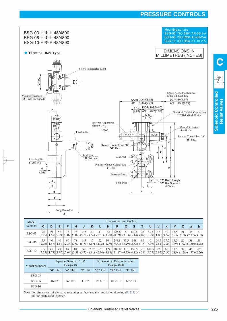
Solenoid Controlled Relief Valves
DIMENSIONS INMILLIMETRES (INCHES)
Mounting surface
BSG-03: ISO 6264-AR-06-2-A
BSG-06: ISO 6264-AS-08-2-A
BSG-10: ISO 6264-AT-10-2-A
Model
Numbers
BSG-03
BSG-06
BSG-10
75 (2.95)
225.8(8.89)
85 (3.35)
C D E F H J K L N P Q S T U V X Y Z a b
Dimensions mm (Inches)
283.8(11.17)
249.8(9.83)
75 (2.95)
40 (1.57)
45 (1.77)
40 (1.57)
57 (2.24)
47 (1.85)
40 (1.57)
78 (3.07)
67 (2.64)
60 (2.36)
78 (3.07)
78 (3.07)
84 (3.31)
145 (5.71)
145 (5.71)
146 (5.75)
14.1 (.56)
17 (.67)
20.7 (.81)
41 (1.61)
52 (2.05)
62 (2.44)
82 (3.23)
104 (4.09)
124 (4.88)
77 (3.03)
83.5 (3.29)
110 (4.33)
130.5(5.14)
148(5.83)
155.5(6.12)
22 (.87)
4.5 (.18)
6 (.24)
83.5(3.29)
101(3.98)
108.5(4.27)
47 (1.85)
64.5 (2.54)
72 (2.83)
40 (1.57)
57.5 (2.26)
65 (2.56)
13.5 (.53)
17.5 (.69)
21.5 (.85)
21 (.83)
26 (1.02)
32 (1.26)
77 (3.03)
58 (2.28)
65 (2.56)
55 (2.17)
38 (1.50)
45 (1.77)
Model Numbers
BSG-03
BSG-06
BSG-10
Rc 1/8 Rc 1/4 G 1/2 1/8 NPT 1/4 NPT 1/2 NPT
Japanese Standard "JIS"
Design 48
N. American Design Standard
Design 4890
"d" Thd. "e" Thd. "f" Thd. "d" Thd. "e" Thd. "f" Thd.
BSG-03-*-*-*-48/4890BSG-06-*-*-*-48/4890BSG-10-*-*-*-48/4890
Terminal Box Type
Note: For dimensions of the valve mounting surface, see the installation drawing (P. 213) of the sub-plate used together.
SOL b
Solenoid Indicator Light
"C"
SQ
.
Mounting Surface (O-Rings Furnished)
D
46
(1.81)
Lock Nut 14(.55) Hex.
Two Collars
Locating Pin
6(.24) Dia.
6
(.24)
a
E
b
F
H
J
Fully Extended
44(1
.73)
Dia
.Space Needed to Remove Solenoid-Each End
DC/R
AC
:102.2(4.02)
:98.2(3.87)
47.5
(1.87)
DC/R
AC
:204.4(8.05)
:196.4(7.73)
(1.87)
47.5
DC/R
AC
:50(1.97)
:45.5(1.79)
Manual Actuator
Remote Control Port "A"
"d" Thd.
"Y" Dia. Through
"Z" Dia. Spotface 4 Places
S
P
K
L
N
Remote Control Port "B"
"d" Thd.
Pressure Port
Tank Port
Pressure Gauge Connection
"e" Thd.
INC.
Pressure Adjustment Handle
Electrical Conduit Connection
"f" Thd. (Both Ends)
6(.24) Dia.
X V
U
Q
T
Vent Port
SOL a
Solenoid Controlled Relief Valves226
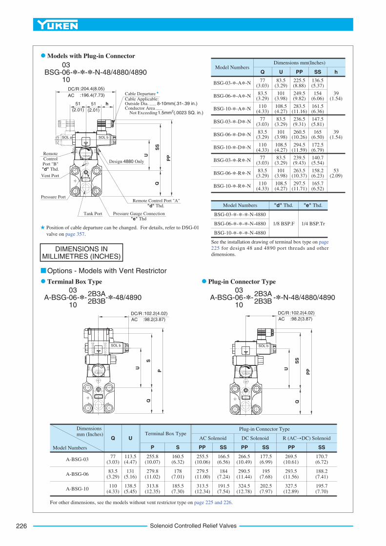
DIMENSIONS INMILLIMETRES (INCHES)
Model Numbers
Q
77 (3.03)
Dimensionsmm (Inches)
U
P S PP SS PP
83.5 (3.29)
Terminal Box TypeAC Solenoid DC Solenoid R (AC DC) Solenoid
Plug-in Connector Type
A-BSG-03
A-BSG-06
A-BSG-10110
(4.33)
PP SSSS
113.5(4.47)
131(5.16)
138.5(5.45)
255.8(10.07)
279.8(11.02)
313.8(12.35)
185.5(7.30)
178(7.01)
160.5(6.32)
255.5(10.06)
279.5(11.00)
313.5(12.34)
166.5(6.56)
184(7.24)
191.5(7.54)
266.5(10.49)
177.5(6.99)
269.5(10.61)
170.7(6.72)
290.5(11.44)
195(7.68)
293.5(11.56)
188.2(7.41)
324.5(12.78)
202.5(7.97)
327.5(12.89)
195.7(7.70)
Model Numbers
BSG-03-*-*-*-N-4880
BSG-06-*-*-*-N-4880
BSG-10-*-*-*-N-4880
1/8 BSP.F 1/4 BSP.Tr
"e" Thd."d" Thd.
77 (3.03)
83.5 (3.29)
110 (4.33)
77 (3.03)
83.5 (3.29)
110 (4.33)
77 (3.03)
83.5 (3.29)
110 (4.33)
83.5(3.29)
101(3.98)
108.5(4.27)
83.5(3.29)
101(3.98)
108.5(4.27)
83.5(3.29)
101(3.98)
108.5(4.27)
225.5(8.88)
249.5(9.82)
283.5(11.16)
236.5(9.31)
260.5(10.26)
294.5(11.59)
239.5(9.43)
263.5(10.37)
297.5(11.71)
136.5(5.37)
154(6.06)
161.5(6.36)
147.5(5.81)
165(6.50)
172.5(6.79)
140.7(5.54)
158.2(6.23)
165.7(6.52)
39 (1.54)
39 (1.54)
53 (2.09)
BSG-03-*-A*-N
BSG-06-*-A*-N
BSG-10-*-A*-N
BSG-03-*-D*-N
BSG-06-*-D*-N
BSG-10-*-D*-N
BSG-03-*-R*-N
BSG-06-*-R*-N
BSG-10-*-R*-N
Q U PP SS h
Dimensions mm(Inches)Model Numbers
For other dimensions, see the models without vent restrictor type on page 225 and 226.
BSG- -*-*-*-N-48/4880/489003 06 10
Models with Plug-in Connector
Options - Models with Vent Restrictor
A-BSG-03 06 10
-*-2B3A 2B3B
-*-48/489003 06 10
-*-2B3A 2B3B
Terminal Box Type Plug-in Connector Type
A-BSG- -*-N-48/4880/4890
See the installation drawing of terminal box type on page
225 for design 48 and 4890 port threads and other
dimensions.
SOL b SOL b
SOL bSOL a
Design 4880
Cable Departure
Cable Applicable: Outside Dia. ...... 8-10mm(.31-.39 in.)Conductor Area ......
Not Exceeding 2 1.5mm (.0023 SQ. in.)
DC/R
AC
:204.4(8.05)
:196.4(7.73)
51 51
Remote
Control Port "B"
"d" Thd.
Vent Port
Pressure Port
Tank Port Pressure Gauge Connection
"e" Thd
Remote Control Port "A"
"d" Thd.
Q
U
SS
PP
Only
(2.01) (2.01)
h
DC/R :102.2(4.02)
AC :98.2(3.87)
U
S
P
Q
DC/R :102.2(4.02)
AC :98.2(3.87)
U
SS
PP
Q
Position of cable departure can be changed. For details, refer to DSG-01
valve on page 357.
227
PRESSURE CONTROLS
So
len
oid
Co
ntr
olled
Relief
Valv
es
C
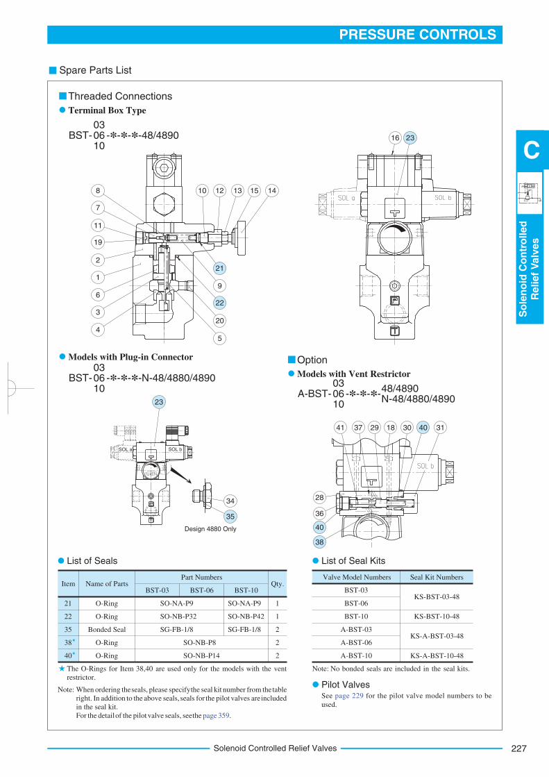
Solenoid Controlled Relief Valves
Spare Parts List
Item Name of PartsBST-03 BST-06 BST-10
Qty.Part Numbers
21
22
35
38
40
O-Ring
O-Ring
Bonded Seal
O-Ring
O-Ring
SO-NA-P9
SO-NB-P32
SG-FB-1/8
SO-NA-P9
SO-NB-P42
SG-FB-1/8
SO-NB-P8
SO-NB-P14
1
1
2
2
2
Valve Model Numbers Seal Kit Numbers
BST-03
BST-06
BST-10
A-BST-03
A-BST-06
A-BST-10
KS-BST-03-48
KS-A-BST-03-48
KS-BST-10-48
KS-A-BST-10-48
Note: When ordering the seals, please specify the seal kit number from the table
right. In addition to the above seals, seals for the pilot valves are included
in the seal kit.
For the detail of the pilot valve seals, see the page 359.
The O-Rings for Item 38,40 are used only for the models with the vent
restrictor.
List of Seal Kits
Pilot Valves
List of Seals
OptionModels with Plug-in Connector
Models with Vent Restrictor
Terminal Box Type
Threaded Connections
BST- -*-*-*-N-48/4880/489003 06 10
A-BST- -*-*-*-03 06 10
48/4890 N-48/4880/4890
BST- -*-*-*-48/489003 06 10
Note: No bonded seals are included in the seal kits.
See page 229 for the pilot valve model numbers to be
used.
SOL a SOL b
Design 4880 Only
10
9
20
5
12 13 15 148
7
11
19
1
6
3
4
221
22
23
34
35
16 23
41 37 29 18 30 40 31
28
36
40
38
Solenoid Controlled Relief Valves228
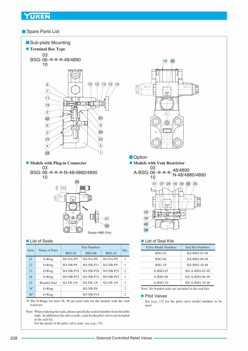
Spare Parts List
Item Name of PartsBSG-03 BSG-06 BSG-10
Qty.Part Numbers
21
22
23
24
32
38
40
O-Ring
O-Ring
O-Ring
O-Ring
Bonded Seal
O-Ring
O-Ring
SO-NA-P9
SO-NB-P9
SO-NB-P18
SO-NB-P32
SG-FB-1/8
SO-NB-P8
SO-NB-P14
1
1
2
1
2
2
2
SO-NA-P9
SO-NB-P11
SO-NB-P28
SO-NB-P32
SG-FB-1/8
SO-NA-P9
SO-NB-P9
SO-NB-P32
SO-NB-P42
SG-FB-1/8
Valve Model Numbers Seal Kit Numbers
BSG-03
BSG-06
BSG-10
A-BSG-03
A-BSG-06
A-BSG-10
KS-BSG-03-48
KS-BSG-06-48
KS-BSG-10-48
KS-A-BSG-03-48
KS-A-BSG-06-48
KS-A-BSG-10-48
Note: When ordering the seals, please specify the seal kit number from the table
right. In addition to the above seals, seals for the pilot valves are included
in the seal kit.
For the detail of the pilot valve seals, see page 359.
The O-Rings for item 38, 40 are used only for the models with the vent
restrictor.
List of Seals
Note: No bonded seals are included in the seal kits.
List of Seal Kits
Pilot Valves
Terminal Box Type
Sub-plate Mounting
BSG- -*-*-*-48/489003 06 10
Option
Models with Plug-in Connector Models with Vent Restrictor
BSG- -*-*-*-N-48/4880/489003 06 10
A-BSG- -*-*-*-03 06 10
48/4890 N-48/4880/4890
See page 229 for the pilot valve model numbers to be
used.
Design 4880 Only
31
32
2641 37 29 18 30 40 35
28
36
40
38
8
7
11
19
2
6
3
25
4
22
23
10 12 13 15 14
9
20
5
1
21
24
2616
229
PRESSURE CONTROLS
So
len
oid
Co
ntr
olled
Relief
Valv
es
C
Solenoid Controlled Relief Valves
Spare Parts List
Type of Electrical Conduit
ConnectionValve Model Numbers
Pilot Valve
Model NumbersRemarks
Japanese Standard "JIS"
N. American Design Std.
N. American Design Std.
Japanese Standard "JIS"
European Design Std.
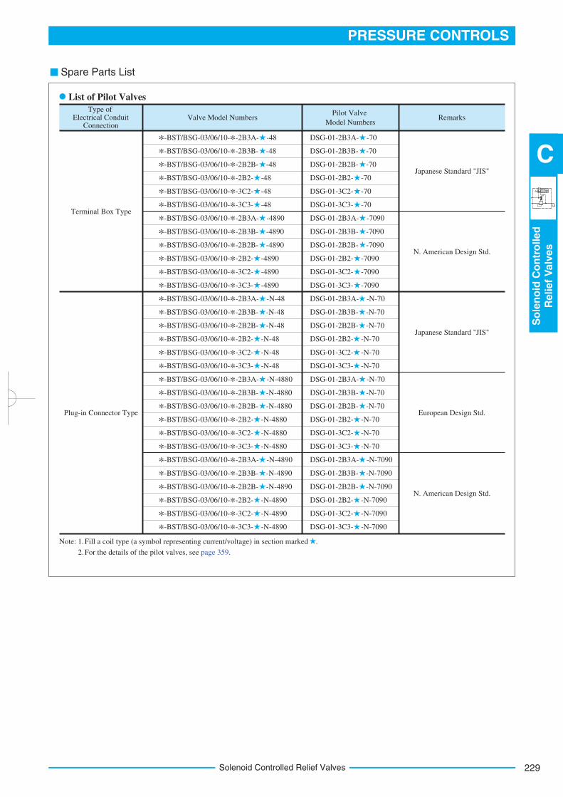
Terminal Box Type
Plug-in Connector Type
*-BST/BSG-03/06/10-*-2B3A- -48
*-BST/BSG-03/06/10-*-2B3B- -48
*-BST/BSG-03/06/10-*-2B2B- -48
*-BST/BSG-03/06/10-*-2B2- -48
*-BST/BSG-03/06/10-*-3C2- -48
*-BST/BSG-03/06/10-*-3C3- -48
*-BST/BSG-03/06/10-*-2B3A- -4890
*-BST/BSG-03/06/10-*-2B3B- -4890
*-BST/BSG-03/06/10-*-2B2B- -4890
*-BST/BSG-03/06/10-*-2B2- -4890
*-BST/BSG-03/06/10-*-3C2- -4890
*-BST/BSG-03/06/10-*-3C3- -4890
*-BST/BSG-03/06/10-*-2B3A- -N-48
*-BST/BSG-03/06/10-*-2B3B- -N-48
*-BST/BSG-03/06/10-*-2B2B- -N-48
*-BST/BSG-03/06/10-*-2B2- -N-48
*-BST/BSG-03/06/10-*-3C2- -N-48
*-BST/BSG-03/06/10-*-3C3- -N-48
*-BST/BSG-03/06/10-*-2B3A- -N-4880
*-BST/BSG-03/06/10-*-2B3B- -N-4880
*-BST/BSG-03/06/10-*-2B2B- -N-4880
*-BST/BSG-03/06/10-*-2B2- -N-4880
*-BST/BSG-03/06/10-*-3C2- -N-4880
*-BST/BSG-03/06/10-*-3C3- -N-4880
*-BST/BSG-03/06/10-*-2B3A- -N-4890
*-BST/BSG-03/06/10-*-2B3B- -N-4890
*-BST/BSG-03/06/10-*-2B2B- -N-4890
*-BST/BSG-03/06/10-*-2B2- -N-4890
*-BST/BSG-03/06/10-*-3C2- -N-4890
*-BST/BSG-03/06/10-*-3C3- -N-4890
DSG-01-2B3A- -70
DSG-01-2B3B- -70
DSG-01-2B2B- -70
DSG-01-2B2- -70
DSG-01-3C2- -70
DSG-01-3C3- -70
DSG-01-2B3A- -7090
DSG-01-2B3B- -7090
DSG-01-2B2B- -7090
DSG-01-2B2- -7090
DSG-01-3C2- -7090
DSG-01-3C3- -7090
DSG-01-2B3A- -N-70
DSG-01-2B3B- -N-70
DSG-01-2B2B- -N-70
DSG-01-2B2- -N-70
DSG-01-3C2- -N-70
DSG-01-3C3- -N-70
DSG-01-2B3A- -N-70
DSG-01-2B3B- -N-70
DSG-01-2B2B- -N-70
DSG-01-2B2- -N-70
DSG-01-3C2- -N-70
DSG-01-3C3- -N-70
DSG-01-2B3A- -N-7090
DSG-01-2B3B- -N-7090
DSG-01-2B2B- -N-7090
DSG-01-2B2- -N-7090
DSG-01-3C2- -N-7090
DSG-01-3C3- -N-7090
List of Pilot Valves
Fill a coil type (a symbol representing current/voltage) in section marked .Note: 1.
For the details of the pilot valves, see page 359.2.
Low Noise Type Solenoid Controlled Relief Valves230
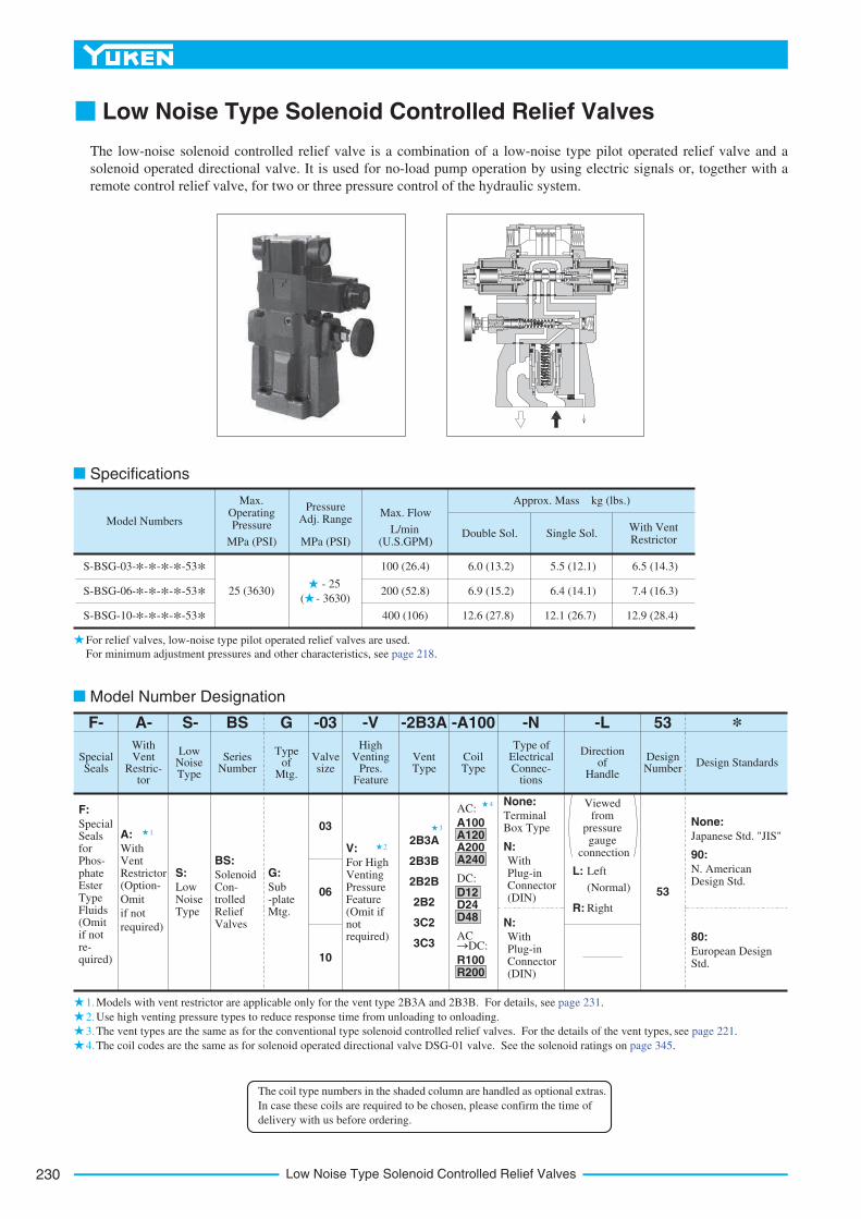
Low Noise Type Solenoid Controlled Relief Valves
The low-noise solenoid controlled relief valve is a combination of a low-noise type pilot operated relief valve and a
solenoid operated directional valve. It is used for no-load pump operation by using electric signals or, together with a
remote control relief valve, for two or three pressure control of the hydraulic system.
2
3
4
1
1.
2.
3.
4.
F-
Special Seals
F:
Special Seals for Phos- phate Ester Type Fluids (Omit if not re- quired)
A-
With Vent
Restric- tor
S-
Low Noise Type
BS
Series Number
G
Type of
Mtg.
-03
Valve size
-V
High Venting
Pres. Feature
-2B3A
Vent Type
-A100
Coil Type
-N
Type of Electrical Connec-
tions
-L
Direction of
Handle
53
Design Number
*
Design Standards
03
06
10
A:With Vent Restrictor S:
Low Noise Type
BS:
Solenoid Con- trolled Relief Valves
G:Sub -plate Mtg.
V:
For High Venting Pressure Feature (Omit if not required)
2B3A
2B3B
2B2B
2B2
3C2
3C3
AC:
A100 A120 A200 A240
DC:
D12 D24 D48
AC
R100 R200
DC:
None:
Terminal Box Type
N:
With Plug-in Connector (DIN)
N:
With Plug-in Connector (DIN)
Viewed from
pressure gauge
connection
L: Left
(Normal)
R: Right
53
None:
Japanese Std. "JIS"
90:
N. American Design Std.
80:
European Design Std.
Model Numbers
S-BSG-03-*-*-*-*-53*
S-BSG-06-*-*-*-*-53*
S-BSG-10-*-*-*-*-53*
Max. Operating Pressure
MPa (PSI)
Max. Flow
L/min(U.S.GPM)
Pressure Adj. Range
MPa (PSI)
Approx. Mass kg (lbs.)
Double Sol. Single Sol.With Vent Restrictor
25 (3630) - 25
( - 3630)
100 (26.4)
200 (52.8)
400 (106)
6.0 (13.2)
6.9 (15.2)
12.6 (27.8)
5.5 (12.1)
6.4 (14.1)
12.1 (26.7)
6.5 (14.3)
7.4 (16.3)
12.9 (28.4)
Specifications
Models with vent restrictor are applicable only for the vent type 2B3A and 2B3B. For details, see page 231.
Use high venting pressure types to reduce response time from unloading to onloading.
The vent types are the same as for the conventional type solenoid controlled relief valves. For the details of the vent types, see page 221.
The coil codes are the same as for solenoid operated directional valve DSG-01 valve. See the solenoid ratings on page 345.
Model Number Designation
For relief valves, low-noise type pilot operated relief valves are used.
For minimum adjustment pressures and other characteristics, see page 218.
(Option-
Omit
if not
required)
The coil type numbers in the shaded column are handled as optional extras.
In case these coils are required to be chosen, please confirm the time of
delivery with us before ordering.
231
PRESSURE CONTROLS
Lo
wN
ois
eTyp
eS
ole
no
idC
on
tro
lled
Relief
Valv
es
C
Low Noise Type Solenoid Controlled Relief Valves
Valve
Model
Numbers
Japanese Standard "JIS" European Design Standard N. American Design StandardApprox.
Mass
kg (lbs.)Sub-plate
Model Numbers
Thread
Size
Sub-plate
Model Numbers
Thread
Size
Sub-plate
Model Numbers
Thread
Size
S-BSG-03
S-BSG-06
S-BSG-10
BGM-03-20
BGM-03X-20
BGM-06-20
BGM-06X-20
BGM-10-20
BGM-10X-20
Rc 3/8
Rc 1/2
Rc 3/4
Rc 1
Rc 1-1/4
Rc 1-1/2
BGM-03-3080
BGM-03X-3080
BGM-06-3080
BGM-06X-3080
BGM-10-3080
BGM-10X-3080
3/8 BSP.F
1/2 BSP.F
3/4 BSP.F
1 BSP.F
1-1/4 BSP.F
1-1/2 BSP.F
BGM-03-2090
BGM-03X-2090
BGM-06-2090
BGM-06X-2090
BGM-10-2090
BGM-10X-2090
3/8 NPT
1/2 NPT
3/4 NPT
1 NPT
1-1/4 NPT
1-1/2 NPT
2.4
3.1
4.7
5.7
8.4
10.3
(5.3)
(6.8)
(10.4)
(12.6)
(18.5)
(22.7)
Valve Model
Numbers Japanese Std. "JIS" and European Design Std. N. American Design Std.Qty.
Socket Head Cap Screw
S-BSG-03
S-BSG-06
S-BSG-10
M12 40 Lg.
M16 50 Lg.
M20 60 Lg.
1/2-13 UNC 1-1/2 Lg.
5/8-11 UNC 2 Lg.
3/4-10 UNC 2-1/4 Lg.
4
4
4
Sub-plate
Option
Models with vent restrictor
Instructions
A-S-BSG-*-2B3A A-S-BSG-*-2B3B
Attachment
Mounting Bolts
The type with a vent restrictor has a vent restrictor in vent types 2B3A and 2B3B added between a relief valve and a
solenoid operated directional valve. It prevents shock to the main circuit by gradually lowering the venting pressure
in the shift from the setting pressure to unloading.
Unloading pressures are the same as without a vent restrictor.
b b
Sub-plates are available. Specify the sub-plate model number from the table above. When sub-plates are not used, the mounting surface should have a good machined finish.
The sub-plates are those for pilot operated relief valves. For dimensions, see page 213.
If a remote control relief valve is used in the vent circuit, see page 203. In addition, if the internal volume of the vent line is too large, chattering is likely to occur. Thus, as far as possible reduce the inside diametre and the length of the pipe.
To adjust the pressure, loosen the lock nut and turn the handle slowly clockwise for higher pressures or anti-clock-wise for lower pressures. After adjustments, do not forget to tighten the lock nut.
Piping of the tank line should not be connected to any tank line of the other valves, but connected directly to the reservoir.
Pressure is limited by collars fitted. If a working pressure cannot be attained, remove some collars. One collar is equivalent to 10 MPa (1450 PSI).
With a small flow, the setting pressure may be unstable. Use models numbered 03 and 06 with a flow rate above 5 L/min (1.3 U.S. GPM) and model 10 with 8 L/min (2.1 U.S. GPM).
Interchangeability in Installation between Old and New Design.
Design 53 valve is one on which DSG-01, design 70 is mounted as a pilot valve. It is interchangeable with old design (design 52) with respect to specifications, exterior shape and mounting dimensions.
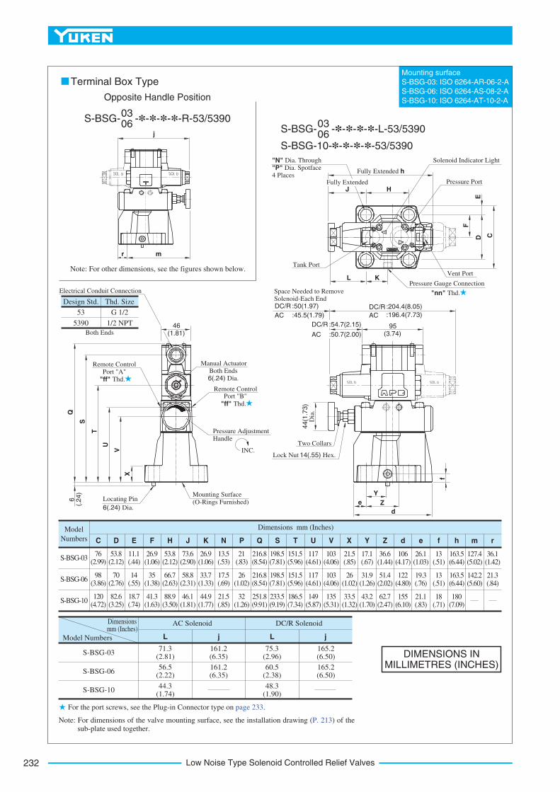
Low Noise Type Solenoid Controlled Relief Valves232
DIMENSIONS INMILLIMETRES (INCHES)
Mounting surface
S-BSG-03: ISO 6264-AR-06-2-A
S-BSG-06: ISO 6264-AS-08-2-A
S-BSG-10: ISO 6264-AT-10-2-A
71.3(2.81)
56.5(2.22)
44.3(1.74)
161.2(6.35)
161.2(6.35)
75.3(2.96)
60.5(2.38)
48.3(1.90)
165.2(6.50)
165.2(6.50)
S-BSG-03
S-BSG-06
S-BSG-10
Model Numbers
Dimensionsmm (Inches)
AC Solenoid
L j
DC/R Solenoid
L j
Model
Numbers
S-BSG-03
S-BSG-06
S-BSG-10
76(2.99)
98(3.86)
120(4.72)
53.8(2.12)
70(2.76)
82.6(3.25)
11.1(.44)
14(.55)
18.7(.74)
26.9(1.06)
35(1.38)
41.3(1.63)
53.8(2.12)
66.7(2.63)
88.9(3.50)
73.6(2.90)
58.8(2.31)
46.1(1.81)
26.9(1.06)
33.7(1.33)
44.9(1.77)
13.5(.53)
17.5(.69)
21.5(.85)
21(.83)
26(1.02)
32(1.26)
216.8(8.54)
216.8(8.54)
251.8(9.91)
198.5(7.81)
198.5(7.81)
233.5(9.19)
151.5(5.96)
151.5(5.96)
186.5(7.34)
117(4.61)
117(4.61)
149(5.87)
103(4.06)
103(4.06)
135(5.31)
21.5(.85)
26(1.02)
33.5(1.32)
17.1(.67)
31.9(1.26)
43.2(1.70)
36.6(1.44)
51.4(2.02)
62.7(2.47)
106(4.17)
122(4.80)
155(6.10)
26.1(1.03)
19.3(.76)
21.1(.83)
13(.51)
13(.51)
18(.71)
163.5(6.44)
163.5(6.44)
180(7.09)
127.4(5.02)
142.2(5.60)
36.1(1.42)
21.3(.84)
C D E F H J K N P Q S T U V X Y Z d e f h m r
Dimensions mm (Inches)
S-BSG- -*-*-*-*-R-53/539003 06
Opposite Handle Position
S-BSG- -*-*-*-*-L-53/539003 06
S-BSG-10-*-*-*-*-53/5390
For the port screws, see the Plug-in Connector type on page 233.
Terminal Box Type
Note: For other dimensions, see the figures shown below.
Note: For dimensions of the valve mounting surface, see the installation drawing (P. 213) of the sub-plate used together.
Design Std. Thd. Size
53 G 1/2
5390 1/2 NPT 46
(.24)
U
T
S
Q6 Locating Pin
6(.24) Dia.
Mounting Surface
(O-Rings Furnished)
INC.
Pressure Adjustment Handle
Remote Control Port "B"
"ff" Thd.
Remote Control Port "A"
"ff" Thd.
Manual Actuator Both Ends 6(.24) Dia.
Electrical Conduit Connection
Both Ends
V
X
"nn" Thd.
95(3.74)
DC/R
AC
:204.4(8.05)
:196.4(7.73)
DC/R
AC
:54.7(2.15)
:50.7(2.00)
DC/R
AC
:50(1.97)
:45.5(1.79)
Space Needed to Remove Solenoid-Each End
44(1
.73)
Dia
.
Two Collars
Lock Nut 14(.55)
e
d
Z
Y
Hex.
f
"N" Dia. Through
"P" Dia. Spotface 4 Places
JFully Extended
H
Fully Extended h
Solenoid Indicator Light
Pressure Port
E
Vent Port
F
D C
Pressure Gauge Connection L K
Tank Port
j
mr
(1.81)
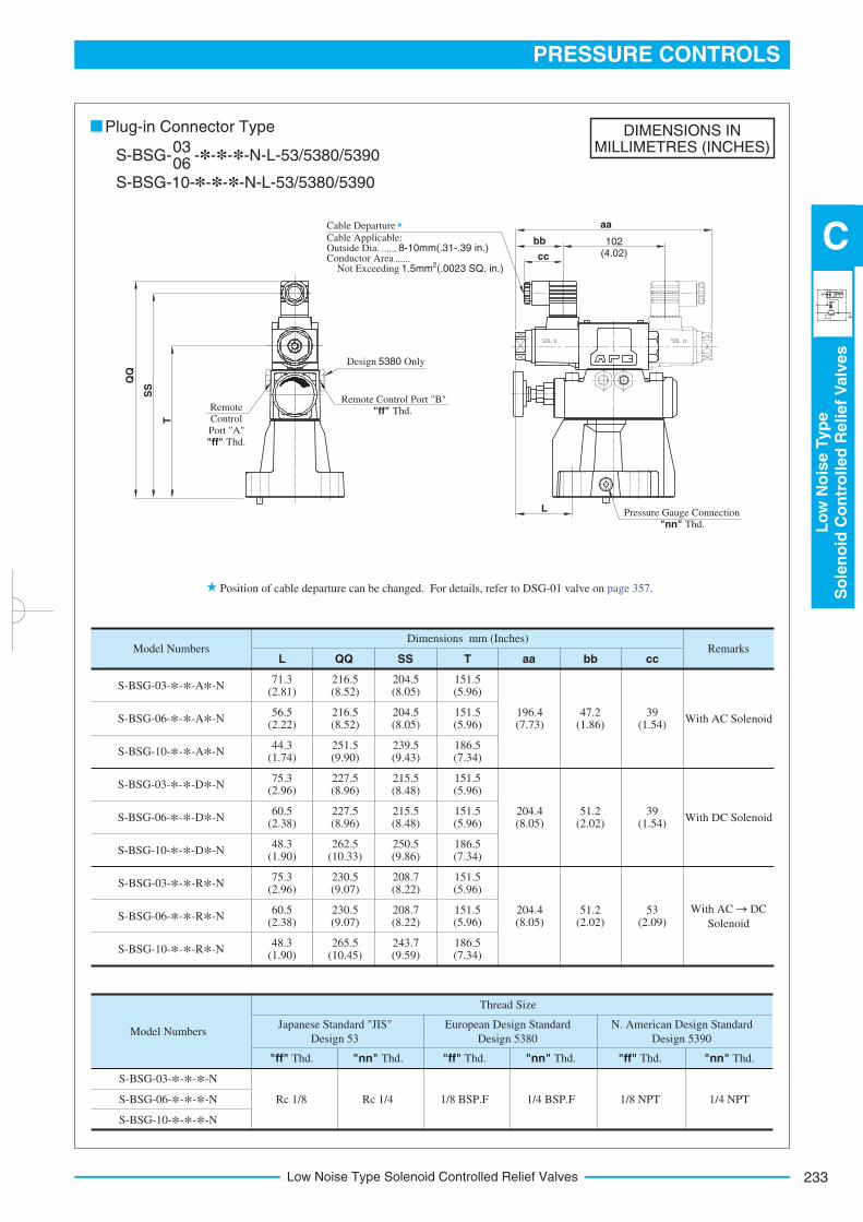
233
PRESSURE CONTROLS
Lo
wN
ois
eTyp
eS
ole
no
idC
on
tro
lled
Relief
Valv
es
C
Low Noise Type Solenoid Controlled Relief Valves
DIMENSIONS INMILLIMETRES (INCHES)
Model Numbers
S-BSG-03-*-*-A*-N
S-BSG-06-*-*-A*-N
S-BSG-10-*-*-A*-N
S-BSG-03-*-*-D*-N
S-BSG-06-*-*-D*-N
S-BSG-10-*-*-D*-N
S-BSG-03-*-*-R*-N
S-BSG-06-*-*-R*-N
S-BSG-10-*-*-R*-N
Dimensions mm (Inches)
LRemarks
SS TQQ aa bb cc
With AC Solenoid
With DC Solenoid
With AC DC
Solenoid
71.3(2.81)
216.5(8.52)
204.5(8.05)
151.5(5.96)
56.5(2.22)
216.5(8.52)
204.5(8.05)
151.5(5.96)
44.3(1.74)
251.5(9.90)
239.5(9.43)
186.5(7.34)
75.3(2.96)
227.5(8.96)
215.5(8.48)
151.5(5.96)
60.5(2.38)
227.5(8.96)
215.5(8.48)
151.5(5.96)
48.3(1.90)
262.5(10.33)
250.5(9.86)
186.5(7.34)
75.3(2.96)
230.5(9.07)
208.7(8.22)
151.5(5.96)
60.5(2.38)
230.5(9.07)
208.7(8.22)
151.5(5.96)
48.3(1.90)
265.5(10.45)
243.7(9.59)
186.5(7.34)
196.4(7.73)
47.2 (1.86)
39 (1.54)
204.4(8.05)
51.2(2.02)
39 (1.54)
204.4(8.05)
51.2(2.02)
53 (2.09)
Model Numbers
Rc 1/8
Japanese Standard "JIS"
Design 53
N. American Design Standard
Design 5390
"ff" Thd.
S-BSG-03-*-*-*-N
S-BSG-06-*-*-*-N
S-BSG-10-*-*-*-N
Rc 1/4 1/8 BSP.F
European Design Standard
Design 5380
"nn" Thd. "ff" Thd. "nn" Thd. "ff" Thd. "nn" Thd.
1/4 BSP.F 1/8 NPT 1/4 NPT
Thread Size
Plug-in Connector Type
S-BSG- -*-*-*-N-L-53/5380/539003 06
S-BSG-10-*-*-*-N-L-53/5380/5390
Position of cable departure can be changed. For details, refer to DSG-01 valve on page 357.
SS
T
Remote Control Port "B"
"ff" Thd. Remote Control
Port "A"
"ff" Thd.
Design 5380 Only
Cable Departure
Cable Applicable: Outside Dia. ...... 8-10mm(.31-.39 in.)Conductor Area ...... Not Exceeding 2 1.5mm (.0023 SQ. in.)
Pressure Gauge Connection
"nn" Thd.
L
cc
bb 102(4.02)
aa
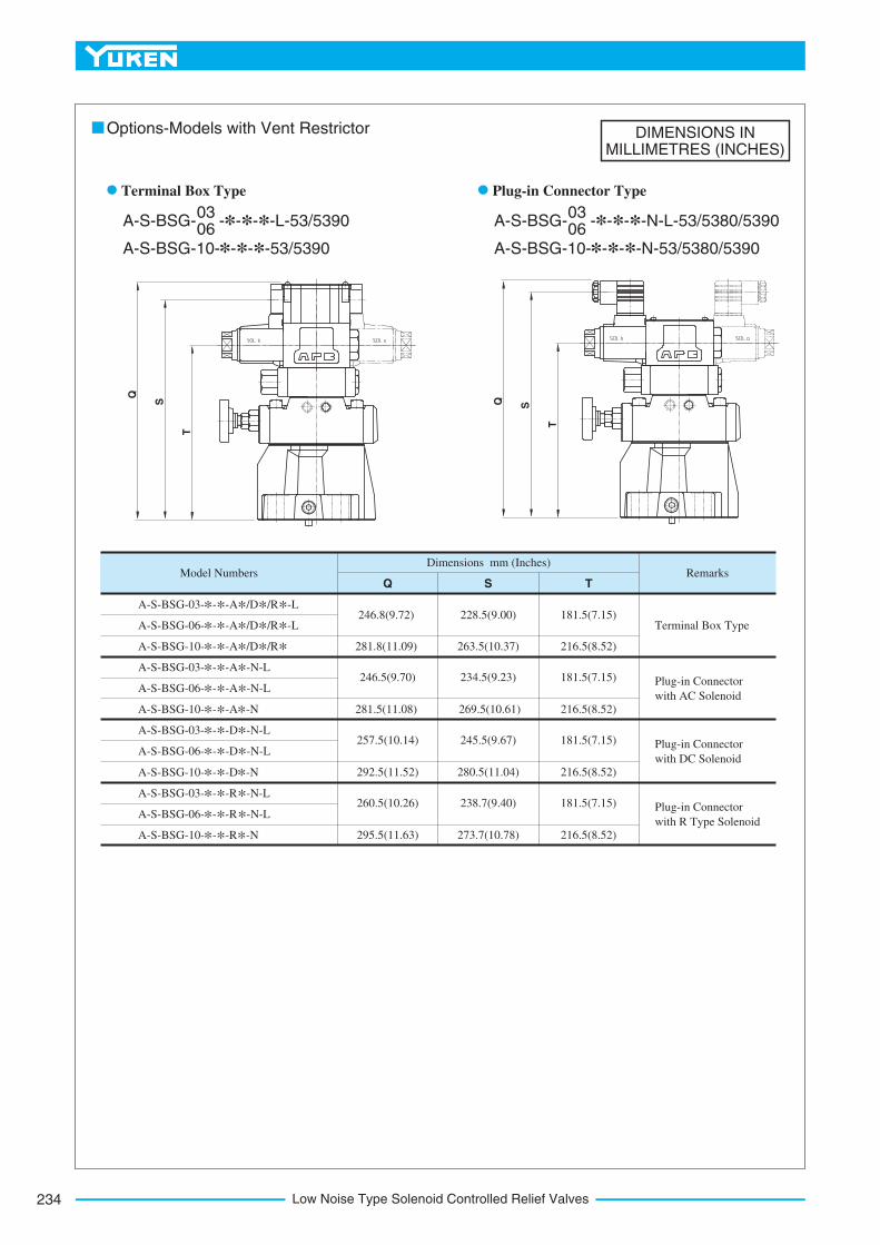
Low Noise Type Solenoid Controlled Relief Valves234
DIMENSIONS INMILLIMETRES (INCHES)
Model NumbersDimensions mm (Inches)
QRemarks
S T
A-S-BSG-03-*-*-A*/D*/R*-L
Terminal Box Type
Plug-in Connector
with DC Solenoid
Plug-in Connector
with R Type Solenoid
Plug-in Connector
with AC Solenoid
A-S-BSG-06-*-*-A*/D*/R*-L
A-S-BSG-10-*-*-A*/D*/R*A-S-BSG-03-*-*-A*-N-L
A-S-BSG-06-*-*-A*-N-L
A-S-BSG-10-*-*-A*-N
A-S-BSG-03-*-*-D*-N-L
A-S-BSG-06-*-*-D*-N-L
A-S-BSG-10-*-*-D*-N
A-S-BSG-03-*-*-R*-N -L
A-S-BSG-06-*-*-R*-N -L
A-S-BSG-10-*-*-R*-N
246.8(9.72)
281.8(11.09)
246.5(9.70)
281.5(11.08)
228.5(9.00)
263.5(10.37)
234.5(9.23)
269.5(10.61)
181.5(7.15)
216.5(8.52)
181.5(7.15)
216.5(8.52)
257.5(10.14)
292.5(11.52)
245.5(9.67)
280.5(11.04)
181.5(7.15)
216.5(8.52)
260.5(10.26)
295.5(11.63)
238.7(9.40)
273.7(10.78)
181.5(7.15)
216.5(8.52)
Options-Models with Vent Restrictor
A-S-BSG- -*-*-*-L-53/539003 06
A-S-BSG-10-*-*-*-53/5390
Terminal Box Type
A-S-BSG- -*-*-*-N-L-53/5380/539003 06
A-S-BSG-10-*-*-*-N-53/5380/5390
Plug-in Connector TypeT
S
Q
T
SQ
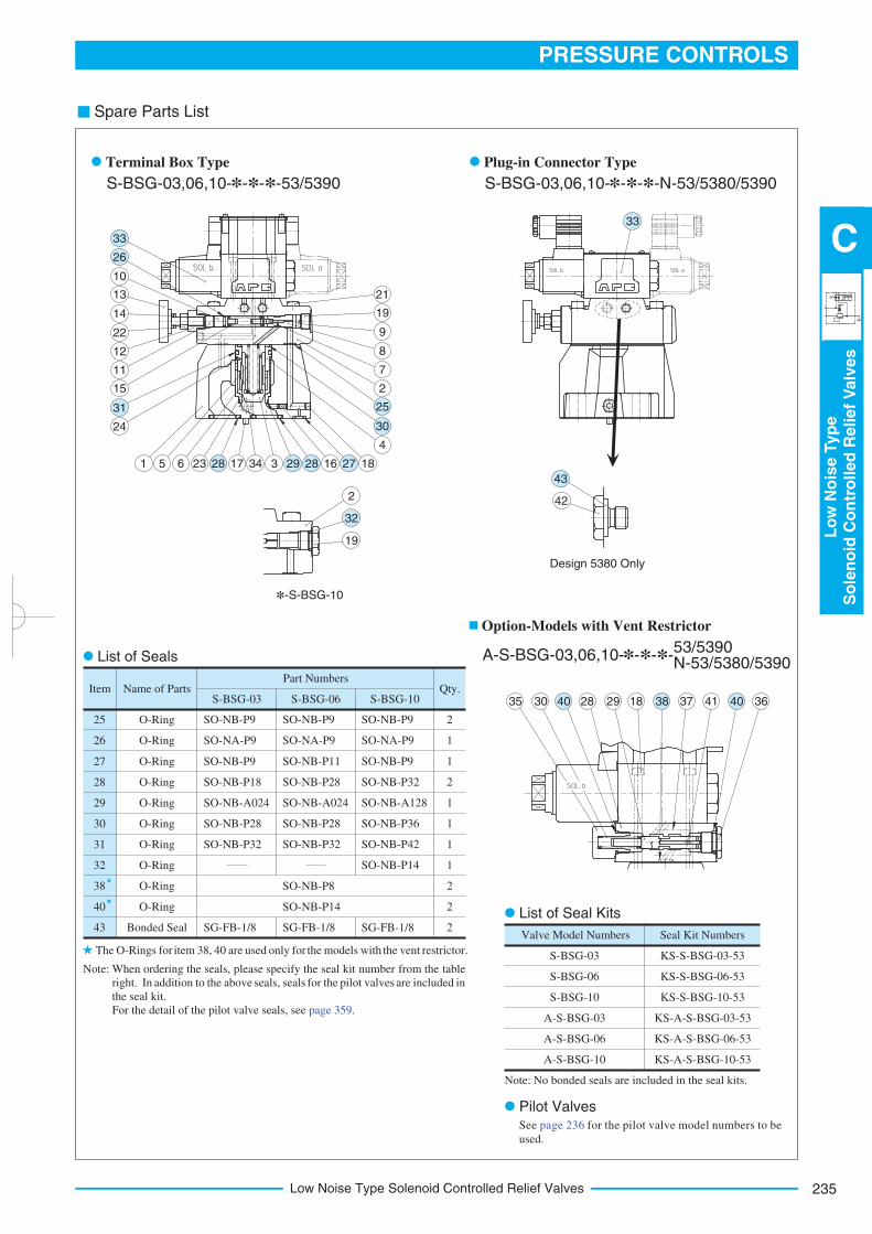
235
PRESSURE CONTROLS
Lo
wN
ois
eTyp
eS
ole
no
idC
on
tro
lled
Relief
Valv
es
C
Low Noise Type Solenoid Controlled Relief Valves
Spare Parts List
See page 236 for the pilot valve model numbers to be
used.
Valve Model Numbers Seal Kit Numbers
S-BSG-03
S-BSG-06
S-BSG-10
A-S-BSG-03
A-S-BSG-06
A-S-BSG-10
KS-S-BSG-03-53
KS-S-BSG-06-53
KS-S-BSG-10-53
KS-A-S-BSG-03-53
KS-A-S-BSG-06-53
KS-A-S-BSG-10-53
Item Name of PartsS-BSG-03 S-BSG-06 S-BSG-10
Qty.Part Numbers
25
26
27
28
29
30
31
32
38
40
43
O-Ring
O-Ring
O-Ring
O-Ring
O-Ring
O-Ring
O-Ring
O-Ring
O-Ring
O-Ring
Bonded Seal
SO-NB-P9
SO-NA-P9
SO-NB-P9
SO-NB-P18
SO-NB-A024
SO-NB-P28
SO-NB-P32
2
1
1
2
1
1
1
1
2
2
2SG-FB-1/8
SO-NB-P9
SO-NA-P9
SO-NB-P11
SO-NB-P28
SO-NB-A024
SO-NB-P28
SO-NB-P32
SG-FB-1/8
SO-NB-P9
SO-NA-P9
SO-NB-P9
SO-NB-P32
SO-NB-A128
SO-NB-P36
SO-NB-P42
SO-NB-P14
SG-FB-1/8
SO-NB-P8
SO-NB-P14
Terminal Box Type
S-BSG-03,06,10-*-*-*-53/5390
Plug-in Connector Type
S-BSG-03,06,10-*-*-*-N-53/5380/5390
Option-Models with Vent Restrictor
A-S-BSG-03,06,10-*-*-*53/5390 N-53/5380/5390
-
Note: No bonded seals are included in the seal kits.
List of Seal Kits
Pilot Valves
Note:
The O-Rings for item 38, 40 are used only for the models with the vent restrictor.
List of Seals
*-S-BSG-10
Design 5380 Only
When ordering the seals, please specify the seal kit number from the table
right. In addition to the above seals, seals for the pilot valves are included in
the seal kit.
For the detail of the pilot valve seals, see page 359.
2
19
10
13
14
22
12
11
15
24
21
42
19
9
8
7
2
4
1 5 6 23 17 34 3 16 18
32
33
26
31
33
43
25
30
28 29 28 27
35 30 28 29 37 41 361840 38 40
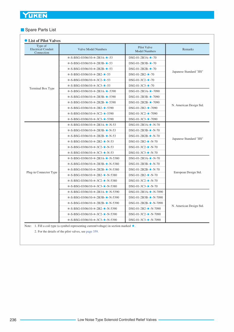
Low Noise Type Solenoid Controlled Relief Valves236
Spare Parts List
Type of Electrical Conduit
ConnectionValve Model Numbers
Pilot Valve
Model NumbersRemarks
Japanese Standard "JIS"
N. American Design Std.
N. American Design Std.
Japanese Standard "JIS"
European Design Std.
Terminal Box Type
Plug-in Connector Type
*-S-BSG-03/06/10-*-2B3A- -53
*-S-BSG-03/06/10-*-2B3B- -53
*-S-BSG-03/06/10-*-2B2B- -53
*-S-BSG-03/06/10-*-2B2- -53
*-S-BSG-03/06/10-*-3C2- -53
*-S-BSG-03/06/10-*-3C3- -53
*-S-BSG-03/06/10-*-2B3A- -5390
*-S-BSG-03/06/10-*-2B3B- -5390
*-S-BSG-03/06/10-*-2B2B- -5390
*-S-BSG-03/06/10-*-2B2- -5390
*-S-BSG-03/06/10-*-3C2- -5390
*-S-BSG-03/06/10-*-3C3- -5390
*-S-BSG-03/06/10-*-2B3A- -N-53
*-S-BSG-03/06/10-*-2B3B- -N-53
*-S-BSG-03/06/10-*-2B2B- -N-53
*-S-BSG-03/06/10-*-2B2- -N-53
*-S-BSG-03/06/10-*-3C2- -N-53
*-S-BSG-03/06/10-*-3C3- -N-53
*-S-BSG-03/06/10-*-2B3A- -N-5380
*-S-BSG-03/06/10-*-2B3B- -N-5380
*-S-BSG-03/06/10-*-2B2B- -N-5380
*-S-BSG-03/06/10-*-2B2- -N-5380
*-S-BSG-03/06/10-*-3C2- -N-5380
*-S-BSG-03/06/10-*-3C3- -N-5380
*-S-BSG-03/06/10-*-2B3A- -N-5390
*-S-BSG-03/06/10-*-2B3B- -N-5390
*-S-BSG-03/06/10-*-2B2B- -N-5390
*-S-BSG-03/06/10-*-2B2- -N-5390
*-S-BSG-03/06/10-*-3C2- -N-5390
*-S-BSG-03/06/10-*-3C3- -N-5390
DSG-01-2B3A- -70
DSG-01-2B3B- -70
DSG-01-2B2B- -70
DSG-01-2B2- -70
DSG-01-3C2- -70
DSG-01-3C3- -70
DSG-01-2B3A- -7090
DSG-01-2B3B- -7090
DSG-01-2B2B- -7090
DSG-01-2B2- -7090
DSG-01-3C2- -7090
DSG-01-3C3- -7090
DSG-01-2B3A- -N-70
DSG-01-2B3B- -N-70
DSG-01-2B2B- -N-70
DSG-01-2B2- -N-70
DSG-01-3C2- -N-70
DSG-01-3C3- -N-70
DSG-01-2B3A- -N-70
DSG-01-2B3B- -N-70
DSG-01-2B2B- -N-70
DSG-01-2B2- -N-70
DSG-01-3C2- -N-70
DSG-01-3C3- -N-70
DSG-01-2B3A- -N-7090
DSG-01-2B3B- -N-7090
DSG-01-2B2B- -N-7090
DSG-01-2B2- -N-7090
DSG-01-3C2- -N-7090
DSG-01-3C3- -N-7090
List of Pilot Valves
Fill a coil type (a symbol representing current/voltage) in section marked .Note: 1.
For the details of the pilot valves, see page 359.2.
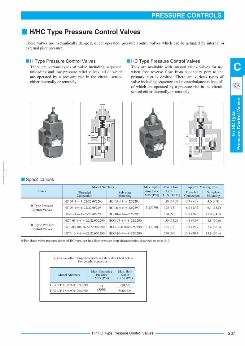
237
PRESSURE CONTROLS
H/H
CTyp
eP
ressu
reC
on
tro
lV
alv
es
C
H / HC Type Pressure Control Valves
H/HC Type Pressure Control Valves
These valves are hydraulically damped, direct operated, pressure control valves which can be actuated by internal or
external pilot pressure.
H Type Pressure Control Valves HC Type Pressure Control Valves
There are various types of valve including sequence,
unloading and low pressure relief valves, all of which
are operated by a pressure rise in the circuit, sensed
either internally or remotely.
They are available with integral check valves for use
when free reverse flow from secondary port to the
primary port is desired. There are various types of
valve including sequence and counterbalance valves, all
of which are operated by a pressure rise in the circuit,
sensed either internally or remotely.
Approx. Mass kg (lbs.)
Threaded Connection
Sub-plate Mounting
Model Numbers
Threaded Connection
Sub-plate Mounting
HG-03-**-*-22/2290
Max. Oper-
ating Pres.
MPa (PSI)
HT-03-**-*-22/2280/2290
HT-06-**-*-22/2280/2290
HT-10-**-*-22/2280/2290
HCT-03-**-*-22/2280/2290
HCT-06-**-*-22/2280/2290
HCT-10-**-*-22/2280/2290
H Type Pressure
Control Valves
HC Type Pressure
Control Valves
21(3050)
21(3050)
Max. Flow
L/min
(U.S .GPM)
50
HG-06-**-*-22/2290
HG-10-**-*-22/2290
HCG-03-**-*-22/2290
HCG-06-**-*-22/2290
HCG-10-**-*-22/2290
(13.2)
125 (33)
250 (66)
50 (13.2)
125 (33)
250 (66)
3.7 (8.2)
6.2 (13.7)
12.0 (26.5)
4.1 (9.0)
7.1 (15.7)
13.8 (30.4)
4.0 (8.8)
6.1 (13.5)
11.0 (24.3)
4.8 (10.6)
7.4 (16.3)
13.8 (30.4)
Model NumbersMax. Operating
Pressure MPa (PSI)
Max. flow L/min
(U.S.GPM)
HF/HCF-10-**-*-22/2290
HF/HCF-16-**-*-20/2090
21 (3050)
250(66)
500(132)
Series
Specifications
For check valve pressure drops of HC type, see free flow pressure drop characteristics described on page 247.
Yuken can offer flanged connection valves described below. For details, contact us.
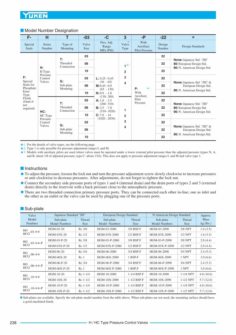
H / HC Type Pressure Control Valves238
3
2
1
1.
3.
2.
For the details of valve types, see the following page.
F:
Special Seals for Phosphate Ester Type Fluids (Omit if not required)
Special
Seals
F-
H:
H Type Pressure Control Valves
03
T
Type of
Mounting
Valve
Size
Pres. Adj.
Range
MPa (PSI)
Design Standards
-C *-03
None: Japanese Std. "JIS"
80: European Design Std.
90: N. American Design Std.
-22
Design
Number
L: 0.25
Model Number Designation
H
Series
Number
06
10
03
06
10
03
06
10
03
06
10
- 0.45(36 - 65)
M:0.45 - 0.9(65 - 130)
N: 0.9 - 1.8(130- 260)
A: 1.8 - 3.5(260- 510)
B: 3.5 - 7.0(510- 1020)
C: 7.0 - 14(1020 - 2030)
3
Valve
Type
-PWith
Auxiliary
Pilot Pressure
22
22
22
22
22
22
22
22
22
22
22
22
1
2
3
4
1
2
3
4
HC:
HC Type Pressure Control Valves
T:
Threaded Connection
G:
Sub-plate Mounting
T:
Threaded Connection
G:
Sub-plate Mounting
P:
With Auxiliary Pilot Pressure
None: Japanese Std. "JIS" & European Design Std.
90: N. American Design Std.
None: Japanese Std. "JIS"
80: European Design Std.
90: N. American Design Std.
None: Japanese Std. "JIS" & European Design Std.
90: N. American Design Std.
Type 1 is only possible for pressure adjustment ranges L and M.
Models with auxiliary pilots are used where valves must be operated under a lower external pilot pressure than the adjusted pressure (types N, A,
and B: about 1/8 of adjusted pressure; type C: about 1/16). This does not apply to pressure adjustment ranges L and M and valve type 1.
Valve
Model
Numbers
-03-**HG HCG
-03-**-PHG HCG
-06-**HG HCG
HG HCG
-10-**HG HCG
HG HCG
Rc 3/8
Rc 1/2
Rc 3/8
Rc 1/2
Rc 3/4
Rc 1
Rc 3/4
Rc 1
Rc 1-1/4
Rc 1-1/2
Rc 1-1/4
Rc 1-1/2
-06-**-P
-10-**-P
Sub-plate
Model Numbers
Thread
Size
Japanese Standard "JIS"
HGM-03-20
HGM-03X-20
HGM-03-P-20
HGM-03X-P-20
HGM-06-20
HGM-06X-20
HGM-06-P-20
HGM-06X-P-20
HGM-10-20
HGM-10X-20
HGM-10-P-20
HGM-10X-P-20
3/8 BSP.F
Sub-plate
Model Numbers
Thread
Size
European Design Standard
HGM-03-2080
HGM-03X-2080
HGM-03-P-2080
HGM-03X-P-2080
HGM-06-2080
HGM-06X-2080
HGM-06-P-2080
HGM-06X-P-2080
HGM-10-2080
HGM-10X-2080
HGM-10-P-2080
HGM-10X-P-2080
3/8 NPT
Sub-plate
Model Numbers
Thread
Size
N.American Design Standard
HGM-03-2090
HGM-03X-2090
HGM-03-P-2090
HGM-03X-P-2090
HGM-06-2090
HGM-06X-2090
HGM-06-P-2090
HGM-06X-P-2090
HGM-10-2090
HGM-10X-2090
HGM-10-P-2090
HGM-10X-P-2090
1/2 BSP.F
3/8 BSP.F
1/2 BSP.F
3/4 BSP.F
1 BSP.F
3/4 BSP.F
1 BSP.F
1-1/4 BSP.F
1-1/2 BSP.F
1-1/4 BSP.F
1-1/2 BSP.F
1/2 NPT
3/8 NPT
1/2 NPT
3/4 NPT
1 NPT
3/4 NPT
1 NPT
1-1/4 NPT
1-1/2 NPT
1-1/4 NPT
1-1/2 NPT
Approx.
Mass
kg (lbs.)
1.6 (3.5)
1.6 (3.5)
2.0 (4.4)
2.0 (4.4)
2.4 (5.3)
3.0 (6.6)
2.4 (5.3)
3.0 (6.6)
4.8 (10.6)
5.7 (12.6)
4.8 (10.6)
5.7 (12.6)
Instructions
Sub-plate
To adjust the pressure, loosen the lock nut and turn the pressure adjustment screw slowly clockwise to increase pressures or anti-clockwise to decrease pressures. After adjustments, do not forget to tighten the lock nut.
Connect the secondary side pressure ports of types 1 and 4 (internal drain) and the drain ports of types 2 and 3 (external drain) directly to the reservoir with a back pressure close to the atmospheric pressure.
There are two threaded connection primary pressure ports. They can be connected each other in-line; one as inlet and the other as an outlet or the valve can be used by plugging one of the pressure ports.
Sub-plates are available. Specify the sub-plate model number from the table above. When sub-plates are not used, the mounting surface should have
a good machined finish.
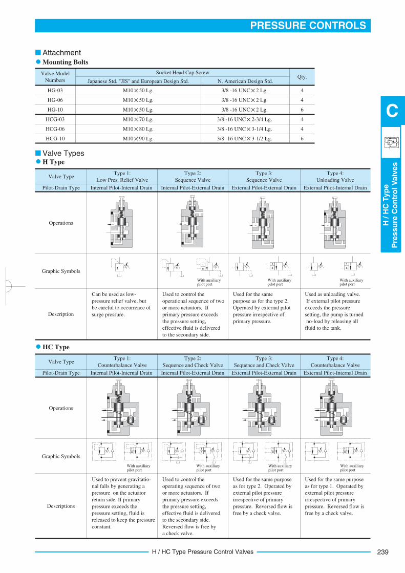
239
PRESSURE CONTROLS
H/H
CTyp
eP
ressu
reC
on
tro
lV
alv
es
C
H / HC Type Pressure Control Valves
Valve Model
Numbers
Socket Head Cap Screw
Japanese Std. "JIS" and European Design Std. N. American Design Std.
HG-03 3/8 -16 UNC 2 Lg. 4M10 50 Lg.
Qty.
HG-06
HG-10
HCG-03
HCG-06
HCG-10
M10 50 Lg.
M10 50 Lg.
M10 70 Lg.
M10 80 Lg.
M10 90 Lg.
4
6
4
4
6
3/8 -16 UNC 2 Lg.
3/8 -16 UNC 2 Lg.
3/8 -16 UNC 2-3/4 Lg.
3/8 -16 UNC 3-1/4 Lg.
3/8 -16 UNC 3-1/2 Lg.
Attachment
Mounting Bolts
Valve Type
Pilot-Drain Type
Type 1:
Low Pres. Relief Valve
Internal Pilot-Internal Drain
Type 2:
Sequence Valve
Internal Pilot-External Drain
Type 3:
Sequence Valve
External Pilot-External Drain
Type 4:
Unloading Valve
External Pilot-Internal Drain
Operations
Graphic Symbols
Description
Can be used as low-
pressure relief valve, but
be careful to occurrence of
surge pressure.
Used to control the
operational sequence of two
or more actuators. If
primary pressure exceeds
the pressure setting,
effective fluid is delivered
to the secondary side.
Used for the same
purpose as for the type 2.
Operated by external pilot
pressure irrespective of
primary pressure.
Used as unloading valve.
If external pilot pressure
exceeds the pressure
setting, the pump is turned
no-load by releasing all
fluid to the tank.
With auxiliary pilot port
With auxiliary pilot port
With auxiliary pilot port
Valve TypesH Type
Valve Type
Pilot-Drain Type
Type 1:
Counterbalance Valve
Internal Pilot-Internal Drain
Type 2:
Sequence and Check Valve
Internal Pilot-External Drain
Type 3:
Sequence and Check Valve
External Pilot-External Drain
Type 4:
Counterbalance Valve
External Pilot-Internal Drain
Operations
Graphic Symbols
Descriptions
Used to prevent gravitatio-
nal falls by generating a
pressure on the actuator
return side. If primary
pressure exceeds the
pressure setting, fluid is
released to keep the pressure
constant.
Used to control the
operating sequence of two
or more actuators. If
primary pressure exceeds
the pressure setting,
effective fluid is delivered
to the secondary side.
Reversed flow is free by
a check valve.
Used for the same purpose
as for type 2. Operated by
external pilot pressure
irrespective of primary
pressure. Reversed flow is
free by a check valve.
Used for the same purpose
as for type 1. Operated by
external pilot pressure
irrespective of primary
pressure. Reversed flow is
free by a check valve.
With auxiliarypilot port
With auxiliarypilot port
With auxiliarypilot port
With auxiliarypilot port
1
8
1
8
1
8
1
8
HC Type
1
8
1
8
1
8
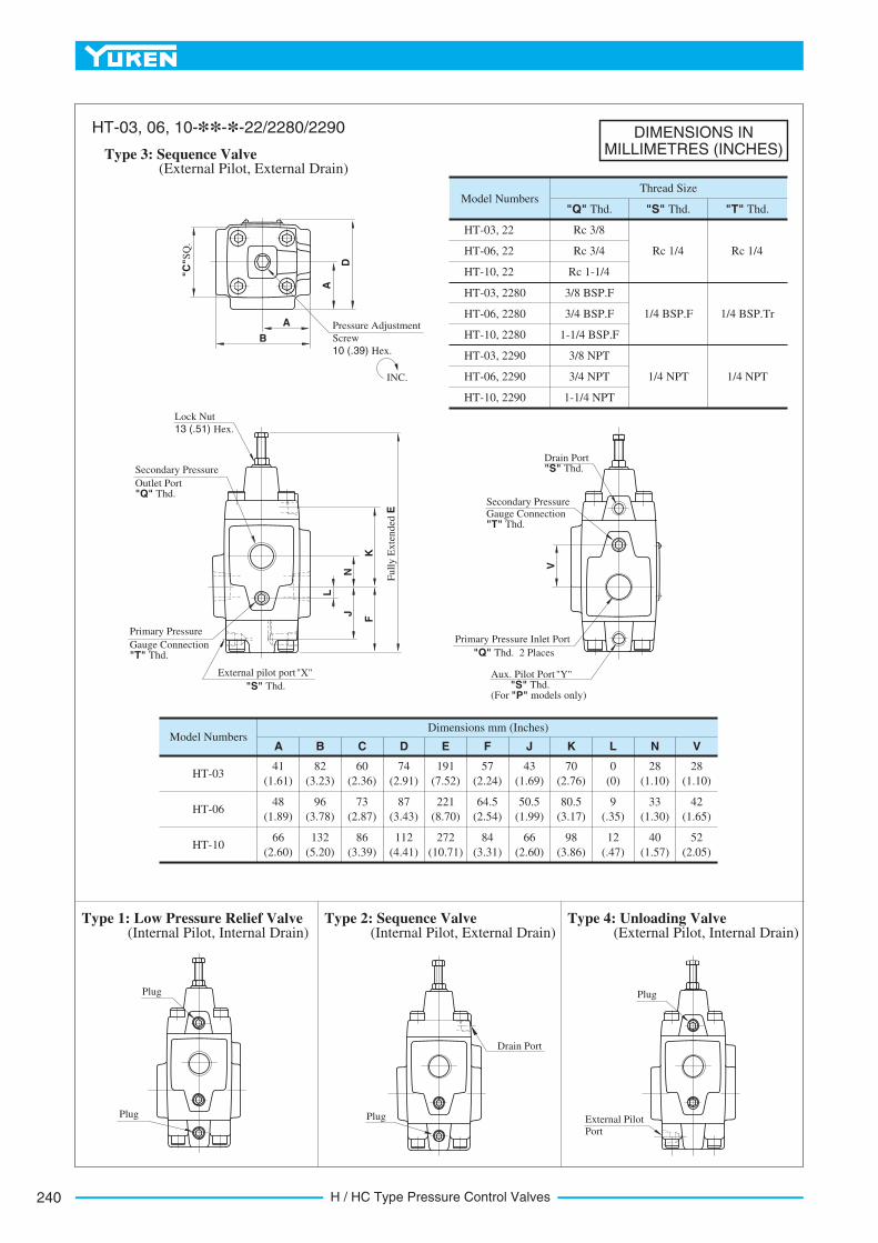
H / HC Type Pressure Control Valves240
DIMENSIONS INMILLIMETRES (INCHES)
Model Numbers"Q" Thd. "S" Thd.
Thread Size
"T" Thd.
HT-03, 22
HT-06, 22
HT-10, 22
HT-03, 2280
HT-06, 2280
HT-10, 2280
HT-03, 2290
HT-06, 2290
HT-10, 2290
Rc 3/8
Rc 3/4
Rc 1-1/4
3/8 BSP.F
3/8 NPT
3/4 BSP.F
1-1/4 BSP.F
3/4 NPT
1-1/4 NPT
Rc 1/4
1/4 BSP.F
1/4 NPT
Rc 1/4
1/4 BSP.Tr
1/4 NPT
Model Numbers
HT-03
HT-06
HT-10
41
(1.61)
48
(1.89)
66
(2.60)
A
82
(3.23)
96
(3.78)
132
(5.20)
B
60
(2.36)
73
(2.87)
86
(3.39)
C
74
(2.91)
87
(3.43)
112
(4.41)
D
191
(7.52)
221
(8.70)
272
(10.71)
E
57
(2.24)
64.5
(2.54)
84
(3.31)
F
43
(1.69)
50.5
(1.99)
66
(2.60)
J
70
(2.76)
80.5
(3.17)
98
(3.86)
K
0
(0)
9
(.35)
12
(.47)
L
28
(1.10)
33
(1.30)
40
(1.57)
N
28
(1.10)
42
(1.65)
52
(2.05)
V
Dimensions mm (Inches)
Type 3: Sequence Valve
HT-03, 06, 10-**-*-22/2280/2290
(External Pilot, External Drain)
Type 1: Low Pressure Relief Valve(Internal Pilot, Internal Drain)
Type 2: Sequence Valve(Internal Pilot, External Drain)
Type 4: Unloading Valve(External Pilot, Internal Drain)
A
D
A
B
"C"S
Q.
Pressure Adjustment
Screw
10 (.39) Hex.
Lock Nut
13 (.51) Hex.
N
L
K
J
F
Full
y E
xte
nded
E
Secondary Pressure
Outlet Port "Q" Thd.
Primary Pressure
Gauge Connection "T" Thd.
External pilot port "X"
"S" Thd.
V
Drain Port "S" Thd.
Secondary Pressure
Gauge Connection "T" Thd.
Primary Pressure Inlet Port
"Q" Thd. 2 Places
Aux. Pilot Port "Y""S" Thd.
(For "P" models only)
Plug
Plug Plug
Drain Port
Plug
External Pilot
Port
INC.

241
PRESSURE CONTROLS
H/H
CTyp
eP
ressu
reC
on
tro
lV
alv
es
C
H / HC Type Pressure Control Valves
DIMENSIONS INMILLIMETRES (INCHES)
Mounting Surface
HG-03: ISO 5781-AG-06-2-A
HG-06: ISO 5781-AH-08-2-A
Mounting Surface
ISO 5781-AJ-10-2-A
Model Numbers
HG-0360
(2.36)
A
HG-0673
(2.87)
67
(2.64)
B
79
(3.11)
35
(1.38)
C
40
(1.57)
39
(1.54)
D
39
(1.54)
89
(3.50)
E
102
(4.02)
191
(7.52)
F
221
(8.70)
49.6
(1.95)
J
51
(2.01)
38
(1.50)
K
38
(1.50)
Dimensions mm (Inches)
External Pilot Port
Drain Port
External Pilot Port
Drain Port
C
B
"A" SQ.
6(.24)
K
Full
y E
xte
nded
F
Lock Nut
13 (.51) Hex.
Drain Port
Secondary Pressure
Outlet Port
Pressure Adjustment Screw
10 (.39) Hex.
11(.43) Dia. Through
17.5(.69) Dia. Spotface 4 Places
External Pilot Port "X"
Primary Pressure
Inlet PortAux. Pilot Port "Y"(For "P" models only)
Locating Pin
6(.24) Dia.
Mounting Surface
(O-Rings Furnished)
86(3.39) SQ.
6 (.24)
46
(1.8
1)
92
(3.6
2)
39
(1.5
4)
Pressure Adjustment Screw
10(.39) Hex.
Lock Nut 13(.51) Hex.
Secondary Pressure
Outlet Port
11(.43) Dia. Through
17.5(.69) Dia. Spotface 4 Places
External Pilot Port "X"
Primary Pressure Inlet Port
Aux. Pilot Port "Y"(For "P" models only)
Drain Port
Locating Pin
6(.24) Dia.
Mounting Surface
(O-Rings Furnished)
38
(1.50) 119
(4.69)
E
J
62
(2.4
4)
Full
y E
xte
nded
272(1
0.7
1)
D
Type 3: Sequence Valve
HG-03, 06-**-*-22/2290
(External Pilot, External Drain)
(Internal Pilot, Internal Drain)
Type 1: Low Pressure Relief Valve
(Internal Pilot, External Drain)
Type 2: Sequence Valve
(External Pilot, Internal Drain)Type 4: Unloading Valve
(Internal Pilot, Internal Drain)Type 1: Low Pressure Relief Valve
(Internal Pilot, External Drain)Type 2: Sequence Valve
(External Pilot, Internal Drain)
Type 4: Unloading Valve
Type 3: Sequence Valve
HG-10-**-*-22/2290
(External Pilot, External Drain)
INC.
INC.
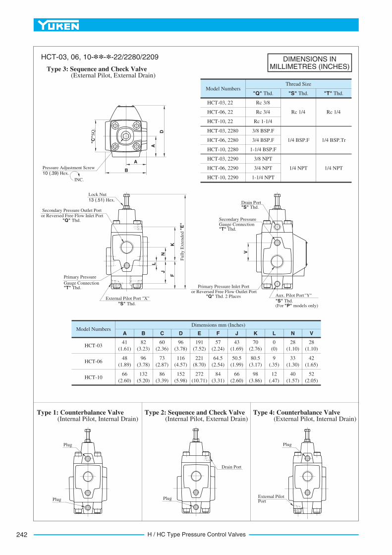
H / HC Type Pressure Control Valves242
DIMENSIONS INMILLIMETRES (INCHES)
Model Numbers
HCT-03
HCT-06
HCT-10
41
(1.61)
48
(1.89)
66
(2.60)
A
82
(3.23)
96
(3.78)
132
(5.20)
B
60
(2.36)
73
(2.87)
86
(3.39)
C
96
(3.78)
116
(4.57)
152
(5.98)
D
191
(7.52)
221
(8.70)
272
(10.71)
E
57
(2.24)
64.5
(2.54)
84
(3.31)
F
43
(1.69)
50.5
(1.99)
66
(2.60)
J
70
(2.76)
80.5
(3.17)
98
(3.86)
K
0
(0)
9
(.35)
12
(.47)
L
28
(1.10)
33
(1.30)
40
(1.57)
N
28
(1.10)
42
(1.65)
52
(2.05)
V
Dimensions mm (Inches)
External Pilot Port "X"
"S" Thd.
Lock Nut
13 (.51) Hex.
Secondary Pressure Outlet Port
or Reversed Free Flow Inlet Port "Q" Thd.
Primary Pressure
Gauge Connection "T" Thd.
Drain Port "S" Thd.
"S" Thd.
V
Secondary Pressure Gauge Connection "T" Thd.
Full
y E
xte
nded
"E
"
A
DA
B
"C"S
Q.
N
K
J
F
L
Primary Pressure Inlet Port or Reversed Free Flow Outlet Port
"Q" Thd. 2 Places Aux. Pilot Port "Y"
(For "P" models only)
Type 3: Sequence and Check Valve
HCT-03, 06, 10-**-*-22/2280/2209
(External Pilot, External Drain)
Pressure Adjustment Screw
10 (.39) Hex.
Model Numbers"Q" Thd. "S" Thd.
Thread Size
"T" Thd.
HCT-03, 22
HCT-06, 22
HCT-10, 22
HCT-03, 2280
HCT-06, 2280
HCT-10, 2280
HCT-03, 2290
HCT-06, 2290
HCT-10, 2290
Rc 3/8
Rc 3/4
Rc 1-1/4
3/8 BSP.F
3/8 NPT
3/4 BSP.F
1-1/4 BSP.F
3/4 NPT
1-1/4 NPT
Rc 1/4
1/4 BSP.F
1/4 NPT
Rc 1/4
1/4 BSP.Tr
1/4 NPT
Plug
Plug
Type 1: Counterbalance Valve(Internal Pilot, Internal Drain)
Plug
Drain Port
Type 2: Sequence and Check Valve(Internal Pilot, External Drain)
Plug
External Pilot Port
Type 4: Counterbalance Valve(External Pilot, Internal Drain)
INC.
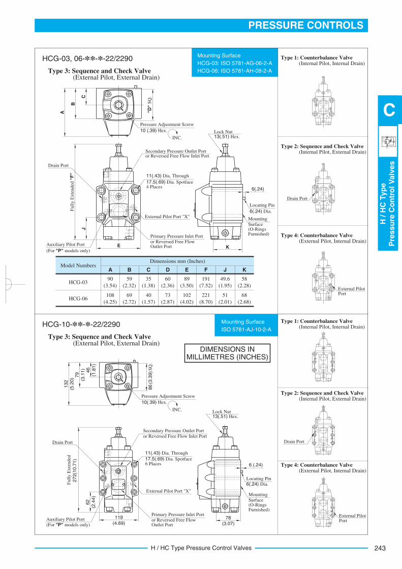
243
PRESSURE CONTROLS
H/H
CTyp
eP
ressu
reC
on
tro
lV
alv
es
C
H / HC Type Pressure Control Valves
DIMENSIONS INMILLIMETRES (INCHES)
Mounting Surface
HCG-03: ISO 5781-AG-06-2-A
HCG-06: ISO 5781-AH-08-2-A
Mounting Surface
ISO 5781-AJ-10-2-A
Model Numbers
HCG-0390
(3.54)
A
HCG-06108
(4.25)
59
(2.32)
B
69
(2.72)
35
(1.38)
C
40
(1.57)
60
(2.36)
D
73
(2.87)
89
(3.50)
E
102
(4.02)
191
(7.52)
F
221
(8.70)
49.6
(1.95)
J
51
(2.01)
58
(2.28)
K
68
(2.68)
Dimensions mm (Inches)
6(.24)
"D"
SQ
.
External Pilot Port
Drain Port
External Pilot Port
Drain Port
Drain Port
Secondary Pressure Outlet Port or Reversed Free Flow Inlet Port
Pressure Adjustment Screw
10 (.39) Hex.
11(.43) Dia. Through
17.5(.69) Dia. Spotface 4 Places
External Pilot Port "X"
Primary Pressure Inlet Port
or Reversed Free Flow Outlet PortAuxiliary Pilot Port
(For "P" models only)
Locating Pin
6(.24) Dia.
Mounting
Surface (O-Rings Furnished)
6 (.24)
Pressure Adjustment Screw
10(.39) Hex.
Lock Nut 13(.51) Hex.
Secondary Pressure Outlet Port
or Reversed Free Flow Inlet Port
11(.43) Dia. Through
17.5(.69) Dia. Spotface 6 Places
External Pilot Port "X"
Primary Pressure Inlet Port
or Reversed Free Flow Outlet Port
Auxiliary Pilot Port
(For "P" models only)
Drain Port
Locating Pin
6(.24) Dia.
Mounting
Surface (O-Rings Furnished)
78(3.07)
K
Lock Nut 13(.51) Hex.
E
JC
B
A
119
(4.69)
62
(2.4
4)
132
(5.2
0) 7
9
(3.1
1)
46
(1.8
1)
Full
y E
xte
nded
"F
"
86 (3
.39) S
Q.
Full
y E
xte
nded
272(1
0.7
1)
Type 3: Sequence and Check Valve
HCG-03, 06-**-*-22/2290
(External Pilot, External Drain)
Type 1: Counterbalance Valve(Internal Pilot, Internal Drain)
Type 3: Sequence and Check Valve
HCG-10-**-*-22/2290
(External Pilot, External Drain)
Type 2: Sequence and Check Valve(Internal Pilot, External Drain)
Type 4: Counterbalance Valve(External Pilot, Internal Drain)
Type 1: Counterbalance Valve(Internal Pilot, Internal Drain)
Type 2: Sequence and Check Valve(Internal Pilot, External Drain)
Type 4: Counterbalance Valve(External Pilot, Internal Drain)
INC.
INC.
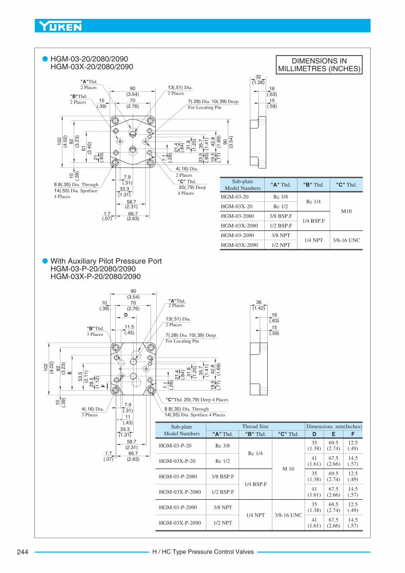
H / HC Type Pressure Control Valves244
DIMENSIONS INMILLIMETRES (INCHES)
HGM-03-20 Rc 3/8Rc 1/4
M10Rc 1/2
3/8 BSP.F
1/2 BSP.F
3/8 NPT
1/2 NPT
1/4 BSP.F
1/4 NPT 3/8-16 UNC
Sub-plate
Model Numbers
HGM-03X-20
HGM-03-2080
HGM-03-2090
HGM-03X-2090
HGM-03X-2080
"A" Thd. "B" Thd. "C" Thd.
Sub-plate
Model Numbers
HGM-03-P-20
HGM-03X-P-20
HGM-03-P-2080
HGM-03X-P-2080
HGM-03-P-2090
HGM-03X-P-2090
Rc 3/8
Rc 1/4
M 10
35 (1.38)
"A" Thd. "B" Thd. "C" Thd. D E
Thread Size Dimensions mm(Inches)
F
69.5 (2.74)
12.5 (.49)
41 (1.61)
67.5 (2.66)
14.5 (.57)
35 (1.38)
69.5 (2.74)
12.5 (.49)
41 (1.61)
67.5 (2.66)
14.5 (.57)
35 (1.38)
69.5 (2.74)
12.5 (.49)
41 (1.61)
67.5 (2.66)
14.5 (.57)
Rc 1/2
3/8 BSP.F
1/2 BSP.F
3/8 NPT
1/2 NPT
1/4 BSP.F
1/4 NPT 3/8-16 UNC
70
(2.76)
10
(.39)
61
(2.4
0)
21
(.83)
82
(3.2
3)
102
(4.0
2)
10
(.39)
7.9
(.31)
33.3
(1.31)
58.7 (2.31)
66.7 (2.63)
1.7 (.07)
7.1
(.28) 2
1.4
(.84)
31.8
(1.2
5)
35.7
(1.4
1)
42.8
(1.6
9)
90
(3.5
4)
19.5
(.77)
23.5
(.93)
90
(3.54)
32 (1.26)
16
(.63)
13(.51) Dia.
2 Places
7(.28) Dia. 10(.39) Deep
For Locating Pin
"A"Thd.
2 Places
"B"Thd.
2 Places
4(.16) Dia.
2 Places
"C" Thd.
20(.79) Deep
4 Places
8.8(.35) Dia. Through
14(.55) Dia. Spotface
4 Places
90
(3.54)
70 (2.76)
10 (.39)
D
11.5
(.45)
F28.5
(1.1
2)
53.5
(2.1
1)
E
82
(3.2
3)
10
(.39)
102
(4.0
2)
7.9
(.31)
11
(.43)
33.3
(1.31)
58.7
(2.31)
66.7 (2.63)
1.7
(.07)
7.1
(.28) 2
1.4
(.84)
31.8
(1.2
5)
35.7
(1.4
1)
42.8
(1.6
9)
19.5
(.77)
36
(1.42)
16
(.63)
"A"Thd. 2 Places
13(.51) Dia.
2 Places
7(.28) Dia. 10(.39) Deep
For Locating Pin
"B"Thd.
3 Places
4(.16) Dia.
3 Places
"C"Thd. 20(.79) Deep 4 Places
8.8(.35) Dia. Through
14(.55) Dia. Spotface 4 Places
HGM-03-20/2080/2090 HGM-03X-20/2080/2090
With Auxiliary Pilot Pressure Port HGM-03-P-20/2080/2090 HGM-03X-P-20/2080/2090
15
(.59)
15
(.59)
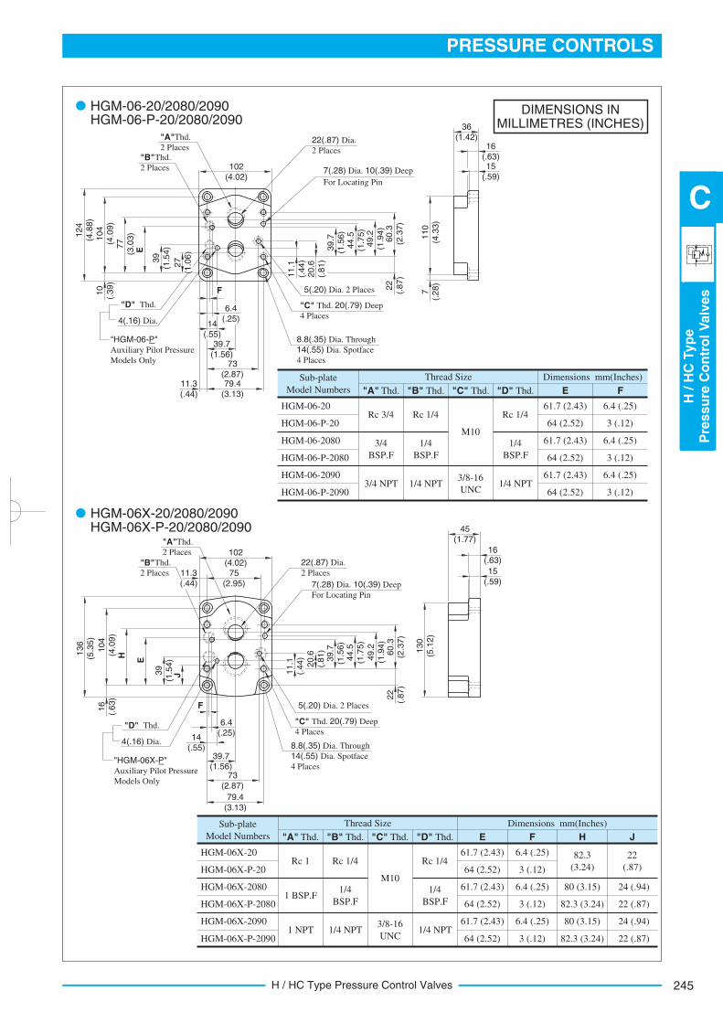
245
PRESSURE CONTROLS
H/H
CTyp
eP
ressu
reC
on
tro
lV
alv
es
C
H / HC Type Pressure Control Valves
DIMENSIONS INMILLIMETRES (INCHES)
Sub-plate
Model Numbers
HGM-06-20
HGM-06-P-20
HGM-06-2080
HGM-06-P-2080
HGM-06-2090
HGM-06-P-2090
Rc 3/4
3/4
BSP.F
3/4 NPT
Rc 1/4
1/4
BSP.F
1/4 NPT
M10
3/8-16
UNC
Rc 1/4
1/4
BSP.F
1/4 NPT
61.7 (2.43)
64 (2.52)
61.7 (2.43)
64 (2.52)
61.7 (2.43)
64 (2.52)
6.4 (.25)
3 (.12)
6.4 (.25)
3 (.12)
6.4 (.25)
3 (.12)
"A" Thd. "B" Thd. "C" Thd. "D" Thd. E F
Thread Size Dimensions mm(Inches)
Sub-plate
Model Numbers
HGM-06X-20
HGM-06X-P-20
HGM-06X-2080
HGM-06X-P-2080
HGM-06X-2090
HGM-06X-P-2090
Rc 1
1 BSP.F
1 NPT
Rc 1/4
1/4
BSP.F
1/4 NPT
M10
3/8-16
UNC
Rc 1/4
1/4
BSP.F
1/4 NPT
61.7 (2.43)
64 (2.52)
61.7 (2.43)
64 (2.52)
61.7 (2.43)
64 (2.52)
6.4 (.25)
3 (.12)
6.4 (.25)
3 (.12)
6.4 (.25)
3 (.12)
"A" Thd. "B" Thd. "C" Thd. "D" Thd. E F
Thread Size Dimensions mm(Inches)
82.3
(3.24)
H J
80 (3.15) 24 (.94)
82.3 (3.24) 22 (.87)
80 (3.15) 24 (.94)
82.3 (3.24) 22 (.87)
22
(.87)
"A"Thd.
2 Places
"B"Thd.
2 Places
22(.87) Dia.
2 Places
7(.28) Dia. 10(.39) Deep
For Locating Pin
5(.20) Dia. 2 Places
"C" Thd. 20(.79) Deep
4 Places
8.8(.35) Dia. Through
14(.55) Dia. Spotface
4 Places
"D" Thd.
4(.16) Dia.
"HGM-06-P"
Auxiliary Pilot Pressure
Models Only
102
(4.02)27
(1.0
6)
39
(1.5
4)E7
7
(3.0
3)
104
(4.0
9)
124
(4.8
8)
10
(.39)
11.1
(.44)
20.6
(.81)
39.7
(1.5
6)
44.5
(1.7
5)
49.2
(1.9
4)
60.3
(2.3
7)
22
(.87)
F
6.4
(.25)14
(.55)39.7
(1.56)73
(2.87)79.4
(3.13)
11.3
(.44)
36
(1.42)16
(.63)
110
(4.3
3)
7
(.28)
"A"Thd.
2 Places
"B"Thd.
2 Places 11.3
(.44)
102
(4.02)75
(2.95)
22(.87) Dia.
2 Places
7(.28) Dia. 10(.39) Deep
For Locating Pin
5(.20) Dia. 2 Places
"C" Thd. 20(.79) Deep
4 Places
8.8(.35) Dia. Through
14(.55) Dia. Spotface
4 Places
"D" Thd.
4(.16) Dia.
"HGM-06X-P"
Auxiliary Pilot Pressure
Models Only
39
(1.5
4)E
104
(4.0
9)
136
(5.3
5)
16
(.63)
6.4
(.25)14
(.55)
F
73
(2.87)
79.4
(3.13)
11.1
(.44)
20.6
(.81)
39.7
(1.5
6)
44.5
(1.7
5)
49.2
(1
.94)
60.3
(2
.37)
22
(.87)
130
(5.1
2)
45
(1.77)
16
(.63)
H
J
39.7 (1.56)
HGM-06-20/2080/2090 HGM-06-P-20/2080/2090
HGM-06X-20/2080/2090 HGM-06X-P-20/2080/2090
15
(.59)
15
(.59)
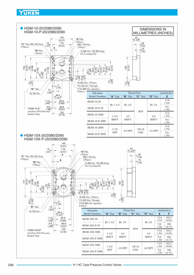
H / HC Type Pressure Control Valves246
DIMENSIONS INMILLIMETRES (INCHES)
Sub-plate
Model Numbers
HGM-10X-20
Rc 1-1/2
13.6 (.54)
"A" Thd. E F
102.5 (4.04)
9.6 (.38)
106(4.17)
13.6 (.54)
102.5 (4.04)
9.6 (.38)
106(4.17)
13.6 (.54)
102.5 (4.04)
9.6 (.38)
106(4.17)
"B" Thd. "C" Thd.
mm(Inches)Thead Size
"D" Thd.
HGM-10X-P-20
HGM-10X-2080
HGM-10X-P-2080
HGM-10X-2090
HGM-10X-P-2090
1-1/2
BSP.F
1-1/2
NPT
Rc 1/4
1/4
BSP.F
1/4 NPT
M10
3/8-16
UNC
Rc 1/4
1/4
BSP.F
1/4 NPT
Sub-plate
Model Numbers
HGM-10-20
Rc 1-1/4
13.6 (.54)
"A" Thd. E
9.6 (.38)
13.6 (.54)
9.6 (.38)
13.6 (.54)
9.6 (.38)
"B" Thd.
mm(Inches)Thread Size
"C" Thd. "D" Thd.
HGM-10-P-20
HGM-10-2080
HGM-10-P-2080
HGM-10-2090
HGM-10-P-2090
1-1/4
BSP.F
1-1/4
NPT
Rc 1/4
1/4
BSP.F
1/4 NPT
M10
3/8-16
UNC
Rc 1/4
1/4
BSP.F
1/4 NPT
4 (.16)
116
(4.57)12
(.47)
43
(1.6
9)
126
(4.9
6)
150
(5.9
1)
12
(.47)
11.6 (.46)
16.7
(.66)
24.6
(.97)
42.1
(1.6
6)
140
(5.51)45
(1.77)20
(.79)28(1.10) Dia.
2 Places
7(.28) Dia. 10(.39) Deep
For Locating Pin
"A"Thd.
2 Places
"B"Thd.
2 Places
5(.20) Dia. 2 Places
140
(5.51)
116
(4.57)
12
(.47)
F
104
(4.0
9)
177
(6.9
7)
126
(4.9
6)
11.6
(.46)
16.7
(.66)
50
(1.97)
20(.79)
"A"Thd.
2 Places
7(.28) Dia. 10(.39) Deep
For Locating Pin
E
96
(3.7
8)
"D" Thd.
4(.16) Dia.
"HGM-10-P"
Auxiliary Pilot Pressure
Models Only
9.6 (.38)
15
(.59)48.4
(1.91)
92.9 (3.66)
96.8 (3.81)
120 (4.72)
11(.43) Dia. Through
17.5(.69) Dia. Spotface 4 Places
E
28(1.10) Dia.
2 Places
135
(5.3
1)
7.5
(.30)
59.5
(2
.34)
62.7
(2.4
7)
67.5
(2
.66)
84.1
(3
.31)
21
(.83)
43
(1.6
9)
25.5
(1.0
0)
"D" Thd.
4(.16) Dia.
"HGM-10X-P"
Auxiliary Pilot Pressure
Models Only
9.6
(.38)
15
(.59)48.4
(1.91)92.9
(3.66)
96.8 (3.81)
120
(4.72)
24.6
(.97)
42.1
(1
.66)
59.5
(2.3
4)
62.7
(2.4
7)
67.5
(2.6
6)
84.1
(3.3
1)
21
(.83)
167
(6.5
7)
5
(.20)
HGM-10-20/2080/2090 HGM-10-P-20/2080/2090
HGM-10X-20/2080/2090 HGM-10X-P-20/2080/2090
"C" Thd. 20(.79) Deep
6 Places
"B"Thd.
2 Places
"C" Thd. 20(.79) Deep
6 Places
19
(.75)
5(.20) Dia. 2 Places
11(.43) Dia. Through
17.5(.69) Dia. Spotface 4 Places
19(.75)
22
(.87)
30
(1.1
8)
4 (.16)
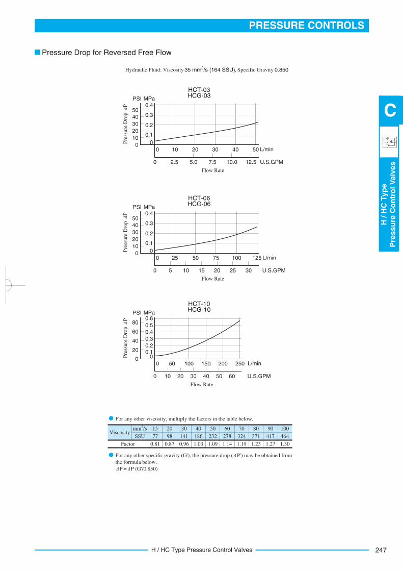
247
PRESSURE CONTROLS
H/H
CTyp
eP
ressu
reC
on
tro
lV
alv
es
C
H / HC Type Pressure Control Valves
15 20 30 40 50 60 70 80 90 100
77 98 141 186 232 278 324 371 417 464
0.81 0.87 0.96 1.03 1.09 1.14 1.19 1.23 1.27 1.30
2 mm /s
SSU
Factor
Viscosity
HCT-03 HCG-03
Pre
ssure
Dro
p P 0.4
50
MPaPSI
0.3
0.2
0.1
0
40
30
20
10
050 L/min403020100
12.5 U.S.GPM10.05.0 7.52.50
Flow Rate
HCT-06 HCG-06
Pre
ssure
Dro
p P 0.4
50
MPaPSI
0.3
0.2
0.1
0
40
30
20
10
0125 L/min1007550250
U.S.GPM2010 1550
Flow Rate
25 30
HCT-10 HCG-10
Pre
ssure
Dro
p P 0.6
80
MPaPSI
0.5
0.3
0.10
60
40
20
0L/min200150100500
U.S.GPM4020 30100
Flow Rate
50 60
0.4
0.2
250
Pressure Drop for Reversed Free Flow
Hydraulic Fluid: Viscosity 2 35 mm /s (164 SSU), Specific Gravity 0.850
For any other viscosity, multiply the factors in the table below.
For any other specific gravity (G'), the pressure drop ( P') may be obtained from
the formula below.
P'= P (G'/0.850)
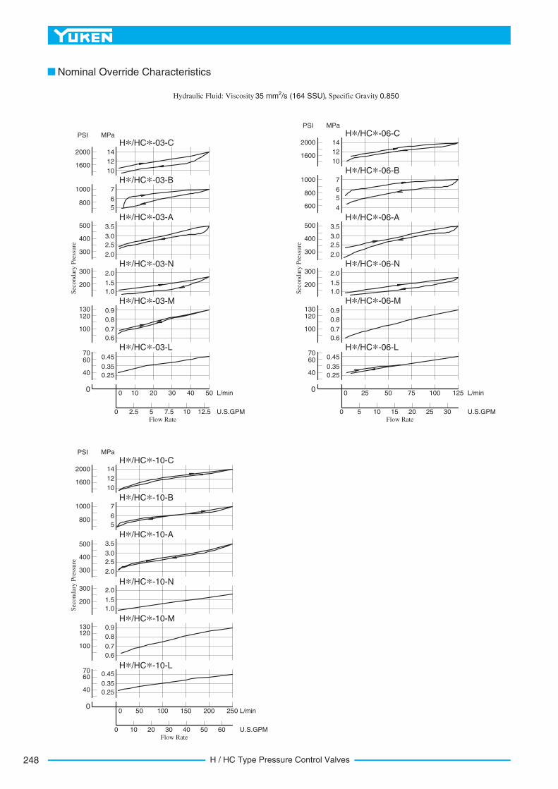
H / HC Type Pressure Control Valves248
Nominal Override Characteristics
Hydraulic Fluid: Viscosity 2 35 mm /s (164 SSU), Specific Gravity 0.850
H*/HC*-06-C
H*/HC*-06-B
H*/HC*-06-A
H*/HC*-06-N
H*/HC*-06-M
H*/HC*-06-L
2000
1600
1000
800
500
400
300
300
200
120130
100
6070
0
40
14
12
10
7
6
5
600 4
3.5
3.0
2.5
2.0
2.0
1.5
1.0
0.8
0.7
0.6
0 25 50 75 100 125
0 5 10 15 20 25 30
L/min
U.S.GPM
0.45
0.35
0.25
0.9
MPaPSI
Sec
on
dar
y P
ress
ure
Flow Rate
H*/HC*-03-C
H*/HC*-03-B
H*/HC*-03-A
H*/HC*-03-N
H*/HC*-03-M
H*/HC*-03-L
2000
1600
1000
800
500
400
300
300
200
120130
100
6070
0
40
14
12
10
7
6
5
3.5
3.0
2.5
2.0
2.0
1.5
1.0
0.8
0.7
0.6
0 10 20 30 40 50
0 2.5 5 7.5 10 12.5
L/min
U.S.GPM
0.45
0.35
0.25
0.9
MPaPSI
Sec
on
dar
y P
ress
ure
Flow Rate
H*/HC*-10-C
H*/HC*-10-B
H*/HC*-10-A
H*/HC*-10-N
H*/HC*-10-M
H*/HC*-10-L
2000
1600
1000
800
500
400
300
300
200
120130
100
6070
0
40
14
12
10
7
6
5
3.5
3.0
2.5
2.0
2.0
1.5
1.0
0.8
0.7
0.6
0 50 100 150 200 250
0 10 20 30 40 50 60
L/min
U.S.GPM
0.45
0.35
0.25
0.9
MPaPSI
Sec
on
dar
y P
ress
ure
Flow Rate
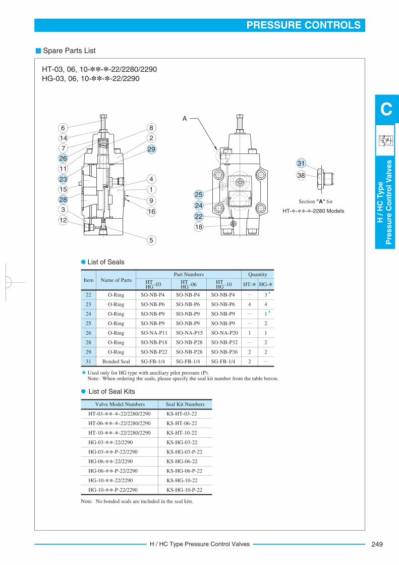
249
PRESSURE CONTROLS
H/H
CTyp
eP
ressu
reC
on
tro
lV
alv
es
C
H / HC Type Pressure Control Valves
Spare Parts List
O-Ring22
Item
3
O-Ring23 44
O-Ring24
O-Ring25 2
O-Ring26 11
O-Ring28 2
O-Ring29 22
Bonded Seal31 2
HT HG -03 HT
HG -06 HT HG -10 HT-* HG-*
QuantityPart NumbersName of Parts
1
Valve Model Numbers
HT-03-**-*-22/2280/2290
HT-06-**-*-22/2280/2290
HT-10-**-*-22/2280/2290
HG-03-**-22/2290
HG-03-**-P-22/2290
HG-06-**-22/2290
HG-06-**-P-22/2290
HG-10-**-22/2290
HG-10-**-P-22/2290
Seal Kit Numbers
KS-HT-03-22
KS-HT-06-22
KS-HT-10-22
KS-HG-03-22
KS-HG-03-P-22
KS-HG-06-22
KS-HG-06-P-22
KS-HG-10-22
KS-HG-10-P-22
SO-NB-P4
SO-NB-P6
SO-NB-P9
SO-NB-P9
SO-NA-P11
SO-NB-P18
SO-NB-P22
SG-FB-1/4
SO-NB-P4
SO-NB-P6
SO-NB-P9
SO-NB-P9
SO-NA-P15
SO-NB-P28
SO-NB-P28
SG-FB-1/4
SO-NB-P4
SO-NB-P6
SO-NB-P9
SO-NB-P9
SO-NA-P20
SO-NB-P32
SO-NB-P36
SG-FB-1/4
HT-03, 06, 10-**-*-22/2280/2290
HG-03, 06, 10-**-*-22/2290
List of Seals
Used only for HG type with auxiliary pilot pressure (P). Note: When ordering the seals, please specify the seal kit number from the table berow.
List of Seal Kits
Note: No bonded seals are included in the seal kits.
6
14
7
11
15
3
12
8
2
4
1
9
16
5
18
A
38
HT-*-**-*-2280 Models
Section "A" for
26
23
28
29
25
24
22
31
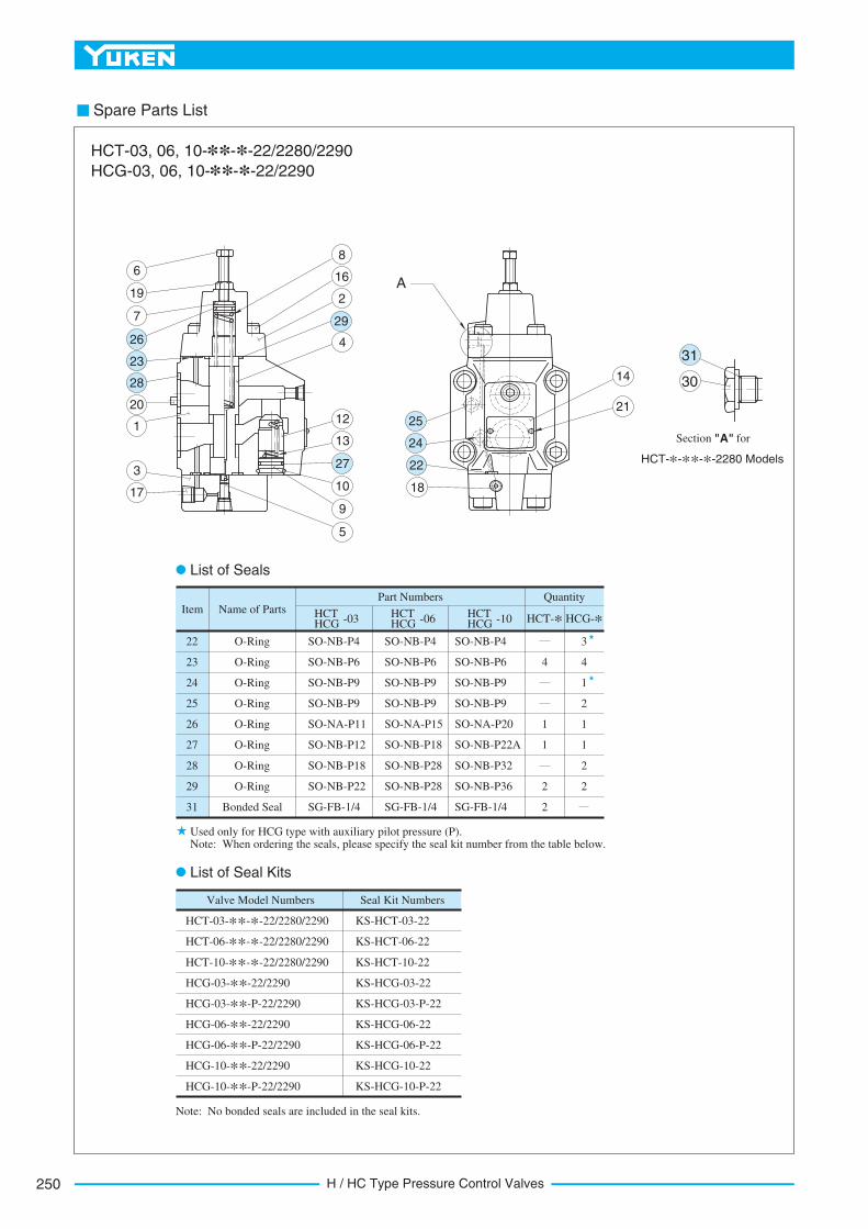
H / HC Type Pressure Control Valves250
Spare Parts List
O-Ring22
Item
O-Ring23 4
O-Ring24
O-Ring25
O-Ring26 1
O-Ring27 1
O-Ring28
Bonded Seal
29
2
HCT HCG -03 HCT-* HCG-*
QuantityPart NumbersName of Parts
Valve Model Numbers Seal Kit Numbers
2
31
O-Ring 2
2
1
1
2
1
4
3
HCT-03-**-*-22/2280/2290
HCT-06-**-*-22/2280/2290
HCT-10-**-*-22/2280/2290
HCG-03-**-22/2290
HCG-03-**-P-22/2290
HCG-06-**-22/2290
HCG-06-**-P-22/2290
HCG-10-**-22/2290
HCG-10-**-P-22/2290
KS-HCT-03-22
KS-HCT-06-22
KS-HCT-10-22
KS-HCG-03-22
KS-HCG-03-P-22
KS-HCG-06-22
KS-HCG-06-P-22
KS-HCG-10-22
KS-HCG-10-P-22
HCT HCG -06 HCT
HCG -10
SO-NB-P4
SO-NB-P6
SO-NB-P9
SO-NB-P9
SO-NA-P11
SO-NB-P12
SO-NB-P18
SG-FB-1/4
SO-NB-P22
SO-NB-P4
SO-NB-P6
SO-NB-P9
SO-NB-P9
SO-NA-P15
SO-NB-P18
SO-NB-P28
SG-FB-1/4
SO-NB-P28
SO-NB-P4
SO-NB-P6
SO-NB-P9
SO-NB-P9
SO-NA-P20
SO-NB-P22A
SO-NB-P32
SG-FB-1/4
SO-NB-P36
HCT-03, 06, 10-**-*-22/2280/2290
HCG-03, 06, 10-**-*-22/2290
List of Seals
Used only for HCG type with auxiliary pilot pressure (P). Note: When ordering the seals, please specify the seal kit number from the table below.
List of Seal Kits
Note: No bonded seals are included in the seal kits.
30
HCT-*-**-*-2280 Models
Section "A" for
18
21
14
A6
19
7
20
1
3
17
12
13
10
9
5
8
16
2
431
25
24
22
26
23
28
27
29
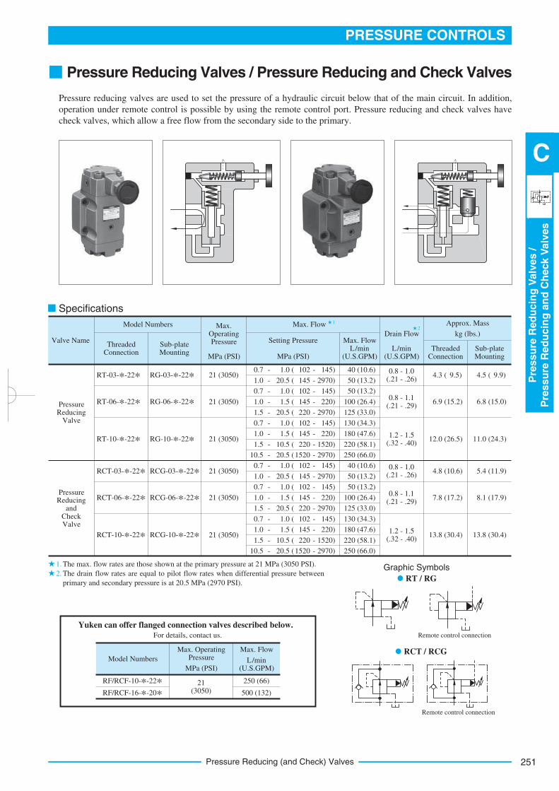
251
PRESSURE CONTROLS
Pre
ssu
reR
ed
ucin
gV
alv
es
/P
ressu
reR
ed
ucin
gan
dC
heck
Valv
es
C
Pressure Reducing (and Check) Valves
Pressure Reducing Valves / Pressure Reducing and Check Valves
Pressure reducing valves are used to set the pressure of a hydraulic circuit below that of the main circuit. In addition,
operation under remote control is possible by using the remote control port. Pressure reducing and check valves have
check valves, which allow a free flow from the secondary side to the primary.
1
2
1.
2.
Specifications
Valve Name
RT-03-*-22*
Pressure Reducing
Valve
Pressure Reducing
and Check Valve
RCT-03-*-22*
Model Numbers
Threaded Connection
Sub-plate Mounting
RT-06-*-22*
RT-10-*-22*
RCT-06-*-22*
RCT-10-*-22*
RG-03-*-22*
RCG-03-*-22*
RG-06-*-22*
RG-10-*-22*
RCG-06-*-22*
RCG-10-*-22*
Max. Flow
Setting Pressure
MPa (PSI)
Max. FlowL/min
(U.S.GPM)L/min
(U.S.GPM)
Drain Flow
Threaded Connection
Sub-plate Mounting
Approx. Mass
kg (lbs.)
0.7 - 1.0 ( 102 - 145)
1.0 - 20.5 ( 145 - 2970)
0.7 - 1.0 ( 102 - 145)
1.0 - 1.5 ( 145 - 220)
1.5 - 20.5 ( 220 - 2970)
0.7 - 1.0 ( 102 - 145)
1.0 - 1.5 ( 145 - 220)
1.5 - 10.5 ( 220 - 1520)
10.5 - 20.5 ( 1520 - 2970)
0.7 - 1.0 ( 102 - 145)
1.0 - 20.5 ( 145 - 2970)
0.7 - 1.0 ( 102 - 145)
1.0 - 1.5 ( 145 - 220)
1.5 - 20.5 ( 220 - 2970)
0.7 - 1.0 ( 102 - 145)
1.0 - 1.5 ( 145 - 220)
1.5 - 10.5 ( 220 - 1520)
10.5 - 20.5 ( 1520 - 2970)
0.8 - 1.0 (.21 - .26)
0.8 - 1.1 (.21 - .29)
1.2 - 1.5 (.32 - .40)
0.8 - 1.0 (.21 - .26)
0.8 - 1.1 (.21 - .29)
1.2 - 1.5 (.32 - .40)
4.3 ( 9.5)
6.9 ( 15.2)
12.0 ( 26.5)
4.5 ( 9.9)
6.8 ( 15.0)
11.0 ( 24.3)
4.8 ( 10.6)
7.8 ( 17.2)
13.8 ( 30.4)
5.4 ( 11.9)
8.1 (17.9)
13.8 (30.4)
Max. Operating Pressure
MPa (PSI)
Max. Flow
L/min (U.S.GPM)
Model Numbers
RF/RCF-10-*-22*RF/RCF-16-*-20*
21 (3050)
250 (66)
500 (132)
21 (3050)
Max. Operating Pressure
MPa (PSI)
21 (3050)
21 (3050)
21 (3050)
21 (3050)
21 (3050)
40 (10.6)
50 (13.2)
50 (13.2)
100 (26.4)
125 (33.0)
130 (34.3)
180 (47.6)
220 (58.1)
250 (66.0)
40 (10.6)
50 (13.2)
50 (13.2)
100 (26.4)
125 (33.0)
130 (34.3)
180 (47.6)
220 (58.1)
250 (66.0)
Graphic Symbols
RT / RG
Remote control connection
RCT / RCG
Remote control connection
Yuken can offer flanged connection valves described below.
For details, contact us.
The max. flow rates are those shown at the primary pressure at 21 MPa (3050 PSI).
The drain flow rates are equal to pilot flow rates when differential pressure between
primary and secondary pressure is at 20.5 MPa (2970 PSI).
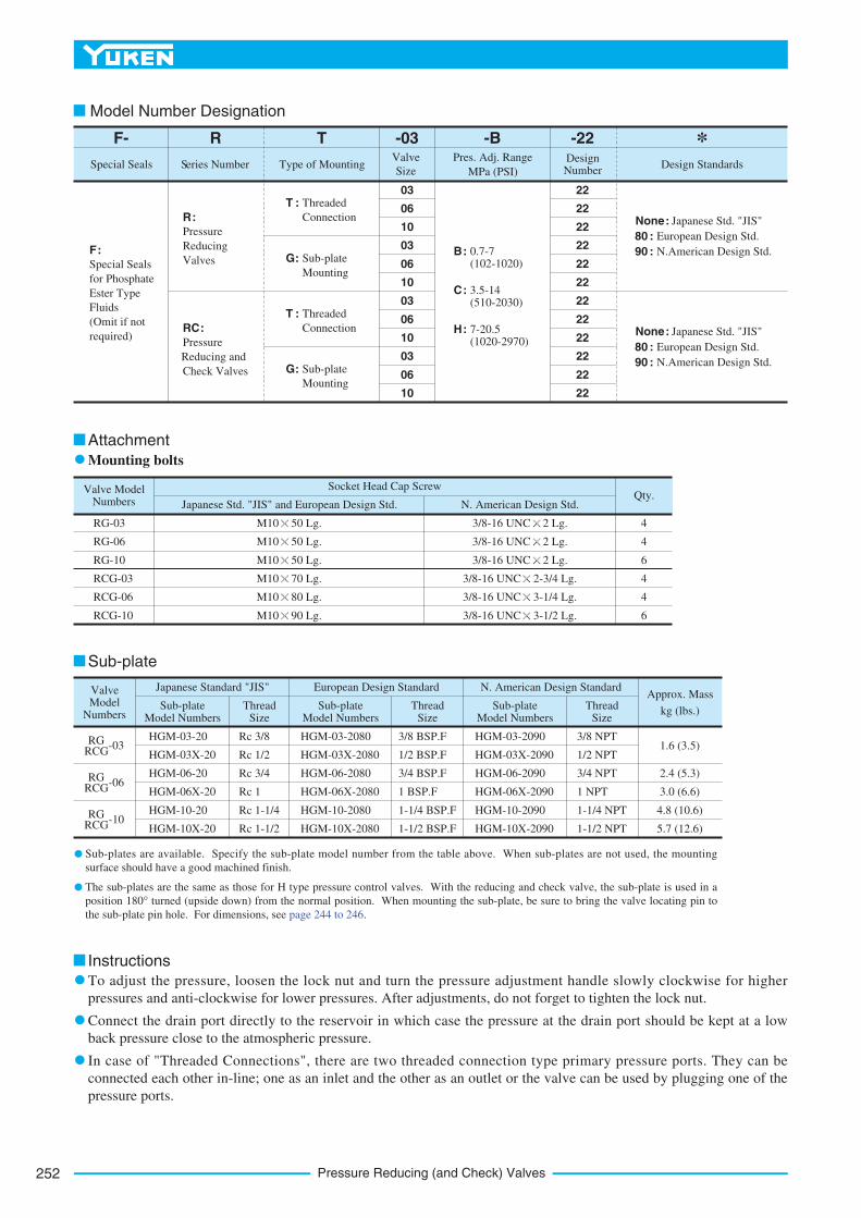
Pressure Reducing (and Check) Valves252
1.6 (3.5)
2.4 (5.3)
3.0 (6.6)
4.8 (10.6)
5.7 (12.6)
Valve Model Numbers
RG-03
RG-06
RG-10
RCG-03
RCG-06
RCG-10
Socket Head Cap Screw
Japanese Std. "JIS" and European Design Std. N. American Design Std.Qty.
M10 50 Lg.
M10 50 Lg.
M10 50 Lg.
M10 70 Lg.
M10 80 Lg.
M10 90 Lg.
3/8-16 UNC 2 Lg.
3/8-16 UNC 2 Lg.
3/8-16 UNC 2 Lg.
3/8-16 UNC 2-3/4 Lg.
3/8-16 UNC 3-1/4 Lg.
3/8-16 UNC 3-1/2 Lg.
4
4
6
4
4
6
Valve Model
Numbers
-03RG RCG
-06RG RCG
-10RG RCG
Japanese Standard "JIS"
Sub-plate Model Numbers
Thread Size
European Design Standard
Sub-plate Model Numbers
Thread Size
N. American Design Standard
Sub-plate Model Numbers
Thread Size
Approx. Mass
kg (lbs.)
HGM-03-20
HGM-03X-20
HGM-06-20
HGM-06X-20
HGM-10-20
HGM-10X-20
Rc 3/8
Rc 1/2
Rc 3/4
Rc 1
Rc 1-1/4
Rc 1-1/2
HGM-03-2080
HGM-03X-2080
HGM-06-2080
HGM-06X-2080
HGM-10-2080
HGM-10X-2080
3/8 BSP.F
1/2 BSP.F
3/4 BSP.F
1 BSP.F
1-1/4 BSP.F
1-1/2 BSP.F
HGM-03-2090
HGM-03X-2090
HGM-06-2090
HGM-06X-2090
HGM-10-2090
HGM-10X-2090
3/8 NPT
1/2 NPT
3/4 NPT
1 NPT
1-1/4 NPT
1-1/2 NPT
Attachment
Mounting bolts
Sub-plate
Instructions
Model Number Designation
Special Seals
for Phosphate
Ester Type
Fluids
(Omit if not
required)
F:
03
06
10
03
06
10
03
06
10
03
06
10
C: 3.5-14 (510-2030)
H: 7-20.5 (1020-2970)
B: 0.7-7 (102-1020)
Pressure
Reducing
Valves
R:
Pressure
Reducing and
Check Valves
RC:
Threaded
Connection
T :
Sub-plate
Mounting
G:
Threaded
Connection
T :
Sub-plate
Mounting
G:
22
22
22
22
22
22
22
22
22
22
22
22
F- R
Special Seals Series Number
T
Type of Mounting
-22Design Number
*Design Standards
-03 -BPres. Adj. Range
MPa (PSI)
Valve
Size
None: Japanese Std. "JIS"
80 : European Design Std.
90 : N.American Design Std.
None: Japanese Std. "JIS"
80 : European Design Std.
90 : N.American Design Std.
Sub-plates are available. Specify the sub-plate model number from the table above. When sub-plates are not used, the mounting
surface should have a good machined finish.
The sub-plates are the same as those for H type pressure control valves. With the reducing and check valve, the sub-plate is used in a
position 180° turned (upside down) from the normal position. When mounting the sub-plate, be sure to bring the valve locating pin to
the sub-plate pin hole. For dimensions, see page 244 to 246.
To adjust the pressure, loosen the lock nut and turn the pressure adjustment handle slowly clockwise for higher
pressures and anti-clockwise for lower pressures. After adjustments, do not forget to tighten the lock nut.
Connect the drain port directly to the reservoir in which case the pressure at the drain port should be kept at a low
back pressure close to the atmospheric pressure.
In case of "Threaded Connections", there are two threaded connection type primary pressure ports. They can be
connected each other in-line; one as an inlet and the other as an outlet or the valve can be used by plugging one of the
pressure ports.
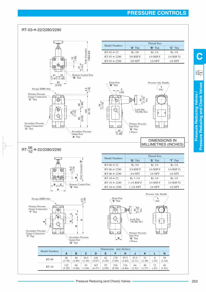
253
PRESSURE CONTROLS
Pre
ssu
reR
ed
ucin
gV
alv
es
/P
ressu
reR
ed
ucin
gan
dC
heck
Valv
es
C
Pressure Reducing (and Check) Valves
DIMENSIONS INMILLIMETRES (INCHES)
Model Numbers
RT-03-*-22
RT-03-*-2280
RT-03-*-2290
Rc 3/8
3/8 BSP.F
3/8 NPT
"A" Thd. "B" Thd. "C" Thd.
Rc 1/4
1/4 BSP.F
1/4 NPT
Rc 1/4
1/4 BSP.Tr
1/4 NPT
Thread Size
Model Numbers
RT-06-*-22
RT-06-*-2280
RT-06-*-2290
RT-10-*-22
RT-10-*-2280
RT-10-*-2290
Rc 3/4
3/4 BSP.F
3/4 NPT
Rc 1-1/4
1-1/4 BSP.F
1-1/4 NPT
"Q" Thd. "S" Thd. "T" Thd.
Rc 1/4
1/4 BSP.F
1/4 NPT
Rc 1/4
1/4 BSP.F
1/4 NPT
Rc 1/4
1/4 BSP.Tr
1/4 NPT
Rc 1/4
1/4 BSP.Tr
1/4 NPT
Thread Size
Model NumbersA
Dimensions mm (Inches)
B C D E F H J K L N
RT-06
RT-10
96 (3.78)
132 (5.20)
48 (1.89)
66 (2.60)
36.5 (1.44)
43 (1.69)
149 (5.87)
167 (6.57)
42 (1.65)
52 (2.05)
179 (7.05)
216 (8.50)
97.5 (3.84)
124 (4.88)
53.5 (2.11)
64 (2.52)
33 (1.30)
40 (1.57)
9 (.35)
12 (.47)
39 (1.54)
46 (1.81)
48
(1.8
9)
Lock Nut 14(.55) Hex.
Pressure Adj. Handle
INC.5(.20)
33
(1.30)
28
(1.1
0)
148(5
.83)
Full
y E
xte
nded
44
(1.7
3)
10
(.39)
Secondary Pressure Gauge Connection "C" Thd.
Remote Control Port "B" Thd.
41
(1.6
1)
41
(1.61)
Primary Pressure Gauge Connection "C" Thd.
85
(3.3
5)
155
(6.1
0)
4.5
(.18)
Secondary Pressure Outlet Port "A" Thd.
32
(1.26)
Primary Pressure Inlet Port "A" Thd. 2 Places
Design 2280 Only
82(3.23)
Drain Port "B" Thd.
44
(1.7
3)
Dia
.
Full
y E
xte
nded
"D
"
Remote Control Port "S" Thd.
18.5
(.73)
B
A
B C
Secondary Pressure Gauge Connection "T" Thd.
Primary Pressure Gauge Connection
"T" Thd.
4.5
(.18)Design 2280 Only
Secondary Pressure
Outlet Port "Q" Thd.
F
JH
LK
Drain Port "S" Thd.
44
(1.7
3)
Dia
.
N
Lock Nut 14(.55) Hex.
Pressure Adj. Handle
INC.
Primary Pressure Inlet Port "Q" Thd. 2 Places
E
RT-03-*-22/2280/2290
06 10
RT- -*-22/2280/2290
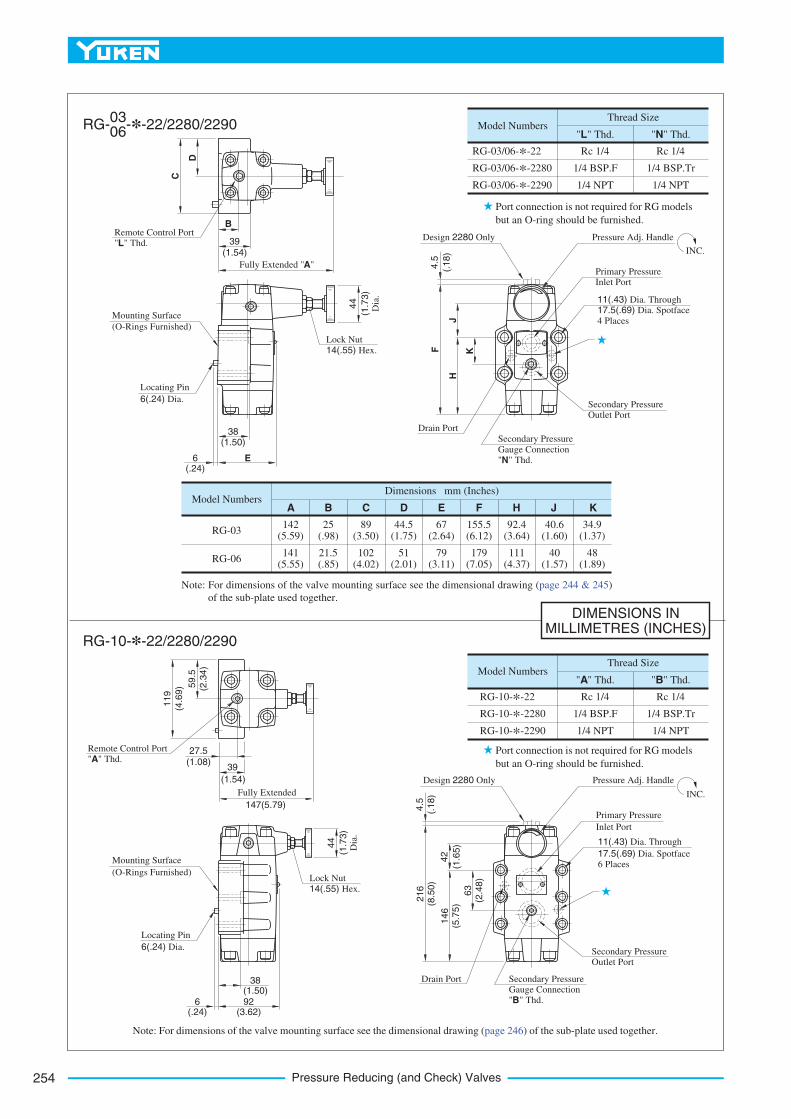
Pressure Reducing (and Check) Valves254
DIMENSIONS INMILLIMETRES (INCHES)
03 06
RG- -*-22/2280/2290
RG-10-*-22/2280/2290
Model Numbers
RG-03/06-*-22
RG-03/06-*-2280
RG-03/06-*-2290
Rc 1/4
1/4 BSP.F
1/4 NPT
"L" Thd.
Rc 1/4
1/4 BSP.Tr
1/4 NPT
Thread Size
Model NumbersA
Dimensions mm (Inches)
B C D E F J KH
RG-03
RG-06
142 (5.59)
141 (5.55)
25 (.98)
21.5 (.85)
89 (3.50)
102 (4.02)
44.5 (1.75)
51 (2.01)
67 (2.64)
79 (3.11)
155.5 (6.12)
179 (7.05)
40.6 (1.60)
40 (1.57)
34.9 (1.37)
48 (1.89)
92.4 (3.64)
111 (4.37)
Model Numbers
RG-10-*-22
RG-10-*-2280
RG-10-*-2290
Rc 1/4
1/4 BSP.F
1/4 NPT
"A" Thd. "B" Thd.
Rc 1/4
1/4 BSP.Tr
1/4 NPT
Thread Size
"N" Thd.
216
(8.5
0)
Lock Nut
14(.55) Hex.
Pressure Adj. Handle
INC.
6(.24)
Remote Control Port "L" Thd.
4.5
(.18)
Secondary Pressure Outlet Port
Primary Pressure Inlet Port
Design 2280 Only
44
(1.7
3)
Dia
.
59.5
(2.3
4)
4.5
(.18)
D
C
Fully Extended "A"
B
39(1.54)
E
Mounting Surface
(O-Rings Furnished)
Locating Pin
6(.24) Dia.
Drain Port
Secondary Pressure
Gauge Connection "N" Thd.
F
J
K
H
11(.43) Dia. Through 17.5(.69) Dia. Spotface
4 Places
119
(4.6
9)
Fully Extended
27.5(1.08)
39
(1.54)
147(5.79)
Remote Control Port "A" Thd.
6(.24)
92(3.62)
44
(1.7
3)
Dia
.
Lock Nut
14(.55) Hex.
Mounting Surface
(O-Rings Furnished)
Locating Pin
6(.24) Dia.
146
(5.7
5)
63
(2.4
8)
42
(1.6
5)
Pressure Adj. Handle
INC.
Secondary Pressure Outlet Port
Primary Pressure
Inlet Port
Design 2280 Only
Drain Port Secondary Pressure Gauge Connection "B" Thd.
11(.43) Dia. Through
17.5(.69) Dia. Spotface 6 Places
Port connection is not required for RG models
but an O-ring should be furnished.
Port connection is not required for RG models
but an O-ring should be furnished.
38(1.50)
38(1.50)
Note: For dimensions of the valve mounting surface see the dimensional drawing (page 244 & 245)
of the sub-plate used together.
Note: For dimensions of the valve mounting surface see the dimensional drawing (page 246) of the sub-plate used together.
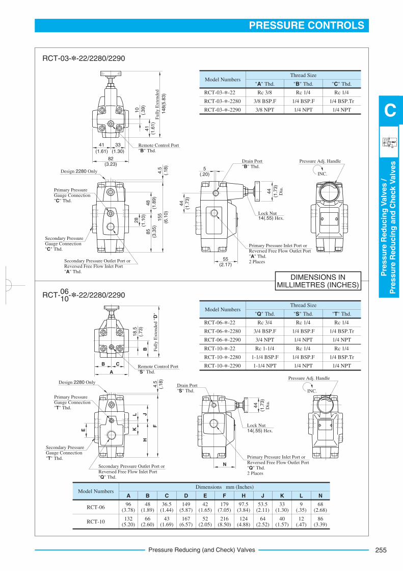
255
PRESSURE CONTROLS
Pre
ssu
reR
ed
ucin
gV
alv
es
/P
ressu
reR
ed
ucin
gan
dC
heck
Valv
es
C
Pressure Reducing (and Check) Valves
DIMENSIONS INMILLIMETRES (INCHES)
Model Numbers
RCT-03-*-22
RCT-03-*-2280
RCT-03-*-2290
Rc 3/8
3/8 BSP.F
3/8 NPT
"A" Thd. "B" Thd. "C" Thd.
Rc 1/4
1/4 BSP.F
1/4 NPT
Rc 1/4
1/4 BSP.Tr
1/4 NPT
Thread Size
48
(1.8
9)
Lock Nut 14(.55) Hex.
Pressure Adj. Handle
INC.5
(.20)
33
(1.30)
28
(1.1
0)
148(5
.83)
Full
y E
xte
nded
44
(1.7
3)
10
(.39)
Secondary Pressure Gauge Connection "C" Thd.
Remote Control Port "B" Thd.
41
(1.6
1)
41
(1.61)
Primary Pressure Gauge Connection "C" Thd.
85
(3.3
5)
155
(6.1
0)
4.5
(.18)
Secondary Pressure Outlet Port or Reversed Free Flow Inlet Port "A" Thd.
55(2.17)
Primary Pressure Inlet Port or Reversed Free Flow Outlet Port "A" Thd. 2 Places
Design 2280 Only
82(3.23)
Drain Port "B" Thd.
44
(1.7
3)
Dia
.
RCT-03-*-22/2280/2290
Model Numbers
RCT-06-*-22
RCT-06-*-2280
RCT-06-*-2290
RCT-10-*-22
RCT-10-*-2280
RCT-10-*-2290
Rc 3/4
3/4 BSP.F
3/4 NPT
Rc 1-1/4
1-1/4 BSP.F
1-1/4 NPT
"Q" Thd. "S" Thd. "T" Thd.
Rc 1/4
1/4 BSP.F
1/4 NPT
Rc 1/4
1/4 BSP.F
1/4 NPT
Rc 1/4
1/4 BSP.Tr
1/4 NPT
Rc 1/4
1/4 BSP.Tr
1/4 NPT
Thread Size
Model NumbersA
Dimensions mm (Inches)
B C D E F H J K L N
RCT-06
RCT-10
96 (3.78)
132 (5.20)
48 (1.89)
66 (2.60)
36.5 (1.44)
43 (1.69)
149 (5.87)
167 (6.57)
42 (1.65)
52 (2.05)
179 (7.05)
216 (8.50)
97.5 (3.84)
124 (4.88)
53.5 (2.11)
64 (2.52)
33 (1.30)
40 (1.57)
9 (.35)
12 (.47)
68 (2.68)
86 (3.39)
Full
y E
xte
nded
"D
"
Remote Control Port "S" Thd.
18.5
(.73)
B
A
B C
Secondary Pressure Gauge Connection
"T" Thd.
Primary Pressure Gauge Connection "T" Thd.
4.5
(.18)
Design 2280 Only
F
JH
LK
Drain Port "S" Thd.
44
(1.7
3)
Dia
.
Lock Nut 14(.55) Hex.
Pressure Adj. Handle
INC.
E
Secondary Pressure Outlet Port or
Reversed Free Flow Inlet Port "Q" Thd.
N
Primary Pressure Inlet Port or
Reversed Free Flow Outlet Port "Q" Thd. 2 Places
06 10
RCT- -*-22/2280/2290
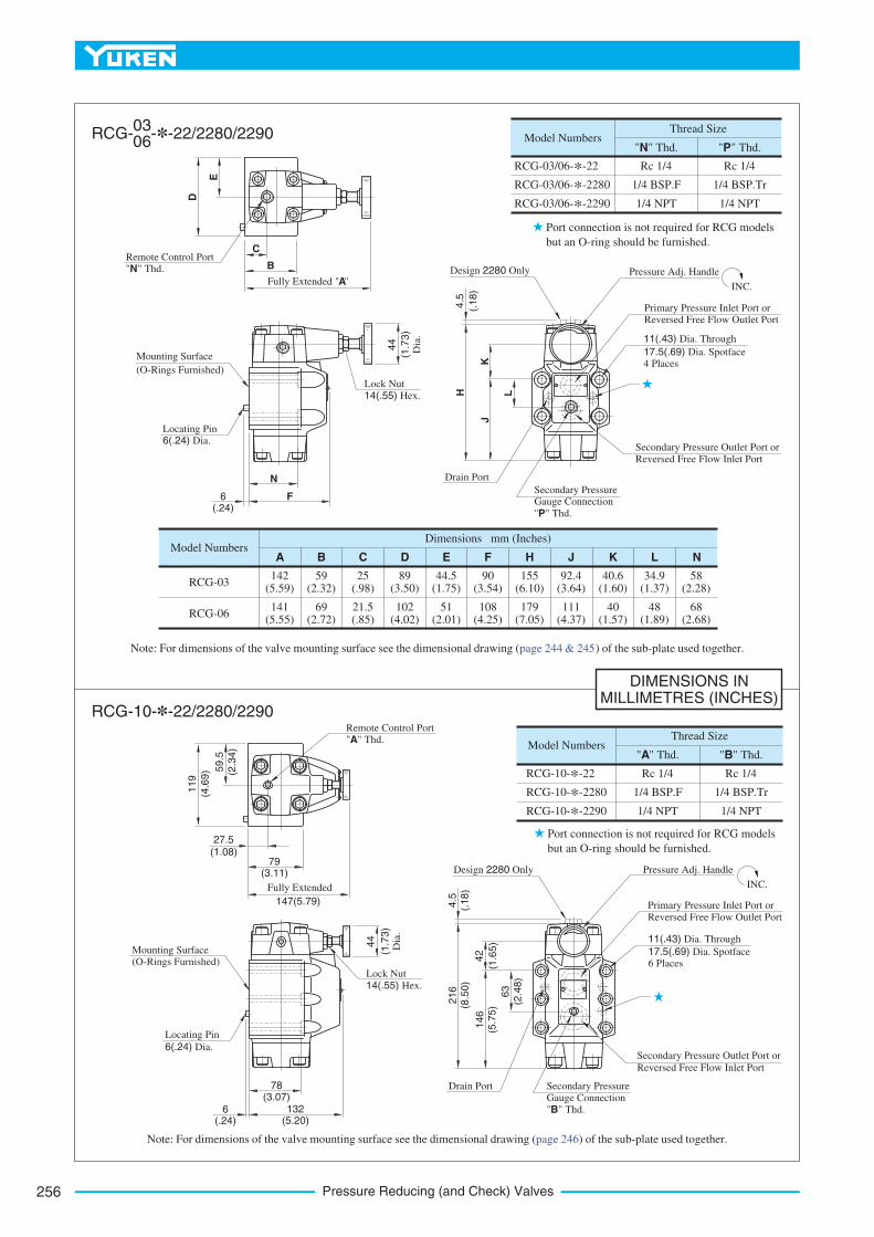
Pressure Reducing (and Check) Valves256
DIMENSIONS INMILLIMETRES (INCHES)
Model Numbers
RCG-03/06-*-22
RCG-03/06-*-2280
RCG-03/06-*-2290
Rc 1/4
1/4 BSP.F
1/4 NPT
"N" Thd.
Rc 1/4
1/4 BSP.Tr
1/4 NPT
Thread Size
Model NumbersA
Dimensions mm (Inches)
B C D E F H J N
RCG-03
RCG-06
142 (5.59)
141 (5.55)
25 (.98)
21.5 (.85)
89 (3.50)
102 (4.02)
44.5 (1.75)
51 (2.01)
155 (6.10)
179 (7.05)
40.6 (1.60)
40 (1.57)
58(2.28)
68(2.68)
Model Numbers
RCG-10-*-22
RCG-10-*-2280
RCG-10-*-2290
Rc 1/4
1/4 BSP.F
1/4 NPT
"A" Thd. "B" Thd.
Rc 1/4
1/4 BSP.Tr
1/4 NPT
Thread Size
"P" Thd.
K
92.4 (3.64)
111 (4.37)
59 (2.32)
69 (2.72)
90 (3.54)
108 (4.25)
Primary Pressure Inlet Port or Reversed Free Flow Outlet Port
Secondary Pressure Outlet Port or
Reversed Free Flow Inlet Port
Primary Pressure Inlet Port or
Reversed Free Flow Outlet Port
Secondary Pressure Outlet Port or
Reversed Free Flow Inlet Port
216
(8.5
0)
Lock Nut
14(.55) Hex.
Pressure Adj. Handle
INC.
6(.24)
Remote Control Port "N" Thd.
4.5
(.18)
Design 2280 Only
44
(1.7
3)
Dia
.
59.5
(2.3
4)
4.5
(.18)
E
D
Fully Extended "A"
C
F
Mounting Surface
(O-Rings Furnished)
Locating Pin 6(.24) Dia.
Drain Port
Secondary Pressure Gauge Connection
"P" Thd.
H
K
L
J
11(.43) Dia. Through
17.5(.69) Dia. Spotface 4 Places
119
(4.6
9)
Fully Extended
27.5(1.08)
79(3.11)
147(5.79)
Remote Control Port "A" Thd.
6(.24)
132(5.20)
44
(1.7
3)
Dia
.
Lock Nut
14(.55) Hex.
Mounting Surface (O-Rings Furnished)
Locating Pin
6(.24) Dia.
146
(5.7
5)
63
(2.4
8)
42
(1.6
5)
Pressure Adj. Handle
INC.
Design 2280 Only
Drain Port
"
Secondary Pressure
Gauge Connection
B" Thd.
11(.43) Dia. Through
17.5(.69) Dia. Spotface 6 Places
Port connection is not required for RCG models
but an O-ring should be furnished.
Port connection is not required for RCG models
but an O-ring should be furnished.
B
03 06
RCG- -*-22/2280/2290
RCG-10-*-22/2280/2290
L
34.9 (1.37)
48 (1.89)
Note: For dimensions of the valve mounting surface see the dimensional drawing (page 246) of the sub-plate used together.
N
78(3.07)
page 244 & 245
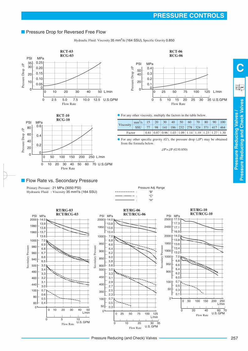
257
PRESSURE CONTROLS
Pre
ssu
reR
ed
ucin
gV
alv
es
/P
ressu
reR
ed
ucin
gan
dC
heck
Valv
es
C
Pressure Reducing (and Check) Valves
RCT-03 RCG-03
L/min
U.S.GPM
Pre
ssure
Dro
p P
MPaPSI
12.5
0.25
Flow Rate
0.20
0.15
0.10
0.050
3530
20
10
050403020100
10.07.55.02.50
RCT-06 RCG-06
L/min
U.S.GPM
Flow Rate
0 125100755025
0 5 10 15 20 25 30 35
Pre
ssure
Dro
p P
MPaPSI
00.1
0.2
0.3
0.4
0
20
4050
RCT-10 RCG-10
L/min
U.S.GPM
Flow Rate
0 25020015010050
0 10 20 30 40 50 60 70
Pre
ssure
Dro
p P
MPaPSI
0
0.2
0.4
0
20
40
60
0.680
Pressure Drop for Reversed Free Flow
Hydraulic Fluid: Viscosity 2 35 mm /s (164 SSU), Specific Gravity 0.850
Viscosity
2 mm /s
SSU
Factor
15
77
0.81
20
98
0.87
30
141
0.96
40
186
1.03
50
232
1.09
60
278
1.14
70
324
1.19
80
371
1.23
90
417
1.27
100
464
1.30
For any other viscosity, multiply the factors in the table below.
P'= P (G'/0.850)
For any other specific gravity (G'), the pressure drop ( P') may be obtained
from the formula below.
Primary Pressure : 21 MPa (3050 PSI)Hydrauric Fluid : Viscosity 35 mm2/s (164 SSU) "B"
"C"
"H"
Pressure Adj. Range
Flow Rate vs. Secondary Pressure
17.5
17.3
17.1
16.9
14.0
13.8
13.6
13.4
13.2
7.0
6.8
6.6
6.4
6.2
6.0
0.7
0.5
0.3
0.1
00
50 100 150 200 250L/min
U.S. GPM0 20 40 60 70
Flow Rate
100
50
900
1000
950
2000
1950
1900
2500
2450
PSI MPa
Sec
on
dar
y P
ress
ure
14.0
13.8
13.6
13.4
7.0
6.8
6.6
6.4
6.2
6.0
5.8
5.6
3.5
3.3
3.1
2.9
2.7
2.5
2.3
0.7
0.5
0.3
00
25 50 75 100 125L/min
0 10 20 30 35U.S. GPM
Flow Rate
100
50
PSI MPa
400
350
500
450
1000
950
900
850
800
2000
1950
Sec
on
dar
y P
ress
ure
14.0
13.9
13.8
13.7
13.6
7.0
6.9
6.8
6.7
6.6
6.5
3.5
3.4
3.3
3.2
3.1
3.0
0.7
0.6
0.5
0.4
00
10 20 30 40 50
100
80
60
PSI MPa
500
480
460
440
1980
2000
1960
1000
980
960
940
L/min
0 5 10U.S. GPM
Flow Rate
Sec
on
dar
y P
ress
ure
RT/RG-10 RCT/RCG-10
RT/RG-06 RCT/RCG-06
RT/RG-03 RCT/RCG-03
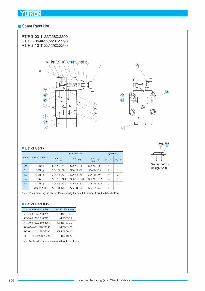
Pressure Reducing (and Check) Valves258
Spare Parts List
Item RT RG -03 RT
RG -06 RT RG -10 RT-* RG-*
QuantityPart Numbers
Name of Parts
Valve Model Numbers Seal Kit Numbers
SO-NB-P6
SO-NA-P9
SO-NB-P9
SO-NB-P18
SO-NB-P22
SG-FB-1/4
30
31
32
34
35
37
O-Ring
O-Ring
O-Ring
O-Ring
O-Ring
Bonded Seal
SO-NB-P6
SO-NA-P9
SO-NB-P9
SO-NB-P28
SO-NB-P28
SG-FB-1/4
SO-NB-P6
SO-NA-P9
SO-NB-P9
SO-NB-P32
SO-NB-P36
SG-FB-1/4
4
1
2
1
4
1
2
2
2
1
Note: When ordering the seals, please specify the seal kit number from the table below.
RT-03-*-22/2280/2290
RT-06-*-22/2280/2290
RT-10-*-22/2280/2290
RG-03-*-22/2280/2290
RG-06-*-22/2280/2290
RG-10-*-22/2280/2290
KS-RT-03-22
KS-RT-06-22
KS-RT-10-22
KS-RG-03-22
KS-RG-06-22
KS-RG-10-22
26
6 21 7 8 2 9 10 11 13
3
1
23
20
4
15
24
5
A
23
24
RT/RG-03-*-22/2280/2290 RT/RG-06-*-22/2280/2290 RT/RG-10-*-22/2280/2290
Section "A" for
Design 2280
List of Seals
List of Seal Kits
Note: No bonded seals are included in the seal kits.
37
31
35
34
3032
30
32
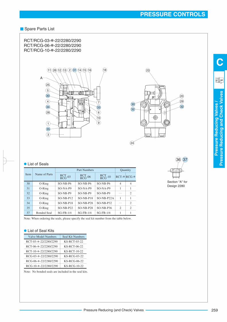
259
PRESSURE CONTROLS
Pre
ssu
reR
ed
ucin
gV
alv
es
/P
ressu
reR
ed
ucin
gan
dC
heck
Valv
es
C
Pressure Reducing (and Check) Valves
Spare Parts List
Item RCT RCG-03 RCT
RCG-06 RCT RCG-10 RCT-* RCG-*
QuantityPart Numbers
Name of Parts
Valve Model Numbers Seal Kit Numbers
SO-NB-P6
SO-NA-P9
SO-NB-P9
SO-NB-P12
SO-NB-P18
SO-NB-P22
SG-FB-1/4
30
31
32
33
34
35
37
O-Ring
O-Ring
O-Ring
O-Ring
O-Ring
O-Ring
Bonded Seal
SO-NB-P6
SO-NA-P9
SO-NB-P9
SO-NB-P18
SO-NB-P28
SO-NB-P28
SG-FB-1/4
SO-NB-P6
SO-NA-P9
SO-NB-P9
SO-NB-P22A
SO-NB-P32
SO-NB-P36
SG-FB-1/4
4
1
1
2
1
4
1
2
1
2
2
1
Note: When ordering the seals, please specify the seal kit number from the table below.
RCT-03-*-22/2280/2290
RCT-06-*-22/2280/2290
RCT-10-*-22/2280/2290
RCG-03-*-22/2280/2290
RCG-06-*-22/2280/2290
RCG-10-*-22/2280/2290
KS-RCT-03-22
KS-RCT-06-22
KS-RCT-10-22
KS-RCG-03-22
KS-RCG-06-22
KS-RCG-10-22
36
A
11 26 12 13 2 14 15 16 18
25
5
4
28
1
3
7
6
10
9
23
20
29
24
RCT/RCG-03-*-22/2280/2290 RCT/RCG-06-*-22/2280/2290 RCT/RCG-10-*-22/2280/2290
Section "A" for
Design 2280
List of Seals
List of Seal Kits
Note: No bonded seals are included in the seal kits.
37
31
30
34
35
33 3230
32
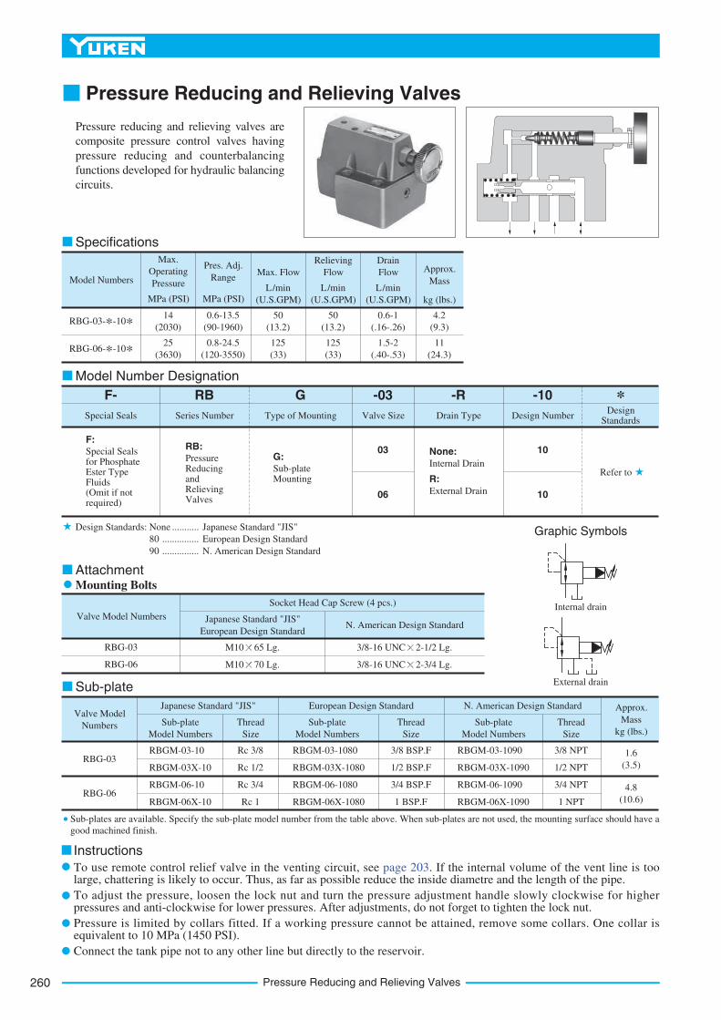
Pressure Reducing and Relieving Valves260
Instructions
To use remote control relief valve in the venting circuit, see page 203. If the internal volume of the vent line is too large, chattering is likely to occur. Thus, as far as possible reduce the inside diametre and the length of the pipe.
To adjust the pressure, loosen the lock nut and turn the pressure adjustment handle slowly clockwise for higher pressures and anti-clockwise for lower pressures. After adjustments, do not forget to tighten the lock nut.
Pressure is limited by collars fitted. If a working pressure cannot be attained, remove some collars. One collar is equivalent to 10 MPa (1450 PSI).
Connect the tank pipe not to any other line but directly to the reservoir.
Pressure Reducing and Relieving Valves
Pressure reducing and relieving valves are
composite pressure control valves having
pressure reducing and counterbalancing
functions developed for hydraulic balancing
circuits.
Model Numbers
Max.
Operating
Pressure
MPa (PSI)
Pres. Adj.
Range
MPa (PSI)
Max. Flow
L/min
(U.S.GPM)
L/min
(U.S.GPM)
L/min
(U.S.GPM) kg (lbs.)
Relieving
Flow
Drain
Flow Approx.
Mass
RBG-03-*-10*
RBG-06-*-10*
14
(2030)
0.6-13.5
(90-1960)
50
(13.2)
50
(13.2)
0.6-1
(.16-.26)
4.2
(9.3)
25
(3630)
0.8-24.5
(120-3550)
125
(33)
125
(33)
1.5-2
(.40-.53)
11
(24.3)
F- *RB G -03 -R -10
Series NumberSpecial SealsDesign
StandardsDesign NumberDrain TypeValve SizeType of Mounting
Refer to
10
10
03
06
F:Special Seals for Phosphate Ester Type Fluids (Omit if not required)
RB:
Pressure Reducing and Relieving Valves
G:
Sub-plate Mounting
None:
Internal Drain
R:
External Drain
Valve Model Numbers Japanese Standard "JIS"
European Design StandardN. American Design Standard
Socket Head Cap Screw (4 pcs.)
RBG-03
RBG-06
M10 65 Lg.
M10 70 Lg.
3/8-16 UNC 2-1/2 Lg.
3/8-16 UNC 2-3/4 Lg.
Valve Model
Numbers Sub-plate
Model Numbers
Thread
Size
Sub-plate
Model Numbers
Thread
Size
Sub-plate
Model Numbers
Thread
Size
Approx.
Mass
kg (lbs.)
Japanese Standard "JIS" European Design Standard N. American Design Standard
RBG-03
RBG-06
RBGM-03-10
RBGM-03X-10
RBGM-06-10
RBGM-06X-10
RBGM-03-1080
RBGM-03X-1080
RBGM-06-1080
RBGM-06X-1080
RBGM-03-1090
RBGM-03X-1090
RBGM-06-1090
RBGM-06X-1090
Rc 3/8
Rc 1/2
Rc 3/4
Rc 1
3/8 BSP.F
1/2 BSP.F
3/4 BSP.F
1 BSP.F
3/8 NPT
1/2 NPT
3/4 NPT
1 NPT
1.6
(3.5)
4.8
(10.6)
Specifications
AttachmentMounting Bolts
Graphic Symbols
Sub-plate
Model Number Designation
Design Standards: None
80
90
Japanese Standard "JIS"
European Design Standard
N. American Design Standard
...........
...............
...............
Sub-plates are available. Specify the sub-plate model number from the table above. When sub-plates are not used, the mounting surface should have a
good machined finish.
Internal drain
External drain
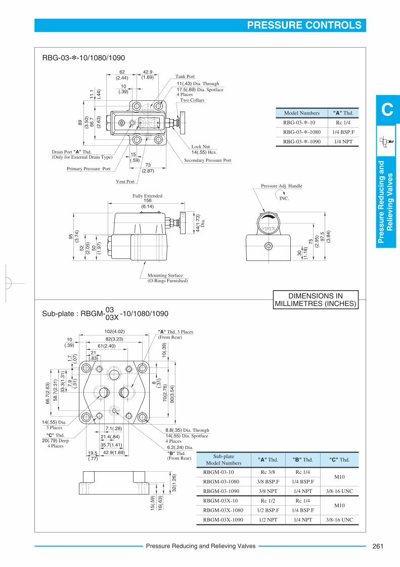
261
PRESSURE CONTROLS
Pre
ssu
reR
ed
ucin
gan
dR
elievin
gV
alv
es
C
Pressure Reducing and Relieving Valves
DIMENSIONS INMILLIMETRES (INCHES)
RBG-03-*-10
RBG-03-*-1080
RBG-03-*-1090
Model Numbers
Rc 1/4
1/4 BSP.F
1/4 NPT
"A" Thd.
RBGM-03-10
RBGM-03-1080
RBGM-03-1090
RBGM-03X-10
RBGM-03X-1080
RBGM-03X-1090
Sub-plate
Model Numbers
Rc 1/4
1/4 BSP.F
1/4 NPT
Rc 1/4
1/4 BSP.F
1/4 NPT
"A" Thd. "B" Thd. "C" Thd.
Rc 3/8
3/8 BSP.F
3/8 NPT
Rc 1/2
1/2 BSP.F
1/2 NPT
M10
M10
3/8-16 UNC
3/8-16 UNC
Tank Port
11(.43) Dia. Through
17.5(.69) Dia. Spotface 4 Places
Two Collars
Lock Nut
14(.55) Hex.
Secondary Pressure Port
Vent Port
Primary Pressure Port
Drain Port "A" Thd. (Only for External Drain Type)
Mounting Surface (O-Rings Furnished)
INC.
Pressure Adj. Handle
(6.14)
Fully Extended156
44(1
.73)
Dia
.
(1.9
7)
50
(2.0
5)
52
95
(3.7
4)
89
66.7
11.1
62
(2.44)
42.9(1.69)
10(.39)
73
(2.87)
15
(.59)
30
(1.1
8)
75
(2.9
5)
97.5
(3.8
4)
102(4.02)
82(3.23)
61(2.40)
21(.83)
33.3
(1.3
1)
10(.39)
(.31)
7.9
(.07)
1.7
(.31)
8
70(2
.76)
90(3
.54)
58.7
(2.3
1)
66.7
(2.6
3)
10(.
39)
42.9(1.69)
35.7(1.41)
19.5(.77)
21.4(.84)
32(1
.26)
16(.
63)
15(.
59)
"A" Thd. 3 Places(From Rear)
8.8(.35) Dia. Through
14(.55) Dia. Spotface 4 Places
6.2(.24) Dia.
"B" Thd. (From Rear)
14(.55) Dia. 3 Places
"C" Thd. 20(.79) Deep
4 Places
(2.6
3)
(3.5
0)
(.44)
RBG-03-*-10/1080/1090
Sub-plate : RBGM- -10/1080/109003 03X
7.1(.28)
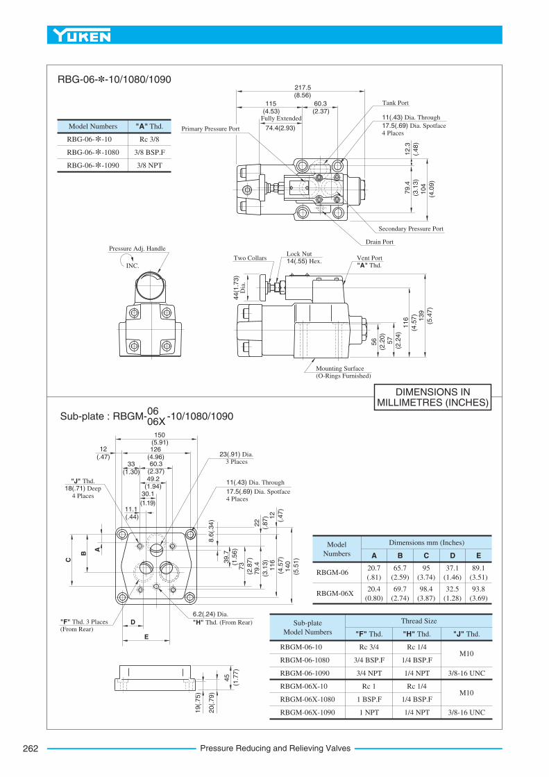
Pressure Reducing and Relieving Valves262
DIMENSIONS INMILLIMETRES (INCHES)
Model Numbers
RBG-06-*-10
RBG-06-*-1080
RBG-06-*-1090
"A" Thd.
Rc 3/8
3/8 BSP.F
3/8 NPT
Sub-plate
Model Numbers
RBGM-06
RBGM-06X
"F" Thd.
Rc 3/4
3/4 BSP.F
3/4 NPT
Model
Numbers A
RBGM-06X-10
RBGM-06X-1080
RBGM-06X-1090
Rc 1
1 BSP.F
1 NPT
Rc 1/4
1/4 BSP.F
1/4 NPT
Rc 1/4
1/4 BSP.F
1/4 NPT
"H" Thd. "J" Thd.
Thread Size
M10
3/8-16 UNC
M10
3/8-16 UNC
B C D E
Dimensions mm (Inches)
20.7
(.81)
20.4
(0.80)
69.7
(2.74)
98.4
(3.87)
65.7
(2.59)
95
(3.74)
32.5
(1.28)
93.8
(3.69)
37.1
(1.46)
89.1
(3.51)
RBGM-06-10
RBGM-06-1080
RBGM-06-1090
45
20(.
79)
19(.
75)
E
D
6.2(.24) Dia.
"H" Thd. (From Rear) "F" Thd. 3 Places(From Rear)
C
B
A
8.6
(.34)
39.7
(1.5
6)
73
(2.8
7)
79.4
(3.1
3)
116
(4.5
7)
140
(5.5
1)
12
(.47)
22
(.87)
11(.43) Dia. Through
17.5(.69) Dia. Spotface 4 Places
23(.91) Dia. 3 Places
"J" Thd. 18(.71) Deep
4 Places
11.1(.44)
30.1
(1.19)
49.2(1.94)
60.3(2.37)
33
(1.30)
12
(.47)126
(4.96)
150(5.91)
INC.
Pressure Adj. Handle
44(1
.73)
Dia
.
Two CollarsLock Nut 14(.55) Hex.
Vent Port
"A" Thd.
Mounting Surface (O-Rings Furnished)
56
(2.2
0)
57
(2.2
4)
116
(4.5
7)
139
(5.4
7)
Secondary Pressure Port
Drain Port
11(.43) Dia. Through
17.5(.69) Dia. Spotface
4 Places
Tank Port
Primary Pressure Port
Fully Extended
74.4(2.93)
115(4.53)
60.3(2.37)
217.5(8.56)
79.4
(3.1
3)
104
(4.0
9)
12.3
(.48)
Sub-plate : RBGM- -10/1080/109006 06X
RBG-06-*-10/1080/1090
(1.7
7)
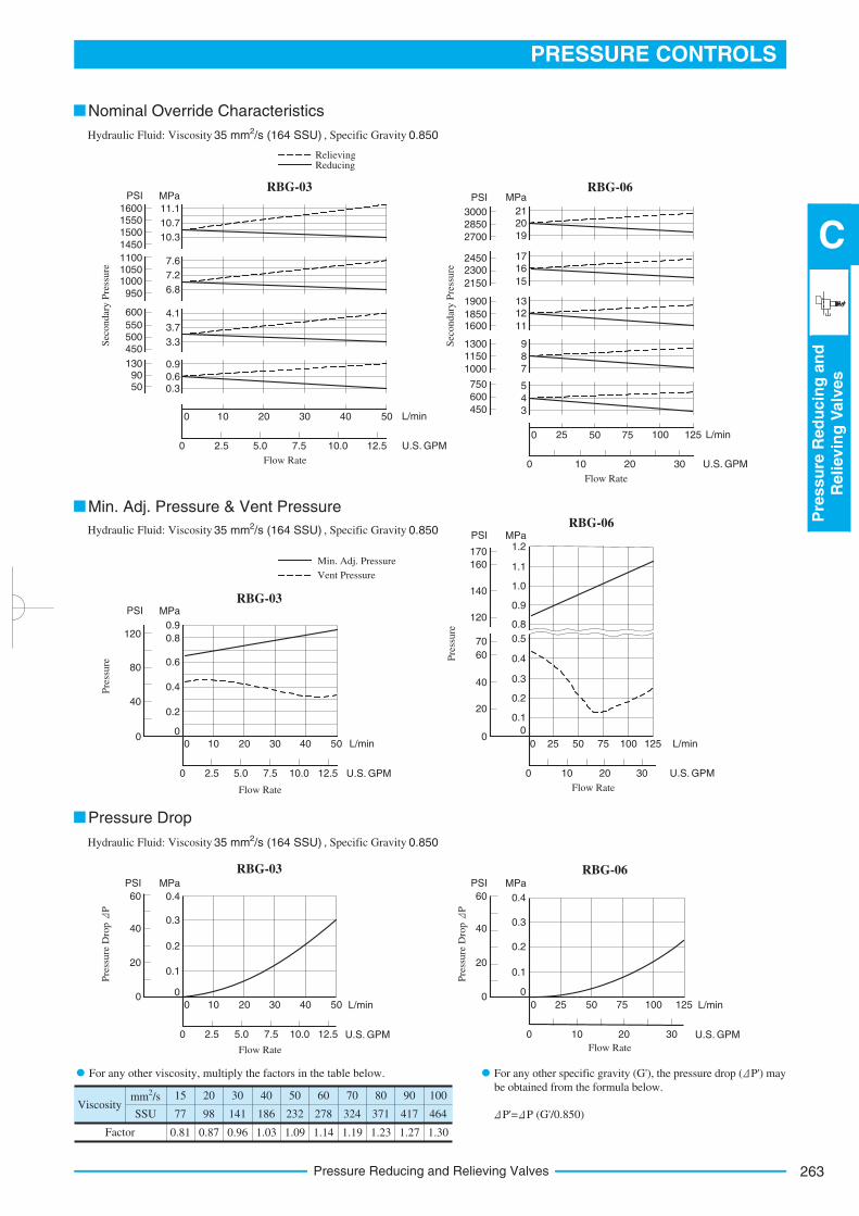
263
PRESSURE CONTROLS
Pre
ssu
reR
ed
ucin
gan
dR
elievin
gV
alv
es
C
Pressure Reducing and Relieving Valves
Viscosity
2 mm /s
SSU
Factor
15
77
0.81
20
98
0.87
30
141
0.96
40
186
1.03
50
232
1.09
60
278
1.14
70
324
1.19
80
371
1.23
90
417
1.27
100
464
1.30
MPa
2120
19
1716
15
1312
11
9
8
7
3000
PSI
Sec
ondar
y P
ress
ure
2850
2700
24502300
2150
1900
1850
1300
1150
1000
1600
750
600
4504
5
3
0 25 50 75 100 L/min
0 10 20 U.S. GPM
Flow Rate
125
30
40
20
0
60
0.2
0.1
0
0.3
0.4
0 10 20 30 40 50
2.5
PSI MPa
0 5.0 7.5 10.0 12.5
Pre
ssure
Dro
p P
40
20
0
60
0.2
0.1
0
0.3
0.4
0 25 50 75 100 125
PSI MPa
0 10 20 30
RBG-06
RBG-03 RBG-06
L/min
U.S. GPM
L/min
U.S. GPM
Pre
ssure
Dro
p P
Flow Rate Flow Rate
Hydraulic Fluid: Viscosity 2 35 mm /s (164 SSU) , Specific Gravity 0.850
Hydraulic Fluid: Viscosity 2 35 mm /s (164 SSU) , Specific Gravity 0.850
Hydraulic Fluid: Viscosity 2 35 mm /s (164 SSU) , Specific Gravity 0.850
RelievingReducing
Nominal Override Characteristics
Pressure Drop
Min. Adj. Pressure & Vent Pressure
For any other viscosity, multiply the factors in the table below.
P'= P (G'/0.850)
16001550
PSI MPa
Sec
ondar
y P
ress
ure
1500
1450
110010501000
950
600
550
1309050
11.1
10.7
10.3
7.6
7.2
6.8
4.1
3.7
3.3
0.9
0.60.3
0 10 20 30 40 L/min
0 2.5 5.0 7.5 10.0 12.5 U.S. GPM
Flow Rate
50
500450
RBG-03
80
40
0
120
0.4
0.2
0
0.6
0.8
0.9
0 10 20 30 40 50
2.5
PSI MPa
0 5.0 7.5 10.0 12.5
Pre
ssure
40
20
0
60
0.3
0.1
0
0.4
0.5
1.2
0 25 50 75 125
10
PSI MPa
0
Pre
ssure
100
20 30
1.1
1.0
0.9
0.8
0.2
RBG-03
RBG-06
70
120
140
160
170
L/min
U.S. GPM
L/min
U.S. GPM
Flow Rate Flow Rate
Vent Pressure
Min. Adj. Pressure
For any other specific gravity (G'), the pressure drop ( P') may
be obtained from the formula below.
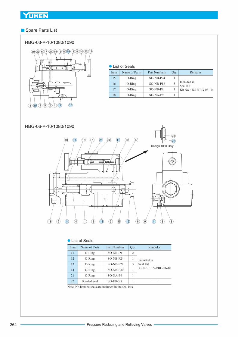
Pressure Reducing and Relieving Valves264
Spare Parts List
Item Name of Parts Part Numbers Qty. Remarks
15
16
17
18
O-Ring
O-Ring
O-Ring
O-Ring
SO-NB-P24
SO-NB-P18
SO-NB-P9
SO-NA-P9
1
3
1
1
Included in
Seal Kit
Kit No. : KS-RBG-03-10
4 3 5 2 1
19 23 6 7 21 14 13 8 11 9 10 22 12
10 16 7 20 19 17
18 5 4 1 2 3 15 6 9 8 8
Design 1080 Only
23
List of Seals
RBG-03-*-10/1080/1090
RBG-06-*-10/1080/1090
15 17 16
18
11 21 11
14 13 12 11
22
Item Name of Parts Part Numbers Qty. Remarks
11
12
13
14
21
22
O-Ring
O-Ring
O-Ring
O-Ring
O-Ring
Bonded Seal
SO-NB-P9
SO-NB-P24
SO-NB-P28
SO-NB-P30
SO-NA-P9
SG-FB-3/8
2
1
3
1
1
1
Included in
Seal Kit
Kit No. : KS-RBG-06-10
List of Seals
Note: No bonded seals are included in the seal kits.
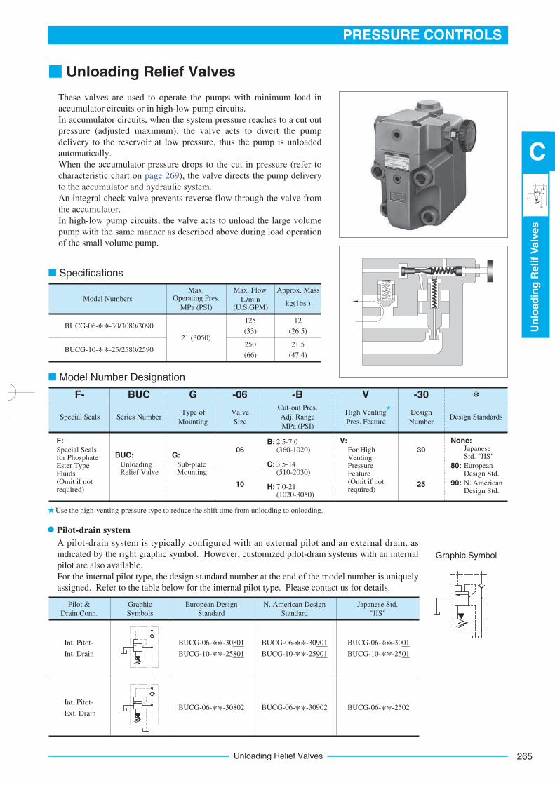
265
PRESSURE CONTROLS
Un
load
ing
Relif
Valv
es
C
Unloading Relief Valves
Unloading Relief Valves
These valves are used to operate the pumps with minimum load in
accumulator circuits or in high-low pump circuits.
In accumulator circuits, when the system pressure reaches to a cut out
pressure (adjusted maximum), the valve acts to divert the pump
delivery to the reservoir at low pressure, thus the pump is unloaded
automatically.
When the accumulator pressure drops to the cut in pressure (refer to
characteristic chart on page 269), the valve directs the pump delivery
to the accumulator and hydraulic system.
An integral check valve prevents reverse flow through the valve from
the accumulator.
In high-low pump circuits, the valve acts to unload the large volume
pump with the same manner as described above during load operation
of the small volume pump.
Special Seals Series NumberType of
Mounting
Valve
Size
Cut-out Pres.
Adj. Range
MPa (PSI)
High Venting
Pres. Feature
Design
NumberDesign Standards
F:
Special Seals for Phosphate Ester TypeFluids (Omit if not required)
BUC:
Unloading Relief Valve
G:
Sub-plate Mounting
10
06B: 2.5-7.0
(360-1020)
C: 3.5-14(510-2030)
H: 7.0-21(1020-3050)
V:
For High Venting Pressure Feature (Omit if not required)
25
30
None:Japanese Std. "JIS"
80: European Design Std.
90: N. American Design Std.
F- BUC G -06 -B V -30 *
Graphic Symbol
Model Number Designation
Use the high-venting-pressure type to reduce the shift time from unloading to onloading.
Model Numbers
Max. Operating Pres.
21 (3050)
125
(33)
MPa (PSI)
Max. Flow
L/min (U.S.GPM)
Approx. Mass
kg(1bs.)
BUCG-06-**-30/3080/3090
BUCG-10-**-25/2580/2590250
(66)
12
(26.5)
21.5
(47.4)
Specifications
Pilot-drain system
A pilot-drain system is typically configured with an external pilot and an external drain, as
indicated by the right graphic symbol. However, customized pilot-drain systems with an internal
pilot are also available.
For the internal pilot type, the design standard number at the end of the model number is uniquely
assigned. Refer to the table below for the internal pilot type. Please contact us for details.
Pilot &
Drain Conn.
Graphic
Symbols
European Design
Standard
Int. Pitot-
Int. Drain
BUCG-06-**-30801
BUCG-10-**-25801
N. American Design
Standard
BUCG-06-**-30901
BUCG-10-**-25901
Japanese Std.
"JIS"
BUCG-06-**-3001
BUCG-10-**-2501
Int. Pitot-
Ext. DrainBUCG-06-**-30802 BUCG-06-**-30902 BUCG-06-**-2502
Unloading Relief Valves266
BUCGM-06-20
BUCGM-10-20
Rc 3/4
Rc 1-1/4
Valve
Model
Numbers
Valve Model
Numbers
M16 55Lg. (2 pcs.)
M16 110Lg. (2 pcs.)
M16 130Lg. (2 pcs.)
M20 70Lg. (2 pcs.)
M20 160Lg. (4 pcs.)
5/8-11 UNC 2-1/4 Lg. (2 pcs.)
5/8-11 UNC 4-1/2 Lg. (2 pcs.)
5/8-11 UNC 5 Lg. (2 pcs.)
3/4-10 UNC 2-3/4 Lg. (2 pcs.)
3/4-10 UNC 6-1/2 Lg. (4 pcs.)
BUCG-06
BUCG-10
Japanese Std. "JIS" and European Design Std.
Socket Head Cap Screw
N. American Design Std.
BUCGM-06-2080 3/4 BSP.F
BUCGM-10-2080 1-1/4 BSP.F
Sub-plate
Model Numbers
Thread
Size
Sub-plate
Model Numbers
Thread
Size
BUCGM-06-2090 3/4 NPT
BUCGM-10-2090 1-1/4 NPT
Sub-plate
Model Numbers
Thread
Size
Japanese Standard "JIS" European Design Standard N. American Design Standard
4.4 (9.7)
7.2 (15.9)
Approx.
Mass
kg (lbs.)
BUCG-06
BUCG-10
Instructions
Mounting Bolts
Attachment
Sub-plate
Sub-plates are available. Specify the sub-plate model number from the table above. When sub-plates are not used, the mounting surface should have a good machined finish.
To adjust the pressure, loosen the lock nut and turn the pressure adjustment handle slowly clockwise for higher pressures or anti-clockwise for lower pressures. After adjustments, do not forget to tighten the lock nut.
Take care not to neglect connecting the drain pipe to the reservoir; otherwise not only will the valve fail to operate properly but also the line pressure will rise infinitely. Extend the end of the drain pipe into fluid.
Limit the pressure drop between the valve and the accumulator in an accumulator circuit below 10% of the cut-out pressure.
Limit the drain port back pressure below 2% of the cut-out pressure.
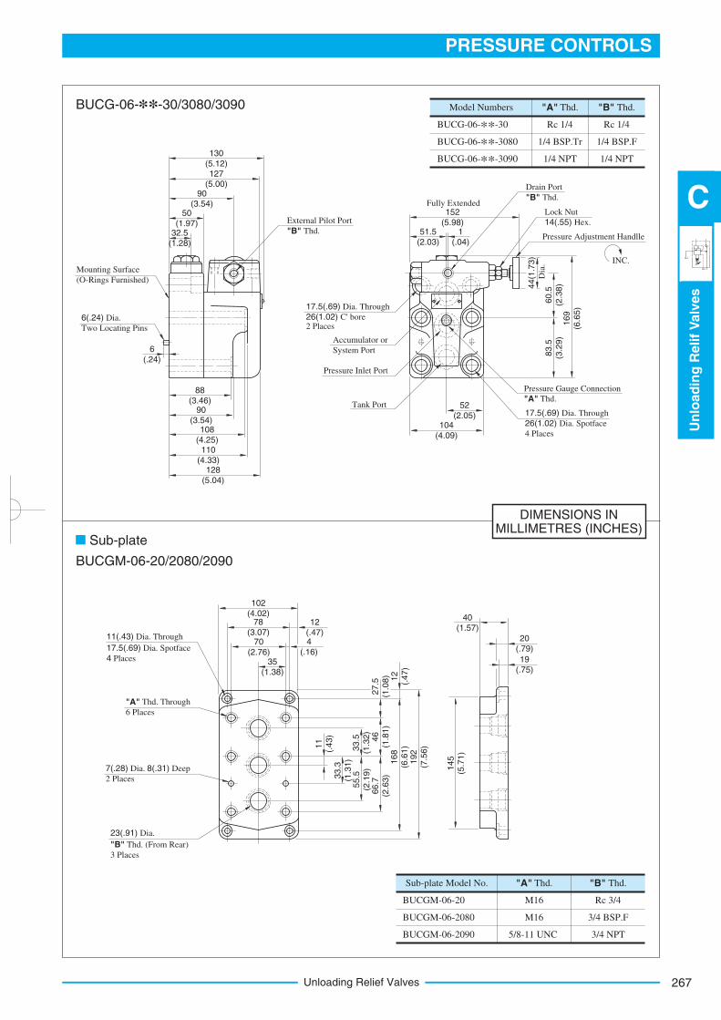
267
PRESSURE CONTROLS
Un
load
ing
Relif
Valv
es
C
Unloading Relief Valves
DIMENSIONS INMILLIMETRES (INCHES)
BUCG-06-**-30
BUCG-06-**-3080
BUCG-06-**-3090
Rc 1/4
1/4 BSP.Tr
1/4 NPT
"A" Thd.
Rc 1/4
1/4 BSP.F
1/4 NPT
"B" Thd.Model Numbers
BUCGM-06-20
BUCGM-06-2080
BUCGM-06-2090
M16
5/8-11 UNC
"A" Thd.Sub-plate Model No.
M16
"B" Thd.
Rc 3/4
3/4 BSP.F
3/4 NPT
130
(5.12)127
(5.00)90
(3.54)50
(1.97)
Mounting Surface
(O-Rings Furnished)
6(.24) Dia.
Two Locating Pins
6
(.24)
90
(3.54)
110
(4.33)128
(5.04)
External Pilot Port
"B" Thd.
Fully Extended152
(5.98)51.5
(2.03)
1
(.04)
Drain Port
"B" Thd.
Lock Nut
14(.55) Hex.
Pressure Adjustment Handlle
60.5
(2.3
8)
83.5
(3.2
9)
169
(6.6
5)
52
(2.05)104
(4.09)
17.5(.69) Dia. Through
26(1.02)2 Places
C' bore
Accumulator or
System Port
Pressure Inlet Port
Tank Port
102
(4.02)78
(3.07)70
(2.76)
12
(.47)4
(.16)35
(1.38)
11
(.43)
33.3
(1.3
1)
33.5
(1.3
2)
55.5
(2
.19)
46
(1.8
1)
66.7
(2.6
3)
27.5
(1.0
8) 12
(.47)
168
(6.6
1)
192
(7.5
6)
11(.43) Dia. Through
17.5(.69) Dia. Spotface
4 Places
"A" Thd. Through
6 Places
7(.28) Dia. 8(.31) Deep
2 Places
23(.91) Dia.
"B" Thd. (From Rear)
3 Places
40
(1.57)
20
(.79)
145
(5.7
1)
Pressure Gauge Connection
"A" Thd.
17.5(.69) Dia. Through
26(1.02) Dia. Spotface
4 Places
44(1
.73)
Dia
.
BUCG-06-**-30/3080/3090
Sub-plate
BUCGM-06-20/2080/2090
32.5
(1.28)
88
(3.46)
108
(4.25)
19
(.75)
INC.
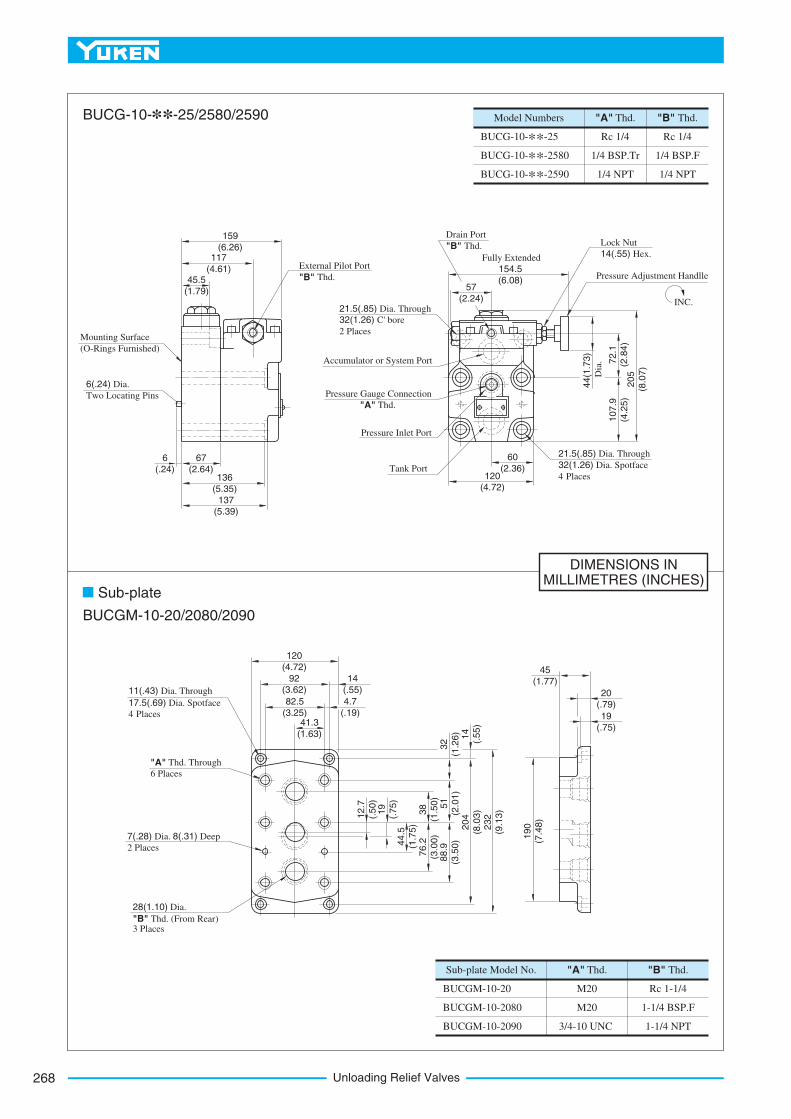
Unloading Relief Valves268
DIMENSIONS INMILLIMETRES (INCHES)
BUCG-10-**-25
BUCG-10-**-2580
BUCG-10-**-2590
Rc 1/4
1/4 BSP.Tr
1/4 NPT
"A" Thd.
Rc 1/4
1/4 BSP.F
1/4 NPT
"B" Thd.Model Numbers
BUCGM-10-20
BUCGM-10-2080
BUCGM-10-2090
M20
3/4-10 UNC
"A" Thd.Sub-plate Model No.
M20
"B" Thd.
Rc 1-1/4
1-1/4 BSP.F
1-1/4 NPT
159
(6.26)
Mounting Surface
(O-Rings Furnished)
6(.24) Dia.
Two Locating Pins
6
(.24)
External Pilot Port
"B" Thd.
Fully Extended
154.5
(6.08)57
(2.24)
Drain Port
"B" Thd. Lock Nut
14(.55) Hex.
Pressure Adjustment Handlle
72.1
(2.8
4)
107.9
(4.2
5)
60
(2.36)120
(4.72)
21.5(.85) Dia. Through
32(1.26) C' bore
2 Places
Accumulator or System Port
Pressure Inlet Port
Tank Port
120
(4.72)
92 (3.62)
82.5
(3.25)
14
(.55)
4.7
(.19)41.3
(1.63)
12.7
(.50)
11(.43) Dia. Through
17.5(.69) Dia. Spotface
4 Places
7(.28) Dia. 8(.31) Deep
2 Places
28(1.10) Dia.
"B" Thd. (From Rear)3 Places
45
(1.77)
20
(.79)
117
(4.61)
67
(2.64)
137
(5.39)
Pressure Gauge Connection
"A" Thd.
21.5(.85) Dia. Through
32(1.26) Dia. Spotface
4 Places
205
(8.0
7)
19
(.75)
44.5
(1.7
5)
38
(1.5
0)
76.2
(3.0
0)
51
(2.0
1)
88.9
(3.5
0)
204
(8.0
3)
232
(9.1
3)
32
(1.2
6) 14
(.55)
190
(7.4
8)
"A" Thd. Through
6 Places
BUCG-10-**-25/2580/2590
Sub-plate
BUCGM-10-20/2080/2090
45.5
(1.79)
136
(5.35)
19
(.75)
INC.
Dia
.
44(1
.73)
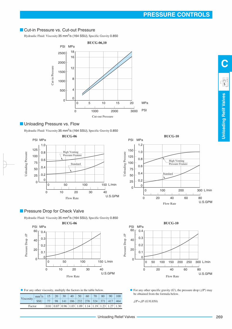
269
PRESSURE CONTROLS
Un
load
ing
Relif
Valv
es
C
Unloading Relief Valves
BUCG-06,10
Cut-out Pressure
20 MPa
3000 PSI200010000
15100 5
Cut-
in P
ress
ure
182500
MPaPSI
8
4
0
16
12
2000
1500
1000
500
0
BUCG-06
Unlo
adin
g P
ress
ure
1.0
MPaPSI
0.8
0.6
0.4
0.2
0
125
100
75
50
25
0150 L/min
40
U.S.GPM
10050
3020100
Flow Rate
High Venting
Pressure Feature
Standard
BUCG-10
1.2
MPaPSI
1501.0
0.8
0.6
0.4
0.20
0
0
125
100
75
50
25
0
Unlo
adin
g P
ress
ure
300 L/min
80
U.S.GPM
200100
6040200
Flow Rate
High Venting Pressure Feature
Standard
BUCG-06
0.4
MPaPSI
60
0.3
0.2
0.1
0
40
20
0150 L/min
40
U.S.GPM
10050
3020100
Flow Rate
Pre
ssure
Dro
p P
0.4
MPaPSI60
0.3
0.2
0.1
0 0
0
40
20
0300 L/min
80
U.S.GPM
25020015010050
6040200
Flow Rate
Pre
ssure
Dro
p P
BUCG-10
Cut-in Pressure vs. Cut-out Pressure
Unloading Pressure vs. Flow
Pressure Drop for Check Valve
Hydraulic Fluid: Viscosity 2 35 mm /s (164 SSU), Specific Gravity 0.850
Hydraulic Fluid: Viscosity 2 35 mm /s (164 SSU), Specific Gravity 0.850
Hydraulic Fluid: Viscosity 2 35 mm /s (164 SSU), Specific Gravity 0.850
Viscosity
2 mm /s
SSU
Factor
15
77
0.81
20
98
0.87
30
141
0.96
40
186
1.03
50
232
1.09
60
278
1.14
70
324
1.19
80
371
1.23
90
417
1.27
100
464
1.30
For any other viscosity, multiply the factors in the table below.
P'= P (G'/0.850)
For any other specific gravity (G'), the pressure drop ( P') may
be obtained from the formula below.
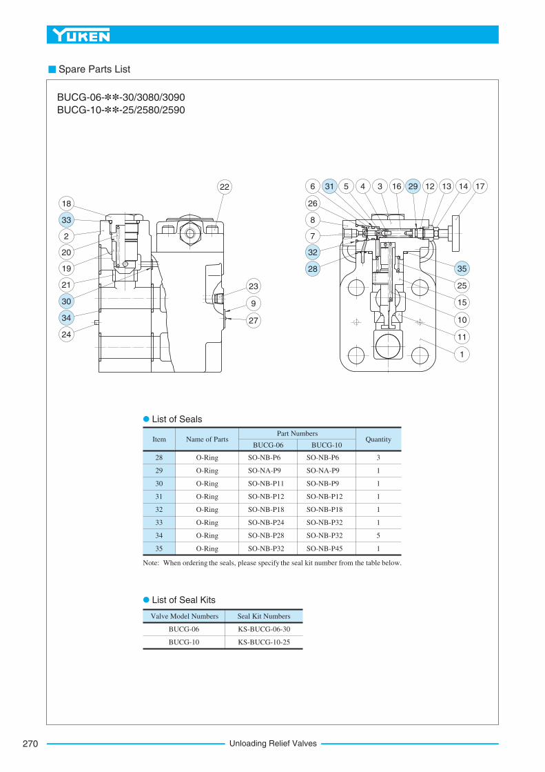
Unloading Relief Valves270
Spare Parts List
O-Ring28 SO-NB-P6 3
O-Ring29 1
O-Ring30 1
O-Ring31 1
O-Ring32 1
O-Ring33 1
O-Ring34 5
O-Ring35 1
Item Name of PartsBUCG-06
Part Numbers
BUCG-10Quantity
SO-NA-P9
SO-NB-P11
SO-NB-P12
SO-NB-P18
SO-NB-P24
SO-NB-P28
SO-NB-P32
SO-NB-P6
SO-NA-P9
SO-NB-P9
SO-NB-P12
SO-NB-P18
SO-NB-P32
SO-NB-P32
SO-NB-P45
Valve Model Numbers Seal Kit Numbers
BUCG-06
BUCG-10
KS-BUCG-06-30
KS-BUCG-10-25
18
2
20
19
21
24
22
23
9
27
BUCG-06-**-30/3080/3090
BUCG-10-**-25/2580/2590
List of Seals
Note: When ordering the seals, please specify the seal kit number from the table below.
List of Seal Kits
7
8
26
6 5 4 3 16 12 13 14 17
25
15
11
1
10
33
30
34
28
32
31 29
35
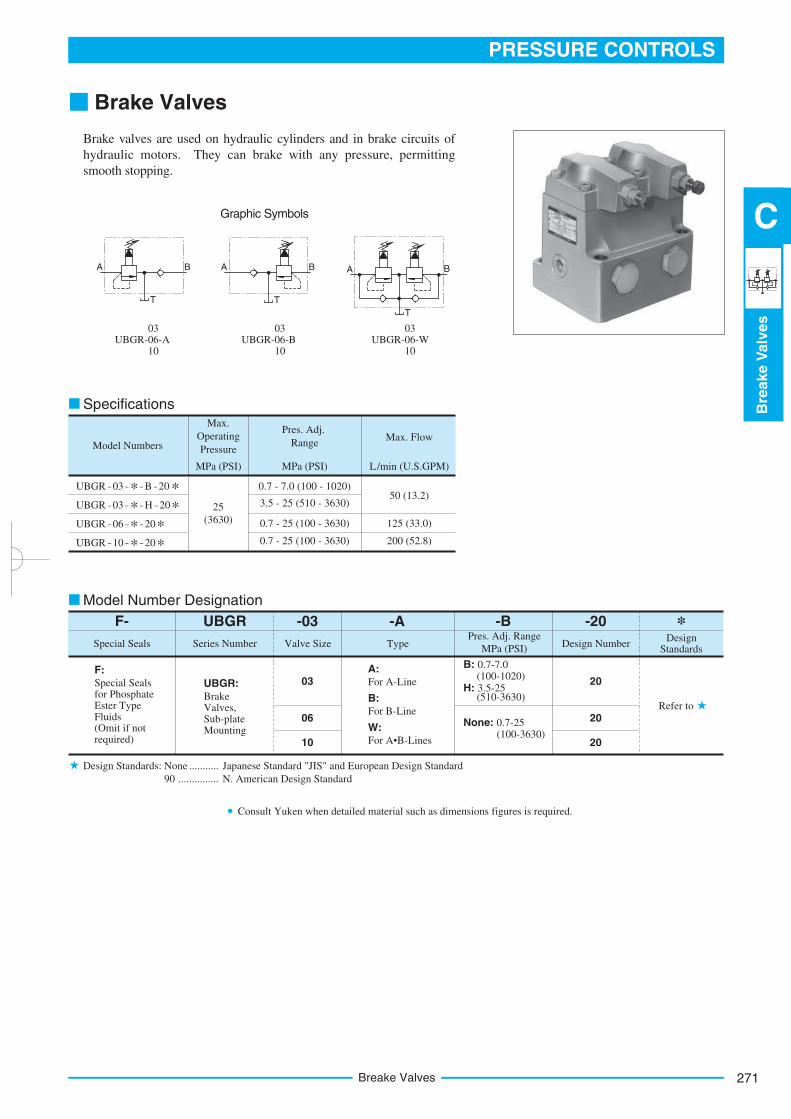
271
PRESSURE CONTROLS
Bre
ake
Valv
es
C
Breake Valves
Brake Valves
Brake valves are used on hydraulic cylinders and in brake circuits of
hydraulic motors. They can brake with any pressure, permitting
smooth stopping.
UBGR – 03 – * – B – 20 *UBGR – 03 – * – H – 20*UBGR – 06 – * – 20*UBGR – 10 – * * – 20
Graphic Symbols
A B
T
A B
T
A B
T
UBGR-06-A03
10UBGR-06-B
03
10UBGR-06-W
03
10
Model Numbers
Max.
Operating
Pressure
MPa (PSI)
Pres. Adj.
Range
MPa (PSI)
Max. Flow
L/min (U.S.GPM)
0.7 - 7.0 (100 - 1020)
3.5 - 25 (510 - 3630)25
(3630) 0.7 - 25 (100 - 3630)
0.7 - 25 (100 - 3630)
50 (13.2)
125 (33.0)
200 (52.8)
F- *UBGR -03 -B -20
Series NumberSpecial SealsDesign
StandardsDesign Number
Pres. Adj. Range
MPa (PSI)Valve Size
Refer to
20
20
20
03
06
10
F:Special Seals for Phosphate Ester Type Fluids (Omit if not required)
UBGR:BrakeValves,Sub-plateMounting
B: 0.7-7.0 (100-1020)
H: 3.5-25 (510-3630)
None: 0.7-25 (100-3630)
Specifications
Model Number Designation
Design Standards: None Japanese Standard "JIS" and European Design Standard...........
-A
Type
A:
For A-Line
B:
For B-Line
W:
For A•B-Lines
90 N. American Design Standard...............
Consult Yuken when detailed material such as dimensions figures is required.
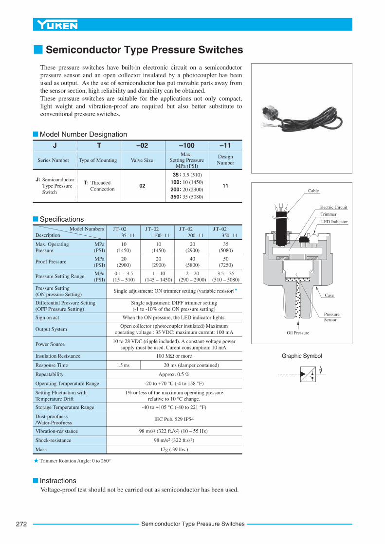
Semiconductor Type Pressure Switches272
Semiconductor Type Pressure Switches
These pressure switches have built-in electronic circuit on a semiconductor
pressure sensor and an open collector insulated by a photocoupler has been
used as output. As the use of semiconductor has put movable parts away from
the sensor section, high reliability and durability can be obtained.
These pressure switches are suitable for the applications not only compact,
light weight and vibration-proof are required but also better substitute to
conventional pressure switches.
J
Series Number
T
Type of Mounting
–02
Valve Size
–11
Design
Number
J: Semiconductor
Type Pressure
Switch
T: Threaded
Connection1102
–100
Max. Setting Pressure
MPa (PSI)
35 3.5 (510)
100:
:
:
:
10 (1450)
200 20 (2900)
350 35 (5080)
Model Numbers JT – 02
– 35 – 11
JT – 02
– 100 – 11
JT – 02
– 200 – 11
JT – 02
– 350 – 11
Max. Operating
Pressure
Proof Pressure
Pressure Setting Range
Pressure Setting
(ON pressure Setting)
Differential Pressure Setting
(OFF Pressure Setting)
Sign on act
Output System
Power Source
Insulation Resistance
Response Time
Repeatability
Operating Temperature Range
Setting Fluctuation with
Temperature Drift
Storage Temperature Range
Dust-proofness
/Water-Proofness
Vibration-resistance
Shock-resistance
Mass
MPa
(PSI)
MPa
(PSI)
MPa
(PSI)
10
(1450)
20
(2900)
0.1 – 3.5
(15 – 510)
10
(1450)
20
(2900)
1 – 10
(145 – 1450)
20
(2900)
40
(5800)
2 – 20
(290 – 2900)
35
(5080)
50
(7250)
3.5 – 35
(510 – 5080)
Single adjustment: ON trimmer setting (variable resistor)
Single adjustment: DIFF trimmer setting
(-1 to -10% of the ON pressure setting)
When the ON pressure, the LED indicator lights.
Open collector (photocoupler insulated) Maximum
operating voltage : 35 VDC; maximum current: 100 mA
10 to 28 VDC (ripple included). A constant-voltage power
supply must be used. Curent consumption: 10 mA.
100 MΩ or more
1.5 ms 20 ms (damper contained)
Approx. 0.5 %
-20 to +70 °C (-4 to 158 °F)
1% or less of the maximum operating pressure
relative to 10 °C change.
-40 to +105 °C (-40 to 221 °F)
IEC Pub. 529 IP54
98 m/s2 (322 ft./s2) (10 – 55 Hz)
98 m/s2 (322 ft./s2)
17g (.39 lbs.)
Trimmer Rotation Angle: 0 to 260°
Voltage-proof test should not be carried out as semiconductor has been used.
Graphic Symbol
Oil Pressure
Pressure
Sensor
Case
Cable
Electric Circuit
Trimmer
LED Indicator
Model Number Designation
Specifications
Description
Instractions
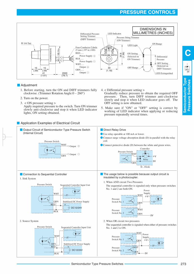
273
PRESSURE CONTROLS
Sem
ico
nd
ucto
rTyp
eP
ressu
reS
wit
ch
es
C
Semiconductor Type Pressure Switches
DIMENSIONS INMILLIMETRES (INCHES)
Adjustment
Output Circuit of Semiconductor Type Pressure Switch(Internal Circuit)
Application Examples of Electrical Circuit
Direct Relay Drive
Use relay operable at 100 mA or lower.
Connect surge voltage absorption diode (D) in parallel with the relay
coil.
Connect pretective diode (D) between the white and green wires.
Connection to Sequential Controller
1. Sink System
The usage below is possible because output circuit isinsulated by a photocoupler.
1. When AND circuit Two Pressures
The sequential controller is signaled only when pressure switches
No. 1 and 2 are both ON.
2. Source System 2. When OR circuit two pressures
The sequential controller is signaled when either of pressure switches
No. 1 and 2 is ON.
DIFF. ON
YU
KW
N K
OG
YO
15(.59) (.59) (1.18)
15
41(1.61) (78.7)
2000
34
.6(1
.36
)
30
R 1/4 Thd.
Four-Conductor Cabele
(5 mm (.197 in.) OD)
RED......
Power Supply
BLK......
Power Supply
WHT......
Output
GRN......
Output
LED Indicator
Pressure Stting Trimmer
(ON Trimmer)
Differential PressureSetting Trimmer
ON Range
Differential
Pressure
OFF Setting
(Selected on
DIFF Trimmer)
LED Light
LED Extinguished
OFF Range
ON Setting
(Selected on
ON Trimmer)
Pressure Switch
WHT
GRN
Output
Output
D
V
0VD
D... Diode
Pressure SwitchWHT
GRN
Controller
Relay
DC12/24V
DC12/24V
Pressure Switch
WHT
GRN
BLK
Sequential Controller Input Unit
Stabilized DC Power Supply
Pressure Switch
WHT
BLK
Sequential Controller Input Unit
Stabilized DC Power Supply
Pressure
Switch No. 1
Pressure
Switch No. 20V
WHT
GRN
WHT
GRN
Power
Supply
V
0V
Pressure
Switch No. 1
Pressure
Switch No. 2
WHT
GRN
Power
Supply
V
PRESSURE SWITCH
1. Before starting, turn the ON and DIFF trimmers fully clockwise. (Trimmer Rotation Angle:0 – 260°)
2. Turn on the power.
3. < ON pressure setting >Apply required pressure to the switch. Turn ON trimmer slowly anti-clockwise and stop it when LED indicator lights, ON setting obtained.
4. < Differntial pressure setting >Gradually reduce pressure to obtain the required OFF pressure. Then, turn DIFF trimmer anti-clockwise slowly and stop it when LED indicator goes off. The OFF setting is now obtained.
5. Make sure if "ON" or "OFF" setting is correct by working of LED indicator when applying or reducing pressure repeatedly several times.
RED
RED
GRN
WHT
GRN
30 (
1.1
8)
Dia
.
(DIFF Trimmer)
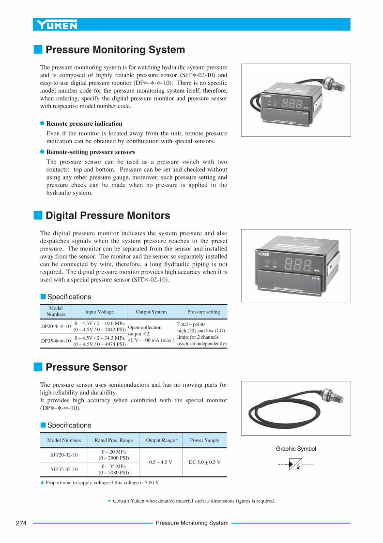
Pressure Monitoring System274
Graphic Symbol
Pressure Monitoring System
The pressure monitoring system is for watching hydraulic system pressure
and is composed of highly reliable pressure sensor (SJT*-02-10) and
easy-to-use digital pressure monitor (DP*-*-*-10). There is no specific
model number code for the pressure monitoring system itself, therefore,
when ordering, specify the digital pressure monitor and pressure sensor
with respective model number code.
Digital Pressure Monitors
The digital pressure monitor indicates the system pressure and also
despatches signals when the system pressure reaches to the preset
pressure. The monitor can be separated from the sensor and installed
away from the sensor. The monitor and the sensor so separately installed
can be connected by wire, therefore, a long hydraulic piping is not
required. The digital pressure monitor provides high accuracy when it is
used with a special pressure sensor (SJT*-02-10).
Pressure Sensor
The pressure sensor uses semiconductors and has no moving parts for
high reliability and durability.
It provides high accuracy when combined with the special monitor
(DP*-*-*-10).
Remote pressure indication
Even if the monitor is located away from the unit, remote pressure
indication can be obtained by combination with special sensors.
Remote-setting pressure sensors
The pressure sensor can be used as a pressure switch with two
contacts: top and bottom. Pressure can be set and checked without
using any other pressure gauge, moreover, such pressure setting and
pressure check can be made when no pressure is applied in the
hydraulic system.
Specifications
Model
NumbersInput Voltage Output System Pressure setting
DP20-*-*-10
DP35-*-*-10
0 – 4.5V / 0 – 19.6 MPa
(0 – 4.5V / 0 – 2842 PSI)Total 4 points:
high (HI) and low (LO)
limits for 2 channels
(each set independently)0 – 4.5V / 0 – 34.3 MPa
(0 – 4.5V / 0 – 4974 PSI)
Open-collection
output 2,
40 V - 100 mA (max.)
Specifications
Model Numbers Rated Pres. Range Output Range Power Supply
SJT20-02-10
SJT35-02-10
0 – 20 MPa
(0 – 2900 PSI)
0 – 35 MPa
(0 – 5080 PSI)
0.5 – 4.5 V DC 5.0 +_ 0.5 V
Proportional to supply voltage if this voltage is 5.00 V
Consult Yuken when detailed material such as dimensions figures is required.