Ventile BM USLetter 05-12-2011 - stauff.com ONE/NoAm-Version... · Technical Appendix F110 ......
120
Index F2 High-Pressure Two-Way Ball Valves F4 High-Pressure Three-Way Ball Valves F44 High-Pressure Four-Way Ball Valves F66 Medium- / Low-Pressure Ball Valves F74 Flow Control Valves F82 Gauge Isolator Valves F96 Accessories / Options F98 Special Application Valves F106 Technical Appendix F110 STAUFF Ball Valves are designed for use as on/off devices and must not be used to throttle fluid flow. Use in any position other than fully open or fully closed can lead to rapid deterioration of valve components and possible product failure. When operated from the fully closed position at rated operating pressure, manual operation may prove difficult due to opening torque requirements. Please consult factory prior to field application. "Floating Ball" design insures a positive, leak-free seal and automatically compensates for any seat wear or misalignment. Available in Carbon Steel and Stainless Steel. 1/4 turn positive operation. Hard-chrome plated micro-smooth ball greatly reduces friction and seat wear. Ball seats are available in a variety of materials to suit your special applications. Depending on size and materials, working pressures up to 800 bar / 12000 PSI and temperatures up to +500 °C / +930 °F can be accommodated. Full size ports on most two-way valves virtually eliminates pressure drop. STAUFF Ball Valves offer completely bidirectional operation, eliminating any chance of incorrect installation. No lubrication or maintenance required for the life of the valve. STAUFF Valves are easily and completely repairable. Long seal life. No threads in fluid service to contaminate flow or cause turbulence. Please note: Ball Valve Selection Chart 40 33 26 20 13 7 3 Size 24 Size 32 Size 04 Size 06 Size 08 Size 12 Size 16 Size 20 3 5 10 15 20 30 50 80 100 150 185 Q in l/min 12,2 10,1 7,9 6,1 4 2,1 0,9 Machined slot indicates ball bore position. Machined stop pin assures positive closing / opening, eliminates seat degradation due to ball misalignment. Blow out proof stem design. Bottom loaded for safety. Primary stem seals made of Delrin® (POM), also acting as a bearing surface between body and stem. O-rings made of FPM (Viton®) are standard. NBR (Buna-N®) and EPDM sealings available. Micro smooth Carbon Steel (hard-chrome plated) or Stainless Steel ball. NPT, SAE, BSP, ORFS, Metric and SAE flanged connectors are available. Heavy-duty body. Ball seats made of Delrin® (POM) to assure low operating torque. Special ball seat materials available. Secondary stem seals made of FPM (Viton®) are standard. NBR (Buna-N®) and EPDM sealings available. V in ft/s V in m/s Main Features Alternative lever designs and materials Special ball seat and O-ring materials for lower/higher temperatures and more aggressive media Special threads and connections Accessories Locking devices Actuator packages Limit switches Special Versions Highest-pressure ball valves High-temperature ball valves Ball valves for gas, paints, lacquers and Isocyanate Ball valves with fire-safe approval Custom-designed ball valves Contact STAUFF with your special requirements. Options 0,8 1,3 2,6 3,9 5,2 7,8 13 21 26 39 48 Q in US GPM F Valves Valves F
-
Upload
phunghuong -
Category
Documents
-
view
219 -
download
0
Transcript of Ventile BM USLetter 05-12-2011 - stauff.com ONE/NoAm-Version... · Technical Appendix F110 ......

Index F2
High-Pressure Two-Way Ball Valves F4
High-Pressure Three-Way Ball Valves F44
High-Pressure Four-Way Ball Valves F66
Medium- / Low-Pressure Ball Valves F74 Flow Control Valves F82
Gauge Isolator Valves F96 Accessories / Options F98
Special Application Valves F106
Technical Appendix F110
STAUFF Ball Valves are designed for use as on/off devices and must not be used to throttle fluid flow. Use in any position other than fully open or fully closed can lead to rapid deterioration of valve components and possible product failure.
When operated from the fully closed position at rated operating pressure, manual operation may prove difficult due to opening torque requirements.
Please consult factory prior to field application.
� "Floating Ball" design insures a positive, leak-free seal and automatically compensates for any seat wear or misalignment.
� Available in Carbon Steel and Stainless Steel. � 1/4 turn positive operation. � Hard-chrome plated micro-smooth ball greatly reduces friction and seat wear.
� Ball seats are available in a variety of materials to suit your special applications.
� Depending on size and materials, working pressures up to 800 bar / 12000 PSI and temperatures up to +500 °C / +930 °F can be accommodated.
� Full size ports on most two-way valves virtually eliminates pressure drop.
� STAUFF Ball Valves offer completely bidirectional operation, eliminating any chance of incorrect installation.
� No lubrication or maintenance required for the life of the valve. � STAUFF Valves are easily and completely repairable. � Long seal life. � No threads in fluid service to contaminate flow or cause turbulence.
Please note: Ball Valve Selection Chart
40
33
26
20
13
7
3
Size 24
Size 32
Size 04 Size 06 Size 08 Size 12 Size 16 Size 20
3 5 10 15 20 30 50 80 100 150 185 Q in l/min
12,2
10,1
7,9
6,1
4
2,1
0,9
Machined slot indicates ball bore position.
Machined stop pin assures positive closing / opening, eliminates seat degradation due to ball misalignment.
Blow out proof stem design. Bottom loaded for safety.
Primary stem seals made of Delrin® (POM), also acting as a bearing surface between body and stem.
O-rings made of FPM (Viton®) are standard. NBR (Buna-N®) and EPDM sealings available.
Micro smooth Carbon Steel (hard-chrome plated) or Stainless Steel ball.
NPT, SAE, BSP, ORFS, Metric and SAE flanged connectors are available.
Heavy-duty body.
Ball seats made of Delrin® (POM)
to assure low operating torque. Special ball seat materials available.
Secondary stem seals made of FPM (Viton®) are standard. NBR (Buna-N®) and EPDM sealings available.
V in
ft/s
V in
m/s
Main Features
� Alternative lever designs and materials � Special ball seat and O-ring materials for lower/higher temperatures and more aggressive media
� Special threads and connections Accessories
� Locking devices � Actuator packages � Limit switches
Special Versions
� Highest-pressure ball valves � High-temperature ball valves � Ball valves for gas, paints, lacquers and Isocyanate � Ball valves with fire-safe approval � Custom-designed ball valves
Contact STAUFF with your special requirements.
Options
0,8 1,3 2,6 3,9 5,2 7,8 13 21 26 39 48 Q in US GPM
FValves
Valv
esF
Ventile_BM_USLetter_05-12-2011.indd 1 20.02.2014 10:23:31

F2 www.stauff.com
Index
High Pressure Two-Way Ball Valves
High-Pressure Three-Way Ball Valves
High-Pressure Block Body Ball ValveL-Bore Three-Way SelectorIntroduction
BBV35 F44
Manifold Mounting F45
High-Pressure Block Body Ball ValveL-Bore Three-Way Selector - Introduction
BBVS35 F46
Manifold Mounting F47
High-Pressure Block Body Ball ValveL-Bore Three-Way Selector - Introduction
CBV3 F48
Female NPT / BSP Thread F49Female UN/UNF Thread F5024° Cone Connection - Light / Heavy Series F51
High-Pressure Block Body Ball ValveL-Bore Three-Way Selector - Introduction
CBV38 F52
6000 PSI SAE Flange Connection F53
High-Pressure Block Body Ball ValveL-Bore Three-Way Selector - Introduction
CBVS3 F54
Female NPT / BSP Thread F55Female UN/UNF Thread F5624° Cone Connection - Light / Heavy Series F57
High-Pressure Block Body Ball ValveL-Bore Three-Way Selector - Introduction
LBV3 F58
Female NPT / BSP Thread F59Female UN/UNF Thread F6024° Cone Connection - Light / Heavy Series F61
High-Pressure Block Body Ball ValveT-Bore Three-Way Selector - Introduction
TBV3 F62
Female NPT / BSP Thread F63Female UN/UNF Thread F6424° Cone Connection - Light / Heavy Series F65
High-Pressure Block Body Ball ValveIntroduction
BBV F4
Female NPT / BSP Thread F5Female UN / UNF Thread F6O-Ring Face Seal Connection - Male Thread F624° Cone Connection - Light / Heavy Series F7
High-Pressure Block Body Ball Valve(Medium Duty) Introduction
BBVM F8
Female NPT Thread F9Female UN / UNF Thread F10
High-Pressure Forged Body Ball ValveIntroduction
FBV F11
Female NPT / BSP Thread F12Female UN / UNF Thread F12O-Ring Face Seal Connection - Male Thread F1324° Cone Connection - Light / Heavy Series F13
High-Pressure 800 bar / 12000 PSIBlock Body Ball ValveIntroduction
HBV F14
Female NPT Thread F1524° Cone Connection - Heavy Series F15
High-Pressure Block Body Ball ValveIntroduction
BBV22/23 F16
3000 PSI SAE Split Flange Connection F176000 PSI SAE Split Flange Connection F17
High-Pressure Forged Body Ball ValveIntroduction
FBV22/23 F18
3000 PSI SAE Split Flange Connection F196000 PSI SAE Split Flange Connection F19
High-Pressure Block Body Ball ValveIntroduction
BBV2H/2T F20
3000 PSI SAE Split Flange / Flange Connection F216000 PSI SAE Split Flange / Flange Connection F21
High-Pressure Block Body Ball ValveIntroduction
BBV2E/2S F22
3000 PSI SAE Flange Connection F236000 PSI SAE Flange Connection F23
High-Pressure Forged Body Ball ValveIntroduction
FBV2H/2T F24
3000 PSI SAE Split Flange / Flange Connection F256000 PSI SAE Split Flange / Flange Connection F25
High-Pressure Forged Body Ball ValveIntroduction
FBV2E/2S F26
3000 PSI SAE Flange Connection F276000 PSI SAE Flange Connection F27
High-Pressure Round Body Ball ValveIntroduction
BBV29 F28
3000/6000 PSI Flange Connection F29
High-Pressure Round Body Ball ValveIntroduction
BBV27/28 F30
3000 PSI Flange Connection F316000 PSI Flange Connection F31
High-Pressure Round Body Ball ValveIntroduction
BBVF2A F32
DIN Flange Connection with SCH 160 Butt Weld Ends F33
High-Pressure Round Body Ball ValveIntroduction
BBV2D1/D2 F34
ISO Flange Connection F35
High-Pressure Round Body Ball ValveIntroduction
BBV2Y1/Y2 F36
CETOP Flange Connection F37
High-Pressure Block Body Ball ValveIntroduction
KHZ27/28 F38
3000 PSI SAE Flange Connection F396000 PSI SAE Flange Connection F40
High-Pressure Block Body Ball ValveIntroduction
BBV25 F42
Manifold Mounting F43
High-Pressure Block Body Ball ValveT-Bore Four-Way Selector - Introduction
TBV4 F66
Female BSP / NPT Thread F67Female UN/UNF Thread F6824° Cone Connection - Light / Heavy Series F69
High-Pressure Block Body Ball ValveDouble L-Bore Four-Way Selector - Introduction
XBV4 F70
Female BSP / NPT Thread F71Female UN/UNF Thread F7224° Cone Connection - Light / Heavy Series F73
High-Pressure Four-Way Ball Valves
Ventile_BM_USLetter_05-12-2011.indd 2 20.02.2014 10:23:41

Valv
esF
www.stauff.com F3
Index
Medium- / Low-Pressure Ball Valves
Accessories / Options
Levers F98Locking Device LD F99Double-Acting Pneumatic Actuator EDA F102Single-Acting Pneumatic Actuator ESA F102Limit Switches F102Ball Valves with Detent F103Ball Valves with Assembly Holes F103Ball Valves with Assembly Threads F103Alternative Porting Patterns F104
Special Application Valves
Highest-Pressure Ball Valves F106High-Temperature Ball Valves F107Ball Valves for Gas Applications F108Ball Valves for Paints and Lacquers F108Ball Valves for Isocyanates F108Ball Valves with Fire-Safe Approval F109
Technical Appendix
Nomenclature Definitions F110Standard Materials F110Admissible Working Pressures F111Surface Coatings F111Determination of Nominal Diameters F112Sealing Variations F113Torque Figures F114Pressure Equipment Directive F115CE-Marking of STAUFF Valves F115Storing and Assembling Instructions F115Seal Kits F116Tightening Torques of Adaptors and Endcaps F118
Gauge Isolator Valves
Gauge Isolator Valve(Single Station)
SWS-S1 F96
Gauge Isolator Valve(Multi Station)
SWS-M F96
Gauge Isolator Needle Valve(Single Station)
SWS-A1/A2 F97
Flow Control Valves
Heavy-Duty Throttle / Shut-Off Valve(In-Line Assembly)
DV F82
Heavy-Duty Flow Control Valve(In-Line Assembly)
DRV F83
Medium-Duty Throttle / Shut-Off Valve(In-Line Assembly)
NVH F84
Medium-Duty Flow Control Valve (In-Line Assembly)
FCH F85
Medium-Pressure Brass Throttle / Shut-Off Valve (In-Line Assembly)
NVM F86
Medium-Pressure Brass Flow Control Valve(In-Line Assembly)
FCM F87
Throttle / Shut-Off Valve(Manifold Assembly)
DVP F88
Flow Control Valve(Manifold Assembly)
DRVP F89
Throttle / Shut-Off Valve(Cartridge Assembly)
DVE F90
Pressure Compensated Flow Control Valve(In-Line Assembly)
PNDRV F91
Heavy-Duty Check Valve(In-Line Assembly)
RV F92
Medium-Duty Check Valve(In-Line Assembly)
RVM F93
Flow Characteristics F94
Medium-Pressure Ball Valve 2BVM F74Two-Piece Hex Body Ball Valve
Low-Pressure Ball Valve 2BVL F75Two-Piece Brass Body Ball Valve
Port Adaptors F77
Medium-Pressure Hex Body Ball Valve 2BVM F79Two-Piece Stainless Steel Body
Medium-Pressure Hex Body Ball Valve 2BVM3 F80Two-Piece Stainless Steel Body
Medium-Pressure Hex Body Ball Valve 3BVM F81Three-Piece Stainless Steel Body
Ventile_BM_USLetter_05-12-2011.indd 3 20.02.2014 10:31:31
High-Pressure Two-Way Ball Valves
F4� �����������
Introduction
High-Pressure Block Body Ball Valve � Type BBV List of ComponentsNo. Qty. Description1 1 Housing2 1 Ball3* 2 Seat4* 2 Connector O-Ring5 2 Connector6 1 Stop Pin7 1 Stem8* 1 Thrust Ring9* 1 Stem O-Ring10 1 Cam Plate11 1 Snap Ring12 1 Lever13 1 ���� ���14 1 �������������* Included in seal kit
K - - - K K 2 0 02 0 0 0 2 2 0 0 BBV 02 02 0 0 0 0 0 0 1 1 -
Order Codes
� TypeHigh-Pressure Block Body Ball Valve BBV
� Number of Ports������������������������������ 2
� Connection Style�������!����"������#! ���$�%&�$�� 0Female BSP Thread (DIN ISO 228) GFemale UN/UNF Thread (SAE J 514) 1Male O-Ring Face Seal Connection B
�������������� �#'����������������������������������
� Connection Size
�������������� �#'�����������������������������+���
� Body Material / Surface FinishingCarbon Steel, zinc/iron-plated 0Stainless Steel V4A (AISI 316Ti) 1
#���������������������.�������:���"��;������������<���=�����>������?������� �#'���������"��������������
� Ball / Stem MaterialBall: Carbon Steel, hard chrome-platedStem: Carbon Steel
0
Ball / Stem: Stainless Steel V4A (AISI 316Ti) 1
#���������������������.�������:���"��;������������<���=�����>������?������� �#'���������"��������������
� Ball Seat MaterialDelrin® (POM) 0
#�������������������������������<����=�����>������?������� �#'���������"��������������
O-Ring MaterialNBR (Buna-N®) 0FPM (Viton®) 1EPDM 3
#�������������������������������<����=�����>������?������� �#'���������"��������������
Manufacturing Code Manufacturing code for all connection styles��G�=���������!����"�������
M
Manufacturing code (only for Female NPT Thread) KManufacturing code for high-pressure versionof connection styles 0 and 1 (STAUFF Size 16)
H
� Lever Options �==��������"�����������������������;������<��� - �==��������"��������� -0
#���������������������<������������=�������������������=�;���KQ�������"��������������
� Accessories / Options �==��������"������������� - �==��������"�W�X��;�Y�����WY$ -LD1 �==��������"�W�X��;�Y�����WY% -LD2 �==��������"�W�X��;�Y�����WYZ����������[1) -LD3 �==��������"�W�X��;�Y�����WY\ -LD4 �==��������"�Y��<���#���;���������Actuator (Please add size **)
-EDA**
�==��������"� ��;���#���;���������Actuator (Please add size **)
-ESA**
�==��������"�W����� ���"�����=���=������� �LS-O �==��������"�W����� ���"����������=������� �LS-C �==��������"�W����� ���"�����=������closed position -LS-OC
*1 LD4 is the standard locking device option for the"�;"�=��������������������������;�����]�������������=�;���KK�������"��������������
STAUFF Size (according to dimension table)for connection styles 0, G, 1 and B:
02 04 06 08 10 12 16
DN04 DN06 DN08 DN10 DN13 DN16 DN20 DN25
Tube Size (according to dimension table)for 24° Cone Connection (Heavy Series):06S 08S 10S 12S 14S 16S 20S 25S 30S 38S
Tube Size (according to dimension table)for 24° Cone Connection (Light Series):06L 08L 10L 12L 15L 18L 22L 28L 35L 42L
Standard Connections Styles / Sizes� �������!����"������#! ���$�%&�$��_$`$$�$.%�!��� �������� ���"������Y�!�� j�%%Q��_q�$�� �� �������'!.'!���"������ #w�x�{$\��_$�{.$|`$%�'!��$� #w�� }����j�~��;����� ����?���������_$�$$.$|`$%�'!� %\����������������Y�!�%Z{Z���W�;"�� ������_\%W�� %\����������������Y�!�%Z{Z���]����� ������_ZQ �
Pressure Range� Pressure range: up to 500bar / 7250PSI (depending
on size and material combination of the ball valve)
Temperature Range� Operating temperature range:
�%& �?������$&& �?�.��\ ���������%$% ��
Two-way high-pressure block body ball valves designed for use as on/off devices for hydraulic applications
Characteristics
Options / Accessories� Alternative lever designs/materials (see page F98)� Locking devices (see pages F99-F101)� Pneumatic actuator packages (see page F102)� W���������"��������=�;���$&%�� Stainless Steel body� Stainless Steel ball and stem� Special ball seat and O-ring materials available for
�����."�;"������=�������������������;;�������������� Additional assembling threads / holes (see page F103)
� w�����������������������<��������>������������������ �#'���������"��������������
Standard Construction� Block body design for in-line assembly� �==��������"������������
Standard Materials� Body: Carbon Steel, zinc/iron-plated� Ball: Carbon Steel, hard chrome-plated� Stem: Carbon Steel� Lever: Zinc (STAUFF Sizes 02 to 08)
Aluminium (STAUFF Size 10)Carbon Steel (STAUFF Sizes 12 to 24)
� Ball seat: Delrin® (POM)� O-rings: FPM (Viton®)

Valv
esF
High-Pressure Two-Way Ball Valves
����������� F5
Dimensions / Order Codes
STAUFF Thread Size Nominal Dimensions (mm/in) Nom. Pressure Weight Order CodesSize d Size DN LW L I B H h m V SW K i H2 (bar/PSI) (kg/lbs) (Standard Option)
02 1/8–27 NPT 45 69 40 26 47 33 13,5 11 9 115 10,5 82 500 0,30
BBV20020001K.20 2.70 1.57 1.02 1.84 1.29 .53 .43 .35 4.50 .41 3.23 7250 .66
04 1/4–18 NPT 66 69 40 26 47 33 13,5 11 9 115 13,7 82 500 0,40
BBV20040001K.23 2.70 1.57 1.02 1.84 1.29 .53 .43 .35 4.50 .54 3.23 7250 .88
06 3/8–18 NPT 1010 72 43 32 52 38 17,5 11 9 115 13,5 87 500 0,50
BBV20060001K.39 2.82 1.68 1.25 2.04 1.49 .69 .43 .35 4.50 .53 3.43 7250 1.10
08 1/2–14 NPT 1313 83 48 35 54 40 19 11 9 115 17 89 500 0,75
BBV20080001K.51 3.25 1.88 1.37 2.11 1.57 .74 .43 .35 4.50 .67 3.50 7250 1.65
12 3/4–14 NPT 2020 95 62 49 75 57 24,5 14 14 170 18,3 126 420 1,63
BBV20120001K.78 3.72 2.43 1.92 2.94 2.23 .96 .55 .55 6.69 .72 4.96 6000 3.57
16 1–11-1/2 NPT 2525 113 66 58 83 65 29,5 14 14 170 21,6 134 315 2,30
BBV20160001K.98 4.42 2.58 2.27 3.25 2.55 1.16 .55 .55 6.69 .85 5.28 4500 5.06
16 1–11-1/2 NPT 2525 113 74 70 88 70 34,5 14 14 170 20 139 420 2,20
BBV20160001H.98 4.42 2.91 2.76 3.46 2.76 1.36 .55 .55 6.69 .78 5.47 6000 4.85
High-Pressure Block Body Ball Valve � Type BBVFemale NPT Thread (ANSI B1.20.1)
When ordering the standard option as indicated in the��<���<�������"���������;����������������<����==�����
� Body, ball and stem: Carbon Steel� Lever: Zinc (STAUFF Sizes 02 to 08)
Carbon Steel (STAUFF Sizes 12 to 16)� Ball seat: Delrin® (POM)� O-rings: FPM (Viton®)
Female NPT Thread e a e ead(ANSI B1.20.1)
�������������"��=�������������;�����"����<������������
STAUFF Thread Size Nominal Dimensions (mm/in) Nom. Pressure Weight Order CodesSize d Size DN LW L I B H h m V SW K i H2 (bar/PSI) (kg/lbs) (Standard Option)
02 G 1/8 BSP 45 69 40 26 47 33 13,5 11 9 115 10 82 500 0,41
BBV2G020001M.20 2.70 1.57 1.02 1.84 1.29 .53 .43 .35 4.50 .39 3.23 7250 .90
04 G 1/4 BSP 66 69 40 26 47 33 13,5 11 9 115 14 82 500 0,40
BBV2G040001M.23 2.70 1.57 1.02 1.84 1.29 .53 .43 .35 4.50 .55 3.23 7250 .88
06 G 3/8 BSP 1010 72 43 32 52 38 17,5 11 9 115 14 87 500 0,54
BBV2G060001M.39 2.82 1.68 1.25 2.04 1.49 .69 .43 .35 4.50 .55 3.43 7250 1.19
08 G 1/2 BSP 1313 83 48 35 54 40 19 11 9 115 16,3 89 500 0,65
BBV2G080001M.51 3.25 1.88 1.37 2.11 1.57 .74 .43 .35 4.50 .64 3.50 7250 1.43
10 G 5/8 BSP 1615 83 48 38 63 46 19 13 12 160 16 106 420 0,70
BBV2G100001M.59 3.25 1.88 1.49 2.47 1.80 .74 .51 .47 6.26 .63 4.17 6000 1.54
12 G 3/4 BSP 2020 95 62 49 75 57 24,5 14 14 170 18 126 420 1,50
BBV2G120001M.78 3.72 2.43 1.92 2.94 2.23 .96 .55 .55 6.69 .70 4.96 6000 3.31
16 G 1 BSP 2525 113 66 58 83 65 29,5 14 14 170 20 134 315 2,20
BBV2G160001M.98 4.42 2.58 2.27 3.25 2.55 1.16 .55 .55 6.69 .78 5.28 4500 4.85
High-Pressure Block Body Ball Valve � Type BBVFemale BSP Thread (DIN ISO 228)
When ordering the standard option as indicated in the��<���<�������"���������;����������������<����==�����
� Body, ball and stem: Carbon Steel� Lever: Zinc (STAUFF Sizes 02 to 08)
Aluminium (STAUFF Size 10) Carbon Steel (STAUFF Sizes 12 to 16)
� Ball seat: Delrin® (POM)� O-rings: FPM (Viton®)
Female BSP Thread (DIN ISO 228)
�������������"��=�������������;�����"����<������������
High-Pressure Two-Way Ball Valves
F6� �����������
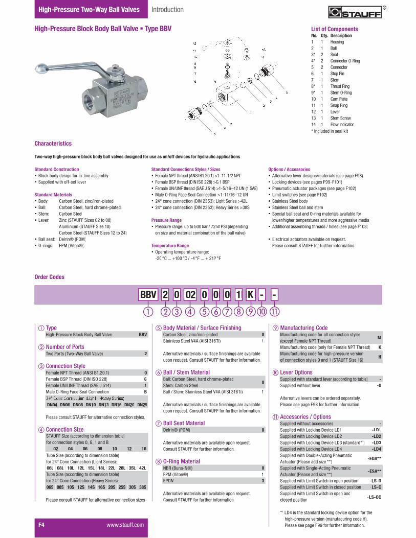
STAUFF Thread Size Nominal Dimensions (mm/in) Nom. Pressure Weight Order CodesSize d Size DN LW L I B H h m V SW K i H2 (bar/PSI) (kg/lbs) (Standard Option)
047/16–20 UNF(1/4" SAE)
66 69 40 26 47 33 13,5 11 9 115 14 82 500 0,40
BBV21040001M.23 2.70 1.57 1.02 1.84 1.29 .53 .43 .35 4.50 .55 3.23 7250 .88
069/16–18 UNF(3/8" SAE)
1010 72 43 32 52 38 17,5 11 9 115 14 87 500 0,50
BBV21060001M.39 2.82 1.68 1.25 2.04 1.49 .69 .43 .35 4.50 .55 3.43 7250 1.10
083/4–16 UNF(1/2" SAE)
1313 83 48 35 54 40 19 11 9 115 16,3 89 500 0,70
BBV21080001M.51 3.25 1.88 1.37 2.11 1.57 .74 .43 .35 4.50 .64 3.50 7250 1.54
121-1/16–12 UN(3/4" SAE)
2020 95 62 49 75 57 24,5 14 14 170 18 126 420 1,50
BBV21120001M.78 3.72 2.43 1.92 2.94 2.23 .96 .55 .55 6.69 .70 4.96 6000 3.31
161-5/16–12 UN(1" SAE)
2525 113 66 58 83 65 29,5 14 14 170 20 134 315 2,20
BBV21160001M.98 4.42 2.58 2.27 3.25 2.55 1.16 .55 .55 6.69 .78 5.28 4500 4.85
161-5/16–12 UN(1" SAE)
2525 121 74 70 88 70 34,5 14 14 170 20 139 420 2,20
BBV21160001H.98 4.76 2.91 2.76 3.46 2.76 1.36 .55 .55 6.69 .78 5.47 6000 4.85
High-Pressure Block Body Ball Valve � Type BBVFemale UN/UNF Thread (SAE J 514)
When ordering the standard option as indicated in the��<���<�������"���������;����������������<����==�����
� Body, ball and stem: Carbon Steel� Lever: Zinc (STAUFF Sizes 04 to 08)
Carbon Steel (STAUFF Sizes 12 and 16)� Ball seat: Delrin® (POM)� O-rings: FPM (Viton®)
Female UN/UNF Threade a e U /U ead(SAE J 514)
Dimensions / Order Codes
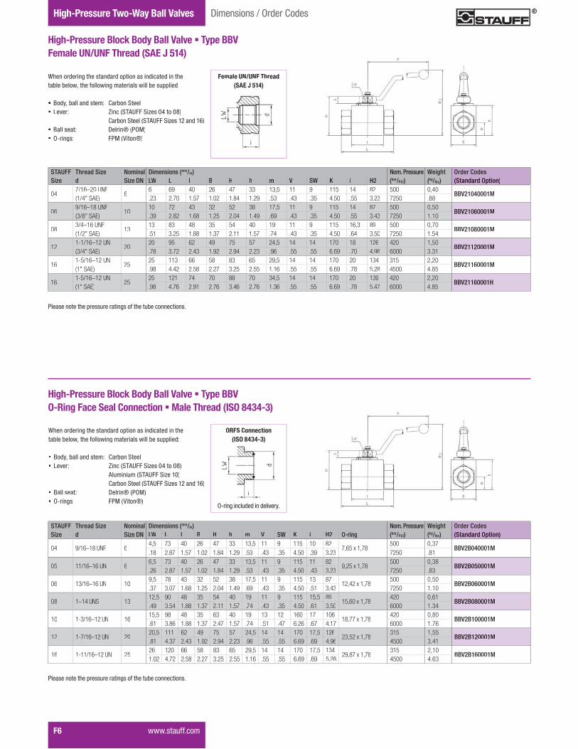
STAUFF Thread Size Nominal Dimensions (mm/in) Nom. Pressure Weight Order CodesSize d Size DN LW L I B H h m V SW K i H2 O-ring (bar/PSI) (kg/lbs) (Standard Option)
04 9/16–18 UNF 64,5 73 40 26 47 33 13,5 11 9 115 10 82
7,65 x 1,78500 0,37
BBV2B040001M.18 2.87 1.57 1.02 1.84 1.29 .53 .43 .35 4.50 .39 3.23 7250 .81
05 11/16–16 UN 86,5 73 40 26 47 33 13,5 11 9 115 11 82
9,25 x 1,78500 0,38
BBV2B050001M.26 2.87 1.57 1.02 1.84 1.29 .53 .43 .35 4.50 .43 3.23 7250 .83
06 13/16–16 UN 109,5 78 43 32 52 38 17,5 11 9 115 13 87
12,42 x 1,78500 0,50
BBV2B060001M.37 3.07 1.68 1.25 2.04 1.49 .69 .43 .35 4.50 .51 3.43 7250 1.10
08 1–14 UNS 1312,5 90 48 35 54 40 19 11 9 115 15,5 89
15,60 x 1,78420 0,61
BBV2B080001M.49 3.54 1.88 1.37 2.11 1.57 .74 .43 .35 4.50 .61 3.50 6000 1.34
10 1-3/16–12 UN 1615,5 98 48 35 63 40 19 13 12 160 17 106
18,77 x 1,78420 0,80
BBV2B100001M.61 3.86 1.88 1.37 2.47 1.57 .74 .51 .47 6.26 .67 4.17 6000 1.76
12 1-7/16–12 UN 2020,5 111 62 49 75 57 24,5 14 14 170 17,5 126
23,52 x 1,78315 1,55
BBV2B120001M.81 4.37 2.43 1.92 2.94 2.23 .96 .55 .55 6.69 .69 4.96 4500 3.41
16 1-11/16–12 UN 2526 120 66 58 83 65 29,5 14 14 170 17,5 134
29,87 x 1,78315 2,10
BBV2B160001M1.02 4.72 2.58 2.27 3.25 2.55 1.16 .55 .55 6.69 .69 5.28 4500 4.63
When ordering the standard option as indicated in the ��<���<�������"���������;����������������<����==�����
� Body, ball and stem: Carbon Steel� Lever: Zinc (STAUFF Sizes 04 to 08)
Aluminium (STAUFF Size 10)Carbon Steel (STAUFF Sizes 12 and 16)
� Ball seat: Delrin® (POM)� O-rings: FPM (Viton®)
High-Pressure Block Body Ball Valve � Type BBVO-Ring Face Seal Connection � Male Thread (ISO 8434-3)
j����;���������������������j � � � � � � � ��
ORFS Connection(ISO 8434-3)( )
�������������"��=�������������;�����"����<������������
�������������"��=�������������;�����"����<������������

Valv
esF
High-Pressure Two-Way Ball Valves
����������� F7
Dimensions / Order Codes
STAUFF Tube/Thread Size Nominal Dimensions (mm/in) Nom. Pressure Weight Order CodesSize d Size DN LW L I B H h m V SW K i H2 (bar/PSI) (kg/lbs) (Standard Option)
02 06L / M12 x 1,5 46 5 67 40 26 47 33 13,5 11 9 115 10 82 500 0,36
BBV2DN0406L0001M.24 .20 2.64 1.57 1.02 1.85 1.30 .53 .43 .35 4.53 .39 3.23 7250 .79
04 08L / M14 x 1,5 68 6 67 40 26 47 33 13,5 11 9 115 10 82 500 0,37
BBV2DN0608L0001M.31 .24 2.64 1.57 1.02 1.85 1.30 .53 .43 .35 4.53 .39 3.23 7250 .81
05 10L / M16 x 1,5 810 8 74 40 26 47 33 13,5 11 9 115 11 82 500 0,38
BBV2DN0810L0001M.39 .31 2.91 1.57 1.02 1.85 1.30 .53 .43 .35 4.53 .43 3.23 7250 .83
06 12L / M18 x 1,5 1012 10 74 43 32 52 38 17,5 11 9 115 11 87 500 0,50
BBV2DN1012L0001M.47 .39 2.91 1.69 1.26 2.05 1.50 .69 .43 .35 4.53 .43 3.43 7250 1.10
08 15L / M22 x 1,5 1315 13 82 48 35 54 40 19 11 9 115 12 89 500 0,61
BBV2DN1315L0001M.59 .51 3.23 1.89 1.38 2.13 1.57 .75 .43 .35 4.53 .47 3.50 7250 1.34
08 18L / M26 x 1,5 1318 13 82 48 35 54 40 19 11 9 115 12 89 500 0,60
BBV2DN1318L0001M.71 .51 3.23 1.89 1.38 2.13 1.57 .75 .43 .35 4.53 .47 3.50 7250 1.32
12 22L / M30 x 2 2022 20 101 62 49 75 57 24,5 14 14 170 14 126 420 1,49
BBV2DN2022L0001M.87 .79 3.98 2.44 1.93 2.95 2.24 .96 .55 .55 6.69 .55 4.96 6000 3.33
16 28L / M36 x 2 2528 25 108 66 58 83 65 29,5 14 14 170 14 134 315 2,00
BBV2DN2528L0001M1.10 .98 4.25 2.60 2.28 3.27 2.56 1.16 .55 .55 6.69 .55 5.28 4500 4.41
High-Pressure Block Body Ball Valve � Type BBV24° Cone Connection � Light Series (DIN 2353 / ISO 8434-1)
When ordering the standard option as indicated in the��<���<�������"���������;����������������<����==�����
� Body, ball and stem: Carbon Steel� Lever: Zinc (STAUFF Sizes 02 to 08)
Carbon Steel (STAUFF Sizes 12 to 16)� Ball seat: Delrin® (POM)� O-rings: FPM (Viton®)
24° Cone ConnectionCo e Co ect o(DIN 2353 / ISO 8434-1)DIN 2353 / ISO 8434-1
High-Pressure Block Body Ball Valve � Type BBV24° Cone Connection � Heavy Series (DIN 2353 / ISO 8434-1)
When ordering the standard option as indicated in the��<���<�������"���������;����������������<����==�����
� Body, ball and stem: Carbon Steel� Lever: Zinc (STAUFF Sizes 02 to 08)� Aluminium (STAUFF Size 10)
Carbon Steel (STAUFF Sizes 12 to 16)� Ball seat: Delrin® (POM)� O-rings: FPM (Viton®)
24° Cone Connection(DDIN 2353 / ISO 8434-1)
STAUFF Tube/Thread Size Nominal Dimensions (mm/in) Nom. Pressure Weight Order CodesSize d Size DN RA LW L I B H h m V SW K i H2 (bar/PSI) (kg/lbs) (Standard Option)
02 08S / M16 x 1,5 48 5 73 40 26 47 33 13,5 11 9 115 10 82 500 0,38
BBV2DN0408S0001M.31 .20 2.87 1,57 1.02 1.85 1.30 .53 .43 .35 4.53 .39 3.23 7250 .84
04 10S / M18 x 1,5 610 6 73 40 26 47 33 13,5 11 9 115 10 82 500 0,39
BBV2DN0610S0001M.39 .24 2.87 1.57 1.02 1.85 1.30 .53 .43 .35 4.53 .39 3.23 7250 .86
05 12S / M20 x 1,5 812 8 76 40 26 47 33 13,5 11 9 115 11 82 500 0,39
BBV2DN0812S0001M.47 .31 2.99 1.57 1.02 1.85 1.30 .53 .43 .35 4.53 .43 3.23 7250 .86
06 14S / M22 x 1,5 1014 10 80 43 32 52 38 17,5 11 9 115 11 87 500 0,50
BBV2DN1014S0001M.55 .39 3.15 1.69 1.26 2.05 1.50 .69 .43 .35 4.53 .43 3.43 7250 1.10
08 16S / M24 x 1,5 1316 13 86 48 35 54 40 19 11 9 115 12 89 500 0,60
BBV2DN1316S0001M.63 .51 3.39 1.89 1.38 2.13 1.57 .75 .43 .35 4.53 .47 3.50 7250 1.32
08 20S / M30 x 2 1320 15 90 48 38 54 46 19 11 9 115 12 89 500 0,60
BBV2DN1320S0001M.79 .59 3,54 1.89 1,50 2.13 1.81 .75 .43 .35 4.53 .47 3.50 7250 1.32
10 20S / M30 x 2 1620 13 90 48 35 54 40 19 13 12 160 16 106 420 0,80
BBV2DN1620S0001M.79 .51 3,54 1.89 1.38 2.13 1,57 .75 .51 .47 6.26 .63 4.17 6000 1.76
12 25S / M36 x 2 2025 20 109 62 49 75 57 24,5 14 14 170 18 126 420 1,55
BBV2DN2025S0001M.98 .79 4.29 2.44 1.93 2.95 2.24 .96 .55 .55 6.69 .71 4.96 6000 3.41
16 30S / M42 x 2 2530 25 120 66 58 75 65 29,5 14 14 170 20 134 315 2,10
BBV2DN2530S0001M1.18 .98 4.72 2.60 2.28 2.95 2.56 1.16 .55 .55 6.69 .79 5.28 4500 4.63
]�G���������������;����;������������������������������]�G ���� ��� �����; ���;� ��� ��� ������
]�G���������������;����;������������������������������]�G ���� ��� �����; ���;� ��� ��� ������
�������������"��=�������������;�����"����<������������
�������������"��=�������������;�����"����<������������
High-Pressure Two-Way Ball Valves
F8� �����������
Introduction
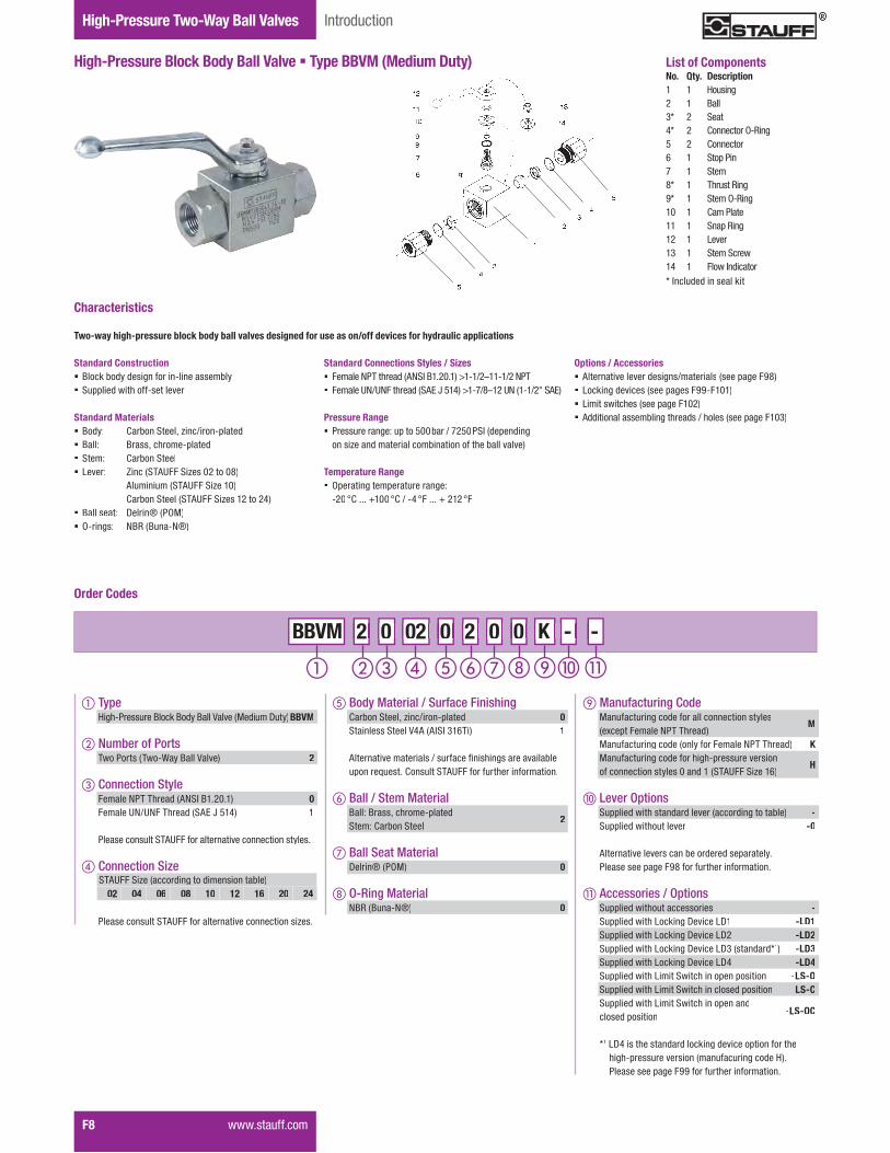
High-Pressure Block Body Ball Valve � Type BBVM (Medium Duty) List of ComponentsNo. Qty. Description1 1 Housing2 1 Ball3* 2 Seat4* 2 Connector O-Ring5 2 Connector6 1 Stop Pin7 1 Stem8* 1 Thrust Ring9* 1 Stem O-Ring10 1 Cam Plate11 1 Snap Ring12 1 Lever13 1 ���� ���14 1 �������������* Included in seal kit
K - - - K K 2 0 02 0 2 0 2 2 0 0 BBVM 02 02 0 0 2 2 0 0 0 0 -
Order Codes
� TypeHigh-Pressure Block Body Ball Valve (Medium Duty)BBVM
� Number of Ports������������������������������ 2
� Connection Style�������!����"������#! ���$�%&�$�� 0Female UN/UNF Thread (SAE J 514) 1
�������������� �#'����������������������������������
� Connection Size
�������������� �#'�����������������������������+���
� Body Material / Surface FinishingCarbon Steel, zinc/iron-plated 0Stainless Steel V4A (AISI 316Ti) 1
#���������������������.�������:���"��;������������<���=�����>������?������� �#'���������"��������������
� Ball / Stem MaterialBall: Brass, chrome-platedStem: Carbon Steel
2
� Ball Seat MaterialDelrin® (POM) 0
O-Ring MaterialNBR (Buna-N®) 0
Manufacturing Code Manufacturing code for all connection styles��G�=���������!����"�������
M
Manufacturing code (only for Female NPT Thread) KManufacturing code for high-pressure versionof connection styles 0 and 1 (STAUFF Size 16)
H
� Lever Options �==��������"�����������������������;������<��� - �==��������"��������� -0
#���������������������<������������=�������������������=�;���KQ�������"��������������
� Accessories / Options �==��������"������������� - �==��������"�W�X��;�Y�����WY$ -LD1 �==��������"�W�X��;�Y�����WY%� -LD2 �==��������"�W�X��;�Y�����WYZ����������[1) -LD3 �==��������"�W�X��;�Y�����WY\ -LD4 �==��������"�W����� ���"�����=���=������� �LS-O �==��������"�W����� ���"����������=������� �LS-C �==��������"�W����� ���"�����=������closed position -LS-OC
*1 LD4 is the standard locking device option for the"�;"�=��������������������������;�����]�������������=�;���KK�������"��������������
STAUFF Size (according to dimension table)02 04 06 08 10 12 16 20 24
Standard Connections Styles / Sizes� �������!����"������#! ���$�%&�$��_$�$.%`$$�$.%�!��� �������'!.'!���"������ #w�x�{$\��_$��.Q`$%�'!��$�$.%�� #w�
Pressure Range� Pressure range: up to 500bar / 7250PSI (depending
on size and material combination of the ball valve)
Temperature Range� Operating temperature range:
�%& �?������$&& �?�.��\ �� ��� � %$% ��
Two-way high-pressure block body ball valves designed for use as on/off devices for hydraulic applications
Characteristics
Options / Accessories� Alternative lever designs/materials (see page F98)� Locking devices (see pages F99-F101)� W���������"��������=�;���$&%�� Additional assembling threads / holes (see page F103)
Standard Construction� Block body design for in-line assembly� �==��������"������������
Standard Materials� Body: Carbon Steel, zinc/iron-plated� Ball: Brass, chrome-plated� Stem: Carbon Steel� Lever: Zinc (STAUFF Sizes 02 to 08)
Aluminium (STAUFF Size 10)Carbon Steel (STAUFF Sizes 12 to 24)
� Ball seat: Delrin® (POM)� O-rings: NBR (Buna-N®)

Valv
esF
High-Pressure Two-Way Ball Valves
����������� F9
Dimensions / Order Codes
STAUFF Thread Size Nominal Dimensions (mm/in) Nom. Pressure Weight Order CodesSize d Size DN LW L I B H h m V SW K i H2 (bar/PSI) (kg/lbs) (Standard Option)
02 1/8–27 NPT 45 69 40 26 47 33 13,5 11 9 115 10,5 82 500 0,30
BBVM20020200K.20 2.70 1.57 1.02 1.84 1.29 .53 .43 .35 4.50 .41 3.23 7250 .66
04 1/4–18 NPT 66 69 40 26 47 33 13,5 11 9 115 13,7 82 500 0,40
BBVM20040200K.23 2.70 1.57 1.02 1.84 1.29 .53 .43 .35 4.50 .54 3.23 7250 .88
06 3/8–18 NPT 1010 72 43 32 52 38 17,5 11 9 115 13,5 87 500 0,50
BBVM20060200K.39 2.82 1.68 1.25 2.04 1.49 .69 .43 .35 4.50 .53 3.43 7250 1.10
08 1/2–14 NPT 1313 83 48 35 54 40 19 11 9 115 17 89 500 0,75
BBVM20080200K.51 3.25 1.88 1.37 2.11 1.57 .74 .43 .35 4.50 .67 3.50 7250 1.65
12 3/4–14 NPT 2020 95 62 49 75 57 24,5 14 14 170 18,3 126 420 1,63
BBVM20120200K.78 3.72 2.43 1.92 2.94 2.23 .96 .55 .55 6.69 .72 4.96 6000 3.57
16 1–11-1/2 NPT 2525 113 66 58 83 65 29,5 14 14 170 21,6 134 315 2,30
BBVM20160200K.98 4.42 2.58 2.27 3.25 2.55 1.16 .55 .55 6.69 .85 5.28 4500 5.06
16 1–11-1/2 NPT 2525 113 74 70 88 70 34,5 14 14 170 20 139 420 2,20
BBVM20160200H.98 4.42 2.91 2.76 3.46 2.76 1.36 .55 .55 6.69 .78 5.47 6000 4.85
20 1-1/4–11-1/2 NPT 25/3225 120 66 58 83 65 29,5 14 14 170 22,1 134 315 2,51
BBVM20200200K.98 4.70 2.58 2.27 3.25 2.55 1.16 .55 .55 6.69 .87 5.28 4500 5.52
24 1-1/2–11-1/2 NPT 25/4025 130 66 58 83 65 29,5 14 14 170 22,1 134 250 2,70
BBVM20240200K.98 5.09 2.58 2.27 3.25 2.55 1.16 .55 .55 6.69 .87 5.28 3625 5.94
High-Pressure Block Body Ball Valve � Type BBVM (Medium Duty)Female NPT Thread (ANSI B1.20.1)
When ordering the standard option as indicated in the��<���<�������"���������;����������������<����==�����
� Body and stem: Carbon Steel� Ball: Brass� Lever: Zinc (STAUFF Sizes 02 to 08)
Carbon Steel (STAUFF Sizes 12 to 24)� Ball seat: Delrin® (POM)� O-rings: NBR (Buna-N®)
Female NPT Thread e a e ead(ANSI B1.20.1)
�������������"��=�������������;�����"����<������������
High-Pressure Block Body Ball Valve � Type BBVM (Medium Duty)Female UN/UNF Thread (SAE J 514)
When ordering the standard option as indicated in the��<���<�������"���������;����������������<����==�����
� Body and stem: Carbon Steel� Ball: Brass� Lever: Zinc (STAUFF Sizes 04 to 08)
Carbon Steel (STAUFF Sizes 12 and 16)� Ball seat: Delrin® (POM)� O-rings: NBR (Buna-N®)
Female UN/UNF ThreadFemale UN/UNF ThreadFemale UN/UNF Threademale UN/UNF Thread(SAE J 514)(SAE J 514)
STAUFF Thread Size Nominal Dimensions (mm/in) Nom. Pressure Weight Order CodesSize d Size DN LW L I B H h m V SW K i H2 (bar/PSI) (kg/lbs) (Standard Option)
047/16–20 UNF(1/4" SAE)
66 69 40 26 47 33 13,5 11 9 115 14 82 500 0,40
BBVM21040200M.23 2.70 1.57 1.02 1.84 1.29 .53 .43 .35 4.50 .55 3.23 7250 .88
069/16–18 UNF(3/8" SAE)
1010 72 43 32 52 38 17,5 11 9 115 14 87 500 0,50
BBVM21060200M.39 2.82 1.68 1.25 2.04 1.49 .69 .43 .35 4.50 .55 3.43 7250 1.10
083/4–16 UNF(1/2" SAE)
1313 83 48 35 54 40 19 11 9 115 16,3 89 500 0,70
BBVM21080200M.51 3.25 1.88 1.37 2.11 1.57 .74 .43 .35 4.50 .64 3.50 7250 1.54
121-1/16–12 UN(3/4" SAE)
2020 95 62 49 75 57 24,5 14 14 170 18 126 420 1,50
BBVM21120200M.78 3.72 2.43 1.92 2.94 2.23 .96 .55 .55 6.69 .70 4.96 6000 3.31
161-5/16–12 UN(1" SAE)
2525 113 66 58 83 65 29,5 14 14 170 20 134 315 2,20
BBVM21160200M.98 4.42 2.58 2.27 3.25 2.55 1.16 .55 .55 6.69 .78 5.28 4500 4.85
161-5/16–12 UN(1" SAE)
2525 121 74 70 88 70 34,5 14 14 170 20 139 420 2,20
BBVM21160200H.98 4.76 2.91 2.76 3.46 2.76 1.36 .55 .55 6.69 .78 5.47 6000 4.85
201-5/8–12 UN(1-1/4" SAE)
25/3225 120 66 58 83 65 29,5 14 14 170 20 134 315 2,50
BBVM21200200M.98 4.70 2.60 2.28 3.27 2.56 1.16 .55 .55 6.69 .78 5.28 4500 5.50
241-7/8–12 UN(1-1/2" SAE)
25/4025 130 66 58 83 65 29,5 14 14 170 20 134 315 2,61
BBVM21240200M.98 5.09 2.60 2.28 3.27 2.56 1.16 .55 .55 6.69 .78 5.28 4500 5.74
High-Pressure Two-Way Ball Valves
F10� �����������
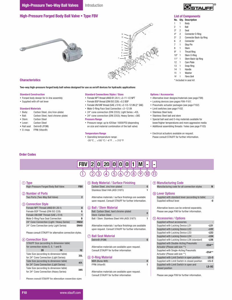
High-Pressure Forged Body Ball Valve � Type FBV
Introduction
1416
15
13
1211109
87
665
43
1
2
34
566
List of ComponentsNo. Qty. Description1 1 Body2 1 Ball3* 2 Seat4* 2 Connector O-Ring5* 2 Connector Back-Up Ring6 2 Connector7 1 Stop Pin8 1 Stem9* 1 Thrust Ring10* 1 Stem O-Ring11* 1 Stem Back-Up Ring12 1 Cam Plate13 1 Snap Ring14 1 Handle15 1 Washer16 1 Stem Bolt* Included in seal kit
M - - - M M 2 0 20 0 0 0 2 2 0 0 FBV 20 20 0 0 0 0 0 0 1 1 -
Order Codes
� TypeHigh-Pressure Forged Body Ball Valve FBV
� Number of Ports������������������������������ 2
� Connection Style�������!����"������#! ���$�%&�$�� 0Female BSP Thread (DIN ISO 228) GFemale UN/UNF Thread (SAE J 514) 1Male O-Ring Face Seal Connection B24° Cone Connection (Light / Heavy Series) DN3224° Cone Connection (only Light Series) DN40
�������������� �#'����������������������������������
� Connection Size
Tube Size (according to dimension table)for 24° Cone Connection (Light Series):
35L
Tube Size (according to dimension table)for 24° Cone Connection (Light Series):
42L
Tube Size (according to dimension table)for 24° Cone Connection (Heavy Series):
38S
�������������� �#'�����������������������������+���
Manufacturing Code MManufacturing code for all connection styles M
� Lever Options �==��������"�����������������������;������<��� - �==��������"��������� -0
#���������������������<������������=�������������������=�;���KQ�������"��������������
� Accessories / Options �==��������"������������� - �==��������"�W�X��;�Y�����WY$ -LD1 �==��������"�W�X��;�Y�����WY% -LD2 �==��������"�W�X��;�Y�����WYZ -LD3 �==��������"�W�X��;�Y�����WY\ -LD4 �==��������"�W�X��;�Y�����WY|����������� -LD6 �==��������"�Y��<���#���;���������Actuator (Please add size **)
-EDA**
�==��������"� ��;���#���;���������Actuator (Please add size **)
-ESA**
�==��������"�W����� ���"�����=���=������� �LS-O �==��������"�W����� ���"����������=������� �LS-C �==��������"�W����� ���"�����=������closed position -LS-OC
�����������=�;���KK�������"��������������
STAUFF Size (according to dimension table)for connection styles G, 0, 1 and B:
20 24 32
Standard Connections Styles / Sizes� �������!����"������#! ���$�%&�$��_%`$$�$.%�!��� �������� ���"������Y�!�� j�%%Q��_q�%�� �� �������'!.'!���"������ #w�x�{$\��_%�$.%`$%�'!��%�� #w��� }����j�~��;����� ����?���������_%`$%�'!� %\����������������Y�!�%Z{Z���W�;"�� ������_\%W�� %\����������������Y�!�%Z{Z���]����� ������_ZQ �Pressure Range� Pressure range: up to 420bar / 6000PSI (depending
on size and material combination of the ball valve)
Temperature Range� Operating temperature range:
�%& �?������$&& �?�.��\ �� ��� � %$% ��
Two-way high-pressure forged body ball valves designed for use as on/off devices for hydraulic applications
Characteristics
Options / Accessories� Alternative lever designs/materials (see page F98)� Locking devices (see pages F99-F101)� Pneumatic actuator packages (see page F102)� W���������"��������=�;���$&%�� Stainless Steel body� Stainless Steel ball and stem� Special ball seat and O-ring materials available for
�����."�;"������=�������������������;;�������������� Additional assembling threads / holes (see page F103)
� w�����������������������<��������>������������������ �#'���������"��������������
Standard Construction� Forged body design for in-line assembly� �==��������"������������
Standard Materials� Body: Carbon Steel, zinc/iron-plated� Ball: Carbon Steel, hard chrome-plated� Stem: Carbon Steel� Lever: Carbon Steel� Ball seat: Delrin® (POM)� O-rings: FPM (Viton®)
� Body Material / Surface FinishingCarbon Steel, zinc/iron-plated 0Stainless Steel V4A (AISI 316Ti) 1
#���������������������.�������:���"��;������������<���=�����>������?������� �#'���������"��������������
� Ball / Stem MaterialBall: Carbon Steel, hard chrome-platedStem: Carbon Steel
0
Ball / Stem: Stainless Steel V4A (AISI 316Ti) 1
#���������������������.�������:���"��;������������<���=�����>������?������� �#'���������"��������������
� Ball Seat MaterialDelrin® (POM) 0
#�������������������������������<����=�����>������?������� �#'���������"��������������
O-Ring MaterialNBR (Buna-N®) 0FPM (Viton®) 1
#�������������������������������<����=�����>������?������� �#'���������"��������������
Valv
esF
����������� F11
High-Pressure Two-Way Ball ValvesDimensions / Order Codes
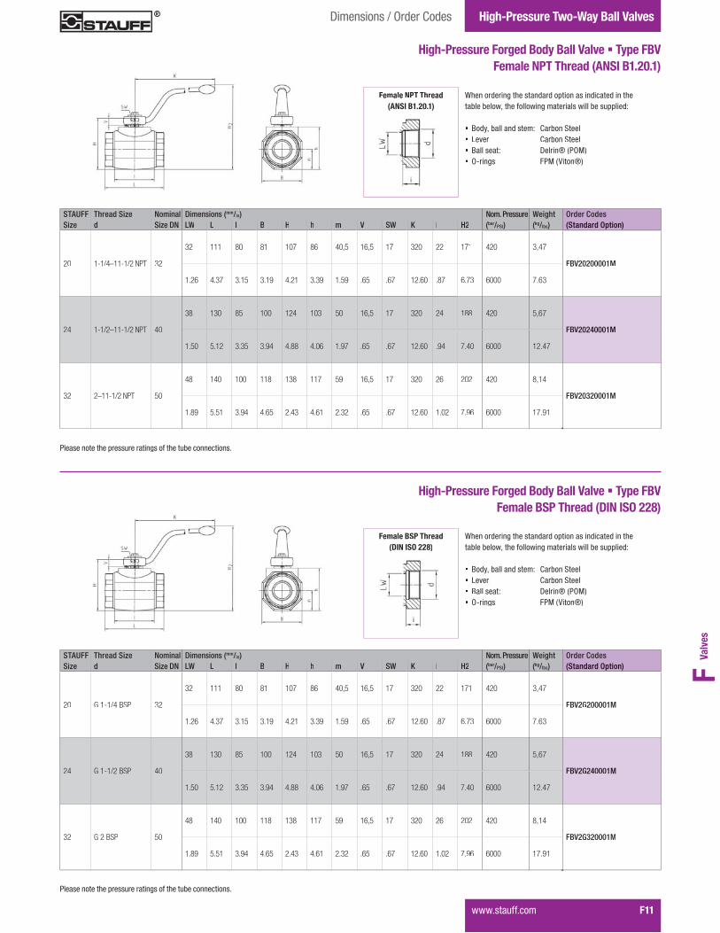
STAUFF Thread Size Nominal Dimensions (mm/in) Nom. Pressure Weight Order CodesSize d Size DN LW L I B H h m V SW K i H2 (bar/PSI) (kg/lbs) (Standard Option)
20 1-1/4–11-1/2 NPT 32
32 111 80 81 107 86 40,5 16,5 17 320 22 171 420 3,47
FBV20200001M
1.26 4.37 3.15 3.19 4.21 3.39 1.59 .65 .67 12.60 .87 6.73 6000 7.63
24 1-1/2–11-1/2 NPT 40
38 130 85 100 124 103 50 16,5 17 320 24 188 420 5,67
FBV20240001M
1.50 5.12 3.35 3.94 4.88 4.06 1.97 .65 .67 12.60 .94 7.40 6000 12.47
32 2–11-1/2 NPT 50
48 140 100 118 138 117 59 16,5 17 320 26 202 420 8,14
FBV20320001M
1.89 5.51 3.94 4.65 2.43 4.61 2.32 .65 .67 12.60 1.02 7.96 6000 17.91
High-Pressure Forged Body Ball Valve � Type FBVFemale NPT Thread (ANSI B1.20.1)
When ordering the standard option as indicated in the��<���<�������"���������;����������������<����==�����
� Body, ball and stem: Carbon Steel� Lever: Carbon Steel� Ball seat: Delrin® (POM)� O-rings: FPM (Viton®)
Female NPT Threade a e ea(ANSI B1.20.1)
�������������"��=�������������;�����"����<������������
STAUFF Thread Size Nominal Dimensions (mm/in) Nom. Pressure Weight Order CodesSize d Size DN LW L I B H h m V SW K i H2 (bar/PSI) (kg/lbs) (Standard Option)
20 G 1-1/4 BSP 32
32 111 80 81 107 86 40,5 16,5 17 320 22 171 420 3,47
FBV2G200001M
1.26 4.37 3.15 3.19 4.21 3.39 1.59 .65 .67 12.60 .87 6.73 6000 7.63
24 G 1-1/2 BSP 40
38 130 85 100 124 103 50 16,5 17 320 24 188 420 5,67
FBV2G240001M
1.50 5.12 3.35 3.94 4.88 4.06 1.97 .65 .67 12.60 .94 7.40 6000 12.47
32 G 2 BSP 50
48 140 100 118 138 117 59 16,5 17 320 26 202 420 8,14
FBV2G320001M
1.89 5.51 3.94 4.65 2.43 4.61 2.32 .65 .67 12.60 1.02 7.96 6000 17.91
High-Pressure Forged Body Ball Valve � Type FBVFemale BSP Thread (DIN ISO 228)
When ordering the standard option as indicated in the��<���<�������"���������;����������������<����==�����
� Body, ball and stem: Carbon Steel� Lever: Carbon Steel� Ball seat: Delrin® (POM)� O-rings: FPM (Viton®)
Female BSP Thread(DIN ISO 228)
�������������"��=�������������;�����"����<������������

High-Pressure Two-Way Ball Valves
F12� �����������
Dimensions / Order Codes
STAUFF Thread Size Nominal Dimensions (mm/in) Nom. Pressure Weight Order CodesSize d Size DN LW L I B H h m V SW K i H2 (bar/PSI) (kg/lbs) (Standard Option)
201-5/8–12 UN(1-1/4" SAE)
32
30 111 80 81 107 86 40,5 16,5 17 320 20 171 420 3,52
FBV21200001M
1.18 4.37 3.15 3.19 4.21 3.39 1.59 .65 .67 12.60 .79 6.73 6000 7.75
241-7/8–12 UN(1-1/2" SAE)
40
38 130 85 100 124 103 50 16,5 17 320 20 188 420 5,69
FBV21240001M
1.50 5.12 3.35 3.94 4.88 4.06 1.97 .65 .67 12.60 .79 7.40 6000 12.52
322-1/2–12 UN(2" SAE)
50
45 140 100 118 138 117 59 16,5 17 320 20 202 420 8,14
FBV21320001M
1.79 5.51 3.94 4.65 2.43 4.61 2.32 .65 .67 12.60 .79 7.96 6000 17.91
High-Pressure Forged Body Ball Valve � Type FBVFemale UN/UNF Thread (SAE J 514)
When ordering the standard option as indicated in the��<���<�������"���������;����������������<����==�����
� Body, ball and stem: Carbon Steel� Lever: Carbon Steel� Ball seat: Delrin® (POM)� O-rings: FPM (Viton®)
Female UN/UNF Thread(SAE J 514)
STAUFF Thread Size Nominal Dimensions (mm/in) Nom. Pressure Weight Order CodesSize d Size DN LW L I B H h m V SW K i H2 O-ring (bar/PSI) (kg/lbs) (Standard Option)
20 2–12 UN 32
32 139 80 81 107 86 40,5 16,5 17 320 17,5 171
37,82 x 1,78
320 3,52
FBV2B200001M
1.26 5.47 3.15 3.19 4.21 3.39 1.59 .65 .67 12.60 .69 6.73 4640 7.75
High-Pressure Forged Body Ball Valve � Type FBVO-Ring Face Seal Connection � Male Thread (ISO 8434-3)
When ordering the standard option as indicated in the��<���<�������"���������;����������������<����==�����
� Body, ball and stem: Carbon Steel� Lever: Carbon Steel� Ball seat: Delrin® (POM)� O-rings: FPM (Viton®)
ORFS Connection(ISO 8434-3) ( )
j����;���������������������j � � � � � � � ��
�������������"��=�������������;�����"����<������������
�������������"��=�������������;�����"����<������������

Valv
esF
����������� F13
High-Pressure Two-Way Ball ValvesDimensions / Order Codes
STAUFF Tube/Thread Size Nominal Dimensions (mm/in) Nom. Pressure Weight Order CodesSize d Size DN RA LW L I B H h m V SW K i H2 (bar/PSI) (kg/lbs) (Standard Option)
20 35L / M45 x 2 32
35 32 136 80 81 107 86 40,5 16,5 17 320 16 171 420 3,58
FBV2DN3235L0001M
1.38 1.26 5.35 3.15 3.19 4.21 3.39 1.59 .65 .67 12.60 .63 6.73 6000 7.88
24 42L / M52 x 2 40
42 38 147 85 100 124 103 50 16,5 17 320 16 188 420 5,54
FBV2DN4042L0001M
1.65 1.50 5.79 3.35 3.94 4.88 4.06 1.97 .65 .67 12.60 .63 7.40 6000 12.19
High-Pressure Forged Body Ball Valve � Type FBV24° Cone Connection � Light Series (DIN 2353 / ISO 8434-1)
When ordering the standard option as indicated in the��<���<�������"���������;����������������<����==�����
� Body, ball and stem: Carbon Steel� Lever: Carbon Steel� Ball seat: Delrin® (POM)� O-rings: FPM (Viton®)
STAUFF Tube/Thread Size Nominal Dimensions (mm/in) Nom. Pressure Weight Order CodesSize d Size DN RA LW L I B H h m V SW K i H2 (bar/PSI) (kg/lbs) (Standard Option)
20 38S / M52 x 2 32
38 32 148 80 81 107 86 40,5 16,5 17 320 22 171 420 3,77
FBV2DN3238S0001M
1.50 1.26 5.83 3.15 3.19 4.21 3.39 1.59 .65 .67 12.60 .87 6.73 6000 8,29
High-Pressure Forged Body Ball Valve � Type FBV24° Cone Connection � Heavy Series (DIN 2353 / ISO 8434-1)
When ordering the standard option as indicated in the��<���<�������"���������;����������������<����==�����
� Body, ball and stem: Carbon Steel� Lever: Carbon Steel� Ball seat: Delrin® (POM)� O-rings: FPM (Viton®)
24° Cone ConnectionCo e Co ect o(DIN 2353 / ISO 8434-1)DIN 2353 / ISO 8434-1
24° Cone Connection(DDIN 2353 / ISO 8434-1)
]�G���������������;����;������������������������������] � � ��� � � � � � �
]�G���������������;����;������������������������������] � � ��� � � � � � �
�������������"��=�������������;�����"����<������������
�������������"��=�������������;�����"����<������������

High-Pressure Two-Way Ball Valves
F14� �����������
Introduction
High-Pressure 800 bar / 12000 PSI Block Body Ball Valve � Type HBV List of ComponentsNo. Qty. Description1 1 Body2 1 Ball3* 2 Seat4* 2 Connector O-Ring5* 2 Pipe Back-up Ring6 2 Connector7 1 Stop Pin8 1 Stem9* 1 Thrust Ring10* 1 Stem O-Ring11* 1 Pipe Back-up12 1 Cam Plate13 1 Snap Ring14 1 Handle15 1 �������������16 1 ���� ���
6
4
10
5
13
23
54
8
14
13
12
119
15
16
7
* Included in seal kit
M - - - M M 2 0 16 0 0 0 2 2 0 0 HBV 16 16 0 0 0 0 0 0 1 1 -
Order Codes
� TypeHBV
� Number of Ports������������������������������ 2
� Connection Style�������!����"������#! ���$�%&�$�� 0
�������������� �#'����������������������������������
� Connection Size
�������������� �#'�����������������������������+���
Manufacturing Code MManufacturing code for all connection styles M
� Lever Options �==��������"�����������������������;������<��� - �==��������"��������� -0
#���������������������<������������=�������������������=�;���KQ�������"��������������
� Accessories / Options �==��������"������������� - �==��������"�W�X��;�Y�����WY$ -LD1 �==��������"�W�X��;�Y�����WY\����������� -LD4 �==��������"�Y��<���#���;���������Actuator (Please add size **)
-EDA**
�==��������"� ��;���#���;���������Actuator (Please add size **)
-ESA**
�==��������"�W����� ���"�����=���=������� �LS-O �==��������"�W����� ���"����������=������� �LS-C �==��������"�W����� ���"�����=������closed position -LS-OC
�����������=�;���KK�������"��������������
Standard Connections Styles / Sizes� �������!����"������#! ���$�%&�$��_$`$$�$.%�!��
Pressure Range� Pressure range: up to 800bar / 12000PSI (depending
on size and material combination of the ball valve)
Temperature Range� Operating temperature range:
�%& �?������$&& �?�.��\ ���������%$% ��
Two-way high-pressure block body ball valves designed for use as on/off devices for hydraulic applications (for pressures up to 800 bar / 12000 PSI)
Characteristics
Options / Accessories� Alternative lever designs/materials (see page F98)� Locking devices (see pages F99-F101)� Pneumatic actuator packages (see page F102)� W���������"��������=�;���$&%�� Stainless Steel body� Stainless Steel ball and stem� Special ball seat and O-ring materials available for
�����."�;"������=�������������������;;�������������� Additional assembling threads (see page F103)
� w�����������������������<��������>������������������ �#'���������"��������������
Standard Construction� Block body design for in-line assembly� �==��������"������
Standard Materials� Body: Carbon Steel, zinc/iron-plated� Ball: Carbon Steel, hard chrome-plated� Stem: Carbon Steel� Lever: Carbon Steel� Ball seat: Delrin® (POM)� O-rings: FPM (Viton®)
for connection styles G, 0, 1 and B:04 06 08 12 16
� Body Material / Surface FinishingCarbon Steel, zinc/iron-plated 0Stainless Steel V4A (AISI 316Ti) 1
#���������������������.�������:���"��;������������<���=�����>������?������� �#'���������"��������������
� Ball / Stem Material Ball: Carbon Steel, hard chrome-plated
Stem: Carbon Steel0
Ball / Stem: Stainless Steel V4A (AISI 316Ti) 1
#���������������������.�������:���"��;������������<���=�����>������?������� �#'���������"��������������
� Ball Seat MaterialDelrin® (POM) 0
#�������������������������������<����=�����>������?������� �#'���������"��������������
O-Ring MaterialNBR (Buna-N®) 0FPM (Viton®) 1
#�������������������������������<����=�����>������?������� �#'���������"��������������

Valv
esF
High-Pressure Two-Way Ball Valves
����������� F15
STAUFF Thread Size Nominal Dimensions (mm/in) Nom. Pressure Weight Order CodesSize d Size DN LW L I B H m V SW K i H1 H2 (bar/PSI) (kg/lbs) (Standard Option)
04 1/4–18 NPT 66 130 76 50 64 25 11 9 115 13,7 99 800 1,92
HBV20040001M.39 8.44 4.94 3.25 4.16 1.62 .71 .58 7.47 0.89 6.43 12000 4.22
06 3/8–18 NPT 1013 130 76 50 64 25 11 9 115 13,5 99 800 1,85
HBV20060001M.84 8.44 4.94 3.25 4.16 1.62 .71 .58 7.47 0.88 6.43 12000 4.07
08 1/2–14 NPT 1313 130 76 50 64 25 11 9 115 17 99 800 1,79
HBV20080001M.84 8.44 4.94 3.25 4.16 1.62 .71 .58 7.47 1.10 6.43 12000 3.93
12 3/4–14 NPT 2020 161 111 90 108 45 14 14 200 18,3 112 800 7,83
HBV20120001M1.30 10.45 7.21 5.84 7.01 2.92 .91 .91 12.99 1.19 7.27 12000 17.23
16 1–11-1/2 NPT 2525 164 111 90 108 45 14 14 200 21,6 112 800 7,68
HBV20160001M1.62 10.65 7.21 5.84 7.01 2.92 .91 .91 12.99 1.40 7.27 12000 16.90
High-Pressure 800 bar / 12000 PSI Block Body Ball Valve � Type HBVFemale NPT Thread (ANSI B1.20.1)
When ordering the standard option as indicated in the��<���<�������"���������;����������������<����==�����
� Body, ball and stem: Carbon Steel� Lever: Zinc� Ball seat: Delrin® (POM)� O-rings: FPM (Viton®)
Dimensions / Order Codes
Female NPT Threade a e ea(ANSI B1.20.1)
�������������"��=�������������;�����"����<������������
Two-Way Ball Valves
F16� �����������
IntroductionHigh-Pressure Two-Way Ball Valves
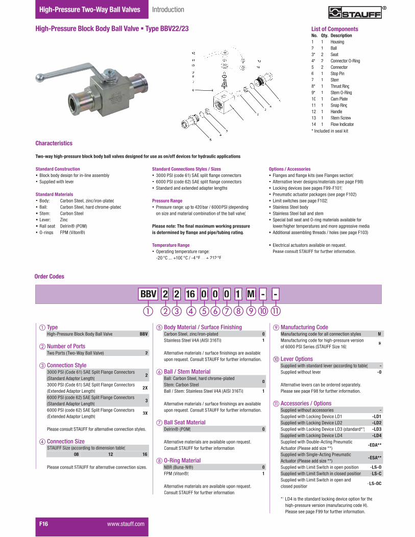
High-Pressure Block Body Ball Valve � Type BBV22/23 List of ComponentsNo. Qty. Description1 1 Housing2 1 Ball3* 2 Seat4* 2 Connector O-Ring5 2 Connector6 1 Stop Pin7 1 Stem8* 1 Thrust Ring9* 1 Stem O-Ring10 1 Cam Plate11 1 Snap Ring12 1 Handle13 1 ���� ���14 1 �������������* Included in seal kit
Order Codes
� TypeHigh-Pressure Block Body Ball Valve BBV
� Number of Ports������������������������������ 2
� Connection Style3000 PSI (Code 61) SAE Split Flange Connectors(Standard Adaptor Length)
2
3000 PSI (Code 61) SAE Split Flange Connectors�wG�������#��=����W��;�"�
2X
6000 PSI (code 62) SAE Split Flange Connectors(Standard Adaptor Length)
3
6000 PSI (code 62) SAE Split Flange Connectors�wG�������#��=����W��;�"�
3X
�������������� �#'����������������������������������
� Connection Size
�������������� �#'�����������������������������+���
Manufacturing Code MManufacturing code for all connection styles MManufacturing code for high-pressure version of 6000 PSI Series (STAUFF Size 16)
H
� Lever Options �==��������"�����������������������;������<��� - �==��������"��������� -0
#���������������������<������������=�������������������=�;���KQ�������"��������������
� Accessories / Options �==��������"������������� - �==��������"�W�X��;�Y�����WY$ -LD1 �==��������"�W�X��;�Y�����WY% -LD2 �==��������"�W�X��;�Y�����WYZ����������[1) -LD3 �==��������"�W�X��;�Y�����WY\ -LD4 �==��������"�Y��<���#���;���������Actuator (Please add size **)
-EDA**
�==��������"� ��;���#���;���������Actuator (Please add size **)
-ESA**
�==��������"�W����� ���"�����=���=������� �LS-O �==��������"�W����� ���"����������=������� �LS-C �==��������"�W����� ���"�����=������closed position -LS-OC
*1 LD4 is the standard locking device option for the "�;"�=��������������������������;�����]�������������=�;���KK�������"��������������
Standard Connections Styles / Sizes� Z&&&�� �������|$�� #w��=�������;����������� |&&&�� �������|%�� #w��=�������;����������� �������������G����������=�������;�"�
Pressure Range� Pressure range: up to 420bar / 6000PSI (depending
on size and material combination of the ball valve)
������������ ��������������������������������������������������������������������������
Temperature Range� Operating temperature range:
�%& �?������$&& �?�.��\ �� ��� � %$% ��
Two-way high-pressure block body ball valves designed for use as on/off devices for hydraulic applications
Characteristics
Options / Accessories� ����;����������;��X�������������;����������� Alternative lever designs/materials (see page F98)� Locking devices (see pages F99-F101)� Pneumatic actuator packages (see page F102)� W���������"��������=�;���$&%�� Stainless Steel body� Stainless Steel ball and stem� Special ball seat and O-ring materials available for
�����."�;"������=�������������������;;�������������� Additional assembling threads / holes (see page F103)
� w�����������������������<��������>������������������ �#'���������"��������������
Standard Construction� Block body design for in-line assembly� �==��������"������
Standard Materials� Body: Carbon Steel, zinc/iron-plated� Ball: Carbon Steel, hard chrome-plated� Stem: Carbon Steel� Lever: Zinc� Ball seat: Delrin® (POM)� O-rings: FPM (Viton®)
2 2 16 0 0 0 1 M - - - M M 2 2 2 2 BBV 16 16 0 0 0 0 0 0 1 1 -
STAUFF Size (according to dimension table)08 12 16
� Body Material / Surface FinishingCarbon Steel, zinc/iron-plated 0Stainless Steel V4A (AISI 316Ti) 1
#���������������������.�������:���"��;������������<���=�����>������?������� �#'���������"��������������
� Ball / Stem MaterialBall: Carbon Steel, hard chrome-platedStem: Carbon Steel
0
Ball / Stem: Stainless Steel V4A (AISI 316Ti) 1
#���������������������.�������:���"��;������������<���=�����>������?������� �#'���������"��������������
� Ball Seat MaterialDelrin® (POM) 0
#�������������������������������<����=�����>������?������� �#'���������"��������������
O-Ring MaterialNBR (Buna-N®) 0FPM (Viton®) 1
#�������������������������������<����=�����>������?������� �#'���������"��������������

Valv
esF
Two-Way Ball ValvesDimensions / Order Codes High-Pressure Two-Way Ball Valves
High-Pressure Block Body Ball Valve � Type BBV22/233000 PSI SAE Split Flange Connection (ISO 6162-1)
��<���<�������"���������;����������������<����==�����
� Body, ball and stem: Carbon Steel� Lever: Zinc� Ball seat: Delrin® (POM)� O-rings: FPM (Viton®)
STAUFF SAE Nominal Dimensions (mm/in) Nom. Pressure Weight Order CodesSize Flange Size Size DN LW L I B H h m V SW K d1 D2 t3 H1 H2 (bar/PSI) (kg/lbs) (Standard Option)
08 1/2 1313 151 48 35 54 40 19 11 9 115 25,5 30,2 6,8 89 345 0,85
BBV22080001M.51 5.94 1.89 1.38 2.13 1.57 .75 .43 .35 4.53 1.00 1.19 .27 3.50 5000 1.87
12 3/4 2019 162 62 49 75 57 24,5 14 14 200 31,9 38,1 6,8 79 345 1,87
BBV22120001M.75 6.38 2.44 1.93 2.95 2.24 .96 .55 .55 7.87 1.26 1.50 .27 3.11 5000 4.11
16 1 2525 178 66 58 83 65 29,5 14 14 200 39,8 44,4 8,1 87 345 2,70
BBV22160001M.98 7.01 2.60 2.28 3.27 2.56 1.16 .55 .55 7.87 1.57 1.75 .32 3.43 5000 5.94
3000 PSI Series (Code 61) � Standard Adaptor Length
STAUFF SAE Nominal Dimensions (mm/in) Nom. Pressure Weight Order CodesSize Flange Size Size DN LW L I B H h m V SW K d1 D2 t3 H1 H2 (bar/PSI) (kg/lbs) (Standard Option)
08 1/2 1313 170 48 35 54 40 19 11 9 115 25,5 30,2 6,8 89 345 0,89
BBV22X080001M.51 6.69 1.89 1.38 2.13 1.57 .75 .43 .35 4.53 1.00 1.19 .27 3.50 5000 1.96
12 3/4 2019 200 62 49 75 57 24,5 14 14 200 31,9 38,1 6,8 79 345 2,00
BBV22X120001M.75 7.87 2.44 1.93 2.95 2.24 .96 .55 .55 7.87 1.26 1.50 .27 3.11 5000 4.40
16 1 2525 215 66 58 83 65 29,5 14 14 200 39,8 44,4 8,1 87 345 2,85
BBV22X160001M.98 8.46 2.60 2.28 3.27 2.56 1.16 .55 .55 7.87 1.57 1.75 .32 3.43 5000 6.27
3000 PSI Series (Code 61) � Extended Adaptor Length
High-Pressure Block Body Ball Valve � Type BBV22/236000 PSI SAE Split Flange Connection (ISO 6162-2)
When ordering the standard option as indicated in the��<���<�������"���������;����������������<����==�����
� Body, ball and stem: Carbon Steel� Lever: Zinc� Ball seat: Delrin® (POM)� O-rings: FPM (Viton®)
STAUFF SAE Nominal Dimensions (mm/in) Nom. Pressure Weight Order CodesSize Flange Size Size DN LW L I B H h m V SW K d1 D2 t3 H1 H2 (bar/PSI) (kg/lbs) (Standard Option)
08 1/2 1313 151 48 35 54 40 19 11 9 115 25,5 31,8 7,9 89 420 0,90 BBV23080001M.51 5.94 1.89 1.38 2.13 1.57 .75 .43 .35 4.53 1.00 1.25 .33 3.50 6000 1.98
12 3/4 2019 174 62 49 75 57 24,5 14 14 200 31,9 41,3 8,9 79 420 1,95 BBV23120001M.75 6.85 2.44 1.93 2.95 2.24 .96 .55 .55 7.87 1.26 1.63 .38 3.11 6000 4.29
16 1 2525 198 66 58 83 65 29,5 14 14 200 39,8 47,6 9,6 87 315 3,00 BBV23160001M.98 7.80 2.60 2.28 3.27 2.56 1.16 .55 .55 7.87 1.7 1.87 3.78 3.43 4500 6.60
16 1 2525 206 74 70 88 70 34,5 14 14 200 39,8 47,6 6,9 92 420 3,00 BBV23160001H.98 8.11 2.91 2.76 3.46 2.76 1.36 .55 .55 7.87 1.7 1.87 3.78 3.43 6000 6.60
6000 PSI Series (Code 62) � Standard Adaptor Length
STAUFF SAE Nominal Dimensions (mm/in) Nom. Pressure Weight Order CodesSize Flange Size Size DN LW L I B H h m V SW K d1 D2 t3 H1 H2 (bar/PSI) (kg/lbs) (Standard Option)
08 1/2 1313 180 48 35 54 40 19 11 9 115 25,5 31,8 7,9 89 420 1,00
BBV23X080001M.51 7.09 1.89 1.38 2.13 1.57 .75 .43 .35 4.53 1.00 1.25 .33 3.50 6000 2.20
12 3/4 2019 200 62 49 75 57 24,5 14 14 200 31,9 41,3 8,9 79 420 2,10
BBV23X120001M.75 7.87 2.44 1.93 2.95 2.24 .96 .55 .55 7.87 1.26 1.63 .38 3.11 6000 4.62
16 1 2525 250 66 58 83 65 29,5 14 14 200 39,8 47,6 9,6 87 315 3,15
BBV23X160001M.98 9.84 2.60 2.28 3.27 2.56 1.16 .55 .55 7.87 1.7 1.87 3.78 3.43 4500 6.93
16 1 2525 250 74 70 88 70 34,5 14 14 200 39,8 47,6 6,9 92 420 3,15
BBV23X160001H.98 9.84 2.91 2.76 3.46 2.76 1.36 .55 .55 7.87 1.7 1.87 3.78 3.43 6000 6.93
6000 PSI Series (Code 62) � Extended Adaptor Length
������������ ��������������������������������������������������������������������������
������������ ��������������������������������������������������������������������������
����������� F17

Two-Way Ball Valves IntroductionHigh-Pressure Two-Way Ball Valves
F18� �����������
High-Pressure Forged Body Ball Valve � Type FBV22/23 List of ComponentsNo. Qty. Description1 1 Body2 1 Ball3* 2 Seat4* 2 Connector O-Ring5* 2 Connector Back-Up Ring6 2 Connector7 1 Stop Pin8 1 Stem9* 1 Thrust Ring10* 1 Stem O-Ring11* 1 Stem Back-Up Ring12 1 Cam Plate13 1 Snap Ring14 1 Handle15 1 Washer16 1 Stem Bolt* Included in seal kit
1416
15
13
1211109
8
7
665
43
1
2
34
56
Order Codes
� TypeHigh-Pressure Forged Body Ball Valve FBV
� Number of Ports������������������������������ 2
� Connection Style3000 PSI (Code 61) SAE Split Flange Connectors(Standard Adaptor Length)
2
3000 PSI (Code 61) SAE Split Flange Connectors�wG�������#��=����W��;�"�
2X
6000 PSI (code 62) SAE Split Flange Connectors(Standard Adaptor Length)
3
6000 PSI (code 62) SAE Split Flange Connectors�wG�������#��=����W��;�"�
3X
�������������� �#'����������������������������������
� Connection Size
�������������� �#'�����������������������������+���
Standard Connections Styles / Sizes� Z&&&�� �������|$�� #w��=�������;����������� |&&&�� �������|%�� #w��=�������;����������� �������������G����������=�������;�"�
Pressure Range� Pressure range: up to 420bar / 6000PSI (depending
on size and material combination of the ball valve)
������������ �������������������������������������������������������������������������
Temperature Range� Operating temperature range:
�%& �?������$&& �?�.��\ �� ��� � %$% ��
Two-way high-pressure forged body ball valves designed for use as on/off devices for hydraulic applications
Characteristics
Options / Accessories� ����;����������;��X�������������;����������� Alternative lever designs/materials (see page F98)� Locking devices (see pages F99-F101)� Pneumatic actuator packages (see page F102)� W���������"��������=�;���$&%�� Stainless Steel body� Stainless Steel ball and stem� Special ball seat and O-ring materials available for
�����."�;"������=�������������������;;�������������� Additional assembling threads (see page F103)
� w�����������������������<��������>������������������ �#'���������"��������������
Standard Construction� Forged body design for in-line assembly� �==��������"������;"�������
Standard Materials� Body: Carbon Steel, zinc/iron-plated� Ball: Carbon Steel, hard chrome-plated� Stem: Carbon Steel� Lever: Carbon Steel� Ball seat: Delrin® (POM)� O-rings: FPM (Viton®)
STAUFF Size (according to dimension table)20 24 32
M - - - M M 2 2 20 0 0 0 2 2 2 2 FBV 20 20 0 0 0 0 0 0 1 1 -
Manufacturing Code Manufacturing code for all connection styles M
� Lever Options �==��������"�����������������������;������<��� - �==��������"��������� -0
#���������������������<������������=�������������������=�;���KQ�������"��������������
� Accessories / Options �==��������"������������� - �==��������"�W�X��;�Y�����WY$ -LD1 �==��������"�W�X��;�Y�����WY% -LD2 �==��������"�W�X��;�Y�����WY|����������� -LD6 �==��������"�Y��<���#���;���������Actuator (Please add size **)
-EDA**
�==��������"� ��;���#���;���������Actuator (Please add size **)
-ESA**
�==��������"�W����� ���"�����=���=������� �LS-O �==��������"�W����� ���"����������=������� �LS-C �==��������"�W����� ���"�����=������closed position -LS-OC
�����������=�;���KK�������"��������������
� Body Material / Surface FinishingCarbon Steel, zinc/iron-plated 0Stainless Steel V4A (AISI 316Ti) 1
#���������������������.�������:���"��;������������<���=�����>������?������� �#'���������"��������������
� Ball / Stem MaterialBall: Carbon Steel, hard chrome-platedStem: Carbon Steel
0
Ball / Stem: Stainless Steel V4A (AISI 316Ti) 1
#���������������������.�������:���"��;������������<���=�����>������?������� �#'���������"��������������
� Ball Seat MaterialDelrin® (POM) 0
#�������������������������������<����=�����>������?������� �#'���������"��������������
O-Ring MaterialNBR (Buna-N®) 0FPM (Viton®) 1
#�������������������������������<����=�����>������?������� �#'���������"��������������
Valv
esF
Two-Way Ball ValvesDimensions / Order Codes High-Pressure Two-Way Ball Valves
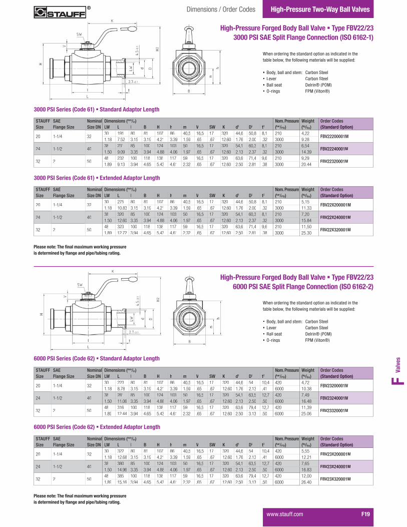
����������� F19
High-Pressure Forged Body Ball Valve � Type FBV22/233000 PSI SAE Split Flange Connection (ISO 6162-1)
When ordering the standard option as indicated in the��<���<�������"���������;����������������<����==�����
� Body, ball and stem: Carbon Steel� Lever: Carbon Steel � Ball seat: Delrin® (POM)� O-rings: FPM (Viton®)
STAUFF SAE Nominal Dimensions (mm/in) Nom. Pressure Weight Order CodesSize Flange Size Size DN LW L I B H h m V SW K d1 D2 t3 (bar/PSI) (kg/lbs) (Standard Option)
20 1-1/4 3230 191 80 81 107 86 40,5 16,5 17 320 44,6 50,8 8,1 210 4,22
FBV22200001M1.18 7.52 3.15 3.19 4.21 3.39 1.59 .65 .67 12.60 1.76 2.00 .32 3000 9.28
24 1-1/2 4038 231 85 100 124 103 50 16,5 17 320 54,1 60,3 8,1 210 6,54
FBV22240001M1.50 9.09 3.35 3.94 4.88 4.06 1.97 .65 .67 12.60 2.13 2.37 .32 3000 14.39
32 2 5048 232 100 118 138 117 59 16,5 17 320 63,6 71,4 9,6 210 9,29
FBV22320001M1.89 9.13 3.94 4.65 5.43 4.61 2.32 .65 .67 12.60 2.50 2.81 .38 3000 20.44
STAUFF SAE Nominal Dimensions (mm/in) Nom. Pressure Weight Order CodesSize Flange Size Size DN LW L I B H h m V SW K d1 D2 t3 (bar/PSI) (kg/lbs) (Standard Option)
20 1-1/4 3230 275 80 81 107 86 40,5 16,5 17 320 44,6 50,8 8,1 210 5,15
FBV22X200001M1.18 10.83 3.15 3.19 4.21 3.39 1.59 .65 .67 12.60 1.76 2.00 .32 3000 11.33
24 1-1/2 4038 320 85 100 124 103 50 16,5 17 320 54,1 60,3 8,1 210 7,20
FBV22X240001M1.50 12.60 3.35 3.94 4.88 4.06 1.97 .65 .67 12.60 2.13 2.37 .32 3000 15.84
32 2 5048 323 100 118 138 117 59 16,5 17 320 63,6 71,4 9,6 210 11,50
FBV22X320001M1.89 12.72 3.94 4.65 5.43 4.61 2.32 .65 .67 12.60 2.50 2.81 .38 3000 25.30
High-Pressure Forged Body Ball Valve � Type FBV22/236000 PSI SAE Split Flange Connection (ISO 6162-2)
When ordering the standard option as indicated in the��<���<�������"���������;����������������<����==�����
� Body, ball and stem: Carbon Steel� Lever: Carbon Steel � Ball seat: Delrin® (POM)� O-rings: FPM (Viton®)
STAUFF SAE Nominal Dimensions (mm/in) Nom. Pressure Weight Order CodesSize Flange Size Size DN LW L I B H h m V SW K d1 D2 t3 (bar/PSI) (kg/lbs) (Standard Option)
20 1-1/4 3230 223 80 81 107 86 40,5 16,5 17 320 44,6 54 10,4 420 4,72
FBV23200001M1.18 8.78 3.15 3.19 4.21 3.39 1.59 .65 .67 12.60 1.76 2.13 .41 6000 10.38
24 1-1/2 4038 281 85 100 124 103 50 16,5 17 320 54,1 63,5 12,7 420 7,49
FBV23240001M1.50 11.06 3.35 3.94 4.88 4.06 1.97 .65 .67 12.60 2.13 2.50 .50 6000 16.48
32 2 5048 316 100 118 138 117 59 16,5 17 320 63,6 79,4 12,7 420 11,39
FBV23320001M1.89 12.44 3.94 4.65 5.43 4.61 2.32 .65 .67 12.60 2.50 3.13 .50 6000 25.06
STAUFF SAE Nominal Dimensions (mm/in) Nom. Pressure Weight Order CodesSize Flange Size Size DN LW L I B H h m V SW K d1 D2 t3 (bar/PSI) (kg/lbs) (Standard Option)
20 1-1/4 3230 322 80 81 107 86 40,5 16,5 17 320 44,6 54 10,4 420 5,55
FBV23X200001M1.18 12.68 3.15 3.19 4.21 3.39 1.59 .65 .67 12.60 1.76 2.13 .41 6000 12.21
24 1-1/2 4038 380 85 100 124 103 50 16,5 17 320 54,1 63,5 12,7 420 7,65
FBV23X240001M1.50 14.96 3.35 3.94 4.88 4.06 1.97 .65 .67 12.60 2.13 2.50 .50 6000 16.83
32 2 5048 385 100 118 138 117 59 16,5 17 320 63,6 79,4 12,7 420 12,00
FBV23X320001M1.89 15.16 3.94 4.65 5.43 4.61 2.32 .65 .67 12.60 2.50 3.13 .50 6000 26.40
������������ ��������������������������������������������������������������������������
������������ ��������������������������������������������������������������������������
3000 PSI Series (Code 61) � Standard Adaptor Length
3000 PSI Series (Code 61) � Extended Adaptor Length
6000 PSI Series (Code 62) � Standard Adaptor Length
6000 PSI Series (Code 62) � Extended Adaptor Length
Two-Way Ball Valves IntroductionHigh-Pressure Two-Way Ball Valves
F20� �����������
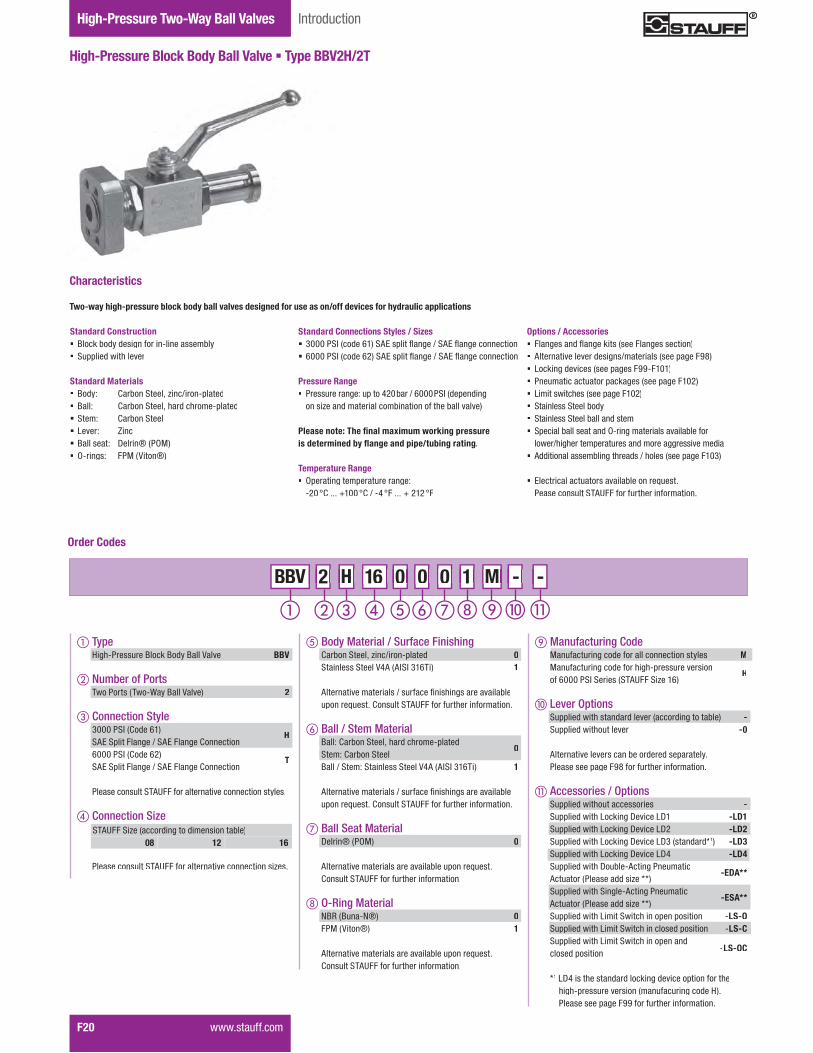
High-Pressure Block Body Ball Valve � Type BBV2H/2T
Standard Connections Styles / Sizes � Z&&&�� �������|$�� #w��=��������;��.� #w�����;���������� � |&&&�� �������|%�� #w��=��������;��.� #w�����;����������
Pressure Range� Pressure range: up to 420 bar / 6000 PSI (depending
on size and material combination of the ball valve)
������������ ���������������������������������������������������������������������������
Temperature Range� Operating temperature range:
�%&��?������$&&��?�.��\����������%$%���
Two-way high-pressure block body ball valves designed for use as on/off devices for hydraulic applications
Characteristics
Options / Accessories� ����;�����������;��X�������������;����������� Alternative lever designs/materials (see page F98)� Locking devices (see pages F99-F101)� Pneumatic actuator packages (see page F102)� W���������"��������=�;���$&%�� Stainless Steel body� Stainless Steel ball and stem� Special ball seat and O-ring materials available for
�����."�;"������=�������������������;;�������������� Additional assembling threads / holes (see page F103)
� w�����������������������<��������>������������������ �#'���������"��������������
Standard Construction� Block body design for in-line assembly� �==��������"������
Standard Materials� Body: Carbon Steel, zinc/iron-plated� Ball: Carbon Steel, hard chrome-plated� Stem: Carbon Steel� Lever: Zinc� Ball seat: Delrin® (POM)� O-rings: FPM (Viton®)
Order Codes
� Type High-Pressure Block Body Ball Valve BBV
� Number of Ports� �������������������������������� 2
� Connection Style 3000 PSI (Code 61) SAE Split Flange / SAE Flange Connection
H
6000 PSI (Code 62) SAE Split Flange / SAE Flange Connection
T
� �������������� �#'����������������������������������
� Connection Size
� �������������� �#'�����������������������������+���
M - - - M M 2 H 16 0 0 0 2 2 H H BBV 16 16 0 0 0 0 0 0 1 1 -
STAUFF Size (according to dimension table)08 12 16
� Body Material / Surface Finishing Carbon Steel, zinc/iron-plated 0 Stainless Steel V4A (AISI 316Ti) 1
� #���������������������.�������:����"��;������������<��� �=�����>������?������� �#'���������"��������������
� Ball / Stem Material Ball: Carbon Steel, hard chrome-plated Stem: Carbon Steel
0
Ball / Stem: Stainless Steel V4A (AISI 316Ti) 1
� #���������������������.�������:����"��;������������<��� �=�����>������?������� �#'���������"��������������
� Ball Seat Material Delrin® (POM) 0
� #�������������������������������<����=�����>������� ?������� �#'���������"��������������
O-Ring Material NBR (Buna-N®) 0 FPM (Viton®) 1
� #�������������������������������<����=�����>������� ?������� �#'���������"��������������
Manufacturing Code MManufacturing code for all connection styles M Manufacturing code for high-pressure version of 6000 PSI Series (STAUFF Size 16)
H
� Lever Options� �==��������"�����������������������;������<��� -� �==��������"���������� -0
� #���������������������<������������=��������� �����������=�;���KQ�������"��������������
� Accessories / Options� �==��������"�������������� -� �==��������"�W�X��;�Y�����WY$� -LD1� �==��������"�W�X��;�Y�����WY%� -LD2� �==��������"�W�X��;�Y�����WYZ����������[1) -LD3� �==��������"�W�X��;�Y�����WY\� -LD4� �==��������"�Y��<���#���;��������� Actuator (Please add size **)
-EDA**
� �==��������"� ��;���#���;��������� Actuator (Please add size **)
-ESA**
� �==��������"�W����� ���"�����=���=�������� �LS-O� �==��������"�W����� ���"����������=�������� �LS-C� �==��������"�W����� ���"�����=������ closed position -LS-OC
*1 LD4 is the standard locking device option for the "�;"�=��������������������������;�����]�������������=�;���KK�������"��������������

Valv
esF
Two-Way Ball ValvesDimensions / Order Codes High-Pressure Two-Way Ball Valves
����������� F21
High-Pressure Block Body Ball Valve � Type BBV2H/2T3000 PSI SAE Split Flange / SAE Flange Connection (ISO 6162-1)
When ordering the standard option as indicated in the��<���<�������"���������;����������������<����==�����
� Body, ball and stem: Carbon Steel� Lever: Zinc� Ball seat: Delrin® (POM)� O-rings: FPM (Viton®)
STAUFF SAE Nominal Dimensions (mm/in) K tap Nom. Pressure Weight Order CodesSize Flange Size Size DN A C F G H J UN-2B (bar/PSI) (kg/lbs) (Standard Option)
08 1/2 13136 13 115 99 17,5 38,1
5/16–18210 1,20
BBV2H080001M5.35 .51 4.53 3.90 .69 1.50 3000 2.60
12 3/4 20149 19 170 136 22,2 47,6
3/8–16210 2,50
BBV2H120001M5.87 .75 6.69 5.35 .87 1.87 3000 5.50
16 1 25163 25 170 141 26,2 52,4
3/8–16210 3,50
BBV2H160001M6.42 .98 6.69 5.55 1.03 2.06 3000 7.70
3000 PSI Series (Code 61)
STAUFF SAE Nominal Dimensions (mm/in) K tap Nom. Pressure Weight Order CodesSize Flange Size Size DN A C F G H J UN-2B (bar/PSI) (kg/lbs) (Standard Option)
08 1/2 13136 13 115 99 18,2 40,5
5/16–18420 1,20
BBV2T080001M5.35 .51 4.53 3.90 .72 1.59 6000 2.60
12 3/4 20155 19 170 138 23,8 50,8
3/8–16420 2,50
BBV2T120001M6.10 .75 6.69 5.43 .94 2.00 6000 5.50
16 1 25173 25 170 146 27,8 57,2
7/16–14420 3,50
BBV2T160001H6.81 .98 6.69 5.75 1.09 2.25 6000 7.70
G
H
J
K
F
A
C
High-Pressure Block Body Ball Valve � Type BBV2H/2T6000 PSI SAE Split Flange / SAE Flange Connection (ISO 6162-2)
H
J
K
F
A
C
6000 PSI Series (Code 62)
When ordering the standard option as indicated in the��<���<�������"���������;����������������<����==�����
� Body, ball and stem: Carbon Steel� Lever: Zinc� Ball seat: Delrin® (POM)� O-rings: FPM (Viton®)

Two-Way Ball Valves IntroductionHigh-Pressure Two-Way Ball Valves
F22� �����������
High-Pressure Block Body Ball Valve � Type BBV
� TypeHigh-Pressure Block Body Ball Valve BBV
� Number of Ports������������������������������ 2
� Connection Style3000 PSI (Code 61) SAE Mating Flange ?������������"�}������ j��"�����
EM
3000 PSI (Code 61) SAE Mating Flange ?������������"�'��:���?�������'!?���"�����
E
6000 PSI (Code 62) SAE Mating Flange ?������������"�}������ j��"�����
SM
6000 PSI (Code 62) SAE Mating Flange ?������������"�'��:���?�������'!?���"�����
S
�������������� �#'����������������������������������
� Connection Size
�������������� �#'�����������������������������+���
Standard Connections Styles / Sizes� Z&&&�� �������|$�� #w������;����;����������� |&&&�� �������|%�� #w������;����;����������� }������ j��������:����������'!?���"������
Pressure Range� Pressure range: up to 420bar / 6000PSI (depending
on size and material combination of the ball valve)
������������ �������������������������������������������������������������������������
Temperature Range� Operating temperature range:
�%& �?������$&& �?�.��\ �� ��� � %$% ��
Two-way high-pressure block body ball valves designed for use as on/off devices for hydraulic applications
Characteristics
Options / Accessories� ����;����������;��X�������������;����������� Alternative lever designs/materials (see page F98)� Locking devices (see pages F99-F101)� Pneumatic actuator packages (see page F102)� W���������"��������=�;���$&%�� Stainless Steel body� Stainless Steel ball and stem� Special ball seat and O-ring materials available for
�����."�;"������=�������������������;;�������������� Additional assembling threads / holes (see page F103)
� w�����������������������<��������>������������������ �#'���������"��������������
Standard Construction� Block body design for in-line assembly� �==��������"������������
Standard Materials� Body: Carbon Steel, zinc/iron-plated� Ball: Carbon Steel, hard chrome-plated� Stem: Carbon Steel� Lever: Zinc (STAUFF Size 08)
Carbon Steel (STAUFF Sizes 12 and 16)� Ball seat: Delrin® (POM)� O-rings: FPM (Viton®)
STAUFF Size (according to dimension table)08 12 16
Order Codes
M - - - M M 2 E 16 0 0 0 2 2 E E BBV 16 16 0 0 0 0 0 0 1 1 -
� Body Material / Surface FinishingCarbon Steel, zinc/iron-plated 0Stainless Steel V4A (AISI 316Ti) 1
#���������������������.�������:���"��;������������<���=�����>������?������� �#'���������"��������������
� Ball / Stem MaterialBall: Carbon Steel, hard chrome-platedStem: Carbon Steel
0
Ball / Stem: Stainless Steel V4A (AISI 316Ti) 1
#���������������������.�������:���"��;������������<���=�����>������?������� �#'���������"��������������
� Ball Seat MaterialDelrin® (POM) 0
#�������������������������������<����=�����>������?������� �#'���������"��������������
O-Ring MaterialNBR (Buna-N®) 0FPM (Viton®) 1
#�������������������������������<����=�����>������?������� �#'���������"��������������
Manufacturing Code MManufacturing code for all connection styles MManufacturing code for high-pressure version of 6000 PSI Series (STAUFF Size 16)
H
� Lever Options �==��������"�����������������������;������<��� - �==��������"��������� -0
#���������������������<������������=�������������������=�;���KQ�������"��������������
� Accessories / Options �==��������"������������� - �==��������"�W�X��;�Y�����WY$ -LD1 �==��������"�W�X��;�Y�����WY% -LD2 �==��������"�W�X��;�Y�����WYZ����������[1) -LD3 �==��������"�W�X��;�Y�����WY\ -LD4 �==��������"�Y��<���#���;���������Actuator (Please add size **)
-EDA**
�==��������"� ��;���#���;���������Actuator (Please add size **)
-ESA**
�==��������"�W����� ���"�����=���=������� �LS-O �==��������"�W����� ���"����������=������� �LS-C �==��������"�W����� ���"�����=������closed position -LS-OC
*1 LD4 is the standard locking device option for the "�;"�=��������������������������;�����]�������������=�;���KK�������"��������������

Valv
esF
Two-Way Ball ValvesDimensions / Order Codes High-Pressure Two-Way Ball Valves
����������� F23
High-Pressure Block Body Ball Valve � Type BBV3000 PSI SAE Flange Connection (ISO 6162-1)
When ordering the standard option as indicated in the��<���<�������"���������;����������������<����==�����
� Body, ball and stem: Carbon Steel� Lever: Zinc (STAUFF Size 08)
Carbon Steel (STAUFF Sizes 12 and 16)� Ball seat: Delrin® (POM)� O-rings: FPM (Viton®)
STAUFF SAE Nominal Dimensions (mm/in) Nom. Pressure Weight Order CodesSize Flange Size Size DN LW L I B H h m V SW K B1 b1 t a b M H2 (bar/PSI) (kg/lbs) (Standard Option)
08 1/2 1313 120 48 35 54 40 19 11 9 115 48 56 13 17,5 38,1 5/16–18
UNC89 345 1,50
BBV2E080001M0,51 4,72 1,89 1,38 2,13 1,57 0,75 0,43 0,35 4,53 1,89 2,20 0,51 0,69 1,50 3.50 5000 3.30
12 3/4 2020 136 62 49 75 57 24,5 14 14 170 50 65 14 22,2 47,6 3/8–16
UNC127 345 3,00
BBV2E120001M0,79 5,35 2,44 1,93 2,95 2,24 0,96 0,55 0,55 6,69 1,97 2,56 0,55 0,87 1,87 5.00 5000 6.60
16 1 2425 148 66 58 83 65 29,5 14 14 170 60 70 16 26,2 52,4 3/8–16
UNC135 345 4,50
BBV2E160001M0,98 5,83 2,60 2,28 3,27 2,56 1,16 0,55 0,55 6,69 2,36 2,76 0,63 1,03 2,06 5.31 5000 9.90
3000 PSI Series (Code 61) � �������������!�"�#�� �����
������������ �������������������������������������������������������������������������
High-Pressure Block Body Ball Valve � Type BBV6000 PSI SAE Flange Connection (ISO 6162-2)
When ordering the standard option as indicated in the��<���<�������"���������;����������������<����==�����
� Body, ball and stem: Carbon Steel� Lever: Zinc (STAUFF Size 08)
Carbon Steel (STAUFF Sizes 12 and 16)� Ball seat: Delrin® (POM)� O-rings: FPM (Viton®)
6000 PSI Series (Code 62) � Metric ISO Threads
������������ �������������������������������������������������������������������������
STAUFF SAE Nominal Dimensions (mm/in) Nom. Pressure Weight Order CodesSize Flange Size Size DN LW L I B H h m V SW K B1 b1 t a b M H2 (bar/PSI) (kg/lbs) (Standard Option)
08 1/2 1313 120 48 35 54 40 19 11 9 115 48 56 16 18,2 40,5
M889 420 1,50
BBV2SM080001M.51 4.72 1.89 1.38 2.13 1.57 .75 .43 .35 4.53 1.89 2.20 .63 .72 1.59 3.50 6000 3.30
12 3/4 2020 136 62 49 75 57 24,5 14 14 170 60 71 19 23,8 50,8
M10127 420 3,00
BBV2SM120001M.79 5.35 2.44 1.93 2.95 2.24 .96 .55 .55 6.69 2.36 2.80 .75 .94 2.00 5.00 6000 6.60
16 1 2425 148 66 58 83 65 29,5 14 14 170 70 81 24 27,8 57,2
M12135 420 4,50
BBV2SM160001H.98 5.83 2.60 2.28 3.27 2.56 1.16 .55 .55 6.69 2.76 3.19 .94 1.09 2.25 5.31 6000 9.90
STAUFF SAE Nominal Dimensions (mm/in) Nom. Pressure Weight Order CodesSize Flange Size Size DN LW L I B H h m V SW K B1 b1 t a b M H2 (bar/PSI) (kg/lbs) (Standard Option)
08 1/2 1313 120 48 35 54 40 19 11 9 115 48 56 13 17,5 38,1
M889 345 1,50
BBV2EM080001M0,51 4,72 1,89 1,38 2,13 1,57 0,75 0,43 0,35 4,53 1,89 2,20 0,51 0,69 1,50 3.50 5000 3.30
12 3/4 2020 136 62 49 75 57 24,5 14 14 170 50 65 14 22,2 47,6
M10127 345 3,00
BBV2EM120001M0,79 5,35 2,44 1,93 2,95 2,24 0,96 0,55 0,55 6,69 1,97 2,56 0,55 0,87 1,87 5.00 5000 6.60
16 1 2425 148 66 58 83 65 29,5 14 14 170 60 70 16 26,2 52,4
M10135 345 4,50
BBV2EM160001M0,98 5,83 2,60 2,28 3,27 2,56 1,16 0,55 0,55 6,69 2,36 2,76 0,63 1,03 2,06 5.31 5000 9.90
3000 PSI Series (Code 61) � Metric ISO Threads
6000 PSI Series (Code 62) � �������������!�"�#�� �����
STAUFF SAE Nominal Dimensions (mm/in) Nom. Pressure Weight Order CodesSize Flange Size Size DN LW L I B H h m V SW K B1 b1 t a b M H2 (bar/PSI) (kg/lbs) (Standard Option)
08 1/2 1313 120 48 35 54 40 19 11 9 115 48 56 16 18,2 40,5 5/16–18
UNC89 420 1,50
BBV2S080001M.51 4.72 1.89 1.38 2.13 1.57 .75 .43 .35 4.53 1.89 2.20 .63 .72 1.59 3.50 6000 3.30
12 3/4 2020 136 62 49 75 57 24,5 14 14 170 60 71 19 23,8 50,8 3/8–16
UNC127 420 3,00
BBV2S120001M.79 5.35 2.44 1.93 2.95 2.24 .96 .55 .55 6.69 2.36 2.80 .75 .94 2.00 5.00 6000 6.60
16 1 2425 148 66 58 83 65 29,5 14 14 170 70 81 24 27,8 57,2 7/16–14
UNC135 420 4,50
BBV2S160001H.98 5.83 2.60 2.28 3.27 2.56 1.16 .55 .55 6.69 2.76 3.19 .94 1.09 2.25 5.31 6000 9.90

Two-Way Ball Valves IntroductionHigh-Pressure Two-Way Ball Valves
F24� �����������
FBV2H
High-Pressure Forged Body Ball Valve � Type FBV2H/2T
Standard Connections Styles / Sizes � Z&&&�� �������|$�� #w��=��������;��.� #w�����;���������� � |&&&�� �������|%�� #w��=��������;��.� #w�����;����������
Pressure Range� Pressure range: up to 420 bar / 6000 PSI (depending
on size and material combination of the ball valve)
���������������BV2HBV2H������������BV2HBV2HTemperature Range� Operating temperature range:
�%&��?������$&&��?�.��\����������%$%���
Two-way high-pressure forged body ball valves designed for use as on/off devices for hydraulic applications
Characteristics
Options / Accessories� ����;�����������;��X�������������;����������� Alternative lever designs/materials (see page F98)� Locking devices (see pages F99-F101)� Pneumatic actuator packages (see page F102)� W���������"��������=�;���$&%�� Stainless Steel body� Stainless Steel ball and stem� Special ball seat and O-ring materials available for
�����."�;"������=�������������������;;�������������� Additional assembling threads (see page F103)
� w�����������������������<��������>������������������ �#'���������"��������������
Standard Construction� Forged body design for in-line assembly� �==��������"������;"�������
Standard Materials� Body: Carbon Steel, zinc/iron-plated� Ball: Carbon Steel, hard chrome-plated� Stem: Carbon Steel� Lever: Carbon Steel� Ball seat: Delrin® (POM)� O-rings: FPM (Viton®)
Order Codes
� Type High-Pressure Forged Body Ball Valve FBV
� Number of Ports� �������������������������������� 2
� Connection Style 3000 PSI (Code 61) SAE Split Flange / SAE Flange Connection
H
6000 PSI (Code 62) SAE Split Flange / SAE Flange Connection
T
� �������������� �#'����������������������������������
� Connection Size
� �������������� �#'�����������������������������+���
STAUFF Size (according to dimension table)20 24 32
2 H 20 0 0 0 1 M - - - M M 2 2 H H FBV 20 20 0 0 0 0 0 0 1 1 -
Manufacturing Code Manufacturing code for all connection styles M
� Lever Options� �==��������"�����������������������;������<��� -� �==��������"���������� -0
� #���������������������<������������=��������� �����������=�;���KQ�������"��������������
� Accessories / Options� �==��������"�������������� -� �==��������"�W�X��;�Y�����WY$� -LD1� �==��������"�W�X��;�Y�����WY%� -LD2� �==��������"�W�X��;�Y�����WY|������������ -LD6 � �==��������"�Y��<���#���;��������� Actuator (Please add size **)
-EDA**
� �==��������"� ��;���#���;��������� Actuator (Please add size **)
-ESA**
� �==��������"�W����� ���"�����=���=�������� �LS-O� �==��������"�W����� ���"����������=�������� �LS-C� �==��������"�W����� ���"�����=������ closed position -LS-OC
� �����������=�;���KK�������"��������������
� Body Material / Surface Finishing Carbon Steel, zinc/iron-plated 0 Stainless Steel V4A (AISI 316Ti) 1
� #���������������������.�������:����"��;������������<��� �=�����>������?������� �#'���������"��������������
� Ball / Stem Material Ball: Carbon Steel, hard chrome-plated Stem: Carbon Steel
0
Ball / Stem: Stainless Steel V4A (AISI 316Ti) 1
� #���������������������.�������:����"��;������������<��� �=�����>������?������� �#'���������"��������������
� Ball Seat Material Delrin® (POM) 0
� #�������������������������������<����=�����>������� ?������� �#'���������"��������������
O-Ring Material NBR (Buna-N®) 0 FPM (Viton®) 1
� #�������������������������������<����=�����>������� ?������� �#'���������"��������������

Valv
esF
High-Pressure Forged Body Ball Valve � Type FBV2H/2T3000 PSI SAE Split Flange / SAE Flange Connection (ISO 6162-1)
When ordering the standard option as indicated in the��<���<�������"���������;����������������<����==�����
� Body, ball and stem: Carbon Steel� Lever: Carbon Steel � Ball seat: Delrin® (POM)� O-rings: FPM (Viton®)
3000 PSI Series (Code 61)
Two-Way Ball ValvesDimensions / Order Codes High-Pressure Two-Way Ball Valves
����������� F25
H
J
K
F
A
C
STAUFF SAE Nominal Dimensions (mm/in) K tap Nom. Pressure Weight Order CodesSize Flange Size Size DN A C F G H J UN-2B (bar/PSI) (kg/lbs) (Standard Option)
20 1-1/4 32181 30 320 171 30,2 58,7
7/16–14210 5,87
FBV2H200001M7.13 1.18 12.60 6.73 1.19 2.31 3000 12.94
24 1-1/2 40204 38 320 186 35,7 69,8
1/2–13210 8,82
FBV2H240001M8.03 1.50 12.60 7.32 1.41 2.75 3000 19.45
32 2 250214 48 320 195 42,9 77,8
1/2–13210 14,29
FBV2H320001M8.43 1.89 12.60 7.68 1.69 3.06 3000 31.50
High-Pressure Forged Body Ball Valve � Type FBV2H/2T6000 PSI SAE Split Flange / SAE Flange Connection (ISO 6162-2)
When ordering the standard option as indicated in the��<���<�������"���������;����������������<����==�����
� Body, ball and stem: Carbon Steel� Lever: Carbon Steel � Ball seat: Delrin® (POM)� O-rings: FPM (Viton®)
6000 PSI Series (Code 62)
G
H
J
K
F
A
C
STAUFF SAE Nominal Dimensions (mm/in) K tap Nom. Pressure Weight Order CodesSize Flange Size Size DN A C F G H J UN-2B (bar/PSI) (kg/lbs) (Standard Option)
20 1-1/4 32198 30 320 178 31,8 66,7
1/2–13420 6,10
FBV2H200001M7.80 1.18 12.60 7.01 1.25 2.63 6000 13.45
24 1-1/2 40229 38 320 190 36,5 79,4
5/8–11420 9,29
FBV2H240001M9.02 1.50 12.60 7.48 1.44 3.13 6000 20.48
32 2 250256 48 320 211 44,5 96,8
73/4–10420 15,34
FBV2H320001M10.08 1.89 12.60 8.31 1.75 3.81 6000 33.82
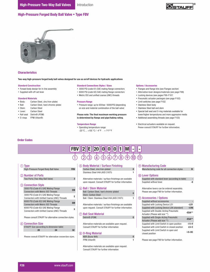
Two-Way Ball Valves IntroductionHigh-Pressure Two-Way Ball Valves
F26� �����������
High-Pressure Forged Body Ball Valve � Type FBV
Standard Connections Styles / Sizes� Z&&&�� �������|$�� #w������;����;����������� |&&&�� �������|%�� #w������;����;����������� }������ j��������:����������'!?���"������
Pressure Range� Pressure range: up to 420bar / 6000PSI (depending
on size and material combination of the ball valve)
������������ �������������������������������������������������������������������������
Temperature Range� Operating temperature range:
�%& �?������$&& �?�.��\ �� ��� � %$% ��
Two-way high-pressure forged body ball valves designed for use as on/off devices for hydraulic applications
Characteristics
Options / Accessories� ����;����������;��X�������������;����������� Alternative lever designs/materials (see page F98)� Locking devices (see pages F99-F101)� Pneumatic actuator packages (see page F102)� W���������"��������=�;���$&%�� Stainless Steel body� Stainless Steel ball and stem� Special ball seat and O-ring materials available for
�����."�;"������=�������������������;;�������������� Additional assembling threads (see page F103)
� w�����������������������<��������>������������������ �#'���������"��������������
Standard Construction� Forged body design for in-line assembly� �==��������"������������
Standard Materials� Body: Carbon Steel, zinc/iron-plated� Ball: Carbon Steel, hard chrome-plated� Stem: Carbon Steel� Lever: Carbon Steel� Ball seat: Delrin® (POM)� O-rings: FPM (Viton®)
Order Codes
� TypeHigh-Pressure Forged Body Ball Valve FBV
� Number of Ports������������������������������ 2
� Connection Style3000 PSI (Code 61) SAE Mating Flange ?������������"�}������ j��"�����
EM
3000 PSI (Code 61) SAE Mating Flange ?������������"�'��:���?�������'!?���"�����
E
6000 PSI (Code 62) SAE Mating Flange ?������������"�}������ j��"�����
SM
6000 PSI (Code 62) SAE Mating Flange ?������������"�'��:���?�������'!?���"�����
S
�������������� �#'����������������������������������
� Connection Size
�������������� �#'�����������������������������+���
STAUFF Size (according to dimension table)20 24 32
M - - - M M 2 E 20 0 0 0 2 2 E E FBV 20 20 0 0 0 0 0 0 1 1 -
Manufacturing Code MManufacturing code for all connection styles M
� Lever Options �==��������"�����������������������;������<��� - �==��������"��������� -0
#���������������������<������������=�������������������=�;���KQ�������"��������������
� Accessories / Options �==��������"������������� - �==��������"�W�X��;�Y�����WY$ -LD1 �==��������"�W�X��;�Y�����WY|����������� -LD6 �==��������"�Y��<���#���;���������Actuator (Please add size **)
-EDA**
�==��������"� ��;���#���;���������Actuator (Please add size **)
-ESA**
�==��������"�W����� ���"�����=���=������� �LS-O �==��������"�W����� ���"����������=������� �LS-C �==��������"�W����� ���"�����=������closed position -LS-OC
�����������=�;���KK�������"��������������
� Body Material / Surface FinishingCarbon Steel, zinc/iron-plated 0Stainless Steel V4A (AISI 316Ti) 1
#���������������������.�������:���"��;������������<���=�����>������?������� �#'���������"��������������
� Ball / Stem MaterialBall: Carbon Steel, hard chrome-platedStem: Carbon Steel
0
Ball / Stem: Stainless Steel V4A (AISI 316Ti) 1
#���������������������.�������:���"��;������������<���=�����>������?������� �#'���������"��������������
� Ball Seat MaterialDelrin® (POM) 0
#�������������������������������<����=�����>������?������� �#'���������"��������������
O-Ring MaterialNBR (Buna-N®) 0FPM (Viton®) 1
#�������������������������������<����=�����>������?������� �#'���������"��������������

Valv
esF
Two-Way Ball ValvesDimensions / Order Codes High-Pressure Two-Way Ball Valves
High-Pressure Forged Body Ball Valve � Type FBV 3000 PSI SAE Flange Connection (ISO 6162-1)
��<���<�������"���������;����������������<����==�����
� Body, ball and stem: Carbon Steel� Lever: Carbon Steel � Ball seat: Delrin® (POM)� O-rings: FPM (Viton®)
High-Pressure Forged Body Ball Valve � Type FBV6000 PSI SAE Flange Connection (ISO 6162-2)
When ordering the standard option as indicated in the ��<���<�������"���������;����������������<����==�����
� Body, ball and stem: Carbon Steel� Lever: Carbon Steel � Ball seat: Delrin® (POM)� O-rings: FPM (Viton®)
6000 PSI Series (Code 62) � Metric ISO Threads
6000 PSI Series (Code 62) � �������������!�"�#�� �����
������������ ��������������������������������������������������������������������������
������������ ��������������������������������������������������������������������������
STAUFF SAE Nominal Dimensions (mm/in) Nom. Pressure Weight Order CodesSize Flange Size Size DN LW L I B H h m V SW K B1 b1 t a b M H2 (bar/PSI) (kg/lbs) (Standard Option)
20 1-1/4 3232 172 80 81 107 86 40.5 16,5 17 306 68 79 16 30,2 58,7
M10171 210 7,52 FBV2EM200001M
1.26 6.77 3.15 3.19 4.21 3.39 1.59 .65 .67 12.05 2.68 3.11 .63 1.19 2.31 6.73 3000 16.54
24 1-1/2 4038 177 85 100 124 103 50 16,5 17 306 78 93 16 35,7 69,8
M12188 210 11,09 FBV2EM240001M
1.50 6.97 3.35 3.94 4.88 4.06 1.97 .65 .67 12.05 3.07 3.66 .63 1.41 2.75 7.40 3000 24.40
32 2 5048 196 100 118 138 117 59 16,5 17 306 90 102 16 42,9 77,8
M12202 210 19,29 FBV2EM320001M
1.89 7.72 3.94 4.65 5.43 4.61 2.32 .65 .67 12.05 3.54 4.02 .63 1.69 3.06 7.95 3000 42.44
40 2-1/2 50/6548 196 100 118 138 117 59 16,5 17 306 105 114 19 50,8 88,9
M12202 210 19,29 FBV2EM400001M
1.89 7.72 3.94 4.65 5.43 4.61 2.32 .65 .67 12.05 4.13 4.49 .75 2.00 3.50 7.95 3000 42.44
3000 PSI Series (Code 61) � Metric ISO Threads
3000 PSI Series (Code 61) � �������������!�"�#�� �����
STAUFF SAE Nominal Dimensions (mm/in) Nom. Pressure Weight Order CodesSize Flange Size Size DN LW L I B H h m V SW K B1 b1 t a b M H2 (bar/PSI) (kg/lbs) (Standard Option)
20 1-1/4 3232 172 80 81 107 86 40,5 16,5 17 306 68 79 16 30,2 58,7 7/16–14
UNC171 210 7,52 FBV2E200001M
1.26 6.77 3.15 3.19 4.21 3.39 1.59 .65 .67 12.05 2.68 3.11 .63 1.19 2.31 6.73 3000 16.54
24 1-1/2 4038 177 85 100 124 103 50 16,5 17 306 78 93 16 35,7 69,8 1/2–13
UNC188 210 11,09 FBV2E240001M
1.50 6.97 3.35 3.94 4.88 4.06 1.97 .65 .67 12.05 3.07 3.66 .63 1.41 2.75 7.40 3000 24.40
32 2 5048 196 100 118 138 117 59 16,5 17 306 90 102 16 42,9 77,8 1/2–13
UNC202 210 19,29 FBV2E320001M
1.89 7.72 3.94 4.65 5.43 4.61 2.32 .65 .67 12.05 3.54 4.02 .63 1.69 3.06 7.95 3000 42.44
40 2-1/2 50/6548 196 100 118 138 117 59 16,5 17 306 105 114 19 50,8 88,9 1/2–13
UNC202 210 19,29 FBV2E400001M
1.89 7.72 3.94 4.65 5.43 4.61 2.32 .65 .67 12.05 4.13 4.49 .75 2.00 3.50 7.95 3000 42.44
STAUFF SAE Nominal Dimensions (mm/in) Nom. Pressure Weight Order CodesSize Flange Size Size DN LW L I B H h m V SW K B1 b1 t a b M H2 (bar/PSI) (kg/lbs) (Standard Option)
20 1-1/4 3232 172 80 81 107 86 40,5 16,5 17 306 78 95 27 31,8 66,6
M12171 420 7,52
FBV2SM200001M1.26 6.77 3.15 3.19 4.21 3.39 1.59 .65 .67 12.05 3.07 3.74 1.06 1.25 2.62 6.73 6000 16.54
24 1-1/2 4038 177 85 100 124 103 50 16,5 17 306 94 112 30 36,5 79,4
M16188 420 11,09
FBV2SM240001M1.50 6.97 3.35 3.94 4.88 4.06 1.97 .65 .67 12.05 3.70 4.41 1.18 1.44 3.13 7.40 6000 24.40
32 2 5048 196 100 118 138 117 59 16,5 17 306 114 134 35 44,5 96,8
M20202 420 19,29
FBV2SM320001M1.89 7.72 3.94 4.65 5.43 4.61 2.32 .65 .67 12.05 4.49 5.28 1.38 1.75 3.81 7.95 6000 42.44
STAUFF SAE Nominal Dimensions (mm/in) Nom. Pressure Weight Order CodesSize Flange Size Size DN LW L I B H h m V SW K B1 b1 t a b M H2 (bar/PSI) (kg/lbs) (Standard Option)
20 1-1/4 3232 172 80 81 107 86 40,5 16,5 17 306 78 95 27 31,8 66,7 1/2–13
UNC171 420 7,52
FBV2S200001M1.26 6.77 3.15 3.19 4.21 3.39 1.59 .65 .67 12.05 3.07 3.74 1.06 1.25 2.63 6.73 6000 16.54
24 1-1/2 4038 177 85 100 124 103 50 16,5 17 306 94 112 30 36,5 79,4 5/8–11
UNC188 420 11,09
FBV2S240001M1.50 6.97 3.35 3.94 4.88 4.06 1.97 .65 .67 12.05 3.70 4.41 1.18 1.44 3.13 7.40 6000 24.40
32 2 5048 196 100 118 138 117 59 16,5 17 306 114 134 35 44,5 96,8 3/4–10
UNC202 420 19,29
FBV2S320001M1.89 7.72 3.94 4.65 5.43 4.61 2.32 .65 .67 12.05 4.49 5.28 1.38 1.75 3.81 7.95 6000 42.44
����������� F27

Two-Way Ball Valves IntroductionHigh-Pressure Two-Way Ball Valves
F28� �����������
High-Pressure Round Body Ball Valve � Type BBV29 List of ComponentsNo. Qty. Description1 1 Housing2 1 Ball3* 2 Seat4* 1 Cover O-Ring5 7-9**?����� ����6 1 Cover7 1 Stop Pin8 1 Stem9* 1 Thrust Ring10* 1 Stem O-Ring11* 1 Back-up Ring12 1 Cam Plate13 1 Snap Ring14 1 Handle15 1 Nut16 1 ���* Included in seal kit** Depending on valve size
Standard Connections Styles / Sizes� Z&&&�� �������|$�������� #w����;������������ |&&&�� �������|%�������� #w����;����������� Dual pattern: 3000 PSI (code 61) arranged horizontally
and 6000 PSI (code 62) arranged vertically� }������ j��������:����������'!?���"������
Pressure Range� Pressure range: up to 420bar / 6000PSI (depending
on size and material combination of the ball valve) ������������ �������������������������������������������������������������������������
Temperature Range� Operating temperature range:
�%& �?������$&& �?�.��\ ���������%$% ��
Two-way high-pressure round body ball valves designed for use as on/off devices for hydraulic applications
Characteristics
Options / Accessories� ����;����������;��X�������������;����������� Alternative lever designs/materials (see page F98)� Locking devices (see pages F99-F101)� Pneumatic actuator packages (see page F102)� W���������"��������=�;���$&%�� Stainless Steel body� Stainless Steel ball and stem� Special ball seat and O-ring materials available for
�����."�;"������=�������������������;;�������������
� w�����������������������<��������>������������������ �#'���������"��������������
Standard Construction� Round body design for in-line assembly� }�"�����=������������������>����=�������� Y���;�����������������������������"������������������ �==��������"�������
Standard Materials� Body: Carbon Steel, zinc/iron-plated� Ball: Carbon Steel, hard chrome-plated� Stem: Carbon Steel� Lever: Aluminium (STAUFF Size 08)
Zinc (STAUFF Sizes 12 and 16)Aluminium (STAUFF Sizes 20 to 32)
� Ball seat: Delrin® (POM)� O-rings: FPM (Viton®)
Order Codes
� TypeHigh-Pressure Round Body Ball Valve BBV
� Number of Ports������������������������������� 2
� Connection Style3000/6000 PSI (Code 61/62) SAE Direct Flange ?������������"�'��:���?�������'!?���"�����
9
3000/6000 PSI (Code 61/62) SAE Direct Flange ?������������"�}������ j��"�����
9M
�������������� �#'����������������������������������
� Connection Size
�������������� �#'�����������������������������+���
M - - - M M 2 9 32 0 0 0 2 2 9 9 BBV 32 32 0 0 0 0 0 0 1 1 -
STAUFF Size (according to dimension table):08 12 16 20 24 32
Manufacturing Code MManufacturing code for all connection styles M
� Lever Options �==��������"�����������������������;������<��� - �==��������"��������� -0
#���������������������<������������=�������������������=�;���KQ�������"��������������
� Accessories / Options �==��������"������������� - �==��������"�W�X��;�Y�����WY\ -LD4 �==��������"�W�X��;�Y�����WY{#����������� -LD5A �==��������"�Y��<���#���;���������Actuator (Please add size **)
-EDA**
�==��������"� ��;���#���;���������Actuator (Please add size **)
-ESA**
�==��������"�W����� ���"�����=���=������� �LS-O �==��������"�W����� ���"����������=������� �LS-C �==��������"�W����� ���"�����=������closed position -LS-OC
�����������=�;���KK�������"��������������
� Body Material / Surface FinishingCarbon Steel, zinc/iron-plated 0Stainless Steel V4A (AISI 316Ti) 1
#���������������������.�������:���"��;������������<���=�����>������?������� �#'���������"��������������
� Ball / Stem MaterialBall: Carbon Steel, hard chrome-platedStem: Carbon Steel
0
Ball / Stem: Stainless Steel V4A (AISI 316Ti) 1
#���������������������.�������:���"��;������������<���=�����>������?������� �#'���������"��������������
� Ball Seat MaterialDelrin® (POM) 0
#�������������������������������<����=�����>������?������� �#'���������"��������������
O-Ring MaterialNBR (Buna-N®) 0FPM (Viton®) 1
#�������������������������������<����=�����>������?������� �#'���������"��������������
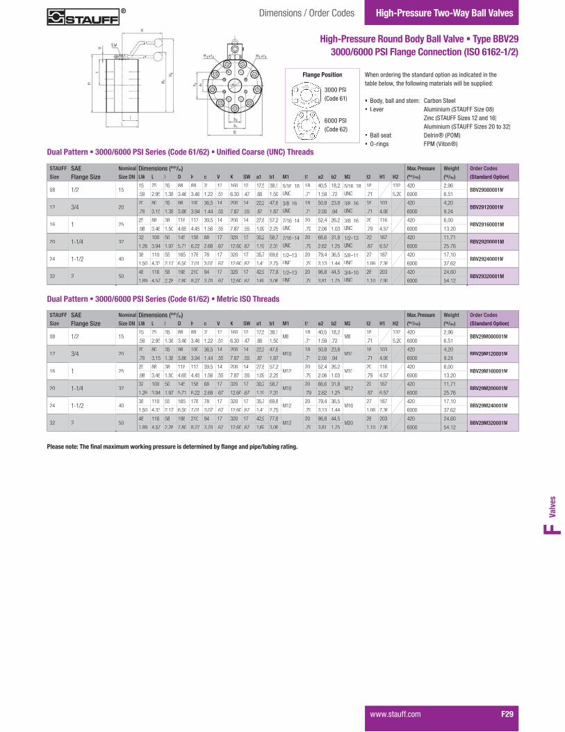
Valv
esF
Two-Way Ball ValvesDimensions / Order Codes High-Pressure Two-Way Ball Valves
����������� F29
High-Pressure Round Body Ball Valve � Type BBV29 3000/6000 PSI Flange Connection (ISO 6162-1/2)
When ordering the standard option as indicated in the��<���<�������"���������;����������������<����==�����
� Body, ball and stem: Carbon Steel� Lever: Aluminium (STAUFF Size 08)
Zinc (STAUFF Sizes 12 and 16)Aluminium (STAUFF Sizes 20 to 32)
� Ball seat: Delrin® (POM)� O-rings: FPM (Viton®)
STAUFF SAE Nominal Dimensions (mm/in) Max. Pressure Weight Order Codes
Size Flange Size Size DN LW L I D H c V K SW a1 b1 M1 t1 a2 b2 M2 t2 H1 H2 (bar/PSI) (kg/lbs) (Standard Option)
08 1/2 1515 75 35 88 88 31 13 160 12 17,5 38,1
M818 40,5 18,2
M818 132 420 2,96
BBV29M080001M.59 2.95 1.38 3.46 3.46 1.22 .51 6.30 .47 .69 1.50 .71 1.59 .72 .71 5.20 6000 6.51
12 3/4 2020 80 35 98 100 36,5 14 200 14 22,2 47,6
M1018 50,8 23,8
M1018 103 420 4,20
BBV29M120001M.79 3.15 1.38 3.86 3.94 1.44 .55 7.87 .55 .87 1.87 .71 2.00 .94 .71 4.06 6000 9.24
16 1 2525 88 38 118 113 39,5 14 200 14 27,8 57,2
M1220 52,4 26,2
M1020 116 420 6,00
BBV29M160001M.98 3.46 1.50 4.65 4.45 1.56 .55 7.87 .55 1.09 2.25 .79 2.06 1.03 .79 4.57 6000 13.20
20 1-1/4 3232 100 50 145 158 68 17 320 17 30,2 58,7
M1020 66,6 31,8
M1222 167 420 11,71
BBV29M200001M1.26 3.94 1.97 5.71 6.22 2.68 .67 12.60 .67 1.19 2.31 .79 2.62 1.25 .87 6.57 6000 25.76
24 1-1/2 4038 110 55 165 178 78 17 320 17 35,7 69,8
M1220 79,4 36,5
M1627 187 420 17,10
BBV29M240001M1.50 4.33 2.17 6.50 7.01 3.07 .67 12.60 .67 1.41 2.75 .79 3.13 1.44 1.06 7.36 6000 37.62
32 2 5048 116 58 198 210 94 17 320 17 42,9 77,8
M1220 96,8 44,5
M2028 203 420 24,60
BBV29M320001M1.89 4.57 2.28 7.80 8.27 3.70 .67 12.60 .67 1.69 3.06 .79 3.81 1.75 1.10 7.99 6000 54.12
Dual Pattern � 3000/6000 PSI Series (Code 61/62) � Metric ISO Threads
������������ ��������������������������������������������������������������������������
Flange Position
3000 PSI(Code 61)
6000 PSI(Code 62)
STAUFF SAE Nominal Dimensions (mm/in) Max. Pressure Weight Order Codes
Size Flange Size Size DN LW L I D H c V K SW a1 b1 M1 t1 a2 b2 M2 t2 H1 H2 (bar/PSI) (kg/lbs) (Standard Option)
08 1/2 1515 75 35 88 88 31 13 160 12 17,5 38,1 5/16–18
UNC
18 40,5 18,2 5/16–18 UNC
18 132 420 2,96BBV29080001M
.59 2.95 1.38 3.46 3.46 1.22 .51 6.30 .47 .69 1.50 .71 1.59 .72 .71 5.20 6000 6.51
12 3/4 2020 80 35 98 100 36,5 14 200 14 22,2 47,6 3/8–16
UNC
18 50,8 23,8 3/8–16 UNC
18 103 420 4,20BBV29120001M
.79 3.15 1.38 3.86 3.94 1.44 .55 7.87 .55 .87 1.87 .71 2.00 .94 .71 4.06 6000 9.24
16 1 2525 88 38 118 113 39,5 14 200 14 27,8 57,2 7/16–14
UNC
20 52,4 26,2 3/8–16 UNC
20 116 420 6,00BBV29160001M
.98 3.46 1.50 4.65 4.45 1.56 .55 7.87 .55 1.09 2.25 .79 2.06 1.03 .79 4.57 6000 13.20
20 1-1/4 3232 100 50 145 158 68 17 320 17 30,2 58,7 7/16–14
UNC
20 66,6 31,8 1/2–13 UNC
22 167 420 11,71BBV29200001M
1.26 3.94 1.97 5.71 6.22 2.68 .67 12.60 .67 1.19 2.31 .79 2.62 1.25 .87 6.57 6000 25.76
24 1-1/2 4038 110 55 165 178 78 17 320 17 35,7 69,8 1/2–13
UNC
20 79,4 36,5 5/8–11UNC
27 187 420 17,10BBV29240001M
1.50 4.33 2.17 6.50 7.01 3.07 .67 12.60 .67 1.41 2.75 .79 3.13 1.44 1.06 7.36 6000 37.62
32 2 5048 116 58 198 210 94 17 320 17 42,9 77,8 1/2–13
UNC
20 96,8 44,5 3/4–10 UNC
28 203 420 24,60BBV29320001M
1.89 4.57 2.28 7.80 8.27 3.70 .67 12.60 .67 1.69 3.06 .79 3.81 1.75 1.10 7.99 6000 54.12
Dual Pattern � 3000/6000 PSI Series (Code 61/62) � �������������!�"�#�� �����

Two-Way Ball Valves IntroductionHigh-Pressure Two-Way Ball Valves
F30� �����������
High-Pressure Round Body Ball Valve � Type BBV27/28No. Qty. Description1 1 Housing2 1 Ball3* 2 Seat4* 2 O-Ring5 26 2 Inner S/S Support Ring7* 1 Cover O-Ring8 9 Cover Bolts9 1 Cover10 1 ��=� ���11 1 Stem12* 1 Thrust Ring13* 1 Stem O-Ring14* 1 Back-up Ring15 2 ��� ����16 1 Stem/Handle Adaptor17 1 ���18 1 Steel Handle* Included in seal kit
List of Components
Standard Connections Styles / Sizes� Z&&&�� �������|$�������� #w����;������������ |&&&�� �������|%�������� #w����;����������� }������ j��������:����������'!?���"������
Pressure Range� Pressure range: up to 170bar / 2500PSI (depending
on size and material combination of the ball valve)
������������ ���������������������������� ��$%&������ratings. Higher pressures can be accomodated by using���'����������'���'��+�����,,:;�!���������;<=<#�
Temperature Range� Operating temperature range:
�%& �?������$&& �?�.��\ �� ��� � %$% ��
Two-way high-pressure round body ball valves designed for use as on/off devices for hydraulic applications
Characteristics
Options / Accessories� ����;����������;��X�������������;����������� Locking devices (see pages F99-F101)� Pneumatic actuator packages (see page F102)� W���������"��������=�;���$&%�� Stainless Steel body� Stainless Steel ball and stem� Special ball seat and O-ring materials available for
�����."�;"������=�������������������;;��������������
� w�����������������������<��������>������������������ �#'���������"��������������
Standard Construction� Round body design for in-line assembly� }�"�����=������������������>����=�������� Y���;�����������������������������"������������������ �==��������"�������<�����������<���������
Standard Materials� Body: Carbon Steel, zinc/iron-plated� Ball: Carbon Steel, hard chrome-plated� Stem: Carbon Steel� Lever: Carbon Steel� Ball seat: Delrin® (POM)� O-rings: FPM (Viton®)
Order Codes
� TypeHigh-Pressure Round Body Ball Valve BBV
� Number of Ports������������������������������ 2
� Connection Style3000 PSI (Code 61) SAE Direct Flange ?������������"�'��:���?�������'!?���"�����
7
3000 PSI (Code 61) SAE Direct Flange ?������������"�}������ j��"�����
7M
6000 PSI (Code 62) SAE Direct Flange ?������������"�'��:���?�������'!?���"�����
8
6000 PSI (Code 62) SAE Direct Flange ?������������"�}������ j��"�����
8M
�������������� �#'����������������������������������
� Connection Size
�������������� �#'�����������������������������+���
M - - - M M 2 7 40 0 0 0 2 2 7 7 BBV 40 40 0 0 0 0 0 0 1 1 -
STAUFF Size (according to dimension table):40 48 64 80
Manufacturing Code MManufacturing code for all connection styles M
� Lever Options �==��������"�����������������������;������<��� - �==��������"��������� -0
#���������������������<������������=�������������������=�;���KQ�������"��������������
� Accessories / Options �==��������"������������� - �==��������"�W�X��;�Y�����WY{#����������� -LD5A �==��������"�W�X��;�Y�����WY{� -LD5B �==��������"�Y��<���#���;���������Actuator (Please add size **)
-EDA**
�==��������"� ��;���#���;���������Actuator (Please add size **)
-ESA**
�==��������"�W����� ���"�����=���=������� �LS-O �==��������"�W����� ���"����������=������� �LS-C �==��������"�W����� ���"�����=������closed position -LS-OC
�����������=�;���KK�������"��������������
� Body Material / Surface FinishingCarbon Steel, zinc/iron-plated 0Stainless Steel V4A (AISI 316Ti) 1
#���������������������.�������:���"��;������������<���=�����>������?������� �#'���������"��������������
� Ball / Stem MaterialBall: Carbon Steel, hard chrome-platedStem: Carbon Steel
0
Ball / Stem: Stainless Steel V4A (AISI 316Ti) 1
#���������������������.�������:���"��;������������<���=�����>������?������� �#'���������"��������������
� Ball Seat MaterialDelrin® (POM) 0
#�������������������������������<����=�����>������?������� �#'���������"��������������
O-Ring MaterialNBR (Buna-N®) 0FPM (Viton®) 1
#�������������������������������<����=�����>������?������� �#'���������"��������������

Valv
esF
Two-Way Ball ValvesDimensions / Order Codes High-Pressure Two-Way Ball Valves
����������� F31
High-Pressure Round Body Ball Valve � Type BBV27/28 3000 PSI Flange Connection (ISO 6162-1)
When ordering the standard option as indicated in the��<���<�������"���������;����������������<����==�����
� Body, ball and stem: Carbon Steel� Lever: Carbon Steel� Ball seat: Delrin® (POM)� O-rings: FPM (Viton®)
������������ ��������������������������������������������������������������������������W����������<��:G�������������=�������������;��=��������������������<���������"��������������"��������=�������"��������<��������
Flange Position
3000 PSI(Code 61)
3000 PSI Series (Code 61) � �������������!�"�#�� �����
STAUFF SAE Nominal Dimensions (mm/in) Nom. Pressure Weight Order CodesSize Flange Size Size DN L I D H c V K SW a b M t (bar/PSI) (kg/lbs) (Standard Option)
40 2-1/2 6563 150 75 198 259 94 20 600 16 50,8 88,9
1/2–13 UNC19 170 33,50 BBV27400001M
2.48 5.91 2.95 7.80 10.20 3.70 .79 23.62 .63 2.00 3.50 .75 2500 73.70
48 3 8076 140 70 210 277 100 26 600 19 61,9 106,4
5/8–11 UNC24 138 33,50 BBV27480001M
2.99 5.51 2.76 8.27 10.91 3.94 1.02 23.62 .75 2.44 4.19 .95 2000 73.70
64 4 100100 170 85 258 326 122 27 900 24 77,8 130,2
5/8–11 UNC24 35 60,50 BBV27640001M
3.94 6.69 3.35 10.16 12.83 4.80 1.06 35.43 .94 3.06 5.13 .95 500 133.10
80 5 125118 210 105 295 377 140 33 900 36 92,1 152,4
5/8–11 UNC30 35 95,50 BBV27800001M
4.65 8.27 4.13 11.61 14.84 5.51 1.30 35.43 1.42 3.63 6.00 1.18 500 210.10
High-Pressure Round Body Ball Valve � Type BBV27/28 6000 PSI Flange Connection (ISO 6162-2)
When ordering the standard option as indicated in the��<���<�������"���������;����������������<����==�����
� Body, ball and stem: Stainless Steel� Lever: Carbon Steel� Ball seat: Delrin® (POM)� O-rings: FPM (Viton®)
STAUFF SAE Nominal Dimensions (mm/in) Nom. Pressure Weight Order CodesSize Flange Size Size DN LW L I D H c V K SW a b M t (bar/PSI) (kg/lbs) (Standard Option)
40 2-1/2 6563 170 75 218 275 100 20 600 16 123,8 58,8
M2441 420 44,50
BBV28M400001M2.48 6.69 2.95 8.58 10.83 3.94 .79 23.62 .63 4.87 2.31 1.61 6000 97.90
48 3 8076 170 70 248 307 111 21 600 19 152,4 71,4
M3047 420 55,00
BBV28M480001M2.99 6.69 2.76 9.76 12.09 4.37 .83 23.62 .75 6.00 2.81 1.85 6000 121.00
6000 PSI Series (Code 62) � Metric ISO Threads
Flange Position
6000 PSI(Code 62)
������������ ��������������������������������������������������������������������������W����������<��:G�������������=�������������;��=��������������������<���������"��������������"��������=�������"��������<��������
3000 PSI Series (Code 61) � Metric ISO Threads
STAUFF SAE Nominal Dimensions (mm/in) Nom. Pressure Weight Order CodesSize Flange Size Size DN L I D H c V K SW a b M t (bar/PSI) (kg/lbs) (Standard Option)
40 2-1/2 6563 150 75 198 259 94 20 600 16 50,8 88,9
M1219 170 33,50 BBV27M400001M
2.48 5.91 2.95 7.80 10.20 3.70 .79 23.62 .63 2.00 3.50 .75 2500 73.70
48 3 8076 140 70 210 277 100 26 600 19 61,9 106,4
M1624 138 33,50 BBV27M480001M
2.99 5.51 2.76 8.27 10.91 3.94 1.02 23.62 .75 2.44 4.19 .95 2000 73.70
64 4 100100 170 85 258 326 122 27 900 24 77,8 130,2
M1624 35 60,50 BBV27M640001M
3.94 6.69 3.35 10.16 12.83 4.80 1.06 35.43 .94 3.06 5.13 .95 500 133.10
80 5 125118 210 105 295 377 140 33 900 36 92,1 152,4
M1630 35 95,50 BBV27M800001M
4.65 8.27 4.13 11.61 14.84 5.51 1.30 35.43 1.42 3.63 6.00 1.18 500 210.10
STAUFF SAE Nominal Dimensions (mm/in) Nom. Pressure Weight Order CodesSize Flange Size Size DN LW L I D H c V K SW a b M t (bar/PSI) (kg/lbs) (Standard Option)
40 2-1/2 6563 170 75 218 275 100 20 600 16 123,8 58,8
7/8–9 UNC41 420 44,50
BBV28400001M2.48 6.69 2.95 8.58 10.83 3.94 .79 23.62 .63 4.87 2.31 1.61 6000 97.90
48 3 8076 170 70 248 307 111 21 600 19 152,4 71,4
1-1/8–7 UNC47 420 55,00
BBV28480001M2.99 6.69 2.76 9.76 12.09 4.37 .83 23.62 .75 6.00 2.81 1.85 6000 121.00
6000 PSI Series (Code 62) � �������������!�"�#�� �����
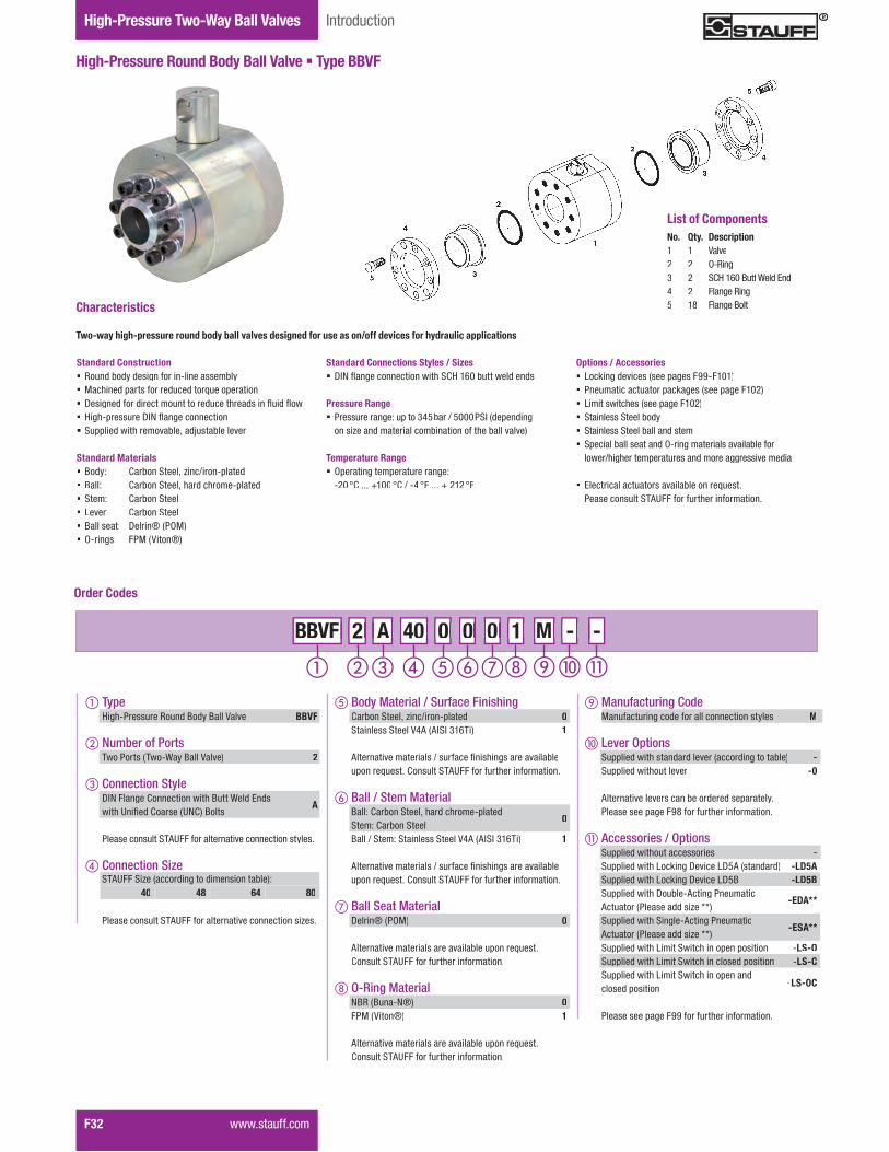
Gauge Isolator ValvesTwo-Way Ball ValvesHigh-Pressure Two-Way Ball Valves
F32� �����������
High-Pressure Round Body Ball Valve � Type BBVF
Introduction
List of ComponentsNo. Qty. Description1 1 Valve2 2 O-Ring3 2 SCH 160 Butt EndWeld E4 2 Flange Ring55 1818 Flange BoltFlange Bolt
Standard Connections Styles / Sizes� Y�!����;��������������"� ?]�$|&�<��������������
Pressure Range� Pressure range: up to 345bar / 5000PSI (depending
on size and material combination of the ball valve)
Temperature Range� Operating temperature range:
�%& �?������$&& �?�.��\ �� ��� � %$% ��
Two-way high-pressure round body ball valves designed for use as on/off devices for hydraulic applications
Characteristics
Options / Accessories� Locking devices (see pages F99-F101)� Pneumatic actuator packages (see page F102)� W���������"��������=�;���$&%�� Stainless Steel body� Stainless Steel ball and stem� Special ball seat and O-ring materials available for
�����."�;"������=�������������������;;�������������
� w�����������������������<��������>������������������ �#'���������"��������������
Standard Construction� Round body design for in-line assembly� }�"�����=������������������>����=�������� Y���;�����������������������������"������������������ ]�;"�=��������Y�!����;����������� �==��������"�������<�����������<���������
Standard Materials� Body: Carbon Steel, zinc/iron-plated� Ball: Carbon Steel, hard chrome-plated� Stem: Carbon Steel� Lever: Carbon Steel� Ball seat: Delrin® (POM)� O-rings: FPM (Viton®)
Order Codes
� TypeHigh-Pressure Round Body Ball Valve BBVF
� Number of Ports������������������������������ 2
� Connection StyleY�!�����;��?������������"�����������w������"�'��:���?�������'!?�������
A
�������������� �#'����������������������������������
� Connection Size
�������������� �#'�����������������������������+���
M - - - M M 2 A 40 0 0 0 2 2 A A BBVF 40 40 0 0 0 0 0 0 1 1 -
STAUFF Size (according to dimension table):40 48 64 80
Manufacturing Code MManufacturing code for all connection styles M
� Lever Options �==��������"�����������������������;������<��� - �==��������"��������� -0
#���������������������<������������=�������������������=�;���KQ�������"��������������
� Accessories / Options �==��������"������������� - �==��������"�W�X��;�Y�����WY{#����������� -LD5A �==��������"�W�X��;�Y�����WY{� -LD5B �==��������"�Y��<���#���;���������Actuator (Please add size **)
-EDA**
�==��������"� ��;���#���;���������Actuator (Please add size **)
-ESA**
�==��������"�W����� ���"�����=���=������� �LS-O �==��������"�W����� ���"����������=������� �LS-C �==��������"�W����� ���"�����=������closed position -LS-OC
�����������=�;���KK�������"��������������
� Body Material / Surface FinishingCarbon Steel, zinc/iron-plated 0Stainless Steel V4A (AISI 316Ti) 1
#���������������������.�������:���"��;������������<���=�����>������?������� �#'���������"��������������
� Ball / Stem MaterialBall: Carbon Steel, hard chrome-platedStem: Carbon Steel
0
Ball / Stem: Stainless Steel V4A (AISI 316Ti) 1
#���������������������.�������:���"��;������������<���=�����>������?������� �#'���������"��������������
� Ball Seat MaterialDelrin® (POM) 0
#�������������������������������<����=�����>������?������� �#'���������"��������������
O-Ring MaterialNBR (Buna-N®) 0FPM (Viton®) 1
#�������������������������������<����=�����>������?������� �#'���������"��������������
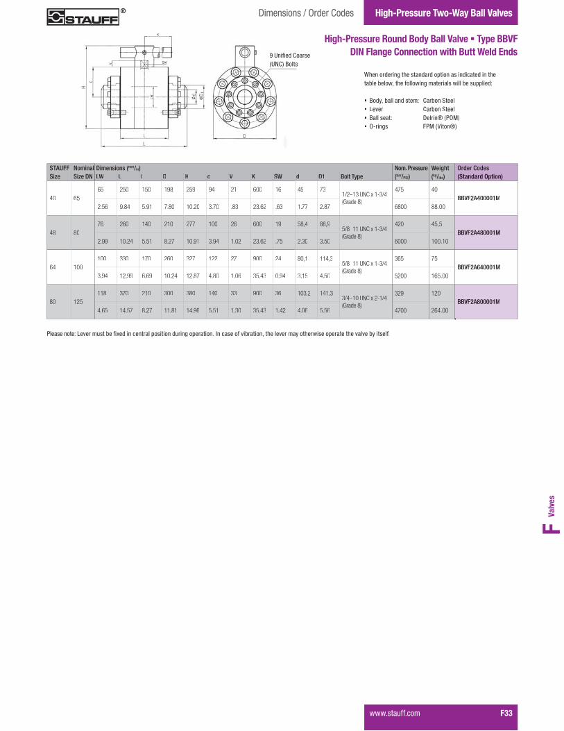
Valv
esF
Gauge Islator ValvesTwo-Way Ball ValvesHigh-Pressure Two-Way Ball Valves
����������� F33
High-Pressure Round Body Ball Valve � Type BBVF DIN Flange Connection with Butt Weld Ends
When ordering the standard option as indicated in the��<���<�������"���������;����������������<����==�����
� Body, ball and stem: Carbon Steel� Lever: Carbon Steel� Ball seat: Delrin® (POM)� O-rings: FPM (Viton®)
STAUFF Nominal Dimensions (mm/in) Nom. Pressure Weight Order CodesSize Size DN LW L I D H c V K SW d D1 Bolt Type (bar/PSI) (kg/lbs) (Standard Option)
40 6565 250 150 198 259 94 21 600 16 45 73
1/2–13 UNC x 1-3/4(Grade 8)
475 40BBVF2A400001M
2.56 9.84 5.91 7.80 10.20 3.70 .83 23.62 .63 1.77 2.87 6800 88.00
48 8076 260 140 210 277 100 26 600 19 58,4 88,9
5/8–11 UNC x 1-3/4(Grade 8)
420 45,5BBVF2A480001M
2.99 10.24 5.51 8.27 10.91 3.94 1.02 23.62 .75 2.30 3.50 6000 100.10
64 100100 330 170 260 327 122 27 900 24 80,1 114,3
5/8–11 UNC x 1-3/4(Grade 8)
365 75BBVF2A640001M
3.94 12.99 6.69 10.24 12.87 4.80 1.06 35.43 0.94 3.15 4.50 5200 165.00
80 125118 370 210 300 380 140 33 900 36 103,2 141,3
3/4–10 UNC x 2-1/4(Grade 8)
329 120BBVF2A800001M
4.65 14.57 8.27 11.81 14.96 5.51 1.30 35.43 1.42 4.06 5.56 4700 264.00
Dimensions / Order Codes
K�'��:���?������(UNC) Bolts
�������������W����������<��:G�������������=�������������;��=��������������������<���������"��������������"��������=�������"��������<��������

Gauge Isolator ValvesTwo-Way Ball ValvesHigh-Pressure Two-Way Ball Valves
F34� �����������
High-Pressure Round Body Ball Valve � Type BBV
Introduction
Standard Connections Styles / Sizes� %{&�<���.�Z|&&�� ���������� j�|$|\����;������������ \&&�<���.�{Q&&�� ���������� j�|$|\����;������������ Metric ISO threads
Pressure Range� Pressure range: up to 400bar / 5800PSI (depending
on size and material combination of the ball valve)
������������ ��������������������������������������������������������������������������
Temperature Range� Operating temperature range:
�%& �?������$&& �?�.��\ �� ��� � %$% ��
Two-way high-pressure round body ball valves designed for use as on/off devices for hydraulic applications
Characteristics
Options / Accessories� Alternative lever designs/materials (see page F98)� Locking devices (see pages F99-F101)� Pneumatic actuator packages (see page F102)� W���������"��������=�;���$&%�� Stainless Steel body� Stainless Steel ball and stem� Special ball seat and O-ring materials available for
�����."�;"������=�������������������;;�������������
� w�����������������������<��������>������������������ �#'���������"��������������
Standard Construction� Round body design for in-line assembly� }�"�����=������������������>����=�������� Y���;�����������������������������"������������������ �==��������"�������
Standard Materials� Body: Carbon Steel, zinc/iron-plated� Ball: Carbon Steel, hard chrome-plated� Stem: Carbon Steel� Lever: Aluminium (STAUFF Size 08)
Zinc (STAUFF Sizes 12 and 16)Carbon Steel (STAUFF Sizes 20 and 64)
� Ball seat: Delrin® (POM)� O-rings: FPM (Viton®)
Order Codes
� TypeHigh-Pressure Round Body Ball Valve BBV
� Number of Ports������������������������������ 2
� Connection Style250 bar / 3600 PSI Series ISO 6164����;��?������������"�}������ j��"�����
D1
400 bar / 5800 PSI Series ISO 6164����;��?������������"�}������ j��"�����
D2
250 bar / 3600 PSI Series and400 bar / 5800 PSI Series ISO 6164 D(1-2)����;��?������������"�}������ j��"�����
�������������� �#'����������������������������������
� Connection Size
�������������� �#'�����������������������������+���
M - - - M M 2 D2 48 0 0 0 2 2 D2 D2 BBV 48 48 0 0 0 0 0 0 1 1 -
STAUFF Size (according to dimension table):08 12 16 20 24 32 40 48 64
Manufacturing Code MManufacturing code for all connection styles M
� Lever Options �==��������"�����������������������;������<��� - �==��������"��������� -0
#���������������������<������������=�������������������=�;���KQ�������"��������������
� Accessories / Options �==��������"������������� - �==��������"�W�X��;�Y�����WY\ -LD4 �==��������"�W�X��;�Y�����WY{������������ -LD5B �==��������"�Y��<���#���;���������Actuator (Please add size **)
-EDA**
�==��������"� ��;���#���;���������Actuator (Please add size **)
-ESA*
�==��������"�W����� ���"�����=���=������� �LS-O �==��������"�W����� ���"����������=������� �LS-C �==��������"�W����� ���"�����=������closed position -LS-OC
�����������=�;���KK�������"��������������
� Body Material / Surface FinishingCarbon Steel, zinc/iron-plated 0Stainless Steel V4A (AISI 316Ti) 1
#���������������������.�������:���"��;������������<���=�����>������?������� �#'���������"��������������
� Ball / Stem MaterialBall: Carbon Steel, hard chrome-platedStem: Carbon Steel
0
Ball / Stem: Stainless Steel V4A (AISI 316Ti) 1
#���������������������.�������:���"��;������������<���=�����>������?������� �#'���������"��������������
� Ball Seat MaterialDelrin® (POM) 0
#�������������������������������<����=�����>������?������� �#'���������"��������������
O-Ring MaterialNBR (Buna-N®) 0FPM (Viton®) 1
#�������������������������������<����=�����>������?������� �#'���������"��������������
No. Qty. Description1 1 Housing2 1 Ball3* 2 Seat4* 2 O-Ring5 2 Outer S/S Support Ring6 2 Inner S/S Support Ring7* 1 Cover O-Ring8 9 Cover Bolts9 1 Cover10 1 ��=� ���11 1 Stem12* 1 Thrust Ring13* 1 Stem O-Ring14* 1 Back-up Ring15 2 ��� ����16 1 Stem/Handle Adaptor17 1 ���18 1 Steel Handle* Included in seal kit
List of Components

Valv
esF
����������� F35
Dimensions / Order Codes High-Pressure Two-Way Ball Valves
High-Pressure Round Body Ball Valve � Type BBVISO Flange Connection (ISO 6164)
When ordering the standard option as indicated in the��<���<�������"���������;����������������<����==�����
� Body, ball and stem: Carbon Steel � Lever: Aluminium (STAUFF Size 08) Zinc (STAUFF Sizes 12 and 16) Carbon Steel (STAUFF Sizes 20 to 64) Ball seat: Delrin® (POM)
� O-rings: FPM (Viton®)
STAUFF Nominal Dimensions (mm/in) Nom. Pressure Weight Order CodesSize Size DN LW LWG L l D H c V K SW LK M t H1 H2 (bar/PSI) (kg/lbs) (Standard Option)
08 1315 15 85 45 78 83 31 13 160 12 42 1
4 x M816 127 250 400 2,90
BBV2D(1-2)080001M 2
.59 .59 3.35 1.77 3.07 3.27 1.22 .51 6.30 .47 1.65 1 .63 5.00 3600 5800 4.84
12 1920 20 88 38 119 110 36.5 14 200 14 50
4 x M815 114 250 400 6,80
BBV2D(1-2)120001M 2
.79 .79 3.46 1.50 4.69 4.33 1.44 .55 7.87 .55 1.97 .59 4.49 3600 5800 14.96
16 2525 25 88 38 126 117 39.5 14 200 14 62
4 x M1020 120 250 400 7,20
BBV2D(1-2)160001M 2.98 .98 3.46 1.50 4.96 4.61 1.56 .55 7.87 .55 2.44 .79 4.72 3600 5800 15.84
20 3232 32 105 50 145 158 68 17 320 17 73
4 x M1221 167 250 400 12,50
BBV2D(1-2)200001M 21.26 1.26 4.13 1.97 5.71 6.22 2.68 .67 12.60 .67 2.87 .83 6.57 3600 5800 27.50
24 3838 38 110 55 165 178 78 17 320 17 85
4 x M1624.5 187 250 400 16,60
BBV2D(1-2)240001M 21.50 1.50 4.33 2.17 6.50 7.01 3.07 .67 12.60 .67 3.35 .96 7.36 3600 5800 36.52
32 5148 47 116 58 198 210 94 17 320 17 98
4 x M1625.5 219 250 400 24,90
BBV2D(1-2)320001M 21.89 1.85 4.57 2.28 7.80 8.27 3.70 .67 12.60 .67 3.86 1.00 8.62 3600 5800 54.78
40 5648 58 123 58 198 210 94 17 320 17 118
4 x M2033 219 250 400 26,60
BBV2D(1-2)400001M 21.89 2.28 4.84 2.28 7.80 8.27 3.70 .67 12.60 .67 4.65 1.30 8.62 3600 5800 58.52
48 6363 70 150 75 208 270 100 20 600 16 145
4 x M2033 250 36,90
BBV2D1480001M2.48 2.76 5.91 2.95 8.19 1.63 3.94 .79 23.62 .63 5.71 1.30 3600 81.18
250 bar / 3600 PSI Series (ISO 6164) � Metric ISO Threads
�Y!{| �Y!|Z
STAUFF Nominal Dimensions (mm/in) Nom. Pressure Weight Order CodesSize Size DN LW LWG L l D H c V K SW LK M t H1 H2 (bar/PSI) (kg/lbs) (Standard Option)
08 1315 15 85 45 78 83 31 13 160 12 42 1
4 x M816 127 400 2.90
BBV2D(1-2)080001M 2
.59 .59 3.35 1.77 3.07 3.27 1.22 .51 6.30 .47 1.65 1 .63 5.00 5800 4.84
12 1920 20 88 38 119 110 36.5 14 200 14 50
4 x M815 114 400 6.80
BBV2D(1-2)120001M 2
.79 .79 3.46 1.50 4.69 4.33 1.44 .55 7.87 .55 1.97 .59 4.49 5800 14.96
16 2525 25 88 38 126 117 39.5 14 200 14 62
4 x M1020 120 400 7.20
BBV2D(1-2)160001M 2
.98 .98 3.46 1.50 4.96 4.61 1.56 .55 7.87 .55 2.44 .79 4.72 5800 15.84
20 3232 32 105 50 145 158 68 17 320 17 73
4 x M1221 167 400 12.50
BBV2D(1-2)200001M 2
1.26 1.26 4.13 1.97 5.71 6.22 2.68 .67 12.60 .67 2.87 .83 6.57 5800 27.50
24 3838 38 110 55 165 178 78 17 320 17 85
4 x M1624.5 187 400 16.60
BBV2D(1-2)240001M 2
1.50 1.50 4.33 2.17 6.50 7.01 3.07 .67 12.60 .67 3.35 .96 7.36 5800 36.52
32 5148 47 116 58 198 210 94 17 320 17 98
4 x M1625.5 219 400 24.90
BBV2D(1-2)320001M 2
1.89 1.85 4.57 2.28 7.80 8.27 3.70 .67 12.60 .67 3.86 1.00 8.62 5800 54.78
40 5648 58 123 58 198 210 94 17 320 17 118
4 x M2033 219 400 26.60
BBV2D(1-2)400001M 2
1.89 2.28 4.84 2.28 7.80 8.27 3.70 .67 12.60 .67 4.65 1.30 8.62 5800 58.52
48 6365 58 150 75 224 286 108 20 600 16 145
4 x M2437.5 400 42.53
BBV2D2480001M2.56 2.28 5.91 2.95 8.82 11.26 4.25 .79 23.62 .63 5.71 1.47 5800 93.56
64 8076 74 140 70 228 293 107 25 600 19 175
4 x M3035 400 51.00
BBV2D2640001M2.99 2.91 5.51 2.76 8.98 11.54 4.21 .98 23.62 .75 6.89 1.38 5800 112.20
400 bar / 5800 PSI Series (ISO 6164) � Metric ISO Threads
������������ ��������������������������������������������������������������������������W����������<��:G�������������=�������������;��=��������������������<���������"��������������"��������=�������"��������<��������
1 Y���������W���������<��\{��2 ����<������%{&�<���.�Z|&&�� �������������\&&�<���.�{Q&&�� ���������

Gauge Isolator ValvesTwo-Way Ball ValvesHigh-Pressure Two-Way Ball Valves
F36� �����������
High-Pressure Round Body Ball Valve � Type BBV
Introduction
Standard Connections Styles / Sizes� %{&�<���.�Z|&&�� ���������?w�j��~��|Z�]����;����������� \&&�<���.�{Q&&�� ���������?w�j��~��|Z�]����;����������� Metric ISO threads
Pressure Range� Pressure range: up to 400bar / 5800PSI (depending
on size and material combination of the ball valve)
������������ ��������������������������������������������������������������������������
Temperature Range� Operating temperature range:
�%& �?������$&& �?�.��\ �� ��� � %$% ��
Two-way high-pressure round body ball valves designed for use as on/off devices for hydraulic applications
Characteristics
Options / Accessories� Alternative lever designs/materials (see page F98)� Locking devices (see pages F99-F101)� Pneumatic actuator packages (see page F102)� W���������"��������=�;���$&%�� Stainless Steel body� Stainless Steel ball and stem� Special ball seat and O-ring materials available for
�����."�;"������=�������������������;;�������������
� w�����������������������<��������>������������������ �#'���������"��������������
Standard Construction� Round body design for in-line assembly� }�"�����=������������������>����=�������� Y���;�����������������������������"������������������ �==��������"�������
Standard Materials� Body: Carbon Steel, zinc/iron-plated� Ball: Carbon Steel, hard chrome-plated� Stem: Carbon Steel� Lever: Carbon Steel� Ball seat: Delrin® (POM)� O-rings: FPM (Viton®)
Order Codes
� TypeHigh-Pressure Round Body Ball Valve BBV
� Number of Ports������������������������������ 2
� Connection Style250 bar / 3600 PSI Series CETOP ����;��?������������"�}������ j��"�����
Y1
400 bar / 5800 PSI Series CETOP ����;��?������������"�}������ j��"�����
Y2
250 bar / 3600 PSI Seriesand400 bar / 5800 PSI Series CETOP Y(1-2)����;��?������������"�}������ j��"�����
�������������� �#'����������������������������������
� Connection Size
�������������� �#'�����������������������������+���
M - - - M M 2 Y1 48 0 0 0 2 2 Y1 Y1 BBV 48 48 0 0 0 0 0 0 1 1 -
STAUFF Size (according to dimension table):08 12 16 20 24 32 40 48 64
Manufacturing Code MManufacturing code for all connection styles M
� Lever Options �==��������"�����������������������;������<��� - �==��������"��������� -0
#���������������������<������������=�������������������=�;���KQ�������"��������������
� Accessories / Options �==��������"������������� - �==��������"�W�X��;�Y�����WY\ -LD4 �==��������"�W�X��;�Y�����WY{������������ -LD5B �==��������"�Y��<���#���;���������Actuator (Please add size **)
-EDA**
�==��������"� ��;���#���;���������Actuator (Please add size **)
-ESA**
�==��������"�W����� ���"�����=���=������� �LS-O �==��������"�W����� ���"����������=������� �LS-C �==��������"�W����� ���"�����=������closed position -LS-OC
�����������=�;���KK�������"��������������
� Body Material / Surface FinishingCarbon Steel, zinc/iron-plated 0Stainless Steel V4A (AISI 316Ti) 1
#���������������������.�������:���"��;������������<���=�����>������?������� �#'���������"��������������
� Ball / Stem MaterialBall: Carbon Steel, hard chrome-platedStem: Carbon Steel
0
Ball / Stem: Stainless Steel V4A (AISI 316Ti) 1
#���������������������.�������:���"��;������������<���=�����>������?������� �#'���������"��������������
� Ball Seat MaterialDelrin® (POM) 0
#�������������������������������<����=�����>������?������� �#'���������"��������������
O-Ring MaterialNBR (Buna-N®) 0FPM (Viton®) 1
#�������������������������������<����=�����>������?������� �#'���������"��������������
No. Qty. Description1 1 Housing2 1 Ball3* 2 Seat4* 2 O-Ring5 2 Outer S/S Support Ring6 2 Inner S/S Support Ring7* 1 Cover O-Ring8 9 Cover Bolts9 1 Cover10 1 ��=� ���11 1 Stem12* 1 Thrust Ring13* 1 Stem O-Ring14* 1 Back-up Ring15 2 ��� ����16 1 Stem/Handle Adaptor17 1 ���18 1 Steel Handle* Included in seal kit
List of Components

Valv
esF
����������� F37
Dimensions / Order Codes High-Pressure Two-Way Ball Valves
When ordering the standard option as indicated in the��<���<�������"���������;����������������<����==�����
� Body, ball and stem: Carbon Steel � Lever: Carbon Steel� Ball seat: Delrin® (POM)� O-rings: FPM (Viton®)
STAUFF Flange Nominal Dimensions (mm/in) Nom. Pressure Weight Order CodesSize Size Size DN LW LWG L l D H c V K SW A M t H2 (bar/PSI) (kg/lbs) (Standard Option)
32 2 5148 47 116 58 198 210 94 17 320 17 69,4
M1624,5 219 250 400 24,90
BBV2Y(1-2)320001M 1
1.89 1.85 4.57 2.28 7.80 8.27 3.70 .67 12.60 .67 2.73 .96 8.62 3600 5800 54.78
40 2-1/2 5648 58 123 58 198 210 94 17 320 17 83,4
M2033 219 250 400 26,60
BBV2Y(1-2)400001M 1
1.89 2.28 4.84 2.28 7.80 8.27 3.70 .67 12.60 .67 3.28 1.30 8.62 3600 5800 58.52
48 3 6563 70 150 75 208 270 100 20 600 16 102,5
M2033 250 36,90
BBV2Y1480001M2.48 2.76 5.91 2.95 8.19 1.63 3.94 .79 23.62 .63 4.04 1.30 3600 81.18
64 4 100100 90 200 100 258 326 122 26 900 24 113,2
M2440 250 70,40
BBV2Y1640001M3.94 3.54 7.87 3.93 10.16 12.83 4.80 1.02 35.43 .94 4.46 1.57 3600 154.88
250 bar / 3600 PSI Series (CETOP RP 63 H) � Metric ISO Threads
�Y!{| �Y!|{
400 bar / 5800 PSI Series (CETOP RP 63 H) � Metric ISO Threads
������������ ��������������������������������������������������������������������������W����������<��:G�������������=�������������;��=��������������������<���������"��������������"��������=�������"��������<��������
1 ����<������%{&�<���.�Z|&&�� �������������\&&�<���.�{Q&&�� ���������2 #�����<��������>�����
STAUFF Flange Nominal Dimensions (mm/in) Nom. Pressure Weight Order CodesSize Size Size DN LW LWG L l D H c V K SW A M t H2 (bar/PSI) (kg/lbs) (Standard Option)
32 2 5148 47 116 58 198 210 94 17 320 17 69,4
M1624,5 219 250 400 24,90
BBV2Y(1-2)320001M 1
1.89 1.85 4.57 2.28 7.80 8.27 3.70 .67 12.60 .67 2.73 .96 8.62 3600 5800 54.78
40 2-1/2 5648 58 123 58 198 210 94 17 320 17 83,4
M2033 219 250 400 26,60
BBV2Y(1-2)400001M 1
1.89 2.28 4.84 2.28 7.80 8.27 3.70 .67 12.60 .67 3.28 1.30 8.62 3600 5800 58.52
48 3 6563 58 150 75 224 286 108 20 600 16 102,5
M2037.5 400 42.53
BBV2Y2480001M 2
2.56 2.28 5.91 2.95 8.82 11.26 4.25 .79 23.62 .63 4.04 1.47 5800 93.56
64 4 8076 74 140 70 228 293 107 25 600 19 113,2
M2435 400 51.00
BBV2Y2640001M 2
2.99 2.91 5.51 2.76 8.98 11.54 4.21 .98 23.62 .75 4.46 1.38 5800 112.20
High-Pressure Round Body Ball Valve � Type BBVCETOP Flange Connection (CETOP RP 63 H)
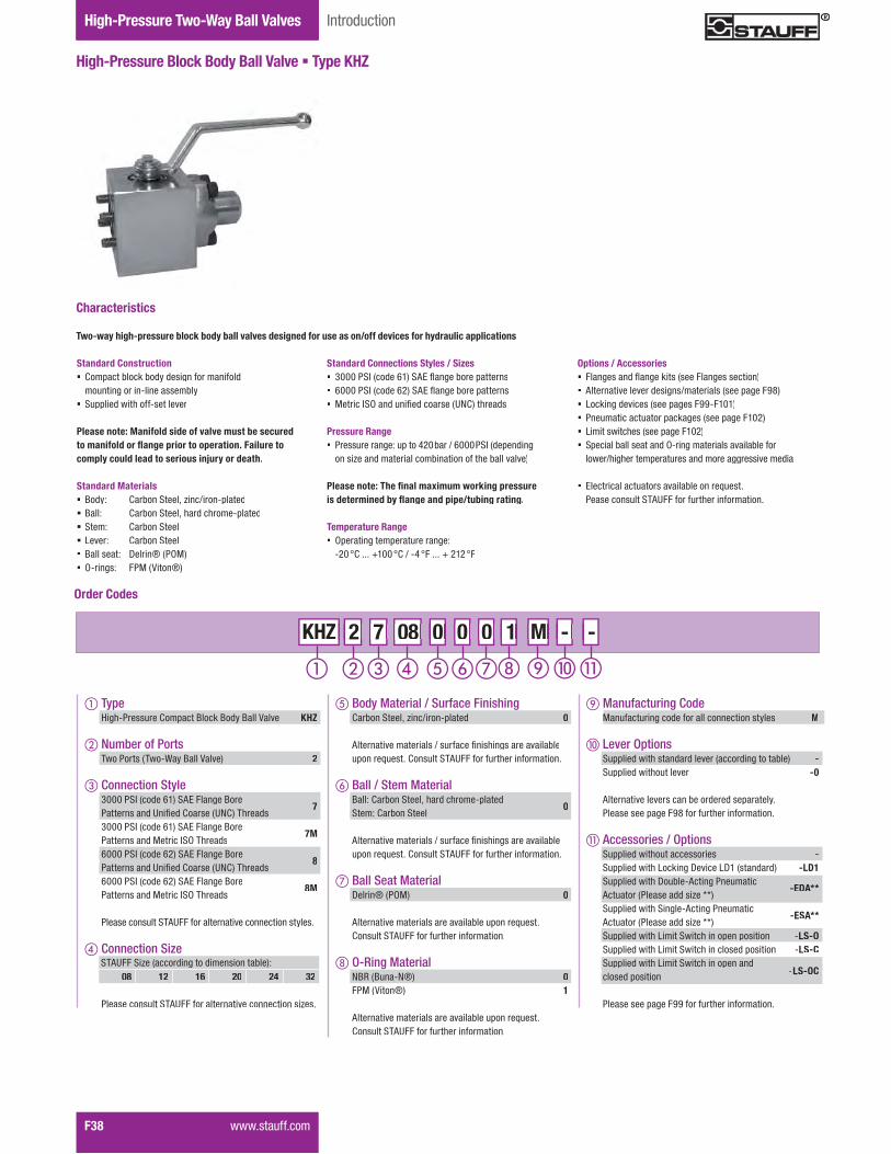
Gauge Isolator ValvesTwo-Way Ball ValvesHigh-Pressure Two-Way Ball Valves
F38� �����������
High-Pressure Block Body Ball Valve � Type KHZ
Introduction
Standard Connections Styles / Sizes� Z&&&�� �������|$�� #w�����;��<����=�������� |&&&�� �������|%�� #w�����;��<����=�������� }������ j��������:�����������'!?���"������
Pressure Range� Pressure range: up to 420 bar / 6000 PSI (depending
on size and material combination of the ball valve)
������������ ���������������������������������������������������������������������������
Temperature Range� Operating temperature range:
�%&��?������$&&��?�.��\����������%$%���
Two-way high-pressure block body ball valves designed for use as on/off devices for hydraulic applications
Characteristics
Options / Accessories� ����;�����������;��X�������������;����������� Alternative lever designs/materials (see page F98)� Locking devices (see pages F99-F101)� Pneumatic actuator packages (see page F102)� W���������"��������=�;���$&%�� Special ball seat and O-ring materials available for
�����."�;"������=�������������������;;�������������
� w�����������������������<��������>������������������ �#'���������"��������������
Standard Construction� Compact block body design for manifold
mounting or in-line assembly� �==��������"������������
Please note: Manifold side of valve must be secured�����?��������������������������;�������comply could lead to serious injury or death.
Standard Materials� Body: Carbon Steel, zinc/iron-plated� Ball: Carbon Steel, hard chrome-plated� Stem: Carbon Steel� Lever: Carbon Steel� Ball seat: Delrin® (POM)� O-rings: FPM (Viton®)
Order Codes
� Type High-Pressure Compact Block Body Ball Valve KHZ
� Number of Ports� ������������������������������� 2
� Connection Style 3000 PSI (code 61) SAE Flange Bore � �������������'��:����?�������'!?���"������
7
3000 PSI (code 61) SAE Flange Bore Patterns and Metric ISO Threads
7M
6000 PSI (code 62) SAE Flange Bore� �������������'��:����?�������'!?���"������
8
6000 PSI (code 62) SAE Flange Bore Patterns and Metric ISO Threads
8M
� �������������� �#'����������������������������������
� Connection Size
� �������������� �#'�����������������������������+���
M - - - M M 2 7 08 0 0 0 2 2 7 7 KHZ 08 08 0 0 0 0 0 0 1 1 -
STAUFF Size (according to dimension table):08 12 16 20 24 32
Manufacturing Code MManufacturing code for all connection styles M
� Lever Options� �==��������"�����������������������;������<��� -� �==��������"���������� -0
� #���������������������<������������=��������� �����������=�;���KQ�������"��������������
� Accessories / Options� �==��������"������������� -� �==��������"�W�X��;�Y�����WY$����������� -LD1� �==��������"�Y��<���#���;��������� Actuator (Please add size **)
-EDA**
� �==��������"� ��;���#���;��������� Actuator (Please add size **)
-ESA**
� �==��������"�W����� ���"�����=���=�������� �LS-O� �==��������"�W����� ���"����������=�������� �LS-C� �==��������"�W����� ���"�����=������ closed position -LS-OC
� �����������=�;���KK�������"��������������
� Body Material / Surface Finishing Carbon Steel, zinc/iron-plated 0
� #���������������������.�������:����"��;������������<��� �=�����>������?������� �#'���������"��������������
� Ball / Stem Material Ball: Carbon Steel, hard chrome-plated Stem: Carbon Steel
0
� #���������������������.�������:����"��;������������<��� �=�����>������?������� �#'���������"��������������
� Ball Seat Material Delrin® (POM) 0
� #�������������������������������<����=�����>������� ?������� �#'���������"��������������
O-Ring Material NBR (Buna-N®) 0 FPM (Viton®) 1
� #�������������������������������<����=�����>������� ?������� �#'���������"��������������

Valv
esF
����������� F39
High-Pressure Block Body Ball Valve � Type KHZ 3000 PSI SAE Flange Connection (ISO 6162-1)
��<���<�������"���������;����������������<����==�����
� Body, ball and stem: Carbon Steel� Lever: Carbon Steel� Ball seat: Delrin® (POM)� O-rings: FPM (Viton®)
STAUFF Flange Nominal Dimensions (mm/in) Nom. Pressure Weight Order CodesSize Size Size DN LW D L I H h m K SW V a b M t d1 d2 t1 H2 (bar/PSI) (kg/lbs) (Standard Option)
08 1/2 1313 13 68 34 72 58 30 115 9 11 17,5 38,1
M815 8,5 13,5 9 109 210 1,80
KHZ27M080001M.51 .51 2.68 1.34 2.83 2.28 1.18 4.53 .35 .43 .69 1.50 .59 .33 .53 .35 4,29 3000 3.96
12 3/4 2020 20 70 35 93 75 37,5 170 14 14 22,3 47,6
M1017 10,5 16,5 11 146 210 2,80
KHZ27M120001M.79 .79 2.76 1.38 3.66 2.95 1.48 6.69 .55 .55 .88 1.87 .67 .41 .65 .43 5,75 3000 6.16
16 1 2525 25 78 39 103 84,5 44 170 14 14 26,2 52,4
M1017 10,5 16,5 11 155 210 3,90
KHZ27M160001M.98 .98 3.07 1.54 4.06 3.33 1.73 6.69 .55 .55 1.03 2.06 .67 .41 .65 .43 6,10 3000 8.58
20 1-1/4 3225 32 90 45 118,5 100 50 170 14 14 30,2 58,7
M1021 10,5 16,5 11 171 210 6,50
KHZ27M200001M.98 1.26 3.54 1.77 4.67 3.94 1.97 6.69 .55 .55 1.19 2.31 .83 .41 .65 .43 6,73 3000 14.30
24 1-1/2 4032 38 99 49,5 141,5 120 60 306 17 17 35,7 69,9
M1221 13 19 13 206 210 10,50
KHZ27M240001M1.26 1.50 3.90 1.95 5.57 4.72 2.36 12.05 .67 .67 1.41 2.75 .83 .51 .75 .51 8,11 3000 23.10
32 2 5038 49 120 60 158,5 137,5 70 306 17 17 42,9 77,8
M1221 13 19 13 223 210 16,50
KHZ27M320001M1.50 1.93 4.72 2.36 6.24 5.41 2.76 12.05 .67 .67 1.69 3.06 .83 .51 .75 .51 8,78 3000 36.30
Dimensions / Order Codes
3000 PSI Series (Code 61) � Metric ISO Threads
������������ �������������������������������������������������������������������������
����;�������<���������������������������������
STAUFF Nominal RecommendationsSize Size DN Bolt S1 (min) Bolt S2 (min) O-ring (Included in Delivery)
08 13M8 x 30 - 10.9 M8 x 70 - 10.9
18,64 x 3,535/16–18 UNC x 1-1/4 - Gr. 8 5/16–18 UNC x 2-3/4 - Gr. 8
12 20M10 x 30 - 10.9 M10 x 80 - 10.9
24,99 x 3,533/8–16 UNC x 1-1/4 - Gr. 8 3/8–16 UNC x 3-1/4 - Gr. 8
16 25M10 x 30 - 10.9 M10 x 80 - 10.9
32,92 x 3,533/8–16 UNC x 1-1/4 - Gr. 8 3/8–16UNC x 3-1/4 - Gr. 8
20 32M10 x 30 - 10.9 M10 x 90 - 10.9
37,69 x 3,537/16–14 UNC x 1-1/4 - Gr. 8 7/16–14 UNC x 3-1/2 - Gr. 8
24 40M12 x 35 - 10.9 M12 x 100 - 10.9
47,22 x 3,531/2–13 UNC x 1-1/2 - Gr. 8 1/2–13 UNC x 4 - Gr. 8
32 50M12 x 35 - 10.9 M12 x 120 - 10.9
56,74 x 3,531/2–13 UNC x 1-1/2 - Gr. 8 1/2–13 UNC x 4-3/4 - Gr. 8
Recommended Bolts and O-Rings
OO-Ring(Included inDelivery)
High-Pressure Two-Way Ball Valves
3000 PSI Series (Code 61) � �������������!�"�#�� �����
STAUFF Flange Nominal Dimensions (mm/in) Nom. Pressure Weight Order CodesSize Size Size DN LW D L I H h m K SW V a b M t d1 d2 t1 H2 (bar/PSI) (kg/lbs) (Standard Option)
08 1/2 1313 13 68 34 72 58 30 115 9 11 17,5 38,1
5/16–18 UNC15 8,5 13,5 9 109 210 1,80
KHZ27080001M.51 .51 2.68 1.34 2.83 2.28 1.18 4.53 .35 .43 .69 1.50 .59 .33 .53 .35 4,29 3000 3.96
12 3/4 2020 20 70 35 93 75 37,5 170 14 14 22,3 47,6
3/8–16 UNC17 10,5 16,5 11 146 210 2,80
KHZ27120001M.79 .79 2.76 1.38 3.66 2.95 1.48 6.69 .55 .55 .88 1.87 .67 .41 .65 .43 5,75 3000 6.16
16 1 2525 25 78 39 103 84,5 44 170 14 14 26,2 52,4
3/8–16 UNC17 10,5 16,5 11 155 210 3,90
KHZ27160001M.98 .98 3.07 1.54 4.06 3.33 1.73 6.69 .55 .55 1.03 2.06 .67 .41 .65 .43 6,10 3000 8.58
20 1-1/4 3225 32 90 45 118,5 100 50 170 14 14 30,2 58,7
7/16–14 UNC21 10,5 16,5 11 171 210 6,50
KHZ27200001M.98 1.26 3.54 1.77 4.67 3.94 1.97 6.69 .55 .55 1.19 2.31 .83 .41 .65 .43 6,73 3000 14.30
24 1-1/2 4032 38 99 49,5 141,5 120 60 306 17 17 35,7 69,9
1/2–13 UNC21 13 19 13 206 210 10,50
KHZ27240001M1.26 1.50 3.90 1.95 5.57 4.72 2.36 12.05 .67 .67 1.41 2.75 .83 .51 .75 .51 8,11 3000 23.10
32 2 5038 49 120 60 158,5 137,5 70 306 17 17 42,9 77,8
1/2–13 UNC21 13 19 13 223 210 16,50
KHZ27320001M1.50 1.93 4.72 2.36 6.24 5.41 2.76 12.05 .67 .67 1.69 3.06 .83 .51 .75 .51 8,78 3000 36.30
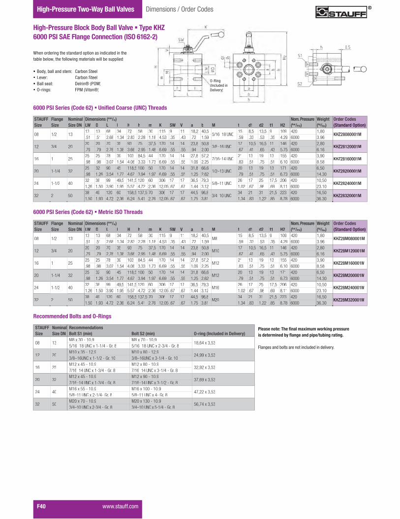
Gauge Isolator ValvesTwo-Way Ball ValvesHigh-Pressure Two-Way Ball Valves
F40� �����������
High-Pressure Block Body Ball Valve � Type KHZ6000 PSI SAE Flange Connection (ISO 6162-2)
When ordering the standard option as indicated in the��<���<�������"���������;����������������<����==�����
� Body, ball and stem: Carbon Steel� Lever: Carbon Steel� Ball seat: Delrin® (POM)� O-rings: FPM (Viton®)
Dimensions / Order Codes
6000 PSI Series (Code 62) � �������������!�"�#�� �����
STAUFF Flange Nominal Dimensions (mm/in) Nom. Pressure Weight Order CodesSize Size Size DN LW D L I H h m K SW V a b M t d1 d2 t1 H2 (bar/PSI) (kg/lbs) (Standard Option)
08 1/2 1313 13 68 34 72 58 30 115 9 11 18,2 40,5
5/16–18 UNC15 8,5 13,5 9 109 420 1,80
KHZ28080001M.51 .51 2.68 1.34 2.83 2.28 1.18 4.53 .35 .43 .72 1.59 .59 .33 .53 .35 4.29 6000 3.96
12 3/4 2020 20 70 35 93 75 37,5 170 14 14 23,8 50,8
3/8–16 UNC17 10,5 16,5 11 146 420 2,80
KHZ28120001M.79 .79 2.76 1.38 3.66 2.95 1.48 6.69 .55 .55 .94 2.00 .67 .41 .65 .43 5.75 6000 6.16
16 1 2525 25 78 39 103 84,5 44 170 14 14 27,8 57,2
7/16–14 UNC21 13 19 13 155 420 3,90
KHZ28160001M.98 .98 3.07 1.54 4.06 3.33 1.73 6.69 .55 .55 1.09 2.25 .83 .51 .75 .51 6.10 6000 8.58
20 1-1/4 3225 32 90 45 118,5 100 50 170 14 14 31,8 66,6
1/2–13 UNC20 13 19 13 171 420 6,50
KHZ28200001M.98 1.26 3.54 1.77 4.67 3.94 1.97 6.69 .55 .55 1.25 2.62 .79 .51 .75 .51 6.73 6000 14.30
24 1-1/2 4032 38 99 49,5 141,5 120 60 306 17 17 36,5 79,3
5/8–11 UNC26 17 25 17,5 206 420 10,50
KHZ28240001M1.26 1.50 3.90 1.95 5.57 4.72 2.36 12.05 .67 .67 1.44 3.12 1.02 .67 .98 .69 8.11 6000 23.10
32 2 5038 49 120 60 158,5 137,5 70 306 17 17 44,5 96,8
3/4–10 UNC34 21 31 21,5 223 420 16,50
KHZ28320001M1.50 1.93 4.72 2.36 6.24 5.41 2.76 12.05 .67 .67 1.75 3.81 1.34 .83 1.22 .85 8.78 6000 36.30
������������ �������������������������������������������������������������������������
����;�������<���������������������������������
STAUFF Nominal RecommendationsSize Size DN Bolt S1 (min) Bolt S2 (min) O-ring (Included in Delivery)
08 13M8 x 30 - 10.9 M8 x 70 - 10.9
18,64 x 3,535/16–18 UNC x 1-1/4 - Gr. 8 5/16–18 UNC x 2-3/4 - Gr. 8
12 20M10 x 35 - 12.9 M10 x 80 - 12.9
24,99 x 3,533/8–16UNC x 1-1/2 - Gr. 10 3/8–16UNC x 3-1/4 - Gr. 10
16 25M12 x 45 - 10.9 M12 x 80 - 10.9
32,92 x 3,537/16–14 UNC x 1-3/4 - Gr. 8 7/16–14 UNC x 3-1/4 - Gr. 8
20 32M12 x 45 - 10.9 M12 x 90 - 10.9
37,69 x 3,537/16–14 UNC x 1-3/4 - Gr. 8 7/16–14 UNC x 3-1/2 - Gr. 8
24 40M16 x 55 - 10.9 M16 x 100 - 10.9
47,22 x 3,535/8–11 UNC x 2-1/4- Gr. 8 5/8–11 UNC x 4- Gr. 8
32 50M20 x 70 - 10.9 M20 x 130 - 10.9
56,74 x 3,533/4–10 UNC x 2-3/4 - Gr. 8 3/4–10 UNC x 5-1/4 - Gr. 8
Recommended Bolts and O-Rings
O RiO-Ring (Included in Delivery)
STAUFF Flange Nominal Dimensions (mm/in) Nom. Pressure Weight Order CodesSize Size Size DN LW D L I H h m K SW V a b M t d1 d2 t1 H2 (bar/PSI) (kg/lbs) (Standard Option)
08 1/2 1313 13 68 34 72 58 30 115 9 11 18,2 40,5
M815 8,5 13,5 9 109 420 1,80
KHZ28M080001M.51 .51 2.68 1.34 2.83 2.28 1.18 4.53 .35 .43 .72 1.59 .59 .33 .53 .35 4.29 6000 3.96
12 3/4 2020 20 70 35 93 75 37,5 170 14 14 23,8 50,8
M1017 10,5 16,5 11 146 420 2,80
KHZ28M120001M.79 .79 2.76 1.38 3.66 2.95 1.48 6.69 .55 .55 .94 2.00 .67 .41 .65 .43 5.75 6000 6.16
16 1 2525 25 78 39 103 84,5 44 170 14 14 27,8 57,2
M1221 13 19 13 155 420 3,90
KHZ28M160001M.98 .98 3.07 1.54 4.06 3.33 1.73 6.69 .55 .55 1.09 2.25 .83 .51 .75 .51 6.10 6000 8.58
20 1-1/4 3225 32 90 45 118,5 100 50 170 14 14 31,8 66,6
M1220 13 19 13 171 420 6,50
KHZ28M200001M.98 1.26 3.54 1.77 4.67 3.94 1.97 6.69 .55 .55 1.25 2.62 .79 .51 .75 .51 6.73 6000 14.30
24 1-1/2 4032 38 99 49,5 141,5 120 60 306 17 17 36,5 79,3
M1626 17 25 17,5 206 420 10,50
KHZ28M240001M1.26 1.50 3.90 1.95 5.57 4.72 2.36 12.05 .67 .67 1.44 3.12 1.02 .67 .98 .69 8.11 6000 23.10
32 2 5038 49 120 60 158,5 137,5 70 306 17 17 44,5 96,8
M2034 21 31 21,5 223 420 16,50
KHZ28M320001M1.50 1.93 4.72 2.36 6.24 5.41 2.76 12.05 .67 .67 1.75 3.81 1.34 .83 1.22 .85 8.78 6000 36.30
6000 PSI Series (Code 62) � Metric ISO Threads

Valv
esF
����������� F41
Notes

Gauge Isolator ValvesTwo-Way Ball ValvesHigh-Pressure Two-Way Ball Valves
F42� �����������
High-Pressure Block Body Ball Valve � Type BBV25
Introduction
No. Qty. Description1 1 Body2* 1 Seats3 2 Ball4* 2 O-Ring5* 2 O-Ring6 2 Retainer Plug7* 2 O-Ring8 1 Stop Pin9 1 Stem10* 1 Thrust Ring11 1 O-Ring12 1 Cam Plate13 1 Snap Ring14 1 ?���=��;� ���15 1 Handle16 1 Clamping Nut* Included in seal kit
List of Components
Standard Connections Styles / Sizes� Manifold mounting� Either 4 or 6 mounting holes for added safety
(bolts are not included in delivery)
Pressure Range� Pressure range: up to 500bar / 7250PSI (depending
on size and material combination of the ball valve)
Temperature Range� Operating temperature range:
�%& �?������$&& �?�.��\ �� ��� � %$% ��
Two-way high-pressure block body ball valves designed for use as on/off devices for hydraulic applications
Characteristics
Options / Accessories� �"�������������������"�K&���=�������������=�;����ZQ��ZK�� �"�������������������"�$Q&���=�������������=�;����\&��\$��� Alternative lever designs/materials (see page F98)� Locking devices (see pages F99-F101)� Pneumatic actuator packages (see page F102)� W���������"��������=�;���$&%�� Stainless Steel body� Stainless Steel ball and stem� Special ball seat and O-ring materials available for
�����."�;"������=�������������������;;�������������
� w�����������������������<��������>������������������ �#'���������"��������������
Standard Construction� Block body design for manifold mounting � Improved manifold design eliminates
�G�������=�=��;�������������� �==��������"������
Standard Materials� Body: Carbon Steel, zinc/iron-plated� Ball: Carbon Steel, hard chrome-plated� Stem: Carbon Steel� Lever: Zinc (STAUFF Sizes 04 to 16)
Carbon Steel (STAUFF Sizes 20 to 32)� Ball seat: Delrin® (POM)� O-rings: FPM (Viton®)
Order Codes
� TypeHigh-Pressure Block Body Ball Valve BBV
� Number of Ports������������������������������ 2
� Connection StyleManifold Mounting 5
�������������� �#'����������������������������������
� Connection Size
�������������� �#'�����������������������������+���
� Body Material / Surface FinishingCarbon Steel, zinc/iron-plated 0Stainless Steel V4A (AISI 316Ti) 1
#���������������������.�������:���"��;������������<���=�����>������?������� �#'���������"��������������
� Ball / Stem MaterialBall: Carbon Steel, hard chrome-platedStem: Carbon Steel
0
Ball / Stem: Stainless Steel V4A (AISI 316Ti) 1
#���������������������.�������:���"��;������������<���=�����>������?������� �#'���������"��������������
� Ball Seat MaterialDelrin® (POM) 0PEEK GY���������j}�����"� ��������� ����Inner Support Ring
H
#�������������������������������<����=�����>�����?������� �#'���������"��������������
O-Ring MaterialNBR (Buna-N®) 0
FPM (Viton®) 1 EPDM 3
#�������������������������������<����=�����>������?������� �#'���������"��������������
M - - - M M 2 5 08 0 0 0 2 2 5 5 BBV 08 08 0 0 0 0 0 0 1 1 -
Manufacturing Code Manufacturing code for all connection styles M
� Lever Options �==��������"�����������������������;������<��� - �==��������"��������� -0
#���������������������<������������=�������������������=�;���KQ�������"��������������
� Accessories / Options �==��������"������������� - �==��������"�W�X��;�Y�����WY$ -LD1 �==��������"�W�X��;�Y�����WY\����������� -LD4 �==��������"�Y��<���#���;���������Actuator (Please add size **)
-EDA**
�==��������"� ��;���#���;���������Actuator (Please add size **)
-ESA**
�==��������"�W����� ���"�����=���=������� �LS-O �==��������"�W����� ���"����������=������� �LS-C �==��������"�W����� ���"�����=������closed position -LS-OC
�����������=�;���KK�������"��������������
04 06 08 12 16 20 24 32

Valv
esF
����������� F43
High-Pressure Block Body Ball Valve � Type BBV25 Manifold Mounting
��<���<�������"���������;����������������<����==�����
� Body, ball and stem: Carbon Steel� Lever: Zinc (STAUFF Sizes 04 to 16)
Carbon Steel (STAUFF Sizes 20 to 32)� Ball seat: Delrin® (POM)� O-rings: FPM (Viton®)
STAUFF Nominal Dimensions (mm/in) Nom. Pressure Weight Order CodesSize Size DN l l1 l2 l3 l4 l5 l7 L B b H h m V SW1 SW2 K LW H1 H2 d1 d2 h1 (bar/PSI) (kg/lbs) (Standard Option)
04 626 8,5 35 8,5 35 6 57 40 27 43 35 19,5 6 7 19 80 6 67 6 11,8 1,9 500 0,60
BBV25040001M1.02 .33 1.38 .33 1.38 .24 2.24 1.57 1.06 1.69 1.38 .77 .24 .28 .75 3.15 .24 2.64 .24 .46 .07 7250 1.32
06 1029 7,5 55 10 44 10 70 55 40 59 45 24,5 11 9 30 115 10 93 9,5 14,9 1,9 500 1,30
BBV25060001M1.14 .30 2.17 .39 1.73 .39 2.76 2.17 1.57 2.32 1.77 .96 .43 .35 1.18 4.53 .39 3.66 .37 .59 .07 7250 2.86
08 1342,5 7,5 83 41,5 16 58 10 98 60 45 69 55 34 11 9 32 115 13 104 13 24,9 1,9 400 2,20
BBV25080001M1.67 .30 3.27 1.63 .63 2.28 .39 3.86 2.36 1.77 2.72 2.17 1.34 .43 .35 1.26 4.53 .51 4.09 .51 .98 .07 5800 4.84
12 2051 10 97 48,5 20 69 10 117 70 51 88 70 37,5 14 14 46 200 20 92 20 29 2 315 3,90
BBV25120001M2.01 .39 3.82 1.91 .79 2.72 .39 4.61 2.76 2.01 3.46 2.76 1.48 .55 .55 1.81 7.87 .79 3.62 .79 1.14 .08 4500 8.58
16 2562 10 115 57,5 24 81 10 135 80 60 98 80 44,5 14 14 50 200 25 102 25 34,9 2,3 315 5,65
BBV25160001M2.44 .39 4.53 2.26 .94 3.19 .39 5.31 3.15 2.36 3.86 3.15 1.75 .55 .55 1.97 7.87 .98 4.02 .98 1.37 .09 4500 12.43
20 3275 12 136 68 29 96 10 165 100 78 121 100 54,5 17 17 65 320 32 130 32 40 2 315 11,10
BBV25200001M2.95 .47 5.35 2.68 1.14 3.78 .39 6.50 3.94 3.07 4.76 3.94 2.15 .67 .67 2.56 12.60 1.26 5.12 1.26 1.57 .08 4500 24.42
24 4084,5 28,5 112 56 28,5 112 17 200 130 95 131 110 57 17 17 80 320 38 140 38 47,7 2,3 420 19,00
BBV25240001M3.33 1.12 4.41 2.20 1.12 4.41 .67 7.87 5.12 3.74 5.16 4.33 2.24 .67 .67 3.15 12.60 1.50 5.51 1.50 1.88 .09 6000 41.80
32 50106 38 136 68 38 136 15 240 150 112 150 129 71 17 17 90 320 48 159 48 59,8 2,3 420 29,30
BBV25320001M4.17 1.50 5.35 2.68 1.50 5.35 .59 9.45 5.91 4.41 5.91 5.08 2.80 .67 .67 3.54 12.60 1.89 6.26 1.89 2.35 .09 6000 64.46
Dimensions / Order Codes
Please note: Bolts are not included in delivery.
���������������������X����=�������������;����� j�\�|%����#! ��.�# }w��$Q�Z�����������������
STAUFF Nominal Recommendations Dimensions (mm/in) TighteningSize Size DN Bolt (min) d3 d4 t Torque O-Ring (Included in Delivery)
04 64 x M6 x 40 - 8.8 6,5 10,5 6,8 9 N·m
7x2,54 x 1/4–20 x 1-1/2 UNC - Gr. 5 .26 .41 .27 10 ft·lb
06 104 x M8 x 50 - 8.8 8,4 13,5 8,5 21 N·m
10x2,54 x 1/4–20 x 2 UNC - Gr. 5 .33 .53 .33 10 ft·lb
08 136 x M8 x 60 - 10.9 8,4 13,5 7 30 N·m
20x2,56 x 5/16–18 x 2-1/2 UNC - Gr. 8 .33 .53 .28 29 ft·lb
12 206 x M10 x 80 - 10.9 10,5 16,5 10,5 60 N·m
23,47x2,626 x 3/8–16 x 3-1/4 UNC - Gr. 10 .41 .65 .41 58 ft·lb
16 256 x M10 x 90 - 12.9 10,5 16,5 10,5 70 N·m
29x36 x 3/8–16 x 3-1/2 UNC - Gr. 10 .41 .65 .41 58 ft·lb
20 326 x M12 x 110 - 10.9 13 19 12 100 N·m
34,59x2,626 x 7/16–14 x 4-1/2 UNC - Gr. 8 .51 .75 .47 70 ft·lb
24 406 x M16 x 120 - 12.9 16,5 25 19 300 N·m
42x36 x 5/8–11 x 5 UNC - Gr. 8 .65 .98 .75 170 ft·lb
32 506 x M20 x 140 - 10.9 21 31 21,5 600 N·m
54x36 x 3/4–10 x 5-1/2 UNC - Gr. 8 .83 1.22 .85 200 ft·lb
@�'��������,��+���� ��������[��������\]@����
OO-Ring (Included inDelivery)
High-Pressure Multi-Way Ball Valves

Options / Accessories� Alternative lever designs/materials (see page F98)� Locking devices (see pages F99-F101)� Pneumatic actuator packages (see page F102)
��������������� ������������� ��� ����� ������ � ����������� Stainless Steel body� Stainless Steel ball and stem � Special ball seat and O-ring materials available for
���������������������� �!�������� �����!�
Porting Pattern� Symbol: LLU� Overlap: negative� Operating: 90°
� Stop of end position:
"�� � ����� ���#$���%&������������������������ �
Gauge Isolator ValvesTwo-Way Ball ValvesHigh-Pressure Three-Way Ball Valves
F44 ���� ��&&����
High-Pressure Block Body Ball Valve � Type BBV35
Introduction
Standard Connections Styles / Sizes� Manifold mounting� Either 4 or 6 mounting holes for added safety
(bolts are not included in delivery)
Pressure inlet only from the center port!See page F113 for sealing details.
Pressure Range� Pressure range: up to 500bar / 7250PSI (depending
on size and material combination of the ball valve)
Temperature Range� Operating temperature range:
$�� <*���=��� <*�$# <� ��� = ��� <�
������������� ����������������������������������������������� �������"������������ ���������
Characteristics
Standard Construction� Block body design for manifold mounting � Improved manifold design eliminates
�>������������!��������� � ?������!���������
Standard Materials� Body: Carbon Steel, zinc/iron-plated� Ball: Carbon Steel, hard chrome-plated� Stem: Carbon Steel� Lever: Zinc (STAUFF Sizes 04 to 16)
Carbon Steel (STAUFF Sizes 20 to 32)� Ball seat: Delrin® (POM)� O-rings: FPM (Viton®)
Order Codes
� TypeHigh-Pressure Block Body Ball Valve BBV
� Number of PortsThree Ports (Three-Way Ball Valve) 3
� Connection StyleManifold Mounting 5
"�� ���� ���?JKN��&��������������������� �Q�� �
� Connection Size
"�� ���� ���?JKN��&��������������������� �R� �
� Body Material / Surface FinishingCarbon Steel, zinc/iron-plated 0Stainless Steel V4A (AISI 316Ti) 1
K��������������� � ��&��X�� ���� ����������������� ��*�� ���?JKN��&��&��������&��������
M - - - M M 3 5 08 0 0 0 3 3 5 5 BBV 08 08 0 0 0 0 0 0 1 1 -
STAUFF Size (according to dimension table):04 06 08 12 16 20 24 32
Pressure inlet possiblefrom center port only!
� Ball / Stem MaterialBall: Carbon Steel, hard chrome-platedStem: Carbon Steel 0Ball / Stem: Stainless Steel V4A (AISI 316Ti) 1
K��������������� � ��&��X�� ���� ����������������� ��*�� ���?JKN��&��&��������&��������
� Ball Seat MaterialDelrin® (POM) 0PEEK G\�����]�"^_�����?����� ?����Inner Support Ring H
K��������������� ����������������� ��*�� ���?JKN��&��&��������&��������
O-Ring MaterialNBR (Buna-N®) 0FPM (Viton®) 1EPDM 3
K��������������� ����������������� ��*�� ���?JKN��&��&��������&��������
Manufacturing Code Manufacturing code for all connection styles M
� Lever Options?������!���� ��!�!����������!���������� -?������!������������ -0
K�������������� ������!���! ������Q�"�� � ������q,&��&��������&��������
� Accessories / Options?������!���������� ���� -?������!�������w���\������\� -LD1?������!�������w���\������\#� ��!�!� -LD4?������!����\�����$K�����"�������Actuator (Please add size **)
-EDA**
?������!����?�����$K�����"�������Actuator (Please add size **)
-ESA**
?������!���������?������������� ����� $LS-O?������!���������?���������� �!�� ����� $LS-C?������!���������?������������!closed position -LS-OC
"�� � ������qq&��&��������&��������
No. Qty. Description1 1 Body2* 1 Seats3 2 Ball4* 2 O-Ring5* 2 O-Ring6 2 Retainer Plug7* 2 O-Ring8 1 Stop Pin9 1 Stem10* 1 Thrust Ring11 1 O-Ring12 1 Cam Plate13 1 Snap Ring14 1 *������?����15 1 Handle16 1 Clamping Nut* Included in seal kit
List of Components
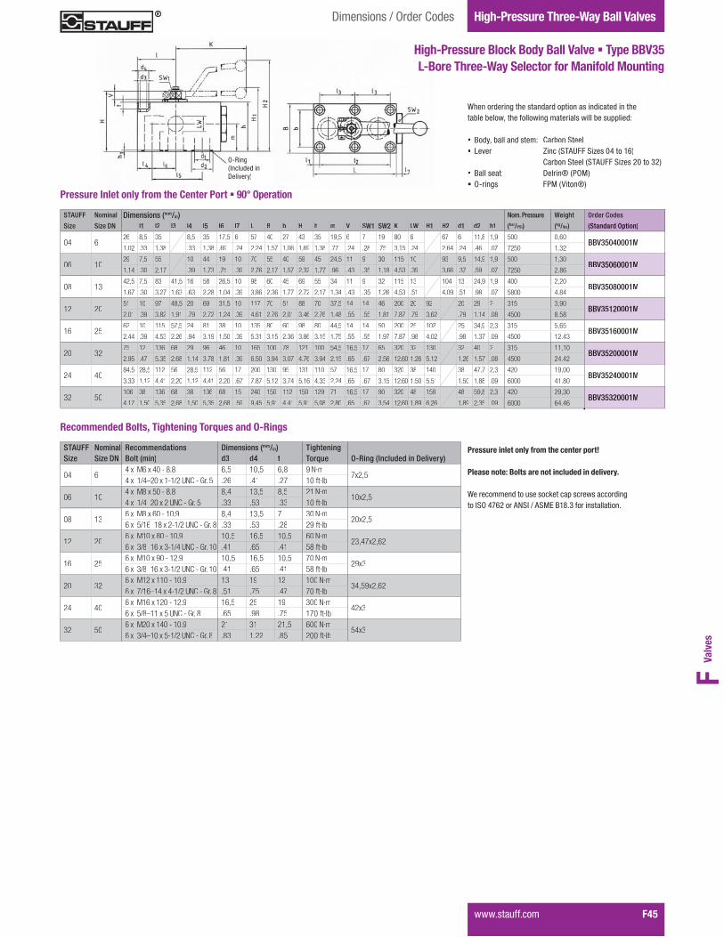
Valv
esF
���� ��&&���� F45
High-Pressure Block Body Ball Valve � Type BBV35 L-Bore Three-Way Selector for Manifold Mounting
Dimensions / Order Codes High-Pressure Three-Way Ball Valves
STAUFF Nominal Dimensions (mm/in) Nom. Pressure Weight Order Codes
Size Size DN l1 l2 l3 l4 l5 l6 l7 L B b H h m V SW1 SW2 K LW H1 H2 d1 d2 h1 (bar/PSI) (kg/lbs) (Standard Option)
04 626 8,5 35 8,5 35 17,5 6 57 40 27 43 35 19,5 6 7 19 80 6 67 6 11,8 1,9 500 0,60
BBV35040001M1.02 .33 1.38 .33 1.38 .69 .24 2.24 1.57 1.06 1.69 1.38 .77 .24 .28 .75 3.15 .24 2.64 .24 .46 .07 7250 1.32
06 1029 7,5 55 10 44 19 10 70 55 40 59 45 24,5 11 9 30 115 10 93 9,5 14,9 1,9 500 1,30
BBV35060001M1.14 .30 2.17 .39 1.73 .75 .39 2.76 2.17 1.57 2.32 1.77 .96 .43 .35 1.18 4.53 .39 3.66 .37 .59 .07 7250 2.86
08 1342,5 7,5 83 41,5 16 58 26,5 10 98 60 45 69 55 34 11 9 32 115 13 104 13 24,9 1,9 400 2,20
BBV35080001M1.67 .30 3.27 1.63 .63 2.28 1.04 .39 3.86 2.36 1.77 2.72 2.17 1.34 .43 .35 1.26 4.53 .51 4.09 .51 .98 .07 5800 4.84
12 2051 10 97 48,5 20 69 31,5 10 117 70 51 88 70 37,5 14 14 46 200 20 92 20 29 2 315 3,90
BBV35120001M2.01 .39 3.82 1.91 .79 2.72 1.24 .39 4.61 2.76 2.01 3.46 2.76 1.48 .55 .55 1.81 7.87 .79 3.62 .79 1.14 .08 4500 8.58
16 2562 10 115 57,5 24 81 38 10 135 80 60 98 80 44,5 14 14 50 200 25 102 25 34,9 2,3 315 5,65
BBV35160001M2.44 .39 4.53 2.26 .94 3.19 1.50 .39 5.31 3.15 2.36 3.86 3.15 1.75 .55 .55 1.97 7.87 .98 4.02 .98 1.37 .09 4500 12.43
20 3275 12 136 68 29 96 46 10 165 100 78 121 100 54,5 16,5 17 65 320 32 130 32 40 2 315 11,10
BBV35200001M2.95 .47 5.35 2.68 1.14 3.78 1.81 .39 6.50 3.94 3.07 4.76 3.94 2.15 .65 .67 2.56 12.60 1.26 5.12 1.26 1.57 .08 4500 24.42
24 4084,5 28,5 112 56 28,5 112 56 17 200 130 95 131 110 57 16,5 17 80 320 38 140 38 47,7 2,3 420 19,00
BBV35240001M3.33 1.12 4.41 2.20 1.12 4.41 2.20 .67 7.87 5.12 3.74 5.16 4.33 2.24 .65 .67 3.15 12.60 1.50 5.51 1.50 1.88 .09 6000 41.80
32 50106 38 136 68 38 136 68 15 240 150 112 150 129 71 16,5 17 90 320 48 159 48 59,8 2,3 420 29,30
BBV35320001M4.17 1.50 5.35 2.68 1.50 5.35 2.68 .59 9.45 5.91 4.41 5.91 5.08 2.80 .65 .67 3.54 12.60 1.89 6.26 1.89 2.35 .09 6000 64.46
Pressure Inlet only from the Center Port � 90° Operation
When ordering the standard option as indicated in the���������{���&�������������� ������ ������!+
� Body, ball and stem: Carbon Steel� Lever: Zinc (STAUFF Sizes 04 to 16)
Carbon Steel (STAUFF Sizes 20 to 32)� Ball seat: Delrin® (POM)� O-rings: FPM (Viton®)
OO-Ring (Included inDelivery)
Pressure inlet only from the center port!
Please note: Bolts are not included in delivery.
|���������!��� � ��w���� ���� ����!�����}?^#~����K�?}�K?_�.�,�4&���� ��������
STAUFF Nominal Recommendations Dimensions (mm/in) TighteningSize Size DN Bolt (min) d3 d4 t Torque O-Ring (Included in Delivery)
04 64 x M6 x 40 - 8.8 6,5 10,5 6,8 9 N·m
7x2,54 x 1/4–20 x 1-1/2 UNC - Gr. 5 .26 .41 .27 10 ft·lb
06 104 x M8 x 50 - 8.8 8,4 13,5 8,5 21 N·m
10x2,54 x 1/4–20 x 2 UNC - Gr. 5 .33 .53 .33 10 ft·lb
08 136 x M8 x 60 - 10.9 8,4 13,5 7 30 N·m
20x2,56 x 5/16–18 x 2-1/2 UNC - Gr. 8 .33 .53 .28 29 ft·lb
12 206 x M10 x 80 - 10.9 10,5 16,5 10,5 60 N·m
23,47x2,626 x 3/8–16 x 3-1/4 UNC - Gr. 10 .41 .65 .41 58 ft·lb
16 256 x M10 x 90 - 12.9 10,5 16,5 10,5 70 N·m
29x36 x 3/8–16 x 3-1/2 UNC - Gr. 10 .41 .65 .41 58 ft·lb
20 326 x M12 x 110 - 10.9 13 19 12 100 N·m
34,59x2,626 x 7/16–14 x 4-1/2 UNC - Gr. 8 .51 .75 .47 70 ft·lb
24 406 x M16 x 120 - 12.9 16,5 25 19 300 N·m
42x36 x 5/8–11 x 5 UNC - Gr. 8 .65 .98 .75 170 ft·lb
32 506 x M20 x 140 - 10.9 21 31 21,5 600 N·m
54x36 x 3/4–10 x 5-1/2 UNC - Gr. 8 .83 1.22 .85 200 ft·lb
#����������$������������������%������&�#����

Gauge Isolator ValvesTwo-Way Ball ValvesHigh-Pressure Three-Way Ball Valves
F46 ���� ��&&����
High-Pressure Block Body Ball Valve � Type BBVS35
Introduction
Options / Accessories� Alternative lever designs/materials (see page F98)� Locking devices (see pages F99-F101)� Pneumatic actuator packages (see page F102)
��������������� ������������� ��� ����� ������ � ����������� Stainless Steel body� Stainless Steel ball and stem� Special ball seat and O-ring materials available for
���������������������� �!�������� �����!�
Porting Pattern� Symbol : LU� Overlap: positive� Operating: 180°
� Stop of end position:
"�� � ����� ���#$���%&������������������������ �
�'�&�*�!�+%~$..3?4%�
Standard Connections Styles / Sizes� Manifold mounting� Either 4 or 6 mounting holes for added safety
(bolts are not included in delivery)
Pressure inlet possible from all ports!See page F113 for sealing details.
Pressure Range� Pressure range: up to 500bar / 7250PSI (depending
on size and material combination of the ball valve)
Temperature Range� Operating temperature range:
$�� <*���=��� <*�$# <� ��� = ��� <�
������������� �������������������������������������������'(��� �������"������������ ���������
Characteristics
Standard Construction� Block body design for manifold mounting � Improved manifold design eliminates
�>������������!��������� � ?������!���������
Standard Materials� Body: Carbon Steel, zinc/iron-plated� Ball: Carbon Steel, hard chrome-plated� Stem: Carbon Steel� Lever: Zinc (STAUFF Sizes 04 to 16)
Carbon Steel (STAUFF Sizes 20 to 32)� Ball seat: Delrin® (POM)� O-rings: FPM (Viton®)
Order Codes
� Type����$"�� ���.���w.�!Q.��3�������Pressure Inlet Possible from all Ports BBVS
� Number of PortsThree Ports (Three-Way Ball Valve) 3
� Connection StyleManifold Mounting 5
"�� ���� ���?JKN��&��������������������� �Q�� �
� Connection Size
"�� ���� ���?JKN��&��������������������� �R� �
� Body Material / Surface FinishingCarbon Steel, zinc/iron-plated 0Stainless Steel V4A (AISI 316Ti) 1
K��������������� � ��&��X�� ���� ����������������� ��*�� ���?JKN��&��&��������&��������
M - - - M M 3 5 08 0 0 0 3 3 5 5 BBVS 08 08 0 0 0 0 0 0 1 1 -
STAUFF Size (according to dimension table):04 06 08 12 16 20 24 32
Pressure inlet possiblefrom all ports!
� Ball / Stem MaterialBall: Carbon Steel, hard chrome-platedStem: Carbon Steel
0
Ball / Stem: Stainless Steel V4A (AISI 316Ti) 1
K��������������� � ��&��X�� ���� ����������������� ��*�� ���?JKN��&��&��������&��������
� Ball Seat MaterialDelrin® (POM) 0PEEK G\�����]�"^_�����?����� ?����Inner Support Ring
H
K��������������� ����������������� ��*�� ���?JKN��&��&��������&��������
O-Ring MaterialNBR (Buna-N®) 0FPM (Viton®) 1EPDM 3
K��������������� ����������������� ��*�� ���?JKN��&��&��������&��������
Manufacturing Code Manufacturing code for all connection styles M
� Lever Options?������!���� ��!�!����������!���������� -?������!������������ -0
K�������������� ������!���! ������Q�"�� � ������q,&��&��������&��������
� Accessories / Options?������!���������� ���� -?������!�������w���\������\� -LD1?������!�������w���\������\#� ��!�!� -LD4?������!����\�����$K�����"�������Actuator (Please add size **)
-EDA**
?������!����?�����$K�����"�������Actuator (Please add size **)
-ESA**
?������!���������?������������� ����� $LS-O?������!���������?���������� �!�� ����� $LS-C?������!���������?������������!closed position -LS-OC
"�� � ������qq&��&��������&��������
No. Qty. Description1 1 Body2* 1 Seats3 2 Ball4* 2 O-Ring5* 2 O-Ring6 2 Retainer Plug7* 2 O-Ring8 1 Stop Pin9 1 Stem10* 1 Thrust Ring11 1 O-Ring12 1 Cam Plate13 1 Snap Ring14 1 *������?����15 1 Handle16 1 Clamping Nut* Included in seal kit
List of Components

Valv
esF
���� ��&&���� F47
High-Pressure Block Body Ball Valve � Type BBVS35 L-Bore Three-Way Selector for Manifold Mounting
Dimensions / Order Codes High-Pressure Three-Way Ball Valves
STAUFF Nominal Dimensions (mm/in) Nom. Pressure Weight Order Codes
Size Size DN l1 l2 l3 l4 l5 l6 l7 L B b H h m V SW1 SW2 K LW H1 H2 d1 d2 h1 (bar/PSI) (kg/lbs) (Standard Option)
04 626 8,5 35 8,5 35 17,5 6 57 40 27 43 35 19,5 6 7 19 80 6 67 6 11,8 1,9 500 0,60
BBVS35040001M1.02 .33 1.38 .33 1.38 .69 .24 2.24 1.57 1.06 1.69 1.38 .77 .24 .28 .75 3.15 .24 2.64 .24 .46 .07 7250 1.32
06 1029 7,5 55 10 44 19 10 70 55 40 59 45 24,5 11 9 30 115 10 93 9,5 14,9 1,9 500 1,30
BBVS35060001M1.14 .30 2.17 .39 1.73 .75 .39 2.76 2.17 1.57 2.32 1.77 .96 .43 .35 1.18 4.53 .39 3.66 .37 .59 .07 7250 2.86
08 1342,5 7,5 83 41,5 16 58 26,5 10 98 60 45 69 55 34 11 9 32 115 13 104 13 24,9 1,9 400 2,20
BBVS35080001M1.67 .30 3.27 1.63 .63 2.28 1.04 .39 3.86 2.36 1.77 2.72 2.17 1.34 .43 .35 1.26 4.53 .51 4.09 .51 .98 .07 5800 4.84
12 2051 10 97 48,5 20 69 31,5 10 117 70 51 88 70 37,5 14 14 46 200 20 92 20 29 2 315 3,90
BBVS35120001M2.01 .39 3.82 1.91 .79 2.72 1.24 .39 4.61 2.76 2.01 3.46 2.76 1.48 .55 .55 1.81 7.87 .79 3.62 .79 1.14 .08 4500 8.58
16 2562 10 115 57,5 24 81 38 10 135 80 60 98 80 44,5 14 14 50 200 25 102 25 34,9 2,3 315 5,65
BBVS35160001M2.44 .39 4.53 2.26 .94 3.19 1.50 .39 5.31 3.15 2.36 3.86 3.15 1.75 .55 .55 1.97 7.87 .98 4.02 .98 1.37 .09 4500 12.43
20 3275 12 136 68 29 96 46 10 165 100 78 121 100 54,5 16,5 17 65 320 32 130 32 40 2 315 11,10
BBVS35200001M2.95 .47 5.35 2.68 1.14 3.78 1.81 .39 6.50 3.94 3.07 4.76 3.94 2.15 .65 .67 2.56 12.60 1.26 5.12 1.26 1.57 .08 4500 24.42
24 4084,5 28,5 112 56 28,5 112 56 17 200 130 95 131 110 57 16,5 17 80 320 38 140 38 47,7 2,3 420 19,00
BBVS35240001M3.33 1.12 4.41 2.20 1.12 4.41 2.20 .67 7.87 5.12 3.74 5.16 4.33 2.24 .65 .67 3.15 12.60 1.50 5.51 1.50 1.88 .09 6000 41.80
32 50106 38 136 68 38 136 68 15 240 150 112 150 129 71 16,5 17 90 320 48 159 48 59,8 2,3 420 29,30
BBVS35320001M4.17 1.50 5.35 2.68 1.50 5.35 2.68 .59 9.45 5.91 4.41 5.91 5.08 2.80 .65 .67 3.54 12.60 1.89 6.26 1.89 2.35 .09 6000 64.46
Pressure Inlet possible from all Ports � 180° Operation
When ordering the standard option as indicated in the���������{���&�������������� ������ ������!+
� Body, ball and stem: Carbon Steel� Lever: Zinc (STAUFF Sizes 04 to 16)
Carbon Steel (STAUFF Sizes 20 to 32)� Ball seat: Delrin® (POM)� O-rings: FPM (Viton®)
OO-Ring (Included inDelivery)
Pressure inlet possible from all ports!Must be operated without pressure!
"�� �����+.��� ����������!�!��!������Q�|���������!��� � ��w���� ���� ����!�����}?^#~����K�?}�K?_�.�,�4&���� ��������
STAUFF Nominal Recommendations Dimensions (mm/in) TighteningSize Size DN Bolt (min) d3 d4 t Torque O-Ring (Included in Delivery)
04 64 x M6 x 40 - 8.8 6,5 10,5 6,8 9 N·m
7x2,54 x 1/4–20 x 1-1/2 UNC - Gr. 5 .26 .41 .27 10 ft·lb
06 104 x M8 x 50 - 8.8 8,4 13,5 8,5 21 N·m
10x2,54 x 1/4–20 x 2 UNC - Gr. 5 .33 .53 .33 10 ft·lb
08 136 x M8 x 60 - 10.9 8,4 13,5 7 30 N·m
20x2,56 x 5/16–18 x 2-1/2 UNC - Gr. 8 .33 .53 .28 29 ft·lb
12 206 x M10 x 80 - 10.9 10,5 16,5 10,5 60 N·m
23,47x2,626 x 3/8–16 x 3-1/4 UNC - Gr. 10 .41 .65 .41 58 ft·lb
16 256 x M10 x 90 - 12.9 10,5 16,5 10,5 70 N·m
29x36 x 3/8–16 x 3-1/2 UNC - Gr. 10 .41 .65 .41 58 ft·lb
20 326 x M12 x 110 - 10.9 13 19 12 100 N·m
34,59x2,626 x 7/16–14 x 4-1/2 UNC - Gr. 8 .51 .75 .47 70 ft·lb
24 406 x M16 x 120 - 12.9 16,5 25 19 300 N·m
42x36 x 5/8–11 x 5 UNC - Gr. 8 .65 .98 .75 170 ft·lb
32 506 x M20 x 140 - 10.9 21 31 21,5 600 N·m
54x36 x 3/4–10 x 5-1/2 UNC - Gr. 8 .83 1.22 .85 200 ft·lb
#����������$������������������%������&�#����

Gauge Isolator ValvesTwo-Way Ball ValvesHigh-Pressure Three-Way Ball Valves
F48 ���� ��&&����
High-Pressure Block Body Ball Valve � Type CBV
Introduction
No. Qty. Description1 1 Body2 1 Stop Pin3* 1 Stem4* 1 Thrust Ring5* 1 Stem O-Ring6* 1 Stem Back Up Ring7 1 Ball8* 2 Ball Seat9 1 Cam Plate10 1 Snap Ring11 2 Connector O-Ring12 2 Connector13 1 Handle14 1 ����}�!�����15 1 Stem Bolt* Included in seal kit
List of Components
1514
1310
96
54
3
27
811
12
1211
8 1
Options / Accessories� Alternative lever designs/materials (see page F98)� Locking devices (see pages F99-F101)� Pneumatic actuator packages (see page F102)
��������������� ������������� ��� ����� ������ � ����������� Stainless Steel body� Stainless Steel ball and stem� Special ball seat and O-ring materials available for
���������������������� �!�������� �����!�� Additional assembling threads (see page F103)
Porting Pattern� Symbol : L� Overlap: negative� Operating: 90°
� Stop of end position:
"�� � ����� ���#$���%&������������������������ �
�'�&�*�!�+%�$*.3�
Standard Connections Styles / Sizes� ������"J����!�K�?}.����������"J� �����.?"����!�\}�}?^��,����.?"� �����N��N������!�?K��%�#���$������N����?K��� �#<���������������\}��4%4�������?���� �4%�� �#<���������������\}��4%4�����Q?���� �4,?
Pressure inlet only from the center port!See page F113 for sealing details.
Pressure Range� Pressure range: up to 500bar / 7250PSI (depending
on size and material combination of the ball valve)
Temperature Range� Operating temperature range:
$�� <*���=��� <*�$# <� ��� = ��� <�
)�� ���������������� �����������+���������������������������������������������������������� �������"������������ ���������
Standard Construction� Block body design for in-line assembly� Compact diverter style� ?������!�����&&$ �������
Standard Materials� Body: Carbon Steel, zinc/iron-plated� Ball: Carbon Steel, hard chrome-plated� Stem: Carbon Steel� Lever: Zinc (STAUFF Sizes 02 to 08)
Carbon Steel (STAUFF Sizes 12 to 32)� Ball seat: Delrin® (POM)� O-rings: FPM (Viton®)
Order Codes
� TypeCompact High-Pressure Block Body Ball Valve CBV
� Number of PortsThree Ports (Three-Way Ball Valve) 3
� Connection Style������"JJ���!�K�?}.������� 0Female BSP Thread (DIN ISO 228) GFemale UN/UNF Thread (SAE J 514) 1
"�� ���� ���?JKN��&��������������������� �Q�� �
� Connection Size
"�� ���� ���?JKN��&��������������������� �R� �
Manufacturing Code MManufacturing code for all connection styles���>����������"JJ���!�
M
Manufacturing code (only for Female NPT Thread) K
� Lever Options?������!���� ��!�!����������!���������� -?������!������������ -0
K�������������� ������!���! ������Q�"�� � ������q,&��&��������&��������
� Accessories / Options?������!���������� ���� -?������!�������w���\������\� -LD1?������!�������w���\������\� -LD2?������!�������w���\������\4 -LD3?������!�������w���\������\#� ��!�!� -LD4?������!����\�����$K�����"�������Actuator (Please add size **)
-EDA**
?������!����?�����$K�����"�������Actuator (Please add size **)
-ESA**
?������!���������?������������� ����� $LS-O?������!���������?���������� �!�� ����� $LS-C?������!���������?������������!closed position -LS-OC
"�� � ������qq&��&��������&��������
Characteristics
STAUFF Size (according to dimension table)for connection styles 0, G and 1:
02 04 06 08 10 12 16 20 24 32
24° Cone Connection (Light / Heavy Series)DN04 DN06 DN08 DN10 DN13 DN16 DN20 DN25
Tube Size (according to dimension table)for 24° Cone Connection (Heavy Series):08S 10S 12S 14S 16S 20S 25S 30S 38S
Tube Size (according to dimension table)for 24° Cone Connection (Light Series):06L 08L 10L 12L 15L 18L 22L 28L 35L
K - - - K K 3 0 02 0 0 0 3 3 0 0 CBV 02 02 0 0 0 0 0 0 1 1 -
Pressurize at center portto avoid internal leakage
� Body Material / Surface FinishingCarbon Steel, zinc/iron-plated 0Stainless Steel V4A (AISI 316Ti) 1
K��������������� � ��&��X�� ���� ����������������� ��*�� ���?JKN��&��&��������&��������
� Ball / Stem MaterialBall: Carbon Steel, hard chrome-platedStem: Carbon Steel
0
Ball / Stem: Stainless Steel V4A (AISI 316Ti) 1
K��������������� � ��&��X�� ���� ����������������� ��*�� ���?JKN��&��&��������&��������
� Ball Seat MaterialDelrin® (POM) 0
K��������������� ����������������� ��*�� ���?JKN��&��&��������&��������
O-Ring MaterialNBR (Buna-N®) 0FPM (Viton®) 1EPDM 3
K��������������� ����������������� ��*�� ���?JKN��&��&��������&��������

Valv
esF
���� ��&&���� F49
Dimensions / Order Codes High-Pressure Three-Way Ball Valves
High-Pressure Block Body Ball Valve � Type CBVL-Bore Three-Way Selector � Female NPT Thread (ANSI B1.20.1)
STAUFF Thread Size NoKinal Dimensions (mm/in) Nom. Pressure Weight Order CodesSize d Size DN LW L l b B H h K S V SW K i H2 (bar/PSI) (kg/lbs) (Standard Option)
02 1/8 NPT 45 69 40 13 29 47 33 13,5 34,5 11 9 115 10,5 82 500 0,40
CBV30020001K.20 2.72 1.57 .51 1.14 1.85 1.30 .53 1.36 .43 .35 4.53 .41 3.23 7250 .88
04 1/4 NPT 66 69 40 13 29 47 33 13,5 34,5 11 9 115 13,7 82 500 0,46
CBV30040001K.24 2.72 1.57 .51 1.14 1.85 1.30 .53 1.36 .43 .35 4.53 .54 3.23 7250 1.01
06 3/8 NPT 1010 72 43 16 35 52 38 17,5 36 11 9 115 13,5 87 500 0,60
CBV30060001K.39 2.83 1.69 .63 1.38 2.05 1.50 .69 1.42 .43 .35 4.53 .53 3.42 7250 1.32
08 1/2 NPT 1313 83 48 17,5 38 54 40 19 41,5 11 9 115 17 89 500 0,70
CBV30080001K.51 3.27 1.89 .69 1.50 2.13 1.57 .75 1.63 .43 .35 4.53 .67 3.50 7250 1.54
12 3/4NPT 2020 95 62 24,5 52 75 57 24,5 47,5 14 14 170 18,3 126 315 1,80
CBV30120001K.79 3.74 2.44 .96 2.05 2.95 2.24 .96 1.87 .55 .55 6.69 .72 4.96 4567 3.96
16 1 NPT 2525 113 66 29 61 83 65 29,5 56,5 14 14 170 21,6 134 315 2,40
CBV30160001K.98 4.45 2.60 1.14 2.40 3.27 2.56 1.16 2.22 .55 .55 6.69 .85 5.73 4567 5.28
20 1-1/4 NPT 3230 120 81 39 106 84,5 39 55 16,5 17 320 22,1 170 350 3,80
CBV30200001K1.18 4.72 3.19 1.54 4.17 3.33 1.54 2.17 .65 .67 12.60 .87 6.69 5075 8.36
24 1-1/2 NPT 4038 140 104 53 127 106 53 65 16,5 17 320 22,1 191 350 6,20
CBV30240001K1.50 5.51 4.09 2.09 5.00 4.17 2.09 2.56 .65 .67 12.60 .87 7.52 5075 13.64
32 2 NPT 5048 150 118 58 116 137 116 58 75 16,5 17 320 30,2 201 350 7,80
CBV30320001K1.89 5.91 4.65 2.28 4.57 5.39 4.57 2.28 2.95 .65 .67 12.60 1.19 7.91 5075 17.16
When ordering the standard option as indicated in the���������{���&�������������� ������ ������!+
� Body, ball and stem: Carbon Steel� Lever: Zinc (STAUFF Sizes 02 to 08)
Carbon Steel (STAUFF Sizes 12 to 32)� Ball seat: Delrin® (POM)� O-rings: FPM (Viton®)
Pressure Inlet only from the Center Port
Female NPT Thread(ANSI B1.20.1)
"�� ����������� �������� �&����������������� �
High-Pressure Block Body Ball Valve � Type CBVL-Bore Three-Way Selector � Female BSP Thread (DIN ISO 228)
STAUFF Thread Size Nominal Dimensions (mm/in) Nom. Pressure Weight Order CodesSize d Size DN L l b B H h m S V SW K i H2 (bar/PSI) (kg/lbs) (Standard Option)
02 G 1/8 BSP 45 69 40 13 29 47 33 13,5 34,5 11 9 115 10 82 500 0,40
CBV3G020001M.20 2.72 1.57 .51 1.14 1.85 1.30 .53 1.36 .43 .35 4.53 .39 3.23 7250 .88
04 G 1/4 BSP 66 69 40 13 29 47 33 13,5 34,5 11 9 115 14 82 500 0,46
CBV3G040001M.24 2.72 1.57 .51 1.14 1.85 1.30 .53 1.36 .43 .35 4.53 .55 3.23 7250 1.01
06 G 3/8 BSP 1010 72 43 16 35 52 38 17,5 36 11 9 115 14 87 500 0,60
CBV3G060001M.39 2.83 1.69 .63 1.38 2.05 1.50 .69 1.42 .43 .35 4.53 .55 3.42 7250 1.32
08 G 1/2 BSP 1313 83 48 17,5 38 54 40 19 41,5 11 9 115 16,3 89 500 0,70
CBV3G080001M.51 3.27 1.89 .69 1.50 2.13 1.57 .75 1.63 .43 .35 4.53 .64 3.50 7250 1.54
12 G 3/4BSP 2020 95 62 24,5 52 75 57 24,5 47,5 14 14 170 18 126 315 1,80
CBV3G120001M.79 3.74 2.44 .96 2.05 2.95 2.24 .96 1.87 .55 .55 6.69 .71 4.96 4567 3.96
16 G 1 BSP 2525 113 66 29 61 83 65 29,5 56,5 14 14 170 20 134 315 2,40
CBV3G160001M.98 4.45 2.60 1.14 2.40 3.27 2.56 1.16 2.22 .55 .55 6.69 .79 5.73 4567 5.28
20 G 1-1/4 BSP 3230 111 81 39 106 84,5 39 55 16,5 17 320 22 170 350 3,80
CBV3G200001M1.18 4.37 3.19 1.54 4.17 3.33 1.54 2.17 .65 .67 12.60 .87 6.69 5075 8.36
24 G 1-1/2 BSP 4038 130 104 53 127 106 53 65 16,5 17 320 24 191 350 6,20
CBV3G240001M1.50 5.12 4.09 2.09 5.00 4.17 2.09 2.56 .65 .67 12.60 .94 7.52 5075 13.64
32 G 2 BSP 5048 150 118 58 116 137 116 58 75 16,5 17 320 26 201 350 7,80
CBV3G320001M1.89 5.91 4.65 2.28 4.57 5.39 4.57 2.28 2.95 .65 .67 12.60 1.02 7.91 5075 17.16
When ordering the standard option as indicated in the���������{���&�������������� ������ ������!+
� Body, ball and stem: Carbon Steel� Lever: Zinc (STAUFF Sizes 02 to 08)
Carbon Steel (STAUFF Sizes 12 to 32)� Ball seat: Delrin® (POM)� O-rings: FPM (Viton®)
Pressure Inlet only from the Center Port
Female BSP ThreadFemale BSP Thread (DIN ISO 228)
"�� ����������� �������� �&����������������� �
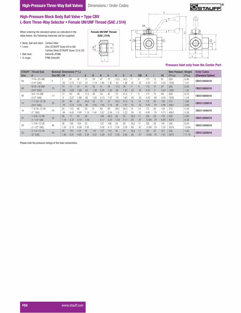
Gauge Isolator ValvesTwo-Way Ball ValvesHigh-Pressure Three-Way Ball Valves
F50 ���� ��&&����
Dimensions / Order Codes
High-Pressure Block Body Ball Valve � Type CBVL-Bore Three-Way Selector � Female UN/UNF Thread (SAE J 514)
STAUFF Thread Size Nominal Dimensions (mm/in) Nom. Pressure Weight Order CodesSize d Size DN L l b B H h K S V SW K i H2 (bar/PSI) (kg/lbs) (Standard Option)
047/16–20 UNF(1/4" SAE)
65 69 40 13 29 47 33 13,5 34,5 11 9 115 12 82 500 0,46
CBV31040001K.20 2.72 1.57 .51 1.14 1.85 1.30 .53 1.36 .43 .35 4.53 .47 3.23 7250 1.01
069/16–18 UNF(3/4" SAE)
1010 72 43 16 35 52 38 17,5 36 11 9 115 13 87 500 0,60
CBV31060001K.39 2.83 1.69 .63 1.38 2.05 1.50 .69 1.42 .43 .35 4.53 .51 3.42 7250 1.32
083/4–16 UNF(1/2" SAE)
1313 83 48 17,5 38 54 40 19 41,5 11 9 115 15 89 500 0,70
CBV31080001K.51 3.27 1.89 .69 1.50 2.13 1.57 .75 1.63 .43 .35 4.53 .59 3.50 7250 1.54
121-1/16–12 UN(3/4" SAE)
2020 95 62 24,5 52 75 57 24,5 47,5 14 14 170 20 126 315 1,80
CBV31120001K.79 3.74 2.44 .96 2.05 2.95 2.24 .96 1.87 .55 .55 6.69 .79 4.96 4567 3.96
161-5/16–12 UN(1" SAE)
2525 113 66 29 61 83 65 29,5 56,5 14 14 170 20 134 315 2,40
CBV31160001K.98 4.45 2.60 1.14 2.40 3.27 2.56 1.16 2.22 .55 .55 6.69 .79 5.73 4567 5.28
201-5/8–12 UN(1-1/4" SAE)
3230 111 81 39 106 84,5 39 55 16,5 17 320 20 170 350 3,80
CBV31200001K1.18 4.37 3.19 1.54 4.17 3.33 1.54 2.17 .65 .67 12.60 .79 6.69 5075 8.36
241-7/8–12 UN(1-1/2" SAE)
4038 130 104 53 127 106 53 65 16,5 17 320 20 191 350 6,20
CBV31240001K1.50 5.12 4.09 2.09 5.00 4.17 2.09 2.56 .65 .67 12.60 .79 7.52 5075 13.64
322-1/2–12 UN(2" SAE)
5048 150 118 58 116 137 116 58 75 16,5 17 320 20 201 350 7,80
CBV31320001K1.89 5.91 4.65 2.28 4.57 5.39 4.57 2.28 2.95 .65 .67 12.60 .79 7.91 5075 17.16
When ordering the standard option as indicated in the ���������{���&�������������� ������ ������!+
� Body, ball and stem: Carbon Steel� Lever: Zinc (STAUFF Sizes 04 to 08)
Carbon Steel (STAUFF Sizes 12 to 32)� Ball seat: Delrin® (POM)� O-rings: FPM (Viton®)
Pressure Inlet only from the Center Port
Female UN/UNF Thread(SAE J 514)
"�� ����������� �������� �&����������������� �

Valv
esF
���� ��&&���� F51
Dimensions / Order Codes High-Pressure Three-Way Ball Valves
High-Pressure Block Body Ball Valve � Type CBVL-Bore Three-Way Selector � 24° Cone Connection
Light Series (DIN 2353 / ISO 8434-1)
High-Pressure Block Body Ball Valve � Type CBVL-Bore Three-Way Selector � 24° Cone Connection
Heavy Series (DIN 2353 / ISO 8434-1)
STAUFF Tube/Thread Size Nominal Dimensions (mm/in) Nom. Pressure Weight Order CodesSize d Size DN RA LW L l b B H h m S V SW K i H2 (bar/PSI) (kg/lbs) (Standard Option)
02 06L / M12 x 1,5 46 5 69 40 13 29 47 33 13,5 34,5 11 9 115 10 82 500 0,30
CBV3DN0406L0001M.24 .20 2.72 1.57 .51 1.14 1.85 1.30 .53 1.36 .43 .35 4.53 .39 3.23 7250 .66
04 08L / M14 x 1,5 68 6 69 40 13 29 47 33 13,5 34,5 11 9 115 10 82 500 0,40
CBV3DN0608L0001M.31 .24 2.72 1.57 .51 1.14 1.85 1.30 .53 1.36 .43 .35 4.53 .39 3.23 7250 .88
05 10L / M16 x 1,5 810 6 69 40 13 29 47 33 13,5 34,5 11 9 115 11 82 500 0,40
CBV3DN0810L0001M.39 .24 2.72 1.57 .51 1.14 1.85 1.30 .53 1.36 .43 .35 4.53 .43 3.23 7250 .88
06 12L / M18 x 1,5 1012 10 72 43 16 35 52 38 17,5 36 11 9 115 11 87 500 0,50
CBV3DN1012L0001M.47 .39 2.83 1.69 .63 1.38 2.05 1.50 .69 1.42 .43 .35 4.53 .43 3.42 7250 1.10
08 15L / M22 x 1,5 1315 13 83 48 17,5 38 54 40 19 41,5 11 9 115 12 89 500 0,65
CBV3DN1315L0001M.59 .51 3.27 1.89 .69 1.50 2.13 1.57 .75 1.63 .43 .35 4.53 .47 3.50 7250 1.43
08 18L / M26 x 1,5 1318 13 83 48 17,5 38 54 40 19 41,5 11 9 115 12 89 500 0,69
CBV3DN1318L0001M.71 .51 3.27 1.89 .69 1.50 2.13 1.57 .75 1.63 .43 .35 4.53 .47 3.50 7250 1.52
12 22L / M30 x 2 2022 20 95 62 24,5 52 75 57 24,5 47,5 14 14 170 14 126 315 1,50
CBV3DN2022L0001M.87 .79 3.74 2.44 .96 2.05 2.95 2.24 .96 1.87 .55 .55 6.69 .55 4.96 4567 3.30
16 28L / M36 x 2 2528 25 113 66 29 61 83 65 29,5 56,5 14 14 170 14 134 315 2,10
CBV3DN2528L0001M1.10 .98 4.45 2.60 1.14 2.40 3.27 2.56 1.16 2.22 .55 .55 6.69 .55 5.73 4567 4.62
16 35L / M45 x 2 25/3235 25 113 66 29 61 83 65 29,5 56,5 14 14 170 16 134 315 2,50
CBV3DN2535L0001M1.38 .98 4.45 2.60 1.14 2.40 3.27 2.56 1.16 2.22 .55 .55 6.69 .63 5.73 4567 5.50
When ordering the standard option as indicated in the���������{���&�������������� ������ ������!+
� Body, ball and stem: Carbon Steel� Lever: Zinc (STAUFF Sizes 02 to 08)
Carbon Steel (STAUFF Sizes 12 to 16)� Ball seat: Delrin® (POM)� O-rings: FPM (Viton®)
Pressure Inlet only from the Center Port
When ordering the standard option as indicated in the���������{���&�������������� ������ ������!+
� Body, ball and stem: Carbon Steel� Lever: Zinc (STAUFF Sizes 02 to 08)
Carbon Steel (STAUFF Sizes 12 to 16)� Ball seat: Delrin® (POM)� O-rings: FPM (Viton®)
Pressure Inlet only from the Center Port
STAUFF Tube/Thread Size Nominal Dimensions (mm/in) Nom. Pressure Weight Order CodesSize d Size DN RA LW L l b B H h m S V SW K i H2 (bar/PSI) (kg/lbs) (Standard Option)
02 08S / M16 x 1,5 48 5 73 40 13 29 47 33 13,5 34,5 11 9 115 12 82 500 0,42
CBV3DN0408S0001M.31 .20 2.87 1.57 .51 1.14 1.85 1.30 .53 1.36 .43 .35 4.53 .47 3.23 7250 .92
04 10S / M18 x 1,5 610 6 73 40 13 29 47 33 13,5 34,5 11 9 115 12 82 500 0,43
CBV3DN0610S0001M.39 .24 2.87 1.57 .51 1.14 1.85 1.30 .53 1.36 .43 .35 4.53 .47 3.23 7250 .95
05 12S / M20 x 1,5 812 6 76 40 13 29 47 33 13,5 34,5 11 9 115 12 82 500 0,44
CBV3DN0812S0001M.47 .24 2.99 1.57 .51 1.14 1.85 1.30 .53 1.36 .43 .35 4.53 .47 3.23 7250 .97
06 14S / M22 x 1,5 1014 10 80 43 16 35 52 38 17,5 36,5 11 9 115 14 87 500 0,50
CBV3DN1014S0001M.55 .39 3.15 1.69 .63 1.38 2.05 1.50 .69 1.43 .43 .35 4.53 .55 3.42 7250 1.10
08 16S / M24 x 1,5 1316 13 86 48 17,5 38 54 40 19 43 11 9 115 14 89 500 0,65
CBV3DN1316S0001M.63 .51 3.39 1.89 .69 1.50 2.13 1.57 .75 1.69 .43 .35 4.53 .55 3.50 7250 1.43
08 20S / M30 x 2 1320 13 90 48 17,5 38 54 40 19 43 11 9 115 16 89 500 0,70
CBV3DN1320S0001M.79 .51 3.54 1.89 .69 1.50 2.13 1.57 .75 1.69 .43 .35 4.53 .63 3.50 7250 1.54
12 25S / M36 x 2 2025 20 109 62 24,5 52 75 57 24,5 48 14 14 170 18 126 315 1,70
CBV3DN2025S0001M.98 .79 4.29 2.44 .96 2.05 2.95 2.24 .96 1.89 .55 .55 6.69 .71 4.96 4567 3.74
16 30S / M42 x 2 2530 25 120 66 29 61 83 65 29,5 57,5 14 14 170 20 134 315 2,40
CBV3DN2530S0001M1.18 .98 4.72 2.60 1.14 2.40 3.27 2.56 1.16 2.26 .55 .55 6.69 .79 5.73 4567 5.28
16 38S / M52 x 2 25/3238 25 124 66 29 61 83 65 29,5 57,5 14 14 170 22 134 315 2,80
CBV3DN2538S0001M1.50 .98 4.88 2.60 1.14 2.40 3.27 2.56 1.16 2.26 .55 .55 6.69 .87 5.73 4567 6.16
24° Cone ConnectionCo e Co ect o(DIN 2353 / ISO 8434-1)DIN 2353 / ISO 8434-1
24° Cone Connection(DDIN 2353 / ISO 8434-1)
��>��� �!����������� ����������!�!��!������Q�
��>��� �!����������� ����������!�!��!������Q�
"�� ����������� �������� �&����������������� �
"�� ����������� �������� �&����������������� �
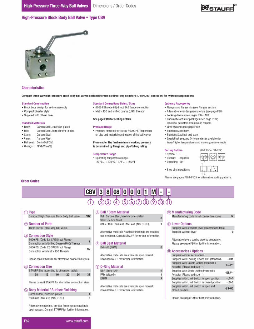
Gauge Isolator ValvesTwo-Way Ball ValvesHigh-Pressure Three-Way Ball Valves
F52 ���� ��&&����
High-Pressure Block Body Ball Valve � Type CBV
Dimensions / Order Codes
Options / Accessories� ����� �!����w�� � ������� �������� Alternative lever designs/materials (see page F98)� Locking devices (see pages F99-F101)� Pneumatic actuator packages (see page F102)
��������������� ������������� ��� ����� ������ � ����������� Stainless Steel body� Stainless Steel ball and stem� Special ball seat and O-ring materials available for
���������������������� �!�������� �����!�
Porting Pattern� Symbol : L� Overlap: negative� Operating: 90°
� Stop of end position:
"�� � ����� ���#$���%&������������������������ �
�'�&�*�!�+%�$*.3�
Standard Connections Styles / Sizes� ����"?}���!����!�����?K���������������� _�����}?^�!���X�!��� ��N�*�����!
See page F113 for sealing details.
Pressure Range� Pressure range: up to 420 bar / 6000 PSI (depending
on size and material combination of the ball valve)
<���������=���>�����?�������+��� ��������������������@������� � �X������������Y
Temperature Range� Operating temperature range:
$��<*���=���<*�$#<����=���<�
)�� ���������������� �����������+���������������������������������������������������������� �������"������������ ���������
Standard Construction� Block body design for in-line assembly� Compact diverter style� ?������!�����&&$ �������
Standard Materials� Body: Carbon Steel, zinc/iron-plated� Ball: Carbon Steel, hard chrome-plated� Stem: Carbon Steel� Lever: Carbon Steel� Ball seat: Delrin® (POM)� O-rings: FPM (Viton®)
Order Codes
� Type Compact High-Pressure Block Body Ball Valve CBV
� Number of Ports Three Ports (Three-Way Ball Valve) 3
� Connection Style 6000 PSI (Code 62) SAE Direct Flange *�������������N��X�!*�� ��N�*�J���!
8
6000 PSI (Code 62) SAE Direct Flange *�������������_�����}?^J���!
8M
"�� ���� ���?JKN��&��������������������� �Q�� �
� Connection Size
"�� ���� ���?JKN��&��������������������� �R� �
� Body Material / Surface Finishing Carbon Steel, zinc/iron-plated 0 Stainless Steel V4A (AISI 316Ti) 1
K��������������� � ��&��X�� ���� �������� ��������� ��*�� ���?JKN��&��&��������&��������
Manufacturing Code MManufacturing code for all connection styles M
� Lever Options?������!���� ��!�!����������!���������� -?������!������������ -0
K�������������� ������!���! ������Q�"�� � ������q,&��&��������&��������
� Accessories / Options?������!���������� ���� -?������!�������w���\������\�� ��!�!� -LD1?������!����\�����$K�����"�������Actuator (Please add size **)
-EDA**
?������!����?�����$K�����"�������Actuator (Please add size **)
-ESA**
?������!���������?������������� ����� $LS-O?������!���������?���������� �!�� ����� $LS-C?������!���������?������������!closed position -LS-OC
"�� � ������qq&��&��������&��������
Characteristics
M - - - M M 3 8 08 0 0 0 3 3 8 8 CBV 08 08 0 0 0 0 0 0 1 1 -
STAUFF Size (according to dimension table):08 12 16 20 24 32
� Ball / Stem Material Ball: Carbon Steel, hard chrome-plated Stem: Carbon Steel
0
Ball / Stem: Stainless Steel V4A (AISI 316Ti) 1
K��������������� � ��&��X�� ���� �������� ��������� ��*�� ���?JKN��&��&��������&��������
� Ball Seat Material Delrin® (POM) 0
K��������������� ����������������� �� *�� ���?JKN��&��&��������&��������
O-Ring Material NBR (Buna-N®) 0 FPM (Viton®) 1 EPDM 3
K��������������� ����������������� �� *�� ���?JKN��&��&��������&��������
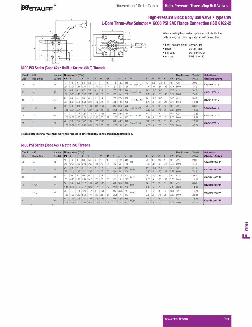
Valv
esF
���� ��&&���� F53
Dimensions / Order Codes High-Pressure Three-Way Ball Valves
High-Pressure Block Body Ball Valve � Type CBVL-Bore Three-Way Selector � 6000 PSI SAE Flange Connection (ISO 6162-2)
When ordering the standard option as indicated in the���������{���&�������������� ������ ������!+
� Body, ball and stem: Carbon Steel� Lever: Carbon Steel� Ball seat: Delrin® (POM)� O-rings: FPM (Viton®)
<���������=���>�����?�������+��� ��������������������@������� � �X������������Y
6000 PSI Series (Code 62) � Z��>��)������Z[)"�������
STAUFF SAE Nominal Dimensions (mm/in) Nom. Pressure Weight Order Codes
Size Flange Size Size DN L B H h m V SW K a b M G d1 d2 t H2 (bar/PSI) (kg/lbs) (Standard Option)
08 1/2 1313 70 70 63 56 28 11 9 115 18,2 40,5
5/16–18 UNC43 8,5 13,5 9 101 420 2,00
CBV38080001M.51 2.76 2.76 2.48 2.20 1.10 .43 .35 4.53 .72 1.59 1.69 .33 .53 .35 3.98 6000 4.40
12 3/4 2020 80 80 87 72 36 14 14 170 23,8 50,8
3/8–16 UNC60 10,5 16,5 11 137 420 3,40
CBV38120001M.79 3.15 3.15 3.43 2.83 1.42 .55 .55 6.69 .94 2.00 2.36 .41 .65 .43 5.39 6000 7.48
16 1 2525 94 94 96 81 42 14 14 170 27,8 57,2
7/16–14 UNC70 10,5 16,5 11 147 420 5,40
CBV38160001M.98 3.70 3.70 3.78 3.19 1.65 .55 .55 6.69 1.09 2.25 2.76 .41 .65 .43 5.79 6000 11.88
20 1-1/4 3230 100 100 117 100 50,5 16,5 17 306 31,8 66,6
1/2–13 UNC76 13 19 13 181 420 6,80
CBV38200001M1.18 3.94 3.94 4.61 3.94 1.99 .65 .67 12.05 1.25 2.62 2.99 .51 .75 .51 7.13 6000 14.96
24 1-1/2 4038 110 110 129 112 55 16,5 17 306 36,5 79,4
5/8–11 UNC84 13 19 13 193 420 10,20
CBV38240001M1.50 4.33 4.33 5.08 4.41 2.17 .65 .67 12.05 1.44 3.13 3.31 .51 .75 .51 7.60 6000 22.44
32 2 5048 135 135 147 135 67,5 16,5 17 306 44,5 96,8
3/4–10 UNC108 13 19 13 211 420 18,50
CBV38320001M1.89 5.31 5.31 5.79 5.31 2.66 .65 .67 12.05 1.75 3.81 4.25 .51 .75 .51 8.31 6000 40.70
6000 PSI Series (Code 62) � Metric ISO Threads
STAUFF SAE Nominal Dimensions (mm/in) Nom. Pressure Weight Order Codes
Size Flange Size Size DN L B H h m V SW K a b M G d1 d2 t H2 (bar/PSI) (kg/lbs) (Standard Option)
08 1/2 1313 70 70 63 56 28 11 9 115 18,2 40,5
M843 8,5 13,5 9 101 420 2,00
CBV38M080001M.51 2.76 2.76 2.48 2.20 1.10 .43 .35 4.53 .72 1.59 1.69 .33 .53 .35 3.98 6000 4.40
12 3/4 2020 80 80 87 72 36 14 14 170 23,8 50,8
M1060 10,5 16,5 11 137 420 3,40
CBV38M120001M.79 3.15 3.15 3.43 2.83 1.42 .55 .55 6.69 .94 2.00 2.36 .41 .65 .43 5.39 6000 7.48
16 1 2525 94 94 96 81 42 14 14 170 27,8 57,2
M1270 10,5 16,5 11 147 420 5,40
CBV38M160001M.98 3.70 3.70 3.78 3.19 1.65 .55 .55 6.69 1.09 2.25 2.76 .41 .65 .43 5.79 6000 11.88
20 1-1/4 3230 100 100 117 100 50,5 16,5 17 306 31,8 66,6
M1276 13 19 13 181 420 6,80
CBV38M200001M1.18 3.94 3.94 4.61 3.94 1.99 .65 .67 12.05 1.25 2.62 2.99 .51 .75 .51 7.13 6000 14.96
24 1-1/2 4038 110 110 129 112 55 16,5 17 306 36,5 79,4
M1684 13 19 13 193 420 10,20
CBV38M240001M1.50 4.33 4.33 5.08 4.41 2.17 .65 .67 12.05 1.44 3.13 3.31 .51 .75 .51 7.60 6000 22.44
32 2 5048 135 135 147 135 67,5 16,5 17 306 44,5 96,8
M20108 13 19 13 211 420 18,50
CBV38M320001M1.89 5.31 5.31 5.79 5.31 2.66 .65 .67 12.05 1.75 3.81 4.25 .51 .75 .51 8.31 6000 40.70
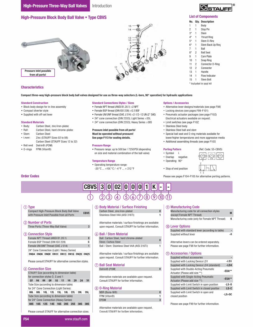
Gauge Isolator ValvesTwo-Way Ball ValvesHigh-Pressure Three-Way Ball Valves
F54 ���� ��&&����
High-Pressure Block Body Ball Valve � Type CBVS
Introduction
Options / Accessories� Alternative lever designs/materials (see page F98)� Locking devices (see pages F99-F101)� Pneumatic actuator packages (see page F102)
��������������� ������������� ��� ����� ������ � ����������� Stainless Steel body� Stainless Steel ball and stem� Special ball seat and O-ring materials available for
���������������������� �!�������� �����!�� Additional assembling threads (see page F103)
Porting Pattern� Symbol : L� Overlap: negative � Operating: 90°
� Stop of end position:
"�� � ����� ���#$���%&������������������������ �
Standard Connections Styles / Sizes� ������"J����!�K�?}.����������"J� �����.?"����!�\}�}?^��,����.?"� �����N��N������!�?K��%�#���$������N����?K��� �#<���������������\}��4%4�������?���� �4%�� �#<���������������\}��4%4�����Q?���� �4,?
Pressure inlet possible from all ports! Must be operated without pressure!See page F113 for sealing details.
Pressure Range� Pressure range: up to 500bar / 7250PSI (depending
on size and material combination of the ball valve)
Temperature Range� Operating temperature range:
$�� <*���=��� <*�$# <� ��� = ��� <�
)�� ���������������� �����������+���������������������������������������������������������� �������"������������ ���������
Standard Construction� Block body design for in-line assembly� Compact diverter style� ?������!�����&&$ �������
Standard Materials� Body: Carbon Steel, zinc/iron-plated� Ball: Carbon Steel, hard chrome-plated� Stem: Carbon Steel� Lever: Zinc (STAUFF Sizes 02 to 08)
Carbon Steel (STAUFF Sizes 12 to 32)� Ball seat: Delrin® (POM)� O-rings: FPM (Viton®)
Order Codes
Manufacturing Code MManufacturing code for all connection styles���>����������"JJ���!�
M
Manufacturing code (only for Female NPT Thread) K
� Lever Options?������!���� ��!�!����������!���������� -?������!������������ -0
K�������������� ������!���! ������Q�"�� � ������q,&��&��������&��������
� Accessories / Options?������!���������� ���� -?������!�������w���\������\� -LD1?������!�������w���\������\#� ��!�!� -LD4?������!����\�����$K�����"�������Actuator (Please add size **)
-EDA**
?������!����?�����$K�����"�������Actuator (Please add size **)
-ESA**
?������!���������?������������� ����� $LS-O?������!���������?���������� �!�� ����� $LS-C?������!���������?������������!closed position -LS-OC
"�� � ������qq&��&��������&��������
Characteristics
K - - - K K 3 0 02 0 0 0 3 3 0 0 CBVS 02 02 0 0 0 0 0 0 1 1 -
No. Qty. Description1 1 Body2 1 Stop Pin3* 1 Stem4* 1 Thrust Ring5* 1 Stem O-Ring6* 1 Stem Back Up Ring7 1 Ball8* 2 Ball Seat9 1 Cam Plate10 1 Snap Ring11 2 Connector O-Ring12 2 Connector13 1 Handle14 1 ����}�!�����15 1 Stem Bolt* Included in seal kit
List of Components
1514
1310
96
54
3
27
811
12
1211
8 1
�'�&�*�!�+%%$*.3?�
Pressure inlet possiblefrom all ports!
� TypeCompact High-Pressure Block Body Ball Valve ����"�� ���}����"� ����&�����"���
CBVS
� Number of PortsThree Ports (Three-Way Ball Valve) 3
� Connection Style������"JJ���!�K�?}.������� 0Female BSP Thread (DIN ISO 228) GFemale UN/UNF Thread (SAE J 514) 1
"�� ���� ���?JKN��&��������������������� �Q�� �
� Connection Size
"�� ���� ���?JKN��&��������������������� �R� �
STAUFF Size (according to dimension table)for connection styles O, G and 1:
02 04 06 08 10 12 16 20 24 32
24° Cone Connection (Light / Heavy Series)DN04 DN06 DN08 DN10 DN13 DN16 DN20 DN25
Tube Size (according to dimension table)for 24° Cone Connection (Heavy Series):08S 10S 12S 14S 16S 20S 25S 30S 38S
Tube Size (according to dimension table)for 24° Cone Connection (Light Series):06L 08L 10L 12L 15L 18L 22L 28L 35L
� Body Material / Surface FinishingCarbon Steel, zinc/iron-plated 0Stainless Steel V4A (AISI 316Ti) 1
K��������������� � ��&��X�� ���� ����������������� ��*�� ���?JKN��&��&��������&��������
� Ball / Stem Material Ball: Carbon Steel, hard chrome-plated
Stem: Carbon Steel0
Ball / Stem: Stainless Steel V4A (AISI 316Ti) 1
K��������������� � ��&��X�� ���� ����������������� ��*�� ���?JKN��&��&��������&��������
� Ball Seat MaterialDelrin® (POM) 0
K��������������� ����������������� ��*�� ���?JKN��&��&��������&��������
O-Ring MaterialNBR (Buna-N®) 0FPM (Viton®) 1EPDM 3
K��������������� ����������������� ��*�� ���?JKN��&��&��������&��������

Valv
esF
���� ��&&���� F55
Dimensions / Order Codes High-Pressure Three-Way Ball Valves
High-Pressure Block Body Ball Valve � Type CBVSL-Bore Three-Way Selector � Female NPT Thread (ANSI B1.20.1)
STAUFF Thread Size Nominal Dimensions (mm/in) Nom. Pressure Weight Order CodesSize d Size DN LW L l b B H h K S V SW K i H2 (bar/PSI) (kg/lbs) (Standard Option)
02 1/8 NPT 45 69 40 13 29 47 33 13,5 34,5 11 9 115 10,5 82 500 0,40
CBVS30020001K.20 2.72 1.57 .51 1.14 1.85 1.30 .53 1.36 .43 .35 4.53 .41 3.23 7250 .88
04 1/4 NPT 66 69 40 13 29 47 33 13,5 34,5 11 9 115 13,7 82 500 0,46
CBVS30040001K.24 2.72 1.57 .51 1.14 1.85 1.30 .53 1.36 .43 .35 4.53 .54 3.23 7250 1.01
06 3/8 NPT 1010 72 43 16 35 52 38 17,5 36 11 9 115 13,5 87 500 0,60
CBVS30060001K.39 2.83 1.69 .63 1.38 2.05 1.50 .69 1.42 .43 .35 4.53 .53 3.42 7250 1.32
08 1/2 NPT 1313 83 48 17,5 38 54 40 19 41,5 11 9 115 17 89 500 0,70
CBVS30080001K.51 3.27 1.89 .69 1.50 2.13 1.57 .75 1.63 .43 .35 4.53 .67 3.50 7250 1.54
12 3/4NPT 2020 95 62 24,5 52 75 57 24,5 47,5 14 14 170 18,3 126 315 1,80
CBVS30120001K.79 3.74 2.44 .96 2.05 2.95 2.24 .96 1.87 .55 .55 6.69 .72 4.96 4567 3.96
16 1 NPT 2525 113 66 29 61 83 65 29,5 56,5 14 14 170 21,6 134 315 2,40
CBVS30160001K.98 4.45 2.60 1.14 2.40 3.27 2.56 1.16 2.22 .55 .55 6.69 .85 5.73 4567 5.28
20 1-1/4 NPT 3230 120 81 39 106 84,5 39 55 16,5 17 320 22,1 170 350 3,80
CBVS30200001K1.18 4.72 3.19 1.54 4.17 3.33 1.54 2.17 .65 .67 12.60 .87 6.69 5075 8.36
24 1-1/2 NPT 4038 140 104 53 127 106 53 65 16,5 17 320 22,1 191 350 6,20
CBVS30240001K1.50 5.51 4.09 2.09 5.00 4.17 2.09 2.56 .65 .67 12.60 .87 7.52 5075 13.64
32 2 NPT 5048 150 118 58 116 137 116 58 75 16,5 17 320 30,2 201 350 7,80
CBVS30320001K1.89 5.91 4.65 2.28 4.57 5.39 4.57 2.28 2.95 .65 .67 12.60 1.19 7.91 5075 17.16
Pressure Inlet possible from all Ports
Female NPT Threade a e ea(ANSI B1.20.1)
When ordering the standard option as indicated in the���������{���&�������������� ������ ������!+
� Body, ball and stem: Carbon Steel� Lever: Zinc (STAUFF Sizes 02 to 08)
Carbon Steel (STAUFF Sizes 12 to 32)� Ball seat: Delrin® (POM)� O-rings: FPM (Viton®)
"�� ����������� �������� �&����������������� �
High-Pressure Block Body Ball Valve � Type CBVSL-Bore Three-Way Selector � Female BSP Thread (DIN ISO 228)
STAUFF Thread Size Nominal Dimensions (mm/in) Nom. Pressure Weight Order CodesSize d Size DN L l b B H h m S V SW K i H2 (bar/PSI) (kg/lbs) (Standard Option)
02 G 1/8 BSP 45 69 40 13 29 47 33 13,5 34,5 11 9 115 10 82 500 0,40
CBVS3G020001M.20 2.72 1.57 .51 1.14 1.85 1.30 .53 1.36 .43 .35 4.53 .39 3.23 7250 .88
04 G 1/4 BSP 66 69 40 13 29 47 33 13,5 34,5 11 9 115 14 82 500 0,46
CBVS3G040001M.24 2.72 1.57 .51 1.14 1.85 1.30 .53 1.36 .43 .35 4.53 .55 3.23 7250 1.01
06 G 3/8 BSP 1010 72 43 16 35 52 38 17,5 36 11 9 115 14 87 500 0,60
CBVS3G060001M.39 2.83 1.69 .63 1.38 2.05 1.50 .69 1.42 .43 .35 4.53 .55 3.42 7250 1.32
08 G 1/2 BSP 1313 83 48 17,5 38 54 40 19 41,5 11 9 115 16,3 89 500 0,70
CBVS3G080001M.51 3.27 1.89 .69 1.50 2.13 1.57 .75 1.63 .43 .35 4.53 .64 3.50 7250 1.54
12 G 3/4BSP 2020 95 62 24,5 52 75 57 24,5 47,5 14 14 170 18 126 315 1,80
CBVS3G120001M.79 3.74 2.44 .96 2.05 2.95 2.24 .96 1.87 .55 .55 6.69 .71 4.96 4567 3.96
16 G 1 BSP 2525 113 66 29 61 83 65 29,5 56,5 14 14 170 20 134 315 2,40
CBVS3G160001M.98 4.45 2.60 1.14 2.40 3.27 2.56 1.16 2.22 .55 .55 6.69 .79 5.73 4567 5.28
20 G 1-1/4 BSP 3230 111 81 39 106 84,5 39 55 16,5 17 320 22 170 350 3,80
CBVS3G200001M1.18 4.37 3.19 1.54 4.17 3.33 1.54 2.17 .65 .67 12.60 .87 6.69 5075 8.36
24 G 1-1/2 BSP 4038 130 104 53 127 106 53 65 16,5 17 320 24 191 350 6,20
CBVS3G240001M1.50 5.12 4.09 2.09 5.00 4.17 2.09 2.56 .65 .67 12.60 .94 7.52 5075 13.64
32 G 2 BSP 5048 150 118 58 116 137 116 58 75 16,5 17 320 26 201 350 7,80
CBVS3G320001M1.89 5.91 4.65 2.28 4.57 5.39 4.57 2.28 2.95 .65 .67 12.60 1.02 7.91 5075 17.16
Pressure Inlet possible from all Ports
Female BSP ThreadFemale BSP Thread (DIN ISO 228)
When ordering the standard option as indicated in the���������{���&�������������� ������ ������!+
� Body, ball and stem: Carbon Steel� Lever: Zinc (STAUFF Sizes 02 to 08)
Carbon Steel (STAUFF Sizes 12 to 32)� Ball seat: Delrin® (POM)� O-rings: FPM (Viton®)
"�� ����������� �������� �&����������������� �

Gauge Isolator ValvesTwo-Way Ball ValvesHigh-Pressure Three-Way Ball Valves
F56 ���� ��&&����
Dimensions / Order Codes
High-Pressure Block Body Ball Valve � Type CBVSL-Bore Three-Way Selector � Female UN/UNF Thread (SAE J 514)
STAUFF Thread Size Nominal Dimensions (mm/in) Nom. Pressure Weight Order CodesSize d Size DN L l b B H h K S V SW K i H2 (bar/PSI) (kg/lbs) (Standard Option)
047/16–20 UNF(1/4" SAE)
65 69 40 13 29 47 33 13,5 34,5 11 9 115 12 82 500 0,46
CBVS31040001M.20 2.72 1.57 .51 1.14 1.85 1.30 .53 1.36 .43 .35 4.53 .47 3.23 7250 1.01
069/16–18 UNF(3/8" SAE)
1010 72 43 16 35 52 38 17,5 36 11 9 115 13 87 500 0,60
CBVS31060001M.39 2.83 1.69 .63 1.38 2.05 1.50 .69 1.42 .43 .35 4.53 .51 3.42 7250 1.32
083/4–16 UNF(1/2" SAE)
1313 83 48 17,5 38 54 40 19 41,5 11 9 115 15 89 500 0,70
CBVS31080001M.51 3.27 1.89 .69 1.50 2.13 1.57 .75 1.63 .43 .35 4.53 .59 3.50 7250 1.54
121-1/16–12 UN(3/4" SAE)
2020 95 62 24,5 52 75 57 24,5 47,5 14 14 170 20 126 315 1,80
CBVS31120001M.79 3.74 2.44 .96 2.05 2.95 2.24 .96 1.87 .55 .55 6.69 .79 4.96 4567 3.96
161-5/16–12 UN(1" SAE)
2525 113 66 29 61 83 65 29,5 56,5 14 14 170 20 134 315 2,40
CBVS31160001M.98 4.45 2.60 1.14 2.40 3.27 2.56 1.16 2.22 .55 .55 6.69 .79 5.73 4567 5.28
201-5/8–12 UN(1-1/4" SAE)
3230 111 81 39 106 84,5 39 55 16,5 17 320 20 170 350 3,80
CBVS31200001M1.18 4.37 3.19 1.54 4.17 3.33 1.54 2.17 .65 .67 12.60 .79 6.69 5075 8.36
241-7/8–12 UN(1-1/2" SAE)
4038 130 104 53 127 106 53 65 16,5 17 320 20 191 350 6,20
CBVS31240001M1.50 5.12 4.09 2.09 5.00 4.17 2.09 2.56 .65 .67 12.60 .79 7.52 5075 13.64
322-1/2–12 UN(2" SAE)
5048 150 118 58 116 137 116 58 75 16,5 17 320 20 201 350 7,80
CBVS31320001M1.89 5.91 4.65 2.28 4.57 5.39 4.57 2.28 2.95 .65 .67 12.60 .79 7.91 5075 17.16
Pressure Inlet possible from all Ports
Female UN/UNF Thread(SAE J 514)
When ordering the standard option as indicated in the���������{���&�������������� ������ ������!+
� Body, ball and stem: Carbon Steel� Lever: Zinc (STAUFF Sizes 04 to 08)
Carbon Steel (STAUFF Sizes 12 to 32)� Ball seat: Delrin® (POM)� O-rings: FPM (Viton®)
"�� ����������� �������� �&����������������� �

Valv
esF
���� ��&&���� F57
Dimensions / Order Codes High-Pressure Three-Way Ball Valves
High-Pressure Block Body Ball Valve � Type CBVSL-Bore Three-Way Selector � 24° Cone Connection
Light Series (DIN 2353 / ISO 8434-1)
High-Pressure Block Body Ball Valve � Type CBVSL-Bore Three-Way Selector � 24° Cone Connection
Heavy Series (DIN 2353 / ISO 8434-1)
STAUFF Tube/Thread Size Nominal Dimensions (mm/in) Nom. Pressure Weight Order CodesSize d Size DN RA LW L l b B H h m S V SW K i H2 (bar/PSI) (kg/lbs) (Standard Option)
02 06L / M12 x 1,5 46 5 69 40 13 29 47 33 13,5 34,5 11 9 115 10 82 500 0,30
CBVS3DN0406L0001M.24 .20 2.72 1.57 .51 1.14 1.85 1.30 .53 1.36 .43 .35 4.53 .39 3.23 7250 .66
04 08L / M14 x 1,5 68 6 69 40 13 29 47 33 13,5 34,5 11 9 115 10 82 500 0,40
CBVS3DN0608L0001M.31 .24 2.72 1.57 .51 1.14 1.85 1.30 .53 1.36 .43 .35 4.53 .39 3.23 7250 .88
05 10L / M16 x 1,5 810 6 69 40 13 29 47 33 13,5 34,5 11 9 115 11 82 500 0,40
CBVS3DN0810L0001M.39 .24 2.72 1.57 .51 1.14 1.85 1.30 .53 1.36 .43 .35 4.53 .43 3.23 7250 .88
06 12L / M18 x 1,5 1012 10 72 43 16 35 52 38 17,5 36 11 9 115 11 87 500 0,50
CBVS3DN1012L0001M.47 .39 2.83 1.69 .63 1.38 2.05 1.50 .69 1.42 .43 .35 4.53 .43 3.42 7250 1.10
08 15L / M22 x 1,5 1315 13 83 48 17,5 38 54 40 19 41,5 11 9 115 12 89 500 0,65
CBVS3DN1315L0001M.59 .51 3.27 1.89 .69 1.50 2.13 1.57 .75 1.63 .43 .35 4.53 .47 3.50 7250 1.43
08 18L / M26 x 1,5 1318 13 83 48 17,5 38 54 40 19 41,5 11 9 115 12 89 500 0,69
CBVS3DN1318L0001M.71 .51 3.27 1.89 .69 1.50 2.13 1.57 .75 1.63 .43 .35 4.53 .47 3.50 7250 1.52
12 22L / M30 x 2 2022 20 95 62 24,5 52 75 57 24,5 47,5 14 14 170 14 126 315 1,50
CBVS3DN2022L0001M.87 .79 3.74 2.44 .96 2.05 2.95 2.24 .96 1.87 .55 .55 6.69 .55 4.96 4567 3.30
16 28L / M36 x 2 2528 25 113 66 29 61 83 65 29,5 56,5 14 14 170 14 134 315 2,10
CBVS3DN2528L0001M1.10 .98 4.45 2.60 1.14 2.40 3.27 2.56 1.16 2.22 .55 .55 6.69 .55 5.73 4567 4.62
16 35L / M45 x 2 25/3235 25 113 66 29 61 83 65 29,5 56,5 14 14 170 16 134 315 2,50
CBVS3DN2535L0001M1.38 .98 4.45 2.60 1.14 2.40 3.27 2.56 1.16 2.22 .55 .55 6.69 .63 5.73 4567 5.50
Pressure Inlet possible from all Ports
Pressure Inlet possible from all Ports
STAUFF Tube/Thread Size Nominal Dimensions (mm/in) Nom. Pressure Weight Order CodesSize d Size DN RA LW L l b B H h m S V SW K i H2 (bar/PSI) (kg/lbs) (Standard Option)
02 08S / M16 x 1,5 48 5 73 40 13 29 47 33 13,5 34,5 11 9 115 12 82 500 0,42
CBVS3DN0408S0001M.31 .20 2.87 1.57 .51 1.14 1.85 1.30 .53 1.36 .43 .35 4.53 .47 3.23 7250 .92
04 10S / M18 x 1,5 610 6 73 40 13 29 47 33 13,5 34,5 11 9 115 12 82 500 0,43
CBVS3DN0610S0001M.39 .24 2.87 1.57 .51 1.14 1.85 1.30 .53 1.36 .43 .35 4.53 .47 3.23 7250 .95
05 12S / M20 x 1,5 812 6 76 40 13 29 47 33 13,5 34,5 11 9 115 12 82 500 0,44
CBVS3DN0812S0001M.47 .24 2.99 1.57 .51 1.14 1.85 1.30 .53 1.36 .43 .35 4.53 .47 3.23 7250 .97
06 14S / M22 x 1,5 1014 10 80 43 16 35 52 38 17,5 36,5 11 9 115 14 87 500 0,50
CBVS3DN1014S0001M.55 .39 3.15 1.69 .63 1.38 2.05 1.50 .69 1.43 .43 .35 4.53 .55 3.42 7250 1.10
08 16S / M24 x 1,5 1316 13 86 48 17,5 38 54 40 19 43 11 9 115 14 89 500 0,65
CBVS3DN1316S0001M.63 .51 3.39 1.89 .69 1.50 2.13 1.57 .75 1.69 .43 .35 4.53 .55 3.50 7250 1.43
08 20S / M30 x 2 1320 13 90 48 17,5 38 54 40 19 43 11 9 115 16 89 500 0,70
CBVS3DN1320S0001M.79 .51 3.54 1.89 .69 1.50 2.13 1.57 .75 1.69 .43 .35 4.53 .63 3.50 7250 1.54
12 25S / M36 x 2 2025 20 109 62 24,5 52 75 57 24,5 48 14 14 170 18 126 315 1,70
CBVS3DN2025S0001M.98 .79 4.29 2.44 .96 2.05 2.95 2.24 .96 1.89 .55 .55 6.69 .71 4.96 4567 3.74
16 30S / M42 x 2 2530 25 120 66 29 61 83 65 29,5 57,5 14 14 170 20 134 315 2,40
CBVS3DN2530S0001M1.18 .98 4.72 2.60 1.14 2.40 3.27 2.56 1.16 2.26 .55 .55 6.69 .79 5.73 4567 5.28
16 38S / M52 x 2 25/3238 25 124 66 29 61 83 65 29,5 57,5 14 14 170 22 134 315 2,80
CBVS3DN2538S0001M1.50 .98 4.88 2.60 1.14 2.40 3.27 2.56 1.16 2.26 .55 .55 6.69 .87 5.73 4567 6.16
24° Cone ConnectionCo e Co ect o(DIN 2353 / ISO 8434-1)DIN 2353 / ISO 8434-1
24° Cone Connection(DDIN 2353 / ISO 8434-1)
��>��� �!����������� ����������!�!��!������Q�
��>��� �!����������� ����������!�!��!������Q�
When ordering the standard option as indicated in the���������{���&�������������� ������ ������!+
� Body, ball and stem: Carbon Steel� Lever: Zinc (STAUFF Sizes 02 to 08)
Carbon Steel (STAUFF Sizes 12 to 16)� Ball seat: Delrin® (POM)� O-rings: FPM (Viton®)
When ordering the standard option as indicated in the ���������{���&�������������� ������ ������!+
� Body, ball and stem: Carbon Steel� Lever: Zinc (STAUFF Sizes 02 to 08)
Carbon Steel (STAUFF Sizes 12 to 16)� Ball seat: Delrin® (POM)� O-rings: FPM (Viton®)
"�� ����������� �������� �&����������������� �
"�� ����������� �������� �&����������������� �

Gauge Isolator ValvesTwo-Way Ball ValvesHigh-Pressure Three-Way Ball Valves
F58 ���� ��&&����
High-Pressure Block Body Ball Valve � Type LBV
Introduction
No. Qty. Description1 1 Body2 1 Stop Pin3* 2 Bearing4 1 Trunnion Retainer5* 2 Trunnion O-Ring6* 1 Retainer O-Ring7* 3 Ball Seat8* 3 Seat O-Ring9* 3 Connector O-Ring10 1 Cam Plate11 1 Snap Ring12* 2 Trunnion Back Up Ring13 3 Seat Support14 1 Trunnion Ball15 3 Connector16 1 Handle17 1 Handle Bolt* Included in seal kit
List of Components
Options / Accessories� Alternative lever designs/materials (see page F98)� Locking devices (see pages F99-F101)� Pneumatic actuator packages (see page F102)
��������������� ������������� ��� ����� ������ � ����������� Stainless Steel body� Stainless Steel ball and stem� Special ball seat and O-ring materials available for
���������������������� �!�������� �����!�
Porting Pattern� Symbol : L� Overlap: positive� Operating: 90°
� Stop of end position:
"�� � ����� ���#$���%&������������������������ �
�'�&�*�!�+��$�.3�
Standard Connections Styles / Sizes� ������"J����!�K�?}.���������$����"J� �����.?"����!�\}�}?^��,����$���.?"� �����N��N������!�?K��%�#���$%������N����?K��� �#<���������������\}��4%4�������?���� �4%�� �#<���������������\}��4%4�����Q?���� �4,?
See page F113 for sealing details.
Pressure Range� Pressure range: up to 500bar / 7250PSI (depending
on size and material combination of the ball valve)
Temperature Range� Operating temperature range:
$�� <*���=��� <*�$# <����=��� <�
������������� �����������+���������������������������������������������������������� �������"������������ ���������
Standard Construction� Block body design for in-line assembly� _����$�Q����������������$ �Q������ ?������!���������
Standard Materials� Body: Carbon Steel, zinc/iron-plated� Ball: Carbon Steel, hard chrome-plated� Stem: Carbon Steel� Lever: Aluminium (STAUFF Sizes 02 and 04)
Zinc (STAUFF Sizes 06 to 10)Aluminium (STAUFF Sizes 12 to 24)
� Ball seat: Delrin® (POM)� O-rings: FPM (Viton®)
Characteristics
Order Codes
� TypeMulti-Way L-Bore Ball Valve LBV
� Number of PortsThree Ports (Three-Way Ball Valve) 3
� Connection Style������"JJ���!�K�?}.������� 0Female BSP Thread (DIN ISO 228) GFemale UN/UNF Thread (SAE J 514) 1
"�� ���� ���?JKN��&��������������������� �Q�� �
� Connection Size
"�� ���� ���?JKN��&��������������������� �R� �
Manufacturing Code MManufacturing code for all connection styles M
� Lever Options?������!���� ��!�!����������!���������� -?������!������������ -0
K�������������� ������!���! ������Q�"�� � ������q,&��&��������&��������
� Accessories / Options?������!���������� ���� -?������!�������w���\������\#� ��!�!� -LD4?������!����\�����$K�����"�������Actuator (Please add size **)
-EDA**
?������!����?�����$K�����"�������Actuator (Please add size **)
-ESA**
?������!���������?������������� ����� $LS-O?������!���������?���������� �!�� ����� $LS-C?������!���������?������������!closed position -LS-OC
"�� � ������qq&��&��������&��������
STAUFF Size (according to dimension table)for connection styles 0, G and 1:
02 04 06 08 10 12 16 20 24
24° Cone Connection (Light / Heavy Series)DN04 DN06 DN08 DN10 DN13 DN16 DN20 DN25
Tube Size (according to dimension table)for 24° Cone Connection (Heavy Series):08S 10S 12S 14S 16S 20S 25S 30S 38S
Tube Size (according to dimension table)for 24° Cone Connection (Light Series):06L 08L 10L 12L 15L 18L 22L 28L 35L
M - - - M M 3 0 02 0 0 0 3 3 0 0 LBV 02 02 0 0 0 0 0 0 1 1 -
� Body Material / Surface Finishing0
Stainless Steel V4A (AISI 316Ti) 1
K��������������� � ��&��X�� ���� ����������������� ��*�� ���?JKN��&��&��������&��������
� Ball / Stem MaterialBall: Carbon Steel, hard chrome-platedStem: Carbon Steel
0
Ball / Stem: Stainless Steel V4A (AISI 316Ti) 1
K��������������� � ��&��X�� ���� ����������������� ��*�� ���?JKN��&��&��������&��������
� Ball Seat MaterialDelrin® (POM) 0
K��������������� ����������������� ��*�� ���?JKN��&��&��������&��������
O-Ring MaterialNBR (Buna-N®) 0FPM (Viton®) 1EPDM 3
K��������������� ����������������� ��*�� ���?JKN��&��&��������&��������

Valv
esF
���� ��&&���� F59
Dimensions / Order Codes High-Pressure Three-Way Ball Valves
High-Pressure Block Body Ball Valve � Type LBVL-Bore Three-Way Selector � Female NPT Thread (ANSI B1.20.1)
STAUFF Thread Size Nominal Dimensions (mm/in) Nom. Pressure Weight Order CodesSize d Size DN LW L D l a H h m K V SW i d1 H1 H2 (bar/PSI) (kg/lbs) (Standard Option)
02 1/8 NPT 45 100 70 55 58 40 22 160 14 12 10,5 6,5 101 500 1,60
LBV30020001M.20 3.94 2.76 2.17 2.28 1.57 .87 6.30 .55 .47 .41 .26 3.98 7250 3.52
04 1/4 NPT 65 100 70 55 58 40 22 160 14 12 13,7 6,5 101 500 1,60
LBV30040001M.20 3.94 2.76 2.17 2.28 1.57 .87 6.30 .55 .47 .54 .26 3.98 7250 3.52
06 3/8 NPT 108 115 80 65 68 50 27 200 14 14 13,5 6,5 72 500 2,80
LBV30060001M.31 4.53 3.15 2.56 2.68 1.97 1.06 7.87 .55 .55 .53 .26 2.83 7250 6.16
08 1/2 NPT 1313 136 100 80 78 60 31 200 14 14 17 9 82 400 5,20
LBV30080001M.51 5.35 3.94 3.15 3.07 2.36 1.22 7.87 .55 .55 .67 .35 3.23 5800 11.44
12 3/4NPT 2018 154 138 113 85 88 67 36,5 320 16,5 17 18,3 8,5 96 315 6,80
LBV30120001M.71 6.06 5.43 4.45 3.35 3.46 2.64 1.44 12.60 .65 .67 .72 .33 3.78 4567 14.96
16 1 NPT 2523 172 138 119 85 103 82 47,5 320 16,5 17 21,6 8,5 112 315 8,50
LBV30160001M.91 6.77 5.43 4.69 3.35 4.06 3.23 1.87 12.60 .65 .67 .85 .33 4.41 4567 18.70
20 1-1/4 NPT 25/3223 180 138 119 85 103 82 47,5 320 16,5 17 22,1 8,5 112 315 8,80
LBV30200001M.91 7.09 5.43 4.69 3.35 4.06 3.23 1.87 12.60 .65 .67 .87 .33 4.41 4567 19.36
24 1-1/2 NPT 25/4023 180 138 119 85 103 82 47,5 320 16,5 17 22,1 8,5 112 250 8,80
LBV30240001M.91 7.09 5.43 4.69 3.35 4.06 3.23 1.87 12.60 .65 .67 .87 .33 4.41 3625 19.36
When ordering the standard option as indicated in the ���������{���&�������������� ������ ������!+
� Body, ball and stem: Carbon Steel� Lever: Aluminium (STAUFF Sizes 02 and 04)
Zinc (STAUFF Sizes 06 to 10)Aluminium (STAUFF Sizes 12 to 24)
� Ball seat: Delrin® (POM)� O-rings: FPM (Viton®)
Female NPT ThreadFemale NPT Threa(ANSI B1.20.1)
"�� ����������� �������� �&����������������� �
STAUFF Thread Size Nominal Dimensions (mm/in) Nom. Pressure Weight Order CodesSize d Size DN LW L D l a H h m K V SW i d1 H1 H2 (bar/PSI) (kg/lbs) (Standard Option)
02 G 1/8 BSP 45 100 70 55 58 40 22 160 14 12 10 6,5 101 500 1,60
LBV3G020001M.20 3.94 2.76 2.17 2.28 1.57 .87 6.30 .55 .47 .39 .26 3.98 7250 3.52
04 G 1/4 BSP 65 100 70 55 58 40 22 160 14 12 14 6,5 101 500 1,60
LBV3G040001M.20 3.94 2.76 2.17 2.28 1.57 .87 6.30 .55 .47 .55 .26 3.98 7250 3.52
06 G 3/8 BSP 108 115 80 65 68 50 27 200 14 14 14 6,5 72 500 2,70
LBV3G060001M.31 4.53 3.15 2.56 2.68 1.97 1.06 7.87 .55 .55 .55 .26 2.83 7250 5.94
08 G 1/2 BSP 1313 136 100 80 78 60 31 200 14 14 16,3 9 82 400 4,90
LBV3G080001M.51 5.35 3.94 3.15 3.07 2.36 1.22 7.87 .55 .55 .64 .35 3.23 5800 10.78
10 G 5/8 BSP 1613 139 100 80 78 60 31 200 14 14 18 9 82 400 4,90
LBV3G100001M.51 5.47 3.94 3.15 3.07 2.36 1.22 7.87 .55 .55 .71 .35 3.23 5800 10.78
12 G 3/4 BSP 2018 154 138 113 85 88 67 36,5 320 16,5 17 18 8,5 96 315 6,70
LBV3G120001M.71 6.06 5.43 4.45 3.35 3.46 2.64 1.44 12.60 .65 .67 .71 .33 3.78 4567 14.74
16 G 1 BSP 2523 172 138 119 85 103 82 47,5 320 16,5 17 20 8,5 112 315 8,30
LBV3G160001M.91 6.77 5.43 4.69 3.35 4.06 3.23 1.87 12.60 .65 .67 .79 .33 4.41 4567 18.26
20 G 1-1/4 BSP 25/3223 180 138 119 85 103 82 47,5 320 16,5 17 22 8,5 112 315 8,50
LBV3G200001M.91 7.09 5.43 4.69 3.35 4.06 3.23 1.87 12.60 .65 .67 .87 .33 4.41 4567 18.70
24 G 1-1/2 BSP 25/4023 180 138 119 85 103 82 47,5 320 16,5 17 24 8,5 112 250 8,50
LBV3G240001M.91 7.09 5.43 4.69 3.35 4.06 3.23 1.87 12.60 .65 .67 .94 .33 4.41 3625 18.70
When ordering the standard option as indicated in the ���������{���&�������������� ������ ������!+
� Body, ball and stem: Carbon Steel� Lever: Aluminium (STAUFF Sizes 02 and 04)
Zinc (STAUFF Sizes 06 to 10)Aluminium (STAUFF Sizes 12 to 24)
� Ball seat: Delrin® (POM)� O-rings: FPM (Viton®)
High-Pressure Block Body Ball Valve � Type LBVL-Bore Three-Way Selector � Female BSP Thread (DIN ISO 228)
Female BSP Thread e a e S ead(DIN ISO 228)
"�� ����������� �������� �&����������������� �
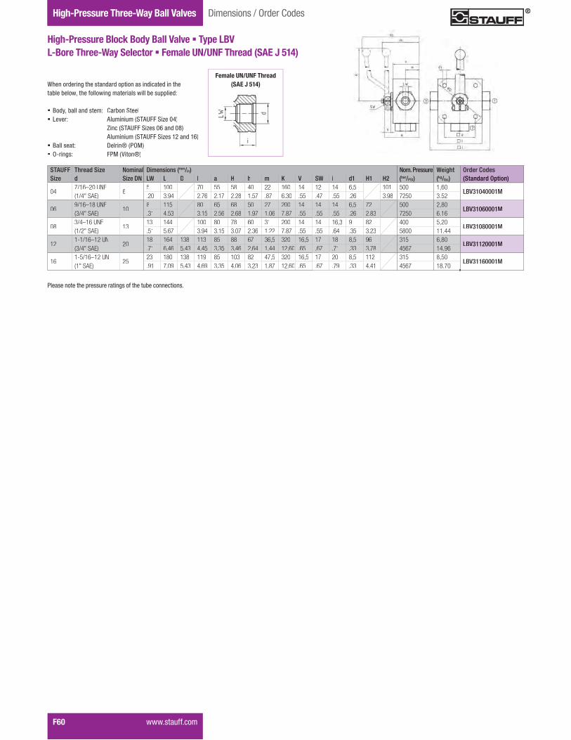
Gauge Isolator ValvesTwo-Way Ball ValvesHigh-Pressure Three-Way Ball Valves
F60 ���� ��&&����
Dimensions / Order Codes
High-Pressure Block Body Ball Valve � Type LBVL-Bore Three-Way Selector � Female UN/UNF Thread (SAE J 514)
STAUFF Thread Size Nominal Dimensions (mm/in) Nom. Pressure Weight Order CodesSize d Size DN LW L D l a H h m K V SW i d1 H1 H2 (bar/PSI) (kg/lbs) (Standard Option)
047/16–20 UNF(1/4" SAE)
65 100 70 55 58 40 22 160 14 12 14 6,5 101 500 1,60
LBV31040001M.20 3.94 2.76 2.17 2.28 1.57 .87 6.30 .55 .47 .55 .26 3.98 7250 3.52
069/16–18 UNF(3/4" SAE)
108 115 80 65 68 50 27 200 14 14 14 6,5 72 500 2,80
LBV31060001M.31 4.53 3.15 2.56 2.68 1.97 1.06 7.87 .55 .55 .55 .26 2.83 7250 6.16
083/4–16 UNF(1/2" SAE)
1313 144 100 80 78 60 31 200 14 14 16,3 9 82 400 5,20
LBV31080001M.51 5.67 3.94 3.15 3.07 2.36 1.22 7.87 .55 .55 .64 .35 3.23 5800 11.44
121-1/16–12 UN(3/4" SAE)
2018 164 138 113 85 88 67 36,5 320 16,5 17 18 8,5 96 315 6,80
LBV31120001M.71 6.46 5.43 4.45 3.35 3.46 2.64 1.44 12.60 .65 .67 .71 .33 3.78 4567 14.96
161-5/16–12 UN(1" SAE)
2523 180 138 119 85 103 82 47,5 320 16,5 17 20 8,5 112 315 8,50
LBV31160001M.91 7.09 5.43 4.69 3.35 4.06 3.23 1.87 12.60 .65 .67 .79 .33 4.41 4567 18.70
When ordering the standard option as indicated in the ���������{���&�������������� ������ ������!+
� Body, ball and stem: Carbon Steel� Lever: Aluminium (STAUFF Size 04)
Zinc (STAUFF Sizes 06 and 08)Aluminium (STAUFF Sizes 12 and 16)
� Ball seat: Delrin® (POM)� O-rings: FPM (Viton®)
Female UN/UNF Thread(SAE J 514)
"�� ����������� �������� �&����������������� �

Valv
esF
STAUFF Tube/Thread Size Nominal Dimensions (mm/in) Nom. Pressure Weight Order CodesSize d Size DN RA LW L D l a H h m K V SW i d1 H1 H2 (bar/PSI) (kg/lbs) (Standard Option)
02 06L / M12 x 1,5 46 5 105 70 55 58 40 22 160 14 12 10 6,5 101 500 1,60
LBV3DN0406L0001M.24 .20 4.13 2.76 2.17 2.28 1.57 .87 6.30 .55 .47 .39 .26 3.98 7250 3.52
04 08L / M14 x 1,5 68 5 105 70 55 58 40 22 160 14 12 10 6,5 101 500 1,80
LBV3DN0608L0001M.31 .20 4.13 2.76 2.17 2.28 1.57 .87 6.30 .55 .47 .39 .26 3.98 7250 3.96
05 10L / M16 x 1,5 810 8 114 80 65 68 50 27 200 14 14 11 6,5 72 500 2,60
LBV3DN0810L0001M.39 .31 4.49 3.15 2.56 2.68 1.97 1.06 7.87 .55 .55 .43 .26 2.83 7250 5.72
06 12L / M18 x 1,5 1012 8 114 80 65 68 50 27 200 14 14 11 6,5 72 500 2,60
LBV3DN1012L0001M.47 .31 4.49 3.15 2.56 2.68 1.97 1.06 7.87 .55 .55 .43 .26 2.83 7250 5.72
08 15L / M22 x 1,5 1315 13 137 100 80 78 60 31 200 14 14 12 9 82 400 4,70
LBV3DN1315L0001M.59 .51 5.39 3.94 3.15 3.07 2.36 1.22 7.87 .55 .55 .47 .35 3.23 5800 10.34
10 18L / M26 x 1,5 1618 18 137 113 85 88 67 36,5 320 16,5 17 12 8,5 82 400 4,70
LBV3DN1618L0001M.71 .71 5.39 4.45 3.35 3.46 2.64 1.44 12.60 .65 .67 .47 .33 3.23 5800 10.34
12 22L / M30 x 2 2022 23 152 138 119 85 103 82 47,5 320 16,5 17 14 8,5 96 315 6,60
LBV3DN2022L0001M.87 .91 5.98 5.43 4.69 3.35 4.06 3.23 1.87 12.60 .65 .67 .55 .33 3.78 4567 14.52
16 28L / M36 x 2 2528 23 166 138 119 85 103 82 47,5 320 16,5 17 14 8,5 112 315 8,00
LBV3DN2528L0001M1.10 .91 6.54 5.43 4.69 3.35 4.06 3.23 1.87 12.60 .65 .67 .55 .33 4.41 4567 17.60
20 35L / M45 x 2 25/3235 23 170 138 119 85 103 82 47,5 320 16,5 17 16 8,5 112 315 8,12
LBV3DN2535L0001M1.38 .91 6.69 5.43 4.69 3.35 4.06 3.23 1.87 12.60 .65 .67 .63 .33 4.41 4567 17.86
When ordering the standard option as indicated in the ���������{���&�������������� ������ ������!+
� Body, ball and stem: Carbon Steel� Lever: Aluminium (STAUFF Sizes 02 and 04)
Zinc (STAUFF Sizes 05 to 10 )Aluminium (STAUFF Sizes 12 to 20)
� Ball seat: Delrin® (POM)� O-rings: FPM (Viton®)
When ordering the standard option as indicated in the���������{���&�������������� ������ ������!+
� Body, ball and stem: Carbon Steel� Lever: Aluminium (STAUFF Sizes 02 and 04)
Zinc (STAUFF Sizes 05 to 10 )Aluminium (STAUFF Sizes 12 to 20)
� Ball seat: Delrin® (POM)� O-rings: FPM (Viton®)
���� ��&&���� F61
Dimensions / Order Codes High-Pressure Three-Way Ball Valves
High-Pressure Block Body Ball Valve � Type LBVL-Bore Three-Way Selector � 24° Cone Connection
Light Series (DIN 2353 / ISO 8434-1)
High-Pressure Block Body Ball Valve � Type LBVL-Bore Three-Way Selector � 24° Cone Connection
Heavy Series (DIN 2353 / ISO 8434-1)
STAUFF Tube/Thread Size Nominal Dimensions (mm/in) Nom. Pressure Weight Order CodesSize d Size DN RA LW L D l a H h m K V SW i d1 H1 H2 (bar/PSI) (kg/lbs) (Standard Option)
02 08S / M16 x 1,5 48 5 105 70 55 58 40 22 160 14 12 12 6,5 101 500 1,60
LBV3DN0408S0001M.31 .20 4.13 2.76 2.17 2.28 1.57 .87 6.30 .55 .47 .47 .26 3.98 7250 3.52
04 10S / M18 x 1,5 610 5 105 70 55 58 40 22 160 14 12 12 6,5 101 500 1,80
LBV3DN0610S0001M.39 .20 4.13 2.76 2.17 2.28 1.57 .87 6.30 .55 .47 .47 .26 3.98 7250 3.96
05 12S / M20 x 1,5 812 8 116 80 65 68 50 27 200 14 14 12 6,5 72 500 2,60
LBV3DN0812S0001M.47 .31 4.57 3.15 2.56 2.68 1.97 1.06 7.87 .55 .55 .47 .26 2.83 7250 5.72
06 14S / M22 x 1,5 1014 8 120 80 65 68 50 27 200 14 14 14 6,5 72 500 2,60
LBV3DN1014S0001M.55 .31 4.72 3.15 2.56 2.68 1.97 1.06 7.87 .55 .55 .55 .26 2.83 7250 5.72
08 16S / M24 x 1,5 1316 13 141 100 80 78 60 31 200 14 14 14 9 82 400 4,70
LBV3DN1316S0001M.63 .51 5.55 3.94 3.15 3.07 2.36 1.22 7.87 .55 .55 .55 .35 3.23 5800 10.34
10 20S / M30 x 2 1620 18 145 113 85 88 67 36,5 320 16,5 17 16 8,5 82 400 4,70
LBV3DN1620S0001M.79 .71 5.71 4.45 3.35 3.46 2.64 1.44 12.60 .65 .67 .63 .33 3.23 5800 10.34
12 25S / M36 x 2 2025 23 160 138 119 85 103 82 47,5 320 16,5 17 18 8,5 96 315 6,60
LBV3DN2025S0001M.98 .91 6.30 5.43 4.69 3.35 4.06 3.23 1.87 12.60 .65 .67 .71 .33 3.78 4567 14.52
16 30S / M42 x 2 2530 23 176 138 119 85 103 82 47,5 320 16,5 17 20 8,5 112 315 8,00
LBV3DN2530S0001M1.18 .91 6.93 5.43 4.69 3.35 4.06 3.23 1.87 12.60 .65 .67 .79 .33 4.41 4567 17.60
20 38S / M52 x 2 25/3238 23 180 138 119 85 103 82 47,5 320 16,5 17 22 8,5 112 315 8,12
LBV3DN2538S0001M1.50 .91 7.09 5.43 4.69 3.35 4.06 3.23 1.87 12.60 .65 .67 .87 .33 4.41 4567 17.86
24° Cone ConnectionCo e Co ect o(DIN 2353 / ISO 8434-1)DIN 2353 / ISO 8434-1
��>��� �!����������� ����������!�!��!������Q�
24° Cone Connection(DDIN 2353 / ISO 8434-1)
��>��� �!����������� ����������!�!��!������Q�
"�� ����������� �������� �&����������������� �
"�� ����������� �������� �&����������������� �
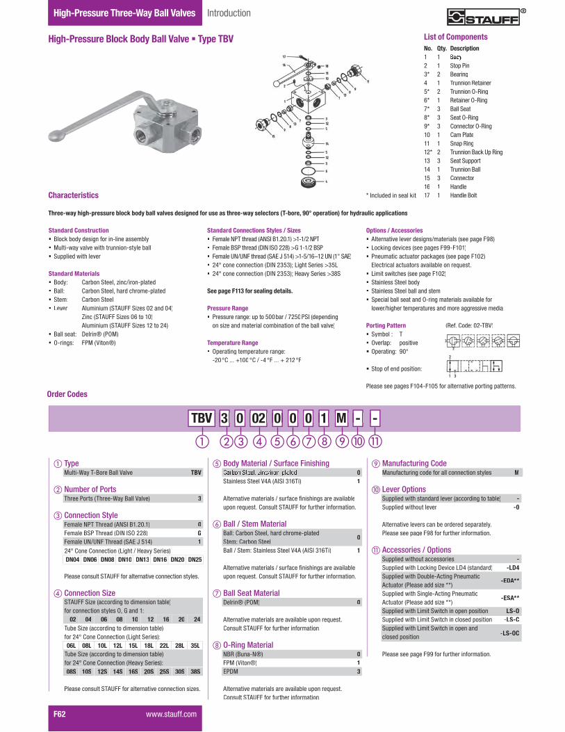
Gauge Isolator ValvesTwo-Way Ball ValvesHigh-Pressure Three-Way Ball Valves
F62 ���� ��&&����
High-Pressure Block Body Ball Valve � Type TBV
Introduction
No. Qty. Description1 12 1 Stop Pin3* 2 Bearing4 1 Trunnion Retainer5* 2 Trunnion O-Ring6* 1 Retainer O-Ring7* 3 Ball Seat8* 3 Seat O-Ring9* 3 Connector O-Ring10 1 Cam Plate11 1 Snap Ring12* 2 Trunnion Back Up Ring13 3 Seat Support14 1 Trunnion Ball15 3 Connector16 1 Handle17 1 Handle Bolt
List of Components
�'�&�*�!�+��$J.3�
Standard Connections Styles / Sizes� ������"J����!�K�?}.���������$����"J� �����.?"����!�\}�}?^��,����$���.?"� �����N��N������!�?K��%�#���$%������N����?K��� �#<���������������\}��4%4�������?���� �4%�� �#<���������������\}��4%4�����Q?���� �4,?
See page F113 for sealing details.
Pressure Range� Pressure range: up to 500bar / 7250PSI (depending
on size and material combination of the ball valve)
Temperature Range� Operating temperature range:
$�� <*���=��� <*�$# <� ��� = ��� <�
������������� �����������+���������������������������������������������������������� �������"������������ ���������
Standard Construction� Block body design for in-line assembly� _����$�Q����������������$ �Q������ ?������!���������
Standard Materials� Body: Carbon Steel, zinc/iron-plated� Ball: Carbon Steel, hard chrome-plated� Stem: Carbon Steel� Lever: Aluminium (STAUFF Sizes 02 and 04)
Zinc (STAUFF Sizes 06 to 10)Aluminium (STAUFF Sizes 12 to 24)
� Ball seat: Delrin® (POM)� O-rings: FPM (Viton®)
Characteristics * Included in seal kit
Options / Accessories� Alternative lever designs/materials (see page F98)� Locking devices (see pages F99-F101)� Pneumatic actuator packages (see page F102)
��������������� ������������� ��� ����� ������ � ����������� Stainless Steel body� Stainless Steel ball and stem� Special ball seat and O-ring materials available for
���������������������� �!�������� �����!�
Porting Pattern� Symbol : T� Overlap: positive� Operating: 90°
� Stop of end position:
"�� � ����� ���#$���%&������������������������ �Order Codes
� TypeMulti-Way T-Bore Ball Valve TBV
� Number of PortsThree Ports (Three-Way Ball Valve) 3
� Connection Style������"JJ���!�K�?}.������� 0Female BSP Thread (DIN ISO 228) GFemale UN/UNF Thread (SAE J 514) 1
"�� ���� ���?JKN��&��������������������� �Q�� �
� Connection Size
"�� ���� ���?JKN��&��������������������� �R� �
STAUFF Size (according to dimension table)for connection styles O, G and 1:
02 04 06 08 10 12 16 20 24
24° Cone Connection (Light / Heavy Series)DN04 DN06 DN08 DN10 DN13 DN16 DN20 DN25
Tube Size (according to dimension table)for 24° Cone Connection (Heavy Series):08S 10S 12S 14S 16S 20S 25S 30S 38S
Tube Size (according to dimension table)for 24° Cone Connection (Light Series):06L 08L 10L 12L 15L 18L 22L 28L 35L
M - - - M M 3 0 02 0 0 0 3 3 0 0 TBV 02 02 0 0 0 0 0 0 1 1 -
� Body Material / Surface Finishing0
Stainless Steel V4A (AISI 316Ti) 1
K��������������� � ��&��X�� ���� ����������������� ��*�� ���?JKN��&��&��������&��������
� Ball / Stem MaterialBall: Carbon Steel, hard chrome-platedStem: Carbon Steel
0
Ball / Stem: Stainless Steel V4A (AISI 316Ti) 1
K��������������� � ��&��X�� ���� ����������������� ��*�� ���?JKN��&��&��������&��������
� Ball Seat MaterialDelrin® (POM) 0
K��������������� ����������������� ��*�� ���?JKN��&��&��������&��������
O-Ring MaterialNBR (Buna-N®) 0FPM (Viton®) 1EPDM 3
K��������������� ����������������� ��*�� ���?JKN��&��&��������&��������
Manufacturing Code MManufacturing code for all connection styles M
� Lever Options?������!���� ��!�!����������!���������� -?������!������������ -0
K�������������� ������!���! ������Q�"�� � ������q,&��&��������&��������
� Accessories / Options?������!���������� ���� -?������!�������w���\������\#� ��!�!� -LD4?������!����\�����$K�����"�������Actuator (Please add size **)
-EDA**
?������!����?�����$K�����"�������Actuator (Please add size **)
-ESA**
?������!���������?������������� ����� $LS-O?������!���������?���������� �!�� ����� $LS-C?������!���������?������������!closed position -LS-OC
"�� � ������qq&��&��������&��������

Valv
esF
���� ��&&���� F63
Dimensions / Order Codes High-Pressure Three-Way Ball Valves
High-Pressure Block Body Ball Valve � Type TBVT-Bore Three-Way Selector � Female BSP Thread (DIN ISO 228)
STAUFF Thread Size Nominal Dimensions (mm/in) Nom. Pressure Weight Order CodesSize d Size DN LW L D l a H h m K V SW i d1 H1 H2 (bar/PSI) (kg/lbs) (Standard Option)
02 G 1/8 BSP 45 100 70 55 58 40 22 160 14 12 10 6,5 101 500 1,60
TBV3G020001M.20 3.94 2.76 2.17 2.28 1.57 .87 6.30 .55 .47 .39 .26 3.98 7250 3.52
04 G 1/4 BSP 65 100 70 55 58 40 22 160 14 12 14 6,5 101 500 1,60
TBV3G040001M.20 3.94 2.76 2.17 2.28 1.57 .87 6.30 .55 .47 .55 .26 3.98 7250 3.52
06 G 3/8 BSP 108 115 80 65 68 50 27 200 14 14 14 6,5 72 500 2,70
TBV3G060001M.31 4.53 3.15 2.56 2.68 1.97 1.06 7.87 .55 .55 .55 .26 2.83 7250 5.94
08 G 1/2 BSP 1313 136 100 80 78 60 31 200 14 14 16,3 9 82 400 4,90
TBV3G080001M.51 5.35 3.94 3.15 3.07 2.36 1.22 7.87 .55 .55 .64 .35 3.23 5800 10.78
10 G 5/8 BSP 1613 139 100 80 78 60 31 200 14 14 18 9 82 400 4,90
TBV3G100001M.51 5.47 3.94 3.15 3.07 2.36 1.22 7.87 .55 .55 .71 .35 3.23 5800 10.78
12 G 3/4 BSP 2018 154 138 113 85 88 67 36,5 320 16,5 17 18 8,5 96 315 6,70
TBV3G120001M.71 6.06 5.43 4.45 3.35 3.46 2.64 1.44 12.60 .65 .67 .71 .33 3.78 4567 14.74
16 G 1 BSP 2523 172 138 119 85 103 82 47,5 320 16,5 17 20 8,5 112 315 8,30
TBV3G160001M.91 6.77 5.43 4.69 3.35 4.06 3.23 1.87 12.60 .65 .67 .79 .33 4.41 4567 18.26
20 G 1-1/4 BSP 25/3223 180 138 119 85 103 82 47,5 320 16,5 17 22 8,5 112 315 8,50
TBV3G200001M.91 7.09 5.43 4.69 3.35 4.06 3.23 1.87 12.60 .65 .67 .87 .33 4.41 4567 18.70
24 G 1-1/2 BSP 25/4023 180 138 119 85 103 82 47,5 320 16,5 17 24 8,5 112 250 8,50
TBV3G240001M.91 7.09 5.43 4.69 3.35 4.06 3.23 1.87 12.60 .65 .67 .94 .33 4.41 3625 18.70
When ordering the standard option as indicated in the ���������{���&�������������� ������ ������!+
� Body, ball and stem: Carbon Steel� Lever: Aluminium (STAUFF Sizes 02 and 04)
Zinc (STAUFF Sizes 06 to 10)Aluminium (STAUFF Sizes 12 to 24)
� Ball seat: Delrin® (POM)� O-rings: FPM (Viton®)
Female BSP Thread e a e S ead(DIN ISO 228)
"�� ����������� �������� �&����������������� �
High-Pressure Block Body Ball Valve � Type TBVT-Bore Three-Way Selector � Female NPT Thread (ANSI B1.20.1)
STAUFF Thread Size Nominal Dimensions (mm/in) Nom. Pressure Weight Order CodesSize d Size DN LW L D l a H h m K V SW i d1 H1 H2 (bar/PSI) (kg/lbs) (Standard Option)
02 1/8 NPT 45 100 70 55 58 40 22 160 14 12 10,5 6,5 101 500 1,60
TBV30020001M.20 3.94 2.76 2.17 2.28 1.57 .87 6.30 .55 .47 .41 .26 3.98 7250 3.52
04 1/4 NPT 65 100 70 55 58 40 22 160 14 12 13,7 6,5 101 500 1,60
TBV30040001M.20 3.94 2.76 2.17 2.28 1.57 .87 6.30 .55 .47 .54 .26 3.98 7250 3.52
06 3/8 NPT 108 115 80 65 68 50 27 200 14 14 13,5 6,5 72 500 2,80
TBV30060001M.31 4.53 3.15 2.56 2.68 1.97 1.06 7.87 .55 .55 .53 .26 2.83 7250 6.16
08 1/2 NPT 1313 136 100 80 78 60 31 200 14 14 17 9 82 400 5,20
TBV30080001M.51 5.35 3.94 3.15 3.07 2.36 1.22 7.87 .55 .55 .67 .35 3.23 5800 11.44
12 3/4NPT 2018 154 138 113 85 88 67 36,5 320 16,5 17 18,3 8,5 96 315 6,80
TBV30120001M.71 6.06 5.43 4.45 3.35 3.46 2.64 1.44 12.60 .65 .67 .72 .33 3.78 4567 14.96
16 1 NPT 2523 172 138 119 85 103 82 47,5 320 16,5 17 21,6 8,5 112 315 8,50
TBV30160001M.91 6.77 5.43 4.69 3.35 4.06 3.23 1.87 12.60 .65 .67 .85 .33 4.41 4567 18.70
20 1-1/4 NPT 25/3223 180 138 119 85 103 82 47,5 320 16,5 17 22,1 8,5 112 315 8,80
TBV30200001M.91 7.09 5.43 4.69 3.35 4.06 3.23 1.87 12.60 .65 .67 .87 .33 4.41 4567 19.36
24 1-1/2 NPT 25/4023 180 138 119 85 103 82 47,5 320 16,5 17 22,1 8,5 112 250 8,80
TBV30240001M.91 7.09 5.43 4.69 3.35 4.06 3.23 1.87 12.60 .65 .67 .87 .33 4.41 3625 19.36
When ordering the standard option as indicated in the ���������{���&�������������� ������ ������!+
� Body, ball and stem: Carbon Steel� Lever: Aluminium (STAUFF Sizes 02 and 04)
Zinc (STAUFF Sizes 06 to 10)Aluminium (STAUFF Sizes 12 to 24)
� Ball seat: Delrin® (POM)� O-rings: FPM (Viton®)
Female NPT ThreadFemale NPT Threa(ANSI B1.20.1)
"�� ����������� �������� �&����������������� �
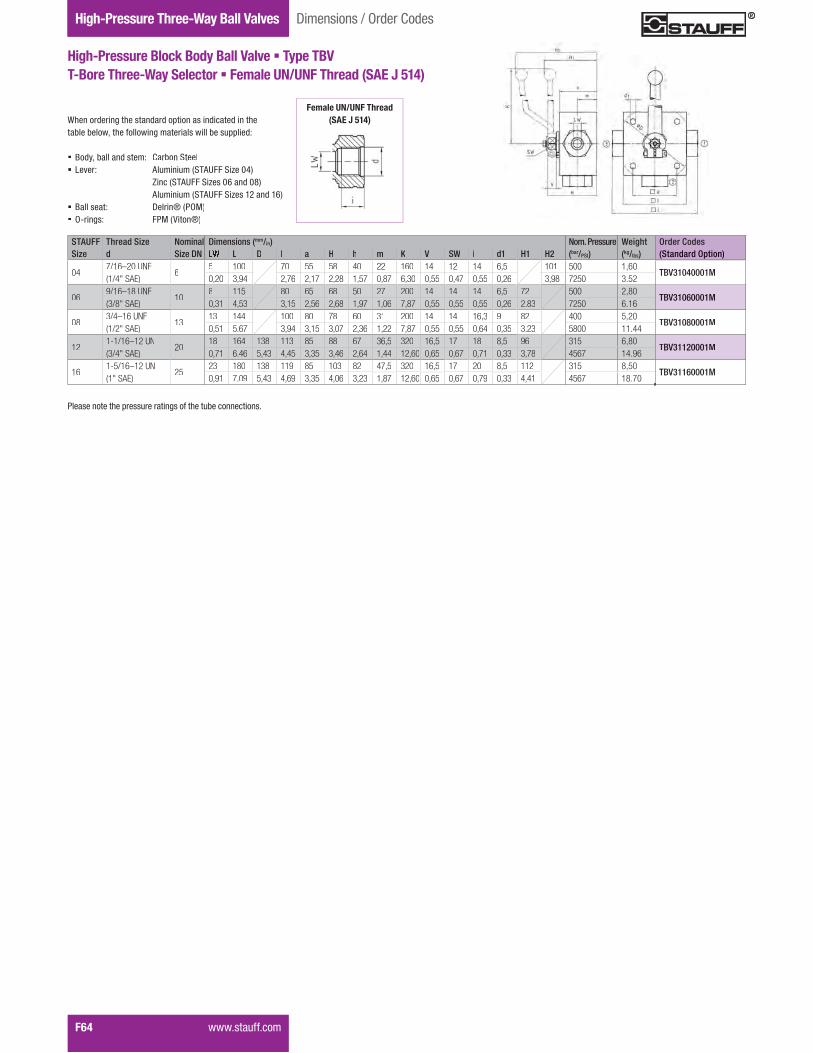
Gauge Isolator ValvesTwo-Way Ball ValvesHigh-Pressure Three-Way Ball Valves
F64 ���� ��&&����
Dimensions / Order Codes
High-Pressure Block Body Ball Valve � Type TBVT-Bore Three-Way Selector � Female UN/UNF Thread (SAE J 514)
STAUFF Thread Size Nominal Dimensions (mm/in) Nom. Pressure Weight Order CodesSize d Size DN L D l a H h m K V SW i d1 H1 H2 (bar/PSI) (kg/lbs) (Standard Option)
047/16–20 UNF(1/4" SAE)
65 100 70 55 58 40 22 160 14 12 14 6,5 101 500 1,60
TBV31040001M0,20 3,94 2,76 2,17 2,28 1,57 0,87 6,30 0,55 0,47 0,55 0,26 3,98 7250 3.52
069/16–18 UNF(3/8" SAE)
108 115 80 65 68 50 27 200 14 14 14 6,5 72 500 2,80
TBV31060001M0,31 4,53 3,15 2,56 2,68 1,97 1,06 7,87 0,55 0,55 0,55 0,26 2.83 7250 6.16
083/4–16 UNF(1/2" SAE)
1313 144 100 80 78 60 31 200 14 14 16,3 9 82 400 5,20
TBV31080001M0,51 5.67 3,94 3,15 3,07 2,36 1,22 7,87 0,55 0,55 0,64 0,35 3.23 5800 11.44
121-1/16–12 UN(3/4" SAE)
2018 164 138 113 85 88 67 36,5 320 16,5 17 18 8,5 96 315 6,80
TBV31120001M0,71 6.46 5,43 4,45 3,35 3,46 2,64 1,44 12,60 0,65 0,67 0,71 0,33 3,78 4567 14.96
161-5/16–12 UN(1" SAE)
2523 180 138 119 85 103 82 47,5 320 16,5 17 20 8,5 112 315 8,50
TBV31160001M0,91 7.09 5,43 4,69 3,35 4,06 3,23 1,87 12,60 0,65 0,67 0,79 0,33 4,41 4567 18.70
When ordering the standard option as indicated in the ���������{���&�������������� ������ ������!+
� Body, ball and stem: Carbon Steel� Lever: Aluminium (STAUFF Size 04)
Zinc (STAUFF Sizes 06 and 08)Aluminium (STAUFF Sizes 12 and 16)
� Ball seat: Delrin® (POM)� O-rings: FPM (Viton®)
Female UN/UNF Thread(SAE J 514)
"�� ����������� �������� �&����������������� �

Valv
esF
���� ��&&���� F65
Dimensions / Order Codes High-Pressure Three-Way Ball Valves
High-Pressure Block Body Ball Valve � Type TBVT-Bore Three-Way Selector � 24° Cone Connection
Light Series (DIN 2353 / ISO 8434-1)
High-Pressure Block Body Ball Valve � Type TBVT-Bore Three-Way Selector � 24° Cone Connection
Heavy Series (DIN 2353 / ISO 8434-1)
STAUFF Tube/Thread Size Nominal Dimensions (mm/in) Nom. Pressure Weight Order CodesSize d Size DN RA LW L D l a H h m K V SW i d1 H1 H2 (bar/PSI) (kg/lbs) (Standard Option)
02 06L / M12 x 1,5 46 5 105 70 55 58 40 22 160 14 12 10 6,5 101 500 1,60
TBV3DN0406L0001M.24 .20 4.13 2.76 2.17 2.28 1.57 .87 6.30 .55 .47 .39 .26 3.98 7250 3.52
04 08L / M14 x 1,5 68 5 105 70 55 58 40 22 160 14 12 10 6,5 101 500 1,80
TBV3DN0608L0001M.31 .20 4.13 2.76 2.17 2.28 1.57 .87 6.30 .55 .47 .39 .26 3.98 7250 3.96
05 10L / M16 x 1,5 810 8 114 80 65 68 50 27 200 14 14 11 6,5 72 500 2,60
TBV3DN0810L0001M.39 .31 4.49 3.15 2.56 2.68 1.97 1.06 7.87 .55 .55 .43 .26 2.83 7250 5.72
06 12L / M18 x 1,5 1012 8 114 80 65 68 50 27 200 14 14 11 6,5 72 500 2,60
TBV3DN1012L0001M.47 .31 4.49 3.15 2.56 2.68 1.97 1.06 7.87 .55 .55 .43 .26 2.83 7250 5.72
08 15L / M22 x 1,5 1315 13 137 100 80 78 60 31 200 14 14 12 9 82 400 4,70
TBV3DN1315L0001M.59 .51 5.39 3.94 3.15 3.07 2.36 1.22 7.87 .55 .55 .47 .35 3.23 5800 10.34
10 18L / M26 x 1,5 1618 18 137 113 85 88 67 36,5 320 16,5 17 12 8,5 82 400 4,70
TBV3DN1618L0001M.71 .71 5.39 4.45 3.35 3.46 2.64 1.44 12.60 .65 .67 .47 .33 3.23 5800 10.34
12 22L / M30 x 2 2022 23 152 138 119 85 103 82 47,5 320 16,5 17 14 8,5 96 315 6,60
TBV3DN2022L0001M.87 .91 5.98 5.43 4.69 3.35 4.06 3.23 1.87 12.60 .65 .67 .55 .33 3.78 4567 14.52
16 28L / M36 x 2 2528 23 166 138 119 85 103 82 47,5 320 16,5 17 14 8,5 112 315 8,00
TBV3DN2528L0001M1.10 .91 6.54 5.43 4.69 3.35 4.06 3.23 1.87 12.60 .65 .67 .55 .33 4.41 4567 17.60
20 35L / M45 x 2 25/3235 23 170 138 119 85 103 82 47,5 320 16,5 17 16 8,5 112 315 8,12
TBV3DN2535L0001M1.38 .91 6.69 5.43 4.69 3.35 4.06 3.23 1.87 12.60 .65 .67 .63 .33 4.41 4567 17.86
When ordering the standard option as indicated in the ���������{���&�������������� ������ ������!+
� Body, ball and stem: Carbon Steel� Lever: Aluminium (STAUFF Sizes 02 and 04)
Zinc (STAUFF Sizes 05 to 10 )Aluminium (STAUFF Sizes 12 to 20)
� Ball seat: Delrin® (POM)� O-rings: FPM (Viton®)
When ordering the standard option as indicated in the���������{���&�������������� ������ ������!+
� Body, ball and stem: Carbon Steel� Lever: Aluminium (STAUFF Sizes 02 and 04)
Zinc (STAUFF Sizes 05 to 10 )Aluminium (STAUFF Sizes 12 to 20)
� Ball seat: Delrin® (POM)� O-rings: FPM (Viton®)
STAUFF Tube/Thread Size Nominal Dimensions (mm/in) Nom. Pressure Weight Order CodesSize d Size DN RA LW L D l a H h m K V SW i d1 H1 H2 (bar/PSI) (kg/lbs) (Standard Option)
02 08S / M16 x 1,5 48 5 105 70 55 58 40 22 160 14 12 12 6,5 101 500 1,60
TBV3DN0408S0001M.31 .20 4.13 2.76 2.17 2.28 1.57 .87 6.30 .55 .47 .47 .26 3.98 7250 3.52
04 10S / M18 x 1,5 610 5 105 70 55 58 40 22 160 14 12 12 6,5 101 500 1,80
TBV3DN0610S0001M.39 .20 4.13 2.76 2.17 2.28 1.57 .87 6.30 .55 .47 .47 .26 3.98 7250 3.96
05 12S / M20 x 1,5 812 8 116 80 65 68 50 27 200 14 14 12 6,5 72 500 2,60
TBV3DN0812S0001M.47 .31 4.57 3.15 2.56 2.68 1.97 1.06 7.87 .55 .55 .47 .26 2.83 7250 5.72
06 14S / M22 x 1,5 1014 8 120 80 65 68 50 27 200 14 14 14 6,5 72 500 2,60
TBV3DN1014S0001M.55 .31 4.72 3.15 2.56 2.68 1.97 1.06 7.87 .55 .55 .55 .26 2.83 7250 5.72
08 16S / M24 x 1,5 1316 13 141 100 80 78 60 31 200 14 14 14 9 82 400 4,70
TBV3DN1316S0001M.63 .51 5.55 3.94 3.15 3.07 2.36 1.22 7.87 .55 .55 .55 .35 3.23 5800 10.34
10 20S / M30 x 2 1620 18 145 113 85 88 67 36,5 320 16,5 17 16 8,5 82 400 4,70
TBV3DN1620S0001M.79 .71 5.71 4.45 3.35 3.46 2.64 1.44 12.60 .65 .67 .63 .33 3.23 5800 10.34
12 25S / M36 x 2 2025 23 160 138 119 85 103 82 47,5 320 16,5 17 18 8,5 96 315 6,60
TBV3DN2025S0001M.98 .91 6.30 5.43 4.69 3.35 4.06 3.23 1.87 12.60 .65 .67 .71 .33 3.78 4567 14.52
16 30S / M42 x 2 2530 23 176 138 119 85 103 82 47,5 320 16,5 17 20 8,5 112 315 8,00
TBV3DN2530S0001M1.18 .91 6.93 5.43 4.69 3.35 4.06 3.23 1.87 12.60 .65 .67 .79 .33 4.41 4567 17.60
20 38S / M52 x 2 25/3238 23 180 138 119 85 103 82 47,5 320 16,5 17 22 8,5 112 315 8,12
TBV3DN2538S0001M1.50 .91 7.09 5.43 4.69 3.35 4.06 3.23 1.87 12.60 .65 .67 .87 .33 4.41 4567 17.86
24° Cone ConnectionCo e Co ect o(DIN 2353 / ISO 8434-1)DIN 2353 / ISO 8434-1
��>��� �!����������� ����������!�!��!������Q�
24° Cone Connection(DDIN 2353 / ISO 8434-1)
��>��� �!����������� ����������!�!��!������Q�
"�� ����������� �������� �&����������������� �
"�� ����������� �������� �&����������������� �
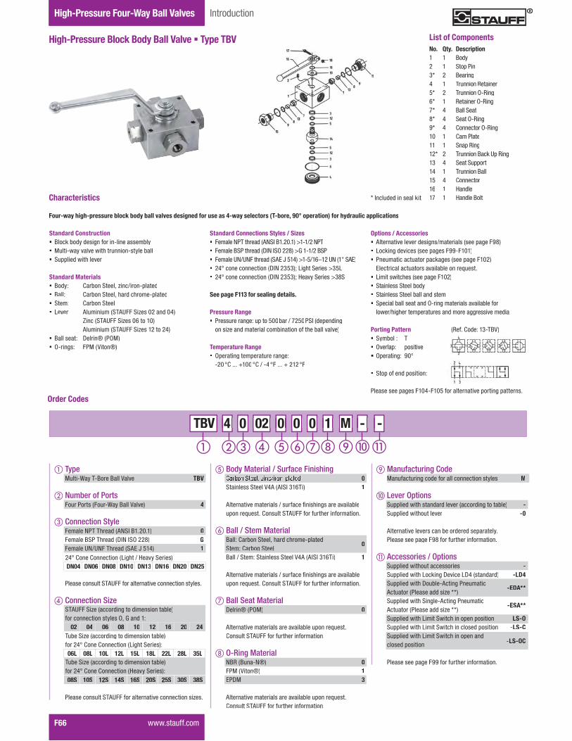
Gauge Isolator ValvesTwo-Way Ball ValvesHigh-Pressure Four-Way Ball Valves
F66� �����������
High-Pressure Block Body Ball Valve � Type TBV
Introduction
No. Qty. Description1 1 Body2 1 Stop Pin3* 2 Bearing4 1 Trunnion Retainer5* 2 Trunnion O-Ring6* 1 Retainer O-Ring7* 4 Ball Seat8* 4 Seat O-Ring9* 4 Connector O-Ring10 1 Cam Plate11 1 Snap Ring12* 2 Trunnion Back Up Ring13 4 Seat Support14 1 Trunnion Ball15 4 Connector16 1 Handle17 1 Handle Bolt
List of Components
Options / Accessories� Alternative lever designs/materials (see page F98)� Locking devices (see pages F99-F101)� Pneumatic actuator packages (see page F102)
��������������������������������������� ������������������������������ Stainless Steel body� Stainless Steel ball and stem� Special ball seat and O-ring materials available for
�����!����������������������"�������������������"��
Porting Pattern� Symbol : T� Overlap: positive� Operating: 90°
� Stop of end position:
#�������������������$%���&���������������������������������
�'���+�"�,��.%;<=�
Standard Connections Styles / Sizes� �������>#;������"��?>@D�<��������E�%�!��>#;� �������<@#������"��GD>�D@J���K��EM��%�!��<@#� �������N>!N>�������"��@? �Q�&�$��E�%&!�VW���N>���X�@? �� �$Y���������������GD>��.&.�Z�������@������E.&��� �$Y���������������GD>��.&.�Z�[���\�@������E.K@
See page F113 for sealing details.
Pressure Range� Pressure range: up to 500bar / 7250PSI (depending
on size and material combination of the ball valve)
Temperature Range� Operating temperature range:
%�� Y+�����]��� Y+�!�%$ Y� ��� ] ��� Y�
��������� �������������������������������� ����������������������������������!���������"�����������������������
Standard Construction� Block body design for in-line assembly� ^����%��\��������������������%��\�������� @������"�����������
Standard Materials� Body: Carbon Steel, zinc/iron-plated� Ball: Carbon Steel, hard chrome-plated� Stem: Carbon Steel� Lever: Aluminium (STAUFF Sizes 02 and 04)
Zinc (STAUFF Sizes 06 to 10)Aluminium (STAUFF Sizes 12 to 24)
� Ball seat: Delrin® (POM)� O-rings: FPM (Viton®)
Characteristics * Included in seal kit
Order Codes
� TypeMulti-Way T-Bore Ball Valve TBV
� Number of PortsFour Ports (Four-Way Ball Valve) 4
� Connection Style�������>#;�;����"��?>@D�<�������� 0Female BSP Thread (DIN ISO 228) GFemale UN/UNF Thread (SAE J 514) 1
#�������������@;?N�����������������������������\����
� Connection Size
#�������������@;?N�����������������������������~���
STAUFF Size (according to dimension table)for connection styles O, G and 1:
02 04 06 08 10 12 16 20 24
24° Cone Connection (Light / Heavy Series)DN04 DN06 DN08 DN10 DN13 DN16 DN20 DN25
Tube Size (according to dimension table)for 24° Cone Connection (Heavy Series):08S 10S 12S 14S 16S 20S 25S 30S 38S
Tube Size (according to dimension table)for 24° Cone Connection (Light Series):06L 08L 10L 12L 15L 18L 22L 28L 35L
M - - - M M 4 0 02 0 0 0 4 4 0 0 TBV 02 02 0 0 0 0 0 0 1 1 -
� Body Material / Surface Finishing0
Stainless Steel V4A (AISI 316Ti) 1
?���������������������!��������������������������������������������+�������@;?N������������������������
� Ball / Stem MaterialBall: Carbon Steel, hard chrome-platedStem: Carbon Steel
0
Ball / Stem: Stainless Steel V4A (AISI 316Ti) 1
?���������������������!��������������������������������������������+�������@;?N������������������������
� Ball Seat MaterialDelrin® (POM) 0
?�������������������������������������������������+�������@;?N������������������������
O-Ring MaterialNBR (Buna-N®) 0FPM (Viton®) 1EPDM 3
?�������������������������������������������������+�������@;?N������������������������
Manufacturing Code MManufacturing code for all connection styles M
� Lever Options@������"����������"��"�����������"������������� -@������"�������������� -0
?��������������������������"���"����������\�#�����������������K����������������������
� Accessories / Options@������"������������������ -@������"�������������G������G$������"��"� -LD4@������"������G�����%?�����#�������Actuator (Please add size **)
-EDA**
@������"������@�����%?�����#�������Actuator (Please add size **)
-ESA**
@������"������������@��������������������� %LS-O@������"������������@������������"��������� %LS-C@������"������������@���������������"closed position -LS-OC
#����������������������������������������

Valv
esF
����������� F67
Dimensions / Order Codes High-Pressure Four-Way Ball Valves
High-Pressure Block Body Ball Valve � Type TBVT-Bore Four-Way Selector � Female BSP Thread (DIN ISO 228)
STAUFF Thread Size Nominal Dimensions (mm/in) Nom. Pressure Weight Order CodesSize d Size DN LW L D l a H h m K V SW i d1 H1 H2 (bar/PSI) (kg/lbs) (Standard Option)
02 G 1/8 BSP 45 100 70 55 58 40 22 160 14 12 10 6,5 101 500 1,60
TBV4G020001M.20 3.94 2.76 2.17 2.28 1.57 .87 6.30 .55 .47 .39 .26 3.98 7250 3.52
04 G 1/4 BSP 65 100 70 55 58 40 22 160 14 12 14 6,5 101 500 1,60
TBV4G040001M.20 3.94 2.76 2.17 2.28 1.57 .87 6.30 .55 .47 .55 .26 3.98 7250 3.52
06 G 3/8 BSP 108 115 80 65 68 50 27 200 14 14 14 6,5 72 500 2,80
TBV4G060001M.31 4.53 3.15 2.56 2.68 1.97 1.06 7.87 .55 .55 .55 .26 2.83 7250 6.16
08 G 1/2 BSP 1313 136 100 80 78 60 31 200 14 14 16,3 9 82 400 4,90
TBV4G080001M.51 5.35 3.94 3.15 3.07 2.36 1.22 7.87 .55 .55 .64 .35 3.23 5800 10.78
10 G 5/8 BSP 1613 139 100 80 78 60 31 200 14 14 18 9 82 400 4,90
TBV4G100001M.51 5.47 3.94 3.15 3.07 2.36 1.22 7.87 .55 .55 .71 .35 3.23 5800 10.78
12 G 3/4 BSP 2018 154 138 113 85 88 67 36,5 320 16,5 17 18 8,5 96 315 6,80
TBV4G120001M.71 6.06 5.43 4.45 3.35 3.46 2.64 1.44 12.60 .65 .67 .71 .33 3.78 4567 14.96
16 G 1 BSP 2523 172 138 119 85 103 82 47,5 320 16,5 17 20 8,5 112 315 8,50
TBV4G160001M.91 6.77 5.43 4.69 3.35 4.06 3.23 1.87 12.60 .65 .67 .79 .33 4.41 4567 18.70
20 G 1-1/4 BSP 25/3223 180 138 119 85 103 82 47,5 320 16,5 17 22 8,5 112 315 8,80
TBV4G200001M.91 7.09 5.43 4.69 3.35 4.06 3.23 1.87 12.60 .65 .67 .87 .33 4.41 4567 19.36
24 G 1-1/2 BSP 25/4023 180 138 119 85 103 82 47,5 320 16,5 17 24 8,5 112 250 8,80
TBV4G240001M.91 7.09 5.43 4.69 3.35 4.06 3.23 1.87 12.60 .65 .67 .94 .33 4.41 3625 19.36
When ordering the standard option as indicated in the ���������������������������������������������������",
� Body, ball and stem: Carbon Steel� Lever: Aluminium (STAUFF Sizes 02 and 04)
Zinc (STAUFF Sizes 06 to 10)Aluminium (STAUFF Sizes 12 to 24)
� Ball seat: Delrin® (POM)� O-rings: FPM (Viton®)
Female BSP Thread e a e S ead(DIN ISO 228)
#�����������������������������������������������������
High-Pressure Block Body Ball Valve � Type TBVT-Bore Four-Way Selector � Female NPT Thread (ANSI B1.20.1)
STAUFF Thread Size Nominal Dimensions (mm/in) Nom. Pressure Weight Order CodesSize d Size DN LW L D l a H h m K V SW i d1 H1 H2 (bar/PSI) (kg/lbs) (Standard Option)
02 1/8 NPT 45 100 70 55 58 40 22 160 14 12 10,5 6,5 101 500 1,60
TBV40020001M.20 3.94 2.76 2.17 2.28 1.57 .87 6.30 .55 .47 .41 .26 3.98 7250 3.52
04 1/4 NPT 65 100 70 55 58 40 22 160 14 12 13,7 6,5 101 500 1,60
TBV40040001M.20 3.94 2.76 2.17 2.28 1.57 .87 6.30 .55 .47 .54 .26 3.98 7250 3.52
06 3/8 NPT 108 115 80 65 68 50 27 200 14 14 13,5 6,5 72 500 2,80
TBV40060001M.31 4.53 3.15 2.56 2.68 1.97 1.06 7.87 .55 .55 .53 .26 2.83 7250 6.16
08 1/2 NPT 1313 136 100 80 78 60 31 200 14 14 17 9 82 400 4,90
TBV40080001M.51 5.35 3.94 3.15 3.07 2.36 1.22 7.87 .55 .55 .67 .35 3.23 5800 10.78
12 3/4NPT 2018 154 138 113 85 88 67 36,5 320 16,5 17 18,3 8,5 96 315 6,80
TBV40120001M.71 6.06 5.43 4.45 3.35 3.46 2.64 1.44 12.60 .65 .67 .72 .33 3.78 4567 14.96
16 1 NPT 2523 172 138 119 85 103 82 47,5 320 16,5 17 21,6 8,5 112 315 8,50
TBV40160001M.91 6.77 5.43 4.69 3.35 4.06 3.23 1.87 12.60 .65 .67 .85 .33 4.41 4567 18.70
20 1-1/4 NPT 25/3223 180 138 119 85 103 82 47,5 320 16,5 17 22,1 8,5 112 315 8,80
TBV40200001M.91 7.09 5.43 4.69 3.35 4.06 3.23 1.87 12.60 .65 .67 .87 .33 4.41 4567 19.36
24 1-1/2 NPT 25/4023 180 138 119 85 103 82 47,5 320 16,5 17 22,1 8,5 112 250 8,80
TBV40240001M.91 7.09 5.43 4.69 3.35 4.06 3.23 1.87 12.60 .65 .67 .87 .33 4.41 3625 19.36
When ordering the standard option as indicated in the ���������������������������������������������������",
� Body, ball and stem: Carbon Steel� Lever: Aluminium (STAUFF Sizes 02 and 04)
Zinc (STAUFF Sizes 06 to 10)Aluminium (STAUFF Sizes 12 to 24)
� Ball seat: Delrin® (POM)� O-rings: FPM (Viton®)
Female NPT Threade a e ea(ANSI B1.20.1)
#�����������������������������������������������������
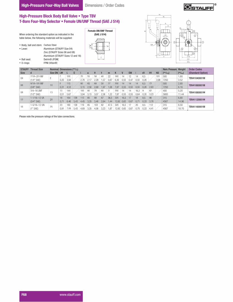
High-Pressure Block Body Ball Valve � Type TBVT-Bore Four-Way Selector � Female UN/UNF Thread (SAE J 514)
Gauge Isolator ValvesTwo-Way Ball ValvesHigh-Pressure Four-Way Ball Valves
F68� �����������
Dimensions / Order Codes
STAUFF Thread Size Nominal Dimensions (mm/in) Nom. Pressure Weight Order CodesSize d Size DN L D l a H h m K V SW i d1 H1 H2 (bar/PSI) (kg/lbs) (Standard Option)
047/16–20 UNF(1/4" SAE)
65 100 70 55 58 40 22 160 14 12 14 6,5 101 500 1,60
TBV41040001M0,20 3,94 2,76 2,17 2,28 1,57 0,87 6,30 0,55 0,47 0,55 0,26 3,98 7250 3.52
069/16–18 UNF(3/8" SAE)
108 115 80 65 68 50 27 200 14 14 14 6,5 72 500 2,80
TBV41060001M0,31 4,53 3,15 2,56 2,68 1,97 1,06 7,87 0,55 0,55 0,55 0,26 2.83 7250 6.16
083/4–16 UNF(1/2" SAE)
1313 144 100 80 78 60 31 200 14 14 16,3 9 82 400 5,20
TBV41080001M0,51 5.67 3,94 3,15 3,07 2,36 1,22 7,87 0,55 0,55 0,64 0,35 3.23 5800 11.44
121-1/16–12 UN(3/4" SAE)
2018 164 138 113 85 88 67 36,5 320 16,5 17 18 8,5 96 315 6,80
TBV41120001M0,71 6.46 5,43 4,45 3,35 3,46 2,64 1,44 12,60 0,65 0,67 0,71 0,33 3,78 4567 14.96
161-5/16–12 UN(1" SAE)
2523 180 138 119 85 103 82 47,5 320 16,5 17 20 8,5 112 315 8,50
TBV41160001M0,91 7.09 5,43 4,69 3,35 4,06 3,23 1,87 12,60 0,65 0,67 0,79 0,33 4,41 4567 18.70
When ordering the standard option as indicated in the ���������������������������������������������������",
� Body, ball and stem: Carbon Steel� Lever: Aluminium (STAUFF Size 04)
Zinc (STAUFF Sizes 06 and 08)Aluminium (STAUFF Sizes 12 and 16)
� Ball seat: Delrin® (POM)� O-rings: FPM (Viton®)
Female UN/UNF Thread(SAE J 514)
#�����������������������������������������������������

Valv
esF
High-Pressure Block Body Ball Valve � Type TBVT-Bore Four-Way Selector � 24° Cone Connection
Light Series (DIN 2353 / ISO 8434-1)
High-Pressure Block Body Ball Valve � Type TBVT-Bore Four-Way Selector � 24° Cone Connection
Heavy Series (DIN 2353 / ISO 8434-1)
����������� F69
Dimensions / Order Codes High-Pressure Four-Way Ball Valves
STAUFF Tube/Thread Size Nominal Dimensions (mm/in) Nom. Pressure Weight Order CodesSize d Size DN RA LW L D l a H h m K V SW i d1 H1 H2 (bar/PSI) (kg/lbs) (Standard Option)
02 06L / M12 x 1,5 46 5 105 70 55 58 40 22 160 14 12 10 6,5 101 500 1,60
TBV4DN0406L0001M.24 .20 4.13 2.76 2.17 2.28 1.57 .87 6.30 .55 .47 .39 .26 3.98 7250 3.52
04 08L / M14 x 1,5 68 5 105 70 55 58 40 22 160 14 12 10 6,5 101 500 1,80
TBV4DN0608L0001M.31 .20 4.13 2.76 2.17 2.28 1.57 .87 6.30 .55 .47 .39 .26 3.98 7250 3.96
05 10L / M16 x 1,5 810 8 114 80 65 68 50 27 200 14 14 11 6,5 72 500 2,60
TBV4DN0810L0001M.39 .31 4.49 3.15 2.56 2.68 1.97 1.06 7.87 .55 .55 .43 .26 2.83 7250 5.72
06 12L / M18 x 1,5 1012 8 114 80 65 68 50 27 200 14 14 11 6,5 72 500 2,60
TBV4DN1012L0001M.47 .31 4.49 3.15 2.56 2.68 1.97 1.06 7.87 .55 .55 .43 .26 2.83 7250 5.72
08 15L / M22 x 1,5 1315 13 137 100 80 78 60 31 200 14 14 12 9 82 400 4,70
TBV4DN1315L0001M.59 .51 5.39 3.94 3.15 3.07 2.36 1.22 7.87 .55 .55 .47 .35 3.23 5800 10.34
10 18L / M26 x 1,5 1618 18 137 113 85 88 67 36,5 320 16,5 17 12 8,5 82 400 4,70
TBV4DN1618L0001M.71 .71 5.39 4.45 3.35 3.46 2.64 1.44 12.60 .65 .67 .47 .33 3.23 5800 10.34
12 22L / M30 x 2 2022 23 152 138 119 85 103 82 47,5 320 16,5 17 14 8,5 96 315 6,60
TBV4DN2022L0001M.87 .91 5.98 5.43 4.69 3.35 4.06 3.23 1.87 12.60 .65 .67 .55 .33 3.78 4567 14.52
16 28L / M36 x 2 2528 23 166 138 119 85 103 82 47,5 320 16,5 17 14 8,5 112 315 8,00
TBV4DN2528L0001M1.10 .91 6.54 5.43 4.69 3.35 4.06 3.23 1.87 12.60 .65 .67 .55 .33 4.41 4567 17.60
20 35L / M45 x 2 25/3235 23 170 138 119 85 103 82 47,5 320 16,5 17 16 8,5 112 315 8,12
TBV4DN2535L0001M1.38 .91 6.69 5.43 4.69 3.35 4.06 3.23 1.87 12.60 .65 .67 .63 .33 4.41 4567 17.86
When ordering the standard option as indicated in the ���������������������������������������������������",
� Body, ball and stem: Carbon Steel� Lever: Aluminium (STAUFF Sizes 02 and 04)
Zinc (STAUFF Sizes 05 to 10 )Aluminium (STAUFF Sizes 12 to 20)
� Ball seat: Delrin® (POM)� O-rings: FPM (Viton®)
When ordering the standard option as indicated in the ���������������������������������������������������",
� Body, ball and stem: Carbon Steel� Lever: Aluminium (STAUFF Sizes 02 and 04)
Zinc (STAUFF Sizes 05 to 10 )Aluminium (STAUFF Sizes 12 to 20)
� Ball seat: Delrin® (POM)� O-rings: FPM (Viton®)
STAUFF Tube/Thread Size Nominal Dimensions (mm/in) Nom. Pressure Weight Order CodesSize d Size DN RA LW L D l a H h m K V SW i d1 H1 H2 (bar/PSI) (kg/lbs) (Standard Option)
02 08S / M16 x 1,5 48 5 105 70 55 58 40 22 160 14 12 12 6,5 101 500 1,60
TBV4DN0408S0001M.31 .20 4.13 2.76 2.17 2.28 1.57 .87 6.30 .55 .47 .47 .26 3.98 7250 3.52
04 10S / M18 x 1,5 610 5 105 70 55 58 40 22 160 14 12 12 6,5 101 500 1,80
TBV4DN0610S0001M.39 .20 4.13 2.76 2.17 2.28 1.57 .87 6.30 .55 .47 .47 .26 3.98 7250 3.96
05 12S / M20 x 1,5 812 8 116 80 65 68 50 27 200 14 14 12 6,5 72 500 2,60
TBV4DN0812S0001M.47 .31 4.57 3.15 2.56 2.68 1.97 1.06 7.87 .55 .55 .47 .26 2.83 7250 5.72
06 14S / M22 x 1,5 1014 8 120 80 65 68 50 27 200 14 14 14 6,5 72 500 2,60
TBV4DN1014S0001M.55 .31 4.72 3.15 2.56 2.68 1.97 1.06 7.87 .55 .55 .55 .26 2.83 7250 5.72
08 16S / M24 x 1,5 1316 13 141 100 80 78 60 31 200 14 14 14 9 82 400 4,70
TBV4DN1316S0001M.63 .51 5.55 3.94 3.15 3.07 2.36 1.22 7.87 .55 .55 .55 .35 3.23 5800 10.34
10 20S / M30 x 2 1620 18 145 113 85 88 67 36,5 320 16,5 17 16 8,5 82 400 4,70
TBV4DN1620S0001M.79 .71 5.71 4.45 3.35 3.46 2.64 1.44 12.60 .65 .67 .63 .33 3.23 5800 10.34
12 25S / M36 x 2 2025 23 160 138 119 85 103 82 47,5 320 16,5 17 18 8,5 96 315 6,60
TBV4DN2025S0001M.98 .91 6.30 5.43 4.69 3.35 4.06 3.23 1.87 12.60 .65 .67 .71 .33 3.78 4567 14.52
16 30S / M42 x 2 2530 23 176 138 119 85 103 82 47,5 320 16,5 17 20 8,5 112 315 8,00
TBV4DN2530S0001M1.18 .91 6.93 5.43 4.69 3.35 4.06 3.23 1.87 12.60 .65 .67 .79 .33 4.41 4567 17.60
20 38S / M52 x 2 25/3238 23 180 138 119 85 103 82 47,5 320 16,5 17 22 8,5 112 315 8,12
TBV4DN2538S0001M1.50 .91 7.09 5.43 4.69 3.35 4.06 3.23 1.87 12.60 .65 .67 .87 .33 4.41 4567 17.86
24° Cone ConnectionCo e Co ect o(DIN 2353 / ISO 8434-1)DIN 2353 / ISO 8434-1
[����������"��������������������������"�"����"������\�
24° Cone Connection(DDIN 2353 / ISO 8434-1)
[����������"��������������������������"�"����"������\�
#�����������������������������������������������������
#�����������������������������������������������������
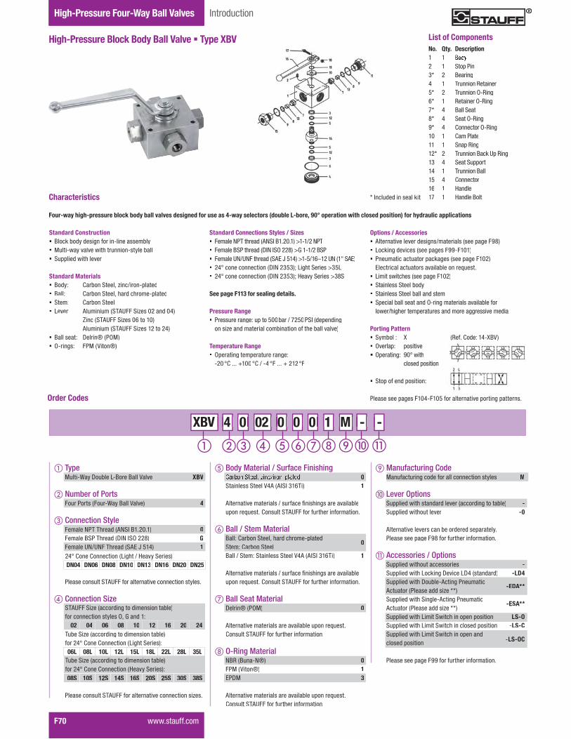
Gauge Isolator ValvesTwo-Way Ball ValvesHigh-Pressure Four-Way Ball Valves
F70� �����������
High-Pressure Block Body Ball Valve � Type XBV
Introduction
No. Qty. Description1 12 1 Stop Pin3* 2 Bearing4 1 Trunnion Retainer5* 2 Trunnion O-Ring6* 1 Retainer O-Ring7* 4 Ball Seat8* 4 Seat O-Ring9* 4 Connector O-Ring10 1 Cam Plate11 1 Snap Ring12* 2 Trunnion Back Up Ring13 4 Seat Support14 1 Trunnion Ball15 4 Connector16 1 Handle17 1 Handle Bolt
List of Components
Options / Accessories� Alternative lever designs/materials (see page F98)� Locking devices (see pages F99-F101)� Pneumatic actuator packages (see page F102)
��������������������������������������� ������������������������������ Stainless Steel body� Stainless Steel ball and stem� Special ball seat and O-ring materials available for
�����!����������������������"�������������������"��
Porting Pattern� Symbol : X� Overlap: positive� J��������, ��Y�����
closed position
� Stop of end position:
#�������������������$%���&���������������������������������
�'���+�"�,��$%�<=�
Standard Connections Styles / Sizes� �������>#;������"��?>@D�<��������E�%�!��>#;� �������<@#������"��GD>�D@J���K��EM��%�!��<@#� �������N>!N>�������"��@? �Q�&�$��E�%&!�VW���N>���X�@? �� �$Y���������������GD>��.&.�Z�������@������E.&��� �$Y���������������GD>��.&.�Z�[���\�@������E.K@
See page F113 for sealing details.
Pressure Range� Pressure range: up to 500bar / 7250PSI (depending
on size and material combination of the ball valve)
Temperature Range� Operating temperature range:
%�� Y+�����]��� Y+�!�%$ Y� ��� ] ��� Y�
��������� �������������������������������� �������������������������������#��������!���������������������������"�����������������������
Standard Construction� Block body design for in-line assembly� ^����%��\��������������������%��\�������� @������"�����������
Standard Materials� Body: Carbon Steel, zinc/iron-plated� Ball: Carbon Steel, hard chrome-plated� Stem: Carbon Steel� Lever: Aluminium (STAUFF Sizes 02 and 04)
Zinc (STAUFF Sizes 06 to 10)Aluminium (STAUFF Sizes 12 to 24)
� Ball seat: Delrin® (POM)� O-rings: FPM (Viton®)
Characteristics * Included in seal kit
Order Codes
� TypeMulti-Way Double L-Bore Ball Valve XBV
� Number of PortsFour Ports (Four-Way Ball Valve) 4
� Connection Style�������>#;�;����"��?>@D�<�������� 0Female BSP Thread (DIN ISO 228) GFemale UN/UNF Thread (SAE J 514) 1
#�������������@;?N�����������������������������\����
� Connection Size
#�������������@;?N�����������������������������~���
STAUFF Size (according to dimension table)for connection styles O, G and 1:
02 04 06 08 10 12 16 20 24
24° Cone Connection (Light / Heavy Series)DN04 DN06 DN08 DN10 DN13 DN16 DN20 DN25
Tube Size (according to dimension table)for 24° Cone Connection (Heavy Series):08S 10S 12S 14S 16S 20S 25S 30S 38S
Tube Size (according to dimension table)for 24° Cone Connection (Light Series):06L 08L 10L 12L 15L 18L 22L 28L 35L
M - - - M M 4 0 02 0 0 0 4 4 0 0 XBV 02 02 0 0 0 0 0 0 1 1 -
� Body Material / Surface Finishing0
Stainless Steel V4A (AISI 316Ti) 1
?���������������������!��������������������������������������������+�������@;?N������������������������
� Ball / Stem MaterialBall: Carbon Steel, hard chrome-platedStem: Carbon Steel
0
Ball / Stem: Stainless Steel V4A (AISI 316Ti) 1
?���������������������!��������������������������������������������+�������@;?N������������������������
� Ball Seat MaterialDelrin® (POM) 0
?�������������������������������������������������+�������@;?N������������������������
O-Ring MaterialNBR (Buna-N®) 0FPM (Viton®) 1EPDM 3
?�������������������������������������������������+�������@;?N������������������������
Manufacturing Code MManufacturing code for all connection styles M
� Lever Options@������"����������"��"�����������"������������� -@������"�������������� -0
?��������������������������"���"����������\�#�����������������K����������������������
� Accessories / Options@������"������������������ -@������"�������������G������G$������"��"� -LD4@������"������G�����%?�����#�������Actuator (Please add size **)
-EDA**
@������"������@�����%?�����#�������Actuator (Please add size **)
-ESA**
@������"������������@��������������������� %LS-O@������"������������@������������"��������� %LS-C@������"������������@���������������"closed position -LS-OC
#����������������������������������������

Valv
esF
����������� F71
Dimensions / Order Codes High-Pressure Four-Way Ball Valves
High-Pressure Block Body Ball Valve � Type XBVDouble L-Bore Four-Way Selector � Female NPT Thread (ANSI B1.20.1)
STAUFF Thread Size Nominal Dimensions (mm/in) Nom. Pressure Weight Order CodesSize d Size DN LW L D l a H h m K V SW i d1 H1 H2 (bar/PSI) (kg/lbs) (Standard Option)
02 1/8 NPT 44 100 70 55 58 40 22 160 14 12 10,5 6,5 101 500 1,60
XBV40020001M.16 3.94 2.76 2.17 2.28 1.57 .87 6.30 .55 .47 .41 .26 3.98 7250 3.52
04 1/4 NPT 64 100 70 55 58 40 22 160 14 12 13,7 6,5 101 500 1,60
XBV40040001M.16 3.94 2.76 2.17 2.28 1.57 .87 6.30 .55 .47 .54 .26 3.98 7250 3.52
06 3/8 NPT 107 115 80 65 68 50 27 200 14 14 13,5 6,5 72 500 2,80
XBV40060001M.28 4.53 3.15 2.56 2.68 1.97 1.06 7.87 .55 .55 .53 .26 2.83 7250 6.16
08 1/2 NPT 1310 136 100 80 78 60 31 200 14 14 17 9 82 400 4,90
XBV40080001M.39 5.35 3.94 3.15 3.07 2.36 1.22 7.87 .55 .55 .67 .35 3.23 5800 10.78
12 3/4NPT 2014 154 138 113 85 88 67 36,5 320 16,5 17 18,3 8,5 96 315 6,80
XBV40120001M.55 6.06 5.43 4.45 3.35 3.46 2.64 1.44 12.60 .65 .67 .72 .33 3.78 4567 14.96
16 1 NPT 2517 172 138 119 85 103 82 47,5 320 16,5 17 21,6 8,5 112 315 8,50
XBV40160001M.67 6.77 5.43 4.69 3.35 4.06 3.23 1.87 12.60 .65 .67 .85 .33 4.41 4567 18.70
20 1-1/4 NPT 25/3217 180 138 119 85 103 82 47,5 320 16,5 17 22,1 8,5 112 315 8,80
XBV40200001M.67 7.09 5.43 4.69 3.35 4.06 3.23 1.87 12.60 .65 .67 .87 .33 4.41 4567 19.36
24 1-1/2 NPT 25/4017 180 138 119 85 103 82 47,5 320 16,5 17 22,1 8,5 112 250 8,80
XBV40240001M.67 7.09 5.43 4.69 3.35 4.06 3.23 1.87 12.60 .65 .67 .87 .33 4.41 3625 19.36
When ordering the standard option as indicated in the ���������������������������������������������������",
� Body, ball and stem: Carbon Steel� Lever: Aluminium (STAUFF Sizes 02 and 04)
Zinc (STAUFF Sizes 06 to 10)Aluminium (STAUFF Sizes 12 to 24)
� Ball seat: Delrin® (POM)� O-rings: FPM (Viton®)
Female NPT Thread(ANSI B1.20.1)
#�����������������������������������������������������
High-Pressure Block Body Ball Valve � Type XBVDouble L-Bore Four-Way Selector � Female BSP Thread (DIN ISO 228)
STAUFF Thread Size Nominal Dimensions (mm/in) Nom. Pressure Weight Order CodesSize d Size DN LW L D l a H h m K V SW i d1 H1 H2 (bar/PSI) (kg/lbs) (Standard Option)
02 G 1/8 BSP 44 100 70 55 58 40 22 160 14 12 10 6,5 101 500 1,60
XBV4G020001M.16 3.94 2.76 2.17 2.28 1.57 .87 6.30 .55 .47 .39 .26 3.98 7250 3.52
04 G 1/4 BSP 64 100 70 55 58 40 22 160 14 12 14 6,5 101 500 1,60
XBV4G040001M.16 3.94 2.76 2.17 2.28 1.57 .87 6.30 .55 .47 .55 .26 3.98 7250 3.52
06 G 3/8 BSP 107 115 80 65 68 50 27 200 14 14 14 6,5 72 500 2,80
XBV4G060001M.28 4.53 3.15 2.56 2.68 1.97 1.06 7.87 .55 .55 .55 .26 2.83 7250 6.16
08 G 1/2 BSP 1310 136 100 80 78 60 31 200 14 14 16,3 9 82 400 4,90
XBV4G080001M.39 5.35 3.94 3.15 3.07 2.36 1.22 7.87 .55 .55 .64 .35 3.23 5800 10.78
10 G 5/8 BSP 1610 139 100 80 78 60 31 200 14 14 18 9 82 400 4,90
XBV4G100001M.39 5.47 3.94 3.15 3.07 2.36 1.22 7.87 .55 .55 .71 .35 3.23 5800 10.78
12 G 3/4 BSP 2014 154 138 113 85 88 67 36,5 320 16,5 17 18 8,5 96 315 6,80
XBV4G120001M.55 6.06 5.43 4.45 3.35 3.46 2.64 1.44 12.60 .65 .67 .71 .33 3.78 4567 14.96
16 G 1 BSP 2517 172 138 119 85 103 82 47,5 320 16,5 17 20 8,5 112 315 8,50
XBV4G160001M.67 6.77 5.43 4.69 3.35 4.06 3.23 1.87 12.60 .65 .67 .79 .33 4.41 4567 18.70
20 G 1-1/4 BSP 25/3217 180 138 119 85 103 82 47,5 320 16,5 17 22 8,5 112 315 8,80
XBV4G200001M.67 7.09 5.43 4.69 3.35 4.06 3.23 1.87 12.60 .65 .67 .87 .33 4.41 4567 19.36
24 G 1-1/2 BSP 25/4017 180 138 119 85 103 82 47,5 320 16,5 17 24 8,5 112 250 8,80
XBV4G240001M.67 7.09 5.43 4.69 3.35 4.06 3.23 1.87 12.60 .65 .67 .94 .33 4.41 3625 19.36
When ordering the standard option as indicated in the ���������������������������������������������������",
� Body, ball and stem: Carbon Steel� Lever: Aluminium (STAUFF Sizes 02 and 04)
Zinc (STAUFF Sizes 06 to 10)Aluminium (STAUFF Sizes 12 to 24)
� Ball seat: Delrin® (POM)� O-rings: FPM (Viton®)
#�����������������������������������������������������

High-Pressure Block Body Ball Valve � Type XBVDouble L-Bore Four-Way Selector � Female UN/UNF Thread (SAE J 514)
Gauge Isolator ValvesTwo-Way Ball ValvesHigh-Pressure Four-Way Ball Valves
F72� �����������
Dimensions / Order Codes
STAUFF Thread Size Nominal Dimensions (mm/in) Nom. Pressure Weight Order CodesSize d Size DN L D l a H h m K V SW i d1 H1 H2 (bar/PSI) (kg/lbs) (Standard Option)
047/16–20 UNF(1/4" SAE)
64 100 70 55 58 40 22 160 14 12 14 6,5 101 500 1,60
XBV41040001M.16 3,94 2,76 2,17 2,28 1,57 0,87 6,30 0,55 0,47 0,55 0,26 3,98 7250 3.52
069/16–18 UNF(3/8" SAE)
107 115 80 65 68 50 27 200 14 14 14 6,5 72 500 2,80
XBV41060001M.28 4,53 3,15 2,56 2,68 1,97 1,06 7,87 0,55 0,55 0,55 0,26 2.83 7250 6.16
083/4–16 UNF(1/2" SAE)
1310 144 100 80 78 60 31 200 14 14 16,3 9 82 400 5,20
XBV41080001M.39 5.67 3,94 3,15 3,07 2,36 1,22 7,87 0,55 0,55 0,64 0,35 3.23 5800 11.44
121-1/16–12 UN(3/4" SAE)
2014 164 138 113 85 88 67 36,5 320 16,5 17 18 8,5 96 315 6,80
XBV41120001M.55 6.46 5,43 4,45 3,35 3,46 2,64 1,44 12,60 0,65 0,67 0,71 0,33 3,78 4567 14.96
161-5/16–12 UN(1" SAE)
2517 180 138 119 85 103 82 47,5 320 16,5 17 20 8,5 112 315 8,50
XBV41160001M.67 7.09 5,43 4,69 3,35 4,06 3,23 1,87 12,60 0,65 0,67 0,79 0,33 4,41 4567 18.70
When ordering the standard option as indicated in the ���������������������������������������������������",
� Body, ball and stem: Carbon Steel� Lever: Aluminium (STAUFF Size 04)
Zinc (STAUFF Sizes 06 and 08)Aluminium (STAUFF Sizes 12 and 16)
� Ball seat: Delrin® (POM)� O-rings: FPM (Viton®)
Female UN/UNF Thread(SAE J 514)
#�����������������������������������������������������

Valv
esF
High-Pressure Block Body Ball Valve � Type XBVDouble L-Bore Four-Way Selector � 24° Cone Connection
Light Series (DIN 2353 / ISO 8434-1)
High-Pressure Block Body Ball Valve � Type XBVDouble L-Bore Four-Way Selector � 24° Cone Connection
Heavy Series (DIN 2353 / ISO 8434-1)
����������� F73
Dimensions / Order Codes High-Pressure Four-Way Ball Valves
STAUFF Tube/Thread Size Nominal Dimensions (mm/in) Nom. Pressure Weight Order CodesSize d Size DN RA LW L D l a H h m K V SW i d1 H1 H2 (bar/PSI) (kg/lbs) (Standard Option)
02 06L / M12 x 1,5 46 4 105 70 55 58 40 22 160 14 12 10 6,5 101 500 1,60
XBV4DN0406L0001M.24 .16 4.13 2.76 2.17 2.28 1.57 .87 6.30 .55 .47 .39 .26 3.98 7250 3.52
04 08L / M14 x 1,5 68 4 105 70 55 58 40 22 160 14 12 10 6,5 101 500 1,80
XBV4DN0608L0001M.31 .16 4.13 2.76 2.17 2.28 1.57 .87 6.30 .55 .47 .39 .26 3.98 7250 3.96
05 10L / M16 x 1,5 810 7 114 80 65 68 50 27 200 14 14 11 6,5 72 500 2,60
XBV4DN0810L0001M.39 .28 4.49 3.15 2.56 2.68 1.97 1.06 7.87 .55 .55 .43 .26 2.83 7250 5.72
06 12L / M18 x 1,5 1012 7 114 80 65 68 50 27 200 14 14 11 6,5 72 500 2,60
XBV4DN1012L0001M.47 .28 4.49 3.15 2.56 2.68 1.97 1.06 7.87 .55 .55 .43 .26 2.83 7250 5.72
08 15L / M22 x 1,5 1315 10 137 100 80 78 60 31 200 14 14 12 9 82 400 4,70
XBV4DN1315L0001M.59 .39 5.39 3.94 3.15 3.07 2.36 1.22 7.87 .55 .55 .47 .35 3.23 5800 10.34
10 18L / M26 x 1,5 1618 10 137 113 85 88 67 36,5 320 16,5 17 12 8,5 82 400 4,70
XBV4DN1618L0001M.71 .39 5.39 4.45 3.35 3.46 2.64 1.44 12.60 .65 .67 .47 .33 3.23 5800 10.34
12 22L / M30 x 2 2022 14 152 138 119 85 103 82 47,5 320 16,5 17 14 8,5 96 315 6,60
XBV4DN2022L0001M.87 .55 5.98 5.43 4.69 3.35 4.06 3.23 1.87 12.60 .65 .67 .55 .33 3.78 4567 14.52
16 28L / M36 x 2 2528 17 166 138 119 85 103 82 47,5 320 16,5 17 14 8,5 112 315 8,00
XBV4DN2528L0001M1.10 .67 6.54 5.43 4.69 3.35 4.06 3.23 1.87 12.60 .65 .67 .55 .33 4.41 4567 17.60
20 35L / M45 x 2 25/3235 17 170 138 119 85 103 82 47,5 320 16,5 17 16 8,5 112 315 8,12
XBV4DN2535L0001M1.38 .67 6.69 5.43 4.69 3.35 4.06 3.23 1.87 12.60 .65 .67 .63 .33 4.41 4567 17.86
When ordering the standard option as indicated in the ���������������������������������������������������",
� Body, ball and stem: Carbon Steel� Lever: Aluminium (STAUFF Sizes 02 and 04)
Zinc (STAUFF Sizes 05 to 10 )Aluminium (STAUFF Sizes 12 to 20)
� Ball seat: Delrin® (POM)� O-rings: FPM (Viton®)
When ordering the standard option as indicated in the ���������������������������������������������������",
� Body, ball and stem: Carbon Steel� Lever: Aluminium (STAUFF Sizes 02 and 04)
Zinc (STAUFF Sizes 05 to 10 )Aluminium (STAUFF Sizes 12 to 20)
� Ball seat: Delrin® (POM)� O-rings: FPM (Viton®)
STAUFF Thread Size Nominal Dimensions (mm/in) Nom. Pressure Weight Order CodesSize d Size DN RA LW L D l a H h m K V SW i d1 H1 H2 (bar/PSI) (kg/lbs) (Standard Option)
02 08S / M16 x 1,5 48 4 105 70 55 58 40 22 160 14 12 12 6,5 101 500 1,60
XBV4DN0408S0001M.31 .16 4.13 2.76 2.17 2.28 1.57 .87 6.30 .55 .47 .47 .26 3.98 7250 3.52
04 10S / M18 x 1,5 610 4 105 70 55 58 40 22 160 14 12 12 6,5 101 500 1,80
XBV4DN0610S0001M.39 .16 4.13 2.76 2.17 2.28 1.57 .87 6.30 .55 .47 .47 .26 3.98 7250 3.96
05 12S / M20 x 1,5 812 7 116 80 65 68 50 27 200 14 14 12 6,5 72 500 2,60
XBV4DN0812S0001M.47 .28 4.57 3.15 2.56 2.68 1.97 1.06 7.87 .55 .55 .47 .26 2.83 7250 5.72
06 14S / M22 x 1,5 1014 7 120 80 65 68 50 27 200 14 14 14 6,5 72 500 2,60
XBV4DN1014S0001M.55 .28 4.72 3.15 2.56 2.68 1.97 1.06 7.87 .55 .55 .55 .26 2.83 7250 5.72
08 16S / M24 x 1,5 1316 10 141 100 80 78 60 31 200 14 14 14 9 82 400 4,70
XBV4DN1316S0001M.63 .39 5.55 3.94 3.15 3.07 2.36 1.22 7.87 .55 .55 .55 .35 3.23 5800 10.34
10 20S / M30 x 2 1620 10 145 113 85 88 67 36,5 320 16,5 17 16 8,5 82 400 4,70
XBV4DN1620S0001M.79 .39 5.71 4.45 3.35 3.46 2.64 1.44 12.60 .65 .67 .63 .33 3.23 5800 10.34
12 25S / M36 x 2 2025 14 160 138 119 85 103 82 47,5 320 16,5 17 18 8,5 96 315 6,60
XBV4DN2025S0001M.98 .55 6.30 5.43 4.69 3.35 4.06 3.23 1.87 12.60 .65 .67 .71 .33 3.78 4567 14.52
16 30S / M42 x 2 2530 17 176 138 119 85 103 82 47,5 320 16,5 17 20 8,5 112 315 8,00
XBV4DN2530S0001M1.18 .67 6.93 5.43 4.69 3.35 4.06 3.23 1.87 12.60 .65 .67 .79 .33 4.41 4567 17.60
20 38S / M52 x 2 25/3238 17 180 138 119 85 103 82 47,5 320 16,5 17 22 8,5 112 315 8,12
XBV4DN2538S0001M1.50 .67 7.09 5.43 4.69 3.35 4.06 3.23 1.87 12.60 .65 .67 .87 .33 4.41 4567 17.86
24° Cone ConnectionCo e Co ect o(DIN 2353 / ISO 8434-1)DIN 2353 / ISO 8434-1
[����������"��������������������������"�"����"������\�
24° Cone Connection(DDIN 2353 / ISO 8434-1)
[����������"��������������������������"�"����"������\�
#�����������������������������������������������������
#�����������������������������������������������������
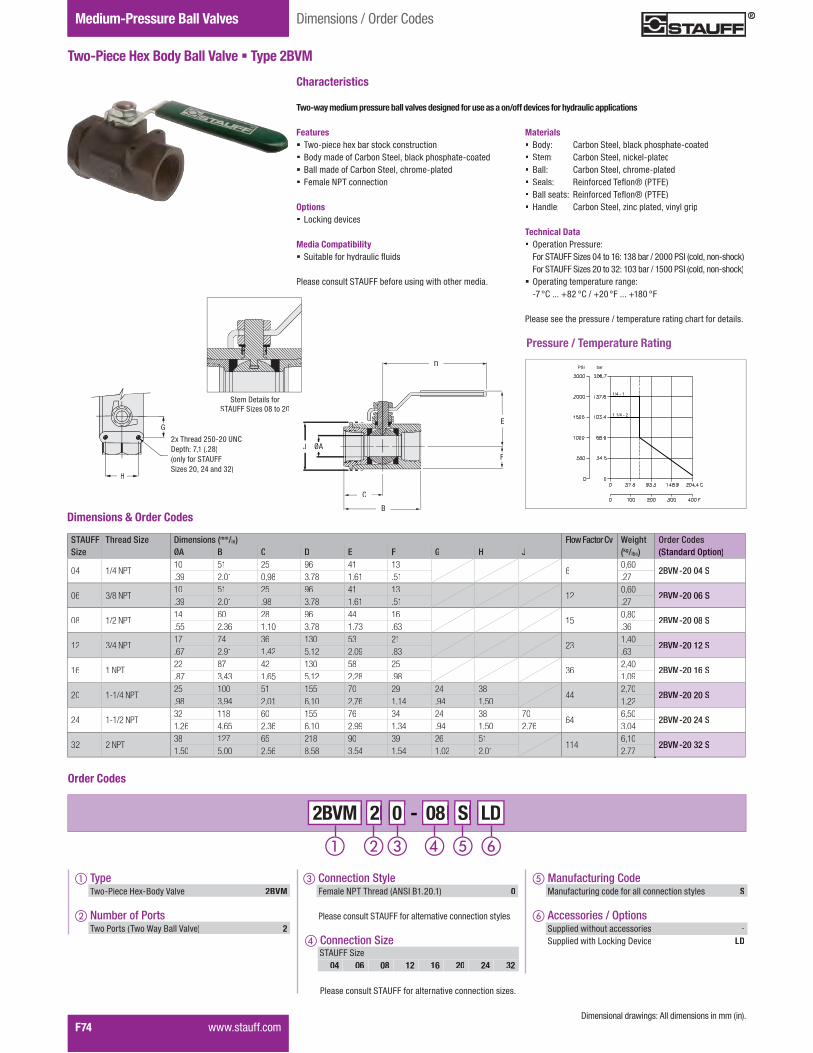
F74� �����������
Gauge Isolator ValvesTwo-Way Ball ValvesMedium-Pressure Ball Valves Dimensions / Order Codes
Two-Piece Hex Body Ball Valve � Type 2BVM
STAUFF Thread Size Dimensions (mm/in) Flow Factor Cv Weight Order CodesSize ØA B C D E F G H J (kg/lbs) (Standard Option)
04 1/4 NPT10 51 25 96 41 13
60,60
2BVM-20 04 S.39 2.01 0,98 3.78 1.61 .51 .27
06 3/8 NPT10 51 25 96 41 13
120,60
2BVM-20 06 S.39 2.01 .98 3.78 1.61 .51 .27
08 1/2 NPT14 60 28 96 44 16
150,80
2BVM-20 08 S.55 2.36 1.10 3.78 1.73 .63 .36
12 3/4 NPT17 74 36 130 53 21
231,40
2BVM-20 12 S.67 2.91 1.42 5.12 2.09 .83 .63
16 1 NPT22 87 42 130 58 25
362,40
2BVM-20 16 S.87 3.43 1.65 5.12 2.28 .98 1.09
20 1-1/4 NPT25 100 51 155 70 29 24 38
442,70
2BVM-20 20 S.98 3.94 2.01 6.10 2.76 1.14 .94 1.50 1.22
24 1-1/2 NPT32 118 60 155 76 34 24 38 70
646,50
2BVM-20 24 S1.26 4.65 2.36 6.10 2.99 1.34 .94 1.50 2.76 3.04
32 2 NPT38 127 65 218 90 39 26 51
1146,10
2BVM-20 32 S1.50 5.00 2.56 8.58 3.54 1.54 1.02 2.01 2.77
Dimensions & Order Codes
Order Codes
� Type ���������������������� 2BVM
� Number of Ports ���������� ������������������ 2
2 0 - 08 S 2 2 0 0 2BVM 08 08 S S LD
� Connection Size
��������������� !"##���������������������������$���
STAUFF Size04 06 08 12 16 20 24 32
� Manufacturing Code Manufacturing code for all connection styles S
� Accessories / Options��%%��������&������������� -��%%��������&�'�(��)�*���� LD
� Connection Style#������+� � &������!+�,��-�.0�-� 0
��������������� !"##��������������������������������
*�����������������)�1�!�������������������������
Pressure / Temperature Rating
Two-way medium pressure ball valves designed for use as a on/off devices for hydraulic applications
Characteristics
Features� ���%����&���2������(������������ Body made of Carbon Steel, black phosphate-coated� Ball made of Carbon Steel, chrome-plated� Female NPT connection
Options� Locking devices
Media Compatibility� �����2������&��������5����
��������������� !"##�2���������)����&���&���������
Materials� Body: Carbon Steel, black phosphate-coated� Stem: Carbon Steel, nickel-plated� Ball: Carbon Steel, chrome-plated� �����1 6�������� �5��7��� #8�� ����������1 6�������� �5��7��� #8�� Handle: Carbon Steel, zinc plated, vinyl grip
Technical Data� Operation Pressure:
For STAUFF Sizes 04 to 16: 138 bar / 2000 PSI (cold, non-shock)For STAUFF Sizes 20 to 32: 103 bar / 1500 PSI (cold, non-shock)
� Operating temperature range: �K�QR�����VW.�QR�X�V.0�Q#�����V-W0�Q#
������������&��%��������X����%�������������)�&���������������
barPSI
1/4 - 1
1 1/4 - 2
A PORTDIA
J
C
B
D
E
F
J
D
E
F
B
C
ØA
H
G
SIZES 1 1/4. 1 1/2. 2250-20 UNC-28 THO 28 DEEP
G
H
.�� &�����.\0�.0�"+R��*�%�&1�K]-���.W�(only for STAUFF Sizes 20, 24 and 32)
Stem Details forSTAUFF Sizes 08 to 20

Valv
esF
����������� F75
Dimensions / Order Codes Low-Pressure Ball Valves
Two-Piece Brass Body Valve � Type 2BVL
STAUFF Thread Size Dimensions (mm/in) Flow Factor Cv Max. Working Pressure Weight Order CodesSize ØD L A H (bar/PSI) (kg/lbs) (NPT + SAE Version)
041/4 NPT
1/4" SAE (7/16–20 UNF)
10 46 84 44,56
40 0,13 2BVL-20 04 F 2BVL-21 04 F.39 1.81 3.31 1.75 600 .30
063/8 NPT3/8" SAE (9/16–18 UNF)
10 46 84 44,57
40 0,13 2BVL-21 06 F 2BVL-21 06 F.39 1.81 3.31 1.75 600 .28
081/2 NPT1/2" SAE (3/4–16 UNF)
12,7 55 84 4819
30 0,19 2BVL-20 08 F2BVL-21 08 F.50 2.17 3.31 1.88 435 .41
123/4 NPT3/4" SAE (1-1/16–12 UN)
20 64 84 5834
30 0,30 2BVL-20 12 F 2BVL-21 12 F.78 2.52 3.31 2.28 435 .67
161 NPT1" SAE (1-5/16–12 UN)
25 76 118 6250
30 0,50 2BVL-20 16 F2BVL-21 16 F.98 2.99 4.65 2.44 435 1.09
201-1/4 NPT1-1/4" SAE (1-5/8–12 UN)
32 87 118 78104
30 0,90 2BVL-20 20 F 2BVL-21 20 F1.25 3.43 4.65 3.07 435 2.01
241-1/2 NPT1-1/2" SAE (1-7/8–12 UN)
38 93 134 85268
25 1,40 2BVL-20 24 F2BVL-21 24 F1.50 3.66 5.28 3.34 362 3.08
322 NPT2" SAE (2-1/2–12 UN)
50 110 134 96,5309
25 1,90 2BVL-20 32 F 2BVL-21 32 F1.96 4.33 5.28 3.79 362 4.18
402-1/2 NPT2-1/2–11 BSPP *
63 131 200 127,5629
25 3,60 2BVL-20 40 F2BVL-2R 40 F2.48 5.16 7.88 5.02 362 8.00
483 NPT3–11 BSPP *
75 150 200 138,51018
25 5,90 2BVL-20 48 F 2BVL-2R 48 F2.95 5.91 7.88 5.45 362 12.90
644 NPT4–11 BSPP *
100 214 260 1611622
25 10,00 2BVL-20 64 B2BVL-2R 64 B3.94 8.43 10.23 6.34 362 22.04
A AON
OFF
Dimensions & Order Codes
^������������1�� !"##���$��_0]�_W�����`_�2��������������������j��%%������&�������������!8�%����� &��q����)�%�������������w��������%���������%�������&��2���w��������q����)��������&�����!8��&�����������������2����%����� !"##���$��x.�
&��������������2����������&�����������)����� !"##�%�������%����������%�)���#KK�����#KW������������
Two-way low pressure ball valves designed for use as a on/off devices for hydraulic applications
Characteristics
Features� #��)���X�������������������&�2��������%��������� Body and ball made of Brass� Female NPT or SAE connections
�����w��������q����)�%���������$���_0]�_W�����`_�
Options� Locking devices� '���������&��� Actuator packages
�����������%�)��#K`��������������������)������������
Media Compatibility� �����2������&��������5����
��������������� !"##�2���������)����&���&���������
Materials� Body: Forged Brass for Sizes 04 to 24
Cast Brass for Sizes 32 to 64� Stem: Brass� Ball: Brass, chrome plated� �����1 �5��7��� #8�� ����������1 �5��7��� #8�� Handle: Carbon Steel, zinc plated, vinyl grip
Technical Data� Operation Pressure:
For STAUFF Sizes 04 and 06: 40 bar / 600 PSIFor STAUFF Sizes 08 to 16: 30 bar / 435 PSFor STAUFF Sizes 20 to 64: 25 bar / 362 PSI
� Operating temperature range up to +160 °C / +366 °F
A
H
Thread ØD
L
������������&��%��������X����%�������������)�&�������%�)��#K`������������% ) % )

F76� �����������
Gauge Isolator ValvesTwo-Way Ball ValvesLow-Pressure Ball Valves Dimensions / Order Codes
Two-Piece Brass Body Valve � Type 2BVL
2130
1775
1420
1066
710
355
0
15000
12500
10000
7500
5000
2500
0
150
125
100
75
50
40
30
1625
00 50 100 150 200 C
32 122 212 302 392 F
o
o
PSI KPa bar
0.145
0.072
0.007
0.014
0.001
100 1.0
50
10
5
1
0.05
0.01
0.1
0.5
1/4 3/8 1/2 3/4 1 1 1/4 1 1/2 2 2 1/2 3
4
1005010510.50.1 m3 /hr
l/s28201051.00.50.10.028
0.007 0.02 0.13 0.26 1.32 2.64 5.28 7.33 gps
PSI KPamm H2O
Pressure / Temperature RatingPressure Drop Flow Curves
Order Codes
� Type ������������������������ 2BVL
� Number of Ports ���������� ������������������ 2
2 0 - 08 F 2 2 0 0 2BVL 08 08 F F L
� Connection Size
��������������� !"##���������������������������$���
STAUFF Size04 06 08 12 16 20 24 32 40 48 64
� Manufacturing Code Manufacturing code for all connection styles F
� Accessories / Options��%%��������&������������� -��%%��������&�'�(��)�*���� L��%%��������&�'���������& S��%%��������&�'�(��)�*���������'���������& X
� Connection Style#������+� � &������!+�,��-�.0�-� 0Female UN/UNF Thread (SAE J 514) 1|���w���#����������� &������*,+�,�q�..W�(For connection sizes 40, 48 and 64 only) R
��������������� !"##��������������������������������

Valv
esF
Characteristics� '��(�#����q�6��)�������)����_}����&�������������R���������q%�����1
Socket Weld, Hose Barb (Straight 45° & 90°) or Split Flange� Carbon Steel Construction� '�(�+���*���)�����%��w����&������������)��������������8���������������*���)����������� Buna-N Seals
Options� Viton Seals� Step Sizes Available (Consult Factory)� 1/2 or 3/4 Sizes Available (Consult Factory)
�����������1�!���q����)��������&�����2����2�������2����������2���
Dimensions / Order Codes Low-Pressure Ball Valves
AB
CD
Locking Ring
AB
C
A
BC
Port Adaptors
����������� F77
STAUFF Thread Size Dimensions (mm/in) Order CodesSize A B C D (Standard Option)
16 / 1“ 1-5/16–12 UN - 2B22.4 6,4 33,8 41,4 SWA-16.88 .25 1.33 1.63
20 / 1-1/4“ 1-5/8–12 UN - 2B22.4 6,4 42,4 50,8 SWA-20.88 .25 1.67 2.00
24 / 1-1/2“ 1-7/8–12 UN - 2B22.4 6,4 48,5 57,2 SWA-24.88 .25 1.91 2.25
32 / 2“ 2-1/2–12 UN -2B25,4 6,4 60,7 69,9 SWA-321.00 .25 2.39 2.75
40 2-1/2“ 2-1/2–11 BSPP38,1 .50 73,4 82,6 SWA-401.50 12,7 2.89 3.25
48 / 3“ 3–11 BSPP38,1 .50 89,2 95,3 SWA-481.50 12,7 3.51 3.75
64 / 4“ 4–11 BSPP38,1 .50 114,6 120,7 SWA-641.50 12,7 4.51 4.75
STAUFF Thread Size Dimensions (mm/in) Order CodesSize A B C (Standard Option)
16 / 1“ 1-5/16–12 UN - 2B9,7 34,8 21,3 HA-16.38 1.37 .84
20 / 1-1/4“ 1-5/8–12 UN - 2B10,2 48,3 26,9 HA-20.40 1.90 1.06
24 / 1-1/2“ 1-7/8–12 UN - 2B10,2 49,3 31,8 HA-24.40 1.94 1.25
32 / 2“ 2-1/2–12 UN -2B10,4 61,7 43,2 HA-32.41 2.43 1.70
40 2-1/2“ 2-1/2–11 BSPP11,4 78,5 54,6 HA-40.45 3.09 2.15
48 / 3“ 3–11 BSPP11,4 91,9 67,3 HA-48.45 3.62 2.65
64 / 4“ 4–11 BSPP11,4 124,5 92,7 HA-64.45 4.90 3.65
STAUFF Thread Size Dimensions (mm/in) Order CodesSize (Standard Option)
16 / 1“ 1-5/16–12 UN - 2B61,0 25,4 44,5 SAS-162.40 1.00 1.75
20 / 1-1/4“ 1-5/8–12 UN - 2B69,1 31,8 50,8 SAS-202.72 1.25 2.00
24 / 1-1/2“ 1-7/8–12 UN - 2B69,1 38,1 60,5 SAS-242.72 1.50 2.38
32 / 2“ 2-1/2–12 UN -2B75,4 50,8 71,4 SAS-322.97 2.00 2.81
40 2-1/2“ 2-1/2–11 BSPP80,8 63,5 84,1 SAS-403.18 2.50 3.31
48 / 3“ 3–11 BSPP80,8 76,2 101,6 SAS-483.18 3.00 4.00
64 / 4“ 4–11 BSPP87,4 101,6 127,0 SAS-643.44 4.00 5.00
Swivel Socket Weld Adaptor � Type SWA
SAE Swivel to Hose Barb Adaptor � Type HA
SAE to Split Flange (Code 61) Adaptor � Type SAS

F78� �����������
Gauge Isolator ValvesTwo-Way Ball ValvesLow-Pressure Ball Valves Dimensions / Order Codes
A
B
C
AB
C
D
A
B
C
LockingRing
A
B
C
Locking Ring
Port Adaptors
STAUFF Thread Size Dimensions (mm/in) Order CodesSize A B C (Standard Option)
16 / 1“ 1-5/16–12 UN - 2B41,4 22,4 38,1 SNN-161.63 .88 1.50
20 / 1-1/4“ 1-5/8–12 UN - 2B47,8 22,4 39,6 SNN-201.88 .88 1.56
24 / 1-1/2“ 1-7/8–12 UN - 2B57,2 22,4 39,6 SNN-242.25 .88 1.56
32 / 2“ 2-1/2–12 UN -2B69,9 22,4 44,5 SNN-322.75 .88 1.75
40 2-1/2“ 2-1/2–11 BSPP79,5 25,4 44,5 SNN-403.13 1.00 1.75
48 / 3“ 3–11 BSPP98,6 25,4 44,5 SNN-483.88 1.00 1.75
64 / 4“ 4–11 BSPP124,0 25,4 44,5 SNN-644.88 1.00 1.75
A
B CNPT THREAD "N"
Locking Ring
SAE Swivel to NPT Female Adaptor � Type SNN
STAUFF Thread Size Dimensions (mm/in) Order CodesSize A B C (Standard Option)
16 / 1“ Code 6144,5 66,8 21,3 HAS-161.75 2.63 .84
20 / 1-1/4“ Code 6150,8 76,2 26,9 HAS-202.00 3.00 1.06
24 / 1-1/2“ Code 6160,5 76,2 31,8 HAS-242.38 3.00 1.25
32 / 2“ Code 6171,4 82,6 43,2 HAS-322.81 3.25 1.70
40 2-1/2“ Code 6184,1 101,6 54,6 HAS-403.31 4.00 2.15
48 / 3“ Code 61101,6 114,3 67,3 HAS-484.00 4.50 2.65
64 / 4“ Code 61127,0 127,0 92,7 HAS-645.00 5.00 3.65
Split Flange to Hose Barb Adaptor � Type HAS
STAUFF Dimensions (mm/in) Order CodesSize A B C D (Standard Option)
16 / 1“69,9 25,4 44,5 92,2 HAS90-162.75 1.00 1.75 3.63
20 / 1-1/4“82,6 31,8 50,8 117,6 HAS90-203.25 1.25 2.00 4.63
24 / 1-1/2“165,1 38,1 60,5 127,0 HAS90-246.50 1.50 2.38 5.00
32 / 2“108,0 50,8 71,4 158,8 HAS90-324.25 2.00 2.81 6.25
40 2-1/2“139,7 63,5 84,1 200,2 HAS90-405.50 2.50 3.31 7.88
48 / 3“162,1 76,2 101,6 228,6 HAS90-486.38 3.00 4.00 9.00
64 / 4“203,2 101,6 127,0 289,1 HAS90-648.00 4.00 5.00 11.38
Split Flange to Hose Barb Elbow 90° Adaptor � Type HAS90
STAUFF Thread Size Dimensions (mm/in) Order CodesSize A B C (Standard Option)
16 / 1“ 1-5/16–12 UN - 2B88,9 50,8 25,4 HA45-163.50 2.00 1.00
20 / 1-1/4“ 1-5/8–12 UN - 2B108,0 63,5 31,8 HA45-204.25 2.50 1.25
24 / 1-1/2“ 1-7/8–12 UN - 2B111,3 63,5 38,1 HA45-244.38 2.50 1.50
32 / 2“ 2-1/2–12 UN -2B136,7 79,5 50,8 HA45-325.38 3.13 2.00
40 2-1/2“ 2-1/2–11 BSPP177,8 101,6 63,5 HA45-407.00 4.00 2.50
48 / 3“ 3–11 BSPP203,2 117,9 76,2 HA45-488.00 4.64 3.00
64 / 4“ 4–11 BSPP241,3 139,7 101,6 HA45-649.50 5.50 4.00
SAE Swivel to Hose Barb Elbow 45° Adaptor � Type HA45
SAE Swivel to Hose Barb Elbow 90° Adaptor � Type HA90 STAUFF Thread Size Dimensions (mm/in) Order CodesSize A B C (Standard Option)
16 / 1“ 1-5/16–12 UN - 2B60,5 92,2 25,4 HA90-162.38 3.63 1.00
20 / 1-1/4“ 1-5/8–12 UN - 2B69,9 114,3 31,8 HA90-202.75 4.50 1.25
24 / 1-1/2“ 1-7/8–12 UN - 2B79,5 127,0 38,1 HA90-243.13 5.00 1.50
32 / 2“ 2-1/2–12 UN -2B101,6 158,8 50,8 HA90-324.00 6.25 2.00
40 2-1/2“ 2-1/2–11 BSPP133,4 204,7 63,5 HA90-405.25 8.06 2.50
48 / 3“ 3–11 BSPP152,4 230,1 76,2 HA90-486.00 9.06 3.00
64 / 4“ 4–11 BSPP196,9 289,1 101,6 HA90-647.75 11.38 4.00
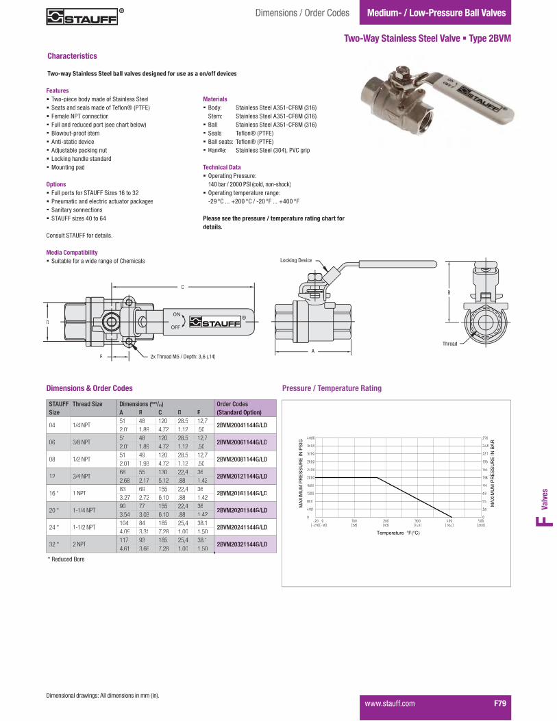
Valv
esF
����������� F79
Dimensions / Order Codes Medium- / Low-Pressure Ball Valves
Two-Way Stainless Steel Valve � Type 2BVM
"B"
SIZE (NPT THD.)
"A"
LOCKING DEVICE
Pressure / Temperature Rating
STAUFF Thread Size Dimensions (mm/in) Order CodesSize A B C D E (Standard Option)
04 1/4 NPT51 48 120 28.5 12,7
2BVM20041144G/LD2.01 1.89 4.72 1.12 .50
06 3/8 NPT51 48 120 28.5 12,7
2BVM20061144G/LD2.01 1.89 4.72 1.12 .50
08 1/2 NPT51 49 120 28.5 12,7
2BVM20081144G/LD2.01 1.93 4.72 1.12 .50
12 3/4 NPT68 55 130 22,4 36
2BVM20121144G/LD2.68 2.17 5.12 .88 1.42
16 * 1 NPT83 69 155 22,4 36
2BVM20161144G/LD3.27 2.72 6.10 .88 1.42
20 * 1-1/4 NPT90 77 155 22,4 36
2BVM20201144G/LD3.54 3.03 6.10 .88 1.42
24 * 1-1/2 NPT104 84 185 25,4 38.1
2BVM20241144G/LD4.09 3.31 7.28 1.00 1.50
32 * 2 NPT117 93 185 25,4 38.1
2BVM20321144G/LD4.61 3.66 7.28 1.00 1.50
Dimensions & Order Codes
*�����������������)�1�!�������������������������
"C"
"E"
"D"
2x M5 THD x 0.14 [3.6] DEEP
ON
OFF
Thread
B
A
Locking Device
D
C
.�� &�����|\�X�*�%�&1�x]`���-_�E
* Reduced Bore
Two-way Stainless Steel ball valves designed for use as a on/off devices
Characteristics
Features� ���%����2��������������������������� ����������������������� �5��7��� #8�� Female NPT connection� #���������������%���������&����2������ ��������%��������� Anti-static device� !������2���%�(��)����� Locking handle standard� Mounting pad
Options� Full ports for STAUFF Sizes 16 to 32� Pneumatic and electric actuator packages� Sanitary sonnections� STAUFF sizes 40 to 64
R�������� !"##������������
Media Compatibility� �����2����������������)����R&������
Materials� Body: Stainless Steel A351-CF8M (316)
Stem: Stainless Steel A351-CF8M (316)� Ball: Stainless Steel A351-CF8M (316)� �����1 �5��7��� #8�� ����������1 �5��7��� #8�� Handle: Stainless Steel (304), PVC grip
Technical Data� Operating Pressure:
140 bar / 2000 PSI (cold, non-shock) � Operating temperature range: �.��QR�����V.00�QR�X��.0�Q#�����V_00�Q#
Please see the pressure / temperature rating chart fordetails.
MAXIMUMPRESSUREINPSIG
MAXIMUMPRESSUREINBAR
Temperature °F(°C)

F80� �����������
Gauge Isolator ValvesTwo-Way Ball Valves Dimensions / Order CodesMedium- / Low-Pressure Ball Valves
Two-Piece Three-Way Stainless Steel Valve � Type 2BVM3
"B"
"E"
LOCKING DEVICE
"A"
SIZE (NPT THD.)
ON
OFF
"C"
"D" SQUARE
M5 THD x 0.14 [3.6] DEEP TYP
STAUFF Thread Size Dimensions (mm/in) Order CodesSize A B C ØD E (Standard Option)
08 1/2 NPT75 42 106 36 38,1
2BVM30081144G/LD2.95 1.65 4.17 1.42 1.50
12 * 3/4 NPT86 46,5 133 42 43,8
2BVM30121144G/LD3.39 1.83 5.24 1.65 1.72
16 * 1 NPT101 55 133 42 50,3
2BVM30161144G/LD3.98 2.17 5.24 1.65 1.98
20 * 1-1/4 NPT115 63 133 50 57,5
2BVM30201144G/LD4.53 2.48 5.24 1.97 2.26
24 * 1-1/2 NPT125 74 187 50 64
2BVM30241144G/LD4.92 2.91 7.36 1.97 2.52
32 * 2 NPT149 88,3 187 70 75,5
2BVM30321144G/LD5.87 3.48 7.36 2.76 2.97
Dimensions & Order CodesPressure / Temperature Rating
ØD
ISO 5211
C
A E
B
Thread
Locking Device
����������� ����������������������� ���������������� ����������������
Characteristics
Features� ���%����2��������������������������� ����������������������� �5��7��� #8�� Female NPT connection� #���������������%���������&����2������ L bore� ��������%��������� Anti-static device� !������2���%�(��)����� Locking handle standard� Mounting pad to ISO 5211
Options� T bore� Pneumatic and electric actuator packages
R�������� !"##������������
Media Compatibility� �����2����������������)����R&������
Materials� Body: Stainless Steel A351-CF8M (316)
Stem: Stainless Steel A351-CF8M (316)� Ball: Stainless Steel A351-CF8M (316)� �����1 �5��7��� #8�� ����������1 �5��7��� #8�� Handle: Stainless Steel (304), PVC grip
Technical Data� Operating Pressure:
70 bar / 1000 PSI (cold, non-shock)Operating temperature range: �.��QR�����V.00�QR�X��.0�Q#�����V_00�Q#
Please see the pressure / temperature rating chart for details.
* Reduced Bore
MAXIMUMPRESSUREINPSIG
MAXIMUMPRESSUREINBAR
Temperature °F(°C)
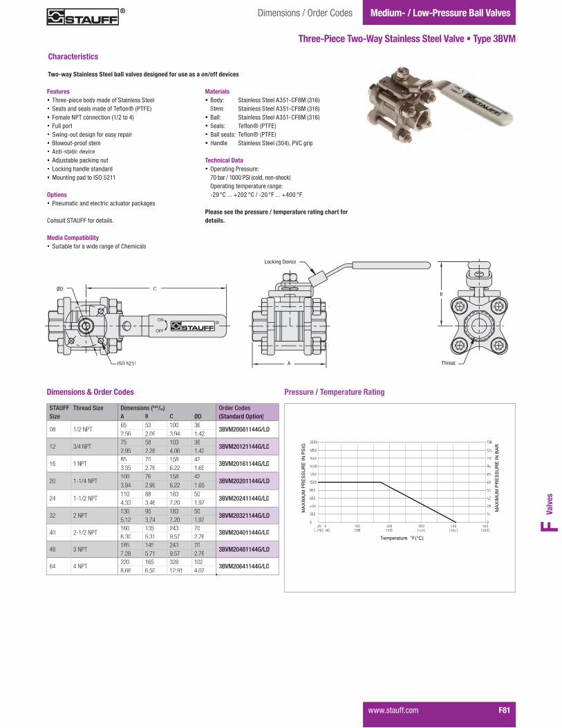
Valv
esF
"B"
SIZE (NPT THD.)
����������� F81
Dimensions / Order Codes Medium- / Low-Pressure Ball Valves
Three-Piece Two-Way Stainless Steel Valve � Type 3BVM
"A"
LOCKING DEVICE
ON
OFF
3x M5 THD x 0.14 [3.6] DEEP
"C""øD" BOLT CIRCLE
Pressure / Temperature Rating
STAUFF Thread Size Dimensions (mm/in) Order CodesSize A B C ØD (Standard Option)
08 1/2 NPT65 53 100 36
3BVM20081144G/LD2.56 2.09 3.94 1.42
12 3/4 NPT75 58 103 36
3BVM20121144G/LD2.95 2.28 4.06 1.42
16 1 NPT85 70 158 42
3BVM20161144G/LD3.35 2.76 6.22 1.65
20 1-1/4 NPT100 76 158 42
3BVM20201144G/LD3.94 2.99 6.22 1.65
24 1-1/2 NPT110 88 183 50
3BVM20241144G/LD4.33 3.46 7.20 1.97
32 2 NPT130 95 183 50
3BVM20321144G/LD5.12 3.74 7.20 1.97
40 2-1/2 NPT160 135 243 70
3BVM20401144G/LD6.30 5.31 9.57 2.76
48 3 NPT185 145 243 70
3BVM20481144G/LD7.28 5.71 9.57 2.76
64 4 NPT220 165 328 102
3BVM20641144G/LD8.66 6.50 12.91 4.02
Dimensions & Order Codes
Thread
B
A
Locking Device
ØD C
ISO 5211
Characteristics
Features� Three-piece body made of Stainless Steel� ����������������������� �5��7��� #8�� Female NPT connection (1/2 to 4)� Full port� ����)���������)������������%���� ��������%��������� Anti-static device� !������2���%�(��)����� Locking handle standard� Mounting pad to ISO 5211
Options� Pneumatic and electric actuator packages
R�������� !"##������������
Media Compatibility� �����2����������������)����R&������
Materials� Body: Stainless Steel A351-CF8M (316)
Stem: Stainless Steel A351-CF8M (316)� Ball: Stainless Steel A351-CF8M (316)� �����1 �5��7��� #8�� ����������1 �5��7��� #8�� Handle: Stainless Steel (304), PVC grip
Technical Data� Operating Pressure:
70 bar / 1000 PSI (cold, non-shock)Operating temperature range: �.��QR�����V.0.�QR�X��.0�Q#�����V_00�Q#
Please see the pressure / temperature rating chart for details.
Two-way Stainless Steel ball valves designed for use as a on/off devices
MAXIMUMPRESSUREINPSIG
MAXIMUMPRESSUREINBAR
Temperature °F(°C)

Flow Control Valves
F82� �����������
Heavy-Duty Throttle / Shut-Off Valve � Type DV (In-Line Assembly)
Dimensions / Technical Data / Order Codes
Characteristics
���������� �������������������������in both directions
Features� ���������������������������������������
NPT, SAE and BSP threaded connections� ����������������������������������������� Graduated turning knob and coded spindle
����������������������� ����������������������������������
knob to lock valve in position
Media Compatibility� ��������������������������
�����������������!""������������������������������
Materials� #���������$�������������������%&�'(&)*+
zinc/iron-plated (Fe/Zn Fe Co 8 C) and free of��1����������������2�34�%����������$����*5�����������������%&�6)(&*������������������
� Turning knob made of Polyamide (PA)� O-rings made of FPM (Viton®); NBR (Buna-N®)
and EPDM sealed version available
Consult STAUFF for ����������������������
Technical Data � 7�1��������9����$�������:� 350 bar / 5000 PSI (for all sizes)
� Operating temperature range: �@'�H2�����J&''�H2�K��6�H"�����J@&@�H"
Please see page F94 for detai�������������� ��� �
Accessories / Spare Parts Panel Mounting Kits� for DV/DRV/DVP/DRVP-8 (thread size PG 11): PMK-8-10-M� for DV/DRV/DVP/DRVP-10 (thread size PG 11): PMK-8-10-M� for DV/DRV/DVP/DRVP-12 (thread size PG 16): PMK-12-16-M� for DV/DRV/DVP/DRVP-16 (thread size PG 16): PMK-12-16-M� for DV/DRV/DVP/DRVP-20 (thread size PG 29): PMK-20-40-M� for DV/DRV/DVP/DRVP-25 (thread size PG 29): PMK-20-40-M� for DV/DRV/DVP/DRVP-30 (thread size PG 29): PMK-20-40-M� for DV/DRV/DVP/DRVP-40 (thread size PG 29): PMK-20-40-M
AB
Type + Thread Dimensions (mm/in) WeightNominal Size Options G1 G2 H1 H2 H3 B1 ØD1 ØD2 S (Max.) L1 L2 (kg/lbs)
DV-061/8 NPTG1/8 BSP
PG 764 59 18 16 24 13 3 38 19 0,12
2.52 2.32 .71 .63 .94 .51 .12 1.50 .75 .26
DV-081/4 NPT 7/16–20 UNF (1/4" SAE)
G1/4 BSP PG 11
83,5 77,5 27 25 29 19 7 48 24 0,25
3.29 3.05 1.06 .98 1.14 .75 .28 1.89 .94 .55
DV-103/8 NPT 9/16–18 UNF (3/4" SAE)
G3/8 BSP PG 11
90 83 32 30 29 19 7 58 29 0,40
3.54 3.27 1.26 1.18 1.14 .75 .28 2.28 1.14 .88
DV-121/2 NPT 3/4–16 UNF (1/2" SAE)
G1/2 BSP PG 11
109,5 99,5 38 35 38 23 7 68 34 0,60
4.31 3.92 1.50 1.38 1.50 .91 .28 2.68 1.34 1.32
DV-163/4 NPT1-1/16–12 UN (3/4" SAE)
G3/4 BSP PG 16
128,5 118,5 48 45 38 23 7 78 39 1,10
5.06 4.67 1.89 1.77 1.50 .91 .28 3.07 1.54 2.43
DV-201 NPT1-5/16–12 UN (1" SAE)
G1 BSP PG 16
159 146 55 50 49 38 10 108 54 2,40
6.26 5.75 2.17 1.97 1.93 1.50 .39 4.25 2.13 5.29
DV-251-1/4 NPT1-5/8–12 UN (1-1/4" SAE)
G1-1/4 BSP PG 29
169 156 65 60 49 38 10 108 54 2,80
6.65 6.14 2.56 2.36 1.93 1.50 .39 4.25 2.13 6.17
DV-301-1/2 NPT1-7/8–12 UN (1-1/2" SAE)
G1-1/2 BSP PG 29
175 166 75 70 49 38 10 108 54 3,50
6.89 6.54 2.95 2.76 1.93 1.50 .39 4.25 2.13 7.72
DV-402 NPT2-1/2–12 UN (2" SAE)
G2 BSP PG 29
199 186 95 90 49 38 10 120 60 6,30
7.83 7.32 3.74 3.54 1.93 1.50 .39 4.72 2.36 13.89
Dimensions
SS - 25 - V - N - 25 25 V V DV N N PM PM
Order Codes
� TypeHeavy-Duty Throttle / Shut-Off Valve (In-Line Assembly)DV
� Nominal Size DN
� Sealing MaterialFPM (Viton®) (standard option) VNBR (Buna-N®) PEPDM E
06 08 10 12 16 20 25 30 40
� Connection"������]�����������%�]�4�#&�@'�&* NFemale UN/UNF threads (SAE J514) SFemale BSP threads (ISO 228) B
� Panel Mounting NutWithout panel mounting nut (standard option) -With panel mounting nut PM
� Body / Spindle MaterialSteel (standard option) -Stainless Steel SS
ø D2 Sm
ax
G1
L 2
L1
G1
8 9 0 1 22
B1
G2
H2
(clo
sed)
H1
(ope
n)
øD1
H3
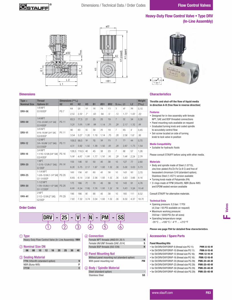
Valv
esF
Flow Control Valves
����������� F83
Dimensions / Technical Data / Order Codes
Heavy-Duty Flow Control Valve � Type DRV (In-Line Assembly)
Characteristics
���������� ������������������������������������������������������ �����������
Features� ���������������������������������������
NPT, SAE and BSP threaded connections� ����������������������������������������� Graduated turning knob and coded spindle
����������������������� ���������������������������������
knob to lock valve in position
Media Compatibility� ��������������������������
�����������������!""������������������������������
Materials� #���������$�������������������%&�'(&)*+
zinc/iron-plated (Fe/Zn Fe Co 8 C) and free of ��1����������������2�34�%����������$����*5����������������%&�6)(&*������������������
� Turning knob made of Polyamide (PA)� O-rings made of FPM (Viton®); NBR (Buna-N®)
and EPDM sealed version available
Consult STAUFF for ����������������������
Technical Data � Opening pressure: 0,5 bar / 7 PSI %6+)�����K�j)���4���������������������*
� 7�1��������9����$�������:� 350 bar / 5000 PSI (for all sizes)
� Operating temperature range: �@'�H2�����J&''�H2�K��6�H"�����J@&@�H"
Please see page F94 for detai�������������� ��� �
Accessories / Spare Parts Panel Mounting Kits� for DV/DRV/DVP/DRVP-8 (thread size PG 11): PMK-8-10-M� for DV/DRV/DVP/DRVP-10 (thread size PG 11): PMK-8-10-M� for DV/DRV/DVP/DRVP-12 (thread size PG 16): PMK-12-16-M� for DV/DRV/DVP/DRVP-16 (thread size PG 16): PMK-12-16-M� for DV/DRV/DVP/DRVP-20 (thread size PG 29): PMK-20-40-M� for DV/DRV/DVP/DRVP-25 (thread size PG 29): PMK-20-40-M� for DV/DRV/DVP/DRVP-30 (thread size PG 29): PMK-20-40-M� for DV/DRV/DVP/DRVP-40 (thread size PG 29): PMK-20-40-M
Type + Thread Dimensions (mm/in) WeightNominal Size Options G1 G2 H1 H2 H3 B1 ØD1 ØD2 S (Max.) L1 L2 (kg/lbs)
DRV-061/8 NPTG1/8 BSP PG 7
64 59 18 16 24 13 3 45 26 0,10
2.52 2.32 .71 .63 .94 .51 .12 1.77 1.02 .22
DRV-081/4 NPT 7/16–20 UNF (1/4" SAE)
G1/4 BSP PG 11
83,5 77,5 27 25 29 19 7 55 34 0,30
3.29 3.05 1.06 .98 1.14 .75 .28 2.17 1.32 .66
DRV-103/8 NPT 9/16–18 UNF (3/4" SAE)
G3/8 BSP PG 11
90 83 32 30 29 19 7 65 41 0,45
3.54 3.27 1.26 1.18 1.14 .75 .28 2.56 1.61 .99
DRV-121/2 NPT 3/4–16 UNF (1/2" SAE)
G1/2 BSP PG 11
109,5 99,5 38 35 38 23 7 73 44 0,70
4.31 3.92 1.50 1.38 1.50 .91 .28 2.87 1.73 1.54
DRV-163/4 NPT1-1/16–12 UN (3/4" SAE)
G3/4 BSP PG 16
128,5 118,5 48 45 38 23 7 88 57 1,26
5.06 4.67 1.89 1.77 1.50 .91 .28 3.46 2.24 2.78
DRV-201 NPT1-5/16–12 UN (1" SAE)
G1 BSP PG 16
159 146 55 50 49 38 10 127 77 2,60
6.26 5.75 2.17 1.97 1.93 1.50 .39 5.00 3.03 5.73
DRV-251-1/4 NPT1-5/8–12 UN (1-1/4" SAE)
G1-1/4 BSP PG 29
169 156 65 60 49 38 10 143 93 3,70
6.65 6.14 2.56 2.36 1.93 1.50 .39 5.63 3.66 8.16
DRV-301-1/2 NPT1-7/8–12 UN (1-1/2" SAE)
G1-1/2 BSP PG 29
175 166 75 70 49 38 10 143 91 4,76
6.89 6.54 2.95 2.76 1.93 1.50 .39 5.63 3.58 10.49
DRV-402 NPT2-1/2–12 UN (2" SAE)
G2 BSP PG 29
199 186 95 90 49 38 10 165 111 8,52
7.83 7.32 3.74 3.54 1.93 1.50 .39 6.50 4.37 18.78
Dimensions
- SS - 25 - V - N - 25 25 V V DRV N N PM PM
Order Codes
� Typeq����� ����"����2�������3�����%4��w������������* DRV
� Nominal Size DN
� Sealing MaterialFPM (Viton®) (standard option) VNBR (Buna-N®) PEPDM E
06 08 10 12 16 20 25 30 40
� Connection"������]�����������%�]�4�#&�@'�&* NFemale UN/UNF threads (SAE J514) SFemale BSP threads (ISO 228) B
� Panel Mounting NutWithout panel mounting nut (standard option) -With panel mounting nut PM
� Body / Spindle MaterialSteel (standard option) -Stainless Steel SS
L 1
L 2G
1S
max
ø D2
G1
8 9 0 1 22
B1
G2
H2
(clo
sed)
H1
(ope
n)
øD1
H3

Medium-Duty Throttle / Shut-Off Valve � NVH (In-Line Assembly)
Flow Control Valves Dimensions / Technical Data / Order Codes
F84� �����������
- 8 8 8 NNVH
Order Codes
� TypeMedium-Duty Throttle / Shut-Off Valve (In-Line Assembly) NVH
� STAUFF Size 08 10 12
� Connection"������]�����������%�]�4�#&�@'�&* NFemale UN/UNF thread (SAE J514) S
"������#�����������%4�x�@@{*����������������������
Characteristics
���������� �������������������������in both directions
Features� ���������������������������������������
NPT and SAE threaded connections; female #������������������������������������������
� Ideal for medium-duty applications� ���������������9������������������������� |�����������������9��������������������������� ����������������������������������
knob to lock valve in position
Media Compatibility� ��������������������������
�����������������!""������������������������������
Materials� Body made of Steel, nickel-plated� Internal components made of Stainless Steel� O-rings made of NBR (Buna-N®);
FPM (Viton®) sealed version available� ������1����������������������"}
Consult STAUFF for ����������������������
Technical Data
� 7�1��������9����$�������:� 350 bar / 5000 PSI (for all sizes)
� Operating temperature range: �~6�H2�����J&@&�H2�K��~'�H"�����J@)'�H"
Accessories / Spare Parts Panel Mounting Kits� ���]3qK"2qK]3�K"27�'{�%������������7&(1&*: PMK-8-T�����]3qK"2qK]3�K"27�&'�%������������7@'1&*: PMK-810-T�����]3qK"2qK]3�K"27�&@�%������������7@)1&+)*: PMK-1012-T
Type + Thread Dimensions (mm/in) WeightNominal Size Options A B C D E F Thread H L � CH (kg/lbs)
NVH-8
1/4 NPT 7/16–20 UNF (1/4“ SAE)
12 46 61 4,5 22M17x1
52,5 17 0,12.47 1.81 2.40 .18 .87 2.07 .67 .26
NVH-10
3/8 NPT 9/16–18 UNF (3/4“ SAE)
13 55 74 7 27M20x1
63 22 0,23.51 2.17 2.91 .28 1.06 2.48 .97 .51
NVH-12
1/2 NPT
3/4–16 UNF (1/2“ SAE)
16 82 85,5 10 33M25x1,5
72 27 0,45.63 2.76 3.37 .39 1.30 2.83 1.06 1.00
Dimensions
251 388
H
A � CH
B
C
D
L
E
F

Valv
esF
Medium-Duty Flow Control Valve � Type FCH (In-Line Assembly)
Flow Control ValvesDimensions / Technical Data / Order Codes
������������ F85
Order Codes
- 8 8 8 NFCH
� Type� ������������������������ (In-Line Assembly) FCH
� STAUFF Size 08 10 12
� Connection� ��� �������� �����!�"#�$%�&'�%* NFemale UN/UNF thread (SAE J514) S
� ��� �$"����� �����#"+�&&,*�������.� ���� 0� ���
B A
Characteristics
���������� ������������������������������������������������������ �����������
Features� � ��2� ����������� ���� �.��������� ��� �
NPT and SAE threaded connections; female $"����� �� ���� �����������.� ���� 0� ��
� Ideal for medium-duty applications� ��� ��������2�3����������.� ���� 0� ��� 6������ ��������2�3�.�������� ��������7�� " ���� ����� ������� ���������2
knob to lock valve in position
Media Compatibility� "����.� �������������7����
�� �� �������"�!8���. �� �����2�������� ��� ����
Materials� Body made of Steel, nickel-plated� Internal components made of Stainless Steel � O-rings made of NBR (Buna-N®);
FPM (Viton®) sealed version available� !���� :����������2���� ������<
Consult STAUFF for ��� ������ ���� ������
Technical Data
� ��:�������3��2�=� ���� >� 350 bar / 5000 PSI (for all sizes)
� Operating temperature range: �HK�Q������W%&%�Q��X��H'�Q������W&Y'�Q�
Accessories / Spare Parts Panel Mounting Kits� �����ZX��ZX��[X����',����� �����\ ��%]:%*> PMK-8-T� �����ZX��ZX��[X����%'����� �����\ ��&':%*> PMK-810-T�������ZX��ZX��[X����%&����� �����\ ��&Y:%^Y*> PMK-1012-T
E
DL
F
H
A
G
C
B
CH
Type + Thread Dimensions (mm/in) WeightNominal Size Options A B C D E F G Thread H L � CH (kg/lbs)
FCH-8
1/4 NPT 7/16–20 UNF (1/4“ SAE)
12 56 61 4,5 22 36M17x1
52,5 17 0,14.47 2.20 2.40 .18 .87 1.42 2.07 .67 .31
FCH-10
3/8 NPT 9/16–18 UNF (3/4“ SAE)
13 64,5 74 7 27 41,5M20x1
63 22 0,26.51 2.54 2.91 .28 1.06 1.63 2.48 .97 .57
FCH-12
1/2 NPT 3/4–16 UNF (1/2“ SAE)
16 87 85,5 10 33 57M25x1,5
72 27 0,49.63 3.42 3.37 .39 1.30 2.24 2.83 1.06 1.08
Dimensions

Medium-Pressure Brass Throttle / Shut-Off Valve � Type NVM (In-Line Assembly)
Flow Control Valves Dimensions / Technical Data / Order Codes
F86� ������������
- 8 8 8 NNVM
Order Codes
� TypeMedium-Pressure Throttle / Shut-Off Valve (In-Line Assembly) NVM
� STAUFF Size 08 10 12
� Connection� ��� �������� �����!�"#�$%�&'�%*�����������=���* NFemale UN/UNF thread (SAE J514) SFemale BSP threads (ISO 228) B
Characteristics
���������� �������������������������in both directions
Features� � ��2� ����������� ���� �.��������� ��� �
NPT, SAE and BSP threaded connections� Ideal for medium-pressure applications� ��� ��������2�3����������.� ���� 0� ��� 6������ ��������2�3�.�������� ��������7�� " ���� ����� ������� ���������2�
knob to lock valve in position
Media Compatibility� "����.� �������������7����
�� �� �������"�!8���. �� �����2�������� ��� ����
Materials� Body made of Brass, nickel-plated� Internal components made of Stainless Steel� O-rings made of NBR (Buna-N®);
FPM (Viton®) sealed version available� !���� :����������2���� ������<
Consult STAUFF for ��� ������ ���� ������
Technical Data
� ��:�������3��2�=� ���� >� 200 bar / 3000 PSI (for all sizes)
� Operating temperature range: �HK�Q������W%&%�Q��X��H'�Q������W&Y'�Q�
Accessories / Spare Parts Panel Mounting Kits� �����ZX��ZX��[X����',����� �����\ ��%]:%*> PMK-8-T�������ZX��ZX��[X����%'����� �����\ ��&':%*> PMK-810-T�������ZX��ZX��[X����%&����� �����\ ��&Y:%^Y*> PMK-1012-T
B A
Type + Thread Dimensions (mm/in) WeightNominal Size Options A B C D E F Thread H L � CH (kg/lbs)
NVM-8
1/4 NPT 7/16–20 UNF (1/4“ SAE)
1/4 BSP
12 46 57 4,5 22M17x1
11 17 0,12.47 1.81 2.24 .18 .87 .43 .67 .26
NVM-10
3/8 NPT 9/16–18 UNF (3/4“ SAE)
3/8 BSP
13 55 69 7 27M20x1
15 22 0,23.51 2.17 2.72 .28 1.06 .59 .97 .51
NVM-12
1/2 NPT 3/4–16 UNF (1/2“ SAE)
1/2 BSP
16 70 82 10 33M25x1,5
19 27 0,45.63 2.76 3.23 .39 1.30 .75 1.06 1.00
Dimensions
E
F
DL
H
A CH
B
C
G

Valv
esF
AD
E F
L
H
G
C
CH
B
Medium-Pressure Brass Flow Control Valve � Type FCM (In-Line Assembly)
Flow Control ValvesDimensions / Technical Data / Order Codes
������������ F87
Order Codes
- 8 8 8 NFCM
� Type� ������� ���� ��������������� (In-Line Assembly) FCM
� STAUFF Size 08 10 12
� Connection� ��� �������� �����!�"#�$%�&'�%*�����������=���* NFemale UN/UNF thread (SAE J514) SFemale BSP threads (ISO 228) B
Characteristics
���������� ������������������������������������������������������ �����������
Features� � ��2� ����������� ���� �.��������� ��� �
NPT, SAE and BSP threaded connections� Ideal for medium-pressure applications� ��� ��������2�3����������.� ���� 0� ��� 6������ ��������2�3�.�������� ��������7�� " ���� ����� ������� ���������2
knob to lock valve in position
Media Compatibility� "����.� �������������7����
�� �� �������"�!8���. �� �����2�������� ��� ����
Materials� Body made of Brass, nickel-plated� Internal components made of Stainless Steel � O-rings made of NBR (Buna-N®);
FPM (Viton®) sealed version available� !���� :����������2���� ������<
Consult STAUFF for ��� ������ ���� ������
Technical Data
� ��:�������3��2�=� ���� >� 200 bar / 3000 PSI (for all sizes)
� Operating temperature range: �HK�Q������W%&%�Q��X��H'�Q������W&Y'�Q�
Accessories / Spare Parts Panel Mounting Kits� �����ZX��ZX��[X����',����� �����\ ��%]:%*> PMK-8-T� �����ZX��ZX��[X����%'����� �����\ ��&':%*> PMK-810-T�������ZX��ZX��[X����%&����� �����\ ��&Y:%^Y*> PMK-1012-T
Type + Thread Dimensions (mm/in) WeightNominal Size Options A B C D E F G Thread H L � CH (kg/lbs)
FCM-8
1/4 NPT 7/16–20 UNF (1/4“ SAE)
1/4 BSP
12 56 61 4,5 22 11,5M17x1
11 17 0,14.47 2.20 2.40 .18 .87 .45 .43 .67 .31
FCM-10
3/8 NPT 9/16–18 UNF (3/4“ SAE)
3/8 BSP
13 64,5 74 7 27 12,5M20x1
15 22 0,26.51 2.54 2.91 .28 1.06 .49 .59 .97 .57
FCM-12
1/2 NPT 3/4–16 UNF (1/2“ SAE)
1/2 BSP
16 87 82 10 33 13M25x1,5
19 27 0,49.63 3.42 3.23 .39 1.30 .51 .75 1.06 1.08
Dimensions
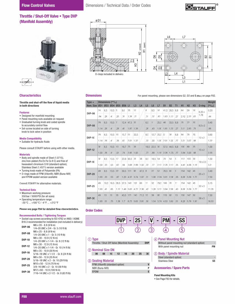
Flow Control Valves
F88� ������������
Throttle / Shut-Off Valve � Type DVP (Manifold Assembly)
Dimensions / Technical Data / Order Codes
Characteristics
���������� �������������������������in both directions
Features� Designed for manifold mounting� ��� ��������2������������.� ���� 0� ��� Graduated turning knob and coded spindle
������� ��������7�� " ���� ����� ������� ���������2�
knob to lock valve in position
Media Compatibility� "����.� �������������7����
�� �� �������"�!8���. �� �����2�������� ��� ����
Materials� $��������=���� ���� ���"� ���%�']%Y*^
zinc/iron-plated (Fe/Zn Fe Co 8 C) and free of� :���� �������������#�����������=���*w�"����� ���"� ���%�KY]%*�� �����������.�
� Turning knob made of Polyamide (PA)� O-rings made of FPM (Viton®); NBR (Buna-N®)
and EPDM sealed version available
Consult STAUFF for ��� ������ ���� ������
Technical Data � ��:�������3��2�=� ���� >� 350 bar / 5000 PSI (for all sizes)
� Operating temperature range: �&'�Q������W%''�Q��X��K�Q������W&%&�Q�
Please see page F94 for detai�������������� ��� �
Recommended Bolts / Tightening Torques� "3 ���=��� ��������2���#"+�K]x&���!�"#�X�!"�<�
$%,�H�� �� �� �������������������������� ������ ��� ��*>
DVP-06� �x�:�&'���,�,��{�N·m)
1/4|&'�8���:�HXK���6���Y��%'���}�.*
DVP-08� �x�:�&Y���,�,��{�N·m)
� %XK|&'�UNC :�% ��6���Y��%'���}�.*
DVP-10� �x�:�H'���%'�{��%&�N·m)
� %XK|&'�UNC :�%�%XK ��6���,��%&���}�.*
DVP-12� �x�:�H'���%&�{��%Y�N·m)
� %XK|&'�UNC :�%�%XK ��6���%'��%K���}�.*
DVP-16� �,�:�HY���%'�{��H'�N·m)
� YX%x|%,�UNC :�%�%X&����6���,��&K���}�.*
DVP-20� �,�:�Y'���%&�{��HY�N·m)
� YX%x|%,�UNC�:�& ��6���%'��&{���}�.*
DVP-25� �%'�:�Y'���%&�{��]'�N·m)
� HX,|%x�UNC :�& ��6���%'��Y,���}�.*
DVP-30� �%&�:�x'���%'�{��%''�N·m)
7/16|%K�8���:�&�%X&���6���,��xH���}�.*
AB
Type + Dimensions (mm/in) WeightNom. Size ØD1 ØD3 ØD4 ØD5 ØD6 L1 L3 L4 L5 L6 L7 B1 B2 T1 H1 H2 H3 O-ring (kg/lbs)
DVP-0624 6,5 10,5 5 9,8 35 19 8 9,5 16 41,5 28,5 6,8 64 59 16
6,35 x 1,78
0,20
.94 .26 .41 .20 .39 1.38 .75 .31 .37 .63 1.63 1.12 .27 2.52 2.32 .63 .44
DVP-0829 6,5 10,5 7 12,4 47,5 35 6,5 11 25,5 46 33,5 6,8 79 72 20
8,5 x 20,40
1.14 .26 .41 .28 .49 1.87 1.38 .26 .43 1.00 1.81 1.32 .27 3.11 2.83 .79 .88
DVP-1029 6,5 10,5 10 15,7 51 33,5 8,5 12,7 25,5 51 38 6,8 84 78 25
12 x 20,60
1.14 .26 .41 .39 .62 2.01 1.32 .33 .50 1.00 2.01 1.50 .27 3.31 3.07 .98 1.32
DVP-1238 6,5 10,5 13 18,7 75 38 18,5 22,5 30 57,5 44,5 6,8 100 89 25
15 x 21,00
1.50 .26 .41 .51 .74 2.95 1.50 .73 .89 1.18 2.26 1.75 .27 3.94 3.50 .98 2.20
DVP-1638 8,5 13,5 17 23,9 93,5 76 38 8,5 19,5 54 70 54 9 113 103 30
19 x 2,51,50
1.50 .33 .53 .67 .94 3.68 2.99 1.50 .33 .77 2.13 2.76 2.13 .35 4.45 4.06 1.18 3.31
DVP-2049 8,5 13,5 22 30,5 111 95 47,5 8 27 57 76,5 60 9 154 142 45
25 x 33,40
1.93 .33 .53 .87 1.20 4.37 3.74 1.87 .31 1.06 2.24 3.01 2.36 .35 6.06 5.59 1.77 7.50
DVP-2549 10,5 16,5 28,5 37,5 143 120 60 11 32 79,5 100 76 11 154 142 45
32 x 35,15
1.93 .41 .65 1.12 1.48 5.63 4.72 2.36 .43 1.26 3.13 3.94 2.99 .43 6.06 5.59 1.77 11.35
DVP-3049 13 19 35 43,5 171 143 71,5 15 39 95 115 92 13 159 147 50
38 x 37,50
1.93 .51 .75 1.38 1.71 6.73 5.63 2.81 .59 1.54 3.74 4.53 3.62 .51 6.26 5.79 1.97 16.53
Dimensions
- SS - 25 - V - 25 25 V V DVP PM PM
Order Codes
� TypeThrottle / Shut-Off Valve (Manifold Assembly) DVP
� Nominal Size DN
� Sealing MaterialFPM (Viton®) (standard option) VNBR (Buna-N®) PEPDM E
06 08 10 12 16 20 25 30
� Panel Mounting NutWithout panel mounting nut (standard option) -With panel mounting nut PM
� Body / Spindle MaterialSteel (standard option) -Stainless Steel SS
ø D1
H2
(clo
sed)
H1
(open)
H3
T1
B2
B1
D5
D3
D4
L1
L3
L4L5
D6
L6 L7
For panel mounting, please see dimensions G2, D2 and S (Max.) on page ����
O-rings included in delivery
Accessories / Spare Parts Panel Mounting Kits������������� ����������

Valv
esF - SS - 25 - V - 25 25 V V DRVP PM PM
Flow Control Valves
������� ���� F89
Dimensions / Technical Data / Order Codes
Flow Control Valve � Type DRVP (Manifold Assembly)
ABB
Characteristics
���������� ������������������������������������������������������ �����������
Features� Designed for manifold mounting� ������������������������������������ Graduated turning knob and coded spindle
������������������������ �������������������������� ��������
knob to lock valve in position
Media Compatibility� �������� ��� �������������
��������������!"#����� ������������� ��� ��������
Materials� $��������%����������� �������&'�()'*+,�-���.�����%����
&��./�����0����0+���� ����� � �1������� �������0�23�&��������%����+4����������������&'�5*)'+���������������
� Turning knob made of Polyamide (PA)� O-rings made of FPM (Viton®); NBR (Buna-N®)
and EPDM sealed version available
Consult STAUFF for ������������������
Technical Data� Opening pressure: 0,5 bar / 7 PSI
&5,* ���.�6* �3������������������+� 71��������8����%�������9
350 bar / 5000 PSI (for all sizes)� Operating temperature range:
��( :0�����;'(( :0�.��5 :������;�'� :�
Please see page F94 for detai�������������� ��� �
Recommended Bolts / Tightening Torques� ���8����%��������������������3�<�5)6�����"=�3�.�"�7>�
$'���������������� ��������������&������������������������+9
DRVP-06� 76�1��(�������&?�N·m)
1/4@�(�#=0�1��.5���A���*�&'(� �B��+
DRVP-08� 76�1��*�������&?�N·m)
� '.5@�(�UNC 1�'���A���*�&'(� �B��+
DRVP-10� 76�1��(���'(�?�&'��N·m)
� '.5@�(�UNC 1�'�'.5 ��A�����&'�� �B��+DRVP-12� 76�1��*���'��?�&'*�N·m)� '.5@�(�UNC 1�'�'.� ��A���'(�&'5� �B��+DRVP-16� 7��1�*(���'(�?�&�(�N·m)� *.'6@'��#=0�1�����A�����&�5� �·lb)DRVP-20� 7��1�**���'��?�&�*�N·m)� *.'6@'��#=0�1���'.5���A���'(�&�?� �·lb)DRVP-25� 7'(�1�6(���'��?�&)(�N·m)� �.�@'6�#=0�1���'.����A���'(�&*�� �·lb)DRVP-30� 7'��1��*���'(�?�&'((�N·m)
7/16@'5�1���'.����A�����&6�� �B��+DRVP-40� 7'��1�'((���'��?�&'�(�N·m)
7/16@'5�1�5���A���'(�&)(� �B��+
Dimensions
Order Codes
� Type�����0�������2����&7�� ����"�������+ DRVP
� Nominal Size DN
� Sealing MaterialFPM (Viton®) (standard option) VNBR (Buna-N®) PEPDM E
06 08 10 12 16 20 25 30 40
� Panel Mounting NutWithout panel mounting nut (standard option) -With panel mounting nut PM
� Body / Spindle MaterialSteel (standard option) -Stainless Steel SS
H2
(clo
sed
)
H1
(op
en)
H3
L9øD1
T1 D6
B2
B1
D5
D3
D4
L1
L3
L4L5
L6 L7
L8
Type + Dimensions (mm/in) WeightNom. Size ØD1 ØD3 ØD4 ØD5 ØD6 L1 L3 L4 L5 L6 L7 L8 L9 B1 B2 T1 H1 H2 H3 O-ring (kg/lbs)
DRVP-0624 6,5 10,5 5 9,8 41,5 19 6,4 8 16 47 13,5 41,5 28,5 6,8 64 59 16 6,35 x
1,78
0,26
.94 .26 .41 .20 .39 1.63 .75 .25 .31 .63 1.85 .53 1.63 1.12 .27 2.52 2.32 .63 .57
DRVP-0829 6,5 10,5 7 12,4 63,5 35 14,2 18,7 25,5 70 31 46 33,5 6,8 79 72 20
8,5 x 20,50
1.14 .26 .41 .28 .49 2.50 1.38 .56 .74 1.00 2.76 1.22 1.81 1.32 .27 3.11 2.83 .79 1.10
DRVP-1029 6,5 10,5 10 15,7 70 33,5 18 22,0 25,5 75 29,5 51 38 6,8 84 78 25
12 x 20,80
1.14 .26 .41 .39 .62 2.76 1.32 .71 .87 1.00 2.95 1.16 2.01 1.50 .27 3.31 3.07 .98 1.76
DRVP-1238 6,5 10,5 13 18,7 80 38 21 25,0 30 86 36,5 57,5 44,5 6,8 107 96 32
15 x 21,20
1.50 .26 .41 .51 .74 3.15 1.50 .83 .98 1.18 3.39 1.44 2.26 1.75 .27 4.21 3.78 1.26 2.65
DRVP-1638 8,5 13,5 17 23,9 104 76 38 14 25,4 54 110 49 70 54 9 128 118 45
19 x 2,52,50
1.50 .33 .53 .67 .94 4.09 2.99 1.50 .55 1.00 2.13 4.33 1.93 2.76 2.13 .35 5.04 4.65 1.77 5.51
DRVP-2049 8,5 13,5 22 30,5 127 95 47,5 16 35 57 133 49 76,5 60 9 159 147 50
25 x 33,90
1.93 .33 .53 .87 1.20 5.00 3.74 1.87 .63 1.38 2.24 5.24 1.93 3.01 2.36 .35 6.26 5.79 1.97 8.60
DRVP-2549 10,5 16,5 28,5 37,5 165 120 60 15 35,6 79,5 171 77 100 76 11 164 152 55
32 x 36,70
1.93 .41 .65 1.12 1.48 6.50 4.72 2.36 .59 1.40 3.13 6.73 3.03 3.94 2.99 .43 6.46 5.98 2.17 14.77
DRVP-3049 13 19 35 43,5 186 143 71,5 15 38,8 95 192 85 115 92 13 184 172 75
38 x 311,00
1.93 .51 .75 1.38 1.71 7.32 5.63 2.81 .59 1.53 3.74 7.56 3.35 4.53 3.62 .51 7.24 6.77 2.95 24.25
DRVP-4049 13 19 47,5 57,5 192 133,5 67,5 16 41,5 89 197 64 140 111 13 209 197 100
52 x 318,80
1.93 .51 .75 1.87 2.26 7.56 5.25 2.66 .63 1.63 3.50 7.76 2.52 5.51 4.37 .51 8.23 7.76 3.94 41.45
For panel mounting, please see dimensions G2, D2 and S (Max.) on page ����
O-rings included in delivery
Accessories / Spare Parts Panel Mounting Kits������������� ����������
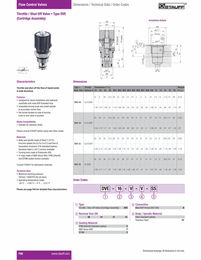
Flow Control Valves
F90� ������� ����
Throttle / Shut-Off Valve � Type DVE (Cartridge Assembly)
Dimensions / Technical Data / Order Codes
Characteristics
���������� �������������������������in both directions
Features� Designed for direct installation into hydraulic
��� �������� �����$��� ����������� Graduated turning knob and coded spindle
������������������������ �������������������������� ���������
knob to lock valve in position
Media Compatibility� �������� ��� �������������
��������������!"#����� ������������� ��� ��������
Materials� $��������%����������� �������&'�()'*+,
zinc/iron-plated (Fe/Zn Fe Co 8 C) and free of �1������� �������0�23�&��������%����+4����������������&'�5*)'+���������������
� Turning knob made of Polyamide (PA)� O-rings made of NBR (Buna-N®); FPM (Viton®)
and EPDM sealed version available
Consult STAUFF for ������������������
Technical Data � 71��������8����%�������9� 350 bar / 5000 PSI (for all sizes)
� Operating temperature range: ��(�:0�����;'((�:0�.��5�:������;�'��:�
Please see page F94 for detai�������������� ��� �
AB
Type + Thread Dimensions (mm/in) WeightNom. Size Options G H1 H2 H3 H4 ØD1 ØD2 ØD3 ØD4 ØD5 ØD6 ØD7 ØD8 SW T2 T3 T4 T5 T6 (kg/lbs)
DVE-08 G1/2 BSP
47 41 28 12,0 29 32 24 14 14 5 5 5 27 1,9 14 17,5 15 29 0,15
1.85 1.61 1.08 .47 1.14 1.26 .94 .55 .55 .20 .20 .20 1.06 .07 .55 .69 .59 1.14 .33
DVE-10 G1/2 BSP
64 54 31 14,5 38 32 24 16 16 8 6 8 27 1,9 14 20,5 17 33 0,25
2.52 2.13 1.21 .57 1.50 1.26 .94 .63 .63 .31 .24 .31 1.06 .07 .55 .81 .67 1.30 .55
DVE-12 G3/4 BSP
65 55 40 17,5 38 37 30 19 19 10 8 10 32 1,9 21 29,0 24 43 0,50
2.56 2.17 1.57 .69 1.50 1.46 1.18 .75 .75 .39 .31 .39 1.26 .07 .83 1.14 .94 1.69 1.10
DVE-16 G1 BSP
65 55 44 21,1 38 47 36 27 27 12 8 12 41 1,9 21 30,0 24 47 0,70
2.56 2.17 1.71 .83 1.50 1.85 1.42 1.06 1.06 .47 .31 .47 1.61 .07 .83 1.18 .94 1.85 1.54
Dimensions
- 16 - V - V - 16 16 V V DVE V V SS
Order Codes
� ConnectionMale BSP thread (ISO 228) B
� Body / Spindle MaterialSteel (standard option) -Stainless Steel SS
� TypeThrottle / Shut-Off Valve (Cartridge Assembly) DVE
� Nominal Size DN
� Sealing MaterialFPM (Viton®) (standard option) VNBR (Buna-N®) PEPDM E
08 10 12 16
T3
T4
6.3
1.5
x 20°
1
T2+
0.1
øD8
3.2
øD6
T5
T6
øD4H8
G (ISO228)
øD3+0.1
øD2
3.2
Installation Details
G (ISO 228)
H2 (
clo
sed)
H1 (
open)
H4
H3
ø D1
SW
øD7
øD5
G
����������� ������������������������������
H2 (c
lose
d)
H1 (o
pen)
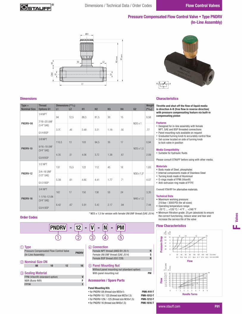
Valv
esF
Flow Control Valves
������������� F91
Dimensions / Technical Data / Order Codes
Characteristics
���������� ������������������������������������������������������ �����������with pressure compensating feature via built-incompensating piston
Features� ����������� �������������������������
NPT, SAE and BSP threaded connections� �������������������������� ������� � �������� ���������������� �������� �� ��� !����� ���������������������� ���������
to lock valve in position
Media Compatibility� !�������� ���� ���� ����
������������!"�#$$����� ����������������� ������
Materials� Body made of Steel, phosphated� Internal components made of Stainless Steel � Turning knob made of Aluminium� O-rings made of FPM (Viton®)� ������%� ������ ������������"$&
Consult STAUFF for �� ��������� ���
Technical Data � '%������� �����( ���� ��� 210 bar / 3000 PSI (for all sizes)
� Operating temperature range: �)*�+,�����-.)*�+,�/��0�+$�����-)01�+$
� '�������2� ������ ����)3�4��5������6�������� �� ������ ���������������7� �������� ������ ���� increase the service life of the valve
Flow Characteristics
Dimensions
- 12 - V - N -1212 VVPNDRV NN PM
Order Codes
� Connection$����8�"��� ���5�8!9�:.�)*�.6 NFemale UN/UNF thread (SAE J514) SFemale BSP thread (ISO 228) B
� Panel Mounting NutWithout panel mounting nut (standard option) -With panel mounting nut PM
� Type� ���� ��,��(�������$���,��� ��;��(In-Line Assembly)
PNDRV
� Nominal Size DN
� Sealing MaterialFPM (Viton®) (standard option) VNBR (Buna-N®) PEPDM E
08 10 12 16
Type + Thread Dimensions (mm/in) WeightNominal Size Options G1 L1 L2 H1 H2 H3 H4 G2 (kg/lbs)
PNDRV-08
1/4 NPT 7/16–20 UNF (1/4" SAE)
G1/4 BSP
94 12,5 88,5 81,5 30 15
M20 x 1
0,58
3.70 .49 3.48 3.21 1.18 .59 .77
PNDRV-10
3/8 NPT 9/16–18 UNF (3/4" SAE)
G3/8 BSP
110,5 13 103 94,5 35 17
M25 x 1,5
0,94
4.35 .51 4.06 3.72 1.38 .67 2.09
PNDRV-12
1/2 NPT 3/4–16 UNF (1/2" SAE)
G1/2 BSP
137 15,5 122 112 45 18
M30 x 1,5*
1,83
5.39 .61 4.80 4.41 1.77 .71 4.07
PNDRV-16
3/4 NPT 1-1/16–12 UN (3/4" SAE)
G3/4 BSP
163 17 150 138 55 24
M40 x 1,5
3,35
6.42 .67 5.91 5.43 2.17 .94 7.44
Pressure Compensated Flow Control Valve � Type PNDRV (In-Line Assembly)
B A
20
2
0
4
6
8
10-8 -10 -12 -16
�p
in b
ar
40 60 80 100 120 140 160 Q in l/min
5.3 10.6 15.8 21.1 26.4 31.7 37.0 42.2 Q in US GPM
29
58
87
116
145
�p
in P
SI
-8
-10
-12
-16
Q in l/m
in
Q in U
S G
PM
10
0
20
30
40
50
60
70
80
2.6
5.3
7.9
10.6
13.2
15.8
18.5
21.1
1 2 3 4 5 6 7 8 9
Pres
sure
Dro
pFl
ow
Flow
Handle Turns
* ')3�%�.73��� ��� ��������� female UN/UNF thread (SAE J514)
Accessories / Spare Parts Panel Mounting Kits���� ��8�<;�*1�5�� �����=��')*%.6� PMK-810-T���� ��8�<;�.*�/�.)!�5�� �����=��')3%.736� PMK-1012-T� �� ��8�<;�.)8�/��.)!�5�� �����=��'>*%.736�� PMK-1212-T� �� ��8�<;�.?�5�� �����=��'0*%.736�� PMK-1616-T
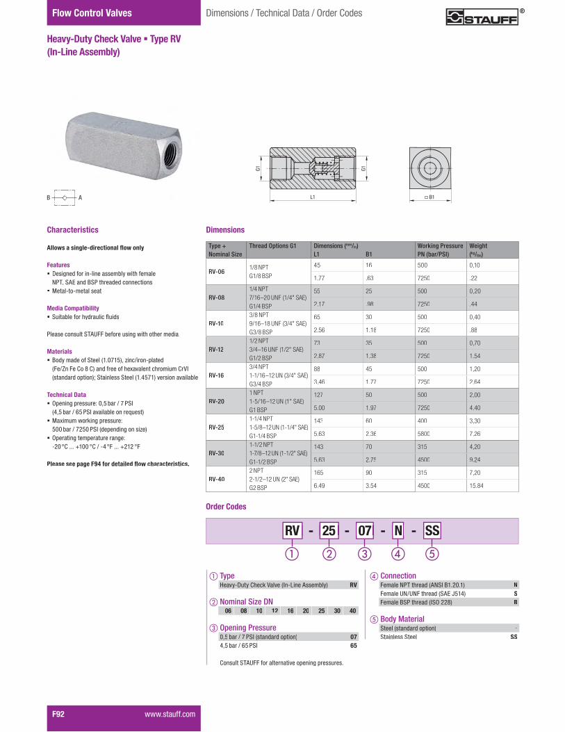
Flow Control Valves
F92� �������������
Dimensions / Technical Data / Order Codes
Characteristics
����� �����������������������
Features� ����������� �������������������������
NPT, SAE and BSP threaded connections� Metal-to-metal seat
Media Compatibility� !�������� ���� ���� ����
������������!"�#$$����� ����������������� ������
Materials� :�����������!����5.�*I.367�=���/� ���(���
5$�/J��$��,��1�,6����� ��������%������� ������, ;9�5���� ���(����6K�!�������!����5.�03I.6��� ���������
Technical Data � Opening pressure: 0,5 bar / 7 PSI 5073�� �/�?3��!9��������� ������6
� '%������� �����( ���� ��� 500 bar / 7250 PSI (depending on size)
� Operating temperature range: �)*�+,�����-.**�+,�/��0�+$�����-).)�+$
Please see page F94 for detai�������������� ��� �
B A
Heavy-Duty Check Valve � Type RV (In-Line Assembly)
Dimensions
Type + Thread Options G1 Dimensions (mm/in) Working Pressure WeightNominal Size L1 B1 PN (bar/PSI) (kg/lbs)
RV-061/8 NPTG1/8 BSP
45 16 500 0,10
1.77 .63 7250 .22
RV-081/4 NPT 7/16–20 UNF (1/4" SAE) G1/4 BSP
55 25 500 0,20
2.17 .98 7250 .44
RV-103/8 NPT 9/16–18 UNF (3/4" SAE) G3/8 BSP
65 30 500 0,40
2.56 1.18 7250 .88
RV-121/2 NPT 3/4–16 UNF (1/2" SAE)G1/2 BSP
73 35 500 0,70
2.87 1.38 7250 1.54
RV-163/4 NPT1-1/16–12 UN (3/4" SAE)G3/4 BSP
88 45 500 1,20
3.46 1.77 7250 2.64
RV-201 NPT1-5/16–12 UN (1" SAE) G1 BSP
127 50 500 2,00
5.00 1.97 7250 4.40
RV-251-1/4 NPT1-5/8–12 UN (1-1/4" SAE)G1-1/4 BSP
143 60 400 3,30
5.63 2.36 5800 7.26
RV-301-1/2 NPT1-7/8–12 UN (1-1/2" SAE)G1-1/2 BSP
143 70 315 4,20
5.63 2.75 4500 9.24
RV-402 NPT2-1/2–12 UN (2" SAE)G2 BSP
165 90 315 7,20
6.49 3.54 4500 15.84
- 25 - 07 - N - 25 25 07 07 RV N N SS
Order Codes
� Connection$����8�"��� ���5�8!9�:.�)*�.6 NFemale UN/UNF thread (SAE J514) SFemale BSP thread (ISO 228) B
� Body MaterialSteel (standard option) -Stainless Steel SS
� TypeHeavy-Duty Check Valve (In-Line Assembly) RV
� Nominal Size DN
� Opening Pressure0,5 bar / 7 PSI (standard option) 074,5 bar / 65 PSI 65
,������!"�#$$��� ��� �������(������( ���� ���
06 08 10 12 16 20 25 30 40
AB
G1
G1
L1 B1

Valv
esF
Flow Control Valves
������������� F93
Dimensions / Technical Data / Order Codes
Medium-Duty Check Valve � Type RVM (In-Line Assembly)
Characteristics
����� �����������������������
Features� ����������� �������������������������
NPT and BSP threaded connections� Ideal for medium-duty applications� Metal-to-metal seat
Media Compatibility� !�������� ���� ���� ����
������������!"�#$$����� ����������������� ������
Materials� Body made of Steel, zinc/nickel-coated
5� ��������%������� ������, ;96� Ball made of Stainless Steel
Technical Data � Opening pressure: 0,5 bar / 7 PSI � $���� �(������( �����������( ���� � setting of 2 bar / 30 PSI or 4 bar / 60 PSI
� '%������� �����( ���� �� 400 bar / 5800 PSI (for all sizes)
� Operating temperature range: �)*�+,�����-.**�+,�/��0�+$�����-).)�+$
Flow Characteristics
Accessories / Spare Parts Field replaceable springs� for RVM-08 (setting of 2 bar / 30 PSI): RVM-08-30� for RVM-08 (setting of 4 bar / 60 PSI): RVM-08-60� for RVM-10 (setting of 2 bar / 30 PSI): RVM-10-30� for RVM-10 (setting of 4 bar / 60 PSI): RVM-10-60� for RVM-12 (setting of 2 bar / 30 PSI): RVM-12-30� for RVM-12 (setting of 4 bar / 60 PSI): RVM-12-60� for RVM-16 (setting of 2 bar / 30 PSI): RVM-16-30� for RVM-16 (setting of 4 bar / 60 PSI): RVM-16-60
,������!"�#$$��� ��� ������( ���� �����������
B A
Dimensions
- 12 - 07 - 12 12 07 07 RVM N
Order Codes
� Opening Pressure0,5 bar / 7 PSI (standard option) 072 bar / 30 PSI 304 bar / 60 PSI 60
,������!"�#$$��� ��� �������(������( ���� ���
� Connection$����8�"��� ���5�8!9�:.�)*�.6 NFemale BSP thread (ISO 228) B
� TypeMedium-Duty Check Valve (In-Line Assembly) RVM
� Nominal Size DN08 10 12 16
Type + Thread Options G1 Dimensions (mm/in) Working Pressure WeightNominal Size L1 L2 Hex PN (bar/PSI) (kg/lbs)
RVM-081/4 NPT G1/4 BSP
63,0 12,5 22 400 0,17
2.48 .49 .87 5800 .38
RVM-103/8 NPTG3/8 BSP
69,0 12,5 27 400 0,26
2.72 .49 1.06 5800 .58
RVM-121/2 NPTG1/2 BSP
80,5 15,5 32 400 0,42
3.17 .61 1.26 5800 .93
RVM-163/4 NPTG3/4 BSP
99,5 17,0 36 400 0,61
3.92 .67 1.42 5800 1.36
20
2
0
4
6
8
10
-8 -10
-12-16
�p
in b
ar
40 60 80 100 120 140 160 Q in l/min
5.3 10.6 15.8 21.1 26.4 31.7 37.0 42.2 Q in US GPM
29
58
87
116
145
�p
in P
SI
Pres
sure
Dro
p
Flow

100
80
60
40
20
10
5
0.250.5 1 1.5 2 2.5 3 3.5 4 4.5 5 5.5 6
6.5
7
7.5
88.5
9
9.510
0 50 100 150 200 250 300 350
Throttle per revolution
100
80
60
40
20
10
5
1 20.250.5 1.5 2.5 3 3.5 4 4.5 5 5.5 6 6.5 7 7.5 8
8.5
9
9.5
10
0 25 50 75 100 125 150 175
Throttle per revolution
100
80
60
40
20
10
5
0.510.25 1.5 2 2.5 3 3.5 4 4.5 5 5.5 6 6.5 7 7.5 8 8.5 9
9.5
10
0 20 40 60 80 100 120 140
Throttle per revolution
80
60
40
20
10
5
0.25 0.5 1 1.5 2 2.5 3 3.5 4 4.5 5 5.5 66.5
7
7.5
8
0 10 20 30 40 50 60 70 75
Throttle per revolution
0.50.25 1 1.5 2 2.5 3 3.5 4 4.5
1005
80
60
40
20
10
5
0 10 20 30 40 50 60
Throttle per revolution
Flow Control Valves
F94� �����������
Nominal Flow Rate vs. Pressure Drop
�����������������
p in b
ar
12
10
8
6
4
2
Q in l/min
0,5
14
100 200 300 400 500 600
-06 -08 -10 -12 -16 -20
-25
-30
-40
p Characteristic curve free flow through check valve
Flow direction: B–A
p in P
SI
174
145
116
203
Q in US GPM26 52 78 104 130 156
58
29
7
87
DRV DRVP RV DN 06-40
DV DRV DVP DRVP DVE DN 08
pin
PSI
�p
in P
SI
1450
1160
870
580
290
145
����
0 3 ��� 8 ���� 13 16 Q in US GPM
Q in l/min
Throttle per revolution0.25 1 1.5 2 2.5 3 3.5 4
0.5
100
80
60
40
20
10
5
0 2 4 6 8 10 12 14
4.5
5
DV DRV DVP DRVP DVE DN 06
�p
in P
SI
�p
in P
SI
1450
1160
870
580
290
145
����
0 �� ��� ��� ��� ��� ��� ��� Q in US GPM
Q in l/min
DV DRV DVP DRVP DVE DN 12
�p
in P
SI
�p
in P
SI
1450
1160
870
58080
290
145
����
0 ��� ���� 16 21 32 37 Q in US GPM
Q in l/min
DV DRV DVP DRVP DVE DN 10
�p
in P
SI
�p
in P
SI
1450
1160
870
58080
290
145
����
0 3 ��� 8 ���� 16 18 Q in US GPM
Q in l/min
13 19 26
DV DRV DVP DRVP DVE DN 20-40
�p
in P
SI
�p
in P
SI
1450
1160
870
58080
290
145
����
0 13 26 39 52 78 91 Q in US GPM
Q in l/min
DV DRV DVP DRVP DVE DN 16
�p
in P
SI
�p
in P
SI
1450
1160
870
58080
290
145
����
0 ��� 13 ���� 26 39 ���� Q in US GPM
Q in l/min
���� 65
������������� ���!������������������������"���������#�$������%���"������������������������"�����&����'(��)$*"�+���"�����)��������%������&��������,*��-���.�/�� ������������������%��0����"��������"�������"�������1.2����(�

Valv
esF
����������� F95
Notes
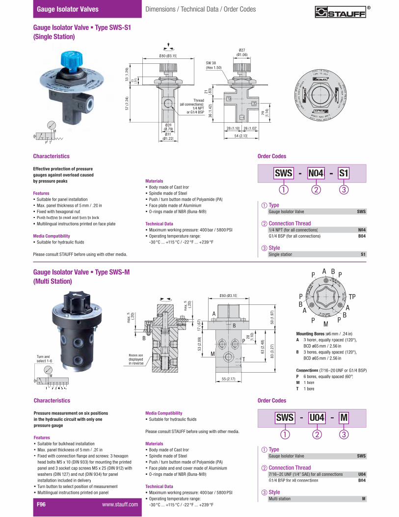
F96� �����������
Gauge Isolator Valves Dimensions / Technical Data / Order Codes
Gauge Isolator Valve � Type SWS-S1 (Single Station)
Characteristics
Effective protection of pressuregauges against overload causedby pressure peaks
Features� Suitable for panel installation� ���������������������� �������� in� ������������������������� Push button to read and turn to lock� Multilingual instructions printed on face plate
Media Compatibility� �������������!�������"����
#��������������$%&��������������������������������
Ø80 (Ø'�)�*
Ø31 (Ø)���*
ØØ20(Ø�+,*
57 (�
��-)
33 ()
��,)
36()
�-�)
13 (��))
SW 3849���)���*
Ø27(Ø)��:*
21 4�;'*
29 4)�)
-*
�;�4)�)�* �:�4)���*
�-�4��)'*
Thread (all connections):
1/4 NPTor G1/4 BSP
N04 N04 S1SWS
Order Codes
� TypeGauge Isolator Valve SWS
� Connection Thread1/4 NPT (for all connections) N04G1/4 BSP (for all connections) B04
� Style Single station S1
Materials� Body made of Cast Iron� Spindle made of Steel� Push / turn button made of Polyamide (PA)� Face plate made of Aluminium� O-rings made of NBR (Buna-N®)
Technical Data � �����������������������@�-����������;���#�E � Operating temperature range: H'��JK�����L))��JK���H���J������L�',�J�
P T
M
Gauge Isolator Valve � Type SWS-M (Multi Station)
Characteristics
Pressure measurement on six positionsin the hydraulic circuit with only one pressure gauge
Features� Suitable for bulkhead installation� ���������������������� �������� in� ��������������������"��������������@�'���������
����������� ����)��4QEU�,''*����������������������������������'���������������� �������4QEU�,)�*�������������4QEU�)�+*���������4QEU�,'-*����������installation included in delivery
� Turn button to select position of measurement� Multilingual instructions printed on panel
U04 U04 MSWS
Order Codes
� TypeGauge Isolator Valve SWS
� Connection Thread+�):X�� &U��4)�-Y��%Z*����������������� U04G1/4 BSP for all connections B04
� Style Multi station M
Media Compatibility� �������������!�������"����
#��������������$%&��������������������������������
Materials� Body made of Cast Iron� Spindle made of Steel� Push / turn button made of Polyamide (PA)� Face plate and end cover made of Aluminium� O-rings made of NBR (Buna-N®)
Technical Data � �����������������������@�-����������;���#�E � Operating temperature range: H'��JK�����L))��JK���H���J������L�',�J�
���4��)+*
Ø80 (Ø'�)�*
Bores aredisplayed in reverse
���
���4��
�*
���
���4��
�*
���4)
�,+*
Turn and select 1-6
M
B
B
A
M
P
T
�'�4�
��,*
)+�4�
:+*
:'�4�
�-;*
;'�4'
��+*
28 4)�)
�* Mounting Bores (ø6 �������- in)A 3 bores, �\����! spaced (120°),
BCD ø65 ��������: inB 3 bores, �\����! spaced (120°),
BCD ø65 ��������: in
Connections (7/16X20 UNF or G1/4 BSP)P 6 bores, �\����!������ (60°)M 1 boreT 1 bore
B
BPP PA
TP
AAPM
BP
P

Valv
esF
����������� F97
Gauge Islator ValvesDimensions / Technical Data / Order Codes
Gauge Isolator Needle Valve � Types SWS-A1/A2 (Single Station)
Characteristics
Effective protection of pressure gauges against overload causedby pressure peaks
Features� Designed for in-line assembly (type A1) or 90° assembly
4�!���%�*������������U#$��������U#$^�������U#$���������%Z�or female BSP / male BSPT threaded connections
� #��������������������_�������������\����� `�����������_������������������������
orientation of the pressure gauge
Materials� Body made of Steel, zinc/nickel-coated
4����������_��������������K�jE*� Spindle made of Steel� 9���H�������������#��!������4#%*� O-rings made of NBR (Buna-N®)� %���H����������������������#$�Z
K��������$%&���������������_������������
Technical Data � �����������������������@� 400 bar / 5800 PSI (for all sizes)
� Operating temperature range: H���JK�����L)���JK���H-�J������L�)��J�
Dimensions
Type Thread X Thread Y Dimensions (mm/in) Weight(Female) (Male) B C D E F G H L M N P S Hex (kg/lbs)
SWS-A11/4 NPTG1/4 BSP
1/4 NPT 7/16–20 UNF (1/4" SAE)R1/4 BSPT
13 5,6 20 61,5 34 12M15 x 1
53 15 2 8,5 33 18 0,13
.51 .22 .78 2.42 1.34 .47 2.09 .59 .08 .33 1.30 .71 .22
SWS-A21/4 NPTG1/4 BSP
1/4 NPTR1/4 BSPT
13,5 5,6 22 40 34 10M15 x 1
66 11 2 8,5 28 18 0,11
.53 .22 .87 1.57 1.34 .39 2.60 .43 .08 .33 1.10 .71 .44
F
G
N
M
L
Thread Y
B
S
E
D
P
9��
C
Thread X
H
N
LM
G
Thread Y
B
F
E
P
9��
C
Thread XH
D
S
In-Line Version 90° Version
PM - N04 - N04 N04 A1A1 SWS
Order Codes
� StyleSingle station, in-line version A1Single station, 90° version A2
� Panel Mounting KitWithout panel mounting kit (standard option) -With panel mounting kit PM
� TypeGauge Isolator Valve SWS
� Connection ThreadsFemale 1/4 NPT and Male 1/4 NPT N04�������)�-�U#$����� ����+�):X�� &U��4)�-}��%Z*(only available for in-line version)
S04
Female G1/4 BSP and Male R1/4 BSPT B04
Pressure Gauges
Please see the Diagtronics section of this product catalogue for details on our full range of analog and digital pressure �������������\��������

F98� �����������
Accessories / Options Dimensions / Technical Data / Order Codes
Levers
Dimensions (mm/in) WeightSW K h H (kg/lbs) Order Codes
780 6,5 30 0,05
SW7/OS-S3.15 .26 1.18 .11
9115 9 47 0,09
SW9/OS-S4.52 .35 1.85 .20
14117 12 64 0,23
SW14/OS-S4.61 .47 2.52 .51
17306 17 80 0,66
SW17/OS-S12.04 .69 3.15 1.45
Steel � Off-Set Design Stainless Steel V4A � Off-Set Design
Dimensions (mm/in) WeightSW K h H (kg/lbs) Order Codes
780 6,5 30 0,03
SW7/OS-ZN3.15 .26 1.18 .07
9115 8,7 45 0,09
SW9/OS-ZN4.52 .34 1.77 .20
Zinc � Off-Set Design
Dimensions (mm/in) WeightSW K h H (kg/lbs) Order Codes
760 6,5 22 0,04
SW7/OS-SS2.36 .26 .87 .09
9115 9 47 0,10
SW9/OS-SS4.52 .35 1.85 .22
14173 12 64 0,23
SW14/OS-SS6.8 .47 2.52 .51
17227,5 15 90 0,66
SW17/OS-SS8.96 .59 3.54 1.45
Dimensions (mm/in) WeightSW K h H (kg/lbs) Order Codes
12160 12 55 0,07
SW12/OS-AL6.30 .47 2.17 1.54
Aluminium � Off-Set Design
Zinc � Straight Design
Dimensions (mm/in) WeightSW K h (kg/lbs) Order Codes
9155 10 0,09
SW9/ST-ZN6.10 .29 .20
14200 14 0,22
SW14/ST-ZN7.87 .55 .48
Dimensions (mm/in) WeightSW K h (kg/lbs) Order Codes
9150 11 0,06
SW9/ST-AL5.91 .43 .13
14200 12 0,11
SW14/ST-AL7.87 .47 .24
17320 16 0,27
SW17/ST-AL12.60 .63 .59
Aluminium � Straight Design

Valv
esF
����������� F99
Accessories / OptionsDimensions / Technical Data / Order Codes
Locking Device � Type LD1
Locking Device � Type LD2
Dimensions / Order Codes
Nominal Dimensions (mm/in)Size DN SW B L1 Order Codes
4-13 99 25
LD1-SW9.35 .98
16 1212 40
LD1-SW12.47 1.57
20-25 1414 40
LD1-SW14.55 1.57
32-50 1717 50
LD1-SW17.67 1.97
Type Description
BBVBlock Body Valve with ThreadedConnections (SW 9-14)
FBVForged Body Valve with Threaded Connections (SW 17)
HBVHigh-Pressure Block Body Valve with Threaded Connections (SW 9-14)
BBV22/23Block Body Valve with SAE SplitFlange Connections (SW 9-14)
FBV22/23Forged Body Valve with SAE Split FlangeConnections (SW 17)
Suitability
Type Description
BBVBlock Body Valve with SAE Flange Connections (SW 9-14)
FBVForged Body Valve with SAE FlangeConnections (SW 17)
BBV25Block Body Valve (Two-Way Selector)for Manifold Mounting (SW 9-17)
BBV35Block Body Valve (Three-Way Selector)for Manifold Mounting (SW 9-17)
BBVS35Block Body Valve (Three-Way Selector)for Manifold Mounting (SW 9-17)
Type Description
CBVBlock Body Valve (Three-Way Selector)with Threaded Connections (SW 9-17)
CBVSBlock Body Valve (Three-Way Selector)with Threaded Connections (SW 9-17)
KHZCompact Block Body Valvefor Manifold or In-Line Assembly
Type Description
BBVBlock Body Valve with ThreadedConnections (SW 9-14)
FBVForged Body Valve with Threaded Connections (SW 17)
Suitability
Type Description
BBV22/23Block Body Valve with SAE SplitFlange Connections (SW 9-14)
FBV22/23Forged Body Valve with SAE Split Flange Connections (SW 17)
Type Description
CBV ������VBlock Body Valve (Three-Way Selector)with Threaded Connections
Dimensions / Order Codes
Nominal Dimensions (mm/in)Size DN SW H B1 B2 B3 Order Codes
4-8 93,5 61 24 10
LD2-DN4-8.14 2.41 .94 .39
10-13 93,5 61 24 10
LD2-DN10-13.14 2.41 .94 .39
16 124,5 64 25,5 12
LD2-DN16.18 2.52 1.00 .47
20-25 144,5 84 35,5 14
LD2-DN20-25.18 3.31 1.40 .55
32-50 174,5 136 61,5 15
LD2-DN32-50.18 5.35 2.42 .59
Characteristics
Locking kit consisting of shackle, sliding� ������ ���������������������� � �����
Features� �������� ��� ������� ��� ������������ ���������������������!������������������ ����
Characteristics "���������������������� ������# ��������##������������������
Features� Field-installed locking device� Can be dismounted after disassembly of lever

F100� �����������
Accessories / Options Dimensions / Technical Data / Order Codes
Locking Device � Type LD3
Type Description
BBVBlock Body Valvewith Threaded Connections
Suitability
Type Description
FBVForged Body Valvewith Threaded Connections
Type Description
CBV�������VBlock Body Valve (Three-Way Selector)with Threaded Connections
Locking Device � Type LD4
Type DescriptionBBV Block Body Valve with Threaded ConnectionsFBV Forged Body Valve with Threaded ConnectionsHBV High-Pressure Block Body Valve with Threaded ConnectionsBBV29 Round Body Valve with ��� ������������������ ����BBV2D Round Body Valve with ISO Flange ConnectionsBBV2Y Round Body Valve with CETOP Flange Connections
Suitability
Dimensions / Order Codes
Nominal Dimensions (mm/in)Size DN SW H R Order Codes
4-13 94 37
LD3-SW9-SS.16 1.47
16 124,3 40
LD3-SW12-SS.17 1.57
20-25 145,5 43,5
LD3-SW14-SS.22 1.71
32-50 176 69,5
LD3-SW17-SS.24 2.74
Dimensions / Order Codes
Dimensions (mm/in)SW H Order Codes
724
LD4-SW7-SS.94
9 *28
LD4-SW9-SS1.10
14 *34,5
LD4-SW14-SS1.36
1744
LD4-SW17-SS1.73
Characteristics "���������������������� ������# ��������##������������������
Features
� �������� ��� ������� ��� ����������� (for off-set lever)� Can be dismounted after disassembly of lever
Type DescriptionBBV25 Block Body Valve (Two-Way Selector) for Manifold MountingBBV35 Block Body Valve (Three-Way Selector) for Manifold MountingBBVS35 Block Body Valve (Three-Way Selector) for Manifold MountingCBV Block Body Valve (Three-Way Selector) with Threaded ConnectionsCBV Block Body Valve (Three-Way Selector) with SAE Flange ConnectionsCBVS Block Body Valve (Three-Way Selector) with Threaded ConnectionsLBV Block Body Valve (Three-Way Selector) with Threaded ConnectionsTBV Block Body Valve (Three-Way Selector) with Threaded ConnectionsTBV Block Body Valve (Four-Way Selector) with Threaded ConnectionsXBV Block Body Valve (Four-Way Selector) with Threaded Connections
Characteristics $� ������ �! �������!������������������! ��!� ��� ���
Features� Factory-installed locking device� ���������������������!������������������ ����
* Lever displaced by 180°
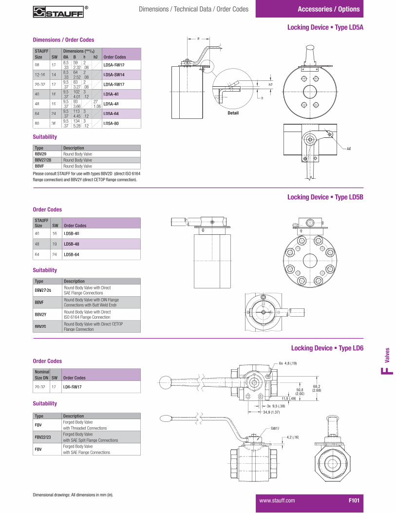
Valv
esF
����������� F101
Accessories / OptionsDimensions / Technical Data / Order Codes
Locking Device � Type LD5A
STAUFF Dimensions (mm/in)Size SW ØA B h h2 Order Codes
08 12 8,5 59 2 LD5A-SW12.33 2.32 .08
12-16 14 8,5 64 2 LD5A-SW14.33 2.52 .08
20-32 17 9,5 83 2 LD5A-SW17.37 3.27 .08
40 16 9,5 102 3 LD5A-40.37 4.01 .12
48 19 9,5 93 27 LD5A-48.37 3.66 1.06
64 24 9,5 113 3 LD5A-64.37 4.45 .12
80 36 9,5 134 3 LD5A-80.37 5.28 .12
Locking Device � Type LD6
Type Description
FBVForged Body Valvewith Threaded Connections
FBV22/23Forged Body Valvewith SAE Split Flange Connections
FBVForged Body Valvewith SAE Flange Connections
Suitability
%�&�'�+.2
3%�4�'+�352
36��4�7�'�392
11,9 (�%4)
50,8(&�<<)
68,2'&�.92
.6��%�9�'�+42
SW17
Order Codes
Dimensions / Order Codes
AØAØ
h
h2
B
iDetail
NominalSize DN SW Order Codes
20-32 17 LD6-SW17
Type DescriptionBBV29 Round Body ValveBBV27/28 Round Body ValveBBVF Round Body Valve
Suitability
@ ��������� ���EG�HH���������������#���IIJ&K��'������M�$�.+.%N�������������2�����IIJ&P�'�������QE$@�N�������������2�
Locking Device � Type LD5B
Order Codes
Suitability
STAUFFSize SW Order Codes
40 16 LD5B-40
48 19 LD5B-48
64 24 LD5B-64
Type DescriptionRound Body Valve with ��� ��SAE Flange Connections
BBVF Round Body Valve with ����������Connections with Butt Weld Ends
BBV2Y �����������!��"��#�$���� ��ISO 6164 Flange Connection
BBV2D �����������!��"��#�$���� ��CETOP Flange Connection
K��������� �����������G ������������������'��2�

F102� �����������
Accessories / Options Technical Data / Order Codes
Double-Acting Pneumatic Actuators � Type EDASingle-Acting Pneumatic Actuators � Type ESA
EDA - 200
STAUFF Size 08STAUFF Sizes 02 to 0602 to 06
STAUFF Size 12STAUFF Size 16
STAUFF Size 32
STAUFF Size 24
STAUFF Size 20
EDA - 100
EDA - 65
EDA - 45
EDA - 25
EDA - 12
Torq
ue in
ft/lb
(1 ft
·lb =
1,3
5 N·
m)
Pressure in PSI(1 PSI = 14,5 bar)
Selection Chart for Double-Acting Pneumatic Actuators EDA���E���\���I� �J� �����������������������]����� �$� ������������KM^�7+7&%�E+�����E&
Most STAUFF ball valves can be factory-mounted to compact,efficient double-acting or single-acting pneumatic actuators���!���������#������������ ���#���������## ���������
The actuators feature simple, robust construction and are �����! ������## ������������������� ����`�����������
Please note: The minimum air supply for STAUFF actuators������� ��7�7�!���q�9<�@�M��E��������������������4<w��#���q�close applications only and should not be used for valve ������ ����
Select the size of your pneumatic actuator from theselection charts on the right and consult STAUFF forfurther information.
Selection Chart for Single-Acting Pneumatic Actuators ESA���E���\���I� �J� �����������������������]����� �$� ������������KM^�7+7&%�E+�����E&
Pressure in PSI(1 PSI = 14,5 bar)
STAUFF Size 08
STAUFF Size 12STAUFF Size 16
STAUFF Size 32
STAUFF Size 24
STAUFF Size 20
Torq
ue in
ft/lb
(1 ft
·lb =
1,3
5 N·
m)
ESA - 350
STAUFF Sizes 02 to 0602 to 06
ESA - 600
ESA - 200
ESA - 100
ESA - 40ESA - 25
ESA - 25Q �������������#������������ ������ �������� �������� ������������������ ������� �! ���������� ���!�������������������� ������ ���������x���
@ ��������� ���EG�HH����������������������
Limit Switches
Warning: The selection charts are only valid for the following ball valve types supplied by STAUFF:������������������� �������������������������������

Valv
esF
����������� F103
Accessories / OptionsDimensions / Technical Data
Ball Valves with Detent
STAUFF Nominal Dimensions (mm/in)Size Size DN SW K H R g t
02 412 175 45 20 6 7.47 6.89 1.77 .79 .24 .28
04 612 175 45 20 6 7.47 6.89 1.77 .79 .24 .28
05 814 200 45 29 6 4.55 7.87 1.77 1.14 .24 .16
06 1014 200 45 29 6 4.55 7.87 1.77 1.14 .24 .16
08 1314 200 45 29 6 4.55 7.87 1.77 1.14 .24 .16
10 1617 200 45 29 6 4.67 7.87 1.77 1.14 .24 .16
12 2017 240 45 28 6 4.67 9.45 1.77 1.10 .24 .16
16 2517 240 45 28 6 4.67 9.45 1.77 1.10 .24 .16
DimensionsMulti-Way Ball Valves (Types LBV / TBV / XBV)
Ball Valves with Assembly Holes
Ball Valves with Assembly Threads
STAUFF Nominal Dimensions (mm/in)Size Size DN SW a g t
02 49 31 4,3 4,5.35 1.22 .17 .18
04 69 31 4,3 4,5.35 1.22 .17 .18
05 89 31 4,3 4,5.35 1.22 .17 .18
06 109 32 4,3 4.35 1.26 .17 .16
08 139 32 4,3 4.35 1.26 .17 .16
10 1612 32 5,2 6.47 1.26 .20 .24
12 2014 44 6,2 6.55 1.73 2.44 .24
16 2514 44 6,3 6.55 1.73 .25 .24
DimensionsBlock Body Ball Valves (Types BBV / CBV / CBVS)
STAUFF Nominal Dimensions (mm/in) ISOSize Size DN SW LK g t1 t2 w 5211
02 4 9 36 M5 6 7,5, 30° * F03 *.35 1.42 .24 .30
04 6 9 36 M5 6 7,5, 30° * F03 *.35 1.42 .24 .30
05 8 9 36 M5 6 7,5, 30° * F03 *.35 1.42 .24 .30
06 10 9 36 M5 7 9 45° F03.35 1.42 .28 .35
08 13 9 36 M5 6 8 45° F03.35 1.42 .24 .31
10 16 12 42 M5 8 10 45° F04.47 1.65 .31 .39
12 20 14 50 M6 10 14 45° F05.55 1.97 .39 .55
16 25 14 50 M6 10 12 45° F05.55 1.97 .39 .47
20 32 17 50 M6 8 12 45° F05.67 1.97 .31 .47
24 40 17 50 M6 8 12 45° F05.67 1.97 .31 .47
32 50 17 50 M6 8 12 45° F05.67 1.97 .31 .47
DimensionsBlock Body Ball Valves (Types BBV / HBV / CBV / CBVS up to STAUFF Size 16)Forged Body Ball Valves (Types FBV from STAUFF Size 20 on)
* 30° is not corresponding to ISO 5211@ ��������� ���EG�HH����������������������
@ ��������� ���EG�HH����������������������
@ ��������� ���EG�HH����������������������

F104� �����������
Accessories / Options
Alternative Porting Patterns
LLu
Lu
L
T
L
T
T
L
T
LL
TL LI TL TI
Symbol Porting Pattern
58-BBV35
57-BBVS35
50-CBV
51-CBV
55-CBVS *
56-CBVS *
01
02
03
04
06
08
09
BBV35
BBVS358 CBV
CBVS
Not Allowed
Three-Way LBV/ TBV with Stop of End Position
Type
90°
180°
90°
90°
90°
90°
90°
90°
45°
45° 90° 90° 90°
Operating Angle
negative
negative
negative
negative
negative
negative
positive positive negative negative negative negative negative
Overlap
~�@���������� ���#����! ������� �#������]����!���#���������������#�������� �#������]����!�
~�@���������� ���#����! ������� �#������]����!���#���������������#�������� �#������]����!�
Stop of End Position
Technical Data

Valv
esF
����������� F105
Accessories / Options
Alternative Porting Patterns
T
X X XI XI LI XT TL XL XL L
Symbol Porting Pattern
Four-Way TBV / XBV with Stop of End Position
Type
90° 90°
45°
45°
90°
90°
90°
90°
90°
90° 180°
Operating Angle
positive negative ����� ���� position negative negative negative negative negative negative negative
negative positive
Overlap
Stop of End Position
13 16 15 16 17 18 19 21 22 23 24
Technical Data

F106� �����������
Special Application Valves
Highest-Pressure Ball Valves
These valves are being utilised:
800 bar / 1200 PSI ball valve combination foralternating pressure demands from 6 bar / 87 PSI upto 800 bar / 12000 PSI working in a hose testing plant.
The STAUFF range of valves have stood the test of time for ultra high pressure applications up to 800 bar / ���������
��������������������������������������������������������������������������������������������!"##��$��%�������������������&�������������������������������������������$�������������������������������$���������������������������Additionally the sealing system is protected against erosion���������������$��������
The ball valves are utilised in Test Stations, Steel Works, '������������'���������������
Ball valve for a test bed: The customers demandwas to apply high pressure and great volume to the specimen in a short time.
��������� �������������������������
For High pressure water blasting� ��������������������������(�����������������&���� �������������� pipe cleaning � surface treatment like chamfering, descaling, varnish
removal
For process and industrial technology� ')��*��&�������� hydroforming� test bed technology� ������+�����������������
High temperature ball valves with heatingelements for polymer production.
High-Temperature Ball Valves
In order to provide the many advantages of ball valves in hightemperature applications, STAUFF has developed the FBVT���������������������
���������������������������������������$�-�������$������������������������������������$$�������������������$�����������������������������������$���������
"$���������$����������.�1��2'�3�.4���2#��������������$�����������������������������������������������������������$��������������$���������������������������$����������������
For temperatures up to +500 °C / +932 °F STAUFF has������$������$�������������������������������������;��$��������������������������������$�������(���������corrosion under high temperatures, the leak rate of these��������������������$���������������������������

Valv
esF
����������� F107
Special Application Valves
Ball Valves for Gas Applications
���������������������������� ������������������������������!
� General gas supply systems,� Filling plants, � compressor stations,� gas stations, � �������������$����
Ball valves with pneumatic actuator in gas stations.
�������������������������������<���$�����;��������=>3�?3<'�
The ATEX Directive for hazardous location EX II 2G c��������$�������������������������������
The materials for body, ball and seals are dependanton the gas and application in consideration of the ����������
Ball Valve DN PN (bar) Approved Material Combination forType Combination Hazardous Location EXII 2G c (ATEX)
BBV 6 - 25 16 Carbon or Stainless Steel / NBR (Buna-N®) 11aA / 44aA
FBV 32 - 50 16 Carbon or Stainless Steel / NBR (Buna-N®) 21 aA / 44aA
BBV 6 - 25 100 Carbon or Stainless Steel / NBR (Buna-N®) 11 aA / 44aA
BBV 6 - 25 500 / 315* 24HA / 44HA 21aA / 44aA
FBV 32 - 50 315* 24HA / 44HA 24aA / 44aA
@�����������$������&������������������$������������������������
#��������������������$����;H����������J������������(�������������?3�K���K�������������������(������K���������������and ball valves for manifold mounting and cartridge ball ��������������������������
���������������������������������������������;�H�?�?������4(����������$��L �����L�(�M���������������������%���;�H�<H� ���NK?� (�'����%������������������<���$�����;��������=>3�?3<'�
�������-���������������$�������������O���������-��������device up to a leakage rate of 10*=������&��3���
��!"##�����������������������������������������������$���������������������������&��������������������������������-�$���� � �Only if the most important parameters like pressure, medium, temperature, medium concentration and operation cycles are-����������������������������������������������������������������������������������������������
<&�$������������������������������������������������-tions the chemical resistance and further directives are to be �����������#���#��������-���&����(���������(������(����������������������������������������������
����������$$�������Y�#���J����������������������$�����ZO��[�*�$���������������������������������������������������H!'<���������M\) >4�
Double block and bleed valve for sampling.
Gas stations:#�������$��$������������������������J�������������������������������������������������M������$����������������������������������������$����������������������������������!��������������������������)�4� ��������������������
Ball valves for analysis techniques and Sampling]������������������������������^����������-����������������^�������������$���������������������!_#�\<�*�������������������������������������������������������������!K_���Z����������������������������[�������������������$$������������������$�������������������
�������������� ����������������� ������"���STAUFF-3-way-selector ball valves for 250 bar / 3600 PSI and +200°C / +392 °F.
����������������������������J��������������������?K���K��������������������������������������%���������������������������;�����������&�������`jK����������������������������������������������������������������-K�����������$$��������

F108� �����������
Special Application Valves
Ball Valves for Paints and Lacquers
Ball valve application in airless spraying device.
]��������������$������������������������������������against the varying viscosities and dye particles in����J�����
The sealing material is the determining factor to guarantee����$�����������������������������������������$�����������������������$�����������������������������������������$�����������������������������$�����������������������������������������$�������(��������������������������������
Ball Valves for Isocyanates
To maintain or repair the valve, it is necessary that the return and non-return lines in colour spraying plants can be blocked��
Due to the opening of the bypass ball valve, an un-pressurised�������������������������������
The locking or opening of the bypass line is carried out��������(������������������$�������������$��������
����������������������������������������$������������$������������������������������������������������������������������������������(�����������������������������$����������-$�����
)��������������������������������$���������������J���������q��������������������������$��������������������because standard plastic seats can be damaged by �����������$���������
With these sealing system from STAUFF a ball valve$���������&���������������
These valves are being used in the foaming systems����$��������]�������������������������������������������devices and temperature sensors in order to keep the���$�����������������������������������������$�������
<���$$�������������������������������������!"##�������������������$����������������������������������
���������������������������������������������������������������$���������������#����������������������������������and also a reduction of repair and maintenance time, a metal��������������������������
�����$��%����������������������������������������������$$���������
The chemical resistance to the used solvent has to be tested�����������������������������
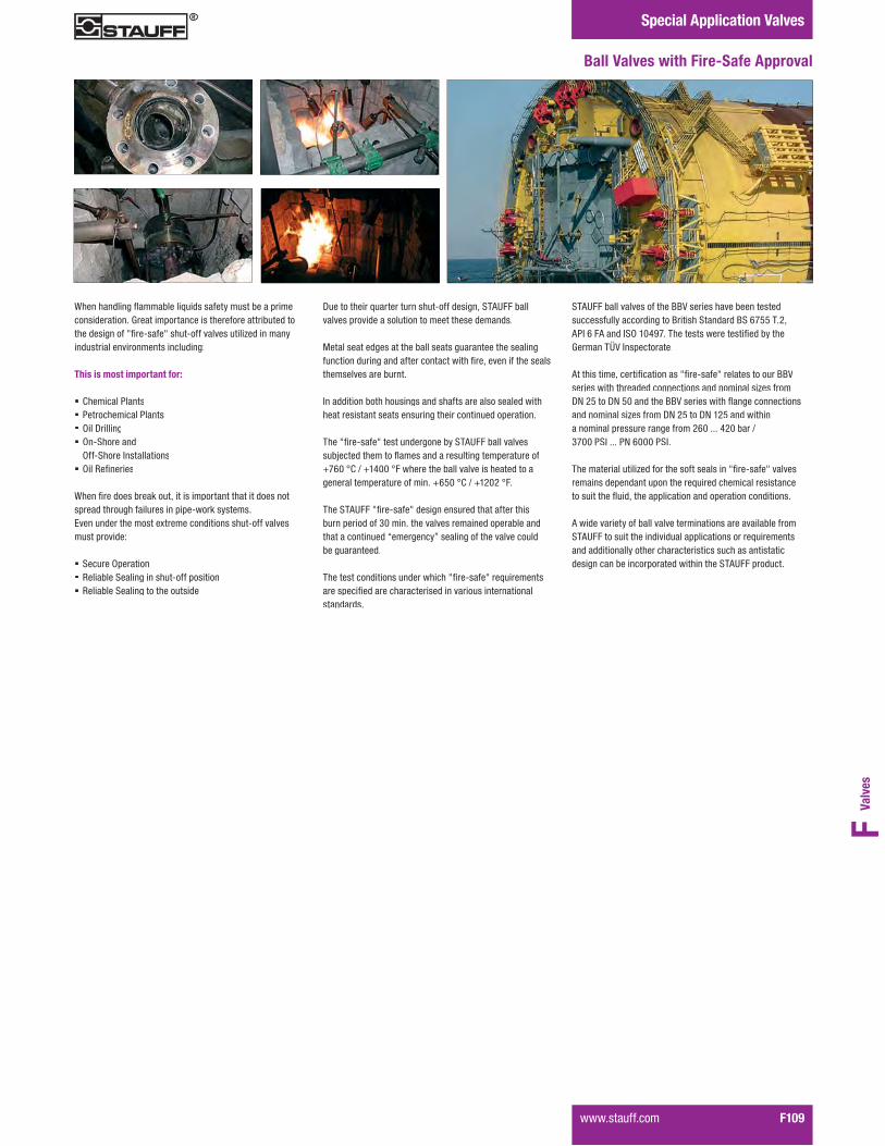
Valv
esF
����������� F109
Special Application Valves
STAUFF ball valves of the BBV series have been tested ���������������������]����������������]��1>44����(!���1�#!�������)� �N=>����������������������%���������L�������wj����$��������
!�����������(�����%���������^%��K���^����������������]]j����������������������������������������������x������;H��4����;H�4����������]]j�������������J�����������������������������x�������;H��4����;H� �4����������������������$�������������������1������N�������3�?>������������H�1��������
������������������x�����������������������^%��K���^������������������$��������$��������������������������������������������J���(������$$�������������$������������������
!������������������������������������������������������������!"##�������������������������$$������������������������and additionally other characteristics such as antistatic �����������������$��������������������!"##�$������
{�������������J��������������������������������$�������������������L�������$���������������������������������������������^%��K���^�����K��������������x�����������industrial environments including:
This is most important for:
� Chemical Plants� Petrochemical Plants� Oil Drilling� On-Shore and
Off-Shore Installations� )���\�%������
{����%������������-����(���������$������������������������$������������������������$�$�K���-����������<��������������������&��������������������K��������must provide:
� Secure Operation� Reliable Sealing in shut-off position� Reliable Sealing to the outside
Ball Valves with Fire-Safe Approval
;�����������������������������K��������(���!"##������������$����������������������������������������
Metal seat edges at the ball seats guarantee the sealing����������������������������������%��(���������������������������������������
�������������������������������������������������������������������������������������������������������$��������
����^%��K���^���������������������!"##���������������+�������������J������������������������$����������.>1��2'�3�. N���2#������������������������������������������������$���������������.14��2'�3�. ����2#�
������!"##�^%��K���^������������������������������������$��������?����������������������������$����������that a continued “emergency” sealing of the valve could��������������
������������������������������^%��K���^�������������������$��%������������������������������������������������������

F106� �����������
Special Application Valves
Highest-Pressure Ball Valves
These valves are being utilised:
800 bar / 1200 PSI ball valve combination foralternating pressure demands from 6 bar / 87 PSI upto 800 bar / 12000 PSI working in a hose testing plant.
The STAUFF range of valves have stood the test of time for ultra high pressure applications up to 800 bar / ���������
��������������������������������������������������������������������������������������������!"##��$��%�������������������&�������������������������������������������$�������������������������������$���������������������������Additionally the sealing system is protected against erosion���������������$��������
The ball valves are utilised in Test Stations, Steel Works, '������������'���������������
Ball valve for a test bed: The customers demandwas to apply high pressure and great volume to the specimen in a short time.
��������� �������������������������
For High pressure water blasting� ��������������������������(�����������������&���� �������������� pipe cleaning � surface treatment like chamfering, descaling, varnish
removal
For process and industrial technology� ')��*��&�������� hydroforming� test bed technology� ������+�����������������
High temperature ball valves with heatingelements for polymer production.
High-Temperature Ball Valves
In order to provide the many advantages of ball valves in hightemperature applications, STAUFF has developed the FBVT���������������������
���������������������������������������$�-�������$������������������������������������$$�������������������$�����������������������������������$���������
"$���������$����������.�1��2'�3�.4���2#��������������$�����������������������������������������������������������$��������������$���������������������������$����������������
For temperatures up to +500 °C / +932 °F STAUFF has������$������$�������������������������������������;��$��������������������������������$�������(���������corrosion under high temperatures, the leak rate of these��������������������$���������������������������

F110� �����������
Technical Appendix
���������� ���������
Nominal Pressure PN The nominal pressure indicates the pressure rate of a hydraulic component and � �� ������� ������������� ������ ������������ �������� �������������������������� ��� ���� �������������������
These nominal pressure values are internationally recognised and assist to appoint ���� ����� � ������ ��� ������������������������ �������������� �� �����������������������!������ �����"#!�$%$&����� ��#'(���&)����������������������������������*�����!��
���� ��� ��������������������������������������+� ������������������,%& -.�/�0) -����������� �������������������������� �����������������������
Maximum Working Pressure Pmax.
P���� ������������������+� ������������������� � ��� ���� ��������������+�������������������� ����� ������������� ����������������������+� ���������������� �������������������������� ����� ���
Burst Pressure PBurst
���������������������������������������������� �������%�1����������� ��� ������������PBurst 2 %�1 � �!
Nominal Diameter DN
���� ��� ����������������� ���������� ��� ������� ����������������� ������ �����������������������������������3�*������������4� ��������� ��� �������������������������������������������������������������������� �����5����������������������+������'�67�������������������"!%�/$%�������������� ������������������������ ��"!�%��� ����������������� ��"!�$%�
Leakage Rate
8��+������������������������������ ����������������9�"#!�:!��%%00����+���������6;!����������� ������������+�������� ������������� �����������������4����������<�
Standard Materials
Material Description Standard Temperature Range 1 ApplicationsFree Cutting Steel11SMn30(formerly 9SMn28K)
1.0715 /�����������(SAE 1213)
-20°C ... +120°C-4°F ... +248°F
General oil hydraulics without special requirements on the material
Low Alloy Steel S355J2G3(formerly St52-3)
1.0570 /����������
-40°C ... +120°C-40°F ... +248°F
General oil and water hydraulics as well as gas applications with special requirements to the yield stress
Stainless Steel X6CrNiMoTi17-12-2X5CrNiMo17-12-2X2CrNiMo17-13-2
������������1.4571 (AISI 316 Ti)1.4401 (AISI 316)1.4404 (AISI 316 L)
-200°C ... +200°C-328°F ... +392°F
Special applications in the chemical and power industries with specific requirements on the material and corrosion protection
���� ����� ���������� ������� ��� �� ���
Ball Seats
1 >� �����������������������9�6����� ������������� ����������������������������� ������������������������ ����� ���������+� �� ���� ��������� �2 ���������/�����������������������������������
Material Description Trade Name Temperature Range Applications
PolyacetalPOM
������Hostaform CUltraform
-30°C ... +100°C-86°F ... +212°F
High pressure and wear resistance, low water absorption, particularly suitable for hydraulic oils, other oils and water based hydraulic fluids
PolytetrafluorethylenePTFE
TeflonHostflonFluon
-200°C to +220°C 2
-328°F ... +428°F 2
Excellent chemical resistance to almost all fluids, no water absorption, low surface�������������������������������!�"��������������#�!�$���%�������&Higher characteristic compounds available.
Polyvinnylidenfluorid'*��
�:����KynarSolef
-40°C ... +120°C 2
-40°F ... +302°F 2
Mechanical properties like Teflon, but higher rigidity and lower thermal stability, resistantto ketones and esters at higher temperatures
PolyetheretherketonePEEK
ArlonVictrex
-40°C ... +250°C-40°F ... +482°F
Good chemical resistance to many mediums, suitable for steam, high temperatureresistance, high wearability
Cast ironGG25
0.60257�����; �
-40°C ... +250°C-40°F ... +482°F
Applications for abrasive fluids
Material description Trade Name Temperature Range Applications
AcrylonitrileButadiene Rubber NBR
Buna NPerbunanHycarChemigum
-30°C ... +100°C-86°F ... +212°F
Good technical properties, therefore especially suitable for oils and gaseous mediums
Fluor RubberFPM
VitonFuorelTecnoflon
-20°C ... +200°C-4°C ... +392°F
High chemical resistance to various mediums, in particular mineral oils, fuels and concentrated acids
Ethylene Propylene������<���$���=�����EPDM
Buna APNordel
-50°C ... +130°C-58°C ... 266°F
Good ageing stability, low wear, especially suitable for actylene, brake fluids, hot water, superheated steam, cooling gases, low-flammable liquids based upon Phosphoric acid
PolytetrafluorethylenePTFE
TeflonHostflonFluon
-200°C ... +220°C 2
-328°F ... +428°F 2
Excellent chemical resistance to almost all fluids, no water absorption, low surface �������������������������������!�"��������������#�!�$���%�������&Higher characteristic compounds available.
Stem and Adapter Sealing Materials
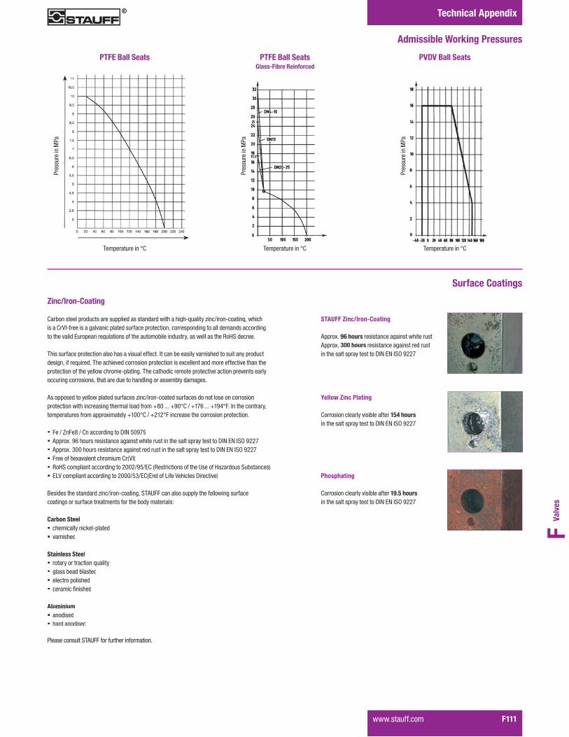
Valv
esF
����������� F111
Technical Appendix
Admissible Working Pressures
PTFE Ball Seats PTFE Ball Seats Glass-Fibre Reinforced
PVDV Ball Seats
Temperature in °C Temperature in °C Temperature in °C
Pres
sure
in M
Pa
Pres
sure
in M
Pa
Pres
sure
in M
Pa
Surface Coatings
Zinc/Iron-Coating .���� ���������������������������������� ����������������@A�������3� /��� @���� �*������is a CrVI-free is a galvanic plated surface protection, corresponding to all demands according�������������:������ ���������� �������������������� ������*����������������5�F'�������
������������������� ������������������������#��� �������������� ��������������� �������������� *�����A�������������������������� ��������� ���������� ��� ����������������� ������������� �������������������@����� ����������������������������������� ������ ������������� ��������� �*������������������� ��� ����������������������
6����������������������������������3� /��� @���������������� ��������� �������� ��������� ������� ����� �������������������,)&�����,G&-.�/�,�H0�����,�G1-���# ������ �����*��������������������������������,�&&-.�/�,%�%-��� ����������������� ��������� �
� Fe / ZnFe8 / Cn according to DIN 50979� 6�������G0�������������� ������ ��������������� ������������������������"#!�:!�#'(�G%%H� 6�������$&&�������������� ������ ������������� ������������������������"#!�:!�#'(�G%%H� ��������������� ����������.�;W#<� RoHS compliant according to 2002/95/EC (Restrictions of the Use of Hazardous Substances)� ELV compliant according to 2000/53/EC(End of Life Vehicles Directive)
k�������������� �����3� /��� @���� �*�'�67���� ����������������������� ��������coatings or surface treatments for the body materials:
Carbon Steel� chemically nickel-plated� varnished
Stainless Steel� ���������������� �A������� glass bead blasted� electro polished� ������� �����
Aluminium� anodised� hard anodised
�������� �����'�67�������������� ������� �
STAUFF Zinc/Iron-Coating
6�������96 hours ������� ������ �������������6�������300 hours resistance against red rustin the salt spray test to DIN EN ISO 9227
Yellow Zinc Plating
Corrosion clearly visible after 154 hoursin the salt spray test to DIN EN ISO 9227
Phosphating
Corrosion clearly visible after 19.5 hoursin the salt spray test to DIN EN ISO 9227

F112� �����������
Technical Appendix
Determination of the Nominal Diameter
Using a Nomogram
This nomogramm provides a guide for the determination������ ��� ������������;"!<��{�������� ������������������� ��4�������������������������� �9
'���� ��� ��9 &*������� &*)��/���;��������� �%1��/��<5���� ��� ��9 %*&������ 1*&��/���;�0��������%%��/��<����������� ���|�&�}��9 %*&������ 1*&��/���;�0��������%%��/��<����������� ���|�&�}��9 $*&������%*&��/���;�G������$�00��/��<
Example 1
W���������2�)��/���;%�11 ft/sec)����������~�2���&��/�� �;1&�7'>�}<
��������������� ���� +� �������������������� ������������������ ������������ ��� ������������"!�%&�� �����������������
Example 2
W���������2��*���/���;��0)�ft/sec)����������~�2�00��/�� �;�H�7'>�}<
��������������� ���� +� �������������������� ������������������ ������������ ��� ������������"!��0�� �����������������
Please note:
!�������� ������ ������������������������ �������������*��������� ��������*���������*������������������������� ����������� ��������������
.� �����'�67�������������� ������� �
Determination of the Nominal Diameter
Using a List of Nominal Flow Rates
����� �������4����������������� �������� ������������������ ���� �������� �������������������������������,��-.�/�,0&-��
Kv ���������
���� ��� ���4������������� ���v according to German ��� �����W"#/W":�%�H$�� �����������A�� �������������� ��������������������;��/�<���
���2�������/��1����'#�� ��$�����/��;'�<������������,������,$&-.�/�,1������,)0-.�
Cv ���������
The Cv ������;������������������ ��������� �7'6<����������������7'������ ����������4������������������������minute (US GPM) at
���2�������/��1����'#����,��-.�/�,0&-��
.� �����'�67�������������� ������� �
Nominal Size DN Kv Cv
(mm) (in) (m3/h) (US GPM)
15 1/2 19,4 22,6
20 3/4 45,6 53,0
25 1 71,5 83,1
32 1-1/4 105 122,1
40 1-1/2 170 197,7
50 2 275 319,8
65 2-1/2 507 589,5
80 3 905 1052,3
100 4 1414 1644,2
125 5 2362 2746,5
150 6 3694 4295,3
Example 2
Example 1

Valv
esF
����������� F113
Technical Appendix
Sealing Variations
Two-Way Ball Valves (Type LBV)
�����������������4���� �������
�������������������������� ��������������������Sealing is achieved by the ball being pushed against ������� ���������������������������������1 �����
Without pressure the sealing is guaranteed by the �������� ������������� ������� ���
�������������������� �� ������
The sealing element seals from the upsteam��������������� ���������� ������ ������������������ ����� ���#������������������������� ������� ���� ����������� ������������
Multi-Way Ball Valves
Three-Way Ball Valves (Type CBV)
���������������������������%�������� ����4���� �������
If the shut-off port is pressurised and p1 is higher than p2, then the ball is being forced against the opposite ����� ������� ��
6����������� �����������������������+� ��
X3:1
p1 p2pp1 p2
Three-Way Ball Valves (Type CBVS)
p1 p2 p1 p2p
Gap
X3:13
The selector ball valve has 2 front side sealing������� ����4���� �������
p1 > p2
Due to the forming of the ring surface „f1“ and the ���������;��@�%<�������������� ������� ������������������ ������������� ��� ��A�� ������������� ���� ������������������4���� ������������������ ���������right sealing surface - the ball valve remains�������
Pressure inlet possible from all ports!Must be operated without pressure!
p1 < p2
Due to the ring surface „f2“ and the pressure ;�%@��<���������������� ������� ����������������������� ������������� ��� ��A�� ������������� ������������������4���� ������������������ ���������������� ��������@��������������������� ���������
Pressure inlet possible from all ports!Must be operated without pressure!
pGap
X3:13
p1 p2
Special Protected SeatsFor compressible and abrasive media special protected�������������������
"��� ������������������� � ������������������*���� �����plastic seats are located unprotected in the critical cross ����� ��������
"��� ��������������� ��� �����������+� ��������������������������� ������������������� �� ��������� �������������4������������������������ �������������
#�������� ��� �������*��������������� �*������������ ����+�� ������������� � ������� �������������������
k������������������� ������������ �A��+��������� ����������
For this application, STAUFF has designed a sealing������ ������������ ��������� ��� ����������� ����������������������������� ��+��������������4��������� �����������������������������������������������
������� ���� �������������� ��������������������� ��������� ��������������������������������� ���������������������� ��������������������������
�������� � @������������������ �� � ��� �����������������������������������
A further increase of the lifetime is possible by using����������� ������� ���
The ring is made of special material andprotects the seats against erosion.

F114� �����������
Technical Appendix
Torque Figures
Torque / Operation Pressure Curves
Operating torquefor ball valves with
POM seats
BBVCBV
BBV22/23
Operating torquefor ball valves with
����� �� �"# ���
FBVFBV22/23
Operating torquefor ball valves with
POM seats
LBVTBVXBV
0 100 200 300 400 500 600 700 800
iPressure in bar
Ti
NTo
rque
in N
· m
0 50 100 150 200 250 300 350 400
iPressure in bar
iTo
rque
in N
· m
0 50 100 150 200 250 300 350 400
iPressure in bar
iTo
rque
in N
· m
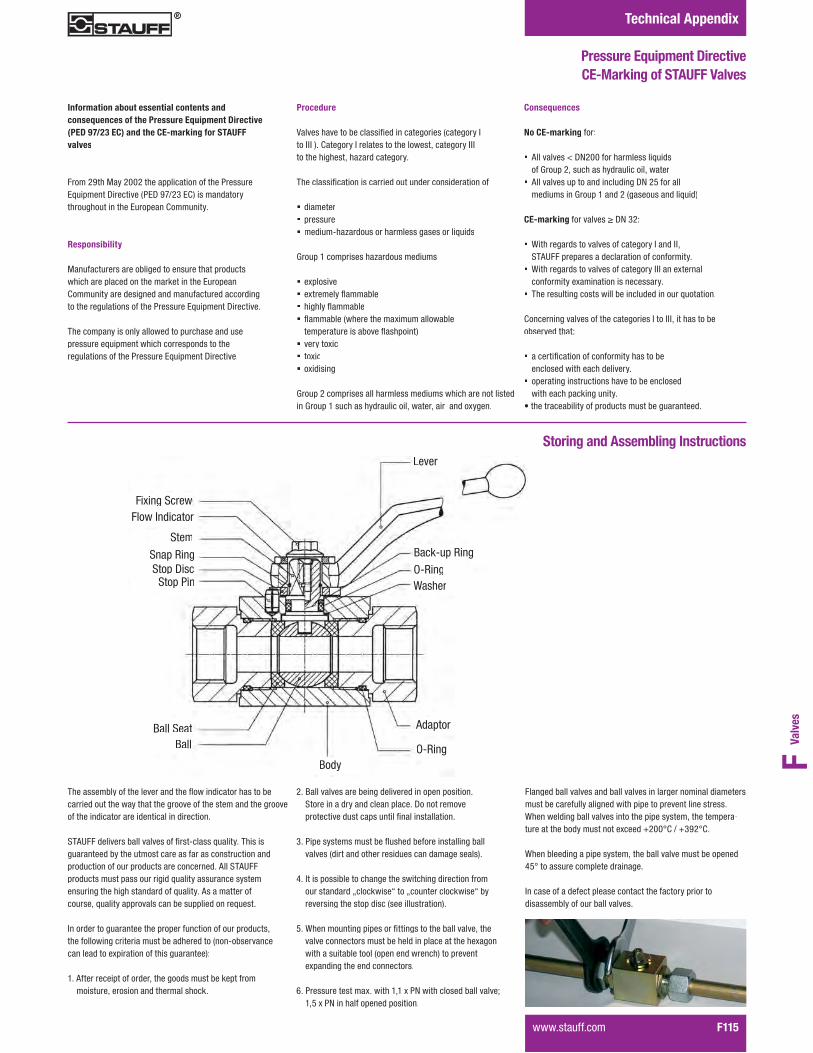
Valv
esF
Technical Appendix
Pressure Equipment Directive CE-Marking of STAUFF Valves
Information about essential contents andconsequences of the Pressure Equipment Directive(PED 97/23 EC) and the CE-marking for STAUFF valves
From 29th May 2002 the application of the Pressure:A����� ��"��������;�:"�GH/%$�:.<������ ������������������� �����:������ �.���� ����
Responsibility
Manufacturers are obliged to ensure that products ���������������� ��������+���� �����:������ �Community are designed and manufactured according���������������� �����������������:A����� ��"���������
�������� ������ ����������������������� ���������������A����� �������������� ������������������� �����������������:A����� ��"��������
Procedure
W��������������������������� �����������;��������#���###�<��.��������#����������������������*���������###��������������*���3������������
�������������� ���������������� ����� ��������� ��
� diameter� pressure� ������@��3������������������������������A����
Group 1 comprises hazardous mediums
� ���������� ����������4�������� �������4�������� 4��������;���������������������������
���������������������4������ �<� ���������� ����� ������� �
>�����%���������������������������������������� ���������� �>��������������������������*������*������� ������� �
Consequences
No CE-marking for:
� 6������������"!%&&���������������A����of Group 2, s������������������*������
� All valves up to and including DN 25 for all��������� �>�������� ��%�;��������� ����A���<
CE-marking ������������"!�$%9
� With regards to valves of category I and II,'�67����������������������� ���� �������
� {��������������������������������###�� ������ ��� ������������ ���� ���� ��������
� ����������� ���������������� ������� �����A������� �
Concerning valves of the categories I to III, it has to beobserved that:
� ����������� ���� ������������������ ���������� �������������
� operating instructions have to be enclosed�����������+� ��� ����
����������������������������������������� �����
Storing and Assembling Instructions
���� ��'��������# ������
Stem
Snap RingStop Disc
Stop Pin
Ball SeatBall
BodyO-Ring
AAdaptor
WasherO-RingBack-up Ring
Lever
�������������������������� ������4���� ��������������������������������������������������������������� �������������������� �������������� ������ �������� �
'�67������������������������������@�����A���������������guaranteed by the utmost care as far as construction and �������� �������������������� �� ����6���'�67�������������������������������A������������� ��������� ���� �������������� �������A��������6������������������*�A������������������ �������������� ���A�����
In order to guarantee the proper function of our products, ���������� �����������������������������; � @������� �� ������������������ ������������� ���<9
���6������������������*�������������������+������������������*������� �� �������������+��
%��k������������������ ������������� ���� �������� ������'������ �������� ����� �������"�� ���������������������������������� ����� ���� ��������� �
$�����������������������4������������� ������ ������������������;������ ������������������ �������������<��
1��#������������������� ������������� ��������� ��������������� ��������+������������ ������+������������������� ���������������;��������������� <�
���{�� ���� �� ��������������� ��������������������*��������������� �������������������� ������������������� �������������������������;��� �� ����� �<��������� �������������� �� ������� ��� ������
0���������������������������*�����!����������������������������*�����!�� �������� ���������� �
Flanged ball valves and ball valves in larger nominal diameters�������������������� ��������������������� ���� ����������{�� ������ ��������������� ������������������*������������-���������������������� ���������,%&&-.�/�,$G%-.��
When bleeding a pipe system, the ball valve must be opened1�-����������������������� �����
In case of a defect please contact the factory prior to �������������������������������
����������� F115

Technical Appendix
F116� �����������
Seal Kit for Two/Three-Way Block Body Valves
Seal Kits
������ ���� ������������������% ���� (@�� ��������������$ ���� k�+@����� ��������������1� 1 %����% � k���������������������� %���� (@�� ������������
STAUFFSize Order Codes
04 BBVS/K047101M
06 BBVS/K067101M
08 BBVS/K087101M
12 BBVS/K124501M
16 BBVS/K164501M
Order Codes for Seal Kit Ordering Guide for Block Body Ball Valves endingin …01M (Delrin/Viton seat/seal combination)
Threaded and SAE Flange ConnectionsTypes BBV and CBV
Assembly Instructions Notice: The change of seals should only be undertaken���������� ���� ��A�����������������{�������� ��that seals are only replaced at STAUFF or by one of our �������3���������������*�������������A����������������� ��������� �����
�� Dismantlement9�5�������� ������� � ��4������������������������������ ������������ �����F68��(�:!�������� �� ����� ��������(�:!�������� ��7 ������������������;� ��@��+����<��5������������; ����������� ��������� ����������������� <������������ �� ����������������� �������������� �����.8(':"�������� ��"���������������������������� ������ �������������������������5����������(@�� ������������������������������������;����������������������<��5������������������������;� ���������������<��������������
%� Preparation: Prior to replacing seals ensure that all ���� � ���������� �� ��������� ��� ���� ���� �6������������� ���� ��(@�� ��������������������������������������������������� �� ����������������������������������������������������W����� ��
$��Pre-Assembly9�}�� ��������������������;�����<�� �������������������5������(@�� ���;����%,�<�;��� ����������������<�� ������������� ��� ���������������Ensure that O-rings are not damaged on keen edges or�����������*�;������������� ���������������������������������A����������� ����������������*������ ������������� ������� �� ���������<�
k�+@����� ���;����$<���������������������������(@�� ��;����%<*������� �������������������������: �������������back-up ring is located in the groove to avoid any dam-���������������� �����������������������
1� Assembly: Reassemble the stem to the body bypressing and turning at the same time, and then align the �������������������������������� �������
��� ��������������� �� ��� ����������� ����������G&-�;.8(':"�������� <�� ��������������� ��������������� �������������������� ���������� ������������� ���� ����������� �����������������������>� ����������������������� ������������� ����+����������������(@�� ������� ��������������
������ ���������������������A�������� ������� ������������9
DN4-6: 48 NmDN10: 90 NmDN13: 110 NmDN16: 110 NmDN20: 220 NmDN25: 250 Nm
������������������������������A������ ���� �������������������������� ���� ����������������� ���������������� ����� ���6���������� ���������������
���Test: Test to ensure that the valve can be opened and��������������{�������� ���������������������������������������&*0�}���� ��� �������+� �����������������������������A���*�������*�����!�� �������������� �������������#����������������������� ��� ����������������������������������� ��������������������������������������������������������������������������������� ���������������������������*���������������������� ���������� ������� �������������� �� ��@������� �������� ��
'���������������� �����(�:!�������� ���
STAUFFSize Order Codes
24 BBVS/K242701M
32 BBVS/K322701M
48 BBVS/K482701M
60 BBVS/K602701M
Direct Mount Flange ConnectionsTypes BBV27/29 and BBVF
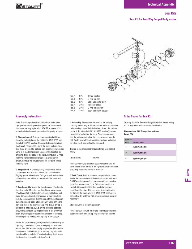
Valv
esF
Technical Appendix
����������� F117
Seal Kit for Two-Way Forged Body Valves
Seal Kits
������ ���� ������������������% ���� (@�� ��������������$ ���� k�+@����� ��������������1 %���� k���������������������� %���� (@�� �����������������0 %���� k�+@����� ������������
STAUFFSize Order Codes
20 FBVS/K204501M
24 FBVS/K244501M
32 FBVS/K324501M
Order Codes for Seal Kit (����� ��>�����������@{����������k����k����W������� �� ��in …01M (Delrin/Viton seat/seal combination)
Threaded and SAE Flange ConnectionsTypes FBV
Assembly Instructions Note: The change of seals should only be undertaken���������� ���� ��A�����������������{�������� ��that seals are only replaced at STAUFF or by one of our �������3������������������������ ��������A����������������
���Dismantlement9�5�������� ������� � ��4����������������������������� ������������ �����F68��(�:!�� ���� ��������(�:!�������� ��7 �������������������;� ��@��+����<��5������������; ��������������� ��������� ����������������� <������������ �� ����������������� �������������� �.8(':"�������� ��"���������������������������� ������ �������������������������5����������(@�� ������������������������������������;���������������������<��5������������������������;� ���������������<�������������
%� Preparation: Prior to replacing seals ensure that all ���� � ���������� �� ��������� ��� ���� ���� �'�������������������������� ��(@�� �������������������������������������������������� �� ������������������������W����� ��
$��Pre-Assembly9�}�� ��������������������;�����<�� ������������������}�� ���@�� ��;����%<�� ����+@����� �;����$<���������� ��������������� ������������������ �avoid damages through sharp edges or overstretching;������������� ���������������������������������A����by using suitable tools, alternatively by using a thin and�������<��}�� �������������+@����� ��;����$<�� �����������������@�� ��;����%<*������� �������������������������Ensure that the back-up ring is located in the groove to ������� ��������������������� �����������������������}�� �� ��������� ��������+@����� �����������������
}�� ��������+@����� ��;����0<���������� ��������������by using a rounded tool (no sharp edges), but ensure to �������������������� ��� ��� �����������������6����������������;��������$&����0&����<�������+@����� ������� ������������� �������� ����3��������������+@����� ����������������������� ����� ������(@�� ��;�����<�
1��Assembly: Reassemble the stem to the body by pressing and turning at the same time, and then align the������������ ���������������������������# ��������������� �� ����������� ����������G&-�;.8(':"�������� <�� ��������������� ��������������� �������������������� ��������into the body ensuring that the concave areas face the ������>� ����������������������� ������������� ����+����������������(@�� ������� ��������������
������ ���������������������A�������� ������� ������������9
DN32-DN50: 800Nm
�����������������������������A������ ���� ������������������������� ���� ����������������� ����������������� ����� ���6���������� ���������������
���Test: Check that the valve can be opened and closed��������{�������� ���������������������������������������&*0�}���� ��� �������+� ������������������������������A����;����������<*�������*�����!�� �������������� �������������6�����������������4������������������������� ���������������������� �������������������� ����������������������*��������� �F68��(�:!�������� ��8����������������� �������������� �� ��@������������ �*�� ��������
'���������������� �����(�:!�������� �
Please consult STAUFF for details on the recommended �������� ������������+@����� ������������ ���������

Technical Appendix
F118� �����������
Seal Kit for Multi-Way Block Body Valves
Seal Kits
Assembly Instructions Notice: The change of seals should only be undertaken���������� ���� ��A�����������������{�������� ��that seals are only replaced at STAUFF or by one of our�������3���������������*�������������A����������������� ��������� �����
��Dismantlement: In order to release the remaining��������*���������������������� �������� ��
"���������������������� ����;�����0<��7 ������������������;������<�� ��@��+������5������������;����H<��7 ��������;����1<������������������������������������� ��@��+������5��������� �� ��;�����1<�� ������� ��������;����$<��5����������(@�� ���� ����+@����� ����������� �� ����������������� �������������������������;�����������������������������������<�
%� Preparation: Prior to replacing seals ensure that all ���� � ���������� �� ��������� ��� ���� ���� ��>��������������������W����� ����������� ������� ���� �(@�� ��������������������������������������������������� �� �������������������
$�����@6�������9��6��������(@�� ���;�����<�� ����+@����� ���;�����%<�� ���������������������� �� *���+@���� ����������������������������� ��
}�� ����������(@�� ���� ��������;����G<����������;������<������� �����������������;���"!%&�����%�<��
Attention: Ensure that O-rings are not damaged on keen ���������������������*�;������������������� ���������������������������������A����������� ����������������*������ �������������� ������� �� ���������<�
6��"!1����"!�09��������� �� ��������;�����$<�� ���������������������������������� ���;����H<*����������DN20 and DN25: place seal element in the sleeve (no ��������� �� �����������<*�������������������������������������������(@�� ���������� ������� ��;����)<�� ������������� ������� ��;����H<*�;���������"!%&�� ��"!%�������� ���������<�� ����������������� ���������
���@���������(@�� ��;����0<�� �����������;����1<��; ����9�� ����������������� �������� ����������<�
1��Assembly: First assemble the bearing shells (bushing) ;2����$<�� ����������;�����<�� �����;����1<������������������������������������������������� ����� ����������� be used as chamfer for the O-ring (and back-up ring) of ������� �� �Notice: Ensure that the back-up rings lie close to each other in the groove so that during the assembly process������������� �������������� �����������
6������������������ ����������� �� �;������A��������������������������<�����������;����1<���������� �� ����� � �������������������
"!1����"!�09������(@�� ��������;����0<�� ����������
������������ �� �;����������������<�� ���������*�� ���������������������������������������*���������������� ��������� �������� ���������������������A���;���������<�
>� ���������� ��������@�������������������� ������������ ��� ��������������(@�� ����� ������������������ ������������������������������������A���
5���������������;�����&<����������������A��������������������������������� �� ��� �����������*������������ ����� ��;������<��6�������������� ����;�����0<���������������;��������������� �������<�
�� Test: Test to ensure that the valve can be opened � ����������������{�������� �������������������������������0���������� ��� �������+� ������������������������������A���*�������*�����!��#�����������������testing ensure the after the test procedure has been ���������������������������������������������������
����������������������������� �����������������������*��������������������� ���������� �������� �������������� ��@������� �������� ��
Store the valve in the „OPEN” or “CLOSED” position,������� ��������� �
����$ %���� k���� ������ %����� (@�� �������� �� ������% %���� ��+@����� �����
O-ring on trunnion����H 1���� k��������������$ 1���� }�� �� ������
for ball seat����) 1���� (@�� ������������������G 1���� (@�� ����������������0� 0 ����� � (@�� ��������
Tightening Torques of Adaptors and Endcaps
Nominal SizeAdapterTightening Torque in N · m Thread
EndcapTightening Torque in N · m Thread
���>�; 40 M18 x 1,5 120 ... 140 }$)����*�������� 70 M22 x 1,5 140 ... 160 }1�����*��������; 110 M30 x 1,5 320 ... 350 }0&����*����� 180 M38 x 1,5 550 ... 600 })&���%��� ����?��>�& 250 M45 x 1,5 650 ... 700 }G%���$
STAUFFSize Order Codes
04 XBVS/K047101M
06 XBVS/K067101M
08 XBVS/K085801M
12 XBVS/K124501M
16 XBVS/K164501M
20 XBVS/K164501M
24 XBVS/K164501M
Order Codes for Seal Kit Ordering Guide for Block Body Ball Valves endingin …01M (Delrin/Viton seat/seal combination)
Threaded ConnectionsTypes LBV / TBV / XBV
Valv
esF
����������� F119
Notes