Ventilator/Respirator - Fundamentals and...
77
Ventilator/Respirator Hardware and Software Design Specification Rev. 0, 11/2011
Transcript of Ventilator/Respirator - Fundamentals and...

Ventilator/Respirator Hardware andSoftware Design Specification
Rev. 0, 11/2011

Ventilator/Respirator Hardware and Software Design Specification , Rev. 0, 11/2011
2 Freescale Semiconductor, Inc.

Contents
Section Number Title Page
Chapter 1Introduction
1.1 Introduction.......................................................................................................................................................................7
Chapter 2Features
2.1 Features.............................................................................................................................................................................9
Chapter 3System Background
3.1 System Background..........................................................................................................................................................11
3.2 System sensors..................................................................................................................................................................12
3.3 Spirometer.........................................................................................................................................................................12
3.4 Flow measurement............................................................................................................................................................13
3.5 Alarm system....................................................................................................................................................................15
3.6 Human machine interface.................................................................................................................................................15
3.7 Air and oxygen blender and mix control..........................................................................................................................18
3.8 Breathing controller..........................................................................................................................................................19
Chapter 4Hardware Design
4.1 System definition..............................................................................................................................................................21
4.1.1 Microcontroller .....................................................................................................................................................23
4.1.2 Pressure sensors.....................................................................................................................................................25
4.1.3 Power supply..........................................................................................................................................................27
4.1.4 Analog To Digital Converter (ADC) ....................................................................................................................29
4.1.5 Keyboard Interruptions (KBI)................................................................................................................................29
4.1.6 Universal Serial Bus (USB)...................................................................................................................................30
4.1.7 General Purpose Input Outputs (GPIO).................................................................................................................30
4.2 Bill Of Materials (BOM)..................................................................................................................................................30
Ventilator/Respirator Hardware and Software Design Specification , Rev. 0, 11/2011
Freescale Semiconductor, Inc. 3

Section Number Title Page
4.3 Schematics........................................................................................................................................................................35
4.3.1 MCU block.............................................................................................................................................................35
4.3.2 Power supply..........................................................................................................................................................36
4.3.3 BDM and Reset......................................................................................................................................................37
4.3.4 USB and Clock.......................................................................................................................................................37
4.3.5 Actuators switching................................................................................................................................................38
4.3.6 Alarms....................................................................................................................................................................39
4.3.7 Sensors...................................................................................................................................................................39
4.3.8 Human Machine Inteface (HMI)............................................................................................................................40
4.4 Layout...............................................................................................................................................................................41
4.4.1 Layout design.........................................................................................................................................................41
4.4.2 Physical PCB..........................................................................................................................................................44
4.4.3 Ventilator Suitcase.................................................................................................................................................46
Chapter 5Software Design
5.1 Introduction.......................................................................................................................................................................51
5.2 Software system description.............................................................................................................................................51
5.3 Software architecture........................................................................................................................................................53
5.3.1 Hardware Abstraction Layer (HAL)......................................................................................................................55
5.3.1.1 General Purpose Op Amp (GPAMP).......................................................................................................55
5.3.1.1.1 GPAMP.c................................................................................................................................56
5.3.1.1.2 GPAMP.h................................................................................................................................56
5.3.1.2 General Purpose Inputs Outputs (GPIO).................................................................................................56
5.3.1.2.1 GPIO.c....................................................................................................................................56
5.3.1.2.2 GPIO.h....................................................................................................................................56
5.3.1.3 Key Board Interruptions (KBI)................................................................................................................56
5.3.1.3.1 KBI.c.......................................................................................................................................56
5.3.1.3.2 KBI.h.......................................................................................................................................57
Ventilator/Respirator Hardware and Software Design Specification , Rev. 0, 11/2011
4 Freescale Semiconductor, Inc.

Section Number Title Page
5.3.1.4 Timer/ Pulse-Width Modulator (TPM)....................................................................................................57
5.3.1.4.1 TPM.c.....................................................................................................................................57
5.3.1.4.2 TPM.h.....................................................................................................................................57
5.3.1.5 Multipurpose clock generator (MCG)......................................................................................................57
5.3.1.5.1 MCG.c.....................................................................................................................................57
5.3.1.5.2 MCG.h....................................................................................................................................58
5.3.1.6 Analog to Digital Converter (ADC).........................................................................................................58
5.3.1.6.1 ADC.c.....................................................................................................................................58
5.3.1.6.2 ADC.h.....................................................................................................................................58
5.3.1.7 Digital to Analog Converter (DAC).........................................................................................................58
5.3.1.7.1 DAC.c.....................................................................................................................................58
5.3.1.7.2 DAC.h.....................................................................................................................................58
5.3.2 Hardware Independent Layer (HIL).......................................................................................................................59
5.3.2.1 Sensors.....................................................................................................................................................59
5.3.2.1.1 Sensors.c.................................................................................................................................59
5.3.2.1.2 Sensors.h.................................................................................................................................60
5.3.2.2 LCD..........................................................................................................................................................60
5.3.2.2.1 LCD.c......................................................................................................................................60
5.3.2.2.2 LCD.h.....................................................................................................................................61
5.3.3 Services..................................................................................................................................................................61
5.3.3.1 General Services......................................................................................................................................61
5.3.3.2 Services.c.................................................................................................................................................61
5.3.3.3 Services.h.................................................................................................................................................62
5.3.4 Measurement and conversion services...................................................................................................................62
5.3.4.1 Metering _Algorithm .c............................................................................................................................62
5.3.4.2 Metering _Algorithm .h...........................................................................................................................62
5.3.5 Application.............................................................................................................................................................62
5.3.5.1 Main.c......................................................................................................................................................62
5.3.5.2 Config.h....................................................................................................................................................65
Ventilator/Respirator Hardware and Software Design Specification , Rev. 0, 11/2011
Freescale Semiconductor, Inc. 5

Section Number Title Page
Chapter 6Parameters Configuration
6.1 Parameters configuration..................................................................................................................................................67
Chapter 7Troubleshooting
7.1 Troubleshooting ...............................................................................................................................................................69
7.1.1 Main issues.............................................................................................................................................................69
7.1.2 Main board connections.........................................................................................................................................72
Chapter 8Conclusion
8.1 Conclusions and References.............................................................................................................................................75
Ventilator/Respirator Hardware and Software Design Specification , Rev. 0, 11/2011
6 Freescale Semiconductor, Inc.
Chapter 1Introduction
1.1 IntroductionThe ventilator (also known as a respirator) is a pneumatic and electronics systemdesigned to monitor, assist, or control pulmonary ventilation, and respirationintermittently or continuously. It can also be used to control human body oxygen levels,for example during surgery where blood loss can result in hypoxia, or lack of sufficientoxygen in the patient´s body; it is best to have less human interaction. Mechanicalventilation is designed to maintain an adequate exchange of gases, even throughdiminished breathing rates and reduced myocardial use. However, it can also be used toprovide adequate lung expansion, the correct combination of anesthetic sedation formuscle relaxing, and stabilize the thoracic wall.
The respirator is made of a compressed air reservoir, air and oxygen supplies, a set ofvalves and tubes, and a disposable or reusable patient circuit. The air reservoir ispneumatically compressed several times a minute to deliver room-air or in most cases anair/oxygen mixture. The lungs elasticity allows releasing the overpressure, this is calledpassive exhalation, and the exhaled air is released usually through a one-way valve withinthe patient circuit. The oxygen content of the inspired gas can be set from 21 percent(ambient air) to 100 percent (pure oxygen).
This reference design simulates basic human lung behavior. It is easy to test differentpulmonary therapies without connecting a lung to the device. The objective of thisdevelopment platform is to showcase Freescale product capability while developing aventilator or respirator. it represents a complex application where accurate measurement,correct instrumentation, power manager, and signal integrity are a critical factor forcorrect operation of a machine which a human life may depend on.
Ventilator/Respirator Hardware and Software Design Specification , Rev. 0, 11/2011
Freescale Semiconductor, Inc. 7

Introduction
Ventilator/Respirator Hardware and Software Design Specification , Rev. 0, 11/2011
8 Freescale Semiconductor, Inc.
Chapter 2Features
2.1 FeaturesMain components:
• MCF51MM256 32-bit Coldfire Freescale MCU with analog modules (DAC, internalOp Amps) ideal for medical and instrumentation appliances.
• MPXV5050GP (0 to 50 KPa single pressure) and MPX7002DP (-2 to +2 KPadifferential pressure) compensated Freescale sensors.
• MHP1-M4H (14 lts/min, at 5 V, 1 W, 250 Hz, 2/2, M3) electro valves.• 12 V at 10 A i300 Good Year automotive Air compressor 15 lts/min.• 500 mA transistors power stage (TIP31C) for valves and buzzer, and a 15 A relay
(JSM1A-12V-5) for the air compressor.• Aluminum air mixture chamber (30 PSI max) 4 outputs (M3).• Multi-gain analog temperature sensor 0-3 V output voltage.• 20 X 4 character 5 V LCD display (C-51847NFJ-SLW-ADN).• Alarm buzzer MAG 2.0 KHZ 3 V• Tactile buttons and LED indicators.• USB device connector.• 1 L anaesthetic bag to simulate human lungs• Medical Venturi pipe to measure the flow from the pressure difference
Functions:• Moves air in and out of the air container to assist, monitor, or control ventilation• Control air mixture percentage by pressure.• Human interface to monitor and control main parameters as respiration frequency,
pressure, measure units and control mode.• Lungs basic behavior simulation (air container bag).• Three control modes ( Pressure, Frequency, and Assisted)• Control of one air compressor, and supportable PID functions for four valves
Resources:
This system uses the following resources from the MCF51MM256:
Ventilator/Respirator Hardware and Software Design Specification , Rev. 0, 11/2011
Freescale Semiconductor, Inc. 9

• 11 I/O ports• Five 16-bit ADC ports• Three TPM ports• Four KBI ports• Two Internal Op Amps• Eight MHz bus clocks with FLL• 1 Internal 12-bit DAC• Device USB
Features:• Accurate measurement• Simple and effective control• Low cost electronic system• Analogue amplification internally connected with adjustable reference• USB connectivity• Configurable gain amplification and amplificatory configurations• Capability to probe a lot of different control algorithms and configurations
Features
Ventilator/Respirator Hardware and Software Design Specification , Rev. 0, 11/2011
10 Freescale Semiconductor, Inc.
Chapter 3System Background
3.1 System BackgroundA ventilator is a machine designed to mechanically move air in and out of the lungs tointermittently or continuously assist or control pulmonary ventilation. This device isprimarily used in intensive therapy to help improve the patients breathing by regulatingthe flow of gas in the lungs. The most common indicators of the ventilation are theabsolute volume and changes of volume of the gas space in the lungs achieved during afew breathing maneuvers. The ventilator is constantly monitored and adjusted to maintainappropriate arterial pH and PaO2.
This system requires a set of sensors for pressure, volume, and flow. The informationfrom the sensors modulates the operations in the MCU. This MCU receives informationfrom the airways, lungs, and chest wall through the sensors, and decides how theventilator pumps.
The pneumatic system has two air supplies that can be oxygen and air, and can comefrom a pressurized tank or compressor. Both sources are regulated by two input valves tocontrol mixture composition, which comes from an air tank where the mixture is kept atcertain pressure limits. If the mixture composition is correct and is in the right pressurerange, the system sends this air to the patient to control breathing. For this system has aninput and output valves connected to lungs simulator to control pressure in lungs and therespiratory frequency to maintain patient safety. Figure 3-1 shows the pneumatic systemfor this ventilator.
Ventilator/Respirator Hardware and Software Design Specification , Rev. 0, 11/2011
Freescale Semiconductor, Inc. 11

Figure 3-1. Pneumatic system diagram
3.2 System sensorsThe signal that shows lung volume is a differential signal, but this is not the signalmeasured directly from the lungs. To get this signal, it is necessary to transduce thepressure to voltage. This is done by using a pneumotachometer that contains a pressuresensor.
Freescale provides a variety of sensors that use integrated circuits for signal conditioning.This is an advantage because external components are not necessary. However, it isnecessary to check the sensor and ADC resolution. If the ADC resolution is greater thanthe sensor resolution, amplifying the signal is recommended. Some sensors providedifferential outputs to pass the signal through an instrument amplifier, when necessary.The sensor that fits volume measurement is a differential pressure sensor that accepts twosources of pressure simultaneously. The output is proportional to the difference of thetwo sources. It is important to mention that the normal pipeline gas source of a hospital is50 PSI. This is a measurement that can be taken by Freescale pressure sensors.
3.3 SpirometerSpirometers measure static pulmonary volumes, except the functional residual capacity(FRC) and total pulmonary capacity (TPC). The measurement is executed after amaximum inspiration that requires the patient to expel the entire volume of air that he orshe can. The results are interpreted and compared with the expected values for age,height, sex, and race of the patient. Normal values can fall between 80 to 120 percent ofthe expected volume; this is due to variations among normal individuals.
Lung volume measurements include:• Tidal volume (TV)—Amount of gas inspired or expired with each breath (500 ml)
System sensors
Ventilator/Respirator Hardware and Software Design Specification , Rev. 0, 11/2011
12 Freescale Semiconductor, Inc.
• Inspiratory reserve volume (IRV)—Maximum amount of additional air that can beinspired at the end of a normal inspiration (2500 ml)
• Expiratory reserve volume (ERV)—Maximum volume of additional air that can beexpired at the end of a normal expiration (1500 ml)
• Residual volume (RV)—The volume of air remaining in the lungs after a maximumexpiration (1500 ml). These measurements can be used in the following equations toexpress lung capacities:
• Eqn. 1—Total lung capacity (TLC)• TLC=RV+IRV+TV+ERV (6000 ml)
• Eqn. 2—Vital capacity (VC)• VC=IRV+TV+ERV=TLC-RV (4500 ml)
• Eqn. 3—Functional residual capacity (FRC)• FRC=RV+ERV (3000 ml)
• Eqn.4—Inspiratory capacity (IC)• IC=TV+IRV (3000 ml)
3.4 Flow measurementThe Venturi effect is used to measure flow. This is the reduction in fluid pressure thatresults when a fluid flows through a constricted section of a pipe. This effect is called ajet effect because the velocity of the substance increases on the way from the widesection to the narrow section. The pressure also increases over a smaller surface area; thesame force applied to a smaller area equals a higher pressure in that area. According tofluid dynamics, a fluid's velocity must increase as it passes through a constriction tosatisfy the conservation of mass, while its pressure must decrease to conserve energy.Equation 5 refers to the Venturi effect
Eqn. 5 Venturi effect :
Where is the density of the fluid, v1 is the (slower) fluid velocity where the pipe is wider,v2 is the (faster) fluid velocity where the pipe is narrower (as seen in the figure). Thisassumes the flowing fluid (or other substance) is not significantly compressible, eventhough the pressure varies, the density is assumed to remain approximately constant.
Chapter 3 System Background
Ventilator/Respirator Hardware and Software Design Specification , Rev. 0, 11/2011
Freescale Semiconductor, Inc. 13

Figure 3-2. Venturi effect graphically demonstration
Figure 3-3 shows Venturi pipes used in industrial and in scientific laboratories formeasuring liquid flow. This case system uses a reusable medical Venture pipe, called aD-Lite sensor.
Figure 3-3. Venturi real pipe application for a D-lite sensor
Figure 3-3 shows the sensor with three sampling ports. During inspiration the gas flowsfrom the ventilator to the patient, A measures the total pressure, B measures the staticpressure. The difference between the two gives a dynamic pressure, which is proportionalto the velocity of gas flow. During expiration the process is reversed. C measures CO2,O2, and anesthetic gas concentration.
A Venturi can be used to measure the volumetric flow rate Q.
Since:
Eqn.6
Then:
Eqn. 7
Flow measurement
Ventilator/Respirator Hardware and Software Design Specification , Rev. 0, 11/2011
14 Freescale Semiconductor, Inc.

Divide as follows:
Eqn.8
Finally, the pneumatic system has a constant value relating pressure with flow, you canmeasure directly the differential pressure from the venture, square root it and multiply itfor your system constant to obtain the instant volumetric flow.
NOTESince differential pressure can be measured, you canexperimentally obtain the constant factor of the system by usinga flow source.
3.5 Alarm systemAn important part of this application is the alarm that indicates different patientparameters such as exhaled volume or airway pressure. The ventilation system must beable to detect whether a breath has been taken. The MCU measures changes in aspiratoryflow and pressure by using sensors. If no inspiration is detected within a certain period oftime, the monitor sounds an alarm. The conditions programmed depend on each system.PWM cycles can be programmed to sound alarms. Sometimes, the ventilation systemuses different alarms for different situations.
3.6 Human machine interfaceFor the user to have control the system needs an interface with a turn On/Off function,configure, monitor parameters and modes. The system has 20 x 4 characters LCD displaythat displays the parameters and the four buttons to change them. Figure 3-4 shows thephysical interface for the suitcase.
Chapter 3 System Background
Ventilator/Respirator Hardware and Software Design Specification , Rev. 0, 11/2011
Freescale Semiconductor, Inc. 15
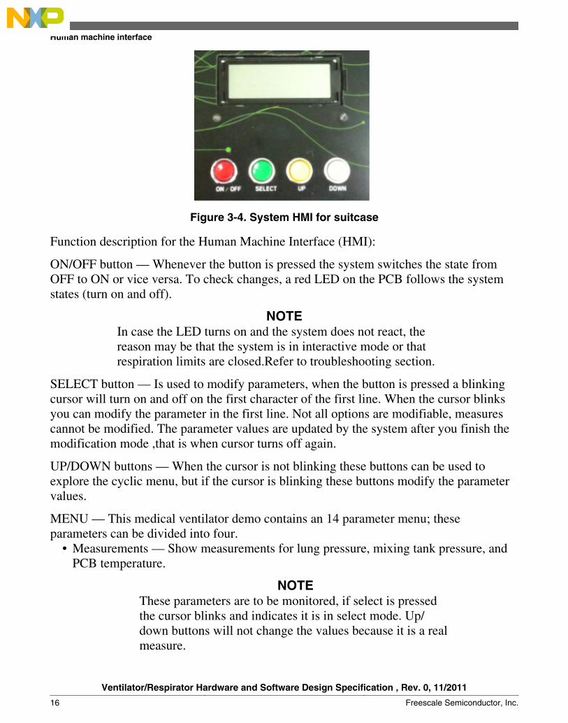
Figure 3-4. System HMI for suitcase
Function description for the Human Machine Interface (HMI):
ON/OFF button — Whenever the button is pressed the system switches the state fromOFF to ON or vice versa. To check changes, a red LED on the PCB follows the systemstates (turn on and off).
NOTEIn case the LED turns on and the system does not react, thereason may be that the system is in interactive mode or thatrespiration limits are closed.Refer to troubleshooting section.
SELECT button — Is used to modify parameters, when the button is pressed a blinkingcursor will turn on and off on the first character of the first line. When the cursor blinksyou can modify the parameter in the first line. Not all options are modifiable, measurescannot be modified. The parameter values are updated by the system after you finish themodification mode ,that is when cursor turns off again.
UP/DOWN buttons — When the cursor is not blinking these buttons can be used toexplore the cyclic menu, but if the cursor is blinking these buttons modify the parametervalues.
MENU — This medical ventilator demo contains an 14 parameter menu; theseparameters can be divided into four.
• Measurements — Show measurements for lung pressure, mixing tank pressure, andPCB temperature.
NOTEThese parameters are to be monitored, if select is pressedthe cursor blinks and indicates it is in select mode. Up/down buttons will not change the values because it is a realmeasure.
Human machine interface
Ventilator/Respirator Hardware and Software Design Specification , Rev. 0, 11/2011
16 Freescale Semiconductor, Inc.
• Limits and setpoints — Values for limits and setpoints for all the controllablevariables, these values have minimum and maximum possible values and are notcyclic.
• Measure units —These modifiable parameters are reflected after each measure anddenotes which units are used. Conversions are included and are valid for pressure,and temperature. It also is a cyclic menu.
• Mode of function — This parameter cyclically changes the operational mode of thesystem, there are three control modes.
• pressure• assisted• frequency
The 14 parameters shown in the menu are:• LUNGS_PRESSURE — Pressure measured from the simulating lungs bag• TANK_PRESSURE — Pressure retained in the air mixing chamber, this value
affects the velocity to fill lungs• OPERATION_MODE — Modifies the control mode for the system.• TEMPERATURE — Measures the typical highest PCB temperature (near the
voltage regulators), this compensates errors in the pressure measurement.• OXYGEN_PERCENTAGE — Shows and modifies oxygen percentage from the
air mixture.• TANK_LOW_PRESSURE — Modifies the tank low limit pressure for all
modes.• TANK_HIGH_PRESSURE — Modifies the tank high limit pressure for all
modes.• ALARM_TIME — Sets the alarm time for tank low level pressure, this
demonstrates tank air control.• LUNGS_LOW_PRESSURE— Modifies the lungs low limit pressure for the
pressure control mode.• LUNGS_HIGH_PRESSURE — Modifies the lungs high limit pressure for the
pressure control mode.• INSPIRATION_PERCENTAGE — Modifies the percentage of inspiration in a
whole breathing cycle for the frequency mode.• RESPIRATION_TIMES — Shows and modifies breaths per minute for the
frequency mode.• PREASSURE_UNITS — Converts units to PSI, Pascal, H20 cm, Hg mm, and
mbar• TEMPERATURE_UNITS — Choose between Celsius and Fahrenheit.
Chapter 3 System Background
Ventilator/Respirator Hardware and Software Design Specification , Rev. 0, 11/2011
Freescale Semiconductor, Inc. 17

3.7 Air and oxygen blender and mix controlThe air and oxygen blender provides a precise oxygen concentration by mixing air andoxygen. The concentration can be adjusted to any value from controlled air to 100percent oxygen. Internally, a proportioning valve mixes the incoming air and oxygen asthe oxygen percentage dial is adjusted. A variation in line pressure, flow, or pressurerequirements for any attached device will not affect the oxygen concentration.
The preparation of an air and oxygen blender generally consists of attaching a 50 PSI airand oxygen source to the device. After the source gases are attached, inlet pressures maybe checked on some blenders by checking the pressure-attached pressure gauge. After theinlet gases are attached and the air and oxygen blender is well secured to a stand or wallmount, it is ready for use.
The MCU uses a PWM to control the blender electro valves through a motor controldesign. Earlier ventilator designs relied on mechanical blenders to provide premixed gasto a single flow control valve. With the availability of high-quality flow sensors andprocessing capabilities, accurate mixing becomes possible by using separate flow valvesfor air and oxygen. Because air already contains about 21 percent oxygen, the total flowcontrol command between the oxygen and air valve is divided ratio metrically. Forextreme mix settings, the valve that supplies the minor flow at low total flowrequirements may fall below the resolution limits that either flow delivery ormeasurement can provide. An accurate delivered mix depends on accurate flow delivery,but if accurate and reliable oxygen sensors are used, improved mix accuracy may bepossible by feeding back a measured concentration for mix correction. Then, if thepatient needs more pressure, the MCU activates the compressor.
This mixture comes into an air tank, where mixture percentages are controlled bypressure with the following formula:
Eqn. 9
Where P1 is the initial gas pressure, P2 is the pressure that defines the A% (mixpercentage) inside the container, P3 is the final desired and mixed pressure.
The cycle process to control and prepare correct proportions for the mixture are asfollows:
Air and oxygen blender and mix control
Ventilator/Respirator Hardware and Software Design Specification , Rev. 0, 11/2011
18 Freescale Semiconductor, Inc.
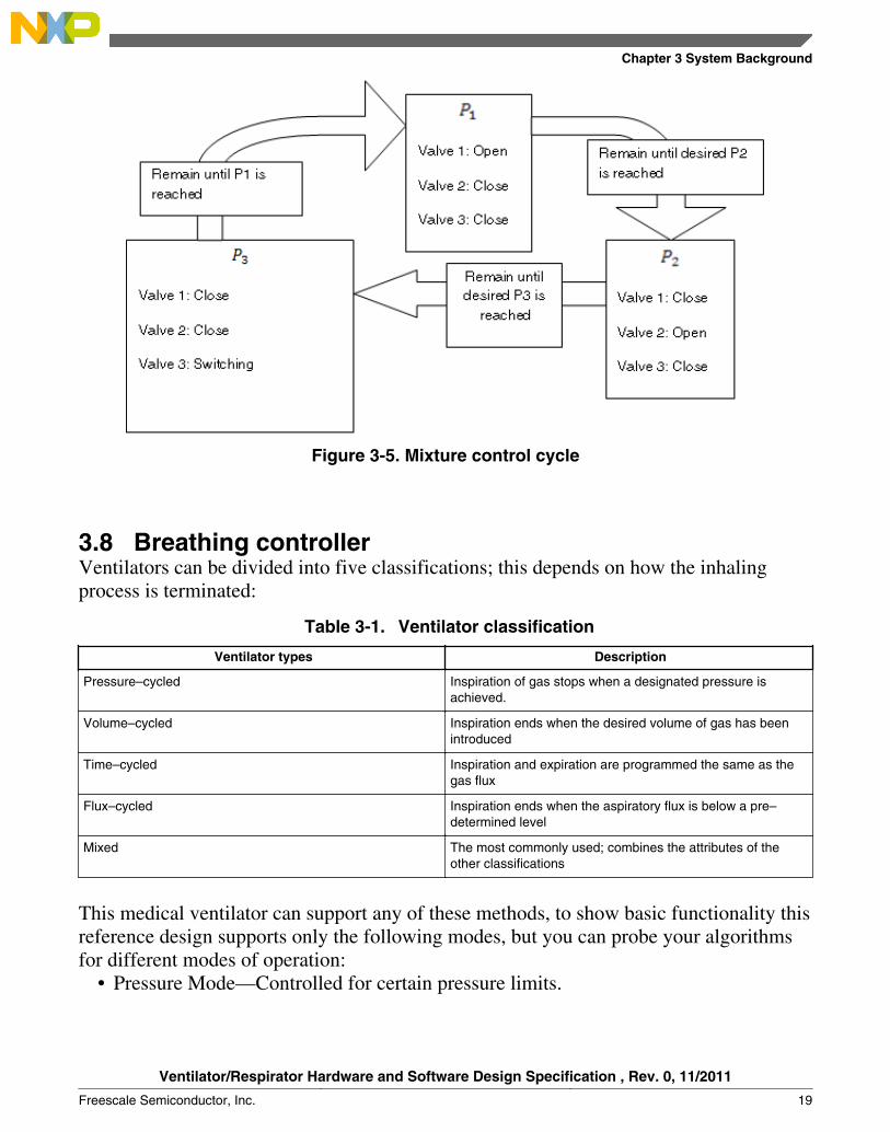
Figure 3-5. Mixture control cycle
3.8 Breathing controllerVentilators can be divided into five classifications; this depends on how the inhalingprocess is terminated:
Table 3-1. Ventilator classification
Ventilator types Description
Pressure–cycled Inspiration of gas stops when a designated pressure isachieved.
Volume–cycled Inspiration ends when the desired volume of gas has beenintroduced
Time–cycled Inspiration and expiration are programmed the same as thegas flux
Flux–cycled Inspiration ends when the aspiratory flux is below a pre–determined level
Mixed The most commonly used; combines the attributes of theother classifications
This medical ventilator can support any of these methods, to show basic functionality thisreference design supports only the following modes, but you can probe your algorithmsfor different modes of operation:
• Pressure Mode—Controlled for certain pressure limits.
Chapter 3 System Background
Ventilator/Respirator Hardware and Software Design Specification , Rev. 0, 11/2011
Freescale Semiconductor, Inc. 19

• Time–Mode—Respiration and expiration are executed to a certain frequency.• Assisted—Inspiration starts after a small effort executed by the lung simulator and
finishes only one cycle.
Breathing controller
Ventilator/Respirator Hardware and Software Design Specification , Rev. 0, 11/2011
20 Freescale Semiconductor, Inc.
Chapter 4Hardware Design
4.1 System definitionAn electronics system for a medical respirator can be complex because of the variety ofcomponents and functions that must be accurate.
It must have the following modules:
Power supply—This PCB must power the microcontroller, sensors, display and switchfour 200 mA valve, and a 12 A air compressor at different voltages. The requirements ofthe power supply are 12 A to 12 V (air compressor), 2 A to 5 V (four valves, bright LED,display and differential pressure sensors), and 500 mA to 3.3 V (MCU, buzzer, pressure,and temperature sensors). These modes are on the same PCB. A multi layer PCB will bea requirement. The planes stack selection is an important design action to avoid electricalnoise issues.
Communications (USB)—System requires a channel for connectivity with othercontrolling or monitoring devices to exchange data and provide complete control, forexample, anesthetic controllers. USB is a communication channel commonly used formedical devices. This system supports the Freescale’s Medical USB stack with a personalhealthcare device class (PHDC) that currently supports human interface device (HID),mass storage device (MSD), communications device class (CDC), audio class and PHDCUSB.org standard classes. The PHDC enables the software to allow USB connectivitywithin medical devices by complying with medical industry standards, such as theContinua Health Alliance. Medical ventilators are not supported by PHDC. CDC is agood option for sharing data from these devices.
Signals treatment and measuring from sensors—Reliable measurement is a critical factorfor this application. Signal treatment and decoupling are important factors to consider.The system must avoid electrical noise using capacitors and inductors for decoupling.This version does not use external analog treatment, it uses internal op amps to amplifysmall signals like differential pressure between the simulated lung and ambient without apumping system. Amplification can be easily modified with software and made
Ventilator/Respirator Hardware and Software Design Specification , Rev. 0, 11/2011
Freescale Semiconductor, Inc. 21

internally. For signals with natural offset (Freescale DP sensors), the referencemodification can be an important factor to amplify the signal without cutting it. In thiscase the Freescale MM microcontroller can be set with a software internal connection ofop amp inputs to a Digital to Analog Converter (DAC), changing the reference voltagewithout having to cut the signal..
Human Interface—This system is able to support some operational modes with differentparameter values. It is important to have a user interface for a personalized display oreven to explore therapies, events, or for teaching sessions. There is a 20 x 4 characterLCD that displays the main parameters and four buttons to explore the 14 option menu.As part of the user interface the system has LED’s for alarming, debugging, and a buzzerfor alarm events, and therefore the system provides enough information to the user.
Actuators controlling—System requires controlling several electromechanical actuatorsthat demand high current consumption and generates electrical noise to the system byEMI. The system requires a good electrical design to avoid noise generation and deviceprotection like optical switch and snubbers for switching. It is also critical to support andprovide enough current. The system uses Darllington transistors, optoislolators, andrelays to provide correct power management.
Figure 4-1 is the medical ventilator block diagram.
System definition
Ventilator/Respirator Hardware and Software Design Specification , Rev. 0, 11/2011
22 Freescale Semiconductor, Inc.

Figure 4-1. Electronic system block diagram
4.1.1 Microcontroller
One of the more critical modules for this application is signal treatment and measuring,this is because the respirator acts according to the data acquired. If this data is notreliable, the ventilator may do incorrect operations that can risk the patient’s health. It isimportant to select the appropriate MCU and sensors for instrumentation applications.Freescale offers reliable MCUs for medical instrumentation. Two examples are theMC9S08MM (8-bit MCU) and the MCF51MM (32-bit MCU). For this reference designthe MCU chosen was the MCF51MM256.
The MCF51MM256 provides ultra-low-power operation, USB connectivity, graphicdisplay support, and unparalleled measurement accuracy in a single 32-bitmicrocontroller. This allows device designers to create more fully featured products at alower cost.
Chapter 4 Hardware Design
Ventilator/Respirator Hardware and Software Design Specification , Rev. 0, 11/2011
Freescale Semiconductor, Inc. 23

The MCF51MM256 is ideal for medical applications or any other application requiring asignificant amount of precision analog such as instrumentation and industrial control.
The MCF51MM256 is part of the Freescale Flexis™ microcontroller series. This is asummary of the MCF51MM256 features.
• Up to 50.33 MHz ColdFire V1 core speed and 25 MHz bus speed• 256 K flash• 32 K SRAM• Two ultra-low-power stop modes• Time of the Day (TOD)• Two flexible operational amplifiers (OPAMP)• Two trans-impedance amplifiers (TRIAMP)• Multi-purpose clock generator (MCG)• Dual-role full-speed USB On-The-Go (OTG) controller and transceiver• Two serial communications interfaces (SCI)• Two serial peripheral interfaces (SPI)• Analog comparators• 16-bit Analog-to-Digital converter (ADC)• 12-bit Digital-to-Analog converter (DAC)• Mini-FlexBus• Analog comparator with selectable interrupt (PRACMP)• I2C interface• Programmable delay block (PDB)• Carrier modulation timer (CMT)• Two timer modules (TPM)• Voltage Reference Output (VREFO)• Up to 68 GPIOs and 16 rapid GPIOs
System definition
Ventilator/Respirator Hardware and Software Design Specification , Rev. 0, 11/2011
24 Freescale Semiconductor, Inc.

Figure 4-2. MCF51MM Block diagram
4.1.2 Pressure sensors
To measure accurately the control system, it is important to have the correct sensors. Thefollowing pressure sensors are used:
MPXv5050GP—0 to 50 kPa integrated silicon pressure sensor, temperaturecompensated, and calibrated
Key features:• 2.5 % maximum error over 0° to +85°C• Ideally suited for microprocessor or microcontroller-based systems• Temperature compensated over -40°C to +125°C• One analog output voltage (0 - 3.3 V), CASE 1369-01.
Figure 4-3 shows voltage versus the pressure graph.
Chapter 4 Hardware Design
Ventilator/Respirator Hardware and Software Design Specification , Rev. 0, 11/2011
Freescale Semiconductor, Inc. 25
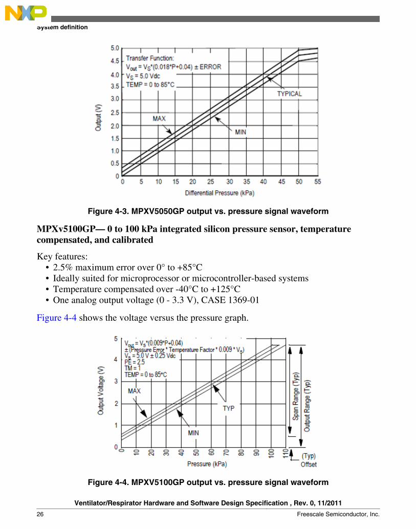
Figure 4-3. MPXV5050GP output vs. pressure signal waveform
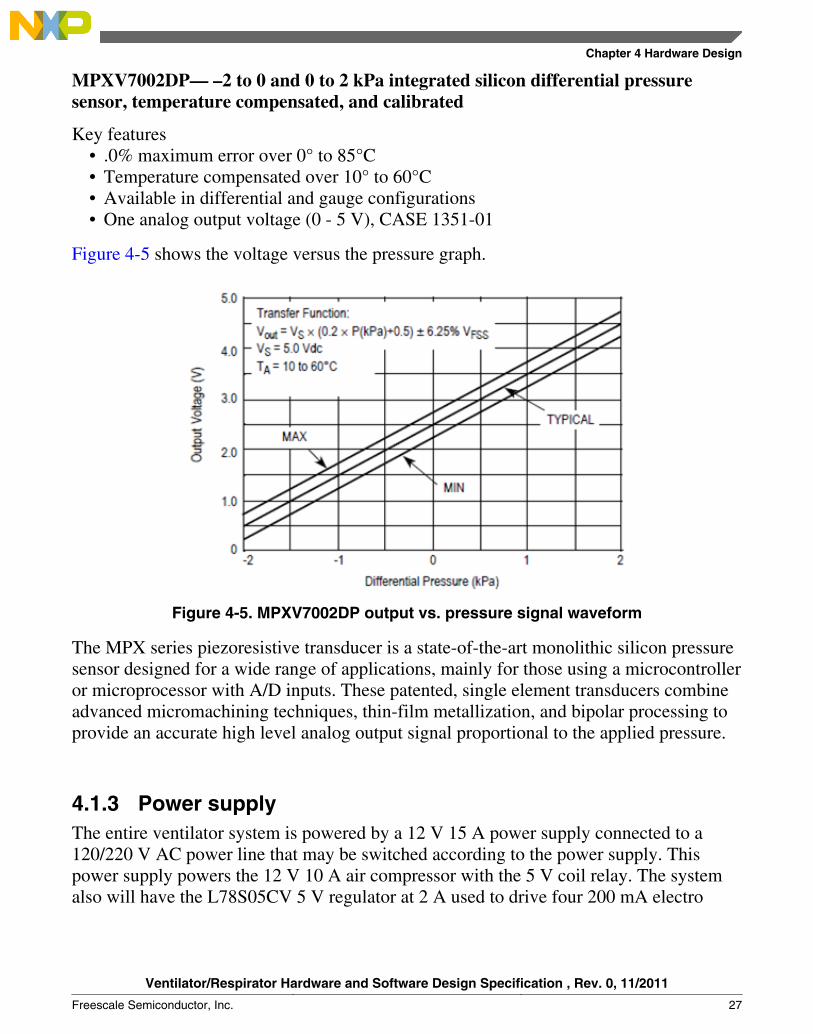
MPXv5100GP— 0 to 100 kPa integrated silicon pressure sensor, temperaturecompensated, and calibrated
Key features:• 2.5% maximum error over 0° to +85°C• Ideally suited for microprocessor or microcontroller-based systems• Temperature compensated over -40°C to +125°C• One analog output voltage (0 - 3.3 V), CASE 1369-01
Figure 4-4 shows the voltage versus the pressure graph.
Figure 4-4. MPXV5100GP output vs. pressure signal waveform
System definition
Ventilator/Respirator Hardware and Software Design Specification , Rev. 0, 11/2011
26 Freescale Semiconductor, Inc.
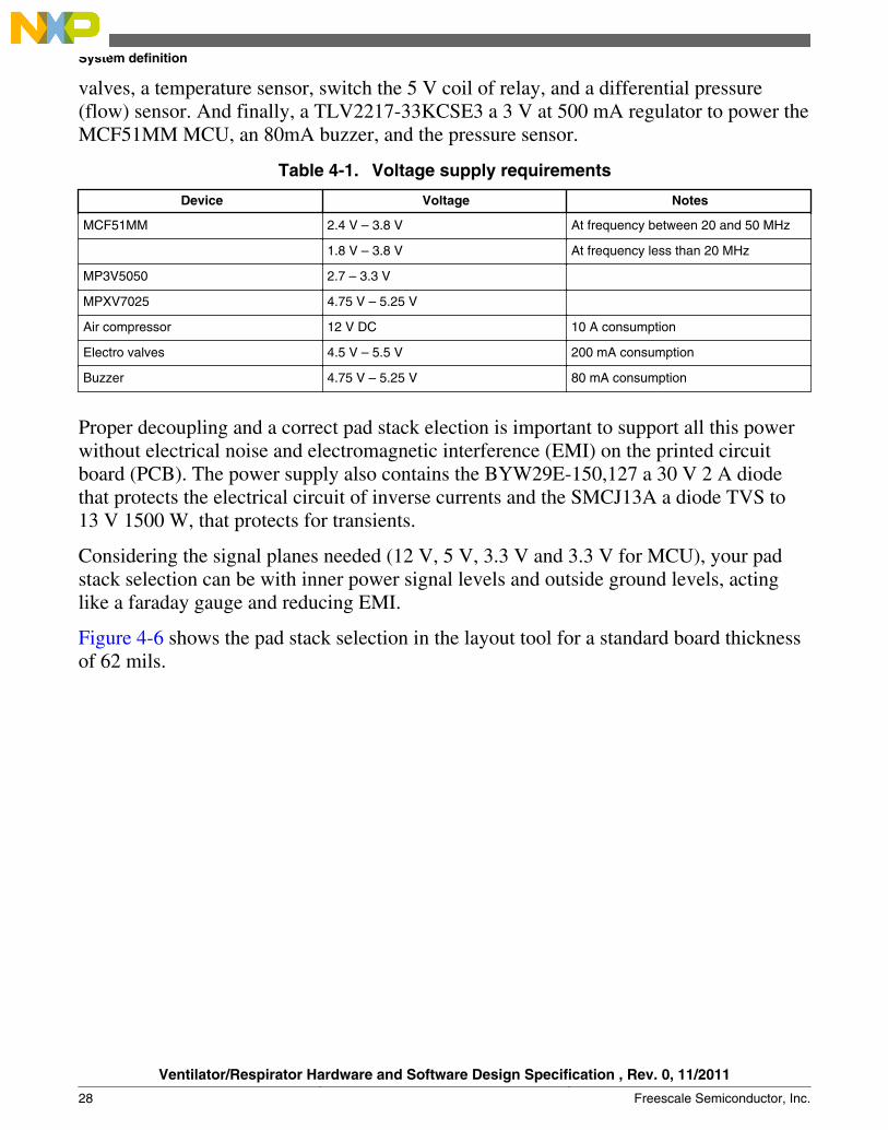
MPXV7002DP— –2 to 0 and 0 to 2 kPa integrated silicon differential pressuresensor, temperature compensated, and calibrated
Key features• .0% maximum error over 0° to 85°C• Temperature compensated over 10° to 60°C• Available in differential and gauge configurations• One analog output voltage (0 - 5 V), CASE 1351-01
Figure 4-5 shows the voltage versus the pressure graph.
Figure 4-5. MPXV7002DP output vs. pressure signal waveform
The MPX series piezoresistive transducer is a state-of-the-art monolithic silicon pressuresensor designed for a wide range of applications, mainly for those using a microcontrolleror microprocessor with A/D inputs. These patented, single element transducers combineadvanced micromachining techniques, thin-film metallization, and bipolar processing toprovide an accurate high level analog output signal proportional to the applied pressure.
4.1.3 Power supplyThe entire ventilator system is powered by a 12 V 15 A power supply connected to a120/220 V AC power line that may be switched according to the power supply. Thispower supply powers the 12 V 10 A air compressor with the 5 V coil relay. The systemalso will have the L78S05CV 5 V regulator at 2 A used to drive four 200 mA electro
Chapter 4 Hardware Design
Ventilator/Respirator Hardware and Software Design Specification , Rev. 0, 11/2011
Freescale Semiconductor, Inc. 27
valves, a temperature sensor, switch the 5 V coil of relay, and a differential pressure(flow) sensor. And finally, a TLV2217-33KCSE3 a 3 V at 500 mA regulator to power theMCF51MM MCU, an 80mA buzzer, and the pressure sensor.
Table 4-1. Voltage supply requirements
Device Voltage Notes
MCF51MM 2.4 V – 3.8 V At frequency between 20 and 50 MHz
1.8 V – 3.8 V At frequency less than 20 MHz
MP3V5050 2.7 – 3.3 V
MPXV7025 4.75 V – 5.25 V
Air compressor 12 V DC 10 A consumption
Electro valves 4.5 V – 5.5 V 200 mA consumption
Buzzer 4.75 V – 5.25 V 80 mA consumption
Proper decoupling and a correct pad stack election is important to support all this powerwithout electrical noise and electromagnetic interference (EMI) on the printed circuitboard (PCB). The power supply also contains the BYW29E-150,127 a 30 V 2 A diodethat protects the electrical circuit of inverse currents and the SMCJ13A a diode TVS to13 V 1500 W, that protects for transients.
Considering the signal planes needed (12 V, 5 V, 3.3 V and 3.3 V for MCU), your padstack selection can be with inner power signal levels and outside ground levels, actinglike a faraday gauge and reducing EMI.
Figure 4-6 shows the pad stack selection in the layout tool for a standard board thicknessof 62 mils.
System definition
Ventilator/Respirator Hardware and Software Design Specification , Rev. 0, 11/2011
28 Freescale Semiconductor, Inc.

Figure 4-6. Pad stack selection
4.1.4 Analog To Digital Converter (ADC)
To measure sensor analog signals for pressure calculating, the system needs an accurateADC. The MM MCU has 24 ports with 16-bit ADC that can be used to read differentsensors. Another useful feature for this MCU is the Op Amp output that can beinterconnected via software to the ADC channel. This is useful for simplifying routing orfor prototyping phases.
In this case, two pressure sensors and one temperature sensor are connected directly tothe ADC, while the signal from two differential pressure sensors are connected from theoutputs of the Op Amps.
Before signals go to the ADC, it is necessary to amplify them or improve them, here theinternal General Purpose Op Amps (GPAMP) is a useful module that is able to probeconfigurations, gain values, and other input and output processes. In this case the outputof the Digital to Analog converted is internally connected as an input of the GPAMP toimprove the signal amplification. DAC can be used to change the reference voltage andprevent cutting signals.
Chapter 4 Hardware Design
Ventilator/Respirator Hardware and Software Design Specification , Rev. 0, 11/2011
Freescale Semiconductor, Inc. 29

4.1.5 Keyboard Interruptions (KBI)
The use of KBIs for the interface buttons eliminates the necessity for extra componentsdue to the internal pull-ups, and simplifying code by directly turning on interrupts. OneKBI port per button is needed.
4.1.6 Universal Serial Bus (USB)
USB is a commonly used communication channel for medical applications. Medicalstandards are moving to create its own USB class and subclasses (PHDC) to create majormedical device environments that can offer the user better health care services.
4.1.7 General Purpose Input Outputs (GPIO)
The system needs GPIOs to control the LCD display, switch valves, and the compressor.The MCU has the Drive Strength feature to provide more current when needed, forexample for the actuators.
The GPIO pulses must reflect the MCU control decisions. To control electrical andelectromechanic actuators the power stage must have enough current requirementsavoiding electrical noise generation trying to reduce and prevent components damagerisks
4.2 Bill Of Materials (BOM)A list of all the components for this demo are shown in the table below.
Table 4-2. Bill of materials
Item # ReferenceDesignator
Manufacturer part#
Manufacturer'sName
Description QTY RoHS Compliant(Yes or No)
PCBA BOM
1 BH1,BH2,BH3,BH4 MOUNTING HOLE NA NA 4 NA
2 C1,C13,C14 UWT1V470MCL1GS
Nichicon CAP 47UF 35VELECT WT SMD
3 Yes
3 C2,C3,C5,C6,C7,C8, C10,(C11DNP),(C12DNP),C15,C16,C17,C20,C21,C28,C29,C30,C31,C32
GRM21BR71H104KA01L
Murata Electronics CAP CER .1UF50V 10% X7R 080
17 Yes
Table continues on the next page...
Bill Of Materials (BOM)
Ventilator/Respirator Hardware and Software Design Specification , Rev. 0, 11/2011
30 Freescale Semiconductor, Inc.

Table 4-2. Bill of materials (continued)
Item # ReferenceDesignator
Manufacturer part#
Manufacturer'sName
Description QTY RoHS Compliant(Yes or No)
4 C4 EEE-1EA100SR Panasonic - ECG CAP ELECT 10UF25V VS SMD
1 Yes
5 C9 GRM216R71H103KA01D
Murata Electronics CAP CER 10000PF50V 10% X7R 0805
2 Yes
6 C19,C34 EEE-1HA4R7AR Panasonic - SSG CAP ELECT 4.7UF50V VS SMD
2 Yes
7 C22,C23,C24,C25,C26,C27
DNP DNP DNP 0 DNP
8 C35 GRM21BR71H474KA88L
Murata Electronics CAP CER .47UF50V X7R 0805
1 Yes
8 D18 BYW29E-150,127 NXP DIODE RECTUFAST 150VTO220AC
1 Yes
9 D2,D8,D9,D10,D11,D12,D13
B230A-13-F Diodes Inc DIODESCHOTTKY 30V2A SMA
6 Yes
10 D14 LNJ406K5YUX Panasonic - SSG LED AMBER S-JTYPE 0805
1 Yes
11 D15 LNJ306G5UUX Panasonic - SSG LED GREEN S-JTYPE 0805
1 Yes
12 D16 LNJ806K5SRX Panasonic - SSG LED SOFTORANGE S-JTYPE 0805
1 Yes
13 D17 TLHK5800 Vishay/Semiconductors
LED 5MM RED1000MCDALINGAP GAAS
1 Yes
14 D19 SMCJ13A Littelfuse Inc DIODE TVS 13V1500W UNI 5%SMC
1 Yes
15 J1,J2,J3,J4,J5,J6 1725656 Phoenix Contact CONN TERMBLOCK 2.54MM2POS
6 Yes
16 J12 1-640456-6 Tyco Electronics LCD CONNHEADER VERT16POS .100 TIN
1 Yes
17 J13 87227-3 Tyco Electronics CONN HEADERVERT .100 6POS15AU
1 Yes
18 J14,J15 Jumper 3Pin 3-644456-3 CONN HEADERVERT 3POS .100TIN
2 Yes
19 J16 UX60A-MB-5ST Hirose Electric CoLtd
CONN RECEPTMINI USB2.0 5POS
1 Yes
Table continues on the next page...
Chapter 4 Hardware Design
Ventilator/Respirator Hardware and Software Design Specification , Rev. 0, 11/2011
Freescale Semiconductor, Inc. 31

Table 4-2. Bill of materials (continued)
Item # ReferenceDesignator
Manufacturer part#
Manufacturer'sName
Description QTY RoHS Compliant(Yes or No)
20 LS2 CSQG703BP CUI Inc BUZZER MAG2.0KHZ 3V 12MM
1 Yes
21 L1,L2,L3 BLM21PG221SN1D
Murata FERRITE CHIP220 OHM 2000MA0805
3 Yes
22 L4,L5 BKP1608HS271-T Taiyo Yuden FERRITE BEAD270 OHM 0603
2 Yes
23 Q1,Q2,Q3,Q4,Q5 IP31C FairchildSemiconductor
TRANS NPNEPITAX 100V 3ATO-220
5 Yes
24 R1 ERJ-6GEYJ472V Panasonic - ECG RES 4.7K OHM1/8W 5% 0805SMD
1 Yes
25 R2,R9 ERJ-6GEYJ331V Panasonic - ECG RES 330 OHM1/8W 5% 0805SMD
2 Yes
26 R3 ERJ-6GEYJ105V Panasonic - ECG RES 1.0M OHM1/8W 5% 0805SMD
0 Yes
27 R4,R5,R6,R7,R12 ERJ-6ENF4700V Panasonic - ECG RES 470 OHM1/8W 1% 0805SMD
5 Yes
28 R8 ERJ-6GEYJ181V Panasonic - ECG RES 180 OHM1/8W 5% 0805SMD
1 Yes
29 R10,R11 ERJ-6GEYJ221V Panasonic - ECG RES 220 OHM1/8W 5% 0805SMD
2 Yes
30 R13 ERJ-6GEYJ103V Panasonic - ECG RES 10K OHM1/8W 5% 0805SMD
1 Yes
31 R14 3352W-1-103LF Bourns Inc. POT 10K OHMTHUMBWHEELCERM ST
1 Yes
32 R15,R23 ERJ-6ENF1693V Panasonic - ECG RES 169K OHM1/8W 1% 0805SMD
2 Yes
33 R16,R24 ERJ-6GEYJ334V Panasonic - ECG RES 330K OHM1/8W 5% 0805SMD
2 Yes
34 R17,R18,R19,R20,R21,R22
ERJ-6GEY0R00V Panasonic - ECG RES 0.0 OHM1/8W 0805 SMD
6 Yes
35 R25,R26 RMCF0805JT33R0 StackpoleElectronics Inc
RES 33 OHM 1/8W5% 0805 SMD
2 Yes
Table continues on the next page...
Bill Of Materials (BOM)
Ventilator/Respirator Hardware and Software Design Specification , Rev. 0, 11/2011
32 Freescale Semiconductor, Inc.

Table 4-2. Bill of materials (continued)
Item # ReferenceDesignator
Manufacturer part#
Manufacturer'sName
Description QTY RoHS Compliant(Yes or No)
36 SW1 KSR221GLFS C&K Components SWITCH TACTSILVR 200GFGULLWING
1 Yes
37 SW2,SW3,SW4,SW5,D16
640456-2 Tyco Electronics IBUTTON TACTILEPROBE CONNHEADER VERT2POS .100 TIN
5 Yes
38 TP1 T POINT TH NA NA 0 NA
39 U2 MCF51MM256CLL FreescaleSemiconductor
32 bits MedicalMCU
1 Yes
40 U5 L78S05CV STMicroelectronics IC REG POSITIVE2A 5V TO-220
1 Yes
41 U6 TLV2217-33KCSE3 Texas Instruments IC LDO REG FXD-VOLT 3.3V TO-220
1 Yes
42 U15 4N27M FairchildSemiconductor
OPTOCOUPLERTRANS-OUT 6-DIP
1 Yes
43 U10 MPXV5100GP FreescaleSemiconductor
IC PRESSURESENSOR 8-SOP14PSI
1 Yes
44 U12 MP3V5050GP FreescaleSemiconductor
IC PRESSURESENSOR 8-SOP7PSI
1 Yes
45 U11,U16 MPXV7025DP FreescaleSemiconductor
PRESSURESENSOR DUALPORT 8-SOP
2 Yes
46 U13 LM94021BIMG/NOPB
NationalSemiconductor
IC TEMP SENSORMULTI-GAINSC70-5
1 Yes
47 U14 JSM1A-12V-5 Panasonic ElectricWorks
RELAY AUTO 15A12VDC SEALEDPCB
1 Yes
48 Y2 NX3225SA-16.000000MHZ
NDK CRYSTAL16.000000 MHZ8PF SMD
0 Yes
System BOM
49 NA MHP1-AS-2-M3 FESTO 2/2 Electrovalvesplate
2 Yes
50 NA MHP1-M4H-2/2G-M3-TC
FESTO 2/2 MiniaturizedElectrovalves
2 Yes
51 NA MHP1-AS-3-M3 FESTO 3/2 Electrovalvesplate
2 Yes
52 NA MHP1-M4H-3/2G-M3-TC
FESTO 3/2 MiniaturizedElectrovalves
2 Yes
Table continues on the next page...
Chapter 4 Hardware Design
Ventilator/Respirator Hardware and Software Design Specification , Rev. 0, 11/2011
Freescale Semiconductor, Inc. 33

Table 4-2. Bill of materials (continued)
Item # ReferenceDesignator
Manufacturer part#
Manufacturer'sName
Description QTY RoHS Compliant(Yes or No)
53 NA QSM-M3-4 FESTO Fittings 8 Yes
54 NA KMH-0,5 FESTO Electrical Valvesconnectors
4 Yes
55 NA QSY-8-4 FESTO Y reductionconnection
1 Yes
56 NA QS-1/4-4 FESTO Reduction 1/4 to 4mm
4 Yes
57 NA 4mm Hose FESTO 4mm air hoses 2 Yes
58 NA 110B 6 2 NA 3/4 to 3/8 reduction 2 Yes
59 NA 110B 12 6 NA 3/8 to 5/32reduction with fastfitting
2 Yes
60 NA D703.19 NA 3/4 CPVC femaladapter
2 Yes
61 NA NA NA Pressure samplingline
1 Yes
62 NA GE Health D-Lite sensor(Venturi)
1 Yes
63 NA GE Health Espirometry hoses 1 Yes
64 NA NA NA Color buttons 4 Yes
65 NA Acteck Computer PowerSupply with powercord
1 Yes
66 NA Pelican Pelican rainstormsuitcase
1 Yes
67 NA Dogma Studio Aluminum panelwith design
1 Yes
68 NA NA Sunmed Anesthetic bag 1 Yes
69 NA NA NA Documentation CD 1 Yes
70 NA NA NA Demo one pagerdocument
1 Yes
71 NA NA Hudson Anesthetic patientcircuit
1 Yes
72 NA 5-87499-8 Tyco Electronics CONN HOUSING30POS .100SINGLE
1 Yes
73 NA NA NA AW 24 Wire 1 Yes
74 NA 5-103171-5 Tyco Electronics CONN SOCKET22-26AWG 30AUCRIMP
30 Yes
75 NA I300 Goodyear Air compressor 1 Yes
Table continues on the next page...
Bill Of Materials (BOM)
Ventilator/Respirator Hardware and Software Design Specification , Rev. 0, 11/2011
34 Freescale Semiconductor, Inc.

Table 4-2. Bill of materials (continued)
Item # ReferenceDesignator
Manufacturer part#
Manufacturer'sName
Description QTY RoHS Compliant(Yes or No)
76 NA 1375820-2 Tyco Electronics CONN RCPTHSNG 2POSCST-100 II - I-button
1 Yes
77 NA 4-643814-6 Tyco Electronics CONN RECEPT16POS 24AWGMTA100 - Display
1 Yes
78 NA C-51847NFJ-SLW-ADN
Optrex America Inc LCD MOD CHAR20X4 WHTTRANSFLECT
1 Yes
79 NA S24453 KeystoneElectronics
STANDOFF HEXM4 THR ALUM10MM
4 Yes
80 NA NA IDEAS Air chamber 1 Yes
4.3 SchematicsIn this section electrical connections are presented by schematic blocks.
4.3.1 MCU blockThe following figure shows the MCU connection tags.
Chapter 4 Hardware Design
Ventilator/Respirator Hardware and Software Design Specification , Rev. 0, 11/2011
Freescale Semiconductor, Inc. 35
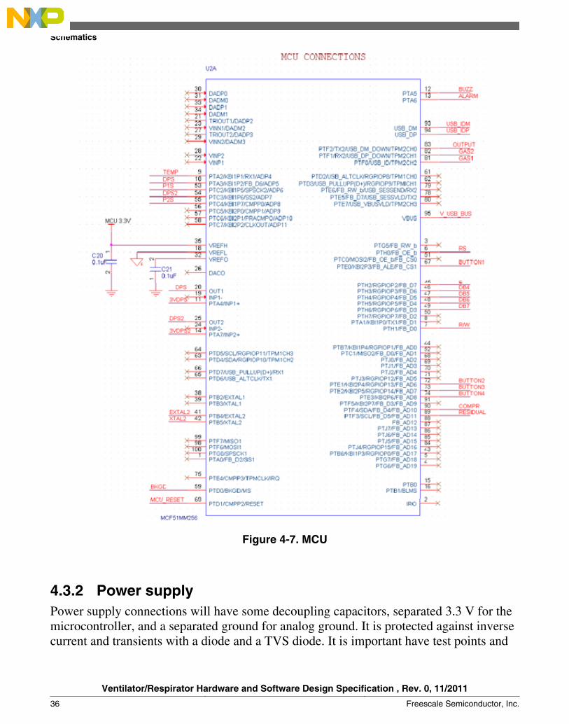
Figure 4-7. MCU
4.3.2 Power supplyPower supply connections will have some decoupling capacitors, separated 3.3 V for themicrocontroller, and a separated ground for analog ground. It is protected against inversecurrent and transients with a diode and a TVS diode. It is important have test points and
Schematics
Ventilator/Respirator Hardware and Software Design Specification , Rev. 0, 11/2011
36 Freescale Semiconductor, Inc.

LEDs for debugging the power supply. Be sure of current capabilities for voltageregulators, to support the entire system. Figure 4-8 shows the actual power supplyschematic diagram.
Figure 4-8. Power supply
4.3.3 BDM and ResetBackground Debug Mode (BDM) and reset are fundamental signals for an appropriatecircuit using Freescale microcontrollers. The BDM is needed to re‐flash program memoryand continue with system developing. And reset helps the user in case of some issues likeexceptions or like a fast restarting program in an emergency case.
Figure 4-9. BDM and reset
Chapter 4 Hardware Design
Ventilator/Respirator Hardware and Software Design Specification , Rev. 0, 11/2011
Freescale Semiconductor, Inc. 37

4.3.4 USB and ClockThe figure below shows USB connections for device mode. It is designed to eliminateelectrical noise, for layout it is important that the USB data routes have similar distancesand a close distance because they are differential signals. These constraints are helpful forsignal integrity. For a correct USB function, the MCU must have an external clock with arecommended frequency of 16 MHZ, if this external clock is not used the USBcommunication can have synchronization issues and frequently disconnect.
Figure 4-10. USB and clock
4.3.5 Actuators switching
Power stages for actuator switching are shown in figure 16. For the air compressor MCUfirst switch a transistor based optoisolator (4N27M) to separate grounds. Then switch therelay coil with 5 V, this coil needs 100 mA to switch, the relay then provides 15 A at 12V for the air compressor.
About valves, MCU ports switch the base of Darlington transistor (TIP31C 500mA) toswitch the 5 V at1 W valves, it means 200 mA.
A resistor to the MCU is needed for both cases to control the MCU pin currentconsumption. The use of RCD snubbers protects inverse currents.
Schematics
Ventilator/Respirator Hardware and Software Design Specification , Rev. 0, 11/2011
38 Freescale Semiconductor, Inc.

Figure 4-11. Actuators switching
4.3.6 AlarmsThis system has two types of alarms for the patient, visual, and audio. Visual is a brightLED, and audio is the buzzer, which uses the same switching circuit as valves to ensurecorrect working. This device can be switched with the PWM or IO with timers.
Figure 4-12. Alarms
Chapter 4 Hardware Design
Ventilator/Respirator Hardware and Software Design Specification , Rev. 0, 11/2011
Freescale Semiconductor, Inc. 39
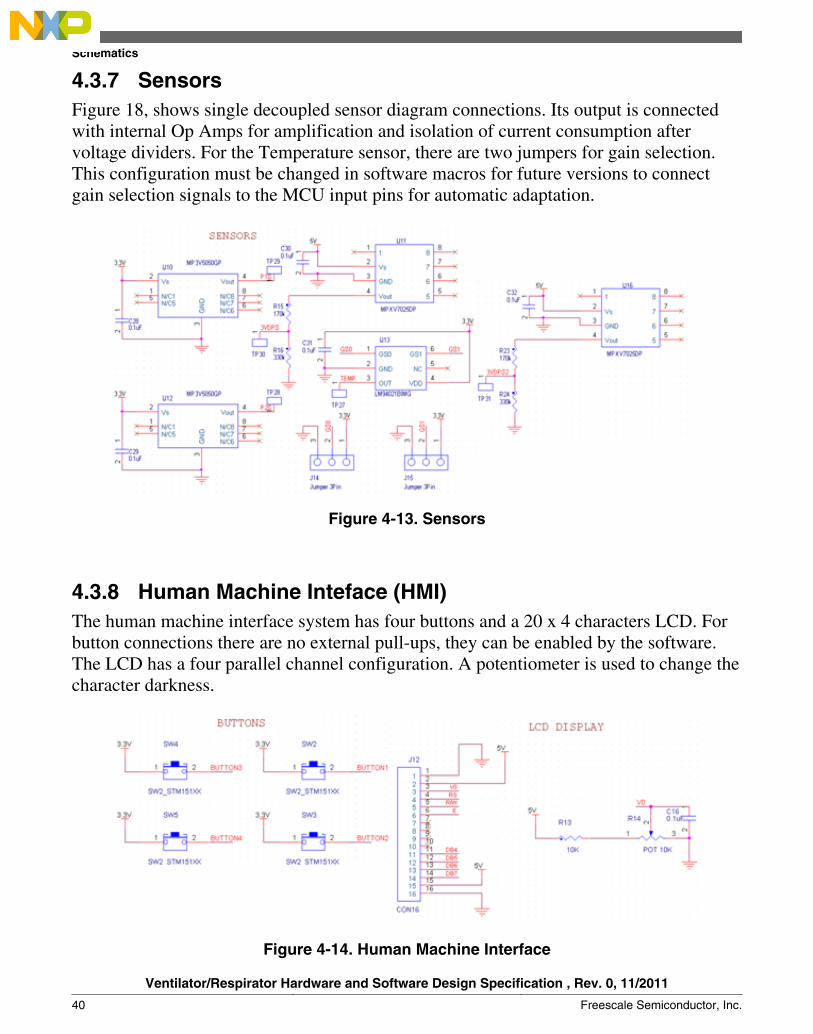
4.3.7 SensorsFigure 18, shows single decoupled sensor diagram connections. Its output is connectedwith internal Op Amps for amplification and isolation of current consumption aftervoltage dividers. For the Temperature sensor, there are two jumpers for gain selection.This configuration must be changed in software macros for future versions to connectgain selection signals to the MCU input pins for automatic adaptation.
Figure 4-13. Sensors
4.3.8 Human Machine Inteface (HMI)The human machine interface system has four buttons and a 20 x 4 characters LCD. Forbutton connections there are no external pull-ups, they can be enabled by the software.The LCD has a four parallel channel configuration. A potentiometer is used to change thecharacter darkness.
Figure 4-14. Human Machine Interface
Schematics
Ventilator/Respirator Hardware and Software Design Specification , Rev. 0, 11/2011
40 Freescale Semiconductor, Inc.

4.4 LayoutCorrect PCB layout maintains signal integration, see the section (3.1.3) Power Supply.
The pad stack chosen:• Top—Ground plane and routing 1.• Inner 1—3.3 V and MCU 3.3 Planes, and air compressor switching plane 1.• Inner 2—5 V and air compressor switching plane 2.• Bottom—Ground plane and routing 2.
4.4.1 Layout designThe layout design created on the Allegro PCB editor program is shown in the followingfigures.
Figure 4-15. Ventilator layout design (top layer—routing and ground plane)
Chapter 4 Hardware Design
Ventilator/Respirator Hardware and Software Design Specification , Rev. 0, 11/2011
Freescale Semiconductor, Inc. 41

Figure 4-16. Ventilator layout design (Power layer 1—3.3 V and the MCU 3.3 V planesand one 12 V switching route)
Layout
Ventilator/Respirator Hardware and Software Design Specification , Rev. 0, 11/2011
42 Freescale Semiconductor, Inc.

Figure 4-17. Ventilator layout design (Power layer 2—5 V plane and one 12 V switchingroute)
Chapter 4 Hardware Design
Ventilator/Respirator Hardware and Software Design Specification , Rev. 0, 11/2011
Freescale Semiconductor, Inc. 43

Figure 4-18. Ventilator layout design (bottom layer—routing and ground plane)
4.4.2 Physical PCBAfter the PCB is manufactured according to gerber files, they look like Figure 4-19 andFigure 4-20.
Layout
Ventilator/Respirator Hardware and Software Design Specification , Rev. 0, 11/2011
44 Freescale Semiconductor, Inc.

Figure 4-19. Ventilator PCB top view without components
Figure 4-20. Ventilator PCB bottom view without components
After the components are assembled the PCB looks like Figure 4-21 :
Chapter 4 Hardware Design
Ventilator/Respirator Hardware and Software Design Specification , Rev. 0, 11/2011
Freescale Semiconductor, Inc. 45
Voltageindicator LEDs
Temperature sensor
Alarm LED
Power supply zone
Power connector
USBconnector
LED connectorLung differentialpressure sensor
Extension differentialpressure sensor
Lung pressuresensors
Tank pressuresensors
Air compressorconnector
ButtonsconnectorValves connector
SwitchingCompressor
switching
MCU
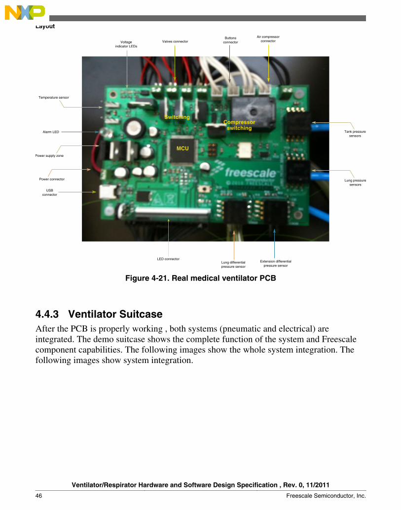
Figure 4-21. Real medical ventilator PCB
4.4.3 Ventilator SuitcaseAfter the PCB is properly working , both systems (pneumatic and electrical) areintegrated. The demo suitcase shows the complete function of the system and Freescalecomponent capabilities. The following images show the whole system integration. Thefollowing images show system integration.
Layout
Ventilator/Respirator Hardware and Software Design Specification , Rev. 0, 11/2011
46 Freescale Semiconductor, Inc.

Air mixture chamber
PowersupplyAir
compressor
Gas pipelines
Electro valves
Venturi pipe
Figure 4-22. Ventilator bottom panel
Figure 4-22 shows the components for the medical ventilator. These components havebeen listed in the BOM. Figure 4-23 shows all the components under the principal panel.
Chapter 4 Hardware Design
Ventilator/Respirator Hardware and Software Design Specification , Rev. 0, 11/2011
Freescale Semiconductor, Inc. 47

Figure 4-23. Ventilator inner components
Figure 4-22 shows the main panel final integration. The main objects are the electronicssystem in the PCB, the HMI, and the anesthetic bag with volume similar to children’slungs (proximally 1.5 L). The air capacity can be controlled by the PCB and configurableby the HMI.
Layout
Ventilator/Respirator Hardware and Software Design Specification , Rev. 0, 11/2011
48 Freescale Semiconductor, Inc.
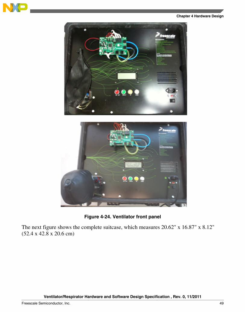
Figure 4-24. Ventilator front panel
The next figure shows the complete suitcase, which measures 20.62" x 16.87" x 8.12"(52.4 x 42.8 x 20.6 cm)
Chapter 4 Hardware Design
Ventilator/Respirator Hardware and Software Design Specification , Rev. 0, 11/2011
Freescale Semiconductor, Inc. 49

Figure 4-25. Complete suitcase
Layout
Ventilator/Respirator Hardware and Software Design Specification , Rev. 0, 11/2011
50 Freescale Semiconductor, Inc.

Chapter 5Software Design
5.1 IntroductionThe software for this demo reference design is not intended to be implemented on a realmedical ventilator, but to briefly show the alternatives to several real cases.
5.2 Software system descriptionDemonstration software must comply with the following points:
• Capability to show all functional modes—Pressure, frequency, and assisted.• Debugging signals—LED in this case will turn on when the system is active in
certain control modes.• Probe main events—Lungs low and high pressure limits, tank low and high pressure
limits, air compressor turns off while the system is active.• Configuration capabilities to change and probe critical values.• Cyclical menus• The user must confirm modifications to prevent any unwanted changes.
Ventilator/Respirator Hardware and Software Design Specification , Rev. 0, 11/2011
Freescale Semiconductor, Inc. 51

Figure 5-1. HMI ventilator flow chart
After the ventilator is in ON mode, the next flow charts proceeds:
Software system description
Ventilator/Respirator Hardware and Software Design Specification , Rev. 0, 11/2011
52 Freescale Semiconductor, Inc.

Figure 5-2. Ventilator function mode flow chart
5.3 Software architectureAfter the software function description was developed, it is important to plan anorganized and portable architecture.
In this case, Freescale C–SAR architecture was used, the following figure is a briefdescription.
Chapter 5 Software Design
Ventilator/Respirator Hardware and Software Design Specification , Rev. 0, 11/2011
Freescale Semiconductor, Inc. 53
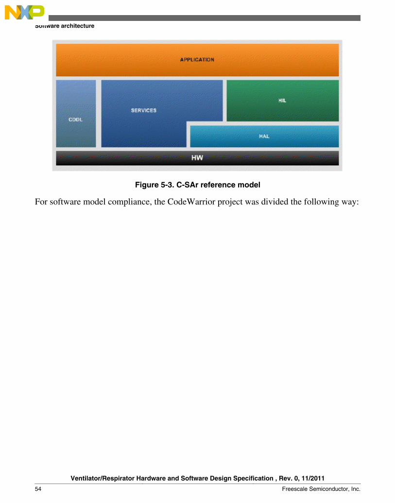
Figure 5-3. C‐SAr reference model
For software model compliance, the CodeWarrior project was divided the following way:
Software architecture
Ventilator/Respirator Hardware and Software Design Specification , Rev. 0, 11/2011
54 Freescale Semiconductor, Inc.

Figure 5-4. CodeWarrior Project structure
This software project structure is explained in the following sections.
5.3.1 Hardware Abstraction Layer (HAL)
This section is about the software made to drive the MCU modules. It reads values orregisters, or write and configure registers perform certain actions or functions.
5.3.1.1 General Purpose Op Amp (GPAMP)
This is the MCU module that controls the internal Op Amps. In this case hardwareconfiguration can be used as a buffer or as non inverter amplifier with a no externalcomponents variable gain.
Chapter 5 Software Design
Ventilator/Respirator Hardware and Software Design Specification , Rev. 0, 11/2011
Freescale Semiconductor, Inc. 55

5.3.1.1.1 GPAMP.c
void vfnInit_GPAMP(void)—This functions starts the Op Amp configuration, thisconfiguration can change according to the gain chosen, Op Amp configuration, and inputand output selection, for this case the DAC output as Op Amp input chosen use to obtaina non Zero reference for amplification.
5.3.1.1.2 GPAMP.h
Contains only relative header files, includes and function declarations.
5.3.1.2 General Purpose Inputs Outputs (GPIO)
This module configures I/O pins used to read or write on the pin chosen, like internalpull‐ups for inputs or drive strength for outputs.
5.3.1.2.1 GPIO.c
void vfnInit_GPIO(void)—This function defines pin or port directions (input or output)and sets intial values. In this case valves, air compressor, LCD, buttons and LED can bedriven by I/O.
5.3.1.2.2 GPIO.h
Contains relative header files that include the function declaration and define nick namesfor ports to understand which pin and register is being used.
5.3.1.3 Key Board Interruptions (KBI)
This module is used to launch interruptions when there is a change in a pin. Theinterruption can be by level or by a rising or increasing edge. The use of GPIO internalpull-ups help save components.
5.3.1.3.1 KBI.c• void vfnInit_KBI(void)—Here the MCU configures its KBI module for flanges and
levels, and cleans registers to use.
Software architecture
Ventilator/Respirator Hardware and Software Design Specification , Rev. 0, 11/2011
56 Freescale Semiconductor, Inc.
• __interrupt KBI_ISR_VECTOR void isrKBI2(void)—This function is obtained ateach KBI interruption. In this case it only changes values of global variables thatcorrespond to the state of HMI buttons. These states are used in the HMI menu tomanage program flow.
5.3.1.3.2 KBI.h
Contains relative header file includes, function declaration, and defines nick names forports, pines, interruption vectors, and configuration masks.
5.3.1.4 Timer/ Pulse-Width Modulator (TPM)
This module can be useful in two ways. For using Pulse Width Modulation (PWM)channels, where each one manages its own bandwidth and period, this module can alsouse the channel as a timer without a dedicated pin. In this case this timer is used by thewhole system for synchronous tasks.
5.3.1.4.1 TPM.c• void vfnInit_PWM(void)—In this function the PWM is initialized and configured for
the clock divider, period, mode and interruptions. To use the PWM, the pulse widthregister must be modified (TPMXCnV).
• void vfnInit_Timer1(void)—In this function the TPM channel is configured as atimer with a certain frequency base, in this case for 0.250 ms.
• __interrupt TPM1_OVFL_ISR_VECTOR void isrTimer1(void)—This interruption islaunched when the period base has passed, in this case this timer will modify a globalsynchronous counter and a time based flag for LCD control.
5.3.1.4.2 TPM.h
Contains relative header file includes, function declaration and defines nick names forregisters, configuration masks, interrupt vectors, and constant values obtain a certainfrequency.
5.3.1.5 Multipurpose clock generator (MCG)
This module sets the clock reference for the MCU bus clock; it could be external orinternal under some modes. Frequency for the internal reference clock is selected in thismodule.
Chapter 5 Software Design
Ventilator/Respirator Hardware and Software Design Specification , Rev. 0, 11/2011
Freescale Semiconductor, Inc. 57
5.3.1.5.1 MCG.c
void vfnInit_MCG(void)—This function selects the reference clock, if selected aninternal clock sets its frequency.
5.3.1.5.2 MCG.h
It contains relative header file includes and function declaration.
5.3.1.6 Analog to Digital Converter (ADC)
This module configures the ADC which converts an analog measure to digital. It can beconfigured, and in this case it also needs to dedicate a function to read the channel.
5.3.1.6.1 ADC.c• void vfnADC_Init(UINT16 gu16Channel_mask)—This function configures and
prepares the ADC channel for use, it needs an input parameter to choose which ADCchannel will be configured.
• UINT32 gu32ADC_Read(UINT8 gu8Channel)—This function selects a channel toread and make the conversion to digital values, in this case it is a blocker task
5.3.1.6.2 ADC.h
It contains relative header files includes, function declarations, configuration maskconstants, and definitions for ADC channel numbers.
5.3.1.7 Digital to Analog Converter (DAC)
This module configures the DAC to a certain analog value from digital values. The MMmicrocontroller is able to communicate certain outputs with certain inputs, in this caseDAC, which will be used as reference for internal OpAmps.
5.3.1.7.1 DAC.c
void DAC12_Vin_SWtrig(void)—Initializes DAC module and configures it. In this casealso set fixed values to use as a voltage reference.
5.3.1.7.2 DAC.h
It contains relative header files, includes and function declarations.
Software architecture
Ventilator/Respirator Hardware and Software Design Specification , Rev. 0, 11/2011
58 Freescale Semiconductor, Inc.

Hardware Independent Layer (HIL)
5.3.2.1 Sensors
These files are used to manipulate the values measured by the sensors, using the ADCand digital filters, performing the respective conversions.
5.3.2.1.1 Sensors.cINT32 gs32FIR_Low_Pass_Filter (INT32 lu32Data, INT32* X_lp_out, INT32* X_lp)—This function is used to improve the signal measured from the sensors taking care of lastmeasurement, and making the rate of change slower in case of a bad measurement. showsfilter function blocks.
Figure 5-5. Low pass Function block and function description
With this filter the band width or frequency cut off can be defined with the followingequation:
Eqn. 10
Where SR is the sample rate of the MCU, N is the number of samples.
It can be used in the following way:
X_lp[1] = lu32Data + X_lp[0] ‐ X_lp[0]/K_LP;
X_lp_out[1] = lu32Data + X_lp ‐ X_lp/K_LP; //X_lp_out[1]=lu32Data/K_LP +X_lp_out[0]‐ X_lp_out[0]/K_LP;
5.3.2
Chapter 5 Software Design
Ventilator/Respirator Hardware and Software Design Specification , Rev. 0, 11/2011
Freescale Semiconductor, Inc. 59

• UINT32 gu32Temperature_Measure(UINT8 lu8_sensor_mask, UINT8lu8_Sensor_Model)—This function calls the ADC port to read and convert thetemperature value to mV. According to the sensor model and configuration ofjumpers 1 and 2 (gain selectors), it sets the correct formula to obtain the temperaturein °C.
• UINT32 gu8Flow_Volume_Measure(UINT32* lu32flow, UINT32* lu32volume,UINT8 lu8_sensor_mask, UINT32 Desired_Volume) —This function first gets theADC value from its respective port and converts it to mV. Flow direction can bedetected considering that in a DP sensor middle voltage corresponds to a pressure of0PA. After direction is known, the next absolute values are considered in thatdirection, until it changes. Instant values are for flow and incremental ones are forvolume.
The following equation is then applied:
Eqn. 11
Where K is the sensor factor value, you have the total pressure for x measurements. Itthen needs to be multiplied by the CAPTURE_TIME factor to convert it to volume (ml).This value indicates the volume goes in same direction, and finally the function returnsthe direction and the application layer uses it.
5.3.2.1.2 Sensors.h
It contains relative header files, includes and function declarations, along with the nextdefinitions:
• SENSOR_FACTOR—It is the K of the system, it means the relation betweenpressure and flow for this specific system.
CAPTURE_TIME—It is the time that takes to do a measurement. Definitions forpressure and temperature sensor models. Definition of measurement states (pressure andvolume). Definition of sensors limits.
5.3.2.2 LCD
These files contain the main LCD driver for the general application.
5.3.2.2.1 LCD.cThis file contains the main controller driver for the LCD screen; here is a briefexplanation of the general functions.
Hardware Independent Layer (HIL)
Ventilator/Respirator Hardware and Software Design Specification , Rev. 0, 11/2011
60 Freescale Semiconductor, Inc.

• UINT8 vfnClear_Screen(void)—Clean the screen with a simple call. It returns 1, ifthe screen is clean.
• UINT8 vfnInit_LCD(void)—Initialization for LCD screen, to configure thecommunication and data transmission. It returns 1 if the initialization has beensuccessful.
• UINT8 vfnPrint_Line(UINT8 *gu8line, UINT8 gu8Size)—This function prints oneline for a given number of characters and a pointer to the first data to be printed. Itreturns 1 when the string is printed and complete.
• UINT8 vfnBlink(UINT8 Cursor_State)—Function that blinks the characters in thecursor position that is referenced with its input variable Cursor_State. Returns 1 ifblinking is working.
• UINT8 vfnSet_Line(UINT8 gu8address)—Set LCD to a horizontal line to print onthe selected line.
5.3.2.2.2 LCD.h
Contains relative header files, includes, states definition, and function declarations forLCD.c.
Services
5.3.3.1 General Services
Files containing the general functions for application services, like discrete controllers,bit operation functions, and delay functions.
5.3.3.2 Services.c
This file contains the following functions.
• UINT32 ug32Negative_To_Positive(UINT32 u32Negative)—This function returnsthe complement for a negative number to get the actual value of the variable.
• INT32 s32_PID_Function (unsigned int Actual_P, unsigned int Desired_P) )—Thisfunction acts as a discrete PID which can be called periodically to control one plant.For inputs you need a reference, the actual read value, and for outputs get thecompensator for the controller.
5.3.3
Chapter 5 Software Design
Ventilator/Respirator Hardware and Software Design Specification , Rev. 0, 11/2011
Freescale Semiconductor, Inc. 61
5.3.3.3 Services.h
Contains relative header files, macros, includes, and function declarations for services.c.
5.3.4 Measurement and conversion services
These files help the application make some calculations about unit conversions.
5.3.4.1 Metering _Algorithm .cThis file contains some algorithms used for metering or for special operations.
• word SquareRoot(dword A)—This function returns square root calculations.
5.3.4.2 Metering _Algorithm .h
Contains relative header files, includes, and function declarations forMetering_Algorithm.c.
5.3.5 Application
This layer is where all the system functions are applied to give a particular function.
5.3.5.1 Main.c
Initialization section:
All files from HIL and service layers are included to call the files. Global variables arealso defined, menu variables, and the constant definition of menu messages. There is asection for all variables where the value can be configurable through the GUI.
Before entering the infinite loop, this program calls all init functions in the lower layerslike MCG, PWM, ADC, KBI, GPIO, GPAMP, interruptions, and the LCD for the systemto use. After init the LCD system performs a welcome message sequence using theproper order of LCD functions.
Measurement section:
Services
Ventilator/Respirator Hardware and Software Design Specification , Rev. 0, 11/2011
62 Freescale Semiconductor, Inc.

Inside the infinite loop system it first measures the temperature to make correct pressuremeasurements, then it refreshes both pressure values (lungs and tank) to show and haveadequate control. After each measurement it prepares an average to show the user.
The differential pressure sensor can output flow volume and flow direction to a certainflow over a minimum point. After this measurement it can calculate the average forinstant flow and by using the flow direction can add or subtract the volume quantity toshow the volume delta after the system starts. This happens because this system does notinclude a method to measure initial volume, therefore the measuring flow uses thedifference, which can be enough to take care of most patients.
Menu section:
After a certain time, values on the display are refreshed with considerable speed. The datashown is transferred by pointers to always show two values and the Freescale demomessage. This menu has to be round cyclic, depending on the value of the variablelu8Active_Menu.
Inside this menu each parameter shows the parameter name, value and unit, or just thename and value, so each parameter divides the line in the appropriate number ofcharacters for each part of the message. There are some parameters able to change itsunits, and with a predefined quantity of possible values. There are message selectors tothese cases.
In this section, the menu performance is dependent on the system mode. In configurablemode there is a cursor on the first character that blinks, this indicates that it can bechanged.
Functional section:
The functional mode for the ventilator can be separated in two parts, the tank mixturecontrol and patient respiration control. This system has a unique way to control mixture,it has three methods to control breathing.
When the start state variable is TRUE, the system is on, and the MCU tries to have themixture within an acceptable pressure range. If it is out of this range it has to allow moremixture in or let out mixture, this depends on its needs. In case it needs more mixture avisual and auditory alarm will be activated—in an ideal case this never will occur—therefore it intentionally lets the pressure drop until the alarm gets activated and restartsthe compressor, in an ideal case this is always on.
The MCU needs to control valves to fill it with the exact amount of gas using the mixturepercentage formulas for pressure. The system monitors the desirable pressure level foreach gas. The Tank_State is then equal to the MIXTURE_READY, in this case thepatient respiration can be executed.
Chapter 5 Software Design
Ventilator/Respirator Hardware and Software Design Specification , Rev. 0, 11/2011
Freescale Semiconductor, Inc. 63
The three alternatives to control breathing in this current design are by:• frequency• pressure• interactively
Frequency—Defines how many respirations a minute are needed and how longinspiration and expiration (in terms of percentage) take. With these values, it calculateshow many milliseconds to wait for each breathing phase, when the timer counter reachesthis value it makes the transition to the next phase
Pressure—Defines low and high pressure limits for respiration. The system continuouslychecks lung pressure. When the pressure comes down to a low limit, inspiration starts;and when pressure reaches the high limit, expiration starts.
Interactive—In this mode, the system gets the balloon pressure to the desired low limitand keeps it at the same value as possible. It then detects pressure increases to a certainvalue and completes the inspiration cycle until the correct high value is met.
These modes have two critical limits, a low and a high limit. First you need know to if alack or leakage of gas exists, in this case an alarm is activated. The high limit is to avoida pressure level that can be dangerous for the patient or in this case the balloon. If thishappens it lets out exceeding gas and then comes back to normal operation.
You can modify any variable used as reference to control the system functions via theHMI.
Configuration section:
This section uses the Display_State variable that can have two values configurable oridle, if it is idle the buttons have the following results:
• UP—Increases the menu counter if it is on the highest return to the lowest, thereforemodifying this counter in the menu section shifts the menu up.
• DOWN—Decreases the menu counter if it is on the lowest return to the highest,therefore modifying this counter in the menu section shifts the menu down.
• SELECT—Changes Display_State variable to configurable and turns on a flag toindicate to the menu, to turn on the blinking function.
After Display_State variable is on, the configurable state buttons have the followingeffects:
• UP—Effects depend on which parameter is modified, in some cases it can increasevalues. It keeps the highest value after it is reached. In other cases it goes cyclic orchanges to the next state.
Services
Ventilator/Respirator Hardware and Software Design Specification , Rev. 0, 11/2011
64 Freescale Semiconductor, Inc.
• DOWN—Effects depend on which parameter is modified, it can decrease values insome cases. It keeps the lowest value after it is reached. In other cases it goes cyclicor returns to the last state.
• SELECT—It turns off the blinking menu flag and changes the Display_State variableto an idle state. The system then refreshes values used when system is on.
5.3.5.2 Config.h
The Config.h file has all defines used in the main section and describes the limits,sensors, and all the variable limits that can be modified. There are some sections,explained below; the file can be divided easily.
Configuration states section:
General defines to configure or not configure the main parameters since the main menu.CONFIG_IDLE and CONFIG_PARAMETERS are the main defines of this short butimportant section.
Configuration Parameters Menu section:
This section defines the main parameters used in the main section to select parameterconfigurations.
This parameters menu is composed of:LUNGS_PRESSURETANK_PRESSUREOPERATION_MODETEMPERATUREOXYGEN_PERCENTAGETANK_LOW_PRESSURETANK_HIGH_PRESSUREALARM_TIMELUNGS_LOW_PRESSURELUNGS_HIGH_PRESSUREINSPIRATION_PERCENTAGERESPIRATION_TIMESPRESSURE_UNITSTEMPERATURE_UNITSMENU_LENGTH
Unit definition section:
Chapter 5 Software Design
Ventilator/Respirator Hardware and Software Design Specification , Rev. 0, 11/2011
Freescale Semiconductor, Inc. 65

This section defines the kind of units used for the pressure, and temperature units.Pressure units are defined as MPSI, PA, CMH2O, MMHG, and MBAR; for temperatureunits CELCIUS and FARENHEIT.
General configuration defines section:
General configuration defines are explained in detail.• INSPIRATION_TIME—The percentage of time a person on the ventilator breaths,
the initial value is 25.• EXPIRATION_TIME—This value is the complement of the previous value, and
must always sum 100%.• RESPIRATIONS_PER_MINUTE—The frequency patient is going to breath, the
initial value is 14.• TIME_MODE_IDLE—Time mode idle defines for state machine.• INSPIRATION_STATE—Inspiration state define for state machine.• EXPIRATION_STATE—Expiration state define for state machine.• LUNGS_LOW_LIMIT_PRESSURE—Defines the lower pressure that can be in an
expiration, the initial value is 700 PSI.• LUNGS_HIGH_LIMIT_PRESSURE—Defines the higher pressure that can be in an
inspiration, the initial value is 900 PSI.• LUNGS_HIGH_CRITICAL_PRESSURE—Defines the critical pressure that can be
in any lung, the initial value is 1600 PSI.• TANK_HIGH_LIMIT_PRESSURE—Defines the higher pressure that can stand in
the pressure chamber, this initial value is 14500 PSI.• TANK_LOW_LIMIT_PRESSURE—Defines the lower pressure that must be
maintained in the pressure chamber, this initial value is 12000 PSI.• SENSOR_HIGH_LIMIT_PRESSURE—Defines maximum pressure the sensor can
measure, the limit for the sensor is 14000 PSI.
Operational Modes section:
This section defines the main operation control modes for ventilation (explainedpreviously) PRESSURE_MODE, TIME_MODE, INTERACTIVE_MODE.
Sensors Used section:
In this section the config.h defines the types of sensors to be used for pressuremeasurement. It defines the LUNGS_PRESSURE_SENSOR as MPXV5050GP, theTANK_PRESSURE_SENS0R as MPXV5100GP and the TEMPERATURE_SENSOR asLM94021.
Conversion Factors section:
This section defines all the factors for conversions between all the possible units.
Services
Ventilator/Respirator Hardware and Software Design Specification , Rev. 0, 11/2011
66 Freescale Semiconductor, Inc.

Chapter 6Parameters Configuration
6.1 Parameters configurationMain parameters configure and interact with users while the Freescale ventilator isworking or idle. These parameters give the application software the control that isimplemented, maximum and minimum tank/lung pressure, providing the ventilator withflexibility for a wide range of use. users. Main configuration variables and parameters areexplained in detail.
Table 6-1. Variables and parameters
Name Description Program Variables andrelated defines
Possible Values (initialvalue)
Oxygen percentage This is the quantity of oxygenthe control lets flow inside thetank when the air and oxygenmixture is made.
Oxygen_percentage 0–100 (20)
Breathing frequency It is the frequency at whichthe user breaths, in breathingtimes per minute.
Respiratory_Frequencydefines:
• RESPIRATIONS_PER_MINUTE
6–17 (14)
Tank Low/High LimitPressure
Defines the range of pressurein the tank. If the pressure islower than the limit, thecompressor turns on to refillthe tank to the pressurerequired.
lu32Tank_Low_Limit_Pressurelu32Tank_High_Limit_Pressure Defines:
• TANK_HIGH_LIMIT_PRESSURE
• TANK_LOW_LIMIT_PRESSURE
0–14500 (12000 – 4500)
Table continues on the next page...
Ventilator/Respirator Hardware and Software Design Specification , Rev. 0, 11/2011
Freescale Semiconductor, Inc. 67
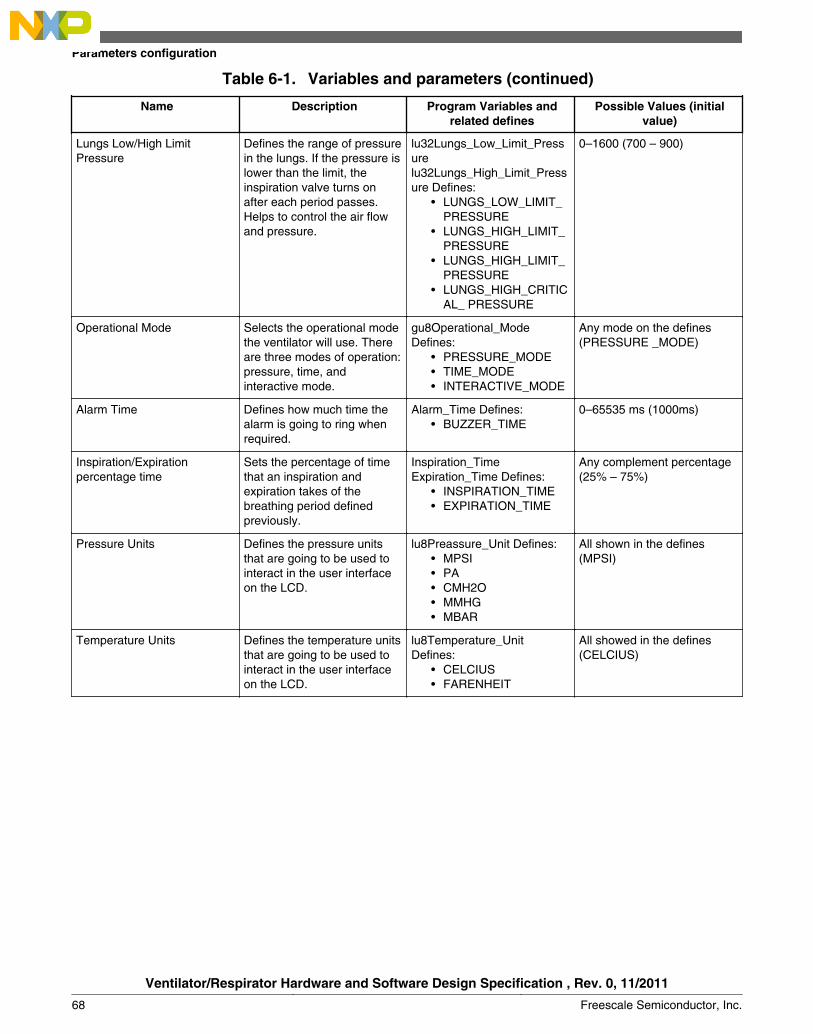
Table 6-1. Variables and parameters (continued)
Name Description Program Variables andrelated defines
Possible Values (initialvalue)
Lungs Low/High LimitPressure
Defines the range of pressurein the lungs. If the pressure islower than the limit, theinspiration valve turns onafter each period passes.Helps to control the air flowand pressure.
lu32Lungs_Low_Limit_Pressurelu32Lungs_High_Limit_Pressure Defines:
• LUNGS_LOW_LIMIT_PRESSURE
• LUNGS_HIGH_LIMIT_PRESSURE
• LUNGS_HIGH_LIMIT_PRESSURE
• LUNGS_HIGH_CRITICAL_ PRESSURE
0–1600 (700 – 900)
Operational Mode Selects the operational modethe ventilator will use. Thereare three modes of operation:pressure, time, andinteractive mode.
gu8Operational_ModeDefines:
• PRESSURE_MODE• TIME_MODE• INTERACTIVE_MODE
Any mode on the defines(PRESSURE _MODE)
Alarm Time Defines how much time thealarm is going to ring whenrequired.
Alarm_Time Defines:• BUZZER_TIME
0–65535 ms (1000ms)
Inspiration/Expirationpercentage time
Sets the percentage of timethat an inspiration andexpiration takes of thebreathing period definedpreviously.
Inspiration_TimeExpiration_Time Defines:
• INSPIRATION_TIME• EXPIRATION_TIME
Any complement percentage(25% – 75%)
Pressure Units Defines the pressure unitsthat are going to be used tointeract in the user interfaceon the LCD.
lu8Preassure_Unit Defines:• MPSI• PA• CMH2O• MMHG• MBAR
All shown in the defines(MPSI)
Temperature Units Defines the temperature unitsthat are going to be used tointeract in the user interfaceon the LCD.
lu8Temperature_UnitDefines:
• CELCIUS• FARENHEIT
All showed in the defines(CELCIUS)
Parameters configuration
Ventilator/Respirator Hardware and Software Design Specification , Rev. 0, 11/2011
68 Freescale Semiconductor, Inc.

Chapter 7Troubleshooting
7.1 TroubleshootingThis section tries to attack main issues that may happen if the system fails. This sectiontries to reduce the impact of some common issues the ventilator may have, like systemerrors and fails.
7.1.1 Main issuesThe ventilator does not turn on when the switch is on—This issue occurs frequently whenthe user does not have an idea on how to get start with the Freescale demonstrationventilator. This issue is easy to fix and takes less then five minutes. To solve this issue trythe next steps:
1. Check that the power cord is connected to the main power source in the suitcase, andconnected to AC voltage.
2. Check that the selected voltage is the correct voltage supplied to the ventilator powersource. The standard value for this is 120 Vrms, but verify if your electricity supplierhas this standard.
3. Listen to the power source ventilator to check if the main board has an issue or thepower source does not work (you may want to unscrew the ventilator to check this).
4. If the previous steps did not work, unscrew the main tap and verify that the powersupply is connected to the main control board. See Figure 7-1 to get better idea onhow the cable must be connected.
Ventilator/Respirator Hardware and Software Design Specification , Rev. 0, 11/2011
Freescale Semiconductor, Inc. 69

Figure 7-1. Power supply connections
Emulator does not completely fill or does not fill at all—Sometimes, even with the soundof air flowing away from the compressor chamber, the lung balloon does not fillcompletely.
This issue occurs mainly when the ventilator has been used many times, or has beentransported in not such good condition. To solve this issue try the steps:
1. Unscrew the main panel to reach the main tubes and valves that control air flowinside the ventilator suitcase.
2. Check that the tubes inside are properly connected, if you see disconnected tubes youcan connect them as shown in Figure 7-2.
Figure 7-2. Valves and hoses connections
Troubleshooting
Ventilator/Respirator Hardware and Software Design Specification , Rev. 0, 11/2011
70 Freescale Semiconductor, Inc.

LCD issues —Display characters sometimes can be wrong or the LCD screen does notturn on properly. To solve this issue try the next steps:
1. Check that the LCD connector cables are plugged in correctly as shown in Figure7-3.
Figure 7-3. LCD connections2. If the LCD is showing some errors in its display, you must place the suitcase far way
from electromagnetic fields such as microwaves, induction stoves, and some cellphones. Then reset the entire demo with the on switch without handling the suitcase.
Compressor does not turn on—Some times the compressor does not turn on the first timeyou push the start button, this issue can be solved with following steps:
1. Check if the power source is on and that the main board LED is also turned on. Ifeverything is on, check the power connections that go from the main PCB board tothe compressor. These connexions are shown in Figure 7-4. The black cables are thecompressor control switch from the main PCB.
Figure 7-4. Power connections2. If the previous example does not work, unscrew the main panel and check that the
compressor power switch is turned on. If not turn the switch on, if this still does notwork, change the entire compressor to verify if the main board works.
Chapter 7 Troubleshooting
Ventilator/Respirator Hardware and Software Design Specification , Rev. 0, 11/2011
Freescale Semiconductor, Inc. 71
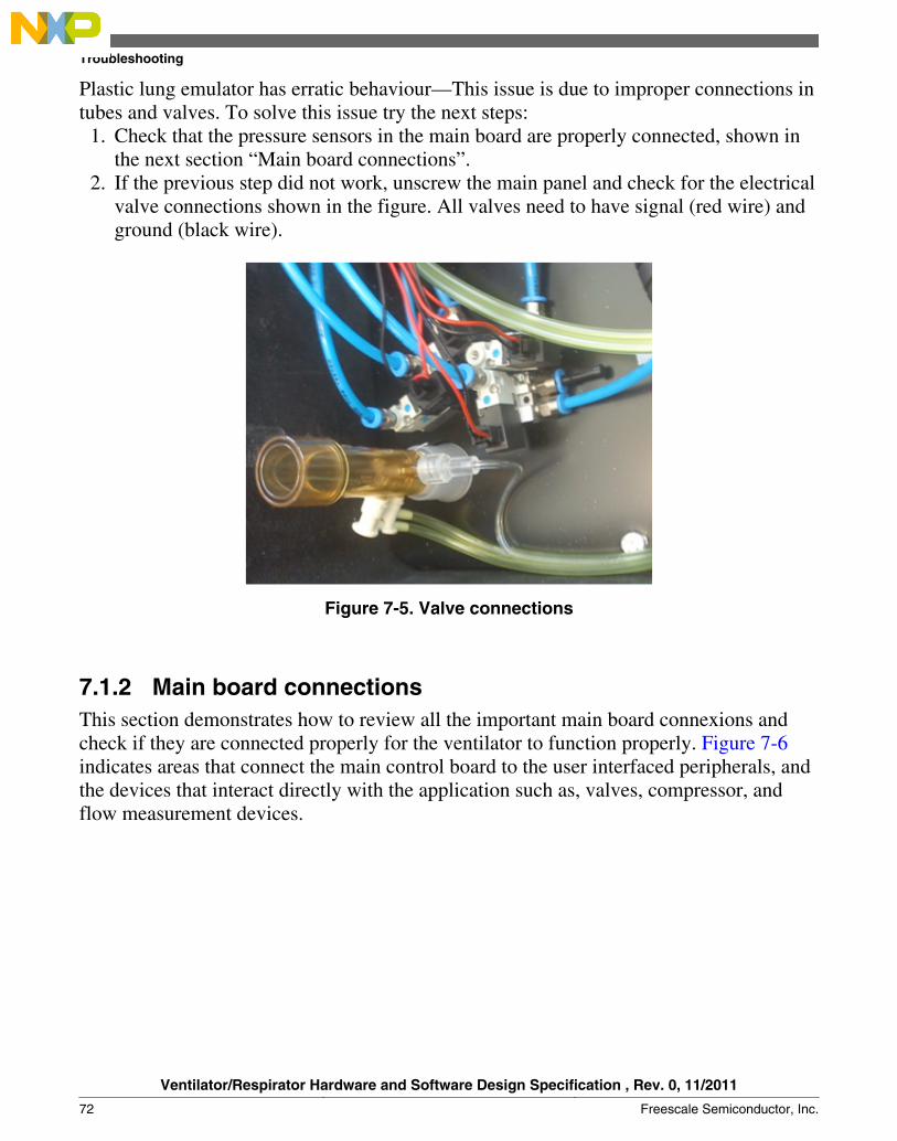
Plastic lung emulator has erratic behaviour—This issue is due to improper connections intubes and valves. To solve this issue try the next steps:
1. Check that the pressure sensors in the main board are properly connected, shown inthe next section “Main board connections”.
2. If the previous step did not work, unscrew the main panel and check for the electricalvalve connections shown in the figure. All valves need to have signal (red wire) andground (black wire).
Figure 7-5. Valve connections
7.1.2 Main board connectionsThis section demonstrates how to review all the important main board connexions andcheck if they are connected properly for the ventilator to function properly. Figure 7-6indicates areas that connect the main control board to the user interfaced peripherals, andthe devices that interact directly with the application such as, valves, compressor, andflow measurement devices.
Troubleshooting
Ventilator/Respirator Hardware and Software Design Specification , Rev. 0, 11/2011
72 Freescale Semiconductor, Inc.

Button connections Compressor power swtch
Connections
Flow and pressure sensors
LCD Connector
USB connector
Main powerconnector
Valve controlsignal connector
Figure 7-6. Main board connections
Button connections—These connections go inside the suitcase. They need to beconnected to control the application through the user interface. If some cables areunplugged, the buttons will not respond.
Compressor power switch—This connector switches the power of the compressor toreach in the air chamber the desired pressure. If this connector is disconnected, thecompressor would not be on.
Flow and pressure sensors—These sensors are connected through tubes that carrypressure inside them. If any of these sensors are disconnected the application could notwork properly. Note that not all sensor must be connected a minimum of three are neededand may be extended for future control needs.
LCD connector—This pin out connector sends the main instructions and power to theLCD board. If this connector is disconnected, the LCD interface will not work.
USB connector—USB connector works as an application interface with other MCUs ordirectly with any computer interface.This connector does not affect the functionality ofthe ventilator, and the interface can be developed in the future.
Chapter 7 Troubleshooting
Ventilator/Respirator Hardware and Software Design Specification , Rev. 0, 11/2011
Freescale Semiconductor, Inc. 73

Main power connector—Power connector supplies the power to the board to accomplishall the main tasks. This connector must be plugged in at all times.
Valve control signal connector—This connector must always be plugged in to control themain valves for the ventilator applications.
Troubleshooting
Ventilator/Respirator Hardware and Software Design Specification , Rev. 0, 11/2011
74 Freescale Semiconductor, Inc.
Chapter 8Conclusion
8.1 Conclusions and ReferencesThis complex and critical medical system for patients demonstrates the effective use ofFreescale components.
• Pressure sensors allow accurate and precise measurements that are required for thiskind of medical application.
• The MCF51MM MCU is an ideal alternative for such applications; it has enoughprocessing power, memory, and speed. Their interfaces (USB) are one of the bestalternatives for the medical industry and its cost effective analog modules. Thesemodules allow flexibility to improvise and experiment with new settings withoutchanging the PCB layout.
References
• MCF51MM256 Reference Manual (document number MCF51MM256RM)• TWR–MCF51MM Schematic• TWR–SER Schematic• MP3V5050• MPXV7002
These documents can be found on the Freescale semiconductor web page,www.freescale.com
Ventilator/Respirator Hardware and Software Design Specification , Rev. 0, 11/2011
Freescale Semiconductor, Inc. 75

Conclusions and References
Ventilator/Respirator Hardware and Software Design Specification , Rev. 0, 11/2011
76 Freescale Semiconductor, Inc.

How to Reach Us:
Home Page:www.freescale.com
Web Support:http://www.freescale.com/support
USA/Europe or Locations Not Listed:Freescale SemiconductorTechnical Information Center, EL5162100 East Elliot RoadTempe, Arizona 85284+1-800-521-6274 or +1-480-768-2130www.freescale.com/support
Europe, Middle East, and Africa:Freescale Halbleiter Deutschland GmbHTechnical Information CenterSchatzbogen 781829 Muenchen, Germany+44 1296 380 456 (English)+46 8 52200080 (English)+49 89 92103 559 (German)+33 1 69 35 48 48 (French)www.freescale.com/support
Japan:Freescale Semiconductor Japan Ltd.HeadquartersARCO Tower 15F1-8-1, Shimo-Meguro, Meguro-ku,Tokyo 153-0064Japan0120 191014 or +81 3 5437 [email protected]
Asia/Pacific:Freescale Semiconductor China Ltd.Exchange Building 23FNo. 118 Jianguo RoadChaoyang DistrictBeijing 100022China+86 10 5879 [email protected]
For Literature Requests Only:Freescale Semiconductor Literature Distribution Center1-800-441-2447 or +1-303-675-2140Fax: [email protected]
Document Number: [No Doc ID]Rev. 0, 11/2011
Information in this document is provided solely to enable system and softwareimplementers to use Freescale Semiconductors products. There are no express or impliedcopyright licenses granted hereunder to design or fabricate any integrated circuits orintegrated circuits based on the information in this document.
Freescale Semiconductor reserves the right to make changes without further notice to anyproducts herein. Freescale Semiconductor makes no warranty, representation, orguarantee regarding the suitability of its products for any particular purpose, nor doesFreescale Semiconductor assume any liability arising out of the application or use of anyproduct or circuit, and specifically disclaims any liability, including without limitationconsequential or incidental damages. "Typical" parameters that may be provided inFreescale Semiconductor data sheets and/or specifications can and do vary in differentapplications and actual performance may vary over time. All operating parameters,including "Typicals", must be validated for each customer application by customer'stechnical experts. Freescale Semiconductor does not convey any license under its patentrights nor the rights of others. Freescale Semiconductor products are not designed,intended, or authorized for use as components in systems intended for surgical implantinto the body, or other applications intended to support or sustain life, or for any otherapplication in which failure of the Freescale Semiconductor product could create asituation where personal injury or death may occur. Should Buyer purchase or useFreescale Semiconductor products for any such unintended or unauthorized application,Buyer shall indemnify Freescale Semiconductor and its officers, employees, subsidiaries,affiliates, and distributors harmless against all claims, costs, damages, and expenses, andreasonable attorney fees arising out of, directly or indirectly, any claim of personal injuryor death associated with such unintended or unauthorized use, even if such claims allegesthat Freescale Semiconductor was negligent regarding the design or manufacture ofthe part.
RoHS-compliant and/or Pb-free versions of Freescale products have the functionality andelectrical characteristics as their non-RoHS-complaint and/or non-Pb-free counterparts.For further information, see http://www.freescale.com or contact your Freescalesales representative.
For information on Freescale's Environmental Products program, go tohttp://www.freescale.com/epp.
Freescale™ and the Freescale logo are trademarks of Freescale Semiconductor, Inc.All other product or service names are the property of their respective owners.
© 2011 Freescale Semiconductor, Inc.