Ventilated facades with Reynobond Architecture aluminium ... · Reynobond ® rivet or screw systems...
19
Specification Text Ventilated facades with Reynobond ® Architecture aluminium composite panels.
Transcript of Ventilated facades with Reynobond Architecture aluminium ... · Reynobond ® rivet or screw systems...
D e d i c a t e d t o y o u r S u c c e s s
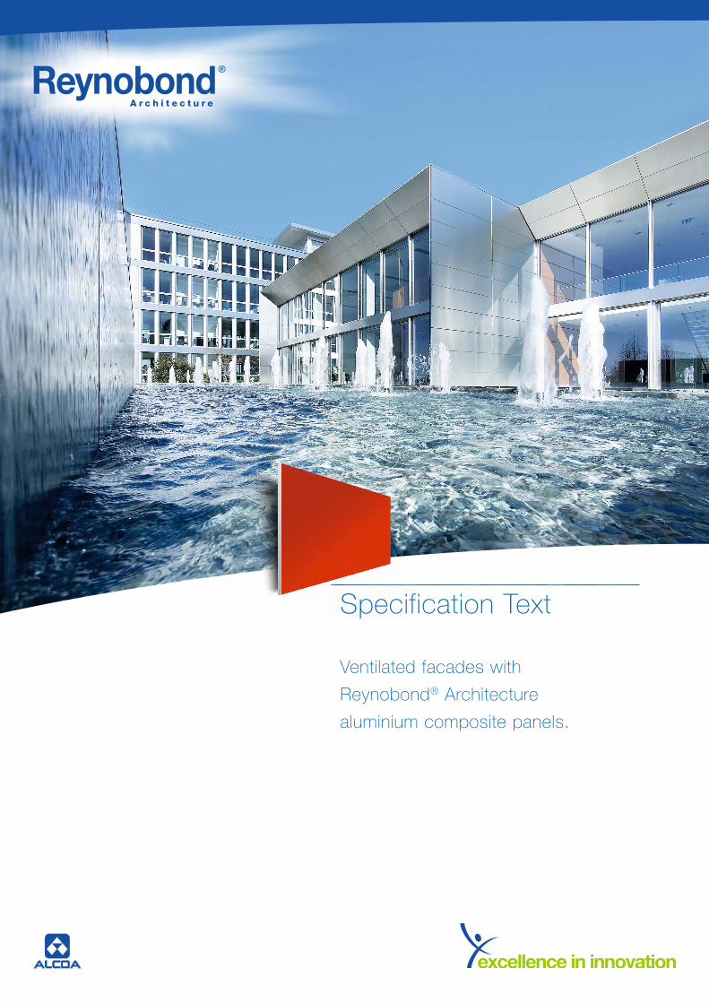
Specification Text
Ventilated facades with
Reynobond® Architecture
aluminium composite panels.

2
Standard – Specification text
Content
Fixing systems Reynobond® ....................................................................................................................................... Cassette, riveted panels or screwed panels)
Orientation ...........................................................................................................................................
(vertical, horizontal)
Information Page
Project information 4Reynobond® product specifications 5 Processing 6Construction 6–9Standards/guidelines 10Estimate and billing 11Scope of services 11
Service description
Construction site set-up 12Scaffolding 12–13Aluminium substructure 14Heat insulation 15Facade cladding 15–18Cleaning 19Summary/service total price 19

44
Information – Project information
Construction plan:
Construction foreman:
Architect:
Construction management:
Building description: New construction Existing building (renovation) Floors G +: ...................................................................
Height of walls (footer – edge of roof): .................. m
Total finished surface: ........................................................ m²
(shadow gaps disregarded)
Shell/outer walls: Concrete ............................................................................. Masonry of ........................................................................
Other ......................................................................................
5
5
Information – Reynobond® composite panel product specifications
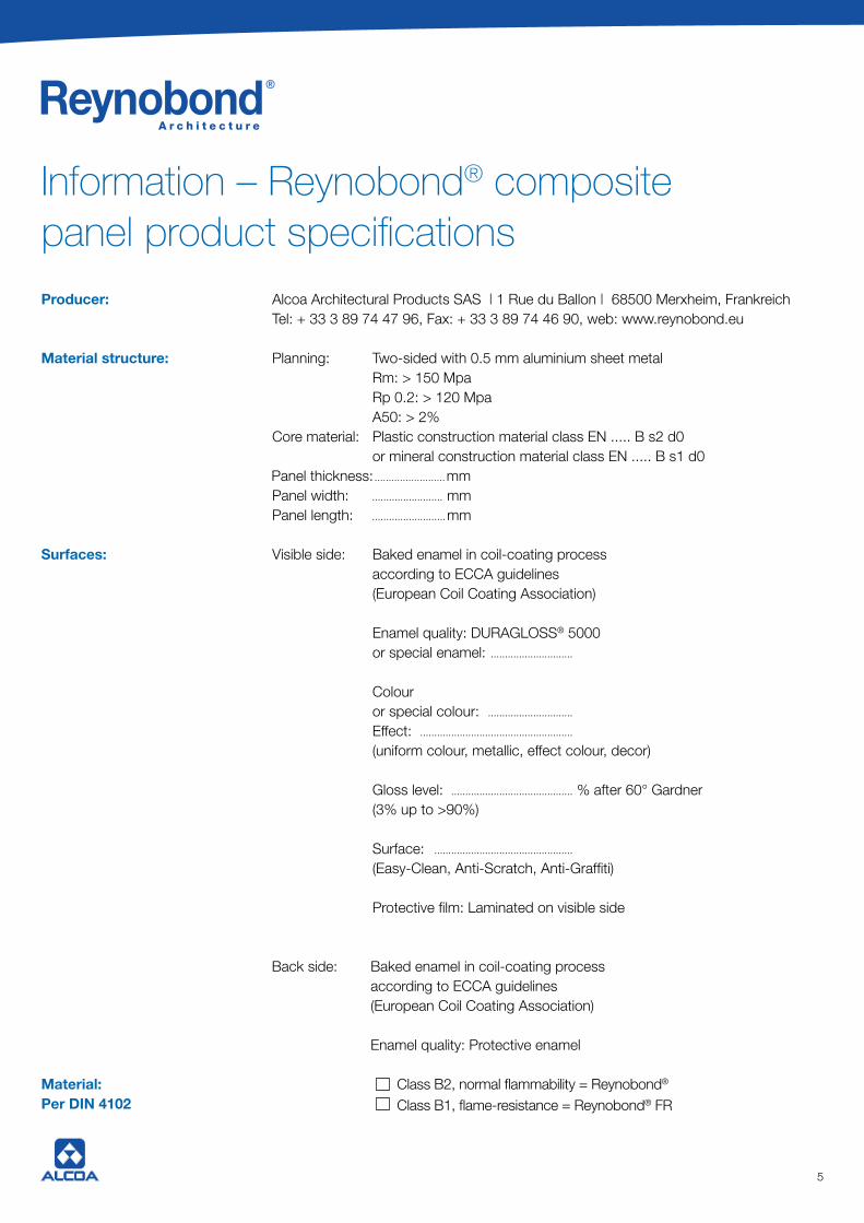
Producer: Alcoa Architectural Products SAS | 1 Rue du Ballon | 68500 Merxheim, Frankreich Tel: + 33 3 89 74 47 96, Fax: + 33 3 89 74 46 90, web: www.reynobond.eu
Material structure: Planning: Two-sided with 0.5 mm aluminium sheet metal Rm: > 150 Mpa Rp 0.2: > 120 Mpa A50: > 2% Core material: Plastic construction material class EN ..... B s2 d0 or mineral construction material class EN ..... B s1 d0 .........................mm Panel width: ......................... mm Panel length: ..........................mm
Surfaces: Visible side: Baked enamel in coil-coating process according to ECCA guidelines (European Coil Coating Association)
Enamel quality: DURAGLOSS® 5000 or special enamel: .............................
Colour or special colour: .............................. Effect: ...................................................... (uniform colour, metallic, effect colour, decor)
Gloss level: ........................................... % after 60° Gardner (3% up to >90%)
Surface: ................................................. (Easy-Clean, Anti-Scratch, Anti-Graffiti)
Protective film: Laminated on visible side
Back side: Baked enamel in coil-coating process according to ECCA guidelines (European Coil Coating Association) Enamel quality: Protective enamel
Material: Class B2, normal flammability = Reynobond® Per DIN 4102 Class B1, flame-resistance = Reynobond® FR
Panel thickness:
5
Information – Reynobond® composite panel product specifications
Producer: Alcoa Architectural Products SAS | 1 Rue du Ballon | 68500 Merxheim, Frankreich Tel: + 33 3 89 74 47 96, Fax: + 33 3 89 74 46 90, web: www.reynobond.eu
Material structure: Planning: Two-sided with 0.5 mm aluminium sheet metal Rm: > 150 Mpa Rp 0.2: > 120 Mpa A50: > 2% Core material: Plastic construction material class EN ..... B s2 d0 or mineral construction material class EN ..... B s1 d0 .........................mm Panel width: ......................... mm Panel length: ..........................mm
Surfaces: Visible side: Baked enamel in coil-coating process according to ECCA guidelines (European Coil Coating Association)
Enamel quality: DURAGLOSS® 5000 or special enamel: .............................
Colour or special colour: .............................. Effect: ...................................................... (uniform colour, metallic, effect colour, decor)
Gloss level: ........................................... % after 60° Gardner (3% up to >90%)
Surface: ................................................. (Easy-Clean, Anti-Scratch, Anti-Graffiti)
Protective film: Laminated on visible side
Back side: Baked enamel in coil-coating process according to ECCA guidelines (European Coil Coating Association) Enamel quality: Protective enamel
Material: Class B2, normal flammability = Reynobond® Per DIN 4102 Class B1, flame-resistance = Reynobond® FR
Panel thickness:

6
6
Information – Processing
Informationen – Construction
The Reynobond® composite panels are as shown in the Reynobond® brochure.
A / Substructures and profile for covered fastening (hanging) with bolts KU 50/35 VA systems
Reynobond® cassette systems are facade cladding based on Reynobond® composite panels designed in cassette form, and mounted using chamfers on a vertically installed support structure of aluminium profiles. These elements are fastened to the building with adjustable angle brackets.
Additional insulation is often installed between the building and cladding, whereby this insulation is ventilated through a ventilation layer running between the insulation layer and the back of the cassettes.
An inserter is inserted into the vertical support rail.
The HC8-TL self-tapping screw which is positioned in the guide allows a prepositioning of the axis in the mounting phase of the cassettes, as well as fine adjustment for better orientation of the splices between the elements. Furthermore, it also allows the blocking of the guides by leading the carrier through the screw holes. The system permits individual dismounting of any cassette element and the creation of splices between cassettes.
The Reynobond® composite panels form a pre-hung rear-ventilated facade, and are mounted on an aluminium substructure.
Manufacturer: ................ Systea ..................................................
Product: ............................... System KU ..........................................
Alloy: ...................................... EN AW 6060 ......................................
Consisting of wall brackets: ................................................... mm
Vertical profiles: ............................... Ref 782 ................................
The distance from the outer wall to the front edge
vertical support profile is: ........................................................ mm

77
B / Substructures and profile for covered fastening (hanging) without boltsKU 50/35 NVA systems
Reynobond® cassette systems are facade cladding based on Reynobond® composite panels designed in cassette form, and mounted using chamfers on a vertically installed support structure of aluminium profiles. These elements are fastened to the building with adjustable angle brackets.
Additional insulation is often installed between the building and cladding, whereby this insulation is ventilated through a ventilation layer running between the insulation layer and the back of the cassettes.
An inserter is inserted into the vertical support rail. The HC8-TL self-tapping screw which is positioned in the guide allows prepositioning in the mounting phase of the cassettes, as well as fine adjustment for better orientation of the splices between the elements. Furthermore, it also allows the blocking of the guides by leading the carrier through the screw holes. The system permits individual dismounting of any cassette element and the creation of splices between cassettes.
The advantage of this variant is the capability of making a vertical splice with no visible axis.
The guides, made of the same profile as the base system, has no transverse axis, but it does have two gaps which are worked into the wings.There are no gaps in the vertical chamfers of the cassettes.
An 80 mm long pipe segment is used, fulfilling two functions: the fastening of the edges, and the folding join of the pip into the gaps in the guide.
The Reynobond® composite panels form a pre-hung rear-ventilated facade, and are mounted on an aluminium substructure.
Manufacturer: .................. Systea ..................................................
Product: ............................... System KU ..........................................
Alloy: .................................... EN AW 6060 ......................................
Consisting of wall brackets: ................................................... mm
Vertical profiles: ............................... Ref 782 ................................
The distance from the outer wall to the front edge
vertical support profile is: ........................................................ mm

88
C / Substructure and profile for visible fastening (rivets or screws)RV 60 4c – SC 60 4c systems
Reynobond® rivet or screw systems are facade cladding based on Reynobond® composite panels which are fastened in sheets on an installed support structure of aluminium profiles. These elements are fastened to the building with adjustable angle brackets.
Additional insulation is often installed between the building and cladding, whereby this insulation is ventilated through a ventilation layer running between the insulation layer and the back of the cassettes.
By painting the rivet heads and screw heads with the colour of the facade panels, aesthetically pleasing colour combinations can be achieved.
The heat expansion of the panels must be taken into consideration. In order to avoid deformation, the expansion gap in the panel must be as large as the expected expansion.
Only blind rivets approved by the building authority may be used.
SAL 3/6-S-D21-4.8x19 screws are specially manufactured for the fastening of Reynobond® panels. They permit the tension-free fastening of the facade panels.
The Reynobond® composite panels form a pre-hung rear-ventilated facade, and are mounted on an aluminium substructure.
Anchoring: Approved anchors and screws
Manufacturer: .................. SYSTEA / SFS ...............................
Product: ............................... Profile .....................................................
Alloy: .................................... EN AW 6060 ......................................
Consisting of wall brackets: ................................................... mm
Vertical profiles: ............................... Ref 782 ................................
The distance from the outer wall to the front edge
vertical support profile is: ........................................................ mm

99
Facade distance: from outer edge of cladding to building structure/fastening base +/– tolerance compensation = ............................................... mm
All fastening, connection and anchoring elements must be made of non-rusting materials. For anchors, suitability must be shown with a certification.
A static calculation must be shown for the panel dimensions, fasteners, connectors, substructure, wall brackets, and anchoring.
The facade structure must be build according to the construction details.
The contractor must present a verifiable static calculation and construction drawings before installation begins.

10
Information – Standard or guidelines to follow
Design loads for buildings DIN 1055Aluminium and aluminium alloys - Sheet, strip, and plate DIN EN 485Extruded aluminium profiles DIN
German construction contract procedures (VOB) Part A: Generalprovisions relating to the award of construction contracts DIN 1960German construction contract procedures (VOB) Part B: Generalprovisions relating to the execution of construction work DIN 1961Fire behaviour of building materials and building components DIN 4102Thermal protection and energy economy in buildings DIN 4108Sound insulation in buildings DIN 4109Aluminium in buildings DIN 4113Service and working scaffolds DIN 4420Factory made mineral wool (MW) products DIN EN 13162Stainless steels DIN 17440Anodized products of wrought aluminium and wrought aluminium alloys DIN 17611Tolerance in building construction tructures DIN 18202VOB part C, General rules applying to all types of construction work DIN 18299VOB part C, Roofing work DIN 18338VOB part C, Work in back-ventilated curtain walling DIN 18351VOB part C, Metalwork DIN 18360Cladding for external walls, ventilated at rear DIN 18516
Rules defining the effects of snow and wind on buildings NV 65Standard test method for peel resistance of adhesives ASTM D 1876Aluminium and aluminium alloys NF EN 485Aluminium and aluminium alloysCoil coated sheet and strip for general applications NF EN 1396Aluminium and aluminium alloys - extruded rod/bar, tube and profiles NF EN 755Metal framework and heat insulation for outside claddingby a echnical pinion or a traditional works observati Cahier CSTB 3194Flammability safety NF P 92-507Fire classification of construction products and elements NF EN 13501
Regional building code
Heat protection codeAccident prevention guidelines of the employer’s liability associationGuidelines for the design and quotation of aluminium construction componentsGuidelines for the use of anchor connections or building-authority approvals of the anchors usedGuidelines for use of flammable construction materials in high-rises (May, 1978) Building authority approval of Reynobond® Z-33.2-1012

1111
In addition to ATV DIN 18299, section 5, the following applies:
General information:
The estimate for the services – regardless of whether it is done by drawing or by dimension – must cover the cladding, substructure, heat and noise insulation, surface treatment and the like for the dimensions of the cladding.
Splices will be ignored.
Uncovered frames, lock bars, stands, beams, and the like up to a 0.3 m individual width will be ignored.
When invoicing by length (m), the largest component length, or for bent components the outer component length, will be measured.
When invoicing by surface area (m²) of individual components with non-right angles or notched surfaces, the smallest enclosing rectangle shall be used.
The following will be deducted:
When invoicing by surface area (m²):gaps in the classing, e.g. openings, niches, of 2.5 m² or greater individual size
When invoicing by length (m):interruptions over 1 m in individual length.
Information – Estimate and billing according to DIN 18351 – VOB Part C, facade work
Scope of services
The manufacturer, delivery, and installation of a prehung, rear-ventilated facade cladding of Reynobond® composite panels including all necessary substructure and construction site set-up, scaffolding, heat insulation, and cleanup.
1212
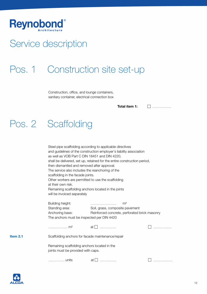
Construction, office, and lounge containers,sanitary container, electrical connection box
Total item 1: ............................
Service description
Pos. 1 Construction site set-up
Pos. 2 Scaffolding
Steel pipe scaffolding according to applicable directives and guidelines of the construction employer’s liability association as well as VOB Part C DIN 18451 and DIN 4220, shall be delivered, set up, retained for the entire construction period, then dismantled and removed after approval. The service also includes the reanchoring of the scaffolding in the facade joints. Other workers are permitted to use the scaffolding at their own risk. Remaining scaffolding anchors located in the joints will be invoiced separately
Building height: ...................................... m² Standing area: Soil, grass, composite pavement Anchoring base: Reinforced concrete, perforated brick masonry The anchors must be inspected per DIN 4420
............................ m² at ........................ ........................... Item 2.1 Scaffolding anchors for facade maintenance/repair
Remaining scaffolding anchors located in the joints must be provided with caps.
........................ units at ........................ ............................

1313
Item 2.2 Protection for passers-by
Above the entrances to doors and gates, for the safety of passers-by, grid supports and passers-by protection shall be provided
......................... running m at ............................. .................................
Total: .................................
Carry-over: .................................
Item 2.3 Scaffolding protective net covering
The surface described under the scaffolding line item shall be covered with a protective scaffolding net (mesh width 2/2 mm). For the net, there must be proof of wind force resistance provided by a materials testing agency. The wind force from this covering must be borne by the scaffolding, which must correspondingly be anchored more firmly. This anchoring strengthening, as well as set-up and dismantling, retention for the entire construction period, must be included in the calculation.
............................ m2 at ............................. .................................
Total item 2: .................................

1414
Service description
Item 3 Aluminium substructure of entire
Facade surface, adjustable, free of warping, corresponding to the formats of the cladding elements for a facade cladding with aluminium Reynobond® composite panels, large-format, with invisible fastening and with approved anchoring elements (e.g. inserts) shall be installed properly and according to statics.
Manufacturer: ................................................................................ Product: .......................................................................................... Alloy: .................................................................................................. Consisting of wall brackets: ....................................... mm Vertical profiles: ........................................................................... The distance from the outer wall to the front edge vertical support profile is: ............................................. mm Anchoring of substructure in the backwards support layer of the building:
............................ m2 at ............................. .................................
Item 3a Aluminium substructure in vicinity of edge, like previous:
............................ m2 at ............................. .................................
Total item 3: .................................

1515
DIN 18165, non-flammable DIN 4102, fastening with insulated brackets, on average 5 units/m², glued in addition, insulation panels of mineral fibre with external fleece coating, black, sides and edges glued over, heat conduction group 035 or 040
Material: ...................................... or equivalent
Fleece coating: Yes no
Thickness: ............... mm
............................ m2 at ................................ Total item 4: ........................
Item 4 Heat insulation for outer wall cladding
Item 5 Facade cladding
Manufacture, delivery, and installation of all-sided edged Reynobond® ...................... according to static requirements and (cassettes, riveted panels, clamped panels)implementation examples
Reynobond® ..................................................... for the substructure listed in item 3 (cassettes, riveted panels, clamped panels) must be hung, oriented, and secured against dislodging.
Grid size vertical: .................................................... mmGrid size horizontal: .................................................... mm
Joint width vertical: .................................................... mmJoint width horizontal: .................................................... mm
Implementation according to implementation examplesReynobond® ....................................... part ........ , page ...........................
(cassettes, riveted panels, clamped panels)
The calculated surface includes the entire processed cladding surface.(shadow gaps disregarded)
............................. m2 at ................................. .............................15
DIN 18165, non-flammable DIN 4102, fastening with insulated brackets, on average 5 units/m², glued in addition, insulation panels of mineral fibre with external fleece coating, black, sides and edges glued over, heat conduction group 035 or 040
Material: ...................................... or equivalent
Fleece coating: Yes no
Thickness: ............... mm
............................ m2 at ................................ Total item 4: ........................
Item 4 Heat insulation for outer wall cladding
Item 5 Facade cladding
Manufacture, delivery, and installation of all-sided edged Reynobond® ...................... according to static requirements and (cassettes, riveted panels, clamped panels)implementation examples
Reynobond® ..................................................... for the substructure listed in item 3 (cassettes, riveted panels, clamped panels) must be hung, oriented, and secured against dislodging.
Grid size vertical: .................................................... mmGrid size horizontal: .................................................... mm
Joint width vertical: .................................................... mmJoint width horizontal: .................................................... mm
Implementation according to implementation examplesReynobond® ....................................... part ........ , page ...........................
(cassettes, riveted panels, clamped panels)
The calculated surface includes the entire processed cladding surface.(shadow gaps disregarded)
............................. m2 at ................................. .............................
1616
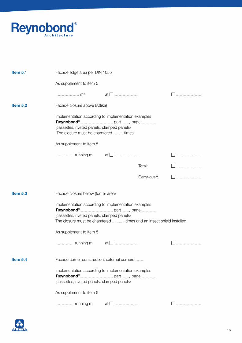
Item 5.1 Facade edge area per DIN 1055
As supplement to item 5
............................ m2 at ............................. .................................
Item 5.2 Facade closure above (Attika)
Implementation according to implementation examplesReynobond® ......................................... part ........., page ....................
(cassettes, riveted panels, clamped panels) The closure must be chamfered ........... times.
As supplement to item 5
..................... running m at ............................. .................................
Total: .................................
Carry-over: .................................
Item 5.3 Facade closure below (footer area)
Implementation according to implementation examplesReynobond® ......................................... part ........., page ....................
(cassettes, riveted panels, clamped panels) The closure must be chamfered ........... times and an insect shield installed.
As supplement to item 5
..................... running m at ............................. .................................
Item 5.4 Facade corner construction, external corners ..........
Implementation according to implementation examplesReynobond® ......................................... part ........., page ....................
(cassettes, riveted panels, clamped panels)
As supplement to item 5
..................... running m at ............................. .................................
1717
Item 5.5 Facade corner construction, internal corners .............
Implementation according to implementation examplesReynobond® ......................................... part ........., page .........................
As supplement to item 5
..................... running m at ............................. .................................
Total: .................................
Carry-over: .................................
Item. 5.6 Facade corner construction above (Attika), external corners .......... 1-part 2-part
Implementation according to implementation examplesReynobond® ......................................... part ........., page .........................
As supplement to item 5
..................... running m at ............................. .................................
Item. 5.7 Facade corner construction above (Attika), internal corners .......... 1-part 2-part
Implementation according to implementation examplesReynobond® ......................................... part ........., page .........................
As supplement to item 5
..................... running m at ............................. .................................
Item. 5.8 Facade window closures, above (lintel area)
Implementation according to implementation examplesReynobond® ......................................... part ........., page .........................
As supplement to item 5
..................... running m at ............................. .................................
Total: .................................
Carry-over: ................................
18
Item 5.9 Facade window closure below/windowsill
Manufactured of Reynobond®® composite panels Reynolux® baked enamel aluminium sheet metal Aluminium profile
Implementation according to implementation examplesReynobond® ............................................... part ........., page .........................
Windowsill depth is ................................................. mm Visible side painted in Reynobond® colour: ............................................................................................ or special colour: ....................................................................................................
As supplement to item 5
.................. running m at ............................. .................................
Item 5.10 Facade window closure, sides/embrasure
Implementation according to implementation examplesReynobond® ............................................... part ........., page .........................
The window embrasure must be chamfered Embrasure depth ...................................................... mm
The window closure will be done with window closure profile ............ Visible side painted in Reynobond® colour: .......................................................................................... or special colour: ...................................................................................................
As supplement to item 5
.................. running m at ................................ Total item 5: ................................
18
19
Cleaning of the facade cladding includes the removal ofcontamination caused by the contractor during manufacturer and installation.Cleaning according to the cleaning recommendations in the Reynobond® brochure shall be carried out.
Total item 6: ......................
Service description
Pos. 6 Cleaning
Summary of items
Item 1 Construction site set-up ..........................................................
Item 2 Scaffolding ..........................................................
Item 3 Aluminium substructure ..........................................................
Item 4 Heat insulation ..........................................................
Item 5 Facade cladding ..........................................................
Item 6 Cleaning ..........................................................
Subtotal, items 1–6 ..........................................................
Plus 16 % VAT of ........................................ ..........................................................
Total: ..........................................................
__________________________________________
City/date
__________________________________________________________
Company stamp and legally binding signature
19

Alcoa Architectural Products
1 rue du Ballon68500 Merxheim, France
Tel. +33 (0) 3 89 74 47 63Fax +33 (0) 3 89 74 46 90
www.alcoaarchitecturalproducts.eu
Alcoa Architectural Products 1, rue du Ballon
68500 Merxheim, FranceTel. +33 (0) 3 89 74 47 96
Fax +33 (0) 3 89 74 46 90 [email protected]
www.reynobond.de
Work with the world market leader! Pho
to c
red
its:
Arb
onia
- F
orst
er -
Hol
ding
AG
Cor
pora
te C
ente
r |
Arb
on,
Sch
wei
tz |
Gis
el &
Par
tner
AG
| U
niba
u.
All
stat
emen
ts h
ere
are
curr
ent a
nd c
orre
ct a
t the
tim
e of
pu
blic
atio
n. A
ll rig
hts
to m
odifi
catio
ns a
nd a
men
dmen
ts
rese
rved
. Thi
s in
form
atio
n m
ay b
e su
bjec
t to
erro
rs th
at m
ay
occu
r du
ring
repd
oruc
tion.
Frie
dlin
g Gr
aphi
que
- Rix
heim
- 03
89
65 5
4 65
- Ce
rtifié
Impr
im’V
ert