
VENT-FREE NATURAL GAS RADIANT FLAM · PDF file · 2007-04-18VENT-FREE NATURAL GAS...
26
VENT-FREE NATURAL GAS RADIANT FLAM HEATER OWNER'S OPERATION AND INSTALLATION MANUAL RFN28TC 14,000 to 28,000 Btu/Hr with Thermostat "C" Model Shown with Optional Mantel featuring Built-in Base I WARNING: If the information in this manual is not followed exactly, a fire or explosion may result causing property damage, personal in- jury, or loss of life. --Do not store or use gasoline or other flammable vapors and liquids in the vicinity of this or any other appliance. -- WHAT TO DO IF YOU SMELL GAS • Do not try to light any appliance. • Do not touch any electrical switch; do not use any phone in your building. • Immediately call your gas supplier from a neighbor's phone. Follow the gas supplier's instructions. • If you cannot reach your gas supplier, call the fire department. m Installation and service must be performed by a qualified installer, service agency, or the gas supplier. WARNING: Improper installa- tion, adjustment, alteration, service, or maintenance can cause injury or property dam- age. Refer to this manual for correct installation and op- erational procedures. Fore assistance or additional in- formation consult a qualified installer, service agency, or the gas supplier. WARNING: This is an unvented gas-fired heater. It uses air (oxygen) from the room in which it is installed. Provisions for adequate com- bustion and ventilation must be provided. Refer to Air for Combustion and Ventilation, page 6 of this manual. This appliance may be Installed in an aftermarket* manufactured (mobile) home, where not prohibited by state or local codes. • Aftermarket: Completion of sale, not for purpose of resale, from the manufacturer
Transcript of VENT-FREE NATURAL GAS RADIANT FLAM · PDF file · 2007-04-18VENT-FREE NATURAL GAS...

VENT-FREE NATURAL GASRADIANT FLAM HEATER
OWNER'S OPERATION AND INSTALLATION MANUAL
RFN28TC
14,000 to 28,000 Btu/Hrwith Thermostat "C"
ModelShown with Optional
Mantel featuringBuilt-in Base
I WARNING: If the information in this manual is
not followed exactly, a fire or explosion mayresult causing property damage, personal in-jury, or loss of life.
--Do not store or use gasoline or otherflammable vapors and liquids in the vicinity ofthis or any other appliance.
-- WHAT TO DO IF YOU SMELL GAS
• Do not try to light any appliance.
• Do not touch any electrical switch; do not useany phone in your building.
• Immediately call your gas supplier from aneighbor's phone. Follow the gas supplier'sinstructions.
• If you cannot reach your gas supplier, call thefire department.
m Installation and service must be performed by aqualified installer, service agency, or the gassupplier.
WARNING: Improper installa-tion, adjustment, alteration,service, or maintenance cancause injury or property dam-age. Refer to this manual forcorrect installation and op-erational procedures. Foreassistance or additional in-
formation consult a qualifiedinstaller, service agency, orthe gas supplier.
WARNING: This is an
unvented gas-fired heater. Ituses air (oxygen) from theroom in which it is installed.
Provisions for adequate com-bustion and ventilation must
be provided. Refer to Air forCombustion and Ventilation,page 6 of this manual.
This appliance may be Installed in an aftermarket* manufactured (mobile) home, where not prohibited bystate or local codes.
• Aftermarket: Completion of sale, not for purpose of resale, from the manufacturer

VENT-FREE NATURAL GAS RADIANT FLAME HEATER
SAFETYINFORMATION
A, WARNINGS
IMPORTANT: Read this owner'smanual carefully and completelybefore trying to assemble, oper-ate, or service this heater. Im-proper use of this heater cancause serious injury ordeath fromburns, fire, explosion, electricalshock, and carbon monoxidepoisoning.
_k DANGER: Carbon monoxide
poisoning may lead to death!
Carbon Monoxide Poisoning: Earlysigns of carbonmonoxide poisoningre-semble the flu, with headaches, dizziness,
or nausea. Ifyou have these signs, the heatermay not be working properly. Get fresh airat onee! Have heater serviced. Some peopleare more affected by carbon monoxide thanothers. These include pregnant women,people with heart or lung disease or anemia,those under the influence of alcohol, and
those at high altitudes.
Natural Gas: Natural gas is odorless. Anodor-making agent is added to natural gas.The odor helps you detect a natural gas leak.However, the odor added to natural gas canfade. Natural gas may be present even thoughno odor exists.
Make certain you read and understand allwarnings. Keep this manual for reference. Itis your guide to safe and proper operation ofthis heater.
_kWARNING: Any changeto thisheater or Its controls can bedangerous.
2.
3.
4.
5.
This appliance is only for use with thetype of gas indicated on the rating plate.This appliance is not convertible for usewith other gases.
Use only natural gas. Do not convertheater to use different fuel type.
If you smell gas• shut off gas supply• do not try to light any appliance• do not touch any electrical switch; do
not use any phone in your building.• immediately call your gas supplier
from a neighbor's phone. Follow thegas supplier's instructions
• if you cannot reach your gas supplier,call the fire department
This heater shall not be installed in abedroom or bathroom.
Never install the heater• in a recreational vehicle• where curtains, furniture, clothing, or
other flammable objects are less than36 inches from the front, top, or sidesof the heater
• asa fireplace insert• in high traffic areas• in windy or drafty areas
6. This heater needs fresh, outside air ven-tilation to run properly. This heater hasan oxygen depletion sensor (ODS) pi-lot light safety system. The ODS shutsdown the heater if not enough fresh airis available. See Air for Combustionand Ventilation, pages 6 through 8.
7. If heater shuts off, do not relight untilyou provide fresh, outside air. If heaterkeeps shutting off, have it serviced.
8. Do not run heater• where flammable liquids or vapors
are used or stored.
• under dusty conditions.
9. Never place any objects on the heater.
10. Surface of heater becomes very hotwhen running heater. Keep children andadults away from hot surface to avoidburns or clothing ignition. Heater willremain hot for a time after shutdown.Allow surface to cool before touching.
ll. Carefully supervise young childrenwhen they are in same room withheater.
12. Make sure screen is in place before run-ning heater.
13. Before using furniture polish, wax, car-pet cleaner, or similar products, turnheater off. If heated, the vapors fromthese products may create a white pow-der residue within burner box or on
adjacent walls or furniture.
14. Do not use heater if any part has been
under water. Immediately call a quali-fied service technician to inspect theroom heater and to replace any part ofthe control system and any gas controlwhich has been under water.
15.
16.
Turn off and unplug heater and let coolbefore servicing. Only a qualified ser-vice person should service and repairheater.
Operating heater above elevations of4,500 feet may cause pilot outage.
_. WARNING: Do not use a I
blower insert, heat exchangerinsert, or other accessory notapproved for use with this heater.
2 I035(_

OWNER'S MANUAL
PRODUCTIDENTIFICATION
Ignitor Button
HeaterCabinet
Log
Figure 1 - Vent*Free Gas Log Natural Gas Space Heater
LOCAL CODESInstall and use heater with care. Follow alllocal codes. In the absence of local codes, usethe latest edition of The National Fuel GasCode ANS Z223, also known as NFPA 54*.
*Available from:
American National Standards Institute, Inc.1430 Broadway
New York, NY 10018
National Fire Protection Association, Inc.Batlerymarch Park
Quincy, MA 02269
Control Knob
/Lighting and
WarningPlates
Note: Do notremove lightingand warningplates fromheater.
Screen
FrontPanel
UNPACKING
CAUTION: Do not remove themetal data plates attached to theheater. The data plates containimportant warranty information.
1. Remove heater from carton.
2. Remove all protective packaging ap-plied to heater for shipment.
3. Make sure your heater includes twohardware packets.
4. Check heater for any shipping damage.If heater is damaged, promptly informdealer where you bought heater.
PRODUCTFEATURESOperation
This heater is clean burning. It requires nooutside venting. This heater has been tested and
approved to ANS Z21.11.2 standard forunvented heaters. State and local codes in some
areas prohibit the use of vent-free heaters.
Safety Pilot
This heater has a pilot with an OxygenDepletion Sensor Shutoff System (ODS).The ODS/pilot is a required feature for vent-free room heaters. The ODS/pilot shuts offthe heater if there is not enough fresh air.
Piezo Ignition System
This heater has a piezo ignitor. This systemrequires no matches, batteries, or othersources to light heater.
Thermostatic Heat Control
This heater has a thermostat sensing bulband a control valve. This results in the great-est heater comfort. This can also result in
lower gas bills.
_oo.._oe 3

VENT-FREE NATURAL GAS RADIANT FLAME HEATER
ASSEMBLY
ASSEMBLING HEATER
Tools Required:
• Phillips screwdriver• 5116" hex wrench
• Slotted screwdriver
Removing Front Panel Of Heater1. Remove two screws near bottom cor-
ners of front panel with Phillips screw-driver.
2. Pull bottom of front panel forward, thendown (see Figure 2).
Figure 2 . Removing Front Panel of Heater
Installing Log
Note: For easier installation, lay heater onits back.
1. Remove log from inside top of heater.Discard protective packaging.
2. Attach ignitor cable to piezo ignitor(see Figure 3).
3. With Phillips screwdriver, remove fourscrews holding screen in place. Re-move screen.
4. Gently slide log between log retainingbrackets on deflector assembly (see Fig-ure 4). The log should fit firmly againstbottom of log retaining brackets.
5. Reattach screen using four screws re-moved in step 3.
_, WARNING: Always haveburner shield and screen in placebefore operating heater. This pre-vents excessive temperatures onheater surfaces.
Failure to position the parts inaccordance with these diagramsor failure to use only parts spe-cifically approved with this heatermay result in property damage orpersonal injury.
Piezo Ignitor
IgnitorCable
Figure 3 -Attaching Ignitor Cable to PlezoIgnitor
LogI
I
Front Panel
Truss-HeadScrew
Brass
Attaching Brass Front Trim toFront Panel
1. Locate brass front trim in brass trimpackage.
2. Slide the head of two truss-head screws
from hardware packet into each end ofbrass front trim (see Figure 5).
3. Line up screws with holes in front panel(see Figure 4). Insert screws in holes.Attach nuts from inside of front panel.Tighten with wrench.
Brass Front
FrontPanel
Screw Nut
Figure 5 - Attaching Brass Front Trim toFront Panel
Heater Cabinet
LogRetaining
. Brackets
BurnerShieldScrew
Figure 4 - Assembling Heater
4 1o35_

OWNER'S MANUAL
ASSEMBLYContinued
Assembling and AttachingBrass Trim
1. Remove packaging from remainingthree pieces of brass trim.
2. Locate four brass screws, two adjust-ing plates with set screws, and twoshims in the hardware packet.
3. Align shim under adjusting plate asshown in Figure 6.
4. Slide one end of adjusting plate/shimin slot on mitered edge of top brass trim(see Figure 6).
5. Slide other end of adjusting plate/shimin slot on mitered edge of side brasstrim (see Figure 6).
6. While firmly holding edges of brasstrim together, tighten both set screwson the adjusting plate with slottedscrewdriver.
7. Repeat steps I through 6 for other side.8. Place the assembled trim on front of
heater cabinet. Attach on top and sideswith four brass screws included in hard-
ware package (see Figure 7).
9. Reattach front panel to heater if you aregoing to mount the heater to the base.Do not re,attach front panel at this timeif you are going to mount heater to wall.
Side Brass Trim Set Screws
AdjustingPlate
Shi;
Mitered Edge
Slot
Figure 6 - Assembling Brass Trim
Slot
Screws
AssembledBrass Trim
Top Brass Trim
Figure 7 - Attaching Brass Trim to Heater
10350S 5

VENT-FREE NATURAL GAS RADIAN'I FLAME HEATER
AIR FORCOMBUSTION ANDVENTILATION
WARNING: This heater shallnot be installed Inaconfined spaceor unusually tight constructionunless provisions are providedfor adequate combustion and ven-tilation air. Read the following in-structions to insure proper freshair for this and other fuel-burningappliances in your home.
Today's homes are built more energy effi-cient than ever. New materials, increasedinsulation, and new construction methodshelp reduce heat loss inhomes. Home ownersweather strip and caulk around windows anddoors to keep the cold air out and the warm airin. During heating months, home ownerswant their homes as airtight as possible.
While it is good to make your home energyefficient, your home needs to breathe. Freshair must enter your home. All fuel-burningappliances need fresh air for proper com-bustion and ventilation.
PROVIDING ADEQUATEVENTILATION
The following are excerpts from NationalFuel Gas Code. NFPA 54/ANS Z223.1, Sec-
tion 5.3, Air for Combustion and Ventila-tion.
All spaces in homes fall into one of the threefollowing ventilation classifications:
1. Unusually Tight Construction
2. Unconfined Space
3. Confined Space
The information on pages 6 through 8 willhelp you classify your space and provideadequate ventilation.
Unusually Tight Construction
The air that leaks around doors and win-
dows may provide enough fresh air forcombustion and ventilation. However, inbuildings of unusually tight construction,you must provide additional fresh air.
Unusually tight construction is de-fined as construction where:
a°
Exhaust fans, fireplaces, clothes dryers, andfuel burning appliances draw air from thehouse to operate. You must provide ad-equate fresh air for these appliances. This b.will insure proper venting of vented fuel-burning appliances.
g.
walls and ceilings exposed to theoutside atmosphere have a con-tinuous water vapor retarder witha rating of one perm (6x10 "11kgper pa-sec-m =)or less with open-ings gasketed or sealed and
weather stripping has beenadded on openable windows anddoors and
caulking or sealants are appliedto areas such as joints aroundwindow and door frames, be-tween sole plates and floors, be-tween wall-ceiling joints, be-tween wall panels, at penetra-tions for plumbing, electrical, andgas lines, and at other openings.
If your home meets all of the threecriteria above, you must provide ad-ditional fresh air° See Ventilation AirFrom Outdoors, page 8.
If your home does not meet all of thethree criteria above, proceed to Deter-mining Fresh-Air Flow for HeaterLocation, page 7.
Confined and Unconfined Space
The National Fuel Gas Code (ANS Z223. l,1992 Section 5.3) defines a confined spaceas a space whose volume is less than 50cubic feet per 1,000 Btu per hour (4.8 m3perkw) of the aggregate input rating of allappliances installed in that space and anunconfining space as a space whose volumeis not less than 50 cubic feet per 1,000 Btuper hour (4.8 m3per kw) of the aggregateinput rating of all appliances installed in thatspace. Rooms communicating directly withthe space in which the appliances are in-stalled*, through openings not furnishedwith doors, are considered a part of theunconfined space.
This heater shall not be installed in a con-fined space or unusually tight constructionunless provisions are provided for adequatecombustion and ventilation air.
* Adjoining rooms are communicating onlyif there are doorless passageways or ventila-tion grills between them.
6 f_

OWNER'S MANUAL
AIR FORCOMBUSTION ANDVENTILATIONContinued
DETERMINING FRESH-AIR FLOW FOR HEATER LOCATION
Determining if You Have a Confined or Unconfined Space
Use this worksheet to determine if you have a confined or unconfined space.
Space: Includes the room in which you will install heater plus any adjoining rooms with doorless passageways or ventilation grills betweenthe rooms.
1. Determine the volume of the space (length x width x height).
Length x Width x Height = cu. ft. (volume of space)
Example: Space size 20 ft. (length) x 16 ft. (width) x 8 ft. (ceiling height) = 2560 cu. ft. (volume of space)
If additional ventilation to adjoining room is supplied with grills or openings, add the volume of these rooms to the total volume ofthe space.
2. Divide the space volume by 50 cubic feet to determine the maximum Btu/Hr the space can support.
(volume of space) ÷ 50 cu. ft. = (Maximum Btu/Hr the space can support)
Example: 2560 cu. ft. (volume of space) ÷ 50 cu. ft. =51.2 or 51,200 (maximum Btu/Hr the space can support)
3. Add the Btu/Hr of all fuel burning appliances in the space.
Vent-free heater Btu/Hr
Gas water heater* Btu/Hr
Gas furnace Btu/FIr Example: Gas water heater 30,000 Btu/Hr
Vented gas heater Btu/Hr Vent-free heater + 28,000 Btu/Hr
Gas fireplace logs Btu/Hr Total = 58,000 Btu/Hr
Other gas appliances* + Btu/Hr
Total = Btu/Hr
* Do not include direct-vent gas appliances. Direct-vent draws combustion air from the outdoors and vents to the outdoors.
4. Compare the maximum Btu/Hr the space can support with the actual amount of Btu/Hr used.
Btu/Hr (maximum the space can support)
Btu/Hr (actual amount of Btu/l-lr used)
Example: 51,200 Btu/Hr (maximum the space can support)
58,000 Btu/Hr (actual amount of Btu/Hr used)
The space in the above example is a confined space because the actual Btu/Hr used is more than the maximum Btu/Hr the space can support.You must provide additional fresh air. Your options are as follows:
A. Rework worksheet, adding the space of an adjoining room. If the extra space provides an unconfined space, remove door to adjoin-ing room or add ventilation grills between rooms. See Ventilation Air From Inside Building, page 8.
B. Vent room directly to the outdoors. See Ventilation Air From Outdoors, page 8.
C. Install a lower Btu/Hr heater, if lower Btu/Hr size makes room unconfined.
If the actual Btu/Hr used is less than the maximum Btu/I-lr the space can support, the space is an unconfined space. You will need noadditional fresh air ventilation.
WARNING: If the area In which the heater may be operated Is smaller than that defined as an unconfined spaceor If the building is of unusually tight construction, provide adequate combustion and ventilation air by one ofthe methods described in the National Fuel Gas Code, ANS Z223.1, 1992, Section 5.3, or applicable local codes.
Continued
103508 7
VENT-FREE NATURAL GAS RADIANT FLAME HEATER
AIR FORCOMBUSTION ANDVENTILATIONContinued
VENTILATION AIR
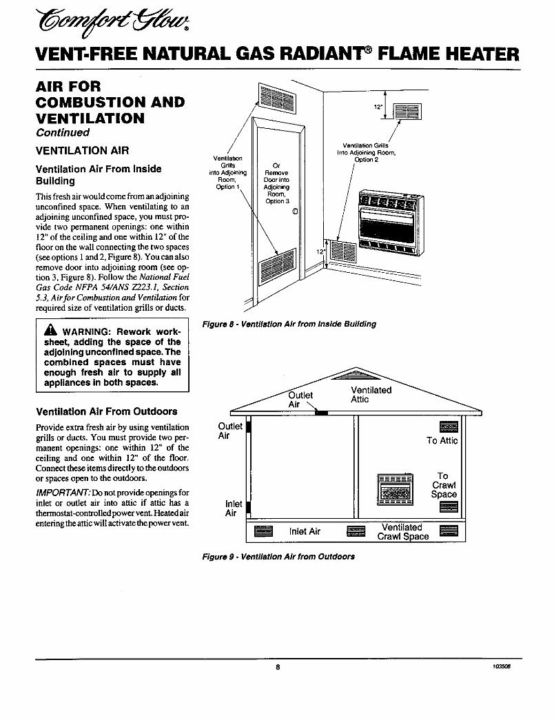
Ventilation Air From Inside
Building
This fresh air would come from an adjoiningunconfined space. When ventilating to anadjoining unconfined space, you must pro-vide two permanent openings: one within12" of the ceiling and one within 12" of thefloor on the wall connecting the two spaces(see options 1 and 2, Figure 8). You can alsoremove door into adjoining room (see op-tion 3, Figure 8). Follow the National FuelGas Code NFPA 54/ANS Z223.1, Section
5.3, Air for Combustion and Ventilation forrequired size of ventilation grills or ducts.
WARNING: Rework work-
sheet, adding the space of theadjoining unconfined space, Thecombined spaces must haveenough fresh air to supply allappliances in both spaces.
VentilationGrills
into AdjoiningRoom,
Option 1
Ventilation Grills
Into Adjoining Room,Option 2
Figure 8 - Ventilation Air from Inside Building
Ventilation Air From Outdoors
Provide extra fresh air by using ventilationgrills or ducts. You must provide two per-manent openings: one within 12" of theceiling and one within 12" of the floor.Connect these items directly to the outdoorsor spaces open to the outdoors.
IMPORTANT: Do not provide openings forinlet or outlet air into attic if attic has a
thermostat-controlled power vent. Heated airentering the attic will activate the power vent.
OutletAir
InletAir
Inlet Air VentilatedCrawl Space
Figure 9 - Ventilation Air from Outdoors
To Attic
ToCrawlSpace
8 1035t_

OWNER'S MANUAL
INSTALLATION
NOTICE: This heater is intendedfor use as supplemental heat. Usethis heater along with your pri-mary heating system. Do not In-stall this heater as your primaryheat source. If you have a centralheating system, you may runsystem's circulating blower whileusing heater. This will help circu-late the heat throughout thehouse. In the event of a poweroutage, you can use this heateras your primary heat source.
NOTICE: A qualified service per-son must install heater. Followall local codes.
CHECK GAS TYPE
Use only natural gas. If your gas supply isnot natural gas, do not install heater. Calldealer where you bought heater for propertype heater.
INSTALLATION ITEMS
Before in,tailing heater, make sure you havethe items listed below.
piping (check local codes)
sealant (resistant to propane/LP gas)manual shutoff valve *
ground joint union
test gauge connection *
sediment trap
tee joint
pipe wrench
• An A.G.A. design-certified manual shutoffvalve with 1/8" NPT tap is an acceptablealternative to test gauge connection. Pur-chase the optional A.G.A. design-certifiedmanual shutoff valve from your dealer. SeeAccessories, pages 24 and 25.
LOCATING HEATER
WARNING: Maintain the mini-mum clearances shown in Figure10. If you can, provide greaterclearances from floor, ceiling, andjoining wall.
You can locate heater on floor. The optionalhearth base is needed. You can also install
the optional decorative mantel on the heater(some mantels require hearth base).IMPORTANT" Only use optional manteland hearth base specified in this manual.Purchase the optional mantel and hearthbase from your dealer. See Accessories,pages 24 and 25.
The heater may also be mounted on a wall.You cannot use optional mantel if mountingheater on a wall.
WARNING: Never install theheater• in a bedroom or bathroom• in a recreational vehicle• where curtains, furniture,
clothing, or other flammableobjects are less than 36 inchesfrom the front, top, or sides ofthe heater
• as a fireplace Insert• in high traffic areas• in windy or drafty areas
_1= CAUTION: This heater cre-ates warm air currents. Thesecurrents move heat to wall sur-faces next to heater. Installingheater next to vinyl or cloth wallcoverings or operating heaterwhere impurities (such as to-bacco smoke, aromatic candles,cleaning fluids, oil or kerosenelamps, etc.) in the air exist, maydiscolor walls.
IMPORTANT: Vent-free heaters add mois-
ture to the air. Although this is beneficial,installing heater in rooms without enoughventilation air may cause mildew to formfrom too much moisture. See Air for Com-bustion and Ventilation, pages 6 through 8.
_, CAUTION: If you install theheater in a home garage
• heater pilot and burner mustbe at least 18 inches abovefloor.
• locate heater where moving ve-hicle will not hit it.
Forconvenience andefficiency, install heater
• where there is easy access for operation,inspection, and service.
• in coldest part of room.
An optional fan kit is available from yourdealer. See Accessories, pages 24 and 25. Ifplanning to use fan, locate heater near anelectrical outlet.
CEIUNG
,36"Minimum
RightSide
S"
---LFLOOR Minimum to Top
Sudace of Carpeting,Tile or OtherCombustible Material
Figure 10 - Mounting Clearances AsViewed From Front of Heater
Continued
_a35o0 9

VENT-FREE NATURAL GAS RADIANT FLAME HEATER
iNSTALLATiONContinued
THERMOSTAT SENSINGBULB
The thermostat sensing bulb has been placedinside the heater for protection during ship-
ping.
Locating Thermostat SensingBulb
1. Remove front panel of heater (see Fig-ure 2, page 4).
2. Locate thermostat sensing bulb justunder burner assembly.
IMPORTANT." Attach thermostat sensingbulb to back of heater for proper operation.
Attaching Thermostat SensingBulb
1. Remove thermostat sensing bulb fromholders inside heater. Route throughslot opening in bottom of heater.
2. Place clamp on thermostat sensing bulbas shown in Figure 11. Clamp is pro-vided in hardware package.
3. Snap clamp into upper mounting holeas shown in Figure I 1. Mounting holeis located on lower left edge on backof heater. Make sure the thermostat
sensing bulb is pointing up.
ThermostatBulb
Clamp
Figure 11 - Attachlng Thermostat SensingBulb
INSTALLATION OPTIONS
There are three options for mounting thisheater.
A. Mounting heater to wall
B. Mounting heater to optional hearth base
C. Mounting heater with optional hearthbase to optional mantel
A. MOUNTING HEATER TOWALL
Mounting Bracket
The mounting bracket is located on backpanel of heater. It has been taped there forshipping. Remove mounting bracket fromback panel.
MountingBracket
Figure 12 - Mounting Bracket Location
Methods For AttachingMounting Bracket To Wall
Only use last hole on each end of mountingbracket to attach bracket to wall. These two
holes are 16inches apart from their centers.Attach mounting bracket to wall in one oftwo ways.
1. Attaching to wall stud
2. Attaching to wallancbor
Attaching To Wall Stud This methodprovides the strongest hold. Insertmountingscrews through mounting bracket and intowall studs.
Attaching To Wall Anchor This methodallows you to attach mounting bracket tohollowwails(wall areasbetweenstuds)orto solidwalls(concreteor masonry).
Decide which method better suits your needs.Either method will provide a secure hold forthe mounting bracket.
Marking Screw Locations
1. Tape mounting bracket to wall whereheater will be located. Make sure
mounting bracket is level.
_WARNING: Maintain minimumclearances shown In Figure 13. Ifyou can, provide greater clear-ances from floor and joining wall.
2. Mark screw locations on wall (see Fig-ure 13).
Note: Only mark last hole on each endof mounting bracket. Insert mountingscrews through these holes only.
3. Remove tape and mounting bracketfrom wall.
\ / IOnly Insert Mounting 20 3/4"Screws Through Last Min.
Hole On Each End
Figure 13. Mounting Bracket Clearances
Attaching Mounting Bracket ToWall
Note: Wall anchors, mounting screws, andspacers are in hardware package. The hard-ware package is provided with heater.
Attaching To Wall Stud Method
For attaching mounting bracket to wall studs
1. Drill holes at marked locations using9/64" drill bit.
2. Place mounting bracket onto wall. Lineup last hole on each end of bracket withholes drilled in wall.
3. Insert mounting screws through bracketand into wall studs.
4. Tighten screws until mounting bracketis firmly fastened to wall studs.
10 t 03.,_a
OWNER'S MANUAL
INSTALLATIONContinued
Attaching To Wall Anchor Method
For attaching mounting bracket to hollowwails (wall areas between studs) or solidwalls (concrete or masonry)
1. Drill holes at marked locations using5/16" drill bit. For solid wails (concreteor masonry), drill at least 1" deep.
2. Fold wall anchor as shown in Figure 14.
3. Insert wall anchor (wings first) intohole. Tap anchor flush to wall.
4. For thin walls (1/2" or less), insertred key into wall anchor. Push redkey to "pop" open anchor wings.IMPORTANT: Do not hammer key!
For thick walls (over 1/2" thick) or solidwalls, do not pop open wings.
5. Place mounting bracket onto wall. Lineup last hole on each end of bracket withwall anchors.
6. Insertmounting screws throughbracketand into wall anchors.
7. Tighten screws until mounting bracketis firmly fastened to wall.
Figure 14 - Folding Anchor
Figure 15- Popping Open Anchor WingsFor Thin Walls
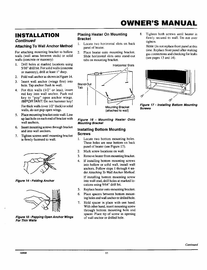
Placing Heater On MountingBracket
1. Locate two horizontal slots on back
panel of heater.
2. Place heater onto mounting bracket.Slide horizontal slots onto stand-out
tabs on mounting bracket.
SStand-OutTab
Horizontal Slots
Mounting Bracket(attached to wall)
Figure 16 - Mounting Heater OntoMounting Bracket
Installing Bottom MountingScrews
2.
3.
4.
1. Locate two bottom mounting holes.These holes are near bottom on back
panel of heater (see Figure 17).
Mark screw locations on wall.
5.
6.
7.
Remove heater from mounting bracket.
If installing bottom mounting screwsinto hollow or solid wall, install wallanchors. Follow steps 1 through 4 un-der Attaching To Wall Anchor Method.
If installing bottom mounting screwinto wall stud, drill holes at marked lo-cations using 9/64" drill bit.
Replace heater onto mounting bracket.
Place spacers between bottom mount-ing holes and wall anchor or drilled hole.
Hold spacer in place with one hand.With other hand, insert mounting screwthrough bottom mounting hole andspacer. Place tip of screw in openingof wall anchor or drilled hole.
8. Tighten both screws until heater isfirmly secured to wall. Do not overtighten.
Note: Do not replace front panel at thistime. Replace front panel after makinggas connections and checking for leaks(see pages 13 and 14).
Figure 17 - Installing Bottom MountingScrews
Continued
w3_a 11

VENT-FREE NATURAL GAS RADIANT a)FLAME HEATER
INSTALLATIONContinued
B. MOUNTING HEATER ONOPTIONAL HEARTH BASE
WARNING: If installing theGHB802 or GHB802A base onheater, and using with a GA se-ries heater blower accessoryalong with a GS601 surround or aGM800 or GM900 series mantel,the surround or mantel clearanceto back wall should be 3/4 inch.This will improve flame appear-ance and combustion.
Use only s GHB802B, GHB802C,or GHB38 series hearth base ifusing a GA series heater bloweraccessory with a GM700 series,GMC32F series, or GMC33U se-ries mantel.
Tools needed:
• #2 Phillips screwdriver
• slotted screwdriver
• electric drill (if securing base to floor)
The optional hearth base kit includes thefollowing:
Hearth Base
4 Wood Screws
4 Sheet Metal Screws
Brass Base Trim
Hearth Insert
4 Anchors
Laminate Sheet & Adhesive
2 Brass Screw_;
Note: It is an option to secure GI-IB802Amodel hearth base to floor. You must securethe GHB802B, GItB802C, or GI-IB38 se-ries model hearth base to floor. To securehearth base to floor, follow instructions un-der Securing Hearth Base to Floor If notsecuring hearth base to floor, proceed toMounting Heater to Optional Hearth Base.
Securing Hearth Base to Floor
1. Position hearth base in desired location.
Mark holes for drilling (See Figure 18).Remove hearth base.
2. For carpeted floor, make a small cut witha sharp knife at marked locations beforedrilling. If securing to a wood floor, drilla 3/4" deep hole using a 1/8" diameterdrill bit. Do not use anchors in woodfloors.
Bottom of HeaterBase
ShippingScrew
3.
Holes forIf securing to a concrete floor, drill a Securing1 Vs" deep hole using a 1/4" diameter Heater to Floorconcrete drill bit. Completely insertanchors into each hole.
Mount heater to hearth base followingsteps under Mounting Heater to Op-tional Hearth Base. After mountingheater, position heater and hearth baseover drilled holes. With slotted screw-
driver, secure hearth base to floor withfour wood screws.
Mounting Heater to OptionalHearth Base
h Lay heater on its back on a table withthe bottom of heater overhanging theedge of the table.
2. Remove 2 shipping screws in bottomof heater. Discard shipping screws.
3. Line up mounting holes on top of hearthbase with holes in bottom of heater (seeFigure 18).
4. Using a Phillips screwdriver, securehearth base to heater with four sheet
metal screws (see Figure 18).
5. Stand heater up on base.6. Place hearth insert in hearth base as
shown in Figure 19.
7. Assemble brass trim (see steps 1through 7 under Assembling and At-taching Brass Trim, page 5).
8. Slide base trim on heater base. Attachbrass trim to base with two brass screws
included as shown in Figure 19.
MountingHoles
\ Sheet MetalScrew
Figure 18 - Attaching Heater to HearthBase
LaminateSheet\
HearthInsert
Screw
_ Brass Base Trim
Figure 19- Placing Hearth Insert on HeaterBase and Attaching Brass Base Trim
12 lo_oe

OWNER'S MANUAL
INSTALLATIONContinued
C. MOUNTING HEATER WITHOPTIONAL HEARTH BASETO OPTIONAL MANTEL Seeinstructions included withmantel kit.
Assembling Mantel
IMPORTANT: Only use the optional man-tels specified in this manual. See Accesso-ries, pages 24 and 25 for proper mantel kits.This heater is only approved for use withmodels GMF800(A,B )/GMU801 (A,B),GMg00F(A,B)/GM901U(A,B), GM700F/GM701U, GMC22F/GMC23U/GMC24U,
GMC32F(B)/GMC33U(B), and GMC26F/GMC27U/GMC28F mantel kits. Using anyother mantel will void the A.G.A. approvalfor this heater. Do not use models
GMF800(A,B)/GMU80 1(A,B),GM900F(A,B)/GM901U(A,B), andGM70OF/GM701U, GMC22F/GMC23U/GMC24U, GMC32F(B)/GMC33U(B), andGMC26F/GMC27U/GMC28F mantels with
any other product. Before installing mantelto heater, the heater must be mounted on the
optional hearth base.
Installing Mantel to Heater
_k WARNING: If installing theGHB802 or GHB802A base onheater, and using with a GA se-ries heater blower accessoryalong with a GS601 surround or aGM800 or GM900 series mantel,the surround or mantel clearanceto back wall should be 3/4 inch.This will improve flame appear-ance and combustion.
Use only a GHB802B, GHB802C,OR GHB38 series hearth base ifusing a GA series heater bloweraccessory with a GM70O series,GMC32F series, or GMC33U se-ries mantel.
CONNECTING TO GASSUPPLY
NOTICE: A qualified service per-son must connect heater to gassupply. Follow all local codes.
WARNING: Never connectheater to private (non-utility) gaswells. This gas is commonlyknown as wellhead gas.
IMPORTANT: Check gas line pressure be-fore connecting heater to gas line. Gas linepressure must be no greater than 14 inchesof water. If gas line pressure is higher,heater regulator damage could occur.
CAUTION : Use only new,black iron or steel pipe. Inter-nally-tinned copper tubing maybe used in certain areas. Checkyour local codes. Use pipe of 1/2"or greater diameter to allowproper gas volume to heater. Ifpipe is too small, undue loss ofpressure will occur.
Installation must include a manual shutoff
valve, union, and plugged 1/8" NPT tap.
Locate NPT tap within reach for test gaugehook up. NPT tap must be upstream fromheater (see Figure 20).
Apply pipe joint sealant lightly to malethreads. This will prevent excess sealantfrom going into pipe. Excess sealant in pipecould result in clogged heater valves.
_k CAUTION: Use pipe ioint seal-ant that is resistant to liquid pe-troleum (LP) gas.
Install sediment trap in supply line as shownin Figure 20. Locate sediment trap where itis within reach for cleaning. Locate sedi-ment trap where trapped matter is not likelyto freeze. A sediment trap traps moistureand contaminants. This keeps them fromgoing into heater controls. If sediment trapis not installed or is installed wrong, heatermay not run properly.
_k CAUTION: Avoid damage tocontrol. Hold gas fitting withwrench when connecting it to gaspiping and/or fittings.
Pressure Note: BurnerRegulator _ bracket not
shown for clarity
3/8" NPTPipe
TestGaugeConnection *
JointCabinet
nual Shutoff Valve *
(4" W.C. to 10.5° W.C.Pressure)
Sediment _;Minimum
Trap
-Cap
Figure 20 - Gas Connection
* An A.G.A. design-certified manual shutoff valve with !/8" NPT tap is an acceptablealternative to test gauge connection. Purchase the optional A.G.A. design-certified manualshutoff valve from your dealer. See Accessories, pages 24 and 25.
Continued
to35_e 13

VENT-FREE NATURAL GAS RADIANT FLAME HEATER
INSTALLATIONContinued
CHECKING GASCONNECTIONS
in_gWARNING: Test all gas pip-" and connections for leaksafter installing or servicing. Cor-rect all leaks at once.
_I_WARNING: Never use an openflame to check for a leak. Apply amixture of liquid soap and waterto all joints. Bubbles formingshow a leak. Correct all leaks atonce.
Pressure Testing Gas SupplyPiping System
Test Pressures In Excess Of 1/2 PSIG
1.
2.
3.
4.
5,
6.
Disconnect heater and its individual
manual shutoff valve from gas supplypiping system. Pressures in excess of1/2 psig will damage heater regulator.
Cap off open end of gas pipe wheremanual shutoff valve was connected.
Pressurize supply piping system by ei-ther using compressed air or
opening main gas valve located on ornear gas meter.
Check all joints of gas supply pipingsystem. Apply mixture of liquid soapand water to gas joints. Bubbles form-ing show a leak.
Correct all leaks at once.
Reconnect heater and manual shutoff
valve to gas supply. Check reconnectedfittings for leaks.
Test Pressures Equal To or Less Than1/2 PSIG
2.
3.
Pressure Testing Heater GasConnections
Close manual shutoff valve (see Fig-ure 2l). 1.
Pressurize supply piping system by ei-ther using compressed air or opening 2.main gas valve located on or near gasmeter. 3.
4.Check all joints from gas meter tomanual shutoff valve (see Figure 22).
Apply mixture of liquid soap and wa-ter to gas joints. Bubbles forming showa leak.
4. Correct all leaks at once.
Manual _ Open
Shutoff ________
Closed
Figure 21 - Manual Shutoff Valve
5.
6.
7.
8.
Open manual shutoff valve (see Fig-ure 21).
Open main gas valve located on or neargas meter.Make sure control knob of heater is inthe OFF position.
Check all joints from manual shutoffvalve to thermostat gas valve (see Fig-ure 22). Apply mixture of liquid soapand water to gas joints. Bubbles form-ing show a leak.Correct all leaks at once.
Light heater (see Operating Heater,pages 15 and 16). Check all other in-ternal joints for leaks.
Turn off heater (see To Turn Off Gas toAppliance, page 15).
Replace front panel.
Thermostat Gas Valve Location
Gas Meter
Figure 22. Checking Gas Joints
ManualShutoffValve
14 _0_5_

OWNER'S MANUAL
OPERATINGHEATER l LIGHTINGINSTRUCTIONS
I FOR YOUR SAFETY l 1.READ BEFORE
LIGHTING 2.
WARNING: If you do not fol-low these instructions exactly, afire or explosion may result caus-ing property damage, personalinjury or loss of life.
A. This appliance has a pilot which mnstbe lighted by hand. When lighting thepilot, follow these instructions exactly.
B. BEFORE LIGHTING smell allaround the appliance area for gas. Besure to smell next to the floor becausesome gas is heavier than air and willsettle on the floor.
WHAT TO DO IF YOU SMELLGAS• Do not try to light any appliance.• Do not touch any electric switch; do
not use any phone in your building.• Immediately call your gas supplier
from a neighbor's phone. Followthe gas supplier's instructions.
• If you cannot reach your gas sup-plier, call the fire departmenL
C. Use only your hand to pash in or turnthe gas control knob. Never use tools.If the knob will not push in or turnby hand, don't try to repair it, call aqualified service technician or gassupplier. Force or attempted repairmay result in a fire or explosion.
D. Do not nse this appliance if any parthas been under water. Immediatelycall a qualified service technician toinspect the appliance and to replaceany part of the control system andany gas control which has been un-der water.
STOP! Read the safety informationabove.
Make sure manual shutoff valve is
fully open.
3. Turn control knob clockwise F-_to the OFF position.
4. Wait five (5) minutes to clear out anygas. Then smell for gas, includingnear the floor. If you smell gas,STOP! Follow "B" in the safety in-formation. If you don't smell gas, goto the next step.
5. Turn control knob counterclockwise
f'_"'_ to the PILOT position. Pressin control knob for five (5) seconds(see Figure 23).
Note: You may be running thisheater for the first time after hook-
ing up to gas supply. If so, the con-trol knob may need to be pressed infor 30 seconds. This will allow air tobleed from the gas system.
6. With control knob pressed in, pushdown and release ignitor button. Thiswill light pilot. The pilot is attachedto the front of burner. If needed, keeppressing ignitor button until pilotlights.
Note: If pilot does not stay lit, referto Troubleshooting, pages 17 through19. Also contact a qualified serviceperson or gas supplier for repairs.Until repairs are made, light pilot withmatch. To light pilot with match, seeManualLighting Procedure , page 16.
Ignitor ControiButton Knob
7. Keep control knob pressed in for 30seconds after lighting pilot. After 30seconds, release control knob.• If control knob does not pop up
when released, contact a qualifiedservice person or gas supplier forrepairs.
Note: If pilot goes out, repeat steps3 through 7. This heater has a safetyinterlock system. Wait one (1) minutebefore lighting pilot again.
8. Turn control knob counterclockwise
to desired heating level. Themain burner should light. Set controlknob to any heat level between HIand LO.
Thermocouple Ignitor ElectrodePilot Burner
Figure 24 - Pilot
_,CAUTION: Donottrytoadjust Iheating levels by using themanual shutoff valve.
TO TURN OFF GAS 1TO APPLIANCE
Shutting Off Heater
1. Turn control knob clockwiseto the OFF position.
2. Turn off all electric power to the ap-pliance if service is to be performed.
Shutting Off Burner Only (pilotstays lit)
1. Turn controlknob clockwiseto the PILOT position.
Figure 23 - Control Knob In The OFFPosition
Continued
_035_ 15

VENT-FREE NATURAL GAS RADIAN'IP FLAME HEATER
OPERATINGHEATERContinued
I THERMOSTAT ICONTROL OPERATION
The thermostatic control used on thisheater differs from standard thermostats.
Standard thermostats simply turn on andoff the burner. The thermostat used on
this heater senses the room temperature.The thermostat adjusts the amount of gasflow to the burner. This increases or de-creases the burner flame height. At timesthe room may exceed the set tempera-ture. If so, the burner will shut off. Theburner will cycle back on when roomtemperature drops below the set tem-perature. The control knob can be set toany heat level between HI and LO.
Note:. The thermostat sensing bulb mea-sures the temperature of air near theheater cabinet. This may not always agreewith room temperature (depending onhousing construction, installation loca-tion, room size, open air temperatures,etc.). Frequent use of your heater will letyou determine your own comfort levels.
MANUAL LIGHTING 1PROCEDURE
1. Remove front panel (see Figure 2,page 4).
2. Follow steps 1 through 5 under Light-ing Instructions, page 15.
3. With control knob pressed in, strikematch. Hold match to pilot until pi-lot lights.
4. Keep control knob pressed in for 30seconds after lighting pilot. After 30seconds, release control knob.
5. Replace front panel.
6. Turn control knob counterclockwise
to desired heating level. Themain burner should light. Set controlknob to any heat level between HIand LO.
INSPECTINGBURNERCheck pilot flame pattern and burner flamepattern often.
PILOT FLAME PATTERN
Figure 25 shows a correct pilot flame pat-tern. Figure 26 shows an incorrect pilotflame pattern. The incorrect pilot flame isnot touching the thermocouple. This willcause the thermocouple to cool. When thethermocouple cools, the heater will shutdown.
If pilot flame pattern is incorrect, as shownin Figure 26
• turn heater off (see To Turn OffGas toAppliance, page 15)
• seeTmubleshooting, pagesl7throughl9
Thermoc_
Figure 25 - Correct Pilot Flame Pattern
Thermocouple Pilot Burner
Figure 26 - Incorrect Pilot Flame Pattern
BURNER FLAME PATTERN
Figure 27 shows a correct burner flamepattern. Figure 28 shows an incorrect burnerflame pattern. The incorrect burner flamepattern shows yellow tipping of the flame. Italso shows the flame higher than one inchabove the tog.
Note: When using the heater the first time,the flame will be yellow for approximatelyone hour until the log cures.
_i, WARNING: If yellow tippingoccurs, your heater could pro-duce Increased levels of carbonmonoxide. If burner flame pat-tern shows yellow tipping, followinstructions at bottom of thispage.
NOTICE: Do not mistake orangeflames with yellow tipping. Dirtor other fine particles enter theheater and burn causing briefpatches of orange flame.
Top of Flame About OneInch Above Logs
Figure 27 - Correct Burner Flame Pattern
Figure28- Incorrect Burner Flame Pattern
If burner flame pattern is incorrect, as shownin Figure 28
• turn heater off (see To Turn Off Gas to
Appliance, page 15)
• seeTmubleshooting, pagesl7throughl9
16 _o3s_

OWNER'S MANUAL
TROUBLESHOOTING
Note: All troubleshooting items are listed inorder of operation. l _ WARNING: Turn off and un-
plug heater and let cool beforeservicing. Only a qualified ser-vice person should service andrepair heater.
_IL CAUTION: Never use a wire,needle, or similar object to cleanODS/pilot. Th is can damage ODS/pilot unit.
OBSERVED PROBLEM POSSIBLE CAUSE REMEDY
When ignitor button is pressed, there is nospark at ODS/pilot
1. Ignitor cable pinched or wet
2. Ignitor electrode not connected to igni-tor cable
3. Piezo ignitor nut is loose
1. Free ignitor cable if pinched by anymetal or tubing. Keep ignitor cable dry
2. Reconnect ignitor cable
3. Tighten nut holding piezo ignitor to basepanel of log set. Nut is located behindbase panel
4. Broken ignitor cable5. Ignitor electrode broken6. Bad piezo ignitor7. Ignitor electrode positioned wrong
4. Replace ignitor cable5. Replace ignitor6. Replace piezo ignitor7. Replace ignitor
When ignitor button is pressed, there isspark at ODS/pilot but no ignition
1. Gas supply turned off or manual shutoffvalve closed
2. Control knob not in PILOT position3. Control knob not pressed in while in
PILOT position4. Air in gas lines when installed
5. ODS/pilot is clogged
6. Gas regulator setting is not correct
1. Turn on gas supply or open manualshutoff valve
2. Turn control knob to PILOT position3. Press in control knob while in PILOT
position4. Continue holding down control knob.
Repeat igniting operation until air isremoved
5. Clean ODS/pilot (see Cleaning andMaintenance, page 20) or replace ODS/pilot assembly
6. Replace gas regulator
ODS/pilot lights but flame goes out whencontrol knob is released
1. Control knob not fully pressed in2. Control knob not pressed in long enough
3. Safety interlock system has beentriggered
4. Manual shutoff valve not fully open5. Thermocouple connection loose at con-
trol valve
6. Pilot flame not touching thermocouple,which allows thermocouple to cool,causing pilot flame to go out. This prob-lem could be caused by one or both ofthe following:A) Low gas pressure
B) Dirty or partially clogged ODS/pilot7. Thermocouple damaged8. Control valve damaged
1. Press in control knob fully2. After ODS/pilot lights, keep control
knob pressed in 30 seconds3. Wait one minute for safety interlock sys-
tem to reset. Repeat ignition operation4. Fully open manual shut-off valve5. Hand tighten until snug, then tighten
1/4 turn more6. A) Contact local natural gas company
B) Clean ODS/pilot (see Cleaning andMaintenance, page 20) or replace ODS/pilot assembly
7. Replace thermocouple8. Replace control valve
Continued
1O35OB 17

VENT-FREE NATURAL GAS RADIAN'I FLAME HEATER
TROUBLESHOOTINGContinued
OBSERVED PROBLEM POSSIBLE CAUSE REMEDY
Burner does not light after ODS/pilot is lit 1. Burnerorifice is clogged 1. Clean burner (see Cleaning and Mainte-nance, page 20) or replace burner orifice
2. Burner orifice diameter is too small 2. Replace burner orifice3. Inlet gas pressure is too low 3. Contact local natural gas company
Delayed ignition of burner 1. Manifold pressure is too low 1. Contact local natural gas company2. Burner orifice is clogged 2. Clean burner (see Cleaning and Mainte-
nance, page 20) or replace burner orifice
Burner backfiring during combustion 1. Burner orifice is clogged or damaged 1. Clean burner (see Cleaning and Mainte-nance, page 20) or replace burner orifice
2. Burnerdamaged 2. Replace burner3. Gas regulator defective 3. Replace gas regulator
Yellow flame during burner combustion 1. Not enough air 1. Check burner for dirt and debris. Iffound, clean burner (see Cleaning andMaintenance, page 20)
2. Gas regulator defective 2. Replace gas regulator
Slightsmokeorodorduringinitialoperation 1. Residues from manufacturing processes 1. Problem will stop after a few hours ofoperation
Heater produces a whistling noise when 1. Turning control knob to HI position 1. Turn control knob to LO position andburner is lit when burner is cold let warm up for a minute
2. Air in gas line 2. Operate burner until air is removed fromline. Have gas line checked by localnatural gas company
3. Observe minimum installation clear-
ances (see Figure 10, page 9)4. Cleanburner(seeCleaningandMainte-
nance, page 20) or replace burner orifice
3. Air passageways on heater blocked
4. Dirty or partially clogged burner orifice
White powder residue forming within burner I. When heated vapors from furniture pol- 1. Turn heater off when using furniture pol-box or on adjacent walls or furniture ish, wax, carpet cleaners, etc. turn into ish, wax, carpet cleaners, or similar prod-
white powder residue ucts
18 ro3s_

OWNER'S MANUAL
TROUBLESHOOTINGContinued
,_ WARNING: If you smell gas
• Shut off gas supply.• Do not try to light any appliance.• Do not touch any electrical switch; do not use any phone in your building.• Immediately call your gas supplier from a neighbor's phone. Follow the gas
supplier's instructions.• If you cannot reach your gas supplier, call the fire department.
IMPORTANT: Operating heater where impurities in air exist may create odors. Cleaning supplies, paint, paintremover, cigarette smoke, cements and glues, new carpet or textiles, etc., create fumes. These fumes may mixwith combustion air and create odors.
OBSERVED PROBLEM POSSIBLE CAUSE REMEDY
Heater produces a clicking/ticking noise 1. Metal expanding while heating or con- 1. This is common with most heaters. Ifjust after burner is lit or shut off tracting while cooling noise is excessive, contact qualified ser-
vice person
Heater produces unwanted odors 1. Heater burning vapors from paint, hair 1. Ventilate room. Stop using odor caus-spray, glues, etc. (see IMPORTANT ing products while heater is runningstatement above)
2. Gasleak. SeeWarningstatementat 2. Locate and correct all leaks (see Check-top of page ing Gas Connections, page 14)
Heater shuts off in use (ODS operates) 1. Not enough fresh air is available 1. Open window and/or door for ventilation2. Low line pressure 2. Contact local natural gas company3. ODS/pilot is partially clogged 3. Clean ODS/pilot (see Cleaning and
Maintenance, page 20)
Gas odor even when control knob is in OFF 1. Gas leak. See Warning statement at 1. Locate and correct all leaks (see Check-position top of page ing Gas Connections, page 14)
2. Control valve defective 2. Replace control valve
Gas odor during combustion 1. Foreign matter between control valve 1. Take apart gas tubing and remove for-and burner eign matter
2. Gasleak. SeeWarning statement at 2. Locate and correct all leaks (see Check-top of page ing Gas Connections, page 14)
Moisture/condensation noticodonwindows 1. Not enough combustion/ventilation air. 1. Refer to Air for Combustion and Venti-lation requirements (page 6)
_0osoa 19

VENT-FREE NATURAL GAS RADIAN'IP FLAME HEATER
CLEANING ANDMAINTENANCE
WARNING: Turn off heaterand let cool before cleaning.
,_ CAUTION : You must keepcontrol areas, burner, and circu-lating air passageways of heaterclean. Inspect these areas ofheater before each use. Haveheater inspected yearly by a quali-fied service person. Heater mayneed more frequent cleaning dueto excessive lint from carpeting,pet hair, etc.
ODS/PILOT AND BURNER
• Use a vacuum cleaner, pressurized air,or small, soft bristled brush to clean.
CABINET
Air Passageways
• Use a vacuum cleaner or pressurized airto clean.
Exterior
• Use a soft cloth dampened with a mildsoap and water mixture. Wipe the cabi-net to remove dust.
SPECIFICATIONSBTU (Variable) 14,000/28,000
Type Gas Natural OnlyIgnition PiezoPressure Regulator Setting 3" W.C.Inlet Gas Pressure (in. of water) *
Maximum 10.5"Minimum 5"
Dimensions, Inches (H x W x D)Heater 23.75 x 25.9 x 8.5Carton 26 x 27.75 x 10.25
Weight (pounds)Heater 29
Shipping 35
• For purposes of input adjustment
SERVICE HINTSWhen Gas Pressure Is Too Low
• pilot will not stay lit
• burner will have delayed ignition
• heater will not produce specified heat
When Gas Quality Is Bad
• pilot will not stay lit
• burner will produce flames and soot• heater will backfire when lit
You may feel your gas pressure is too low orgas quality is bad. If so, contact your localnatural gas supplier.
TECHNICALSERVICE
You may have further questions about in-stallation, operation, or troubleshooting.
If so, contact DESA International's Techni-cal Service Department at 1-800-323-5190.
20 Io_soe

OWNER'S MANUAL
REPLACEMENTPARTSNote: Use only original replacement parts.This will protect your warranty coverage for
parts replaced under warranty.
PARTS UNDER WARRANTY
Contact authorized dealers of this product.If they can't supply original replacementpart(s), either contact your nearest PartsCentral or call DESA International's Tech-nical Service Department at 1-800-323-5190.
When calling DESA International, haveready
• your name
• your address
• model number of your heater
• how heater was malfunctioning
• type of gas used
(propane/LP or natural gas)
• purchase date
Usually, we will ask you to return the defec-tive part to the factory.
PARTS NOT UNDERWARRANTY
Contact authorized dealers of this product.If they can't supply original replacementpart(s), either contact your nearest PartsCentral or call DESA International's Parts
Department at 1-800-972-7879 for referralinformation.
When calling DESA International, haveready
• model number of your heater
• the replacement part number
PARTS CENTRALSThese Parts Centrals are privately-owned businesses. They have agreed to support ourcustomer's needs by providing original replacement parts and accessories.
Baltimore Electric1348 Dixwell AvenueHamden, CT 065141-800-397-7553203-248-7553Parts Department
Portable Heater Parts342 N. County Rd. 400 EastValparaiso, IN 46383All States219-462-74411-800-362-6951
Tarantin Tank Co.P.O. Box 6129Freehold, NJ 07728908-780-93401-890-922-0724
Dayton HardwareP.O. Box 275North Dayton StationDayton, OH 45404All States513-258-3721OH 1-800-762-3426
FBD1349 Adams St.BowlingGreen, KY 42103502-846-11991-800-654-8534
Halco Enterprises208 Carter Drive, Unit 21West Chester, PA 19382610-430-77171-800-368-0803
Four Flags Power Products1115 Stateline RoadNiles, MI 49120616-684-26971-800-268-4983Parts Only
Master Parts Distributors1251 Mound Ave. NWGrand Rapids, MI 49504616-791-05051-800-446-1446
LA Porte's Parts & Service2444 North 5th StreetHartsville SC 29550803-332-0191Parts Department
Cans Unlimited, Inc.P.O. Box 645Taylor, SC 29687All States803-879-30091-800-845-5301
Washer Equipment Co.1715 Main StreetKansas City, MO 64108KS, MO, AR816-842-3911
Heater & Fireplace Store1922 N Route 5Cape May Court, NJ 08210-1110609-624-0678
East Coast Energy Products707 BroadwayW. Long Branch, NJ 07764908-870-88091-800-755-8809
_03._ 21

VENT-FREE NATURAL GAS RADIANT _ FLAME HEATER
ILLUSTRATEDPARTSBREAKDOWN
RFN28TC
21
23
24
13
22 _o35_

OWNER'S MANUAL
PARTS LIST
RFN28TC
This list contains replaceable parts used in your heater. When ordering parts, follow the instructionslisted under Replacement Parts on page 21 of this manual.
KEY
NO.
1 098304-01
2 100566-01CK
3 100573-01BR
4 100568-02BR
5 100903-046 Ml1084-38
7 099066-01
8 Ml1084-26
9 100571-01BR
10 098271-0311 098249-01
12 099440-05
12-1 098514-01
12-2 098594-01
13 099126-02
14 098517-01
15 098251-0416 098250-01
17 099415-07
18 099553-01
19 103255-01
20 103256-01
21 103837-0322 098275-01
23 098522-12
24 105556-01
25 097159-04
26 098304-03
27 101046-01
PART
NUMBER DESCRIPTION QTY.
Screw, #10 x 3/8" 6
Front Panel 1
Screen Assembly 1Burner Shield 1
Log 1
Screw, #8 x 3/8" 2
Mounting Bracket 1
Screw, #10 x 3/8" 8Deflector Unit 1
Ignitor Cable 1
Nut, M5 2
ODS/Pilot Assembly 1
Thermocouple 1
Ignitor Electrode 1Burner 1
3/16" Pilot Tubing 1
Injector 1
Injector Holder 1Pressure Regulator 1Pilot Shield 1
3/8" Outlet (Burner) Tubing 1
3/8" inlet Tubing 1
Bracket Support 1
3/8" NPT Plug 1Thermostat Gas Valve 1
Cabinet 1
Piezo Ignitor 1Screw, #8 x 3/8" 5
Log Strap 2
PARTS AVAILABLE -- NOT SHOWN
100562-01
100563-01
101899-01100642-01
100769-02
100565-01101416-29
Lighting Instructions PLate
Warning PlateBrass Trim Assembly
Hardware PackageBrass Trim Hardware
Warning Plate Fastener KitInstructional Video
1
1
11
1
11
103S_ 23

VENT-FREE NATURAL GAS RADIANT FLAME HEATER
ACCESSORIES
Purchase these heater accessories from yourlocal dealer. If they can not supply theseaccessories, either contact your nearest PartsCentral (see page 21) or call DESAInternational's Sales Department at 1-800- _ _H ._ _1111458-2472 for information. You can alsowrite to the address listed on the back pageof this manual.
HEARTH BASE - GHB38 Series
MANUAL SHUTOFF VALVE -GA5010
Manual shutoff valve with 1/8" NPT tap.
For locating heater on the floor. Includesbrass trim. Complete installation instruc-tions included.
FAN KIT
GA3100A - Manually ControlledGA3200TA - ThermostaticallyControlled
Provides better heat distribution. Makes
heatermore efficient. Complete installationand operating instructions included.
PRESTIGE MANTELwith Built-in BaseUnfinished - GMC27U SeriesFinished - GMC26F SeriesFinished Oak - GMC28F
For use with heater. Features built-in base,sturdy hardwood construction with classicstyling and attractive molding. Available inlight oak finish, walnut finish, or an unfin-ished hardwood, ready to stain or paint.Complete assembly and installation instruc-tions included.
24 l_soe

OWNER'S MANUAL
ACCESSORIESContinued
PRESTIGE MANTELUnfinished - GMC23U SeriesFinished - GMC22F Series
For use with heater and hearth base. Sturdyhardwood construction embellished withfluted sides and bullet medallions. Avail-able in a walnut finish or an unfinished
hardwood, ready to stain or paint. Completeassembly and installation instructions in-cluded.
CORNER MANTELUnfinished - GMC33U SeriesFinished - GMC32F Series
For use with heater and hearth base. Space-saving comer design featuring clean, classiclines. Available in a walnut finish or an
unfinished hardwood, ready to stain or paint.Complete assembly and installation instruc-tions included.
1o3,_e 25

WARRANTY INFORMATIONKEEP THIS WARRANTY
Model
Serial No.
Date Purchased
Always specify model and serial numbers when communicating with the factory.
We reserve the right to amend these specifications at any ti me without notice. The only warranty applicable is our standard written warranty. We make
no other warranty, expressed or implied.
LIMITED WARRANTYCOMFORT GLOW VENT-FREE NATURAL GAS COMPACT FIREPLACE
DESA International warrants tiffs product to be free from defects in materials and components for two (2) years from the date of first purchase,
provided that the product has been properly installed, operated and maintained in accordance with all applicable instructions. To make a claim
under this warranty the Bill of Sale or cancelled check must be presented.
Thi_ warra.qty is extended only to the original retail porchaser. This warranty covers only the cost of part(s) required to restore this heater to proper
operating condition. Warranty part(s) MUST be obtained through authorized dealers of this product and/or DESA lntematic*nal who will provide
original factory replacement parts. Failure to use original factory replacement parts voids this warranty. The heater MUST be installed by a
qualified installer in accordance with all local codes and instructions furnished with the unit.
This warranty does not apply to parts that are not in original condition because of normal wear and tear, or parts that fail or become damaged
as a result of misuse, accidents, lack of proper maintenance or defects caused by impropor installation. Travel, diagnostic cost, labor,
transportation and any and all such other costs related to repairing a defective heater will be the responsibility of the owner.
TO THE FULL EXTENT ALLOWED BY THE LAW OF THE JURISDICTION THAT GOVERNS THE SALE OF THE PRODUCT; THISEXPRESS WARRANTY EXCLUDES ANY AND ALL OTHER EXPRESSED WARRANTIES AND LIMITS THE DURATION OF ANYAND ALL IMPLIED WARRANTIES, INCLUDING WARRANTIES OF MERCHANTABILITY AND FITNESS FOR A PARTICULAR
PURPOSE TO TWO (2) YEARS FROM THE DATE OF FIRST PURCHASE; AND DESA INTERNATIONAL'S LIABILITY IS HEREBYLIMITEDTOTHE PURCHASE pRICEOFTHE PRODUCT AND DESA INTERNATIONAL SHALLNOTBE LIABLE FOR ANY OTHERDAMAGES WHATSOEVER INCLUDING INDIRECT, INCIDENTAL OR CONSEQUENTIAL DAMAGES.
Some states do not allow a limitation on how long an implied warranty lasts or an exclusthn or limitation of incidental or consequential damages,
so the above limitation on implied warranties, or exclusion or limitation on damages may not apply to you.
This warranty gives you specific legal rights, and you may also have other rights that vary from state to state.
For information about this warranty write: DESAINTERNATIONAL2701 Industrial DriveP.O. Box 90004Bowling Green, KY 42102-9004
ilIlll lllilllilllli103508 01
NOT A UPC
103508-01REV. B12/98