Veneta Water Sale Brochure - The Automation Group | PLC ... · ClA-VAl"' Schematic Diagram Item...
21
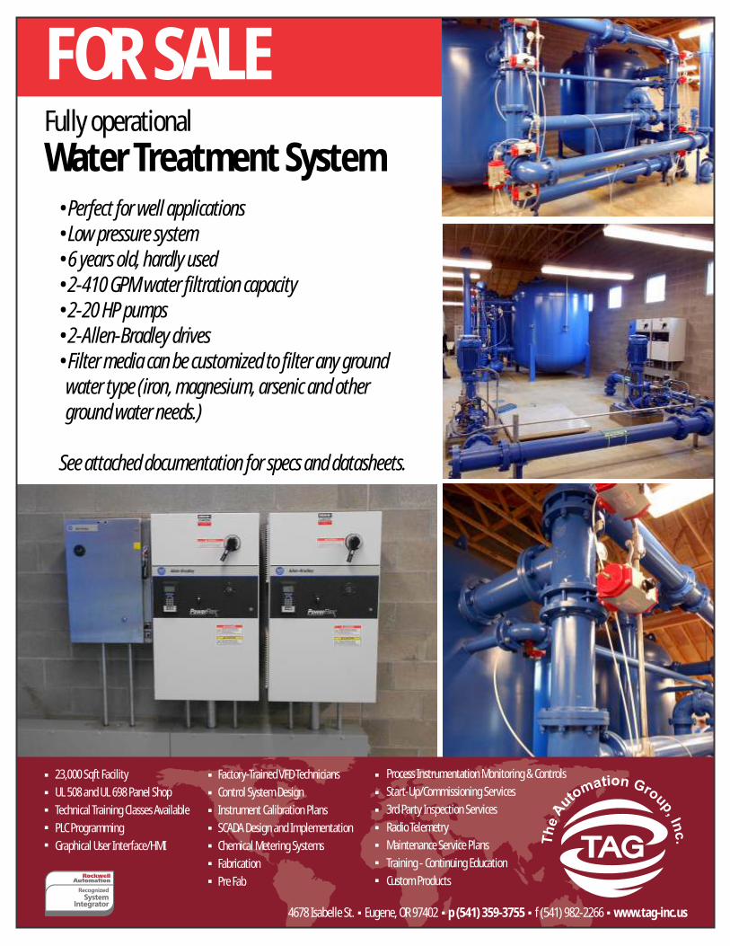
4678 Isabelle St. Eugene, OR 97402 p (541) 359-3755 f (541) 982-2266 www.tag-inc.us 23,000 Sqft Facility UL 508 and UL 698 Panel Shop Technical Training Classes Available PLC Programming Graphical User Interface/HMI Process Instrumentation Monitoring & Controls Start-Up/Commissioning Services 3rd Party Inspection Services Radio Telemetry Maintenance Service Plans Training - Continuing Education Custom Products Factory-Trained VFD Technicians Control System Design Instrument Calibration Plans SCADA Design and Implementation Chemical Metering Systems Fabrication Pre Fab FOR SALE Water Treatment System Fully operational • Perfect for well applications • Low pressure system • 6 years old, hardly used • 2-410 GPM water filtration capacity • 2-20 HP pumps • 2-Allen-Bradley drives • Filter media can be customized to filter any ground water type (iron, magnesium, arsenic and other ground water needs.) See attached documentation for specs and datasheets.
Transcript of Veneta Water Sale Brochure - The Automation Group | PLC ... · ClA-VAl"' Schematic Diagram Item...
4678 Isabelle St. Eugene, OR 97402 p (541) 359-3755 f (541) 982-2266 www.tag-inc.us
23,000 Sqft FacilityUL 508 and UL 698 Panel ShopTechnical Training Classes AvailablePLC ProgrammingGraphical User Interface/HMI
Process Instrumentation Monitoring & ControlsStart-Up/Commissioning Services3rd Party Inspection ServicesRadio TelemetryMaintenance Service PlansTraining - Continuing EducationCustom Products
Factory-Trained VFD TechniciansControl System DesignInstrument Calibration PlansSCADA Design and ImplementationChemical Metering SystemsFabricationPre Fab
FOR SALEWater Treatment SystemFully operational
• Perfect for well applications• Low pressure system• 6 years old, hardly used• 2-410 GPM water filtration capacity• 2-20 HP pumps• 2-Allen-Bradley drives• Filter media can be customized to filter any ground water type (iron, magnesium, arsenic and other ground water needs.)
See attached documentation for specs and datasheets.


DATE: 11/14/2006
EMERSON MOTOR COMPANY 8100 WEST FLORISSANT AVE. P.O. BOX 3946 ·BLDG. K • ST. LOUIS, MO 63136 FAX (314) 553-1101
P.O. NO.; USEM Order/line NO.: 6250 MN
TO:
Model Number: Catalog Number: VSS,WPI 60,230/460V AV,20HP,4P,256VP
F439 NA
REVISIONS; (NONE)
ALL DOCUMENTS HEREIN ARE CONSIDERED CERTIFIED BY US .ELECTRICAL MOTORS.
THANK YOU FOR YOUR ORDER AND THE OPPORTUNITY TO SERVE YOU. Features: HorsePower Enclosure. Poles . . . RPM (Full Load) . Motor Frame Size Phase . . . Frequency. Voltage . . Motor Type Code. Rotor Inertia (LB-FT2) Qty. of Bearings PE (Shaft) Qty. of Bearings SE {OPP) Bearing Number PE (Shaft) Bearing Number SE (OPP}
....: ... �
20 WPI 04
1765 256VP 3
60 460-230
AV 1.99 LB-FT2 1 1 6310-J/C3 6210-2Z-J/C3
• Emerson Motor Company is a division of Emerson Electric Co. The Emerson logo is a trademark and service mark of Emerson Electric Co.
".;:;:::;;:...-'
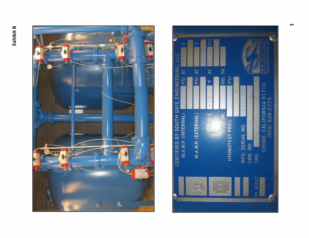
Exhibit A
1

WESTERN HYDRO
[ERR]
--j DD
COL
TPL BL
SL
_l Hydraulic Data Flow (gpm): 250 Pwnp Head (ft): 177.9 TDH (ft): 17&.0 Speed (rpm): 1770 Fluid: Water Temperature (F): 60
.scosity: 1.105 Spec.Grav: I
Version: 2.52
HYDRAULIC ANALYSIS DWT-CATM-MS
7 Stage 6x7CHC
AD: 1.00 AG: 20.31 BD� 12.0 BL: 52.88 CAN: N/A
CL: NIA COL: 30.1" DD: 12.00
DH: 6.75 G: 23.50 H: 21.25 I-II-I: 15.50 J: 0.75 MS 10.25 S: 1.81 SL: 13.00 TPL: 96.0" UG: N/A V: 0.75 W: X:
Y: Z:
fl
J II 0 I A FOUR --rf E10 SP ON "H"
! .{,) r ---EP--- -
PLCS
BC
DISC HEAD Miscellaneous
Thrust At Design: 665 Thrust At Shutoff: 833 Min Water Level(in): 0
Weight Pwnp: 0 Motor: 0 Total: 0
Customer:
Pump Data
Size: Stages: hnpellers: Bowl: BowlS haft: Lineshaft Bearing: LineShaft Matl: LineShaft Type: Column: Column:
Bearing Spacing: Section Length:
Head: Flange (Disch.):
Wet: Lineshaft Coupling: Seal: Strainer: SubBase:
Motor Data Model: Make:
HP: RPM: Type: Efficiency: Frame: Ratchet:
~ 7CHC
7 Bronze
Cast Iron 416SS 1.19"
Rubber 416SS 1"
Open Steel
6" Threaded
A:Cast 611 125#
416SS Packing
Cone None
F-439 u.s
20 1800 vss 90.2
256VP NRR
Date: 11-15-2006
Exhibit A
2

PUMP DATA SHEET Turbine 60 Hz
Company: WESTERN HYDRO
Name:
Date: 11/15/06
Pump: Size: 7CHC (7 stages)
Type: Lineshaft Synch speed: 1800 rpm
Curve: E6407CCPC2
Specific Speeds:
Pump Notes for Standard Sizes:
Customer:
Order No:
Speed: 1770 rpm Dia: 5.0625 in
Ns: 2210
Suction Size-5" Discharge Sizes-5",6"
Vertical Turbine: Bowl size: 7.13 in Max lateral: 0.5 in Thrust K factor: 3.5 lb/lt
Pump Limits for Standard Construction:
Temperature: 120 "F Sphere size: 0.43 in
-- Data Point -
Flow: 250 US gpm
Head: 178 It
Eff: 80.1%
Power: 14 hp
NPSHr: 5.09 It
-Design Curve -
Shutoff Head: 226 ft Shutoff dP: 97.9 psi
Min Flow: - US gpm
BEP: 80.7% eff
@ 228 US gpm
NOL Pwr: 16.2 hp
@ 321 US gpm
--Max Curve -
Max Pwr: 17.9 hp
@ 331 US gpm
Pressure: 415 psi g
Flow Speed US gpm rpm
300 1770
250 1770
200 1770
150 1770
100 1770
Turbine Pump Selection 2004e
Head ft 153
178
196
208
216
· -·· -.- I -·1 I
. . l ·
Search Criteria:
Flow: 250 US gpm
Fluid:
Water SG: 1 Viscosity: 1.105 cP
NPSHa: -It
Motor:
Standard: NEMA
Head: 178 ft
Temperature: 60 "F Vapor pressure: 0.2563 psi a Atm pressure: 14.7 psi a
Size: 20 hp Speed: 1800
Sizing criteria: Max Power on Design Curve
I ·-·
' I I I 1- -- I I
I
I l
Pump Power NPSHr %eff hp ft 74.9 15.5 7.01
80.1 14 5.09
79.9 12.4 3.71
74.8 10.5 2.8
59.3 9.21 2.75
Selected from catalog: Goulds Lineshafl 60Hz Vers: 3.!
Exhibit A
3

ClA-VAl"'
Schematic Diagram Item Description
1 Hytrol (Main Valve) 2 X42N-2 Strainer & Needle Valve 3 CAL Pressure Relief Control
Optional Features Item Description
8 CK2 (Isolation Valve) 0 Check Valves with Isolation Valve F Remote Pilot Sensing H Drain to Atmosphere S CV Speed Control (Opening)
Pressure Relief Service
Service
To provide protection for the system against higll pressure surges wl1en pumps are shut down, this fast opening, slow closing relief valve dissipates the excess pressure.
50-01 _ MODEL __ c_l f,:_ul�l :::ln::I'::'"::'I::P::o2rl)
650-01 (Reduced Internal Por!)
Pressure Relief, Pressure Sustaining Valve
Accurate Pressure Control
Optional Check Feature Fast Opening to Maintain Line Pressure
Slow Closing to Prevents Surges
Completely Automatic Operation
The Cla-Val Model 50-01/650-0i Pressure Relief Valve is a hydraulically operated, pilot-controlled, modulating valve designed to maintain constant upstream pressure within dose limits. This valve can be used tor pressure relief, pressure sustaining, back pressure, or unloading lunctions in a by-pass system. In operation, the valve is actuated by Hne pressure through a pilot control system, opening last to maintain steady line pressure but closing gradually to prevent surges. Operation is completely automatic and pressure seltil/gs may be easily changed. If a check feature is added, and a pressure reversal occurs, the downstream pressure is admitted in the main valve cover chamber, dosing the valve to prevent return flow.
/ "'
The ··o check f<'a!uw on a vert•cally "tnsi«IIE:d o· «nd larger valves musl be ttonzontally oroenled
Pressure Sustaining Service When tnstal!ed in a line between an upper zone and a lower area of heavy demand, the valve acts to maintain desired upstream pressure to prevent "robbing" of the ' upper zone. Water in excess of pressure selling [ J"j flows to area of heavy demand, control is smooth,
------------------------a- na_·;_p_re_ s_s_ur_ e_r_e:.gu_l_al_io_n_i_s.:.p_o_sr_·u_ve_._· _'_;.;.c__:.....;. CUi-VAl
Exhibit A
4

Propeller
MODEL MW500 I MZ5@tt DESCRIPTION
Model MW500 and MZ500 Main Line Propeller Flowmeters are manufactured to comply with the applicable provisions of the American Water Works Association Standard No. C704-02 for propeller type flowmeters. The model MW500 is designed for a maximum continuous working pressure of up to 150 psi and is fitted with AWWA Class D flanges. The model MZ500 is designed for a continuous working pressure of up to 300 psi and is fitted with ANSI 816.5 Class 300 flanges. The impeller and drive assembly are easily removed through the top flange connection. The meter flow tubes are coated with fusion-bonded epoxy for maximum corrosion protection, and integral flow straightening vanes reduce upstream flow turbulence. As with all McCrometer propeller flowmeters, standard features include a magnetically coupled drive, instantaneous flowrate indicator and straight reading, six-digit totalizer.
Impellers are manufactured of high-impact plastic, capable of retaining their shape and accuracy over the life of the meter. Each impeller is individually calibrated at the factory to accommodate the use of any standard McCrometer
' \ \ I I I -1.; . , X ... �- )
'<"'\ '·M·MiifJ!i-BJ " ...._,
APPLICATIONS
The McCrometer Propeller flowmeter comes with a standard instantaneous
flowrate indicator and straight-reading totalizer.
An optional electronic register is also available
Typical face plates.
The McCrometer propeller meter is the most widely used flowmeter for municipal and wastewater treatment applications as well as agricultural and turf irrigation measurement. Typical applications include:
Water and wastewater management
Center pivot systems
Sprinkler irrigation systems
Drip irrigation systems
Golf course and park water management
Gravity turnouts from underground pipelines
Commercial nurseries
i.i"'"�2006 by ivkCrolllctcr/Prin!ed i11 U.S.A.
Lit#24517-20 Rev 1.7/04-06
CONFIGURATION SHEET MAIN LINE FLOWMETER
register. The MW500 and MZ500 can be field-serviced without the need for factory recalibration. Factory lubricated, stainless steel bearings are used to support the impeller shaft. The shielded bearing design limits the entry of materials and fluids into the bearing chamber providing maximum bearing protection.
The instantaneous flowrate indicator is standard and available in gallons per minute, cubic feet per second, liters per second and other units. The register is driven by a flexible steel cable encased within a protective vinyl liner. The register housing protects both the register and cable drive system from moisture while allowing clear reading of the flowrate indicator and totalizer.
INSTALLATION
Standard installation is horizontal mount. If the meter is to b� mounted in the vertical position, please advise the
·factory. A straight run of full pipe the length of five diameters ahead and one diameter behind the meter is the minimum normally recommended.
SHOWN: MODEL MW500
3255 West Stetson Avenue Hemet CA 92545.USA 951-652-6811 I FAX 951-652-2076. Web Site: www.mccrometer.corTI�
Exhibit A
5

MAIN LINE FLOWMETER MODEL MW500 I MZ-500
SPEC/FICA TIONS
PERFORMANCE
ACCURACY: ±2% of reading guaranteed throughout range.
RANGE: See dimensions chart below HEAD LOss: See dimensions chart below MAXIMUM TEMPERATURE: (Standard Construction)
160°F constant PRESSURE RATING Model MWSOO: 150 psi
Moael MZ600. 38&-p.+
MATERIALS
BEARING ASSEMBLY: Impeller shaft is 316 stainless steel. Ball bearings are 440C stainless steel.
MAGNETS: (Permanent type) Cast or sintered Alnico BEARING HOUSING: Brass; Stainless Steel optional REGISTER: An instantaneous flowrate indicator and
six-digit straight-reading totalizer are standard. The register is hermetically sealed within a die cast aluminum case. This protective housing includes a domed acrylic lens and hinged cover with locking hasp.
IMPELLER: Impellers are manufactured of high-impact plastic, retaining their shape and accuracy over the life of the meter. High temperature impeller is optional
OPTIONS
International flange standards available Other than standard laying lengths available Register extensions available
• F01ward/reverse flow measure.ment All stainless steel construction High temperature construction
• "Over Run" bearing asserilbly for higher-thannormal flowrates Electronic propeller meter available in all sizes of this model
• A complete line of flow recording/control instrumentation
• Certified calibration test results
0�.0. 1 r ��� j C D
0 0 ' 0 ° I I I
FLOW=::)
·-
McCROMETER res�s the right/a change design or specifications without notice.
-- --·· L -
" " • • rv'leter and Nominal Pipe Size 2 2 1/2 3 4 6 8 10 12 14 16 18 20 24 30
H
36
.'w'1aximum Flow U.S. GPM 250 250 250 600 1200 1500 1800 2500 3000 4000 5000 6000 8500 12,500 17,000
Minimum Flow. U.S. GPM 40 40 40 50 90 100 125
Approx. Head Loss in Inches 29.50 29.50 29.50 23.00 17.00 6.75 3.75
at Max. Flow MW500
Approx. Shipping Weighl·lbs. 36 36 43 54 115 135 197
B (inches) 3/4 3/4 3/4 3t4 7t8 7/8 1
C (inches) 4 3/4 5 1/2 6 7 1/2 9 1t2 11 3/4 14 1/4
0 {inches) 6 7 7 1/2 9 11 13 1/2 16
H_jinches) 11 3/4 12 1/4 12 1/2 15 1/4 16 1/4 18 1/2 21 3/4
L (inches) 14 16 16 20 22 24 26
No. of Bolts per Flange 4 4 4 8 8 8 12
MZSOO Approx. Shippin� Weight-lbs. 50 55 62 90 145 220 340
B (inches) 3/4 7/8 7/8 7/8 7/8 1 1 1t8
C (inche.!>J 5 5 7/8 6 5/8 7 718 10 5/8 13 15 1/4
D inches 6 1/2 7 1/2 8 1/4 10 12 1/2 15 17 1/2
H (inches) 12 12 1/2 12 7/8 15 3/4 17 19 1/4 22 1/2
l:__{inche� 20 20 20 24 26 28 30
No. of Bolts per Flan�)e 8 8 8 8 12 12 16
Note: Flanges meet ASTM-A-181 specs Larger flowmeters on spec/81 order.
02006 by ivkCromdcr/Printed in U.S.A.
l.il#24517-20 Rev 1.7/04-06
REPRESENTED BY
150 250
2.75 2.00
325 465
1 1 1/8
17 18 3/4
19 21
24 1/4 25 1/4
28 42
12 12
430 650
1 1/4 1 1/4
17 3/4 20 1/4
20 1/2 23
25 26 1/4
32 42
16 20
275 400 475 700 1200 1500
1.75 1.50 1.25 1.00 1.00 1.00
530 744 890 1,293 1450 1650
1 1/8 1 1/4 1 1/4 1 3t8 1 3/8 1 5/8
21 1/4 22 3/4 25 29 1/2 36 42 3/4
23 1/2 25 27 1/2 32 38 3/4 46
28 112 29 1/4 32 1/2 36 3/4 42 3/4 49 1/4
48 54 60 60 60 60
16 16 20 20 28 32
820 1.315 1,508 2,165
1 3/8 1 3t8 1 3/8 1 5t8 ·--22 1/2
25 1/2
29 112
48
20
24 3/4
28
32 3/4
54
24
27 32
30 1/2 36
34 38 3/4
60 60
24 24
3255 Wesl Stetson Avenue Hemet CA 92545 USA 95J.652·6811 I FAX 951 652·3078 Web Site: www.m.ccrome!er.eom ·
Exhibit A
6

Sgecificatian Stleet · ·
Model.: E7000
Feature.\·:
t Industry standard 2-wire 4-20 mA output t Output is linear wilh !lowrate + Compatible witll all McCrometer propeller meters witll a mechanical register t Installation can be accomplished without meter removal from pipe
E7000-0xx
.-\nli-Rcwrsc 0- No I -Yes
l'ulsc Output 0- None I - !Jry Con lac!
+ For meter sizes up to 24" t Signal can travel up to 5000 feet t Additional pulse output and anti-reverse options
E7000 Model: 4�20 mA Output Dry Contact
•
• • •
•
• • •
1 - Open Collector
---7' E7000-000 E7000-001 E7000-002 E7000-010 E7000-011 E7000-012
Open Collector Anti-Reverse
•
• •
• •
Electri('a/ Characteri.Wics: TJ!fl_ical Wiring Di(Jgrams:
.J-2tl mA Oulpul: Operating Temperature:
Supply Voltage:
Temperature Coefficient:
Linearity:
Accuracy:
Maximum Resistive Load:
Reverse Voltage Protection:
!-25 to+ 130 degrees F 16-40 VDC ±1.0% 0.1% 0.5% over the entire range Supply Voltage Dependent* -300V Maximum
Dn lnnlacl Oulpul**: Type: Relay Contact, Norm. Open
Rated Load (AC): 0.5 A at 125 VAC Rated Load (DC): I II at 30 VDC
Max. Operating Current: l A Max. Switching Power: 30 W, 62.5 VA
Contact Closure Duration: 20 milliseconds Max. Clicks per Minute: 10
Optn Colll'I.'IHr Output"*;
Type: NPN Dnrlington, Isolated Isolation Voltage: 5000 V AC
Collector to Emitter Voltage: 40 VDC Maximum Collector Current: 200 mA l\·1aximum
Pulse Output Duration: 20 milliseconds Max. Pulses per Minute: 350
-lise J'nrmula {Supply Vtl!lug,e- J(J) -to 0.02 =--= l''>'l<lxinwm Load(!�)
" lkJ '--'
m,ck v l'7000
4-20 mA Output
Dry Contact OutrHH
Orange " '-"
Blue "
() Jpcn C II () eel or () utpt l l
()range
r * Iliac '--'
• /'lu(..:CIIOII Jliod�: \.,_/
"'* - Tot<1liz..::r output opcnHcs only when power is applied to !he 4-20 mi\ loop.
1\kCwm..:ter rL"scrv..;� 1hL' righ11o thnngc the Sp�titic�tion without notice
© 2005 by McCrorneter, Inc. Printed in U.S.A.
+ Power Supply
- -
- - Instrumentation
+ .:1-20m;\ Input
+ Pu lse
('<Hillier
+ l'ulsc
Counter -
Lit# 24512-00 Rev. 1.5/08-05
Exhibit A
7

I
I
2 480 VOLTS 3PH, 60HZ 3 AC LINES
4
5 +---6
7
31 ' j n
32 I ::r:: 33 to
(/) 34 ' CD ru 35 I
= =
36 = � 37 I ru 38
39 � ru-
40
41
" CBI
�-r-I L2 ----r--
=-{)I
.l2...-o .--L-.. 50 AMP 480V
LINE-PE
")SIS
.,., '"
1071
1081
1091
• " n w
n 1072
c2 1082
c3 1092
� 35A 600V
TO 3-2
AS SHIPPED DOCUMENTS Issue No. -''�'--- Dote: J/30/07 I
::�CHll
EAI
HUMAN INTERFACE MODULE
�(D0C!JOJ !XJGJCDCD@ rnmmms 1!1]Q0�1m DPI PORT 1
1121 1122 1123
POIJER TERMINAL BLOCK I I I I I I I I
I/0 TERMINAL BLOCK TBI : REFER TO PAGE 2 FOR DETAILED INFORMATION
I I I I I
PowerFlex 700 DIGITAL AC DRIVE I I I I I I I
CATALOG NUMBER• 20BD034AOAYNANDO FOR FURTHER DRIVE INFORMATION, REFER TO THE PD'WERFLEX 700 USER MANUAL.
I I I I
DPI PORT 2 1 l',-------"r"o'v<c"R-T"ccR"M"r"N7�"a"L'o"c"K i BRI BR2 +DC DC PE U iVr ::_{V1-'
EA2 HUMAN
INTERFACE MODULE
§!! tli!dB �m
"' IB (D(!)(!J mmm comm Q!Il.@. 0@0J mes�
1251 1252 1253 l,-!\..---!.:.---!":' cHt2 1281 1282 1283
1 -��-$TB12 � I / ���R DATA
= __ VOLTS
- AC __ FLA MTR-PE MOTOR • RPM <BASE>
D
2
3
4
5
6
7
8
9
10
II
12
13
14
15
16
17
18
19
20
22
23
24
25
27 28
29
30
31
32
33
34
1---cc-cc--c=:=:----------------- --------------c-c=c-c-==-:c
ccCCJR�E�F}E�
R�
T�O�M�O! T�O� R�
N�A�McEP�L"A'T �E='
F�O�RCD�A'T�Ac.CCCC� 35 GENERAL NOTES• 4. COIL AND CONTACT CROSS REFERENCING NUt�BERS ADJACENT TO
1. -4-. - BUILDING GROUND TO BE GROUNDED COIL AND UNDER CONTACT INDICATE SHEET AND LINE NUMBERS. BY CUSTOMER.
� '\(y' - SIGNAL COMMON ---J "tJ7 - PO\o/ER EQUIPMENT GROUND 1-3
rh - CHASSIS CONNECTION. SURGE SUPPRESSOR
1,_-3 � -INDICATES LINE NO. 3. � -INDICATES SHEET NO. l, '-- -UNDERSCORED TEXT LINE INDICATES
36
37
38
2. ll: -INDICATES COMPONENTS SUPPLIED BY OTHERS, --�-- - INDICATES 'WIRE SUPPLIED BY OTHERS. A NORMALLY CLOSED CONTACT. 39
3' �@tP 3 L �:��:�:�:: ;::M;NE:LMI��\:D����·UAL i..!LJ II if1 1-# COMPONENTS.
ru ru ru ru UJ _..._ w ru
OFF -PAGE CROSS REFERENCING - NUMBERS ADJACENT TO SOURCE AND DESTINATION SYMBOLS INDICATE SHEET AND LINE NUMBERS.
I I FR,OM. 1--:,24 t-24--- -INDICATES LINE NO. 24. TD i-�4 I I '----INDICATES SHEET No. 1.
w ru
40
41
Exhibit A
8

2
3
5
6
7
8
9
10
II
12
13
14
15
16
17
18
19
20
, ... -22
23
FROM 3-39
3061 'w'30 �
35)
3061
TO 2-31
24 H++-1--i 25
n
FROM OFF 3-39
HAN�UTD 3065 1/0 TERMINAL BLOCK 021 1 ��20� 2� 2:_ ________ �o-----------f__i2� 0� 22�6] DIGITAL INl <STOP>
XDD I 1 T <PARAMETER 361 ; 4) I
AUTO RUN , ! +--mew<__[_) I Q 2041 o-----jf-----o----*-----------+-�2� 0� 22"--'""]DIGITAL IN2 <START> DDX I (31} * (36) <PARAMETER 362 = 5)
I I I $ DIGITAL IN3 I I
L--;mn,O OJ---2� 0�721 ____________________ --+---{�@JDIGITAL IN4 <SPEED SEL. D ODX '- <PARAMETER 364 "' 15)
SS2
AS SHIPPED DOCUMENTS Issue No. --'-01,_ __ Date: 3/30/07
FROM TERMINAL BLOCK TBl 2-13
DIGITAL OUT 1 - N.D. � I
DIGITAL OUT 1 COMMON � 3061 <PARAMETER 380 = 1) I DIGITAL OUT I - N.C. 4, 2351
I I
DIGITAL !JUT 3 - N.D. If 2371 <PARAMETER 388 = 4) I
DIGITAL OUT 2/3 COMMON +s
I :¥1 DIGITAL INS I
�DIGITAL IN6
I �NOT USED
I JOGS :;'a DIGITAL IN COMMON
TO I 2-31
�NOT USED 3151 -}J ANALOG IN I (-)
3161 �ANALOG IN 1 ,., � CUST
{(15) USE o--lc+---"'""--ffl
(16) � 3171 fJ ANALOG IN 2 (-)
CUST {<51 USE r._o-__jC-J--+�31�8� 1�144141 ANALOG IN 2 <+>
<6> II � ANALOG OUT I <-> � ANALOG OUT 1 (+) � ANALOG OUT 2 (�)
�ANALOG OUT 2 (+) [-���������;�;-\ ANALOG IN I I
______________ _) �-���������;;;-: �- ANALOG IN 2 I ______________ _)
lOV PDT REFERENCE
�POT COMMON
tci +lOY POT REfERENCE �--TERMINAL BLOCK TBl
CR6 CR6 CR6 CR6 5i�1 6i�2
CR?
FROM 2-13
3065
I DIGITAL OUT 2 - N.C. � I/O TERMINAL BLOCK
------4>1<}----CR7 CR7 CR7 CR7 RUN si�l 6if-ui-1+2
w
(20)
ru
I
2
3
4
5
'
7
8
9
10
II
12
13
14
15
16
17
18
19
20
� 22
23
24
25
26
27
28
29
30
31
32
33
34
35
36
37
38
39
40
41
Exhibit A
9

I
2
3
4
5
6
7
a
9
10
II
12
13
14
15
16
17
Ia
19
20
"'l a
22 ! l 23
24 ' " 25
!i � 26 I • I " 27
2a p 29 I 30
31 ' l n
32 I I
33 bj V>
34 ' CD ru 35 I
= =
36 0 � 37 I ru 3a
39 "!' •w 40
41
w ru
I
�� :q �� /'\_;;:
li a" �lil rng �� i I� l q !'
�" 'Q-1 O>
� �J,tl.!.� rno
!;: I 'T 0 0 � m
' g �0� .oo ozx L�� �·� oo> ::lr;j :.,�� �n� ' • � • 0 � > r 0 � X
•• s� � G � !ll � � � �
g >
b 0 � � < �
·= � ;; ru �
" .,
�I 306.2
(I) (11) 3061
�)
�) �)
3061
TO 2-1
rn ru rn rn rn rn rn � � 00 � m � • w rn
'" .. "' n
FROM 1-4 �
r��------����-------b���----, 13!5VA L1 I
I F4 F5 I I KLDR-2 480V KLDR-2 I I 600V ':��) 600V I I <HD . ooo' 'ooo <H4> I I � F6
F <��>0 0 0 :2o0�o G ��.2) J� FNM-4
l 2�Y-
AS SHIPPED DOCUMENTS Issue No. 01 Dote: 3/30/07
� 00 �·a; " • w r;; � " � 00
"' ,.
I
2
3
4 (18) (19) 5
CABINET CODLING FAN 6
� 3065 7
a
9
10
II
12
13
14
15
16
17
Ia
19
20
.. 22
23
24
25
26
27
2a
29
30
31
32
33
34
35
36
37
3a 3065 39
TO 2-1 40
41
� m � • w rn -
Exhibit A
10

27 Hi 28
� � 29
� . 30 31 ' l
n 32 I
::r:: 33 tTI
VJ 34
' CD n.J
35 I = = 36 = � 37 I
n.J
38
39 '!' �·
40
41
w ro
ENCLOSURE DIMENSIONS DIMENSIONS ARE IN INCHES [MILLIMETERSl
CONDUIT
ACCESS
I u � � l '
0\) '""-I O> � bt? :r� ron
I 'T 0 0 � ID
i �M-�zz on� LrM MO� o�n �co . �z LfTl� �g� B;;:!S !::u z?-OM� > 0 �-� �M
<� �� � r MM �X �� �g >> n
�
� M
" �
'> s� 6 �
fr u ·=
ro w
22.70 [576.5]
20A3
ro ro 00 �
EM
ro ID '" �
8.75 1 13.75 .,L__r I349.2J
5.28 [134.1J
I [222.3] l
� [25.41 I 0 .41
I
I
I I
[622.1]
22 00 [558.8]
-D �
I
[i] fHJ [J [J [J [J I [J[J[J[J[J[J � - [J • ·� 0
I
I I
I
I
I
� "'
[16,8]
CHASSIS LAYOUT
••
ro ro ro � :g � • w ro
I
DOOR LAYOUT
2
3
= 4
D ������ ����H��
�
5
6
7
DEVICE
1
2 3
4
5
6
7
8
9
10
11
12 13
14
15
DESCRIPTION
NOT USED
NOT USED
NOT USED
NOT USED
NOT USED
NOT USED
NOT USED
HAND/OFF /AUTO S\oiiTCH SS2
NOT USED
NOT USED
NOT USED
NOT USED
NOT USED
NOT USED
HUMAN INTERFACE MODULE EA2
AS SHIPPED DOCUMENTS Issue No. _0!0C1 __ _ Dote: 3/30/07
8
9
10
11
12 13 14
15
16
17
18
19
20
22
23
24
25
26 27 28
29 30 31
32
33
34
35
36
��qg������������==137 f-SYSTEM ENGINEERING NOTES
ENCLOSURE \oiATTS LOSS IS BASED ON 38 THE CARRIER FREQUENCY OF 4KHZ. OPERATION AT HIGHER FREQUENCIES MAY REQUIRE ADDITIONAL COOLING.
SYSTEM IS DESIGNED FOR A MAXIMUM
39
40
AMBIENT TEMPERATURE OF 40 C 41
CONDUIT HUBS MUST TYPE 12 APPROVED
Exhibit A
11

< i i 28 i' � ; 29 I �
30 • 31 ' l
n 32 I
I 33 w
VI 34 ' a:; ru 35 I =
= 3& = � 37 I ru 38
39 � ��
40 z �
41
Q
-- -SYM. EAI-FAN! PT! F4,f5 F& CR& CR7 CBI CH11 CH12 EA! EA2 SS2
� "' ' "'
REPLACEMENT COMPONENTS IJST ----- -- - - --,;::-:8-DESCRIPTION PART NO. MANUFACTURER/PART NO. DRIVE ______ N/A-;-- A B/20IlD034AOAYNANDO ENC, FAN 303127 RITTALISK3326.117 TRANSFORMER 311773 HAMMOND/PT350MQMJ-3 FUSE 149866 LITTLEFUSE/KLDR-2 FUSE 139799 BUSSMANN/FNM-4 RELAY 101215 A-Il/700-HC24A1 RELAY 101215 A-B/700-HC24A1 CRCT BREAKER 304353 CUTLER-HAMMER/HfD3050L REACTOR 162754 A-Il/1321-3R35-Il REACTOR 162754 A-B/1321-3R35-B HIM LCD 305282 A-B/20-HIM-A3 HIM 333185 A-B/20-HIM-C3S SIJITCH N/A A-B/800FP-SM32
AS SHI PED DO UMENTS Issue No. -1'0�1��- te: 3/30/07
I!!�! p D>
� 'i'L 'f;u mn ;:?(.') c;Vl ' ' •• s� D 0 � �
I �--�zz o"" L�� ���
nnn ,oo - zz ki�� ��B ���� �fTl� ��<
�� .� �� , r �R c � �D ,o
> n � � < �
' �
e � !!I ' a" !\!: �
fr !f ==
GENERAL WIRING NOTES J. SEE DRIVE USER MANUAL FOR PLANNING, INSTALLATION,
\./IRING, AND OPERATION INFORMATION. 2. CUSTOMER PD'WER TERMINALS ARE SIZED FOR 75'C COPPER
'WIRE DNL Y PER NEC TABLE 310-16 {75'0. 3. TERMINAL 'WIRE RANGES ARE GIVEN IN THE MINIMUM TO
4.
N 00
MAXIMUM SIZE THAT COMPONENTS VILL ACCEPT. THE END USER IS RESPONSIBLE FOR COMPLETING THE INSTALLATION, \./IRING, AND GROUNDING OF THE DRIVE SYSTEM AND FOR COMPLIANCE TO ANY CODE, NATIONAL, LOCAL DR DTHER'w'ISE FOR PROPER INSTALLATJDN OF THIS DRIVE AND/OR ASSOCIATED EQUIPMENT,
N • ru w N N
n
EXTERNAL INTERCONNECT WIRING REQUIREMENTS
PO\JER SEE DRIVE USER MANUAL FOR CABLE RECOMMENDA liONS AND
RESTRICTIONS. INTERCONNECTION INFORMATION
WiRE--nEVICE-TXPLANATioN--TERM!NAL- - 'i"ERMrNAC--ND. TORQUE WIRE RANGE LC ___ MCPi=-t--iNUiMiNG _____ sEf-DEViCE-i4::-i/OGA--L2 MCP1-3 PO'w'ER LINES L3 MCPI-5 PE LINE -PE LINE -GROUND Tl TB12-1 MOTOR T2 TB12-2 PO'w'ER LINES T3 TB12-3 PE MTR-PE MOTOR-GROUND
35 LB-IN 8-2 GA 50 LB-IN 2-3 GA 45 LB-IN 4-6 GA 40 LB-IN 8 GA 50 LB-IN 2-3 GA 45 LB-IN 4-6 GA 40 LB-IN 8 GA
2
3
4
5
&
7
8
9
10
11
12 CONTROL 1�-==-----�--������------------� 13
SEE DRIVE USER MANUAL FOR CABLE RECOMMENDATIONS AND RESTRICTIONS.
INTERCONNECTION INFORMATION
CR7-5,9 DRIVE RUN NO IHB-16 GA PER CR7-9,l DRIVE RUN NC IHB-16 GA CODE CR7-6,10 DRIVE RUN NO 1118-16 GA CR7-10..2 DRIVE RUN NC 1118 -16 GA -------------------------------------------------------
2041 TB4-31 AUTO RUN 11-30-12 GA PER 2022 Tll4-36 AUTO RUN 1130-12 GA CODE -------------------------------------------------------
SIGNAL SEE DRIVE USER MANUAL fOR CABLE RECOMMENDATIONS AND
RESTRICTIONS. INTERCONNECTION INFORMATION
:; 00 • w N
14
18
19
20
� 23
24
25
27
28
29
30
31
32
35
37
38
39
40
41
Exhibit A
12

Exhibit B
1

Exhibit B
2
Exhi
bit B
1