Vehicle Networks - STI Innsbruck · Vehicle Networks Wireless Local Area Network ... ETP. Avoids...
39
Vehicle Networks Wireless Local Area Network (WLAN) Univ.-Prof. Dr. Thomas Strang, Dipl.-Inform. Matthias Röckl
Transcript of Vehicle Networks - STI Innsbruck · Vehicle Networks Wireless Local Area Network ... ETP. Avoids...

Vehicle Networks
Wireless Local Area Network (WLAN)
Univ.-Prof. Dr. Thomas Strang, Dipl.-Inform. Matthias Röckl

Lect
ure
Veh
icle
Net
wor
ks, T
hom
as S
trang
and
Mat
thia
s R
öckl
, WS
200
8/20
09
Outline
Wireless LANOverviewHistory
IEEE 802.11-1997MAC implementationsPHY implementations
IEEE 802.11 b/g/nIEEE 802.11 a
PHY implementationIEEE 802.11 e
MAC implementation
No. of layer
ISO/OSI ref model
WLAN protocol specification
7 Application
Not specified in theWLAN standards
6 Presentation5 Session4 Transport3 Network
2 Data LinkIEEE 802.11e
IEEE 802.11
1 Physical
IEEE 802.11aIEEE 802.11bIEEE 802.11gIEEE 802.11nIEEE 802.11p

Lect
ure
Veh
icle
Net
wor
ks, T
hom
as S
trang
and
Mat
thia
s R
öckl
, WS
200
8/20
09 Wireless Local Area NetworkIEEE 802.11

Lect
ure
Veh
icle
Net
wor
ks, T
hom
as S
trang
and
Mat
thia
s R
öckl
, WS
200
8/20
09
Wireless LANWLAN standards
WLAN PHY/MAC standardsIEEE 802.11 base standardIEEE 802.11a HDR: 5 GHz, OFDMIEEE 802.11b HDR: 2.4 GHz, CCKIEEE 802.11g HDR: 2.4 GHz, OFDMIEEE 802.11n HDR: MIMOIEEE 802.11p Wireless Access for
Vehicular EnvironmentsWLAN MAC extensions
IEEE 802.11e QoSWLAN security extensions
IEEE 802.11i WPA2Additional standards
IEEE 802.11h European 5 GHz amendment
…
No. of layer
ISO/OSI ref model
WLAN protocol specification
7 Application
Not specified in theWLAN standards
6 Presentation5 Session4 Transport3 Network
2 Data Link
(IEEE 802.2)
IEEE 802.11e
IEEE 802.11
1 Physical
HDR = Higher Data Rate ExtensionMIMO = Multiple Input Multiple OutputQoS = Quality of Service
IEEE 802.11aIEEE 802.11bIEEE 802.11gIEEE 802.11nIEEE 802.11p

Lect
ure
Veh
icle
Net
wor
ks, T
hom
as S
trang
and
Mat
thia
s R
öckl
, WS
200
8/20
09
Wireless LAN History
1987: first standardization activities under IEEE 802.4L (Token Ring)1990: Project Authorization Request (PAR) under IEEE 802.111997: first WLAN standard IEEE 802.11-19972000: Finalization of Higher Data Rate extensions IEEE 802.11a
(54Mbps@5GHz) and IEEE 802.11b ([email protected])2003: Extension of IEEE 802.11a for 5Ghz frequency usage in Europe
(IEEE 802.11h)2003: Finalization of HDR extension IEEE 802.11g ([email protected])2004: Finalization of security extension WPA2 (IEEE 802.11i)2005: QoS extension (IEEE 802.11e)~2009/10: MIMO extension IEEE 802.11n~2009/10: Extension for V2X communication IEEE 802.11p

Lect
ure
Veh
icle
Net
wor
ks, T
hom
as S
trang
and
Mat
thia
s R
öckl
, WS
200
8/20
09 IEEE 802.11-1997

Lect
ure
Veh
icle
Net
wor
ks, T
hom
as S
trang
and
Mat
thia
s R
öckl
, WS
200
8/20
09
IEEE 802.11-1997 Operating Modes
Infrastructure-based networks:Requires central Access Point (AP)AP may be connected to other APs or to the Internet via a Distribution System (DS), e.g. EthernetStations (STA) communicating with an AP set up a Basic Service Set (BSS)STAs of different BSSs communicating via inter-connected APs set up an Extended Basic Service Set (EBSS)
Ad-hoc networks:No central infrastructure requiredStations (STAs) communicate directly to each otherSTAs set up a Independent Basic Service Set (IBSS)
IBSS requires authentication and association procedures

Lect
ure
Veh
icle
Net
wor
ks, T
hom
as S
trang
and
Mat
thia
s R
öckl
, WS
200
8/20
09
IEEE 802.11-1997 Layers
Logical Link Control (LLC):based on IEEE 802.2 (identical for the whole 802.x family)Medium Access Control (MAC):common basic MAC for all IEEE 802.11 WLAN systemsPhysical Layer Convergence Protocol (PLCP):unique access point to PHY layer (PHY-SAP) independent of transmission mediumPhysical Medium Dependent (PMD):PHY layer implementation dependent on transmission mediumManagement Plane:Layer management functions
No. of layer
ISO/OSI ref model Data Plane Management Plane
2bData Link
Logical Link Control(LLC) S
tation Managem
ent
2a Medium Access Control(MAC)
MACManagement
1b
Physical
Physical Layer Convergence Protocol
(PLCP) PHY Management
1aPhysical Medium
Dependent(PMD)
MAC-PHY mappingSynchronizationCarrier sense signalingClear Channel Assessment (CCA)
Channel CodingAnalog & Digital Modulation
Multiple AccessPrioritization

Lect
ure
Veh
icle
Net
wor
ks, T
hom
as S
trang
and
Mat
thia
s R
öckl
, WS
200
8/20
09 IEEE 802.11-1997MAC

Lect
ure
Veh
icle
Net
wor
ks, T
hom
as S
trang
and
Mat
thia
s R
öckl
, WS
200
8/20
09
DFWMAC
IEEE 802.11-1997 Medium Access Control
Distributed Foundation Wireless Medium Access Control (DFWMAC)Distributed Coordination Function (DCF):
CSMA (mandatory)CSMA/CA with RTS/CTS (optional)
Point Coordination Function (PCF):Polling (optional)
Distributed Coordination Function(DCF)
Point Coordination Function
(PCF)
CSMA RTS/CTS

Lect
ure
Veh
icle
Net
wor
ks, T
hom
as S
trang
and
Mat
thia
s R
öckl
, WS
200
8/20
09
IEEE 802.11-1997 Medium Access Control
DFWMAC uses time delays to prioritize messages and avoid collisionsEvery message is deferred according to a distributed time delay schemeTwo types of delays:
Fixed delay time: Prioritization of more important messagesFixed Inter-Frame Spaces (IFS) according to message typeHigh priority messages have short delay timesLow priority messages have longer delay times
Random delay time: Collision avoidanceBased on traffic adaptive backoff mechanismIn high traffic conditions delay time tend to be longerIn low traffic conditions delay time tend to be shorterRandom delay times are zero in case of only one node being allowed to send (e.g. the recipient of the last message)

Lect
ure
Veh
icle
Net
wor
ks, T
hom
as S
trang
and
Mat
thia
s R
öckl
, WS
200
8/20
09
Channel busy
IEEE 802.11-1997 MAC: CSMA
1. If a node wants to access the medium, it listens on the channel at least for the DCF Inter-Frame Space (DIFS)
2. If the channel remains idle for the whole DIFS, the node immediately accesses the channel
short waiting times in low traffic conditions3. If the channel gets busy, the node defers its operation
until the channel gets idle and again listens on the channel for DIFS
4. If the channel remains idle, it starts its backoff counter and decrements it with every empty slot
5. If the channel gets busy, its freezes the backoff algorithm for the channel busy time
6. If the backoff counter eventually reaches zero the node accesses the channel
Sender A
Sender B
Sender C
8 7 6 5
DIFS
DIFS 4 3 2 1
DIFS
Channel busy DIFS
Data to transmit
Channel idle for DIFS
Transmit
yes
Wait until channel becomes idle
no
Channel idle for DIFS
no
(Re)start Backoff
yes
Ch. idle for Backoff time
yes no
Channel busy
DIFS

Lect
ure
Veh
icle
Net
wor
ks, T
hom
as S
trang
and
Mat
thia
s R
öckl
, WS
200
8/20
09
IEEE 802.11-1997 MAC: CSMA
Acknowledgements (ACKs) are used to detect collisions in unicast communicationACKs require a timely deliveryIn order to prioritize ACKs, nodes that compete for the channel to send an ACK only have to wait for a shorter duration, the Short Inter-Frame Space (SIFS) < DIFS
Sender A
Sender B
Sender C
DIFS
ACK
2 1
SIFS
DIFS DIFS
DIFS
Data to B

Lect
ure
Veh
icle
Net
wor
ks, T
hom
as S
trang
and
Mat
thia
s R
öckl
, WS
200
8/20
09
IEEE 802.11-1997 MAC: CSMA/CA
Avoidance of Hidden-Terminal-Problem (HTP) and Exposed-Terminal-Problem (ETP) by explicit channel reservation with RTS/CTS messagesRTS and CTS include channel reservation timeEvery node stores the channel reservation time in its Network Allocation Vector (NAV)
Sender A
Sender B
NAV of sender C
DIFS
CTSS
IFS
RTSS
IFS Data to B
SIFS ACK
NAV of sender DChannel
Reserved
Channel reserved
Free to transmit
B
CA
D
Avoids ETP
Avoids HTP
1. To send an RTS message, initiator has to use CSMA with DIFS2. Responder acknowledges the RTS with a CTS after SIFS3. Initiator is allowed to transmit after waiting another SIFS

Lect
ure
Veh
icle
Net
wor
ks, T
hom
as S
trang
and
Mat
thia
s R
öckl
, WS
200
8/20
09
IEEE 802.11-1997 MAC: Point Coordination Function
Applicable in infrastructure-based mode onlyCentral coordinated MAC: Polling by access point acting as Point Coordinator (PC)Periodic super frames consisting of a Contention Free Period (CFP) and a Contention Period (CP)CFP is introduced by the PC at the beginning of each super frame with a PCF Inter-Frame Space (PIFS)SIFS < PIFS < DIFS ( PCF has higher priority than DCF)If a polled station does not reply, the PC polls the next station after waiting PIFS
Point Coordinator
Station A
Station C
PIFS
Data
SIFS
SIFS
Poll A
Super frameContention Free Period Contention
Period
SIFS PIFS Poll CPoll B
Data
Super frame

Lect
ure
Veh
icle
Net
wor
ks, T
hom
as S
trang
and
Mat
thia
s R
öckl
, WS
200
8/20
09
IEEE 802.11-1997Backoff algorithm
Contention Window (CW) is exponentially increased in case of collisionsCW = x2 – 1, x=x+1 in case of collisionBackoff time = Random(CW) * SlotTime
Random(CW): Random number from the interval [0;CW]SlotTime = PHY layer dependent
FHSS: 50 μsDSSS: 20 μs
CW is reset in case of successful transmission (detected by ACKs)Upper bounds (CWmax) and lower bounds (CWmin) for CW depend on PHY layer:
FHSS: CWmin = 15, CWmax = 1023DSSS: CWmin = 31, CWmax = 1023
CW
1524
35
48
1023
….CWmin
CWmax
Initial Attempt (no backoff)
First RetransmitSecond Retransmit
Third Retransmit

Lect
ure
Veh
icle
Net
wor
ks, T
hom
as S
trang
and
Mat
thia
s R
öckl
, WS
200
8/20
09
IEEE 802.11-1997 MAC frame structure
Header Payload TrailerFrame Control Duration Address 1 Address 2 Address 3 Sequence
Control Address 4 Frame Body FCS
Byte 2 2 6 6 6 2 6 0-2312 4
Prot. Vers. Type Sub-
typeTo DS
From DS
More Frag. Retry Pwr
MgmtMore Data WEP Or-
derBit 2 2 4 1 1 1 1 1 1 1 1
To DS
From DS Addr. 1 Addr. 2 Addr. 3 Addr. 4
0 0 physical Recv.
physical Sender BSSID -
0 1 physical Recv. BSSID logical
Sender -
1 0 BSSID physical Sender
logical Recv. -
1 1 physical Recv.
physical Sender
logical Recv.
logical Sender
1
2
3
4

Lect
ure
Veh
icle
Net
wor
ks, T
hom
as S
trang
and
Mat
thia
s R
öckl
, WS
200
8/20
09 IEEE 802.11-1997PHY

Lect
ure
Veh
icle
Net
wor
ks, T
hom
as S
trang
and
Mat
thia
s R
öckl
, WS
200
8/20
09
IEEE 802.11-1997Physical Layer
3 basic implementations:
Frequency Hopping Spread Spectrum (FHSS)2.4 GHz ISM band (EU: 100mW EIRP, US: 1W EIRP)Frequency Spreading
Direct Sequence Spread Spectrum (DSSS)2.4 GHz ISM band (EU: 100mW EIRP, US: 1W EIRP)Code Spreading
Diffused Infrared (DFIR)Infrared: 850nm – 900nmNot used in practice

Lect
ure
Veh
icle
Net
wor
ks, T
hom
as S
trang
and
Mat
thia
s R
öckl
, WS
200
8/20
09
Frequency spreadingISM band is separated in 79 non-overlapping channels with bandwidth of 1 MHz
Channel is changed with 2.5 Hz ( channel dwell period = 400 ms) according to a pseudo-random hopping sequence (e.g. c1,c7,c25,c55,c37,c61, c1,c7,c25…)Next channel has to be at least 6 MHz apartChannel width = 1 MHzSymbol rate = 1 Msps (million symbols per second)Modulation:
2-Level Gaussian FSK 1 Mbps data rate4-Level Gaussian FSK 2 Mbps data rate
IEEE 802.11-1997FHSS: PMD
c1
fc7 c25 c55c37 c61
…Channel
Frequency c79
1 2 3 4 5 6 77 78 79

Lect
ure
Veh
icle
Net
wor
ks, T
hom
as S
trang
and
Mat
thia
s R
öckl
, WS
200
8/20
09
IEEE 802.11-1997FHSS: PLCP frame
Preamble (1 Mbps):SYNC (Synchronisation): alternating “0” and “1”SFD (Start of Frame Delimiter): 0000 1100 1011 1101
Header (1 Mbps):PLW (Packet Length Width): Length of SDU in bitsPSF (Packet Signaling Field): Data rate in 0.5 Mbps steps starting with 1 MbpsCyclic Redundancy Check (CRC): G(x) = x16 + x12 + x5 + 1
Data (1-2 Mbps)
Preamble Header Data
SYNC SFD PLW PSF CRC MAC-PDUBit 80 16 12 4 16 <=4095 Byte
Data rate = 1 Mbps 1-2 Mbps
Lect
ure
Veh
icle
Net
wor
ks, T
hom
as S
trang
and
Mat
thia
s R
öckl
, WS
200
8/20
09
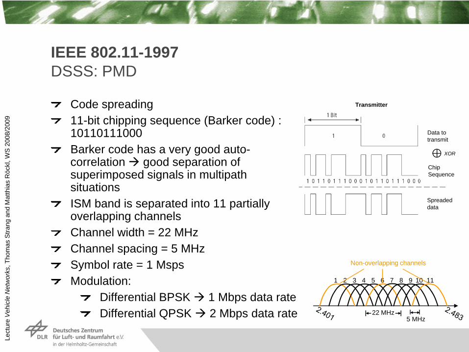
IEEE 802.11-1997DSSS: PMD
Code spreading11-bit chipping sequence (Barker code) : 10110111000Barker code has a very good auto-correlation good separation of superimposed signals in multipath situationsISM band is separated into 11 partially overlapping channelsChannel width = 22 MHzChannel spacing = 5 MHzSymbol rate = 1 Msps Modulation:
Differential BPSK 1 Mbps data rateDifferential QPSK 2 Mbps data rate
Data to transmit
ChipSequence
Spreadeddata
Transmitter
XOR
Non-overlapping channels
22 MHz5 MHz
1 2 3 4 5 6 7 8 9 10 11

Lect
ure
Veh
icle
Net
wor
ks, T
hom
as S
trang
and
Mat
thia
s R
öckl
, WS
200
8/20
09
IEEE 802.11-1997DSSS: PLCP frame
Preamble (1 Mbps):SYNC (Synchronisation): alternating “0” and “1”SFD (Start of Frame Delimiter): 1111 0011 1010 0000
Header (1 Mbps):Signal: Data rate in 0.1 Mbps stepsService: reservedLength: Length of SDU in microsecondsCyclic Redundancy Check (CRC): G(x) = x16 + x12 + x5 + 1
Data (1-2 Mbps)
Preamble Header Data
SYNC SFD Signal Service Length CRC MAC-PDUBit 128 16 8 8 16 16 <=4095 Byte
Data rate = 1 Mbps 1-2 Mbps

Lect
ure
Veh
icle
Net
wor
ks, T
hom
as S
trang
and
Mat
thia
s R
öckl
, WS
200
8/20
09
IEEE 802.11-1997Comparison FHSS vs. DSSS
FHSS DSSSSpreading Frequency Code
Modulation FSK PSK
Signal-to-Noise Ratio (SNR) 18 dB 12 dB
Frequency band 2.402 – 2.480 GHz 2.401 – 2.483 GHz
Bandwidth 79 MHz(Short term: 1 MHz for a single hop)
22 MHz(for a single sub-band)
Data rates 1 Mbps (mandatory)2 Mbps (optional)
1 Mbps (mandatory)2 Mbps (optional)
Slot time 50 μs 20 μs
SIFS 28 μs 10 μs
Preamble length 96 bits (96 μs) 144 bits (144 μs)
Header length 32 bits (32 μs) 48 bits (48 μs)

Lect
ure
Veh
icle
Net
wor
ks, T
hom
as S
trang
and
Mat
thia
s R
öckl
, WS
200
8/20
09
IEEE 802.11b/g/n

Lect
ure
Veh
icle
Net
wor
ks, T
hom
as S
trang
and
Mat
thia
s R
öckl
, WS
200
8/20
09
IEEE 802.11b/g/nIEEE 802.11b
IEEE 802.11b extends IEEE 802.11 DSSS with two additional PMDs:5.5 Mbps: QPSK symbols spread by 8-chip Complementary Code Keying (CCK) encoding 2 bits11 Mbps: QPSK symbols spread by 8-chip Complementary Code Keying (CCK) encoding 6 bits
Data rate
Code length Modu-lation
Symbol rate
Bits/Symbol
1 Mbps 11(Barker-Code)
BPSK 1 Msps 1
2 Mbps 11 (Barker-Code)
QPSK 1 Msps 2
5.5 Mbps 8 (CCK)
QPSK 1.375 Msps
4(2+2)
11 Mbps 8 (CCK)
QPSK 1.375 Msps
8(2+6)

Lect
ure
Veh
icle
Net
wor
ks, T
hom
as S
trang
and
Mat
thia
s R
öckl
, WS
200
8/20
09
IEEE 802.11b/g/nIEEE 802.11g
2.4 GHz ISM bandModulation: OFDM (similar to IEEE 802.11a)Data rates: 6, 9, 12, 18, 24, 36, 48, 54 Mbps (OFDM)
+ 1, 2, 5.5, 11 Mbps (CCK)Backward compatible to IEEE 802.11b

Lect
ure
Veh
icle
Net
wor
ks, T
hom
as S
trang
and
Mat
thia
s R
öckl
, WS
200
8/20
09
IEEE 802.11b/g/nIEEE 802.11n
Designed for applications with very high data rate requirements (e.g. home entertainment, harddisk streaming, gaming)Several antennas used for parallel transmission:Multiple Input / Multiple Output (MIMO)e.g. 2x2 (= 2 transmitting antennas, 2 receiving antennas)Max. data rate: ~600 MbpsFrequency band: 2.4 GHz / 5 GHzOFDM modulation with 20/40 MHz channels and 4 spatial streams (4x4)Additional MAC enhancements for faster transmission

Lect
ure
Veh
icle
Net
wor
ks, T
hom
as S
trang
and
Mat
thia
s R
öckl
, WS
200
8/20
09
IEEE 802.11a

Lect
ure
Veh
icle
Net
wor
ks, T
hom
as S
trang
and
Mat
thia
s R
öckl
, WS
200
8/20
09R
EC
AP
IEEE 802.11aPHY: OFDM
Each sub-carrier can have an individual modulation (e.g. QPSK or QAM)Guardband (aka Guardinterval) per symbol reduce Inter-Symbol InterferenceSynchronization by pilot signals in specific sub-carriersChannel estimation with training symbols
Advantages of OFDM:High spectrum efficiencyResistance against narrow-band interferers and signal distortionsResistance against multipath errors
Orthogonalsub-carriers
f

Lect
ure
Veh
icle
Net
wor
ks, T
hom
as S
trang
and
Mat
thia
s R
öckl
, WS
200
8/20
09
IEEE 802.11aPHY
IEEE 802.11a uses OFDM with 64 sub-carriers:48 data sub-carriers4 pilot sub-carriers12 guard sub-carriers (at spectrum edges)
Channel coding:Scrambling w/ LFSR and its G(x) = x7 + x4 + 1Forward Error Correction:Convolution Coder (2,1,7), (4,3,7), (3,2,7)Inter-carrier interleaving:Block interleaver (12x16) or (18x16)
Data rates: 6-54 MbpsSymbol rate: 250 kspsChannel bandwidth: 20 MHzSub-carrier spacing: 312.5 kHz (= 20 MHz/64)Symbol duration: 4 μsGuard period between symbols: 0.8 μs
250 ksps * 48 sub-carriers * 6 coded bits/sub-carrier * ¾ coding rate = 54 Mbps

Lect
ure
Veh
icle
Net
wor
ks, T
hom
as S
trang
and
Mat
thia
s R
öckl
, WS
200
8/20
09
IEEE 802.11aPhysical Layer Convergence Protocol (PLCP) frame
Preamble:10 short training symbols t1-t10: used for timing and coarse frequency synchronization2 long training symbols T1-T2: used for channel estimation and fine frequency acquisition
t1 t2 t3 t4 t5 t6 t7 t8 t9 t10 T1 T2

Lect
ure
Veh
icle
Net
wor
ks, T
hom
as S
trang
and
Mat
thia
s R
öckl
, WS
200
8/20
09
IEEE 802.11aFrequency band
IEEE 802.11a is designed for the 5 GHz bandHigher frequency higher signal attenuation (see unit “wireless communication basics”)
IEEE 802.11a needs higher power output to achieve the same range as in the 2.4 GHz bandAdvantages of 5 GHz:
Less crowdedless co-channel interference and adjacent channel interference
Higher bandwidth more channels available (19 ch. in Europe)High power usage allowed in certain areas and frequencies

Lect
ure
Veh
icle
Net
wor
ks, T
hom
as S
trang
and
Mat
thia
s R
öckl
, WS
200
8/20
09
IEEE 802.11aEuropean regulation
In Europe the 5 GHz band was exclusively assigned to HIPERLAN/2, satellite and radar systems
IEEE 802.11a was not allowed in Europe till 2005Additional functionality required to use IEEE 802.11a in Europe is defined in IEEE 802.11h:
Dynamic Frequency Selection (DFS)Avoidance of interference with radar systemsStation has to switch the channel, if it detects an active radar systemIn infrastructure-based mode, AP decides on the channel switch
Transmit Power Control (TPC)Reduction of interference with satellite systems (and possibly other systems in the same frequency band)Station has to reduce the transmit power, if it detects an active satellite communication

Lect
ure
Veh
icle
Net
wor
ks, T
hom
as S
trang
and
Mat
thia
s R
öckl
, WS
200
8/20
09
IEEE 802.11aFrequency bandsRegulatory
domainFrequency
BandChannel Number Frequency Max. output power
(CEPT)Indoor/
Outdoor
United States (FCC)Europe (CEPT)
U-NII lower band
5.150-5.250 GHz
36404448
5.180 GHz5.200 GHz5.220 GHz5.240 GHz
TPC No TPC
OnlyIndoor
DFS200 mW(23 dBm)
No DFS60 mW
(18 dBm)30 mW
(15 dBm)
United States (FCC)Europe (CEPT)
U-NII middle band
5.250-5.350 GHz
52566064
5.260 GHz5.280 GHz5.300 GHz5.320 GHz
With TPC:200 mW (23 dBm)
Without TPC:100 mW (20 dBm)
OnlyIndoor
Europe (CEPT) 5.470-5.725 GHz
100104108112116120124128132136140
5.500 GHz5.520 GHz5.540 GHz5.560 GHz5.580 GHz5.600 GHz5.620 GHz5.640 GHz5.660 GHz5.680 GHz5.700 GHz
With TPC:1 W (30 dBm)
Without TPC:500 W (27 dBm)
Indoor&
Outdoor
DFS – Dynamic Frequency SelectionTPC – Transmit Power Control

Lect
ure
Veh
icle
Net
wor
ks, T
hom
as S
trang
and
Mat
thia
s R
öckl
, WS
200
8/20
09
WLAN IEEE 802.11Summary of basic standards
Standard Standard approved
Spectrum Max. data rate
Modulation
IEEE 801.11 1997 2.4 GHz+ 850 nm
2 Mbps FHSS/DSSS
IEEE 801.11a 1999 5 GHz 54 Mbps OFDM
IEEE 801.11b 1999 2.4 GHz 11 Mbps DSSS (CCK)
IEEE 801.11g 2003 2.4 GHz 54 Mbps OFDM+CCK
IEEE 801.11n ~2009/2010 2.4/5 GHz ~600 Mbps OFDM + MIMO
IEEE 801.11p ~2009/2010 5.9 GHz 27 Mbps OFDM

Lect
ure
Veh
icle
Net
wor
ks, T
hom
as S
trang
and
Mat
thia
s R
öckl
, WS
200
8/20
09
IEEE 802.11e

Lect
ure
Veh
icle
Net
wor
ks, T
hom
as S
trang
and
Mat
thia
s R
öckl
, WS
200
8/20
09
IEEE 802.11eQuality of Service (QoS)
Standard IEEE 802.11 does not allow to prioritize different kinds of data packetsIEEE 802.11e defines a MAC enhancement to support QoSStandard IEEE 802.11 DCF/PCF extended by Hybrid Coordination Function (HCF):
Enhanced Distributed Channel Access (EDCA)DCF with additional priority classesHCF Controlled Channel Access (HCCA)PCF with additional priority classes
Distributed Coordination Function(DCF)CSMA RTS/CTS
HCCAEDCA
Point Coordination Function
(PCF)
HCF

Lect
ure
Veh
icle
Net
wor
ks, T
hom
as S
trang
and
Mat
thia
s R
öckl
, WS
200
8/20
09
IEEE 802.11eAccess Categories
4 different traffic categories (Access Categories):AC0: Background trafficAC1: Best-Effort trafficAC2: Video trafficAC3: Voice traffic
Two control mechanisms:IFS: Arbitrate Inter-Frame Space (AIFS)with different lengths instead of a fixed-length DIFSContention Window: Different values for CWmin and CWmax
High priority traffic has a higher probability to get access to the medium first
AC0 AC1 AC2 AC3
Virtual Collision Handler
Transmission Attempt
Backoff
AIFS[0]
CW[0]
Backoff
AIFS[1]
CW[1]
Backoff
AIFS[2]
CW[2]
Backoff
AIFS[3]
CW[3]