VDSL2 and G.fast Circuit Protection · VDSL2 and G.fast Circuit Protection. Purpose Discuss recent...
56
Presented by: Tim Howell Staff FAE – Communications Market Segment Bourns, Inc. VDSL2 and G.fast Circuit Protection
Transcript of VDSL2 and G.fast Circuit Protection · VDSL2 and G.fast Circuit Protection. Purpose Discuss recent...
Presented by: Tim Howell
Staff FAE – Communications Market Segment Bourns, Inc.
VDSL2 and G.fast Circuit Protection
Purpose Discuss recent improvements to circuit protection for VDSL2 line drivers, and the results of applying the same solution to a G.fast application This presentation discusses the results of internal testing to select ITU-T K series recommendations
2
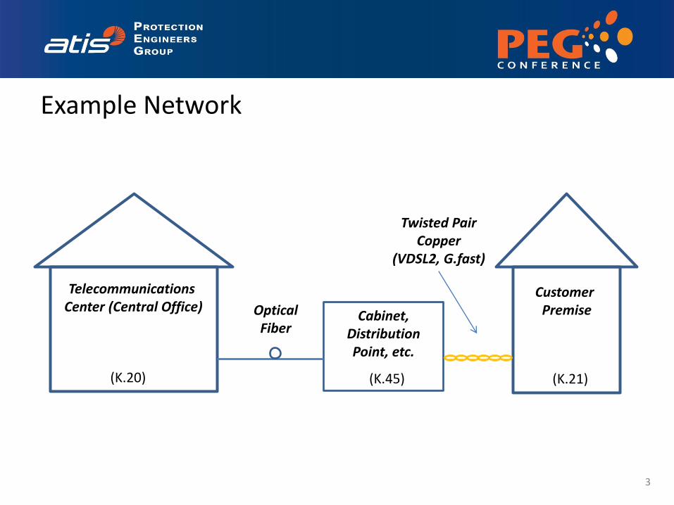
Customer Premise
Telecommunications Center (Central Office)
Cabinet, Distribution Point, etc.
Optical Fiber
Twisted Pair Copper
(VDSL2, G.fast)
(K.20) (K.45) (K.21)
Example Network
3
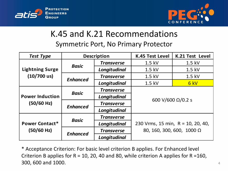
K.45 and K.21 Recommendations Symmetric Port, No Primary Protector
* Acceptance Criterion: For basic level criterion B applies. For Enhanced level Criterion B applies for R = 10, 20, 40 and 80, while criterion A applies for R =160, 300, 600 and 1000. 4
Test Type K.45 Test Level K.21 Test Level
Transverse 1.5 kV 1.5 kV
Longitudinal 1.5 kV 1.5 kV
Transverse 1.5 kV 1.5 kV
Longitudinal 1.5 kV 6 kV
Transverse
Longitudinal
Transverse
Longitudinal
Transverse
Longitudinal
Transverse
Longitudinal
600 V/600 Ω/0.2 sPower Induction
(50/60 Hz)
Basic
Enhanced
Power Contact*
(50/60 Hz)
Basic230 Vrms, 15 min, R = 10, 20, 40,
80, 160, 300, 600, 1000 ΩEnhanced
Description
Lightning Surge
(10/700 us)
Basic
Enhanced
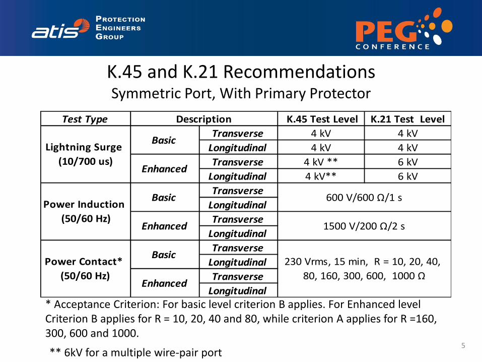
K.45 and K.21 Recommendations Symmetric Port, With Primary Protector
* Acceptance Criterion: For basic level criterion B applies. For Enhanced level Criterion B applies for R = 10, 20, 40 and 80, while criterion A applies for R =160, 300, 600 and 1000.
** 6kV for a multiple wire-pair port 5
Test Type K.45 Test Level K.21 Test Level
Transverse 4 kV 4 kV
Longitudinal 4 kV 4 kV
Transverse 4 kV ** 6 kV
Longitudinal 4 kV** 6 kV
Transverse
Longitudinal
Transverse
Longitudinal
Transverse
Longitudinal
Transverse
Longitudinal
600 V/600 Ω/1 s
Enhanced 1500 V/200 Ω/2 s
Power Contact*
(50/60 Hz)
Basic230 Vrms, 15 min, R = 10, 20, 40,
80, 160, 300, 600, 1000 ΩEnhanced
Description
Lightning Surge
(10/700 us)
Basic
Enhanced
Power Induction
(50/60 Hz)
Basic
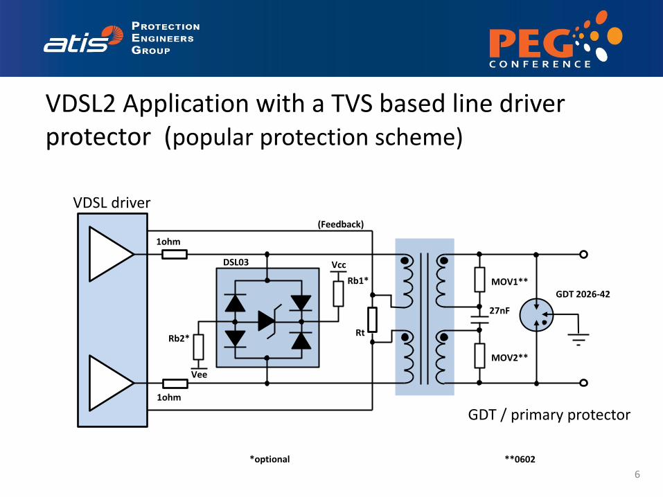
DSL03
GDT 2026-42
1ohm
1ohm
Rt
27nF
GDT / primary protector
VDSL2 Application with a TVS based line driver protector (popular protection scheme)
MOV2**
MOV1**
(Feedback)
Rb1*
Rb2*
Vcc
Vee
*optional **0602
VDSL driver
6
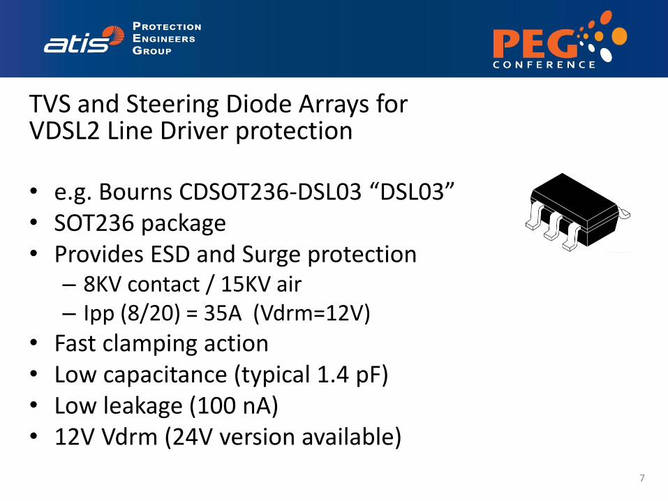
TVS and Steering Diode Arrays for VDSL2 Line Driver protection
• e.g. Bourns CDSOT236-DSL03 “DSL03” • SOT236 package • Provides ESD and Surge protection
– 8KV contact / 15KV air – Ipp (8/20) = 35A (Vdrm=12V)
• Fast clamping action • Low capacitance (typical 1.4 pF) • Low leakage (100 nA) • 12V Vdrm (24V version available)
7
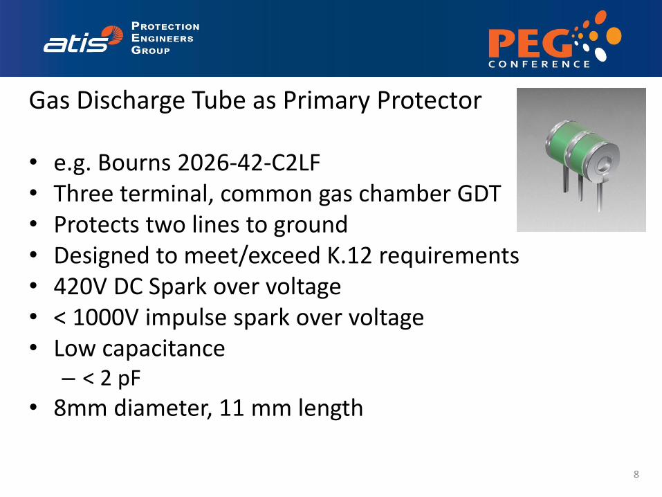
Gas Discharge Tube as Primary Protector
• e.g. Bourns 2026-42-C2LF • Three terminal, common gas chamber GDT • Protects two lines to ground • Designed to meet/exceed K.12 requirements • 420V DC Spark over voltage • < 1000V impulse spark over voltage • Low capacitance
– < 2 pF
• 8mm diameter, 11 mm length
8
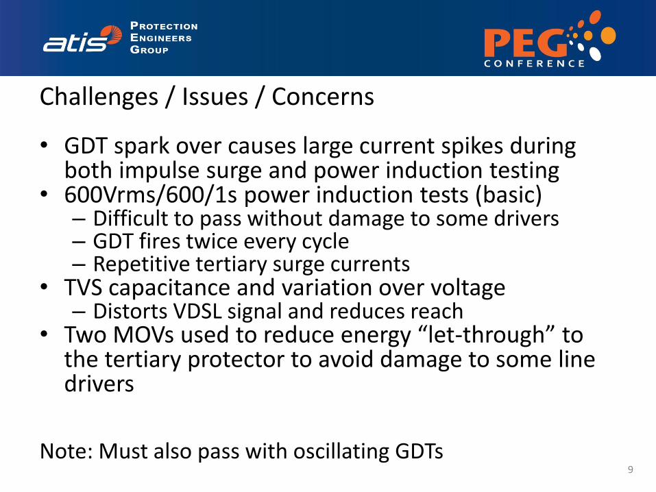
Challenges / Issues / Concerns
• GDT spark over causes large current spikes during both impulse surge and power induction testing
• 600Vrms/600/1s power induction tests (basic) – Difficult to pass without damage to some drivers – GDT fires twice every cycle – Repetitive tertiary surge currents
• TVS capacitance and variation over voltage – Distorts VDSL signal and reduces reach
• Two MOVs used to reduce energy “let-through” to the tertiary protector to avoid damage to some line drivers
Note: Must also pass with oscillating GDTs
9
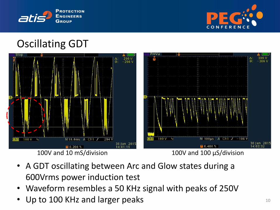
Oscillating GDT
10
• A GDT oscillating between Arc and Glow states during a 600Vrms power induction test
• Waveform resembles a 50 KHz signal with peaks of 250V • Up to 100 KHz and larger peaks
100V and 10 mS/division 100V and 100 µS/division
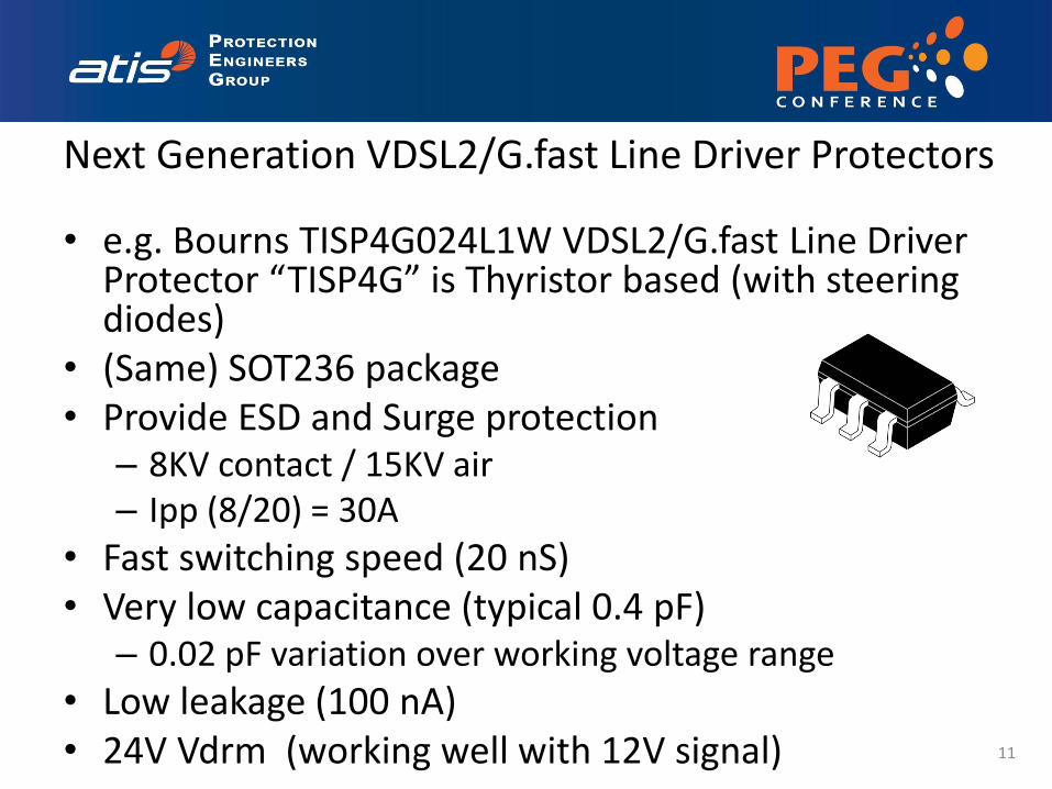
Next Generation VDSL2/G.fast Line Driver Protectors
• e.g. Bourns TISP4G024L1W VDSL2/G.fast Line Driver Protector “TISP4G” is Thyristor based (with steering diodes)
• (Same) SOT236 package • Provide ESD and Surge protection
– 8KV contact / 15KV air – Ipp (8/20) = 30A
• Fast switching speed (20 nS) • Very low capacitance (typical 0.4 pF)
– 0.02 pF variation over working voltage range
• Low leakage (100 nA) • 24V Vdrm (working well with 12V signal) 11
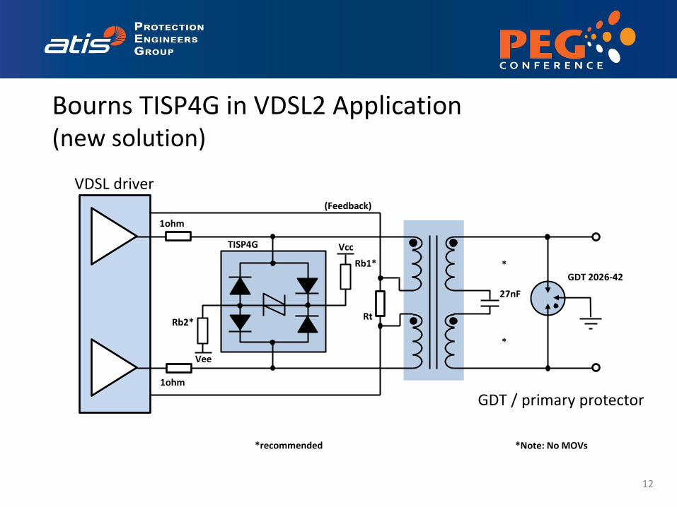
TISP4G
1ohm
1ohm
Bourns TISP4G in VDSL2 Application (new solution)
GDT 2026-42
GDT / primary protector
*Note: No MOVs
Rt
(Feedback)
Rb1*
Rb2*
Vcc
Vee
VDSL driver
27nF
*recommended
*
*
12
DSL03
GDT 2026-42
1ohm
1ohm
Rt
27nF
GDT / primary protector
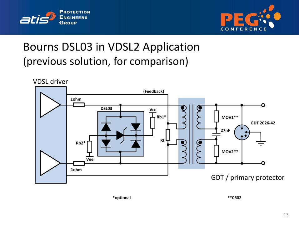
Bourns DSL03 in VDSL2 Application (previous solution, for comparison)
MOV2**
MOV1**
(Feedback)
Rb1*
Rb2*
Vcc
Vee
*optional **0602
VDSL driver
13
14
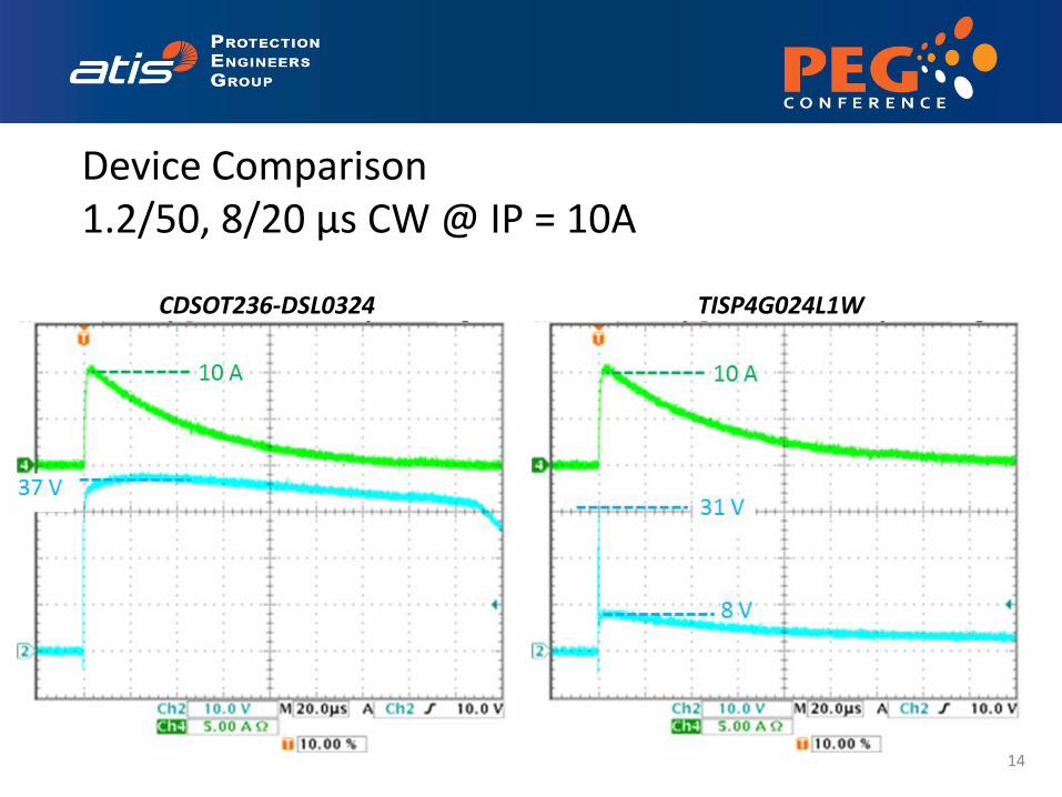
37 V
10 A
31 V
10 A
8 V
CDSOT236-DSL0324 TISP4G024L1W
Device Comparison 1.2/50, 8/20 µs CW @ IP = 10A
15
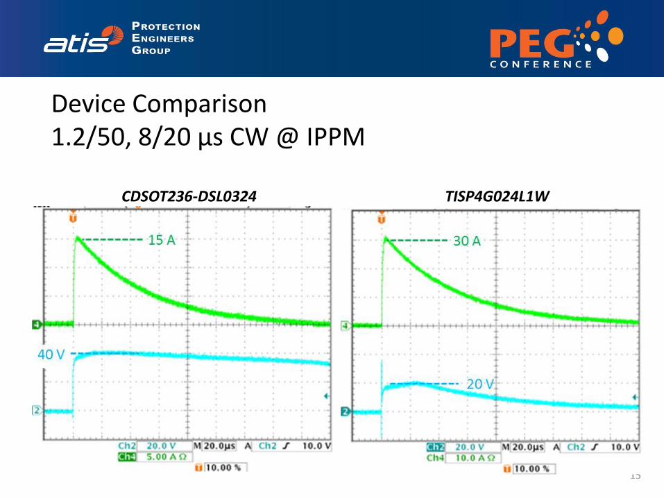
30 A
20 V
40 V
15 A
CDSOT236-DSL0324 TISP4G024L1W
Device Comparison 1.2/50, 8/20 µs CW @ IPPM
Comparison with a certain VDSL2 Class H Line Driver…
• With DSL03: MOVs were required to pass testing.
Line Driver does not survive power induction tests with oscillating GDTs
• With TISP4G: MOVs were not required to pass
testing. Line Driver survives power induction tests with oscillating GDTs, and does so for longer than the 1 second requirement
16
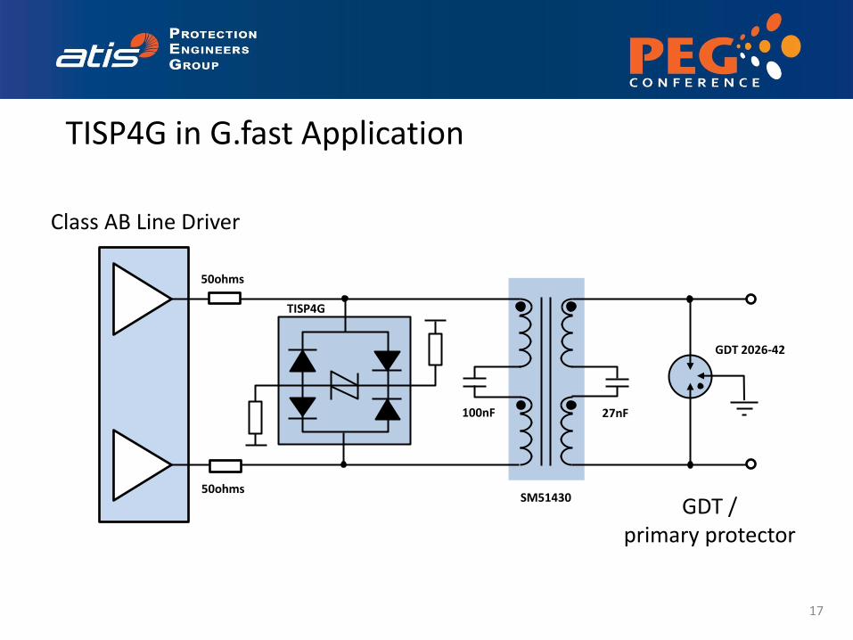
TISP4G
50ohms
50ohms
100nF 27nF
SM51430
Class AB Line Driver
TISP4G in G.fast Application
GDT 2026-42
GDT / primary protector
17

TISP4G
50ohms
50ohms
100nF 27nF
SM51430
Class AB Line Driver
TISP4G in G.fast Application
GDT 2026-42
GDT / primary protector
18
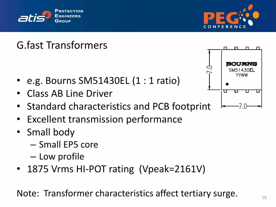
G.fast Transformers
• e.g. Bourns SM51430EL (1 : 1 ratio) • Class AB Line Driver • Standard characteristics and PCB footprint • Excellent transmission performance • Small body
– Small EP5 core – Low profile
• 1875 Vrms HI-POT rating (Vpeak=2161V)
Note: Transformer characteristics affect tertiary surge.
19
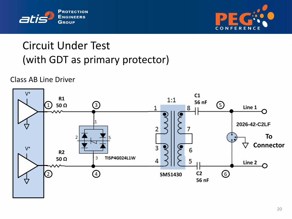
V+
V+ R1
50 Ω
C1 56 nF
C2 56 nF
SM51430
R2 50 Ω
To Connector
2026-42-C2LF
1
2 4
3 5
6
Line 1
Line 2
Circuit Under Test (with GDT as primary protector)
Class AB Line Driver
20
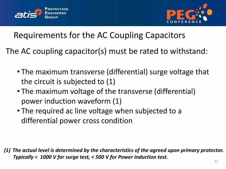
Requirements for the AC Coupling Capacitors
21
The AC coupling capacitor(s) must be rated to withstand:
• The maximum transverse (differential) surge voltage that the circuit is subjected to (1) • The maximum voltage of the transverse (differential)
power induction waveform (1) • The required ac line voltage when subjected to a
differential power cross condition
(1) The actual level is determined by the characteristics of the agreed upon primary protector. Typically < 1000 V for surge test, < 500 V for Power Induction test.
Requirements for the Transformer
22
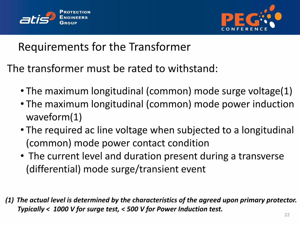
The transformer must be rated to withstand:
• The maximum longitudinal (common) mode surge voltage(1) • The maximum longitudinal (common) mode power induction
waveform(1) • The required ac line voltage when subjected to a longitudinal
(common) mode power contact condition • The current level and duration present during a transverse
(differential) mode surge/transient event
(1) The actual level is determined by the characteristics of the agreed upon primary protector. Typically < 1000 V for surge test, < 500 V for Power Induction test.
23
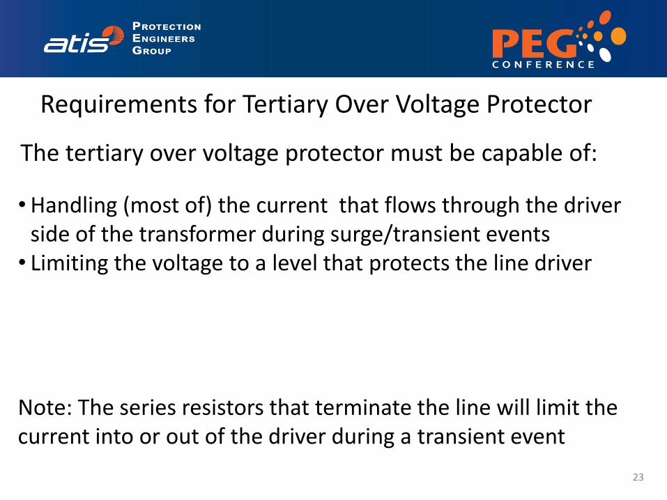
The tertiary over voltage protector must be capable of:
•Handling (most of) the current that flows through the driver side of the transformer during surge/transient events • Limiting the voltage to a level that protects the line driver
Note: The series resistors that terminate the line will limit the current into or out of the driver during a transient event
Requirements for Tertiary Over Voltage Protector
• The AC coupling caps (when sufficiently rated) protect the design against damage from a power induction or power contact event. The line current is only a few mA.
24
Additional Information
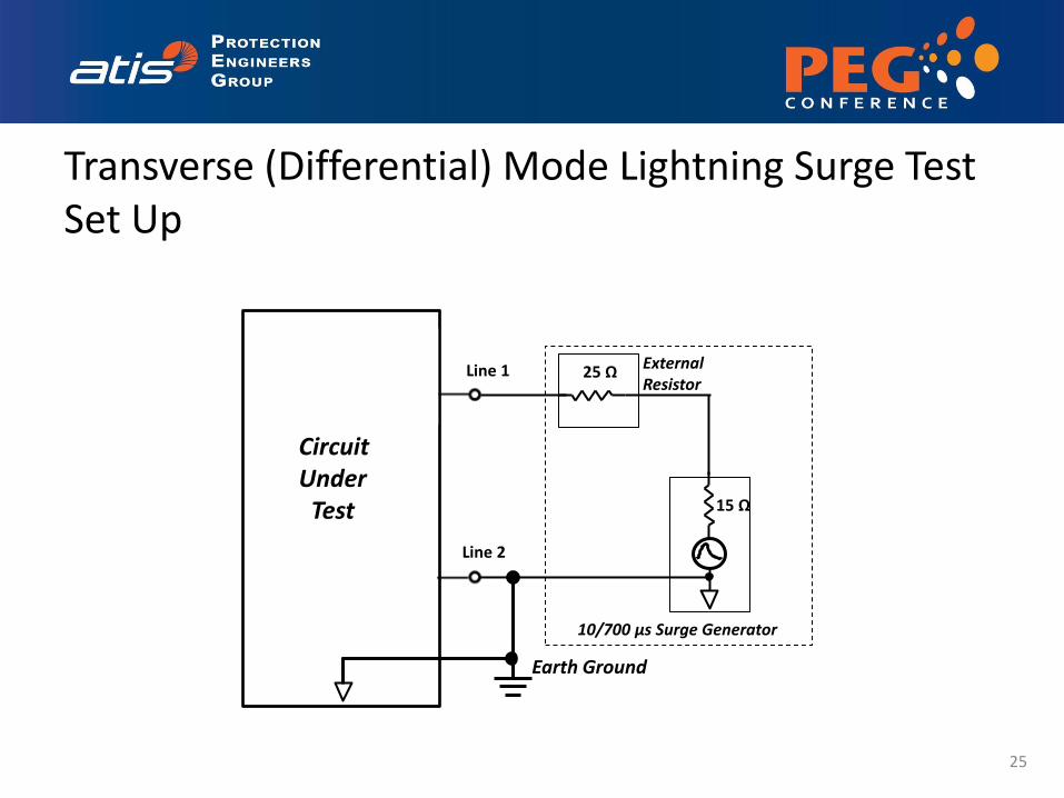
Transverse (Differential) Mode Lightning Surge Test Set Up
Circuit Under
Test
25 Ω
10/700 μs Surge Generator
External Resistor
15 Ω
Earth Ground
Line 1
Line 2
25

Longitudinal (Common) Mode Lightning Surge Test Set Up
Circuit Under
Test
25 Ω
10/700 μs Surge Generator
External Resistors
15 Ω
25 Ω
Earth Ground
Line 1
Line 2
26

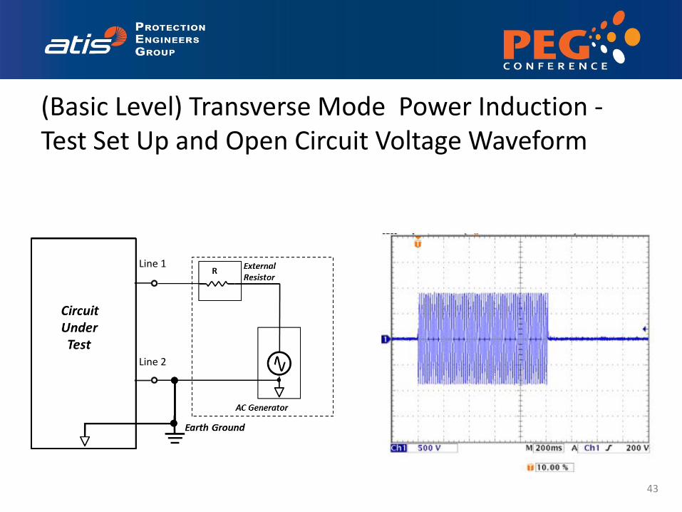
(Basic Level) Transverse Mode Power Induction - Test Set Up and Open Circuit Voltage Waveform
Line 1
Line 2
27
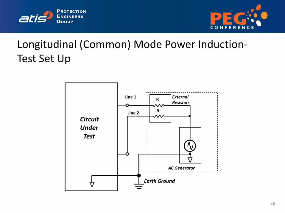
Longitudinal (Common) Mode Power Induction- Test Set Up
Circuit Under
Test
R
AC Generator
External Resistors
R
Earth Ground
Line 1
Line 2
28
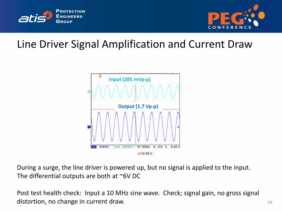
Input (285 mVp-p)
Output (1.7 Vp-p)
Line Driver Signal Amplification and Current Draw
During a surge, the line driver is powered up, but no signal is applied to the input. The differential outputs are both at ~6V DC Post test health check: Input a 10 MHz sine wave. Check; signal gain, no gross signal distortion, no change in current draw. 29
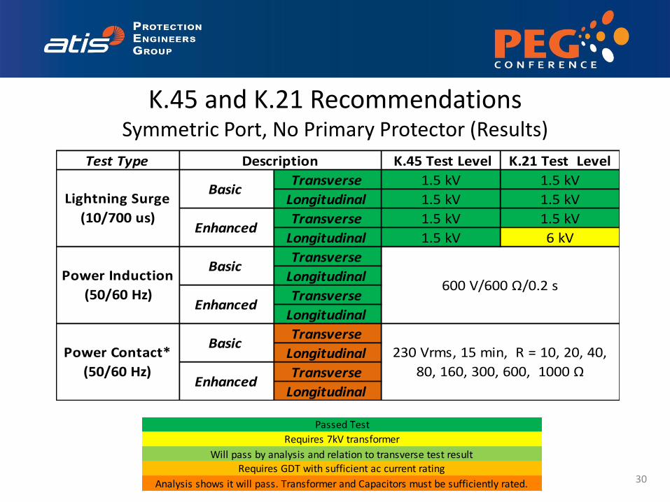
K.45 and K.21 Recommendations Symmetric Port, No Primary Protector (Results)
30
Passed Test
Requires 7kV transformer
Will pass by analysis and relation to transverse test resultRequires GDT with sufficient ac current rating
Analysis shows it will pass. Transformer and Capacitors must be sufficiently rated.
Test Type K.45 Test Level K.21 Test Level
Transverse 1.5 kV 1.5 kV
Longitudinal 1.5 kV 1.5 kV
Transverse 1.5 kV 1.5 kV
Longitudinal 1.5 kV 6 kV
Transverse
Longitudinal
Transverse
Longitudinal
Transverse
Longitudinal
Transverse
Longitudinal
Power Induction
(50/60 Hz)
Basic
600 V/600 Ω/0.2 s
Enhanced
Power Contact*
(50/60 Hz)
Basic230 Vrms, 15 min, R = 10, 20, 40,
80, 160, 300, 600, 1000 ΩEnhanced
Description
Lightning Surge
(10/700 us)
Basic
Enhanced
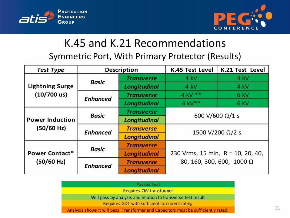
K.45 and K.21 Recommendations Symmetric Port, With Primary Protector (Results)
31
Test Type K.45 Test Level K.21 Test Level
Transverse 4 kV 4 kV
Longitudinal 4 kV 4 kV
Transverse 4 kV ** 6 kV
Longitudinal 4 kV** 6 kV
Transverse
Longitudinal
Transverse
Longitudinal
Transverse
Longitudinal
Transverse
Longitudinal
Description
Lightning Surge
(10/700 us)
Basic
Enhanced
Power Induction
(50/60 Hz)
Basic 600 V/600 Ω/1 s
Enhanced 1500 V/200 Ω/2 s
Power Contact*
(50/60 Hz)
Basic230 Vrms, 15 min, R = 10, 20, 40,
80, 160, 300, 600, 1000 ΩEnhanced
Passed Test
Requires 7kV transformer
Will pass by analysis and relation to transverse test resultRequires GDT with sufficient ac current rating
Analysis shows it will pass. Transformer and Capacitors must be sufficiently rated.
• The Next Generation protectors improve protection for VDSL2 line drivers, and eliminate the need for MOVs (for any line driver)
• New protectors handle tertiary spikes caused by GDT spark over
• Results indicate the solution has the potential to pass;
– ITU-T K.45 enhanced recommendations with and without a primary protector
– ITU-T K.21 basic recommendations without a primary protector
– ITU-T K.21 basic and enhanced recommendations with a primary protector
• However, to pass the K.21 enhanced recommendation without a primary protector requires a transformer capable of withstanding a 6kV longitudinal surge (This was not tested)
32
Summary
• Track changes to the requirements for G.fast network equipment and adjust our testing
• Repeat for GR-1089 Requirements
• Study the impact of Reverse Power Feed
33
Potential Next Steps

Thank You!
Details of Testing The following foils provide details on the response to select tests, and the results of simulation and analysis
35
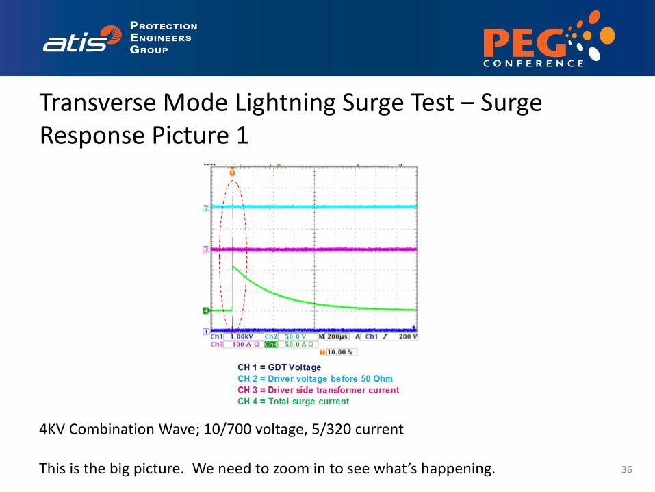
Transverse Mode Lightning Surge Test – Surge Response Picture 1
4KV Combination Wave; 10/700 voltage, 5/320 current This is the big picture. We need to zoom in to see what’s happening. 36
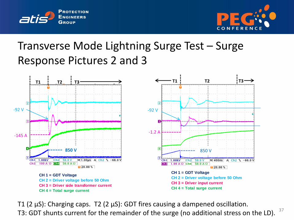
Transverse Mode Lightning Surge Test – Surge Response Pictures 2 and 3
850 V
T1 T2 T3
-92 V
-145 A
CH 1 = GDT Voltage
CH 2 = Driver voltage before 50 Ohm
CH 3 = Driver side transformer current
CH 4 = Total surge current
850 V
-1.2 A
-92 V
CH 1 = GDT Voltage
CH 2 = Driver voltage before 50 Ohm
CH 3 = Driver input current
CH 4 = Total surge current
T1 T2 T3
T1 (2 µS): Charging caps. T2 (2 µS): GDT fires causing a dampened oscillation. T3: GDT shunts current for the remainder of the surge (no additional stress on the LD).
37

Transverse Mode Lightning Surge Test – Surge Response Pictures 2 and 3
850 V
T1 T2 T3
-92 V
-145 A
CH 1 = GDT Voltage
CH 2 = Driver voltage before 50 Ohm
CH 3 = Driver side transformer current
CH 4 = Total surge current
850 V
-1.2 A
-92 V
CH 1 = GDT Voltage
CH 2 = Driver voltage before 50 Ohm
CH 3 = Driver input current
CH 4 = Total surge current
T1 T2 T3
T1 (2 µS): Charging caps. T2 (2 µS): GDT fires causing a dampened oscillation. T3: GDT shunts current for the remainder of the surge (no additional stress on the LD).
38
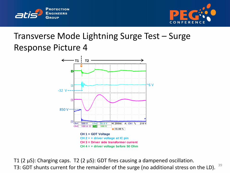
Transverse Mode Lightning Surge Test – Surge Response Picture 4
CH 1 = GDT Voltage
CH 2 = + driver voltage at IC pin
CH 3 = Driver side transformer current
CH 4 = + driver voltage before 50 Ohm
850 V
~6 V
-32 V
T1 T2
T1 (2 µS): Charging caps. T2 (2 µS): GDT fires causing a dampened oscillation. T3: GDT shunts current for the remainder of the surge (no additional stress on the LD).
39
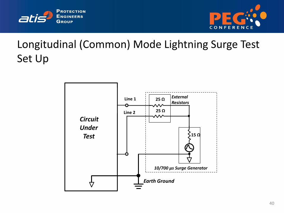
Longitudinal (Common) Mode Lightning Surge Test Set Up
Circuit Under
Test
25 Ω
10/700 μs Surge Generator
External Resistors
15 Ω
25 Ω
Earth Ground
Line 1
Line 2
40
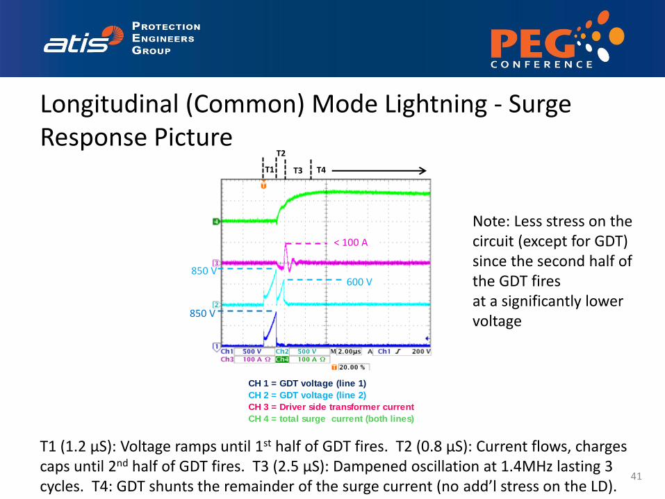
Longitudinal (Common) Mode Lightning - Surge Response Picture
T1
T2
T3 T4
850 V
850 V 600 V
< 100 A
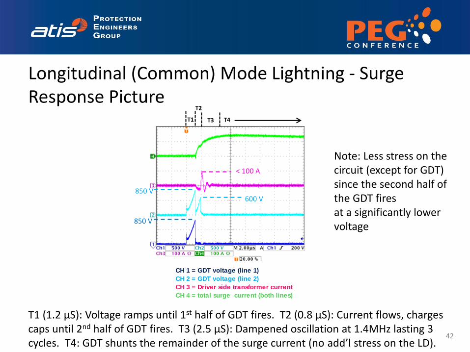
CH 1 = GDT voltage (line 1)
CH 2 = GDT voltage (line 2)
CH 3 = Driver side transformer current
CH 4 = total surge current (both lines)
Note: Less stress on the circuit (except for GDT) since the second half of the GDT fires at a significantly lower voltage
T1 (1.2 µS): Voltage ramps until 1st half of GDT fires. T2 (0.8 µS): Current flows, charges caps until 2nd half of GDT fires. T3 (2.5 µS): Dampened oscillation at 1.4MHz lasting 3 cycles. T4: GDT shunts the remainder of the surge current (no add’l stress on the LD).
41
Longitudinal (Common) Mode Lightning - Surge Response Picture
T1
T2
T3 T4
850 V
850 V 600 V
< 100 A
CH 1 = GDT voltage (line 1)
CH 2 = GDT voltage (line 2)
CH 3 = Driver side transformer current
CH 4 = total surge current (both lines)
Note: Less stress on the circuit (except for GDT) since the second half of the GDT fires at a significantly lower voltage
T1 (1.2 µS): Voltage ramps until 1st half of GDT fires. T2 (0.8 µS): Current flows, charges caps until 2nd half of GDT fires. T3 (2.5 µS): Dampened oscillation at 1.4MHz lasting 3 cycles. T4: GDT shunts the remainder of the surge current (no add’l stress on the LD).
42
(Basic Level) Transverse Mode Power Induction - Test Set Up and Open Circuit Voltage Waveform
Line 1
Line 2
43
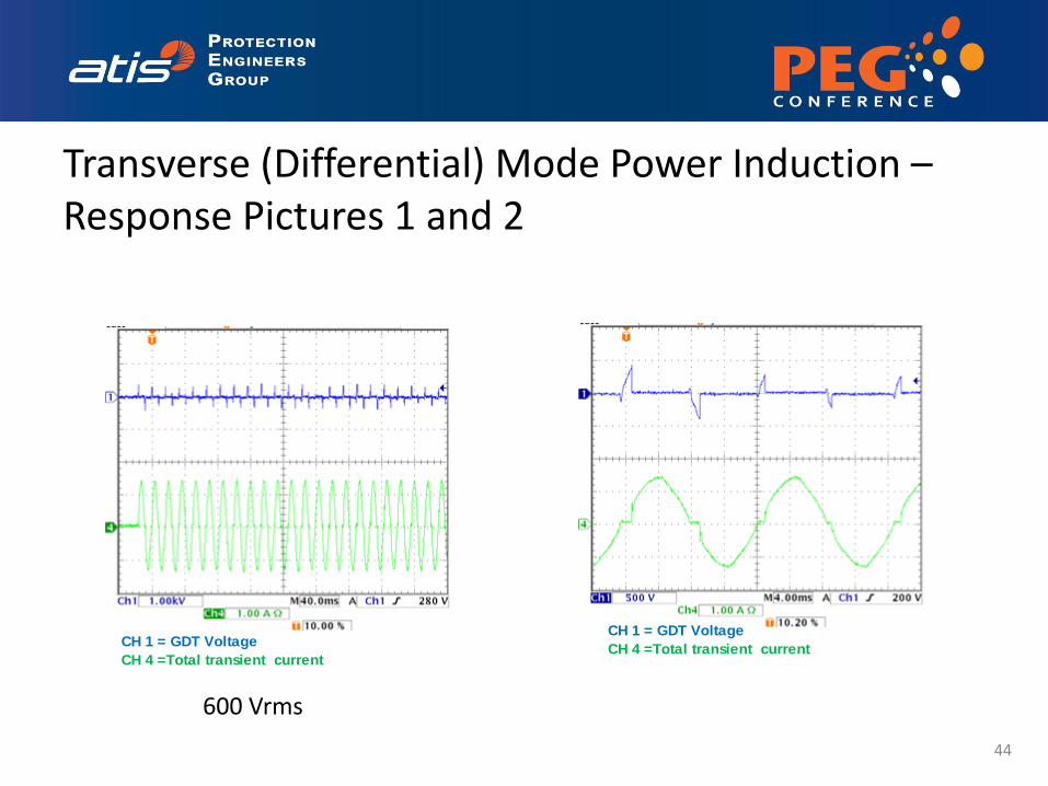
Transverse (Differential) Mode Power Induction – Response Pictures 1 and 2
600 Vrms
CH 1 = GDT Voltage
CH 4 =Total transient current
CH 1 = GDT Voltage
CH 4 =Total transient current
44
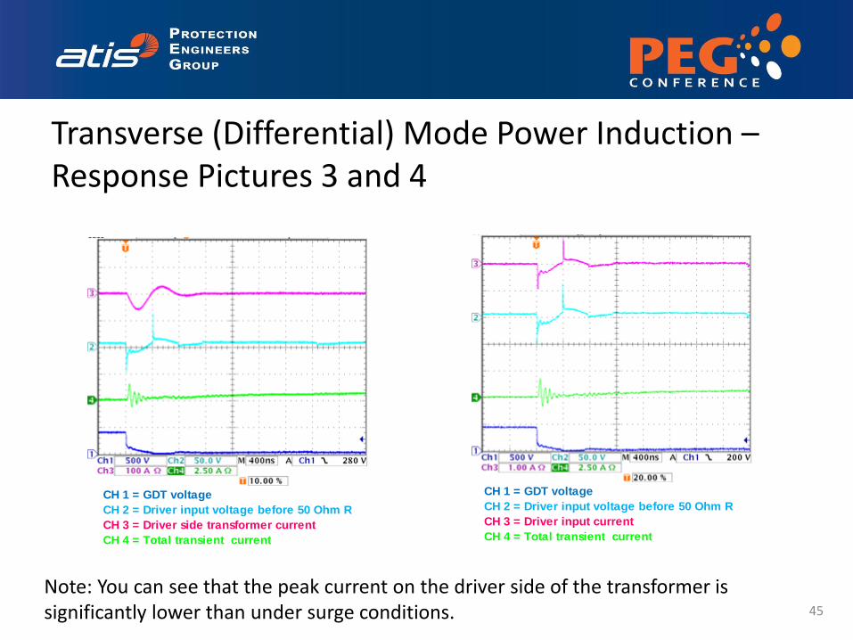
Transverse (Differential) Mode Power Induction – Response Pictures 3 and 4
CH 1 = GDT voltage
CH 2 = Driver input voltage before 50 Ohm R
CH 3 = Driver side transformer current
CH 4 = Total transient current
CH 1 = GDT voltage
CH 2 = Driver input voltage before 50 Ohm R
CH 3 = Driver input current
CH 4 = Total transient current
Note: You can see that the peak current on the driver side of the transformer is significantly lower than under surge conditions. 45
Conclusions on Transverse Power Induction
46
• The circuit provides excellent protection against damage from the basic level transverse mode power Induction test.
• The stress on the driver after the GDT fires is minimal due to the low clamping voltage of the TISP4G.
• The transient energy is absorbed by the GDT, the TISP4G and the transformer.
• The peak stress levels on the line driver are much lower than the lightning surge case.
• The average stress over one cycle of the 60 Hz waveform is very low.
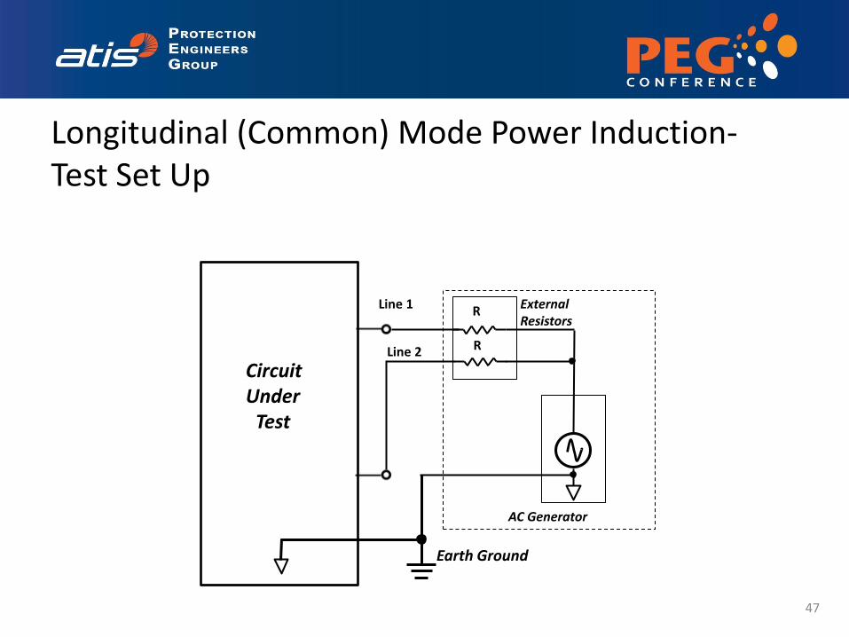
Longitudinal (Common) Mode Power Induction- Test Set Up
Circuit Under
Test
R
AC Generator
External Resistors
R
Earth Ground
Line 1
Line 2
47
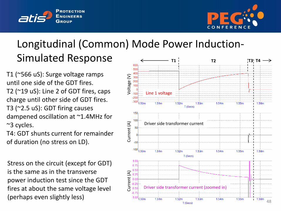
Longitudinal (Common) Mode Power Induction- Simulated Response
T1 T2 T3
Line 1 voltage
Driver side transformer current
Driver side transformer current (zoomed in)
Vo
ltag
e (V
) C
urr
ent
(A)
Cu
rren
t (A
)
T4
Stress on the circuit (except for GDT) is the same as in the transverse power induction test since the GDT fires at about the same voltage level (perhaps even slightly less)
T1 (~566 uS): Surge voltage ramps until one side of the GDT fires. T2 (~19 uS): Line 2 of GDT fires, caps charge until other side of GDT fires. T3 (~2.5 uS): GDT firing causes dampened oscillation at ~1.4MHz for ~3 cycles. T4: GDT shunts current for remainder of duration (no stress on LD).
48
49
• Same test setup as basic level test • 1500 Vrms waveform (vs. 600 Vrms) • 200 ohm series resistor (vs. 600 ohm)
– 7.5 Arms
• 2 second duration (vs. 1 sec)
• Transverse (Differential) Mode Power Induction Test
• Longitudinal (Common) Mode Power Induction Test
Enhanced Level Power Induction Test
50
Transverse (Differential) Mode Power Induction Test
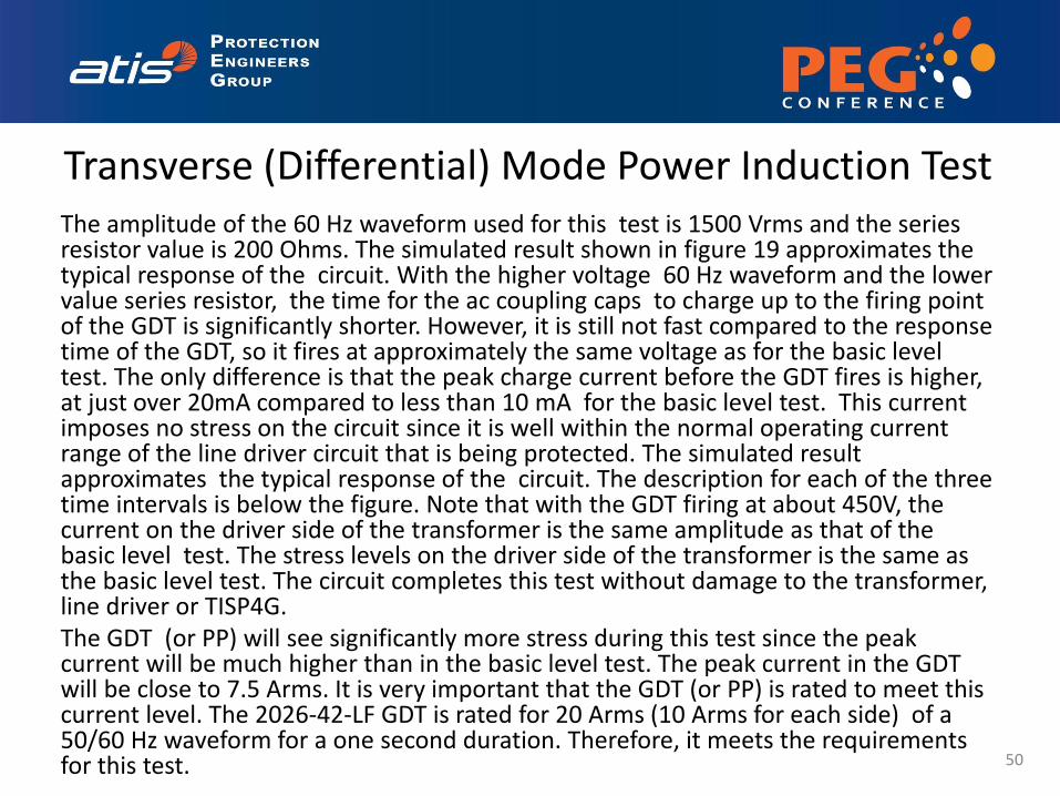
The amplitude of the 60 Hz waveform used for this test is 1500 Vrms and the series resistor value is 200 Ohms. The simulated result shown in figure 19 approximates the typical response of the circuit. With the higher voltage 60 Hz waveform and the lower value series resistor, the time for the ac coupling caps to charge up to the firing point of the GDT is significantly shorter. However, it is still not fast compared to the response time of the GDT, so it fires at approximately the same voltage as for the basic level test. The only difference is that the peak charge current before the GDT fires is higher, at just over 20mA compared to less than 10 mA for the basic level test. This current imposes no stress on the circuit since it is well within the normal operating current range of the line driver circuit that is being protected. The simulated result approximates the typical response of the circuit. The description for each of the three time intervals is below the figure. Note that with the GDT firing at about 450V, the current on the driver side of the transformer is the same amplitude as that of the basic level test. The stress levels on the driver side of the transformer is the same as the basic level test. The circuit completes this test without damage to the transformer, line driver or TISP4G. The GDT (or PP) will see significantly more stress during this test since the peak current will be much higher than in the basic level test. The peak current in the GDT will be close to 7.5 Arms. It is very important that the GDT (or PP) is rated to meet this current level. The 2026-42-LF GDT is rated for 20 Arms (10 Arms for each side) of a 50/60 Hz waveform for a one second duration. Therefore, it meets the requirements for this test.
51
Longitudinal (Common) Mode Power Induction Test
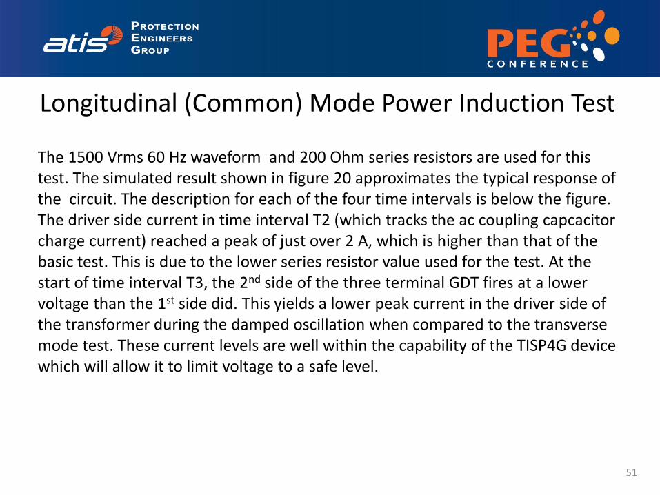
The 1500 Vrms 60 Hz waveform and 200 Ohm series resistors are used for this test. The simulated result shown in figure 20 approximates the typical response of the circuit. The description for each of the four time intervals is below the figure. The driver side current in time interval T2 (which tracks the ac coupling capcacitor charge current) reached a peak of just over 2 A, which is higher than that of the basic test. This is due to the lower series resistor value used for the test. At the start of time interval T3, the 2nd side of the three terminal GDT fires at a lower voltage than the 1st side did. This yields a lower peak current in the driver side of the transformer during the damped oscillation when compared to the transverse mode test. These current levels are well within the capability of the TISP4G device which will allow it to limit voltage to a safe level.
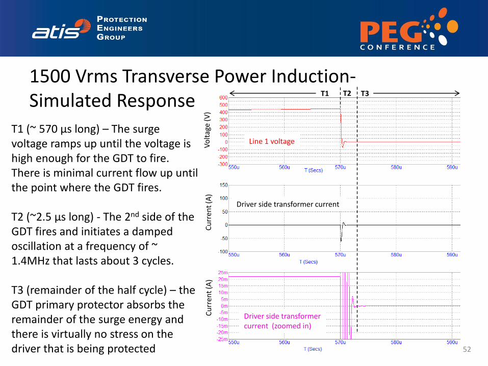
1500 Vrms Transverse Power Induction- Simulated Response
T1 (~ 570 μs long) – The surge voltage ramps up until the voltage is high enough for the GDT to fire. There is minimal current flow up until the point where the GDT fires. T2 (~2.5 μs long) - The 2nd side of the GDT fires and initiates a damped oscillation at a frequency of ~ 1.4MHz that lasts about 3 cycles. T3 (remainder of the half cycle) – the GDT primary protector absorbs the remainder of the surge energy and there is virtually no stress on the driver that is being protected 52
T1 T3
Line 1 voltage
Driver side transformer current
Driver side transformer current (zoomed in)
Vo
ltag
e (V
) C
urr
ent
(A)
Cu
rren
t (A
)
T2
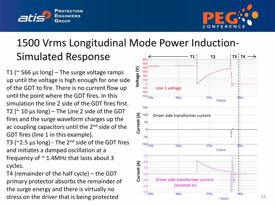
1500 Vrms Longitudinal Mode Power Induction- Simulated Response
T1 (~ 566 μs long) – The surge voltage ramps up until the voltage is high enough for one side of the GDT to fire. There is no current flow up until the point where the GDT fires. In this simulation the line 2 side of the GDT fires first. T2 (~ 10 μs long) – The Line 2 side of the GDT fires and the surge waveform charges up the ac coupling capacitors until the 2nd side of the GDT fires (line 1 in this example). T3 (~2.5 μs long) - The 2nd side of the GDT fires and initiates a damped oscillation at a frequency of ~ 1.4MHz that lasts about 3 cycles. T4 (remainder of the half cycle) – the GDT primary protector absorbs the remainder of the surge energy and there is virtually no stress on the driver that is being protected 53
Line 1 voltage
Driver side transformer current
Driver side transformer current (zoomed in)
Vo
ltag
e (V
) C
urr
ent
(A)
Cu
rren
t (A
)
T1 T2 T3 T4
54
• Same test setups as the power induction tests, except; – 230 Vrms signal – Resistor values ranging from 10 to 1K ohms
• Longitudinal (Common) Mode Power Contact Test
• Transverse (Differential) Mode Power Contact Test
Power Contact
55
Longitudinal (Common) Mode Power Contact Test
The capability to withstand the longitudinal mode power contact test strictly depends on the high potential (Hi-Pot) capability of the signal transformer. As long as the transformer does not breakdown, the current flow will be negligible. Any current flow will be a function of the interwinding capacitance (20 pF maximum for the Bourns SM51430) and the insulation resistance of the transformer. be the current required to charge and discharge the interwinding capacitance and any parasitic capacitance in the circuit on the line side of the transformer. Given this low value of capacitance, the current will be orders of magnitude lower than the current required to charge the two 56nF ac coupling capacitors in the previous test. Given that the Bourns SM51430 transformer used in the test circuit is sufficiently rated to withstand 230Vrms from primary to secondary, the circuit will pass this test.
56
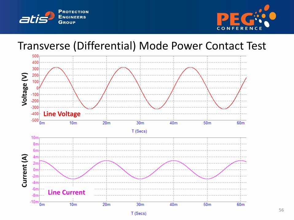
Transverse (Differential) Mode Power Contact Test
Line Voltage
Line Current
Vo
ltag
e (
V)
Cu
rre
nt
(A)


![Welcome [] · VDSL2 with weak FEXT VDSL2 with strong FEXT VDSL2, theoretical with Vectoring Dämpfung FEXT. Downstream [Mbps] – VDSL2 Profile 17a Reichweite Mit Vectoring kann fast](https://static.fdocuments.us/doc/165x107/5e1e042510f3b012214f201d/welcome-vdsl2-with-weak-fext-vdsl2-with-strong-fext-vdsl2-theoretical-with.jpg)