
VASCULAR SUPPLY OF THE OPTIC PATHWAY*
13
Brit. J. Ophthal. (1955) 39, 220. VASCULAR SUPPLY OF THE OPTIC PATHWAY* II. FURTHER STUDIES BY MICRO-ARTERIOGRAPHY OF THE OPTIC NERVE BY J. FRANCOIS, A. NEETENS, AND J. M. COLLETTEt From the Ophthalmological Clinic, University of Ghent (Director, Prof. Fran!rois), and the institute of Radiology, University of Liege (Director, Prof. Leroux) THE literature gives few details of the intimate vascularization of the optic pathway. Leber (1903) found in the optic nerve a vascular network, com- posed of round meshes; he described other vessels running obliquely along the whole length of the optic nerve, which became smaller with more closely woven meshes at the level of the lamina cribrosa. Wolff (1948) agreed with Leber that the distribution of the septa containing the vessels between the nervous tissue bundles reflected the vascular pattern. The branches, which derived from the very rich pial vascular network, penetrated dichotomously into the optic nerve, the septa gradually disappeared towards the intracanalicular and cranial sections, and in the centre the capillaries were less frequent and the meshwork looser (cf. also Behr, 1935). Fazio and Farina (1940) deduced from horizontal sections (not from in- jection) the existence of an irregular quadrangulated meshwork, orientated lengthways, built up by very small capillaries, and of equal density at the periphery and centre. Towards the optic foramen the capillaries and meshes were wider and still more irregular, and in the intracranial section a great number of very small vessels ran parallel. Eisler (1930) indicated the possibility of a network with longitudinal meshes in the sheath of the optic nerve. The subject obviously requires further investigation. Technique At post mortem, the orbital contents are separated from the bone together with the periosteum, and after the superior wall of the optic foramen has been trephined, the orbital roof is removed from the inner side of the skull. The bone of the sella turcica is incised and the sphenoid bone chiselled; the internal carotid artery is taken over as long a distance as possible, and the orbit is removed complete with the optic nerve and its whole vascular supply. In the laboratory the specimen is irrigated for a few minutes; then the internal carotid artery is dissected until the opening of the ophthalmic artery is reached, or, if it is intended to inject the central retinal artery, as far as the branching of this vessel. In some specimens a branch is seen to arise from the ophthalmic artery before the central retinal artery is observed; this is described by Magitot (1908) as running to the dura mater, but in some cases (about one in four) we were able to identify it as a central artery of the optic nerve. Next a fine cannula is inserted into the artery to be injected, and without previous *Received for nublication August 3, 1954. tCandidate of the Belgian Fund for Scientific Research. 220 on March 19, 2022 by guest. Protected by copyright. http://bjo.bmj.com/ Br J Ophthalmol: first published as 10.1136/bjo.39.4.220 on 1 April 1955. Downloaded from
Transcript of VASCULAR SUPPLY OF THE OPTIC PATHWAY*

Brit. J. Ophthal. (1955) 39, 220.
VASCULAR SUPPLY OF THE OPTIC PATHWAY*II. FURTHER STUDIES BY MICRO-ARTERIOGRAPHY
OF THE OPTIC NERVEBY
J. FRANCOIS, A. NEETENS, AND J. M. COLLETTEtFrom the Ophthalmological Clinic, University of Ghent (Director, Prof. Fran!rois),and the institute of Radiology, University ofLiege (Director, Prof. Leroux)
THE literature gives few details of the intimate vascularization of the opticpathway. Leber (1903) found in the optic nerve a vascular network, com-posed of round meshes; he described other vessels running obliquelyalong the whole length of the optic nerve, which became smaller with moreclosely woven meshes at the level of the lamina cribrosa.
Wolff (1948) agreed with Leber that the distribution of the septacontaining the vessels between the nervous tissue bundles reflected thevascular pattern. The branches, which derived from the very rich pialvascular network, penetrated dichotomously into the optic nerve, the septagradually disappeared towards the intracanalicular and cranial sections, andin the centre the capillaries were less frequent and the meshwork looser(cf. also Behr, 1935).
Fazio and Farina (1940) deduced from horizontal sections (not from in-jection) the existence of an irregular quadrangulated meshwork, orientatedlengthways, built up by very small capillaries, and of equal density at theperiphery and centre. Towards the optic foramen the capillaries and mesheswere wider and still more irregular, and in the intracranial section a greatnumber of very small vessels ran parallel.
Eisler (1930) indicated the possibility of a network with longitudinalmeshes in the sheath of the optic nerve.The subject obviously requires further investigation.
TechniqueAt post mortem, the orbital contents are separated from the bone together with
the periosteum, and after the superior wall of the optic foramen has been trephined,the orbital roof is removed from the inner side of the skull. The bone of the sellaturcica is incised and the sphenoid bone chiselled; the internal carotid artery istaken over as long a distance as possible, and the orbit is removed complete withthe optic nerve and its whole vascular supply. In the laboratory the specimen isirrigated for a few minutes; then the internal carotid artery is dissected until theopening of the ophthalmic artery is reached, or, if it is intended to inject the centralretinal artery, as far as the branching of this vessel. In some specimens a branch isseen to arise from the ophthalmic artery before the central retinal artery is observed;this is described by Magitot (1908) as running to the dura mater, but in some cases(about one in four) we were able to identify it as a central artery of the optic nerve.Next a fine cannula is inserted into the artery to be injected, and without previous
*Received for nublication August 3, 1954.tCandidate of the Belgian Fund for Scientific Research.
220
on March 19, 2022 by guest. P
rotected by copyright.http://bjo.bm
j.com/
Br J O
phthalmol: first published as 10.1136/bjo.39.4.220 on 1 A
pril 1955. Dow
nloaded from

VASCULAR SUPPLY OF THE OPTIC PATHWA Y. H 2
irrigation with water the injection is made immediately with Heyden thorotrastsolution:
Colloidal thorium oxide 3 gr.Amyl. semi-invertum 3 gr.Aqua ad 12 ml.
The injection is done without previous irrigation for three reasons:(1) To make a better contrast;(2) Because eventual clotting is avoided by the haemolysis produced by the thorotrast;(3) Because thorotrast solution mixes easily with blood.
The injection is carried out very slowly and under a constant pressure of 25 to30 mm. Hg without clamping the venous outflow. The particle size of thorotrastbeing of the order of 0- 1 ,u, the solution penetrates into even the smallest vessels.Injecting slowly prevents the collapse of the small vessels.The specimens must be fixed as soon as possible, because diffusion out of the
vessel-walls may occur even post mortem. Formalin solution 2-3 per cent. isnot used, as this would prevent the fixation of the thorotrast. A special fixativeis used which has been found entirely satisfactory:
Formalin 10 per cent. ... ... 8 partsAlcohol 96 per cent. saturated with picric acid 6 partsAcetic acid ... ... ... ... 1 partChloroform ... ... ... ... 1 part
This fixes the thorotrast and does not make the specimens rigid or more fragilethan those fixed with formalin 10 per cent.The apparatus has already been described (Franqois and Neetens, 1954).The technique of micro-angiography is new and its application so far very
restricted (Collette, 1953; Bellman, 1953; Bellman and Engstr6m, 1952; Engstr6m,1949, 1951; Engstr6m and Wegstedt, 1951; Barclay, 1951; Bohatyrtschuk, 1944;Brasseur, 1945; Tirman and others, 1951).
(1) Radiology.-The preliminary injection of the vascular system with substancesof high atomic weight simplifies the application of the method, on account of theabsorption which occurs at the site of the injected vessels as compared with thesurrounding medium. Yet it remains necessary to use long-wave rays to obtainsufficient contrast. Our micro-radiographic unit (generator and tube) is veryconvenient in use.
Generator.-This holds in the same container the high voltage transformer and thetransformer used for heating the filament. The primary coils are fed by variable trans-formers; this permits a continuously variable range of 0-50 kV maximum and 0-35 mA.Tube.-We use a Machlett A2 tube with iron target and beryllium window. It is
known that the intensity of the continuous spectrum emitted by an x-ray tube is propor-tional to the atomic number of the element used at the anode. The intensity is low inthis case, since the atomic number of iron is only 26. However, the Fe target emitscharacteristic lines of high intensity and long wave-length (K a 1: 1-936 A; K a 2:1-932 A). The intensity of these characteristic lines increases with the voltage, but thewave-length remains constant. Therefore, in the low-voltage range, the intensity of thecontinuous spectrum will be negligible compared with the characteristic radiation. Thelatter, however, is soft and rapidly absorbed by air. This makes it necessary to use ashort focal length in order to take full advantage of the intense monochromatic radiation.
Accessories.-Our tube is equipped with a 1 5-mm. focus, but the beryllium windowhas a small diameter and reduces the effective beam angle to 100.
221
on March 19, 2022 by guest. P
rotected by copyright.http://bjo.bm
j.com/
Br J O
phthalmol: first published as 10.1136/bjo.39.4.220 on 1 A
pril 1955. Dow
nloaded from

J. FRAN(7OIS, A. NEETENS, AND J. M. COLLETTE
The film-holder has been designed to permit the coverage of a circular field 25 mm. indiameter (Fig. 1). The least distance from source to object is 13 * 5 cm.
FIG. 1.-Details of tube;note film-holder on extremeleft.
I
Long exposures are necessary and require all parts of the system to be firmly joinedtogether. The film-holder (Fig. 2, III, IV, V) is joined to the tube by a number of inter-mediary components. First an adapter (Fig. 2, VI) is screwed onto the tube window and
I
x~~~~~~~~~~~~~~~~~~~~TM-~~~~~~~~~~~
JmFIG. 2.-Diagram of tubeand film-holder.
222
on March 19, 2022 by guest. P
rotected by copyright.http://bjo.bm
j.com/
Br J O
phthalmol: first published as 10.1136/bjo.39.4.220 on 1 A
pril 1955. Dow
nloaded from

VASCULAR SUPPLY OF THE OPTIC PATHWAY. H2
holds an intermediary cone (Fig. 2, VII). The film-holder itself may be screwed directlyto this cone, but it is also possible to use extension rings (each 1 cm. wide) between thefilm-holder and the cone to give a greater focal length.A disk holding the histological sample and the film is inserted into a circular
hole bored in the cover of the film-holder. There must be a close contact betweenthe film emulsion and the sample. The latter is never completely dry and a non-hygroscopic support separates it from the film. We usually put the samplebetween two sheets of " Styrafoil " 1/100 in. thick, the upper sheet providing theclose contact required when the film-holder is closed.The sample is removed from the fixing solution immediately before being x-
rayed. The excess fluid is eliminated, but the preparation must remain moist asdesiccation may cause change in volume with consequent motion during exposure.
(2) Photography.-The main photographic problem is to find a film with a fineenough grain. Two emulsions have been found suitable: " Maximum Resolu-
tion" film (Kodak) resolution 1,000 lines, and"Lippman " film (Gevaert) resolution 500 lines.The latter was used in this study. The grain of an
As emulsion is roughly proportional to its speed, andthis fine-grain film requires long exposures. Thefollowing conditions were observed throughout:
(1) thickness of preparation never above 400 ,u;(2) dimensions of preparation small;(3) preparation richly vascularized;(4) outside opacified vascular bed, x-ray absorption
kept to a minimum.When the ideal values of the variable elements
are contradictory, a compromise must be adoptedobserving the following conditions:
(1) the monochromatic radiation should have a\ Ia large wave-length;
(2) its intensity should be as great as possiblecompared with the continuous spectrum, to takeadvantage of the characteristic radiation and to keepthe exposures as short as possible;
(3) the focal distance should be as short as iscompatible with sufficient field coverage and accept-able geometrical diffusion.The first two conditions are respected when
V= 2 Vo, V= actual voltage, and Vo= lowestd voltage for characteristic line. In this case, V=
12 -8 KV. In these conditions, with a current ofb l 18 mA and a focal distance of 13 5 cm, the length
Il\b of exposure varies from 2 to 5 minutes.Calculation of the geometrical projection makes
p. Uu p it possible to evaluate the relative importance in thepicture of shadow (U) and dimness (P) as in Fig. 3:
FIG. 3.-Diagram illustrating a.d - b.f bcalculation of U (shadow) and P U_ and P= fdimness). a-b a-b
223
on March 19, 2022 by guest. P
rotected by copyright.http://bjo.bm
j.com/
Br J O
phthalmol: first published as 10.1136/bjo.39.4.220 on 1 A
pril 1955. Dow
nloaded from

J. FRAN(9OIS, A. NEETENS, AND J. M. COLLETTE
These formulae show that the picture-size is slightly smaller than the objectitself while the dimness is practically negligible.
ResultsThe horizontal and parasagittal sections are exactly identical and present
a picture of rectangles, squares, or more rarely irregular circles; their sizedepends on the relative length of the collateral branches of the vesselsrunning in an antero-posterior direction.
(C)~~~~~~~b
(d)FIG. 4.-Scheme of vascular patterns in optic nerve:(a) Building up of pentagons from L.C.U.(b) Splitting of L.C.U. and structure of circular unit.(c) Structure of circular unit in transverse section.(d) Nutrition of central retinal artery and vein
Two definite types of unit (Fig. 4) were found to compose the vascularpattern of the optic nerve:
(1) Transverse.-These have a pentagonal form, and encircle the nerve-bundlesas complete or incomplete rings over its whole length at regular distances (Fig. 5,opposite).
This circular unit should be compared with the arterial circle of Zinn. with thedistinction that the latter serves the whole nerve, the former only part of a singlebundle.
(2) Longitudinal.-These run in an antero-posterior direction, and all branchesresponsible for further vascular patterns disposed between different bundles in theinterfascicular spaces' derive from them. They may be called longitudinalcapillary units (L.C.U.) (Fig. 6, opposite).
224
on March 19, 2022 by guest. P
rotected by copyright.http://bjo.bm
j.com/
Br J O
phthalmol: first published as 10.1136/bjo.39.4.220 on 1 A
pril 1955. Dow
nloaded from

VASCULAR SUPPLY OF THE OPTIC PATHWA Y. II(b) (c )
(a)FIG. 5.-Or. x 12. Anterior. Longitudinal section.
(a) Right, central artery and vein superimposed.(b) Quadrangulated form.(c) Curved vessels.
FIG. 6.-Or. x 22. Posterior part.Transverse section (slightly obli-que). Meshes a little widercentrally.
These structures may not all be situated in the same perpendicular plane.The arteries which enter the optic nerve arise from the pial network where
they anastomose frequently to build up a plexus. Hence they give offcapillaries, and these, branching dichotomously at first, irrigate the opticnerve-fibres, forming L.C.Us. Other arteries penetrate into the opticnerve at the arteriole stage, and, running to the centre, give rise to collateralvessels (L.C.Us) which anastomose with capillaries from the pial network.The most important of these arteries, the central artery of the optic nerve,
does not branch off haphazardly, but participates in building up regularvascular units.These arteries do not subdivide progressively, but undergo a rapid trans-
ition to the capillary stage. This, like the choroidal circulation, recalls the
225
on March 19, 2022 by guest. P
rotected by copyright.http://bjo.bm
j.com/
Br J O
phthalmol: first published as 10.1136/bjo.39.4.220 on 1 A
pril 1955. Dow
nloaded from

J. FRAN(7OIS, A. NEETENS, AND J. M. COLLETTE
embryological development of the optic vessels, the abrupt transition to thearterioles indicating that the capillary network developed before the differentarteries existed, the hyaloid artery having no nutritive connection with theoptic pathway.The collateral vessels from the L.C.U. may vary in length; they may
anastomose with other collaterals from other L.C.Us and then form apentagon (Fig. 6).
After running longitudinally close to the L.C.U., the collateral vesselderived from another L.C.U. may bend at right angles and return to thesame L.C.U., or it may pass beyond one pentagon and help in constructingother pentagons further on (Figs 7 and 8).
FIG. 7.-Or. x 32. Middle. Longitudinal section. Regular network.(a) Large transverse veins.(b) Quadrangulated appearance of meshes.(c) Different L.C.U. in single space.
g ,., _ - A. V Pi ~ baAl_R_.
FIG. 8.-Or. x 32. Posterior. Longitudinal section.(a) Posterior branch of central artery of optic nerve.(b) Capillary system stream-lined.
226
on March 19, 2022 by guest. P
rotected by copyright.http://bjo.bm
j.com/
Br J O
phthalmol: first published as 10.1136/bjo.39.4.220 on 1 A
pril 1955. Dow
nloaded from

VASCULAR SUPPLY OF THE OPTIC PATHWAY. II
The L.C.U. may also give off smaller branches running longitudinally;it may subdivide transversely or longitudinally with no change in calibre, andno anastomosis apparently interrupting the continuity of the vascularization.
Capillaries may also arise from the L.C.U. and curve transversely over oneor more bundles like the fingers of a hand; these may combine and othervessels may arise from their union. An L.C.U. may not correspond withthe angles of the pentagon, and some structures may arise from the sides.On the outer side we see oval loops and figures of eight. Both on the
outer and inner sides vessels may run parallel to the side of a pentagon andrejoin it after some distance (Fig. 9). The outer collaterals form com-municating links between the pentagons, or form one or more sides of newpentagons. Vessels may even be seen to start from an angle and run to theopposite side, dividing the pentagon into two unequal parts. On the innerside, the pentagons may give rise to tiny vessels forming in the centre (Fig. 10).
FIG. 9.-Or. x 95. Mid-dle. Transverse section.Note fine detail ofbuilding up of penta-gons, forming ovaladnexa (arrow) to sup-ply efferent nerve fibresfor another bundle.General structure moreirregular than in poster-ior part.
FIG. 10.--Or. x95. An-tenior. Transverse sec-tion (oblique).(a) Curved vessels given
(b) Corkscrew capillar-ies starting from innerside of pentagon.The pentagons become
(I)) more circular and theoriginal pattern is pro-gressively lost towardsthe papilla.
ta I
227
on March 19, 2022 by guest. P
rotected by copyright.http://bjo.bm
j.com/
Br J O
phthalmol: first published as 10.1136/bjo.39.4.220 on 1 A
pril 1955. Dow
nloaded from

J. FRAN 7OIS, A. NEETENS, AND J. M. COLLETTE
FIG. 11. -Or. x 95.Middle. Longitudinalsection. L.C.Us, circu-lar vascular units, andtheir collaterals are alltangled together.
FIG. 12. - Or. x 95.Posterior. Transversesection. Meshes larger.
This vascular pattern corresponds with the nervous tissue structure andthe myelo-architecture, confirming the ideas of Leber (1903), Wolff (1948),and Fazio and Farina (1940). The oval capillary meshes appear to surroundnerve fibres which leave one bundle and join another, the bundles not beingneural units (Behr, 1935).
In the interfascicular spaces, capillaries of different sizes may be found;the large ones are venous return-capillaries, the middle-sized are mostlyarteries, and the small ones form a subsidiary nutritional system for thenerve bundles.
At the periphery of the optic nerve the outermost bundles are, surroundedby a special vascular ring formed by the pia mater capillary-plexus, by' the
228
v44,W..11
.wr..
on March 19, 2022 by guest. P
rotected by copyright.http://bjo.bm
j.com/
Br J O
phthalmol: first published as 10.1136/bjo.39.4.220 on 1 A
pril 1955. Dow
nloaded from

VASCULAR SUPPLY OF THE OPTIC PATHWA Y. II
FIG. 13. - Or. x 65.Transition of vesselsfrom optic nerve sheathto optic nerve. Char-acteristic encircling of .3pouter bundles. afterdichotomous branching .....
(afrow).
penetrating capillaries, and by the branches of the first dichotomously dividingvessels (Fig. 13). At the centre of the optic nerve, the network seems to be alittle denser. The description of these structures is most typical of themiddle third of the intra-orbital portion of the optic nerve (Figs 7-1 1).Approaching the lamina cribrosa the capillaries become tortuous, cork-
screwed, and curly, and they wind spirally into the optic nerve itself.(Fig. 14).
(a)~~~~~~~~~~~~~~~~~~~~~~~~~~~~~~~~~~~~~I
FIG. 14.-Or. x 48. Papilla, lamina cribrosa, and central retinal vessels.(a) Heavily curied appearance, centre constituting physiological excavation(b) Transition of vessels from circle of Zinn to lamina cribrosa.
At the lamina cribrosa this subdivision is no longer seen. Many othercapillary branches (probably deriving from anterior -ramifications of thecentral artery of the optic nerve, and from vessels of the ciliary system)
229
on March 19, 2022 by guest. P
rotected by copyright.http://bjo.bm
j.com/
Br J O
phthalmol: first published as 10.1136/bjo.39.4.220 on 1 A
pril 1955. Dow
nloaded from

J. FRAN(OIS, A. NEETENS, AND J. M. COLLETTE
create a very dense, tortuous network. The nerve bundles are reduced tosingle fibres, and numerous tiny capillaries by irregular anastomoses formminute meshes, passing between and surrounding the nerve fibres.
In contrast with the middle third, the network is not so rich, and towardsthe papilla at the region of the physiological excavation the capillariesdisappear. In the periphery the capillaries are larger, and form a lace-likepattern winding round in multiple anastomoses. Between the curves ofthese arabesques pass even finer capillaries leading straight to the retinalcirculation.
In the posterior part of the optic nerve, the meshes are equally wide in theperiphery and centre and the collateral vessels of the L.C.Us are fewer.Larger arterioles come from the sheaths and penetrate into the optic nerve.The meshes are wider than in the middle third, and less tortuous (Fig. 12).The vascularization becomes gradually less dense from the papilla to theoptic foramen, as more single fibres aggregate into bigger bundles.
In the interfascicular spaces, the vessels are surrounded by glial cells:there is little opportunity for such contraction as occurs in the bone capil-laries. When enucleation is performed, the optic nerve should be sutured andafterwards sectioned between the globe and the ligature.The nutrition of the central retinal artery and vein is maintained by the
transverse and longitudinal sections of the pentagons situated in theirimmediate neighbourhood. This sometimes leads to these being mistakenfor collaterals of the central retinal artery, which do not in fact exist; noneof our injections into the central retinal artery alone showed any branch inits intraneural part. If the central retinal artery does give off a few for-tuitous branches at the level of the lamina cribrosa, they are destined toreach the retina and papilla and not the optic nerve. The retina, in theimmediate neighbourhood of the papilla, contains capillaries from theL.C.Us of the optic nerve and from twigs of the central retinal artery,the remains of supernumerary embryonic buds, which all anastomose withthe retinal capillaries; thus anastomoses between the retinal system andthe optic nerve system may occur in the retina but not in the optic nerve,and not by transverse branches deriving from the circle of Zinn.The situation of the central retinal artery and of the lamina cribrosa is to
be discussed in a forthcoming paper.The return of the venous blood is very important in the optic nerve and
its sheaths. The venous capillaries start from the circular transverse unitsand rapidly develop into larger vessels, entering the central retinal vein or alarger venous channel further back.
All the collecting veins run transversely, whereas the arterial supply runsmainly in a longitudinal direction. The parting and rejoining characteristicof the veins in the choroidal circulation, also of ciliary origin, are seen in thevascular system of the optic nerve. The venous return by way of the pialnetwork is less important.
230
on March 19, 2022 by guest. P
rotected by copyright.http://bjo.bm
j.com/
Br J O
phthalmol: first published as 10.1136/bjo.39.4.220 on 1 A
pril 1955. Dow
nloaded from
VASCULAR SUPPLY OF THE OPTIC PATHWA Y. H 2
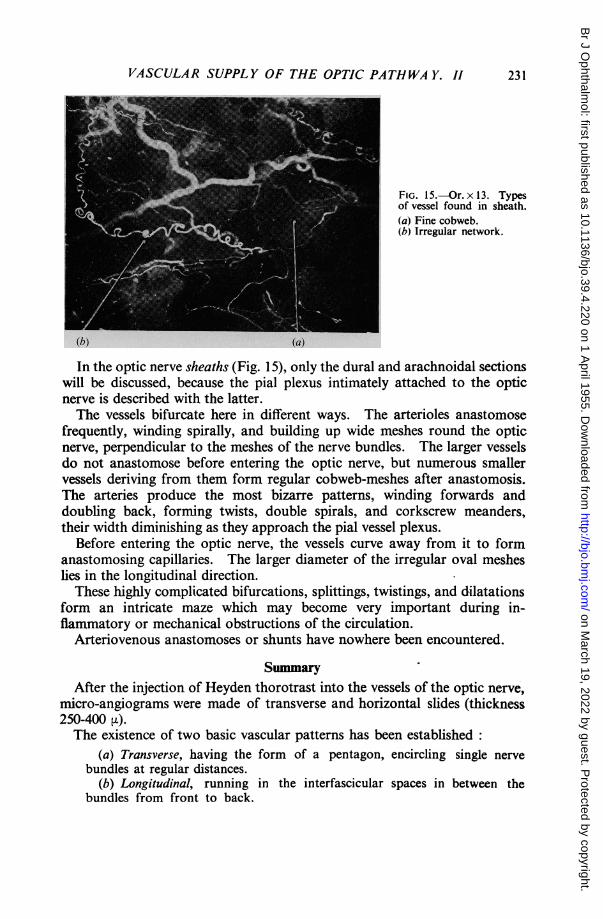
FIG. 15.-Or. x 13. Typesof vessel found in sheath.(a) Fine cobweb.(b) Irregular network.
In the optic nerve sheaths (Fig. 15), only the dural and arachnoidal sectionswill be discussed, because the pial plexus intimately attached to the opticnerve is described with the latter.
T'he vessels bifurcate here in different ways. The arterioles anastomosefrequently, winding spirally, and building up wide meshes round the opticnerve, perpendicular to the meshes of the nerve bundles. The larger vesselsdo not anastomose before entering the optic nerve, but numerous smallervessels deriving from them form regular cobweb-meshes after anastomosis.T'he arteries produce the most bizarre patterns, winding forwards anddoubling back, forming twists, double spirals, and corkscrew meanders,their width diminishing as they approach the pial vessel plexus.
Before entering the optic nerve, the vessels curve away from it to formanastomosing capillaries. The larger diameter of the. irregular oval mesheslies in the longitudinal direction.These highly complicated bifurcations, splittings, twistings, and dilatations
form an intricate maze which may become very important during in-flammatory or mechanical obstructions of the circulation.
Arteriovenous anastomoses or shunts have nowhere been encountered.
SuimmaryAfter the injection of Heyden thorotrast into the vessels of the optic nerve',
micro-angiograms were made of transverse and horizontal slides (thickness250-400 4L)The existence of two basic vascular patterns has been established
(a) Transverse, having the form of a pentagon, encircling single nervebundles at regular distances.
(b) Longitudinal, running in the interfascicular spaces in between thebundles from front to back.
231
on March 19, 2022 by guest. P
rotected by copyright.http://bjo.bm
j.com/
Br J O
phthalmol: first published as 10.1136/bjo.39.4.220 on 1 A
pril 1955. Dow
nloaded from

J. FRAN(O0S, A. NEETENS, AND J. M. COLLETTE
The latter pattern builds up the circular pentagons. Collateral vesselsbranching off from these two vascular units create an apparently inextricablecapillary meshwork. All the vessels contributing to the vascularization ofthe optic nerve anastomose in a very intimate manner.The venous blood returns chiefly through the central retinal vein.In the optic nerve-sheath, where special forms of vessels may be observed,
the capillary network is composed of fine cobweb-like formations and largeirregular meshes.
REFERENCESBARCLAY, A. E. (1951). " Micro-arteriography ". Blackwell, Oxfard.BEHR, C. (1935). v. Graefes Arch. Ophthal., 134, 227.BELLMAN, S. (1953). Acta radiol. (Stockh.), SuppI. 102.
and ENGSTROM, A. (1952). Ibid., 38, 98.BOHATYRTSCHUK, F. (1944). Ibid., 25, 351.BRASSEUR, H. (1945). " Les rayons X et leurs applications ". Desoer, Liege.CoLLErE, J. M. (1953). J. belge Radiol., 36, 293.EISLER, P. (1930). "Kurzes Handbuch der Ophthalmologie ", vol. 1, ed. F. Schieck and A.
Bruckner. Springer, Berlin.ENGSTROM, A. (1949). Acta radiol. (Stockh.), 31, 503.
(1951). Ibid., 36, 305.and WEGSTEDT, L. (1951). Ibid., 35, 345.
FAZIo, C., and FARINA, P. (1940). Riv. oto-neuro-oftal., 17, 38.FRAN;OIS, J., and NEETENS, A. (1954). British Journal of Ophthalmology, 38, 472.LEBER, T. (1903). In "Graefe Saemisch-Handbuch der gesamten Augenheilkunde ", 2nd ed.,
vol. 2., abt. 2. Engelmann, Leipzig.MAGITOT, A. (1908). "Contribution i I etude de la circulation arterielle et lymphatique du nerf
optique et du chiasma ", vol. 2, p. 3. These de Paris, No. 228.TIRMAN, W. S., CAYLOR, C. E., BANKER, H. W., and CAYLOR, T. E. (1951). Radiology, 57, 70.WOLFF, E. (1948). " The Anatomy of the Eye and Orbit ", 3rd ed. Lewis, London.
232
on March 19, 2022 by guest. P
rotected by copyright.http://bjo.bm
j.com/
Br J O
phthalmol: first published as 10.1136/bjo.39.4.220 on 1 A
pril 1955. Dow
nloaded from


![Erythropoietin-mediated activation of aquaporin-4 channel ... · Water effluxes via glial-vascular pathway or Bglymphatic pathway^ [13] by modulating AQP4 channel is ... Hydrocephalus](https://static.fdocuments.us/doc/165x107/5d1a5bd488c993b3668dec77/erythropoietin-mediated-activation-of-aquaporin-4-channel-water-effluxes.jpg)


