Variant Management for Software Applications for Public ...
136
Variant Management for Software Applications for Public Administrations Gryzlak, Karin July 22, 2016 Prof. Dr. Knut Hinkelmann Master of Science in Business Information Systems Master Thesis
Transcript of Variant Management for Software Applications for Public ...
Variant Management for Software Applications for
Public Administrations
Gryzlak, Karin
July 22, 2016
Prof. Dr. Knut Hinkelmann
Master of Science in Business Information Systems Master Thesis

Author
Karin Gryzlak
Supervisor
Prof. Dr. Knut Hinkelmann
FHNW
Abstract
July 22, 2016 I
Abstract
Nowadays, software is getting more complex due to upcoming requirements from customers. It
is therefore necessary to handle the variants of a software system’s different components and to
know what customer uses which component and/or variant. In the area of public
administrations, the requirements differ as they are not just influenced by the needs of a
company but also by laws and regulations.
The purpose of variant management is to handle customer-specific parts for different customers
within one system. In order to handle such variants, different concepts can be applied. However,
although variant management can be used for every kind of software, it needs to be adapted to
the specific case of software for public administrations.
This research thesis illustrates how feature trees can be extended and adapted to represent the
elements of the specific case of variant management for public administration software. The
starting point are software product lines (SPL) with the concept of feature trees for describing a
system. Adding elements like influencers or rules to the concept of feature trees and extending it
with new relations such as requires shows that it is possible to model variants in an area with
specific requirements.
Modelling a system with the extended feature model allows finding and retrieving variants for
individual customers. A model based on feature trees for an application used in public
administrations with all relevant features and relations is developed. The investigated
application is a message based register with data about residents on cantonal level. The
development is based on results of interviews with employees of a company that develops
software for public administrations. In order to evaluate the model, actual results of queries are
compared to expected results. Queries are used to retrieve information from the modelled
application based on a specific syntax. To find out if the approach could be applicable and
useful in practice, some of the practitioners are consulted.
Keywords: Variant Management, Public Administration, Software Product Line, SPL, Feature
Tree, Feature Modelling, ADOxx.

Acknowledgements
July 22, 2016 II
Acknowledgements
I would like to thank all people who accompanied and supported me during this thesis in many
ways.
First, I would like to thank my supervisor Prof. Dr. Knut Hinkelmann for his support, the time
taken for answering all my questions and providing valuable inputs.
I express my thanks to Ben Lammel who trained me and provided his assistance in using
ADOxx. This was a good help to develop the graphical model in a representative way.
Many thanks also go to the Bedag team members who have taken their time to discuss questions
and also the results of this study. Especially Regula who was there to provide every detail I
needed to know.
I also would like to thank my working colleagues as they gave me the opportunity to take days
off, even though there were many things going on. Also, they tolerated me in the office working
on my thesis at my days off and made it a pleasant working environment.
Finally, I want to thank my family and friends for being kind to me and for their understanding
when I was often occupied writing my thesis.
Table of Contents
July 22, 2016 IV
Table of Contents
Abstract .................................................................................................................................... I!
Acknowledgements ....................................................................................................................... II!
Statement of Authenticity ............................................................................................................ III!
Table of Contents ........................................................................................................................ IV!
1.! Introduction ............................................................................................................................ 1!
1.1! Research Problem ................................................................................................................. 1!
1.2! Application Scenario ............................................................................................................ 2!
1.3! Thesis Statement .................................................................................................................. 3!
1.4! Research Questions and Objectives ..................................................................................... 4!
1.5! Limitations ........................................................................................................................... 5!
1.6! Structure of the Paper and Thesis Map ................................................................................ 5!
2.! Literature Review ................................................................................................................... 8!
2.1! Variant Management in Public Administration ................................................................... 8!
2.2! Variants ................................................................................................................................ 9!
2.3! Variant Management .......................................................................................................... 10!
2.3.1! Challenges and Goals ...................................................................................................... 11!
2.3.2! Reusability ...................................................................................................................... 12!
2.3.3! Maintenance .................................................................................................................... 14!
2.4! Concepts for Variant Management .................................................................................... 15!
2.4.1! Software Product Lines ................................................................................................... 15!
2.4.2! Feature Trees/Feature Models ......................................................................................... 18!
2.4.3! Configuration Management ............................................................................................ 21!
2.4.4! Requirements Engineering and Modelling ...................................................................... 22!
2.5! Summary ............................................................................................................................ 25!
3.! Research Method .................................................................................................................. 26!
3.1! Introduction ........................................................................................................................ 26!
Table of Contents
July 22, 2016 V
3.2! Research Onion .................................................................................................................. 26!
3.3! Research Philosophy .......................................................................................................... 26!
3.4! Research Approach ............................................................................................................ 27!
3.5! Research Strategy ............................................................................................................... 28!
3.6! Research Choices ............................................................................................................... 31!
3.7! Time Horizons .................................................................................................................... 32!
3.8! Data Collection and Data Analysis .................................................................................... 32!
3.9! Research Design ................................................................................................................. 33!
3.9.1! Awareness of Problem .................................................................................................... 34!
3.9.2! Suggestion ...................................................................................................................... 35!
3.9.3! Development ................................................................................................................... 36!
3.9.4! Conclusion ...................................................................................................................... 37!
3.10! Summary .......................................................................................................................... 37!
4.! Problem Awareness .............................................................................................................. 38!
4.1! Requirements Analysis ....................................................................................................... 38!
4.1.1! Interview Questions ........................................................................................................ 39!
4.1.2! Interview Partners ........................................................................................................... 39!
4.1.3! Interview Results ............................................................................................................. 41!
4.2! Competency Questions ....................................................................................................... 42!
4.2.1! Motivation Scenarios ...................................................................................................... 43!
4.2.2! Problems in Changing Requirements .............................................................................. 49!
4.3! Variants and Influencers .................................................................................................... 49!
4.3.1! Differences in Variants/Variability ................................................................................. 51!
4.4! Variant Management Methods ........................................................................................... 53!
4.5! Summary ............................................................................................................................ 57!
5.! Suggestion ............................................................................................................................ 58!
5.1! Introduction of RREG Software ......................................................................................... 58!
5.2! Definition ........................................................................................................................... 58!
Table of Contents
July 22, 2016 VI
5.3! Conceptual Model .............................................................................................................. 61!
5.4! Conceptual Model with Relationships ............................................................................... 68!
5.5! Conceptual Model with Relationships and Influencers ..................................................... 71!
5.6! Summary ............................................................................................................................ 73!
6.! Development ........................................................................................................................ 74!
6.1! Introduction to ADOxx Meta-Modelling Approach .......................................................... 74!
6.2! Graphical Model ................................................................................................................. 77!
6.3! Summary ............................................................................................................................ 82!
7.! Evaluation ............................................................................................................................ 83!
7.1! Technical Evaluation .......................................................................................................... 83!
7.1.1! Instances for Motivation Scenario 1 ............................................................................... 85!
7.1.2! Instances for Motivation Scenario 2 ............................................................................... 91!
7.1.3! Instances for Motivation Scenario 3 ............................................................................... 96!
7.1.4! Instances for Motivation Scenario 4 ............................................................................... 97!
7.2! User Evaluation .................................................................................................................. 98!
7.3! Summary .......................................................................................................................... 100!
8.! Conclusion and Future Work ............................................................................................. 101!
8.1! Conclusion ........................................................................................................................ 101!
8.2! Contribution ..................................................................................................................... 103!
8.3! Future Work ..................................................................................................................... 104!
Bibliography .............................................................................................................................. 105!
Abbreviations ............................................................................................................................ 112!
List of Figures / Tables .............................................................................................................. 113!
Figures ............................................................................................................................... 113!
Tables ............................................................................................................................... 116!
Appendices ............................................................................................................................... 117!
1. Introduction
July 22, 2016 1
1. Introduction
Today, products arise in many different variants in order to satisfy all customer needs. To
satisfy these needs, companies have to be aware of the fact that product variants exist, of how
they evolve and of the corresponding problems (Kunz, 2005). Mastering complexity in service
oriented enterprise architectures and accompanying dependencies requires extensive knowledge
from business and IT departments.
1.1 Research Problem
Variant management is a well-known topic in different industry areas. In the area of software
development and management it becomes more and more important, because of service
orientation and the use of cloud services software will be split up more into logical parts.
Splitting software up into logical components, allows the developers to reuse common parts for
different customers without developing a whole new application. Generally, there is no clear
definition of what a variant is and how variants differ from each other. For every case it is
necessary to define the variants among the components of a software application or a process
model. This includes internal variability caused by the design of the product and external
variability based on market demand (Buchholz & Souren, 2008). Variant management is
required in order to track what variants are in use at which point and what the relations between
two variants are.
In the area of public administrations, the methods (mostly reference models) for variant
handling are mainly based on processes management in the area of electronic Government.
Laws and regulations have a vast impact on defining variants and corresponding changes
(Ciaghi, Villafiorita, & Mattioli, 2009). Today, the handling of variants of features in software
is not defined specifically enough. However, there are different methods for handling variants
and to reuse software parts. Software product lines (SPL) are one of them. In this approach,
possible variants of the software are considered right from the beginning of the development
process. The software is divided into components, which allows to generate different variants of
the software (Pohl, Böckle, & van der Linden, 2005). Feature trees are one of the best known
approaches in representing variants and handling variability (Manz, Stupperich, & Reichert,
2013). Relations between features (types are: "and", "alternative", "or", "mandatory" and
"optional") are defined, which includes dependency relationships (constraints). However, these
relations and the defined features do not fully cover the requirements of variant management for
software for public administration. Thus, they need to be extended and adapted to this specific
area.
1. Introduction
July 22, 2016 2
For example, requirement engineering (RE) is such an extension. RE is about gathering and
documenting information about a system, i.e. its working principles, involved parties, etc. Such
a documentation allows tracking changes in requirements, which, in the case of public
administrations, are mostly based on laws or regulations and therefore have a significant impact
on software (Yu, 1997). A combination of variant management, RE, and already known,
process-based models for public administration software has not been defined so far.
Value of Solution
Requirements from product managers and product engineers as well as on requirements from
law and regulations led to a search for a well-defined method to represent and handle variants
and variability in software for public administrations. This could be achieved by combining
existing models with concepts like feature trees or software product lines and requirements
engineering.
Also, how features are handled in case a requirement changes from top down (e.g. federal
regulations that influence cantonal regulations) and what the result of such a change is or can
be, will have a significant influence on the identification of a suitable model representation.
Considering the definition and the handling of variants in public administration software, this
thesis aims at filling the gap between theoretical ideas and practical usefulness. In more detail,
the result of this thesis needs to be understandable and usable by practitioners in a well-adapted
way. To reach this aim the model representation is evaluated in cooperation with the
practitioners who work in the respective area.
1.2 Application Scenario
This thesis was carried out in cooperation with Bedag Informatik AG (hereafter referred to as
“Bedag”), specifically its department for software development and the respective product
managers. Bedag aims for a consistent management of the different variants of its cantonal
software applications and their architectures. This goal was the foundation of the formulation of
the thesis statement and the research questions. As it is a practical problem, this thesis combines
practical aspects with scientific research.
By the day the thesis started, Bedag’s application portfolio comprised several applications,
which, however, were operated monolithically. This means applications are always tested and
provided to the customer as a whole and not just the changed modules. In the case at hand,
variants and dependencies among these variants need to be managed in software applications for
public administrations within a federal system. A federal system includes cantons and
1. Introduction
July 22, 2016 3
municipalities with its different legislations and the superior nationwide laws. I.e., public
administrations of different cantons or municipalities provide almost the same services to their
customers-, but with different processes based on different legal foundations and on different
responsibilities. An example from this area are taxes: every public administration (municipality,
canton and state) needs to handle taxes, but not every entity needs to cover the same services. In
some cantons, the handling of the tax register is located on the cantonal level, whereas it is
handled on municipality level in other cantons. The corresponding software applications have a
lot in common, but do also differ in certain aspects. This leads to the problem that there are non-
reusable program artefacts within the different applications. Therefore, Bedag plans to split
these complex business applications into small, logically connected components. Those
software components, one of which can then be a part of several applications, will be separate
services. Such a service will be available through a standardised interface and provide one
specific, defined function. For example, consider a generic printing service that can be used by
various applications.
The goals of this approach in handling variants are the elimination of redundancies, the increase
of quality through cooperation, and a consistent information model. To reduce redundancies in
data, a consequent master data management is useful. Data may only be entered (or altered) by
the data owner, whereas others have only reading access.
1.3 Thesis Statement
According to Hofstee (2006, p.19), a ‘thesis’ is a hypothesis, an unproven statement about
something. A statement can be argued with evidence or can be tested and therefore the
researcher has to take a clear position (Hofstee, 2006, p.20). Starting from the practical situation
described above, the thesis statement was derived. It includes the requirements regarding
software applications and the customers’ needs, as well as theoretical aspects such as the
management of variants and the corresponding requirements. The thesis statement is defined as
follows:
A description and graphical modelling of variants, including their requirements and
interdependencies, of software for public administrations in Switzerland support
management of software variants.
1. Introduction
July 22, 2016 4
1.4 Research Questions and Objectives
To prove or dismiss the thesis statement, the following research questions are formulated.
According to the defined research questions, the research aims to fulfil the following objectives.
Research Question 1: What are the requirements for a variant management system in the
application area?
A real world problem is analysed in order to establish a common understanding of the variants,
the related problems, and the questions to be answered in order to handle such variants. The
requirements are identified based on current literature and on interviews with software engineers
working in the field.
Research Question 2: How do variants differ from each other?
Criteria how a variant can be differentiated from another are identified. It is determined what
requirements have to be fulfilled in order to distinguish discrete variants of a specific software
component.
Research Question 3: Which variant management methods exist and can be applied to the
problem at hand?
Providing an overview of the existing methods of handling variant management is the third
objective of this research. The methods are described, and it is discussed which aspects from the
different methods can be employed in order to identify a valid solution to improve state-of-the-
art, monolithic software applications.
Research Question 4: What influencers do exist and what is their impact on variant
management?
Define influences on changing and new variants in the specific area of software for public
administrations. Evaluating the impact the influencers have on the already existing variants and
the variant management, based on information obtained from a real world problem.
Research Question 5: How can variants and influencers be described?
A conceptual model for managing variants using the questions of competency from research
question 1 regarding the variants and influencers related to software applications for public
administration is derived. This includes also an approach to model requirements leading to a
specific variant and the corresponding relationships. The proposed solution is then suggested to
1. Introduction
July 22, 2016 5
the interview partners in order for them to evaluate it in their daily work with variants.
Afterwards, the model is adapted based on the focus group’s feedback.
Research Question 6: How shall a modelling language be defined in order to achieve a simple
representation of the variants?
The modelling language is applied to a real world problem for validation purposes, which are
conducted by the product managers, the software engineers and the author of this thesis.
1.5 Limitations
Regarding the scope of this thesis, the focus lies on software applications and variants in
particular. The application field includes only software for public administration in
Switzerland’s hierarchical/federal governmental system with its cantonal differences.
1.6 Structure of the Paper and Thesis Map
To answer the research question, the design science research approach is selected, which is
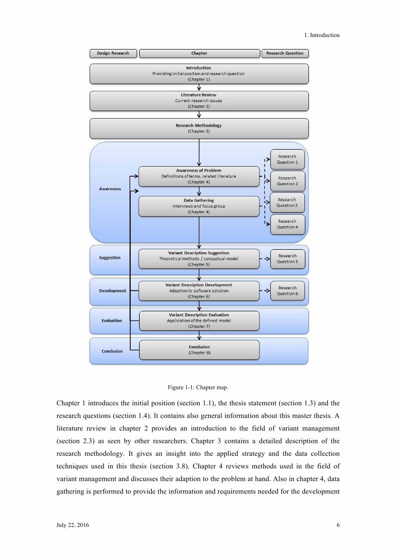
reflected by the thesis map shown in Figure 1-1. This approach contains five steps: awareness,
suggestion, development, evaluation and conclusion (Kuechler & Vaishnavi, 2008). Each step is
linked to the chapters of this thesis and the research questions.
1. Introduction
July 22, 2016 6
Figure 1-1: Chapter map.
Chapter 1 introduces the initial position (section 1.1), the thesis statement (section 1.3) and the
research questions (section 1.4). It contains also general information about this master thesis. A
literature review in chapter 2 provides an introduction to the field of variant management
(section 2.3) as seen by other researchers. Chapter 3 contains a detailed description of the
research methodology. It gives an insight into the applied strategy and the data collection
techniques used in this thesis (section 3.8). Chapter 4 reviews methods used in the field of
variant management and discusses their adaption to the problem at hand. Also in chapter 4, data
gathering is performed to provide the information and requirements needed for the development

1. Introduction
July 22, 2016 7
of a suitable variant description methodology. Chapters 5, 6 and 7 deal with the suggestion,
development and evaluation of the variant description based on real-world data. The conclusion
and outlook (chapter 8) summarise all research results of this thesis and reflects upon the
research process and the findings.
2. Literature Review
July 22, 2016 8
2. Literature Review
In chapter 2, basic information is collected, which can then be used for the further research.
First, approaches to variant management in Public Administrations are introduced, since the
research focuses on this area. Second, general terms and definitions are described to reach a
consistent understanding of the topic of variant management. Subsequently, an overview of the
current research issues in the area of variant management is given. The first part contains
information about what a variant is and how variant management is defined. Challenges of
handling the variants, reusability and maintenance are described within the definition of variant
management, and software product lines (SPL) and the concept of feature trees are introduced.
Finally, configuration management and requirements engineering are described, including more
information about mapping features to code assets and how to model requirements.
2.1 Variant Management in Public Administration
Municipalities and cantons offer almost the same services but do have deviations based on the
different laws, regulations or processes. Within software, a huge amount of different variants
can arise and the handling of these is difficult, mainly because it has to be exactly known which
feature belongs to what customer and how the individual features are related with each other.
Most aspects of variant management in public administrations that can be found in literature
refer to eGov-solutions (electronic Government) and corresponding processes and reference
models. Local communities and cantons have a lot of services based on legal requirements.
These services do mainly follow the same structure and are therefore suited for reference
models (Hinkelmann, Thönssen, & Probst, 2005). These models are generally admitted and
need to be abstracted according to the specific variants in different administrations. A reason for
defining variants can be regulations on local, cantonal or governmental basis and need to be
adapted for every case (Becker, Algermissen, Delfmann, & Niehaves, 2003). The main goal for
process management in this case is the reusability of the process which facilitates cost
reductions (Becker, Algermissen, Delfmann, & Niehaves, 2005).
In order to build basic reference models, specific processes are investigated in different
municipalities or other public administrations with the same responsibility, and afterwards
generalised. Common features in the processes are merged to an overall basic reference model
with alternative intersections or are generalised through the use of abstract process steps
(Hinkelmann et al., 2005).
2. Literature Review
July 22, 2016 9
Processes in public administrations are defined and regulated by laws and conditions.
Introduction of law changes leads to the fact that any implementation of a to-be process requires
a parallel action on redesigning a process. Laws and regulations therefore need to be considered
as a constraint in a model. Because of this link between models and laws, further issues related
to maintainability of the models over time do arise. Every change in a law directly influences
the models, and still it is necessary to guarantee coherency of the models (Ciaghi et al., 2009).
As the regulations and laws differ in cantons or also municipalities, it is unlikely that a universal
solution exists and can be used for every public administration. For software in use it is
necessary to cover a variety of business domains including domain-specific tasks and business
processes, for which specific solutions are required. All information and data within this
software can be, generally, divided into two categories: common and specific. This is done for
the reference model in the processes and needs to be done for software, too (Klarin &
Mladenović, 2012). As typically changes are given by law, traceability is also important to
consider. It is essential to identify and to trace what needs to be changed in order to cover the
conditions given by law (Ciaghi et al., 2009).
Variant Management is done also in public administrations, but the general models are not
specific enough for handling variants that are mostly influenced by laws and regulations. In
order to establish an understanding of variants and the concepts available for handling them, the
next Sections will introduce such concepts.
2.2 Variants
According to Voigt (2013), a variant is a final product, which differs in features, but does not
differ or differs only slightly in terms of general aspects. According to Buchholz & Souren
(2008), the term variant is often not defined precisely. They define what differentiates variants
from each other (type, shape, function), but they do not define what "slightly different" means.
Buchholz & Souren (2008) define characteristics, e.g. what is compared, what is the difference
of the objects and how much do they differentiate. These characteristics are needed in order to
give a definition of the term variant.
In the field of software engineering, different characteristics of a product are called a variant
(Grosse-Rhode, Kleinod, & Mann, 2007). The main reason to call a specific asset a variant is
the fact, that the asset has been derived from an already existing asset and that it has
stakeholder-relevant properties which differ from other variants derived from the same asset
(Böckle, Knauber, Pohl, & Schmid, 2004). In addition to defining the term variant, it is also
important to define what the difference between a variant and a version is. Versions refer to a
single asset (i.e., a single variant) at a different point in time. Normally they are identified by
2. Literature Review
July 22, 2016 10
numbers or some sort of labels in order to differentiate one version from another (Beuche &
Dalgarno, 2008).
Variants are normally defined by a company. The company has to think ahead, understand and
manage the requirements of the customers in order to handle variants. Customer requirements
cause so-called externally driven diversity, which then leads to an internal diversity, as the
requirements have to be implemented. Other external drivers include market influences, laws,
norms and guidelines. Internally driven diversity is based on a company's product portfolio,
which may contain different variants. In general, it is not easy to differentiate internal and
external drivers because they influence each other (Kesper, 2012, p.28).
External variability comprises the product variability seen by the customer. This includes the
variability which is needed to define a customer-specific product (Rosenmüller, Siegmund,
Thüm, & Saake, 2011). External variability is normally included in the requirements definition
of a component. In contrast, internal variability cannot be seen by the customer, but often cannot
be avoided, since it typically arises from technical reasons (e.g. different hardware platforms)
and is normally documented in corresponding artefacts (Manz et al., 2013).
These concepts related to variants are also used in the area of software for public
administrations. There, variants are often driven by external diversity, because laws and
regulations have a big influence on how software needs to be designed. Internal diversity also
arises as there are technical requirements, which lead to additional variants that are not
explicitly demanded by a customer.
2.3 Variant Management
The term variant management is commonly used in the area of logistics and production and
refers to a holistic approach in handling variants of products in the production line (ROI
Management Consulting AG, 2015). It is not only used in design engineering but also in the
area of software engineering (Manz et al., 2013).
Product variants, whether differing by function or parameter values that drive functional
behaviour, have a significant amount of commonalities that must be leveraged to lessen
complexity across variants (PTC Integrity Business Unit Locations, 2012).
Internal and external variability normally have a positive correlation, but the ratio of internal
and external variants relies on the product design. A superior goal of variant management is to
influence this ratio positively using suitable concepts to design the products in order to
2. Literature Review
July 22, 2016 11
maximise the share of external variability and minimise the share of internal variability (Kesper,
2012).
It is important to know how variants can be modelled and managed in general and for the
specific case of software for public administration. The following subsection will provide an
overview on challenges and goals of variant management, as well as on reusability and
maintenance of software. The three parts, avoiding, control and reduction of variants, are
essential in every area software is developed. Software parts should be reused and well
maintained, and in addition tests should also be confined to the changed parts of a system.
2.3.1 Challenges and Goals
According to Kesper (2012), variant management includes all activities to avoid, control and
reduce product and component variants.
• Avoidance of variants: aims at preventing product and component variants from the
beginning and still being able to fulfil all (current and future) customer requirements.
• Control of variants: aims at handling all product and component variants through the
whole value-added chain and to do so as efficiently as possible.
• Reduction of variants: aims at eliminating current product variants but without
compromising the customer requirements.
These three basic strategies can, according to Kersten (2002, p.7), be related to internal or
external variability. In order to avoid too much variability, a precise definition of the products to
be offered based on market demand (external variability) has to be established and a suitable
design of the product (internal variability) exploiting technological options has to be performed.
It is a challenge to define the number of different variants in one product group. But it is also
essential to define all variants carefully (Buchholz & Souren, 2008). Without the definition and
the handling of the variants and their commonalities, duplicates can occur, which can lead to
exponential growth of the number of artefacts. This, in turn, leads to a high usage of resources,
and therefore high costs for developing and maintaining each variant. Furthermore, once
duplicated, the traceability of the original variant gets lost (Buchholz & Souren, 2008).
A goal in variant management is the reusability of given processes and artefacts. According to
Kubica (2007, p.4) it is not just the source code or the software itself that can be reused. I
addition, also requirements, software design methods or knowledge from employees should be
used several times if applicable. According to Balzert (1998, cited in (Kubica, 2007)) all kinds
of reusability have the same goals, which are defined as follows:
2. Literature Review
July 22, 2016 12
• significant increase of productivity
• improved quality of products
• shorter development time
• cost reductions
In general, Kesper (2012) defines positive effects of the organisation’s goal to have the
possibility to fulfil demands on an individual basis. This leads to a differentiation from other
competitors in the same industry. But in order to actually realise a competitive advantage, the
additional costs have to be covered by the price such an individualized product can reach on the
market. If more variability is provided, also more complexity arises. The development and
maintenance of such software with a modular architecture and individualized components
generates higher cost. Therefore, typically an economic middle course is pursued (Böllert,
2001).
Further development includes permanent changes in software and products. Taking care of the
changes in release planning and artefact evolution over time is an important task. In order to
handle this challenge, change management and variant configurations need to be unified (Manz
et al., 2013).
According to Manz et al. (2013), by now an artefact-independent, standardized variability
interface for existing tools is needed for integrated industrial usage. This leads to the fact that
there is insufficient tool integration for an integrated feature model (compact representation, see
also section 2.4.2). The configuration of artefact types and involved variability techniques
require specialised connectors between the feature model and the artefacts. These configurations
are complex and need to be integrated into the feature model. However, with the right
configuration, invalid variants can be successfully avoided.
2.3.2 Reusability
A goal in variant management is to integrate the reusability of a variant into the development
process of the software in order to reach the goals mentioned in the section before. This should
be done from the beginning of the development process in order to reach general goals of
software development like cost reduction and improved quality (Kubica, 2007, p.9). Thereby,
the process of product engineering can be accelerated, which in turn also reduces the
development time and therefore the time to market (Böllert, 2001). Reusable software artefacts
are considered as a core asset. Therefore, artefacts created during the software development
process are often reused by more than one product. The efficiency of reusing artefacts is
relevant with respect to the success of a product line (Fazal-E-Amin, Mahmood, & Oxley,
2. Literature Review
July 22, 2016 13
2010). Reusability has turned into a productive tool for software development as it helps to
reduce time, cost and work required for software development (AL-Badareen, Selamat, & Jabar,
2011).
Reusability is defined as the degree to which an item can be reused. With regard to software it is
the ability to use parts of a system in other systems (Mccall, Richards, & Walters, 1977). Cost
and effort in maintaining a system can be reduced because the shared software parts need to be
maintained just once. Therefore, high quality systems can be developed faster with better cost-
efficiency (Böllert, 2001).
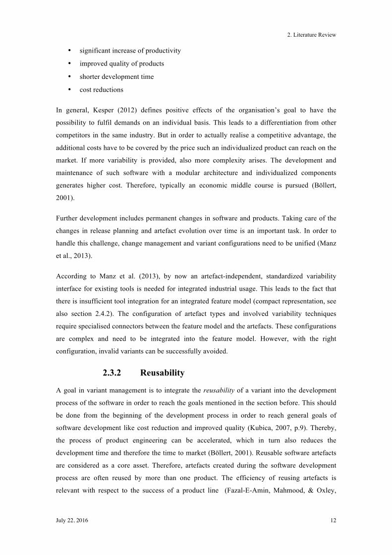
Ilyas, Abbas, & Saleem (2013) define a reusability process that helps to yield actual benefits in
form of time, cost and general effort savings. This RESAD framework divides the reusability
life cycle into three stages: extraction of reusable components, reusable components storage,
and reusable components deployment (cf. Figure 2-1).
Figure 2-1: RESAD framework (Ilyas et al., 2013).
For each step, certain criteria are defined that need to be fulfilled by the components before the
next stage of the lifecycle can be entered. If a component fulfils all required criteria, it has to be,
after the classification process is done, stored in a reusable repository from where it can be
retrieved for reuse purposes. The reusable repository facilitates easy searching and fetching of
components. After components are fetched, their suitability for a new system’s requirements is
assessed. If a component satisfies this requirements, it is adopted and a Pre-Adopt Test is
carried out in order to obtain a final selection decision (AL-Badareen et al., 2011). Based on the
criteria defined for every stage, true benefits regarding time and cost reduction as well as an
2. Literature Review
July 22, 2016 14
increase of productivity and quality of the software development process are anticipated (Ilyas
et al., 2013). The concept of reusability is required in every case where software is developed
for more than a single customer and/or where a software contains differentiated parts.
2.3.3 Maintenance
Traditionally, maintenance is defined as the modifications carried out after the delivery of a
system. It includes fault corrections, the improvement of performance or other attributes, or
adaptions of the product to a changed environment (AL-Badareen et al., 2011). As it has already
been described in section 2.3.2, reusability and maintenance are linked with each other because
of their mutual influences.
Böllert (2001) defines maintenance in the context of software product lines as the extension of
software with new features to fulfil new requirements. With the addition of such new features,
also the variability increases and with higher variability there are more potential customers, who
can use one of the product variants of the product line. This is because the amount of different
products arises.
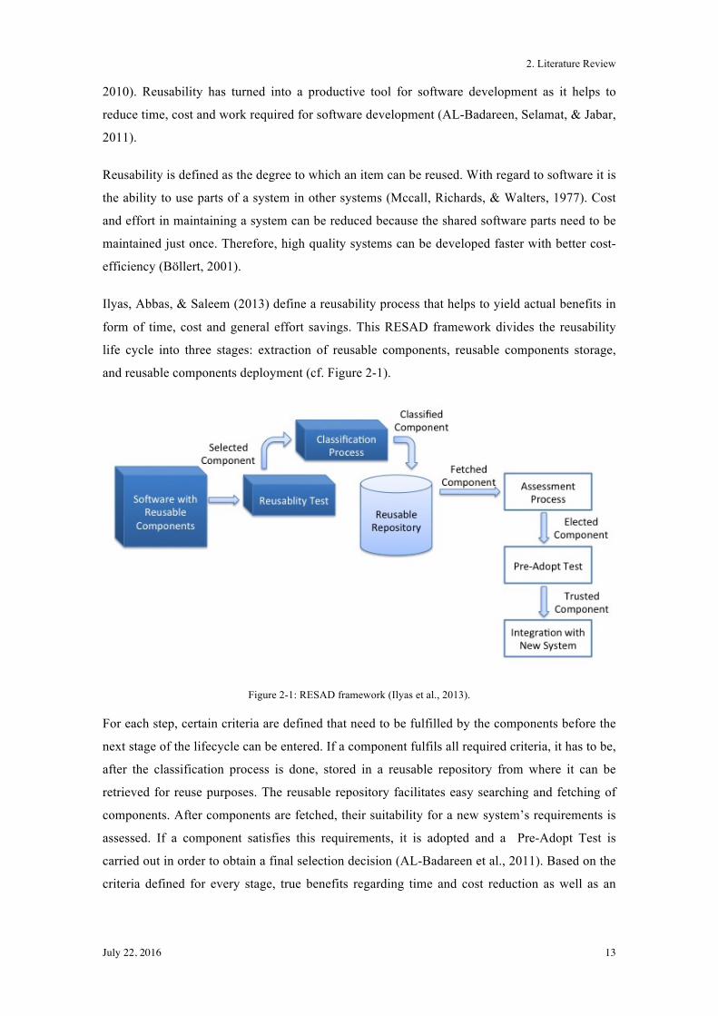
In their paper, Al-Badareen et al. (2011) show a software maintenance process that is suitable
for handling complex modifications associated with maintenance. This process is shown in
Figure 2-2.
Figure 2-2: Software maintenance process (Al-Badareen et al., 2011).
The process starts with the understanding of the system, because it is essential to understand the
system functions and their relationships before modifications are planned and applied. The
second step is the identification of required modifications to correct, enhance or adapt the
system. In the system modification step (step three) these identified functions of the system are
changed or corrected. The last step is the testing phase in which the modifications are evaluated.
Only the adapted parts are tested, whereby additionally also possible side effects on other
2. Literature Review
July 22, 2016 15
functions are analysed (Al-Badareen et al., 2011). Based on test results, additional modification
steps are executed and the results retested again until the initially defined changes are
implemented as required.
A suitable documentation of a system is an important contribution to ensure good
maintainability. Such documentation should provide comprehensive, clear and concise
information about the system. It is important to improve software development and to have a
functional maintenance process, as both, software development and the maintenance process,
contain information about the software functions and its relationships. The understanding of the
system is directly influenced by the quality of the documentation. All relevant information
needs to be available for developers at every level and has to be meaningful (Al-Badareen et al.,
2011).
2.4 Concepts for Variant Management
There are several concepts described in literature to model variants and manage them, which
can be used as a basis for variant management for software for public administration. The
following subsections describe the concept of software product lines, feature trees as a
modelling aspect, configuration management for implementation, and requirements engineering
and modelling for handling customer requirements.
2.4.1 Software Product Lines
Software product lines (SPL) define an approach in software development to fulfil requirements
in a specific domain. According to the Software Engineering Institute, which introduced SPL, it
is defined as:
A software product line is a set of software-intensive systems that share a common, managed set of features satisfying the specific needs of a particular market segment or mission and that are developed from a common set of core assets in a prescribed way (Software Engineering Institute Carnegie Melon University, 2012).
There is much more effort required to develop a software product line than is to develop a single
product only. According to Kubica (2007, p.34), it is worth to use SPLs if the product is planned
to be used multiple times in different variants. Software product line development is based on
planned, systematic (and therefore proactive) reuse of software artefacts (Pohl & Metzger,
2008).
Thus, the main focus in SPLs is the systematic reuse of core assets, where a distinction of
"development for reuse” and “development with reuse" needs to be made (van den Linden,
Schmid, & Rommes, 2007). Development with reuse refers to application engineering, which
2. Literature Review
July 22, 2016 16
builds the final product on top of the product line infrastructure. As software reusability is one
of the key features, it renders the assessment of core assets more important, because the success
of a product line is based on the efficient reuse of core assets (Fazal-E-Amin et al., 2010).
According to Böckle et al. (2004) there are two main principles to be taken into account if a
software intensive product line is developed:
• Description of the variability of the product line
• Separating domain and application engineering
In order to balance costs and benefits, and not to just spend money on planning, products, that
will be reused need to be defined in advance, including their main characteristics (i.e. their
features) and the variability of these characteristics.
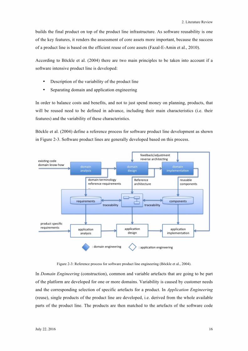
Böckle et al. (2004) define a reference process for software product line development as shown
in Figure 2-3. Software product lines are generally developed based on this process.
Figure 2-3: Reference process for software product line engineering (Böckle et al., 2004).
In Domain Engineering (construction), common and variable artefacts that are going to be part
of the platform are developed for one or more domains. Variability is caused by customer needs
and the corresponding selection of specific artefacts for a product. In Application Engineering
(reuse), single products of the product line are developed, i.e. derived from the whole available
parts of the product line. The products are then matched to the artefacts of the software code
2. Literature Review
July 22, 2016 17
such that the product-specific software development effort is minimized. Requirements,
architecture and tests provided by the platform are used, only undefined parts need to be
developed separately.
In order to ensure traceability in product line engineering, it has to be documented which
components or component parameters are used based on which requirement (Böllert, 2001).
Requirements in public administrations are often based on the legal situation and therefore have
a huge impact on the derived components and the traceability in particular. Changes in law may
be on federal level and have an influence on cantonal or municipality level, which is a special
requirement when tracing changes.
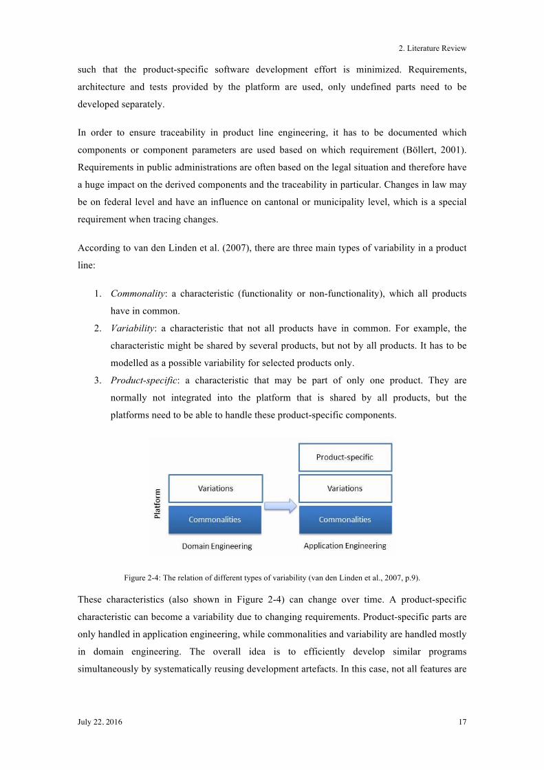
According to van den Linden et al. (2007), there are three main types of variability in a product
line:
1. Commonality: a characteristic (functionality or non-functionality), which all products
have in common.
2. Variability: a characteristic that not all products have in common. For example, the
characteristic might be shared by several products, but not by all products. It has to be
modelled as a possible variability for selected products only.
3. Product-specific: a characteristic that may be part of only one product. They are
normally not integrated into the platform that is shared by all products, but the
platforms need to be able to handle these product-specific components.
Figure 2-4: The relation of different types of variability (van den Linden et al., 2007, p.9).
These characteristics (also shown in Figure 2-4) can change over time. A product-specific
characteristic can become a variability due to changing requirements. Product-specific parts are
only handled in application engineering, while commonalities and variability are handled mostly
in domain engineering. The overall idea is to efficiently develop similar programs
simultaneously by systematically reusing development artefacts. In this case, not all features are
2. Literature Review
July 22, 2016 18
prominently visible by the user. Instead, they are defined by quality aspects or characteristics of
a software system (Kang, Cohen, Hess, Novak, & Peterson, 1990).
Böllert (2001) defines two main requirements to change a development process into a product
line: economic and technical requirements. Economic requirements include competition
pressure in a business segment. If the pressure in a segment is high and the time-to-market is
relevant to be competitive, it is mandatory to use product lines. As a technical requirement, the
domain the product is located in needs to be stable and well established. Technical requirements
need to be known and should not change during the lifetime of the system. If this is not given,
maintenance costs will increase and the costs saved by using a product line are irrelevant. In
general, product lines are not suitable for products that are still in a development phase.
2.4.2 Feature Trees/Feature Models
Structuring and visualising large and complex connections is a major part of variant
management. In order to fulfil this task, feature trees (or sometimes also known as feature
models or feature diagrams) are one of several suitable instruments. Feature trees are a common
form of variability models and can have several representations (Thüm, Kästner, Erdweg, &
Siegmund, 2011).
Feature trees or feature models are one of the best known ways of representing variants or
packages of variants. According to the name, features and their characteristics or products and
product families are displayed in a tree diagram. Feature models must have the ability to handle
the rising complexity coming along with software variants, e.g. conflicts resulting from the
combination of mutually exclusive artefacts (Manz et al., 2013).
Böckle et al. (2004) define feature modelling as follows:
A common method to handle restrictions and relations between product characteristics is feature modelling. It helps to reduce the complexity to configure a valid variant and to establish an explicit documentation of dependencies between components. […] An integrated variant management through an integrated feature model must consider several development phases, abstraction layers, and artefacts.
And with regard to products, Manz et al. (2013) point out:
While common parts are included in every product (e.g., every vehicle has an engine), variability describes different features of products (e.g., standard, sportive, classic).
Feature models are represented in a tree structure with parent-child relation between features.
With respect to SPLs it is a hierarchical representation of an SPL's features and hence captures
the variability of an SPL (Rosenmüller et al., 2011).
2. Literature Review
July 22, 2016 19
Batory (2005) defines the following; relationships between a parent (or compound) feature and
its child features (or subfeatures) as follows:
• And — all subfeatures must be selected,
• Alternative — only one subfeature can be selected out of a group of features,
• Or — one or more can be selected (n:m, one to many cardinality),
• Mandatory — features that required, and
• Optional — features that are optional.
Based on these options, features can be classified into common features and variable features.
All common features, which include the root node that is always selected, are and-features, and
not grouped. All other features are variable. Hierarchical relations in a feature model need to be
consistent. Therefore, a feature can be related only to a single superior feature or to the root
node (Böllert, 2001, p.47).
Additionally, feature trees are not grammar-free. There are often additional constraints, called
non-grammar constraints (dependency relationships). The major two are, according to (Batory,
2005), the following:
• Exclusion — choosing a feature automatically excludes a given feature list (can be uni-
or bidirectional)
• Inclusion — choosing a feature automatically includes or requires a given feature list (is
always bidirectional)
Such dependencies influence customer choices by limiting them. Since the constraints have to
be observed, customers cannot choose every combination they might like. For example, a
feature cannot have more than one inclusion-relation to a feature of a feature group with
alternative features (Böllert, 2001, p.48).
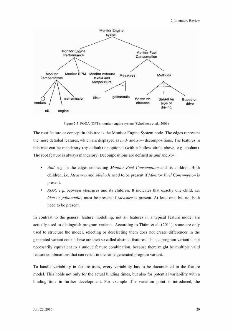
In their paper, Schobbens, Heymans, Trigaux, & Bontemps (2006) define an example of Feature
Oriented Domain Analysis (FODA) or Original Feature Tree (OFT), which is displayed in
Figure 2-5. It shows the allowed combinations of features for a family of systems intended to
monitor the engine of a car.
2. Literature Review
July 22, 2016 20
Figure 2-5: FODA (OFT): monitor engine system (Schobbens et al., 2006).
The root feature or concept in this tree is the Monitor Engine System node. The edges represent
the more detailed features, which are displayed as and- and xor- decompositions. The features in
this tree can be mandatory (by default) or optional (with a hollow circle above, e.g. coolant).
The root feature is always mandatory. Decompositions are defined as and and xor:
• And: e.g. in the edges connecting Monitor Fuel Consumption and its children. Both
children, i.e. Measures and Methods need to be present if Monitor Fuel Consumption is
present.
• XOR: e.g. between Measures and its children. It indicates that exactly one child, i.e.
l/km or gallon/mile, must be present if Measure is present. At least one, but not both
need to be present.
In contrast to the general feature modelling, not all features in a typical feature model are
actually used to distinguish program variants. According to Thüm et al. (2011), some are only
used to structure the model, selecting or deselecting them does not create differences in the
generated variant code. These are then so called abstract features. Thus, a program variant is not
necessarily equivalent to a unique feature combination, because there might be multiple valid
feature combinations that can result in the same generated program variant.
To handle variability in feature trees, every variability has to be documented in the feature
model. This holds not only for the actual binding times, but also for potential variability with a
binding time in further development. For example if a variation point is introduced, the
2. Literature Review
July 22, 2016 21
variability has to be documented even though the final characteristic might still be unknown
(Manz et al., 2013).
If product lines are implemented, variability is a huge challenge. The reference architecture is
the basis for all systems in a product line and needs to be defined in a flexible way in order to
handle all requested variants. The quality of the handling of the reference architecture is an
important quality metric. A controlled evolution of the architecture is crucial to the success of a
product line. It is a basis to efficiently evolve system variants, also based on extensive reuse
(Böckle et al., 2004, p.110f).
Software product lines with the concept of feature trees are a useful tool to address the handling
of variants in public administration software. Feature trees are not yet used in this specific area
and need to be analysed in detail and adapted to the special application area of public
administration software. However, the concepts are well known and established, which provides
a suitable basis for adapting them to new, specialized areas.
2.4.3 Configuration Management
Another important aspect of implementing different program variants is the configuration
management. There are implementation mechanisms, which are needed to map features
residing in a so-called problem space to implementation artefacts, which are part of solution
space. In the most simple case, a single feature can be mapped to a single code unit (Thüm et
al., 2011). Configuration Management is also a common technique used to manage different
versions of development artefacts, which are valid at different times. Because software evolves
over time, complexity increases and adaptions become harder to integrate (Pohl et al., 2005).
According to Bachmann & Bass (2001), the inputs of a configuration management system are
the designed variants and the variation points. As an output, it provides the set of configuration
items that form a certain product. However, handling optional components on the level of
configuration management is difficult. To build such a configuration management system with
the ability to handle all (needed or optional) components can be very costly.
Thüm et al. (2014) define the basic idea of feature-oriented software development (FOSD) as to
provide configuration options and to facilitate the generation of software systems based on a
selection of features. FOSD can be applied to implement SPLs or generate customised programs
from features. Features are mapped to code artefacts and customised software can be generated
based on a selection of features. They define the following four phases of FOSD:
2. Literature Review
July 22, 2016 22
1. Domain analysis: capture commonalities and variabilities of a software system, which
results in a feature model.
2. Domain implementation: implementing all software systems of the domain at the same
time, while mapping code assets to features.
3. Requirement analysis: mapping requirements to the features of the domain and selecting
features needed for a customised software system, resulting in a configuration.
4. Software generation (or composition): automatically building a software system based
on the given configuration and the domain implementation.
Configuration management can result in dead or mandatory features. Dead features are never
used in any product and, in contrast, mandatory features are used in every product. Iterating
search terms for used or not used features over all features can identify them. This analysis can
be used to find possible defects if dead features or features that are falsely declared as optional
(feature is defined optional but is used in every feature) are defined in the model (Apel &
Batory, 2013). This concept can be used in every area of software development where feature
trees are used, and it does therefore not required further adaption to a specific application area
(i.e., to public administration software).
2.4.4 Requirements Engineering and Modelling
To contribute to organisational goals, it is more and more important to understand how systems
cooperate with each other and with human agents. Having a view across multiple systems, the
goals and the cooperation among systems can be described by early phase requirements models.
In software engineering, dealing with changes in the requirements is a problem today. Having
the requirements modelled would facilitate to track those changes (Yu, 1997).
According to Nuseibeh & Easterbrook (2000), the clearest definition of requirements
engineering (RE) is provided by Zave (1995):
“Requirements engineering is the branch of software engineering concerned with the realworld goals for, functions of, and constraints on software systems. It is also concerned with the relationship of these factors to precise specifications of software behaviour, and to their evolution over time and across software families.”
In requirements engineering, stakeholder needs must be interpreted and understood, which is a
multi-disciplinary and human-centric process. It is important in RE to span the gap between
these stakeholder needs (informal) and the formal world of software behaviour. Interpreting
stakeholder needs includes the understanding of stakeholders’ beliefs, the question of what is
observable in the real world, and the question of what can be agreed on as objectively true
(Nuseibeh & Easterbrook, 2000).
2. Literature Review
July 22, 2016 23
In combination with variant management and software artefacts, a goal of requirements
engineering is to identify shared and variable features and to define them. Requirements need to
be documented in order to know which artefacts, or combination of artefacts, can fulfil these
requirements defined by the customer (Böckle et al., 2004, p.68). Deriving a product from a
selection of features can be a difficult aspect of feature orientation, because the engineers must
consider how the features interact. If one feature affects the operation of the other feature, the
two features must be considered as interacting with each other (Shaker, Atlee, & Wang, 2012).
In short, Zhang, Mei, & Zhao (2005) describe this issue as; “to be safe, the engineer needs to be
able to understand and reason about the behaviours of features in combination”. Negative
dependencies (i.e. conflicts or inconsistencies) in complex systems can occur based on the fact
that requirements often originate form stakeholders with different or conflicting views.
Therefore, requirements need to be analysed carefully, also in order to ensure that the set of
requirements possesses internal dependencies and is not just a set of unrelated facts (Zhang et
al., 2005). This aspect needs to be considered when evaluating the requirements for public
administration software. There are a lot of different requirements originating from different
stakeholders that affect the same area of a software, and of course every stakeholder would like
to have a solution that is adjusted such as to fit exactly their specific needs.
Modelling is a fundamental activity in requirements engineering. Modelling in general means
the construction of abstract descriptions; they can be used to represent a whole range of
products. In order to address the issue of combining the model with the real world phenomena,
data modelling can be applied. Information systems generate a large volume of information,
which need to be understood, manipulated and managed. This leads to a complex decision-
phase to make sure all needed information from the real world phenomena is represented in the
model. Entity-Relationship-Attribute (ERA), object-oriented modelling with class and object
hierarchies, can be used in order to model and analyse this type of data (Nuseibeh &
Easterbrook, 2000).
Another way to model the requirements and their dependencies are, according to Böckle et al.
(2004), use cases in combination with UML (Unified Modelling Language). Using standard
UML notation, issues regarding communication in product variability emerge. First, variants are
barely visible and relationship representations (e.g., whether a variant is optional or mandatory)
are also insufficient represented. Pohl et al. (2005, p.71) describe an extension to the UML
notification for use case diagrams to explicitly represent variability. This extension includes a
graphical representation for mandatory or optional variants and shows cardinality within
variants. Figure 2-6 shows an example of an explicit representation in a use case diagram with
the extension by Halmans & Pohl (2001).
2. Literature Review
July 22, 2016 24
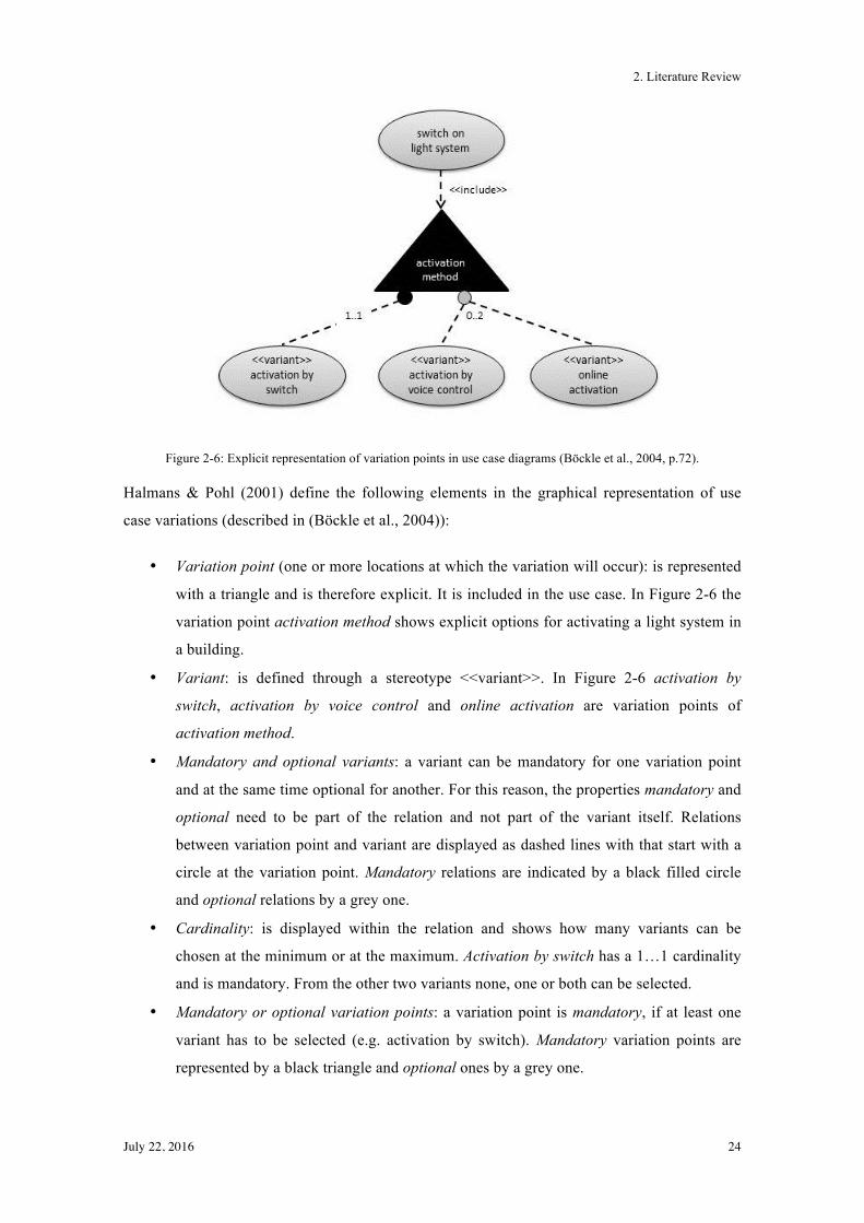
Figure 2-6: Explicit representation of variation points in use case diagrams (Böckle et al., 2004, p.72).
Halmans & Pohl (2001) define the following elements in the graphical representation of use
case variations (described in (Böckle et al., 2004)):
• Variation point (one or more locations at which the variation will occur): is represented
with a triangle and is therefore explicit. It is included in the use case. In Figure 2-6 the
variation point activation method shows explicit options for activating a light system in
a building.
• Variant: is defined through a stereotype <<variant>>. In Figure 2-6 activation by
switch, activation by voice control and online activation are variation points of
activation method.
• Mandatory and optional variants: a variant can be mandatory for one variation point
and at the same time optional for another. For this reason, the properties mandatory and
optional need to be part of the relation and not part of the variant itself. Relations
between variation point and variant are displayed as dashed lines with that start with a
circle at the variation point. Mandatory relations are indicated by a black filled circle
and optional relations by a grey one.
• Cardinality: is displayed within the relation and shows how many variants can be
chosen at the minimum or at the maximum. Activation by switch has a 1…1 cardinality
and is mandatory. From the other two variants none, one or both can be selected.
• Mandatory or optional variation points: a variation point is mandatory, if at least one
variant has to be selected (e.g. activation by switch). Mandatory variation points are
represented by a black triangle and optional ones by a grey one.
2. Literature Review
July 22, 2016 25
This modelling approach can be used to visualise variants in general. The concept itself can be
used as a starting point with respect to an application in the area of software for public
administration. However, because the concept is not yet adapted to the specific requirements in
that area, there is still a gap between modelling variants discussed in literature and actually
required, specific modelling strategies for the case at hand.
2.5 Summary
In the first part of the current chapter, the area of variant management for public administration
was introduced because the study focuses on this area. In the second part, basic terms such as
variant, variant management or software product lines (SPL) were defined. The definition of a
variant was followed by a subchapter, which describes the drivers of variants and variability.
The third part deals with variant management in general, i.e. what the challenges and goals are
and why reusability and maintenance need to be considered as well. To handle the variability in
products, software product lines are defined, including feature trees/feature models to
graphically display the variants. Furthermore, configuration management is described, which
deals with mapping features to code assets in order to build customer-specific products. In the
last part, a short overview over requirements engineering and modelling of the requirements
with use cases in combination with UML is given.
In variant management there are different approaches to handling variants, such as, e.g. software
product lines with feature trees for modelling it. But so far there is no specific solution for
handling variants and their interdependencies in the area of software for public administration.
However, generic approaches to variant management can be used and combined to generate a
solution for the specific area of software in public administration and the corresponding
requirements. This also includes a graphical representation of the variants and their
dependencies based on the requirements. As discussed so far, the generic concepts need to be
adapted in order to fully cover the requirements of this specific area.
The different approaches to variant management generally originate in the area of product
handling. In public administrations, the main focus is on topics related to eGov (electronic
Government) with focus on the processes. With respect to software applications for public
administrations and the corresponding processes, so far no adequate combination of variant
management with already known, more generic modelling approaches exists. However, there is
a need to have a well-defined method to handle these quite special kind of variants in this area,
which are mainly caused by laws and regulations, as, e.g., a change of a federal law may trickle
down and have an influence on municipality level, too.
3. Research Method
July 22, 2016 26
3. Research Method
3.1 Introduction
In order to answer the research questions, chapter 3 describes the research design of this study
including philosophy, approach, strategy, choice, time horizon, techniques and procedures. The
chosen research strategy, Design Science Research, is explained in more detail.
3.2 Research Onion
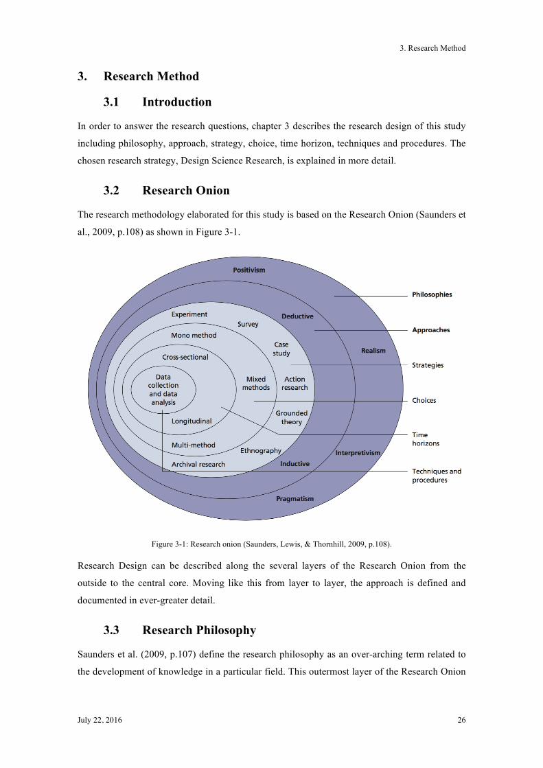
The research methodology elaborated for this study is based on the Research Onion (Saunders et
al., 2009, p.108) as shown in Figure 3-1.
Figure 3-1: Research onion (Saunders, Lewis, & Thornhill, 2009, p.108).
Research Design can be described along the several layers of the Research Onion from the
outside to the central core. Moving like this from layer to layer, the approach is defined and
documented in ever-greater detail.
3.3 Research Philosophy
Saunders et al. (2009, p.107) define the research philosophy as an over-arching term related to
the development of knowledge in a particular field. This outermost layer of the Research Onion
3. Research Method
July 22, 2016 27
includes positivism, realism, interpretivism and pragmatism as research philosophies (Saunders
et al., 2009, p.108). The authors describe positivism as working with general hypotheses that
can be tested, as is the case, e."g. in the natural sciences, where research can result in law-like
generalisations, and where the results can be replicated (Saunders et al., 2009, p.113). Realism
relates to scientific enquiries in which the researchers are independent and where several types
of research are used in order to obtain a more reliable outcome (Saunders et al., 2009, p.114).
Interpretivism refers to approaches underlining the necessity for the researcher to understand
differences between humans in our role as social actors (Saunders et al., 2009, p.115).
Interpretivism is the adopted research philosophy. It was chosen because of the fact that the
research has to be conducted in a subjective way (is influenced by personal opinions from the
interview partners and the researcher) and because it deals mainly with qualitative information.
3.4 Research Approach
Easterby-Smith et al. (2008) suggest three reasons why the choice of the research approach is
important (cited in (Saunders et al., 2009, p.126)):
• It enables to take a more informed decision about the research design.
• It helps to think about research strategies and choices.
• Knowledge of the different research traditions enables to adapt the research design in
order to comply with constraints.
Saunders et al. (2009, p.124) define two researches approaches; deduction as the testing theory
and induction as the building theory.
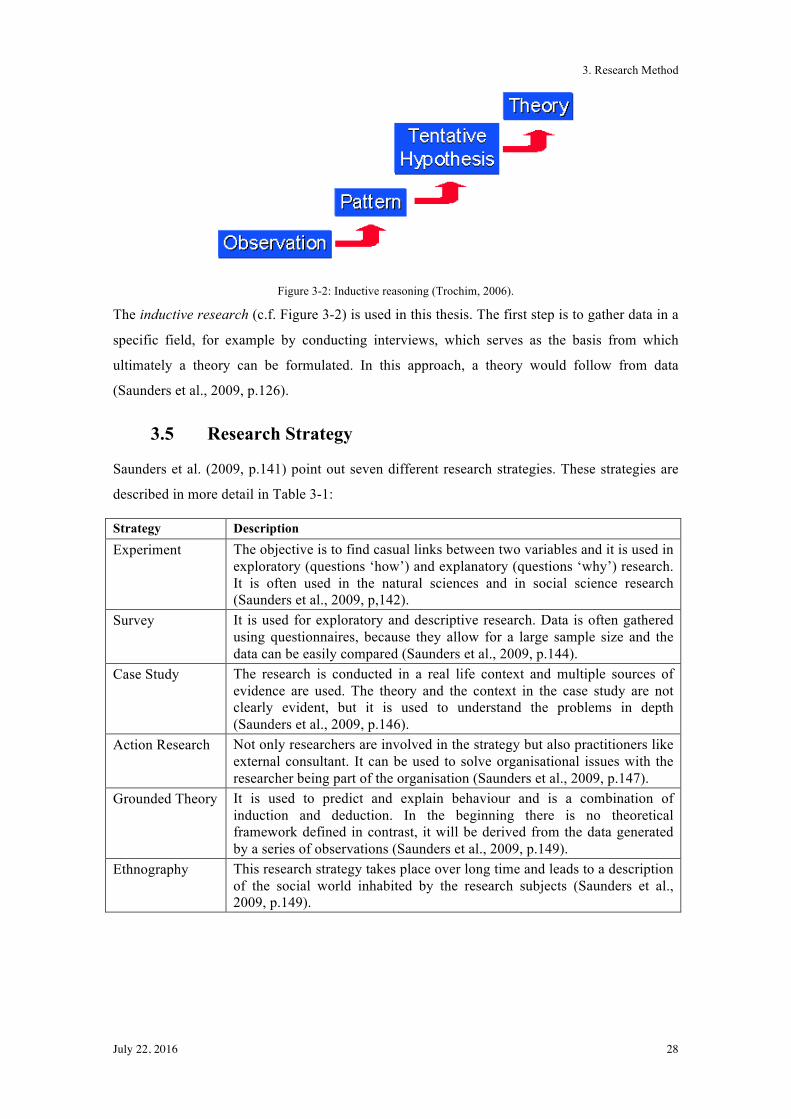
Trochim (2006) describes the deductive reasoning as a "top-down" approach, which starts with
the general theory and leads to the more specific hypotheses. Once a general theory has been
narrowed down to a more specific hypothesis it can be tested.
Inductive reasoning is described as a "bottom-up" approach. It starts with an observation, which
is used to establish o a broader generalisation and theories (Trochim, 2006).
3. Research Method
July 22, 2016 28
Figure 3-2: Inductive reasoning (Trochim, 2006).
The inductive research (c.f. Figure 3-2) is used in this thesis. The first step is to gather data in a
specific field, for example by conducting interviews, which serves as the basis from which
ultimately a theory can be formulated. In this approach, a theory would follow from data
(Saunders et al., 2009, p.126).
3.5 Research Strategy
Saunders et al. (2009, p.141) point out seven different research strategies. These strategies are
described in more detail in Table 3-1:
Strategy Description Experiment The objective is to find casual links between two variables and it is used in
exploratory (questions ‘how’) and explanatory (questions ‘why’) research. It is often used in the natural sciences and in social science research (Saunders et al., 2009, p,142).
Survey It is used for exploratory and descriptive research. Data is often gathered using questionnaires, because they allow for a large sample size and the data can be easily compared (Saunders et al., 2009, p.144).
Case Study The research is conducted in a real life context and multiple sources of evidence are used. The theory and the context in the case study are not clearly evident, but it is used to understand the problems in depth (Saunders et al., 2009, p.146).
Action Research Not only researchers are involved in the strategy but also practitioners like external consultant. It can be used to solve organisational issues with the researcher being part of the organisation (Saunders et al., 2009, p.147).
Grounded Theory It is used to predict and explain behaviour and is a combination of induction and deduction. In the beginning there is no theoretical framework defined in contrast, it will be derived from the data generated by a series of observations (Saunders et al., 2009, p.149).
Ethnography This research strategy takes place over long time and leads to a description of the social world inhabited by the research subjects (Saunders et al., 2009, p.149).
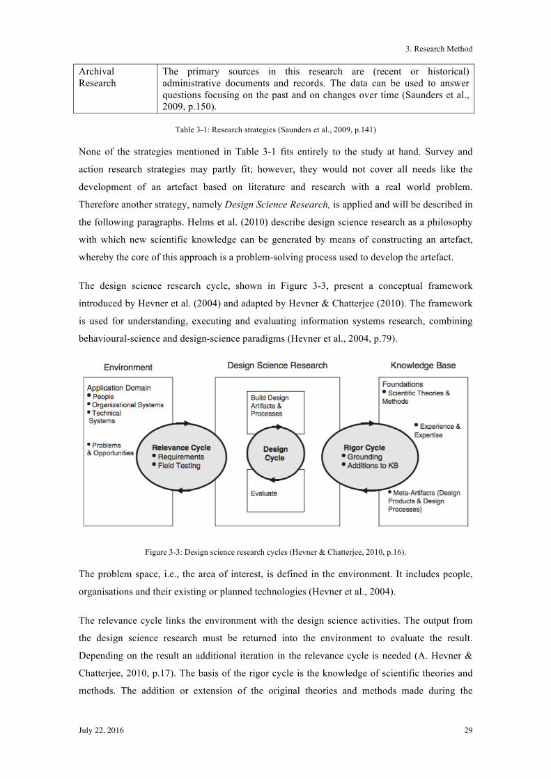
3. Research Method
July 22, 2016 29
Archival Research
The primary sources in this research are (recent or historical) administrative documents and records. The data can be used to answer questions focusing on the past and on changes over time (Saunders et al., 2009, p.150).
Table 3-1: Research strategies (Saunders et al., 2009, p.141)
None of the strategies mentioned in Table 3-1 fits entirely to the study at hand. Survey and
action research strategies may partly fit; however, they would not cover all needs like the
development of an artefact based on literature and research with a real world problem.
Therefore another strategy, namely Design Science Research, is applied and will be described in
the following paragraphs. Helms et al. (2010) describe design science research as a philosophy
with which new scientific knowledge can be generated by means of constructing an artefact,
whereby the core of this approach is a problem-solving process used to develop the artefact.
The design science research cycle, shown in Figure 3-3, present a conceptual framework
introduced by Hevner et al. (2004) and adapted by Hevner & Chatterjee (2010). The framework
is used for understanding, executing and evaluating information systems research, combining
behavioural-science and design-science paradigms (Hevner et al., 2004, p.79).
Figure 3-3: Design science research cycles (Hevner & Chatterjee, 2010, p.16).
The problem space, i.e., the area of interest, is defined in the environment. It includes people,
organisations and their existing or planned technologies (Hevner et al., 2004).
The relevance cycle links the environment with the design science activities. The output from
the design science research must be returned into the environment to evaluate the result.
Depending on the result an additional iteration in the relevance cycle is needed (A. Hevner &
Chatterjee, 2010, p.17). The basis of the rigor cycle is the knowledge of scientific theories and
methods. The addition or extension of the original theories and methods made during the
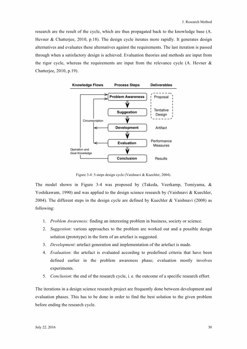
3. Research Method
July 22, 2016 30
research are the result of the cycle, which are thus propagated back to the knowledge base (A.
Hevner & Chatterjee, 2010, p.18). The design cycle iterates more rapidly. It generates design
alternatives and evaluates these alternatives against the requirements. The last iteration is passed
through when a satisfactory design is achieved. Evaluation theories and methods are input from
the rigor cycle, whereas the requirements are input from the relevance cycle (A. Hevner &
Chatterjee, 2010, p.19).
Figure 3-4: 5-steps design cycle (Vaishnavi & Kuechler, 2004).
The model shown in Figure 3-4 was proposed by (Takeda, Veerkamp, Tomiyama, &
Yoshikawam, 1990) and was applied to the design science research by (Vaishnavi & Kuechler,
2004). The different steps in the design cycle are defined by Kuechler & Vaishnavi (2008) as
following:
1. Problem Awareness: finding an interesting problem in business, society or science.
2. Suggestion: various approaches to the problem are worked out and a possible design
solution (prototype) in the form of an artefact is suggested.
3. Development: artefact generation and implementation of the artefact is made.
4. Evaluation: the artefact is evaluated according to predefined criteria that have been
defined earlier in the problem awareness phase; evaluation mostly involves
experiments.
5. Conclusion: the end of the research cycle, i."e. the outcome of a specific research effort.
The iterations in a design science research project are frequently done between development and
evaluation phases. This has to be done in order to find the best solution to the given problem
before ending the research cycle.
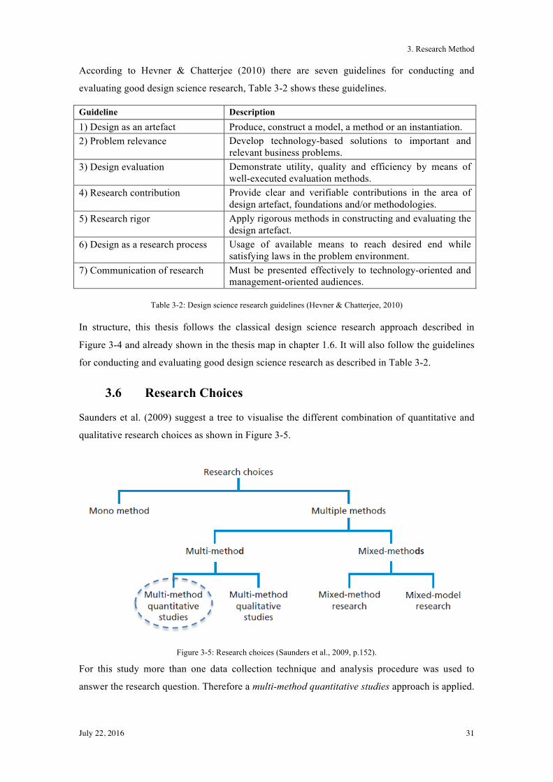
3. Research Method
July 22, 2016 31
According to Hevner & Chatterjee (2010) there are seven guidelines for conducting and
evaluating good design science research, Table 3-2 shows these guidelines.
Guideline Description 1) Design as an artefact Produce, construct a model, a method or an instantiation. 2) Problem relevance Develop technology-based solutions to important and
relevant business problems. 3) Design evaluation Demonstrate utility, quality and efficiency by means of
well-executed evaluation methods. 4) Research contribution Provide clear and verifiable contributions in the area of
design artefact, foundations and/or methodologies. 5) Research rigor Apply rigorous methods in constructing and evaluating the
design artefact. 6) Design as a research process Usage of available means to reach desired end while
satisfying laws in the problem environment. 7) Communication of research Must be presented effectively to technology-oriented and
management-oriented audiences.
Table 3-2: Design science research guidelines (Hevner & Chatterjee, 2010)
In structure, this thesis follows the classical design science research approach described in
Figure 3-4 and already shown in the thesis map in chapter 1.6. It will also follow the guidelines
for conducting and evaluating good design science research as described in Table 3-2.
3.6 Research Choices
Saunders et al. (2009) suggest a tree to visualise the different combination of quantitative and
qualitative research choices as shown in Figure 3-5.
Figure 3-5: Research choices (Saunders et al., 2009, p.152).
For this study more than one data collection technique and analysis procedure was used to
answer the research question. Therefore a multi-method quantitative studies approach is applied.
3. Research Method
July 22, 2016 32
It was a quantitative study because a data collection procedure with non-numerical data is
adopted (Saunders et al., 2009, p.151).
3.7 Time Horizons
With respect to time horizons Saunders et al. (2009, p.155) define two different types of studies:
• Cross-sectional studies: can be seen as a "snapshot" taken at a particular time. The
study of a particular phenomenon at a particular time.
• Longitudinal studies: can be seen as a diary or a series of snapshots and it has the
capacity that it has to study change and development.
For this study the cross-sectional studies approach was used to compare the different state-of-
the-art approaches in variant management and determine an adequate approach for variant
management in public administration.
3.8 Data Collection and Data Analysis
In order to understand what primary and secondary data means, the terms are explained
according to the definition given by Saunders et al. (2009, p.256):
• Primary data: data is collected especially for the purpose of a study, and hence the data
collection has to be carried out by the researcher himself
• Secondary data: is data that can be used in a given study, but that has originally been
collected for some other purpose. Such secondary data can comprise raw data sets as
well as published summaries.
Saunders et al. (2009) provide a visualisation of secondary data, shown in Figure 3-6, which
starts with the sub-groups of secondary data: documentary data, survey-based data and those
compiled from multiple sources.
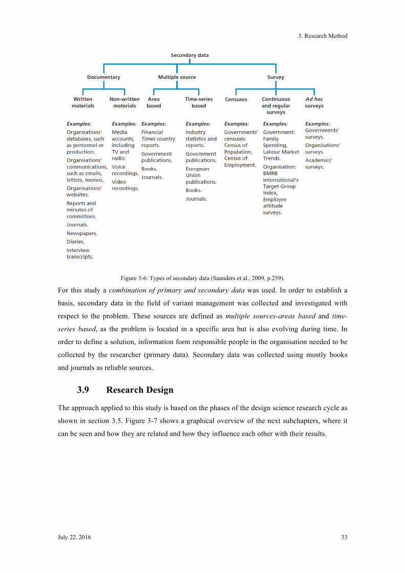
3. Research Method
July 22, 2016 33
Figure 3-6: Types of secondary data (Saunders et al., 2009, p.259).
For this study a combination of primary and secondary data was used. In order to establish a
basis, secondary data in the field of variant management was collected and investigated with
respect to the problem. These sources are defined as multiple sources-areas based and time-
series based, as the problem is located in a specific area but is also evolving during time. In
order to define a solution, information form responsible people in the organisation needed to be
collected by the researcher (primary data). Secondary data was collected using mostly books
and journals as reliable sources.
3.9 Research Design
The approach applied to this study is based on the phases of the design science research cycle as
shown in section 3.5. Figure 3-7 shows a graphical overview of the next subchapters, where it
can be seen and how they are related and how they influence each other with their results.
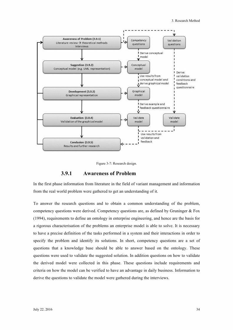
3. Research Method
July 22, 2016 34
Figure 3-7: Research design.
3.9.1 Awareness of Problem
In the first phase information from literature in the field of variant management and information
from the real world problem were gathered to get an understanding of it.
To answer the research questions and to obtain a common understanding of the problem,
competency questions were derived. Competency questions are, as defined by Gruninger & Fox
(1994), requirements to define an ontology in enterprise engineering, and hence are the basis for
a rigorous characterisation of the problems an enterprise model is able to solve. It is necessary
to have a precise definition of the tasks performed in a system and their interactions in order to
specify the problem and identify its solutions. In short, competency questions are a set of
questions that a knowledge base should be able to answer based on the ontology. These
questions were used to validate the suggested solution. In addition questions on how to validate
the derived model were collected in this phase. These questions include requirements and
criteria on how the model can be verified to have an advantage in daily business. Information to
derive the questions to validate the model were gathered during the interviews.
3. Research Method
July 22, 2016 35
The following techniques were used for this study in order to be aware of the problem and to
collect needed information:
The literature review builds up basic knowledge about the topic of variant management and was
thus used to get an overview of the used methods in handling variants today. It was used in the
awareness phase mainly to answer the research question 2 and 3.
Interviews were used to obtain a basic understanding of the problem and the area the
interviewee was working in. In the first phase of the interviews, they were semi-structured and
informal. The main goal was to explore the area of the research in greater depth (Saunders et al.,
2009, p.321). As there are different needs and views on software and the variants associated
with it, information was gathered from different people in the enterprise; the product managers
and the software engineers. In this thesis three major products in the area of public
administration software applications were used to gather information. These products are
located in the area of land charge registers (internal name: Capitastra), resident register (internal
name: RREG, is located in Geres environment) and software for social work (internal name:
KiSS). From every product, the respective product manager and a software engineer provided
information in the interviews. The results of the interviews were used to derive an ontology for
competency question in the area of variant management for software applications in public
administrations. The goal was to identify all relevant questions which have to be answered by a
product manager and a software engineer in order to handle new variants and the requirements
of them.
Focus groups are defined as non-standard interviews with a clearly and precisely defined topic
that are carried out on a group basis (Saunders et al., 2009, p.343). If the interviews did not fully
cover the needed information or the interview partners or researcher have problem
communication at the same level a group discussion for a certain topic, a focus group would be
formed. In the focus group, if formed, the product managers and software engineers, which also
participated in the interviews, sould be part of it. If it shows during the process, that there are
too many people in the focus group or the opinions in the topic differ too much, the focus group
would be split up into two groups. The product managers would then form one focus group and
the software engineers would form the other one.
3.9.2 Suggestion
In the suggestion phase, a conceptual model of how to handle the variants and the requirements
was derived. To do so, a graphical model, for example in a UML (Unified Modelling Language)
representation, was created based on literature review and the results from the interviews.
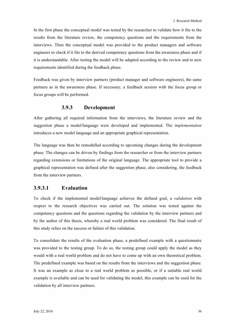
3. Research Method
July 22, 2016 36
In the first phase the conceptual model was tested by the researcher to validate how it fits to the
results from the literature review, the competency questions and the requirements from the
interviews. Then the conceptual model was provided to the product managers and software
engineers to check if it fits to the derived competency questions from the awareness phase and if
it is understandable. After testing the model will be adapted according to the review and to new
requirements identified during the feedback phase.
Feedback was given by interview partners (product manager and software engineers), the same
partners as in the awareness phase. If necessary, a feedback session with the focus group or
focus groups will be performed.
3.9.3 Development
After gathering all required information from the interviews, the literature review and the
suggestion phase a model/language were developed and implemented. The implementation
introduces a new model language and an appropriate graphical representation.
The language was then be remodelled according to upcoming changes during the development
phase. The changes can be driven by findings from the researcher or from the interview partners
regarding extensions or limitations of the original language. The appropriate tool to provide a
graphical representation was defined after the suggestion phase, also considering, the feedback
from the interview partners.
3.9.3.1 Evaluation
To check if the implemented model/language achieves the defined goal, a validation with
respect to the research objectives was carried out. The solution was tested against the
competency questions and the questions regarding the validation by the interview partners and
by the author of this thesis, whereby a real world problem was considered. The final result of
this study relies on the success or failure of this validation.
To consolidate the results of the evaluation phase, a predefined example with a questionnaire
was provided to the testing group. To do so, the testing group could apply the model as they
would with a real world problem and do not have to come up with an own theoretical problem.
The predefined example was based on the results from the interviews and the suggestion phase.
It was an example as close to a real world problem as possible, or if a suitable real world
example is available and can be used for validating the model, this example can be used for the
validation by all interview partners.
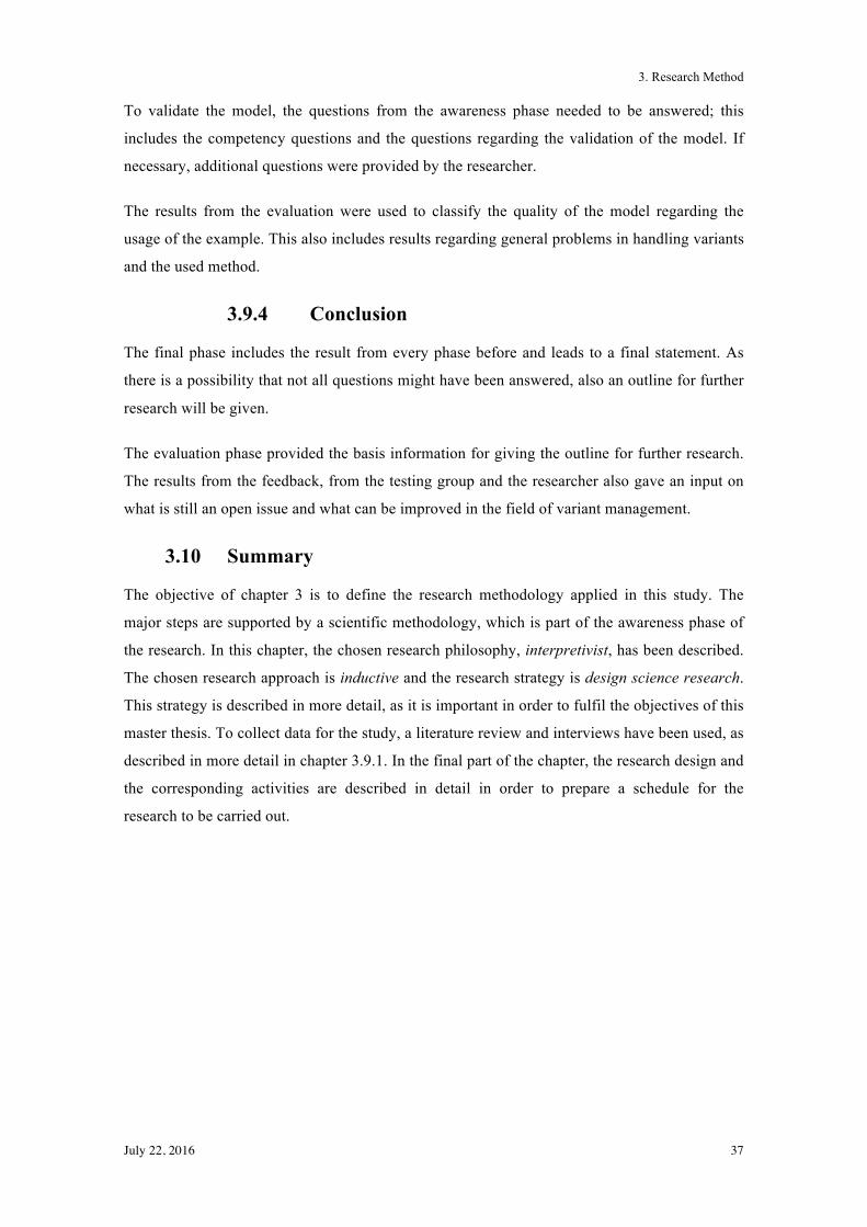
3. Research Method
July 22, 2016 37
To validate the model, the questions from the awareness phase needed to be answered; this
includes the competency questions and the questions regarding the validation of the model. If
necessary, additional questions were provided by the researcher.
The results from the evaluation were used to classify the quality of the model regarding the
usage of the example. This also includes results regarding general problems in handling variants
and the used method.
3.9.4 Conclusion
The final phase includes the result from every phase before and leads to a final statement. As
there is a possibility that not all questions might have been answered, also an outline for further
research will be given.
The evaluation phase provided the basis information for giving the outline for further research.
The results from the feedback, from the testing group and the researcher also gave an input on
what is still an open issue and what can be improved in the field of variant management.
3.10 Summary
The objective of chapter 3 is to define the research methodology applied in this study. The
major steps are supported by a scientific methodology, which is part of the awareness phase of
the research. In this chapter, the chosen research philosophy, interpretivist, has been described.
The chosen research approach is inductive and the research strategy is design science research.
This strategy is described in more detail, as it is important in order to fulfil the objectives of this
master thesis. To collect data for the study, a literature review and interviews have been used, as
described in more detail in chapter 3.9.1. In the final part of the chapter, the research design and
the corresponding activities are described in detail in order to prepare a schedule for the
research to be carried out.
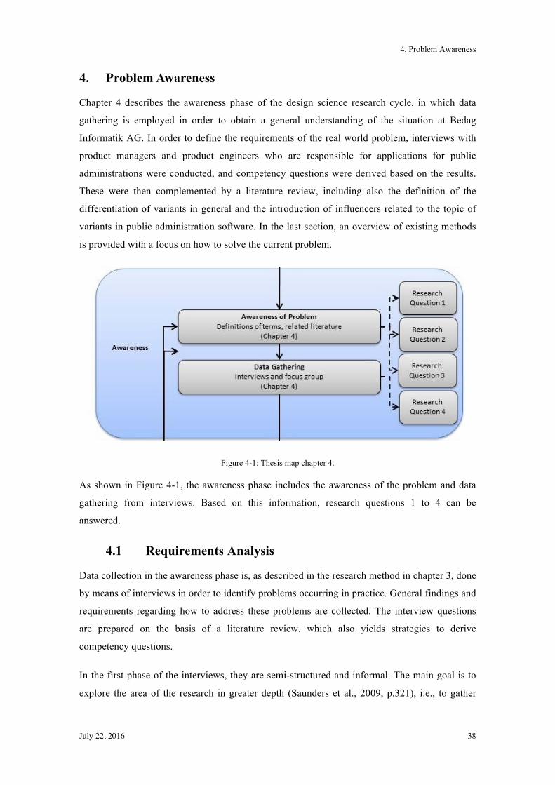
4. Problem Awareness
July 22, 2016 38
4. Problem Awareness
Chapter 4 describes the awareness phase of the design science research cycle, in which data
gathering is employed in order to obtain a general understanding of the situation at Bedag
Informatik AG. In order to define the requirements of the real world problem, interviews with
product managers and product engineers who are responsible for applications for public
administrations were conducted, and competency questions were derived based on the results.
These were then complemented by a literature review, including also the definition of the
differentiation of variants in general and the introduction of influencers related to the topic of
variants in public administration software. In the last section, an overview of existing methods
is provided with a focus on how to solve the current problem.
Figure 4-1: Thesis map chapter 4.
As shown in Figure 4-1, the awareness phase includes the awareness of the problem and data
gathering from interviews. Based on this information, research questions 1 to 4 can be
answered.
4.1 Requirements Analysis
Data collection in the awareness phase is, as described in the research method in chapter 3, done
by means of interviews in order to identify problems occurring in practice. General findings and
requirements regarding how to address these problems are collected. The interview questions
are prepared on the basis of a literature review, which also yields strategies to derive
competency questions.
In the first phase of the interviews, they are semi-structured and informal. The main goal is to
explore the area of the research in greater depth (Saunders et al., 2009, p.321), i.e., to gather
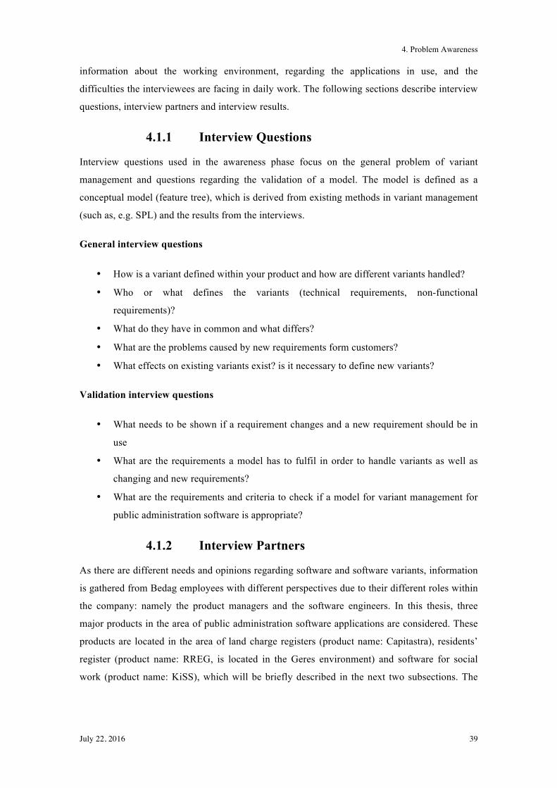
4. Problem Awareness
July 22, 2016 39
information about the working environment, regarding the applications in use, and the
difficulties the interviewees are facing in daily work. The following sections describe interview
questions, interview partners and interview results.
4.1.1 Interview Questions
Interview questions used in the awareness phase focus on the general problem of variant
management and questions regarding the validation of a model. The model is defined as a
conceptual model (feature tree), which is derived from existing methods in variant management
(such as, e.g. SPL) and the results from the interviews.
General interview questions
• How is a variant defined within your product and how are different variants handled?
• Who or what defines the variants (technical requirements, non-functional
requirements)?
• What do they have in common and what differs?
• What are the problems caused by new requirements form customers?
• What effects on existing variants exist? is it necessary to define new variants?
Validation interview questions
• What needs to be shown if a requirement changes and a new requirement should be in
use
• What are the requirements a model has to fulfil in order to handle variants as well as
changing and new requirements?
• What are the requirements and criteria to check if a model for variant management for
public administration software is appropriate?
4.1.2 Interview Partners
As there are different needs and opinions regarding software and software variants, information
is gathered from Bedag employees with different perspectives due to their different roles within
the company: namely the product managers and the software engineers. In this thesis, three
major products in the area of public administration software applications are considered. These
products are located in the area of land charge registers (product name: Capitastra), residents’
register (product name: RREG, is located in the Geres environment) and software for social
work (product name: KiSS), which will be briefly described in the next two subsections. The
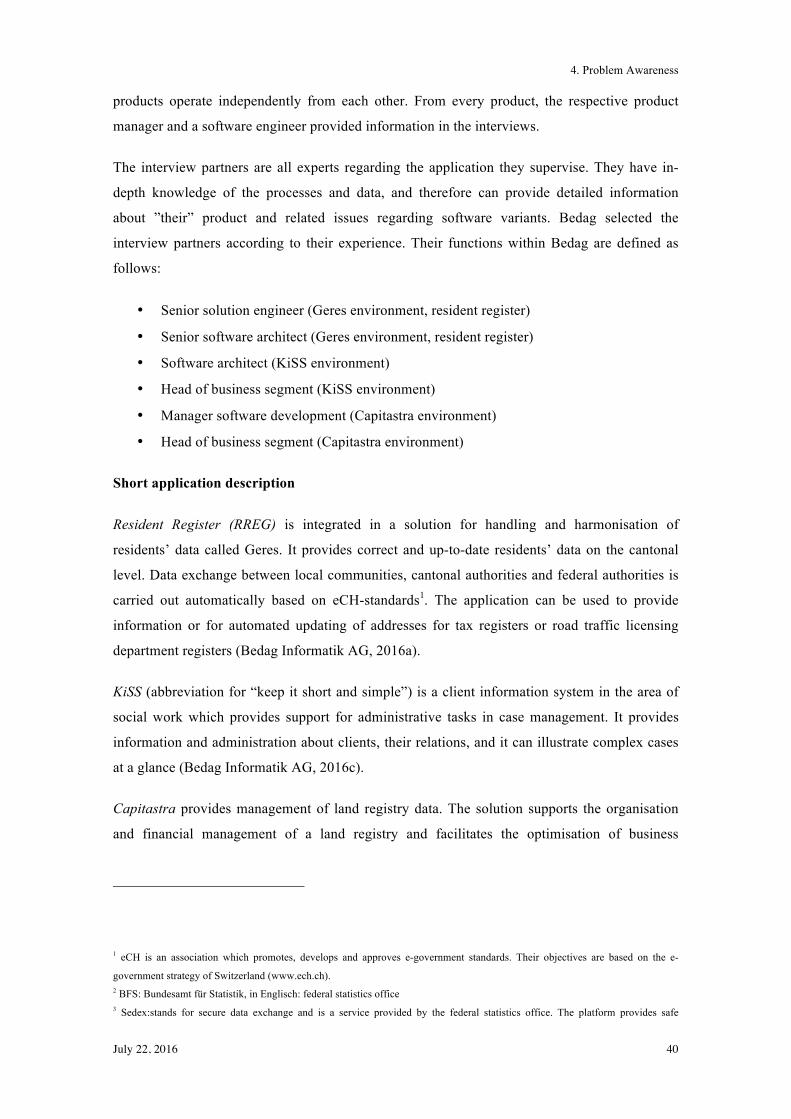
4. Problem Awareness
July 22, 2016 40
products operate independently from each other. From every product, the respective product
manager and a software engineer provided information in the interviews.
The interview partners are all experts regarding the application they supervise. They have in-
depth knowledge of the processes and data, and therefore can provide detailed information
about ”their” product and related issues regarding software variants. Bedag selected the
interview partners according to their experience. Their functions within Bedag are defined as
follows:
• Senior solution engineer (Geres environment, resident register)
• Senior software architect (Geres environment, resident register)
• Software architect (KiSS environment)
• Head of business segment (KiSS environment)
• Manager software development (Capitastra environment)
• Head of business segment (Capitastra environment)
Short application description
Resident Register (RREG) is integrated in a solution for handling and harmonisation of
residents’ data called Geres. It provides correct and up-to-date residents’ data on the cantonal
level. Data exchange between local communities, cantonal authorities and federal authorities is
carried out automatically based on eCH-standards1. The application can be used to provide
information or for automated updating of addresses for tax registers or road traffic licensing
department registers (Bedag Informatik AG, 2016a).
KiSS (abbreviation for “keep it short and simple”) is a client information system in the area of
social work which provides support for administrative tasks in case management. It provides
information and administration about clients, their relations, and it can illustrate complex cases
at a glance (Bedag Informatik AG, 2016c).
Capitastra provides management of land registry data. The solution supports the organisation
and financial management of a land registry and facilitates the optimisation of business
1 eCH is an association which promotes, develops and approves e-government standards. Their objectives are based on the e-
government strategy of Switzerland (www.ech.ch). 2 BFS: Bundesamt für Statistik, in Englisch: federal statistics office 3 Sedex:stands for secure data exchange and is a service provided by the federal statistics office. The platform provides safe
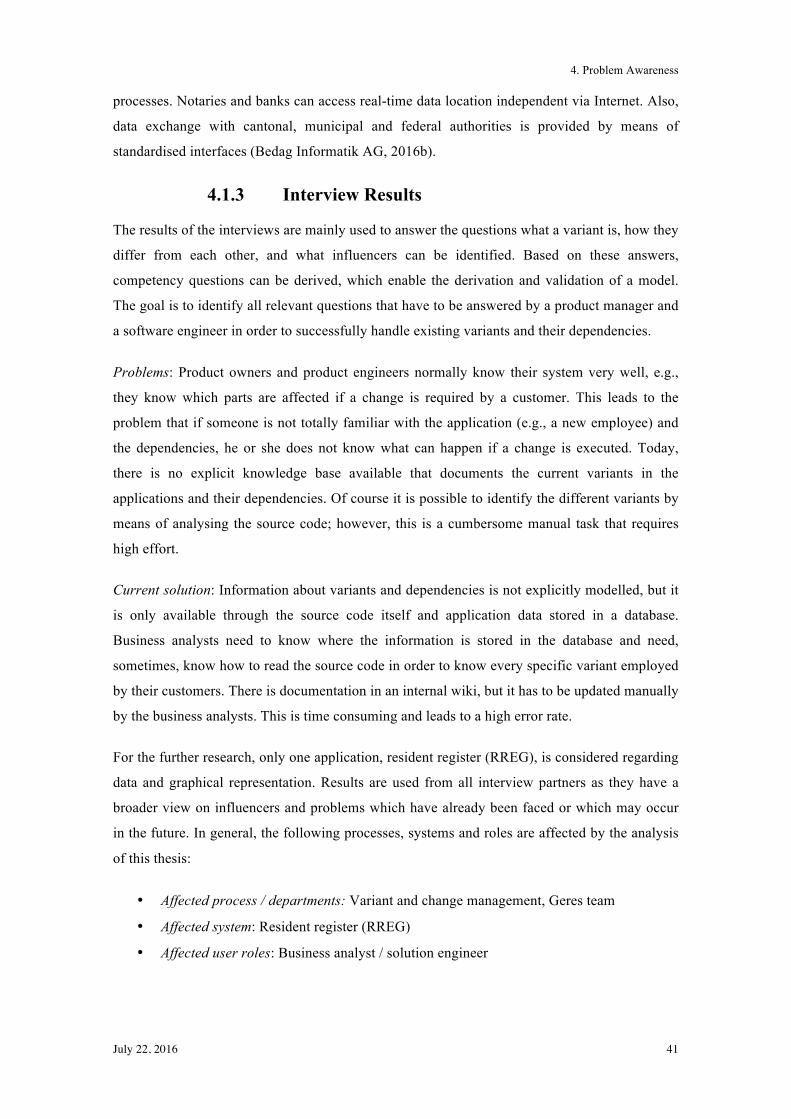
4. Problem Awareness
July 22, 2016 41
processes. Notaries and banks can access real-time data location independent via Internet. Also,
data exchange with cantonal, municipal and federal authorities is provided by means of
standardised interfaces (Bedag Informatik AG, 2016b).
4.1.3 Interview Results
The results of the interviews are mainly used to answer the questions what a variant is, how they
differ from each other, and what influencers can be identified. Based on these answers,
competency questions can be derived, which enable the derivation and validation of a model.
The goal is to identify all relevant questions that have to be answered by a product manager and
a software engineer in order to successfully handle existing variants and their dependencies.
Problems: Product owners and product engineers normally know their system very well, e.g.,
they know which parts are affected if a change is required by a customer. This leads to the
problem that if someone is not totally familiar with the application (e.g., a new employee) and
the dependencies, he or she does not know what can happen if a change is executed. Today,
there is no explicit knowledge base available that documents the current variants in the
applications and their dependencies. Of course it is possible to identify the different variants by
means of analysing the source code; however, this is a cumbersome manual task that requires
high effort.
Current solution: Information about variants and dependencies is not explicitly modelled, but it
is only available through the source code itself and application data stored in a database.
Business analysts need to know where the information is stored in the database and need,
sometimes, know how to read the source code in order to know every specific variant employed
by their customers. There is documentation in an internal wiki, but it has to be updated manually
by the business analysts. This is time consuming and leads to a high error rate.
For the further research, only one application, resident register (RREG), is considered regarding
data and graphical representation. Results are used from all interview partners as they have a
broader view on influencers and problems which have already been faced or which may occur
in the future. In general, the following processes, systems and roles are affected by the analysis
of this thesis:
• Affected process / departments: Variant and change management, Geres team
• Affected system: Resident register (RREG)
• Affected user roles: Business analyst / solution engineer
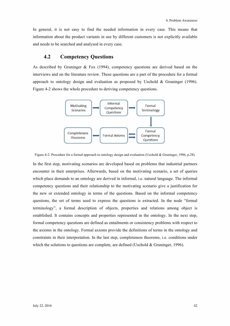
4. Problem Awareness
July 22, 2016 42
In general, it is not easy to find the needed information in every case. This means that
information about the product variants in use by different customers is not explicitly available
and needs to be searched and analysed in every case.
4.2 Competency Questions
As described by Gruninger & Fox (1994), competency questions are derived based on the
interviews and on the literature review. These questions are a part of the procedure for a formal
approach to ontology design and evaluation as proposed by Uschold & Gruninger (1996).
Figure 4-2 shows the whole procedure to deriving competency questions.
Figure 4-2: Procedure for a formal approach to ontology design and evaluation (Uschold & Gruninger, 1996, p.28).
In the first step, motivating scenarios are developed based on problems that industrial partners
encounter in their enterprises. Afterwards, based on the motivating scenario, a set of queries
which place demands to an ontology are derived in informal, i.e. natural language. The informal
competency questions and their relationship to the motivating scenario give a justification for
the new or extended ontology in terms of the questions. Based on the informal competency
questions, the set of terms used to express the questions is extracted. In the node “formal
terminology”, a formal description of objects, properties and relations among object is
established. It contains concepts and properties represented in the ontology. In the next step,
formal competency questions are defined as entailments or consistency problems with respect to
the axioms in the ontology. Formal axioms provide the definitions of terms in the ontology and
constraints in their interpretation. In the last step, completeness theorems, i.e. conditions under
which the solutions to questions are complete, are defined (Uschold & Gruninger, 1996).
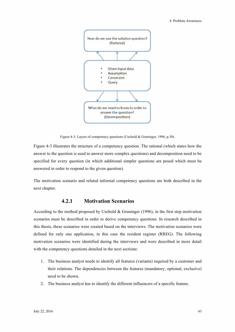
4. Problem Awareness
July 22, 2016 43
Figure 4-3: Layers of competency questions (Uschold & Gruninger, 1996, p.30).
Figure 4-3 illustrates the structure of a competency question. The rational (which states how the
answer to the question is used to answer more complex questions) and decomposition need to be
specified for every question (in which additional simpler questions are posed which must be
answered in order to respond to the given question).
The motivation scenario and related informal competency questions are both described in the
next chapter.
4.2.1 Motivation Scenarios
According to the method proposed by Uschold & Gruninger (1996), in the first step motivation
scenarios must be described in order to derive competency questions. In research described in
this thesis, these scenarios were created based on the interviews. The motivation scenarios were
defined for only one application, in this case the resident register (RREG). The following
motivation scenarios were identified during the interviews and were described in more detail
with the competency questions detailed in the next sections:
1. The business analyst needs to identify all features (variants) required by a customer and
their relations. The dependencies between the features (mandatory, optional, exclusive)
need to be shown.
2. The business analyst has to identify the different influencers of a specific feature.
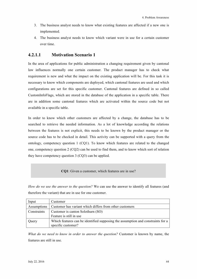
4. Problem Awareness
July 22, 2016 44
3. The business analyst needs to know what existing features are affected if a new one is
implemented.
4. The business analyst needs to know which variant were in use for a certain customer
over time.
4.2.1.1 Motivation Scenario 1
In the area of applications for public administration a changing requirement given by cantonal
law influences normally one certain customer. The product manager has to check what
requirement is new and what the impact on the existing application will be. For this task it is
necessary to know which components are deployed, which cantonal features are used and which
configurations are set for this specific customer. Cantonal features are defined in so called
CustomInfoFlags, which are stored in the database of the application in a specific table. There
are in addition some cantonal features which are activated within the source code but not
available in a specific table.
In order to know which other customers are affected by a change, the database has to be
searched to retrieve the needed information. As a lot of knowledge according the relations
between the features is not explicit, this needs to be known by the product manager or the
source code has to be checked in detail. This activity can be supported with a query from the
ontology, competency question 1 (CQ1). To know which features are related to the changed
one, competency question 2 (CQ2) can be used to find them, and to know which sort of relation
they have competency question 3 (CQ3) can be applied.
How do we use the answer to the question? We can use the answer to identify all features (and
therefore the variant) that are in use for one customer.
Input Customer Assumptions Customer has variant which differs from other customers Constraints Customer is canton Solothurn (SO)
Feature is still in use Query Which features can be identified supposing the assumption and constraints for a
specific customer?
What do we need to know in order to answer the question? Customer is known by name, the
features are still in use.
CQ1: Given a customer, which features are in use?
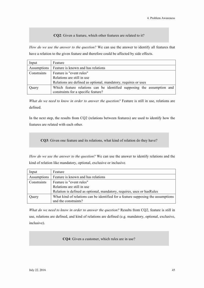
4. Problem Awareness
July 22, 2016 45
How do we use the answer to the question? We can use the answer to identify all features that
have a relation to the given feature and therefore could be affected by side effects.
Input Feature Assumptions Feature is known and has relations Constraints Feature is "event rules"
Relations are still in use Relations are defined as optional, mandatory, requires or uses
Query Which feature relations can be identified supposing the assumption and constraints for a specific feature?
What do we need to know in order to answer the question? Feature is still in use, relations are
defined.
In the next step, the results from CQ2 (relations between features) are used to identify how the
features are related with each other.
How do we use the answer to the question? We can use the answer to identify relations and the
kind of relation like mandatory, optional, exclusive or inclusive.
Input Feature Assumptions Feature is known and has relations Constraints Feature is "event rules"
Relations are still in use Relation is defined as optional, mandatory, requires, uses or hasRules
Query What kind of relations can be identified for a feature supposing the assumptions and the constraints?
What do we need to know in order to answer the question? Results from CQ2, feature is still in
use, relations are defined, and kind of relations are defined (e.g. mandatory, optional, exclusive,
inclusive).
CQ2: Given a feature, which other features are related to it?
CQ3: Given one feature and its relations, what kind of relation do they have?
CQ4: Given a customer, which rules are in use?
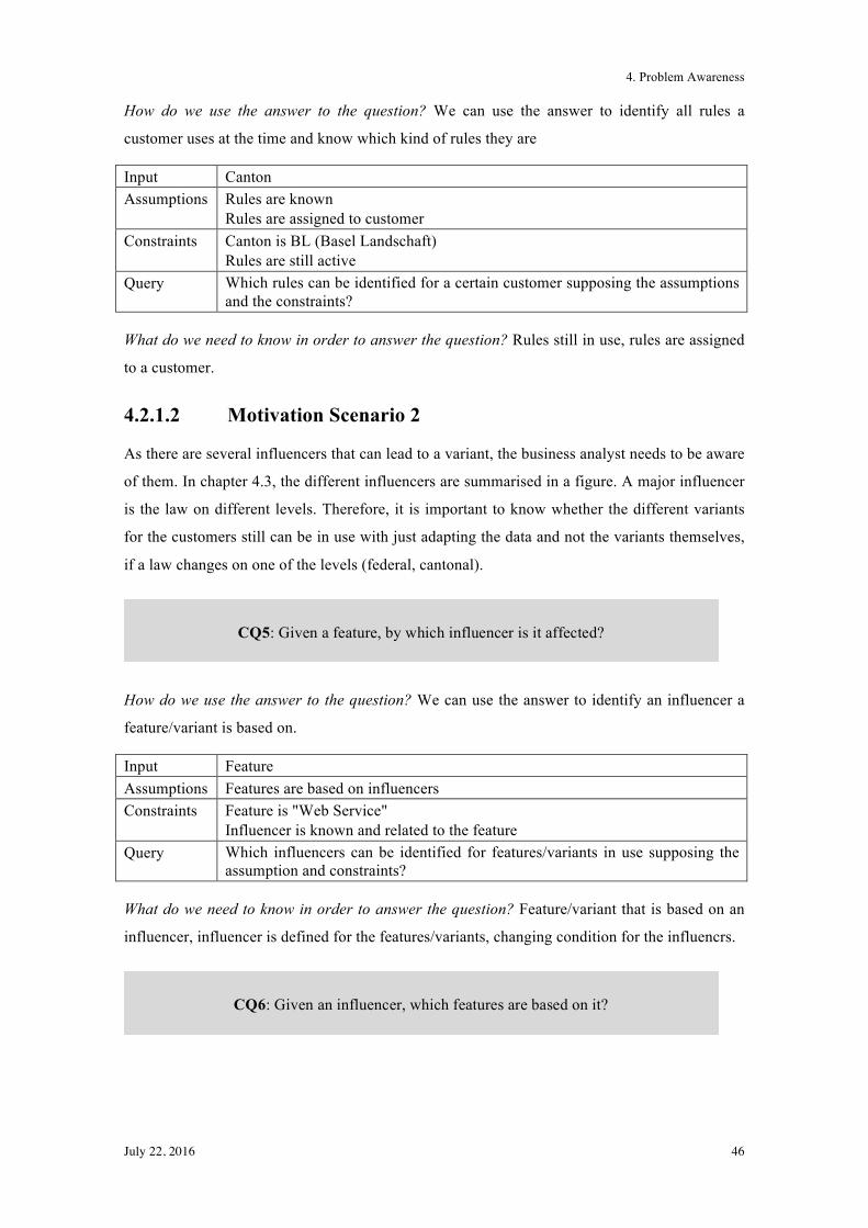
4. Problem Awareness
July 22, 2016 46
How do we use the answer to the question? We can use the answer to identify all rules a
customer uses at the time and know which kind of rules they are
Input Canton Assumptions Rules are known
Rules are assigned to customer Constraints Canton is BL (Basel Landschaft)
Rules are still active Query Which rules can be identified for a certain customer supposing the assumptions
and the constraints?
What do we need to know in order to answer the question? Rules still in use, rules are assigned
to a customer.
4.2.1.2 Motivation Scenario 2
As there are several influencers that can lead to a variant, the business analyst needs to be aware
of them. In chapter 4.3, the different influencers are summarised in a figure. A major influencer
is the law on different levels. Therefore, it is important to know whether the different variants
for the customers still can be in use with just adapting the data and not the variants themselves,
if a law changes on one of the levels (federal, cantonal).
How do we use the answer to the question? We can use the answer to identify an influencer a
feature/variant is based on.
Input Feature Assumptions Features are based on influencers Constraints Feature is "Web Service"
Influencer is known and related to the feature Query Which influencers can be identified for features/variants in use supposing the
assumption and constraints?
What do we need to know in order to answer the question? Feature/variant that is based on an
influencer, influencer is defined for the features/variants, changing condition for the influencrs.
CQ5: Given a feature, by which influencer is it affected?
CQ6: Given an influencer, which features are based on it?
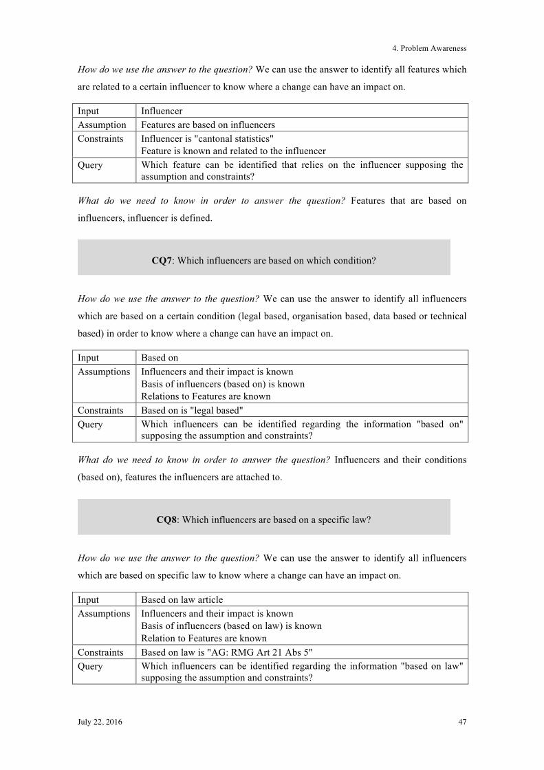
4. Problem Awareness
July 22, 2016 47
How do we use the answer to the question? We can use the answer to identify all features which
are related to a certain influencer to know where a change can have an impact on.
Input Influencer Assumption Features are based on influencers Constraints Influencer is "cantonal statistics"
Feature is known and related to the influencer Query Which feature can be identified that relies on the influencer supposing the
assumption and constraints?
What do we need to know in order to answer the question? Features that are based on
influencers, influencer is defined.
How do we use the answer to the question? We can use the answer to identify all influencers
which are based on a certain condition (legal based, organisation based, data based or technical
based) in order to know where a change can have an impact on.
Input Based on Assumptions Influencers and their impact is known
Basis of influencers (based on) is known Relations to Features are known
Constraints Based on is "legal based" Query Which influencers can be identified regarding the information "based on"
supposing the assumption and constraints?
What do we need to know in order to answer the question? Influencers and their conditions
(based on), features the influencers are attached to.
How do we use the answer to the question? We can use the answer to identify all influencers
which are based on specific law to know where a change can have an impact on.
Input Based on law article Assumptions Influencers and their impact is known
Basis of influencers (based on law) is known Relation to Features are known
Constraints Based on law is "AG: RMG Art 21 Abs 5" Query Which influencers can be identified regarding the information "based on law"
supposing the assumption and constraints?
CQ7: Which influencers are based on which condition?
CQ8: Which influencers are based on a specific law?
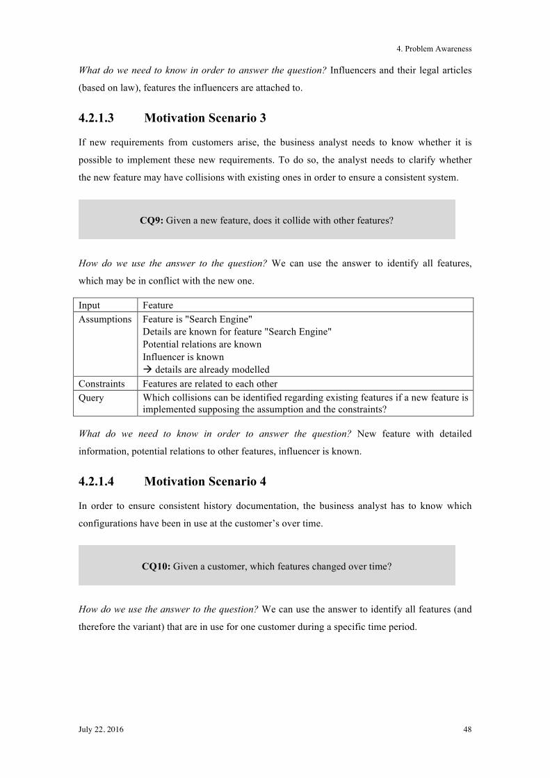
4. Problem Awareness
July 22, 2016 48
What do we need to know in order to answer the question? Influencers and their legal articles
(based on law), features the influencers are attached to.
4.2.1.3 Motivation Scenario 3
If new requirements from customers arise, the business analyst needs to know whether it is
possible to implement these new requirements. To do so, the analyst needs to clarify whether
the new feature may have collisions with existing ones in order to ensure a consistent system.
How do we use the answer to the question? We can use the answer to identify all features,
which may be in conflict with the new one.
Input Feature Assumptions Feature is "Search Engine"
Details are known for feature "Search Engine" Potential relations are known Influencer is known ! details are already modelled
Constraints Features are related to each other Query Which collisions can be identified regarding existing features if a new feature is
implemented supposing the assumption and the constraints?
What do we need to know in order to answer the question? New feature with detailed
information, potential relations to other features, influencer is known.
4.2.1.4 Motivation Scenario 4
In order to ensure consistent history documentation, the business analyst has to know which
configurations have been in use at the customer’s over time.
How do we use the answer to the question? We can use the answer to identify all features (and
therefore the variant) that are in use for one customer during a specific time period.
CQ9: Given a new feature, does it collide with other features?
CQ10: Given a customer, which features changed over time?
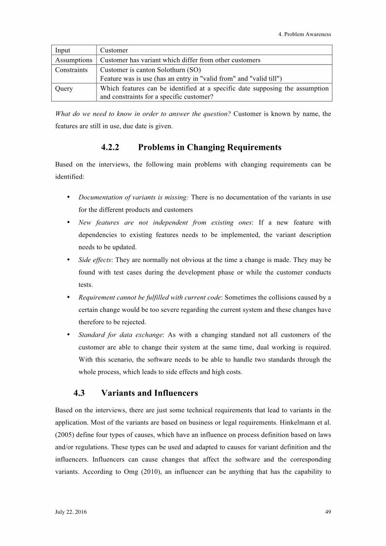
4. Problem Awareness
July 22, 2016 49
Input Customer Assumptions Customer has variant which differ from other customers Constraints Customer is canton Solothurn (SO)
Feature was is use (has an entry in "valid from" and "valid till") Query Which features can be identified at a specific date supposing the assumption
and constraints for a specific customer?
What do we need to know in order to answer the question? Customer is known by name, the
features are still in use, due date is given.
4.2.2 Problems in Changing Requirements
Based on the interviews, the following main problems with changing requirements can be
identified:
• Documentation of variants is missing: There is no documentation of the variants in use
for the different products and customers
• New features are not independent from existing ones: If a new feature with
dependencies to existing features needs to be implemented, the variant description
needs to be updated.
• Side effects: They are normally not obvious at the time a change is made. They may be
found with test cases during the development phase or while the customer conducts
tests.
• Requirement cannot be fulfilled with current code: Sometimes the collisions caused by a
certain change would be too severe regarding the current system and these changes have
therefore to be rejected.
• Standard for data exchange: As with a changing standard not all customers of the
customer are able to change their system at the same time, dual working is required.
With this scenario, the software needs to be able to handle two standards through the
whole process, which leads to side effects and high costs.
4.3 Variants and Influencers
Based on the interviews, there are just some technical requirements that lead to variants in the
application. Most of the variants are based on business or legal requirements. Hinkelmann et al.
(2005) define four types of causes, which have an influence on process definition based on laws
and/or regulations. These types can be used and adapted to causes for variant definition and the
influencers. Influencers can cause changes that affect the software and the corresponding
variants. According to Omg (2010), an influencer can be anything that has the capability to
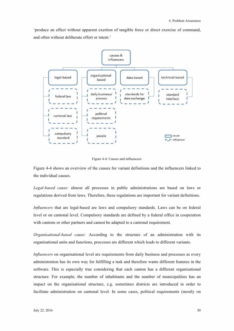
4. Problem Awareness
July 22, 2016 50
‘produce an effect without apparent exertion of tangible force or direct exercise of command,
and often without deliberate effort or intent.’
Figure 4-4: Causes and influencers.
Figure 4-4 shows an overview of the causes for variant definitions and the influencers linked to
the individual causes.
Legal-based cause: almost all processes in public administrations are based on laws or
regulations derived from laws. Therefore, these regulations are important for variant definitions.
Influencers that are legal-based are laws and compulsory standards. Laws can be on federal
level or on cantonal level. Compulsory standards are defined by a federal office in cooperation
with cantons or other partners and cannot be adapted to a cantonal requirement.
Organisational-based cause: According to the structure of an administration with its
organisational units and functions, processes are different which leads to different variants.
Influencers on organisational level are requirements from daily business and processes as every
administration has its own way for fulfilling a task and therefore wants different features in the
software. This is especially true considering that each canton has a different organisational
structure. For example, the number of inhabitants and the number of municipalities has an
impact on the organisational structure, e.g. sometimes districts are introduced in order to
facilitate administration on cantonal level. In some cases, political requirements (mostly on
4. Problem Awareness
July 22, 2016 51
cantonal level) can have an influence; it may have the same effect as requirements from daily
business, but from a different basis. Based on the area an application is located in, people can
also have an influence. If the area is more located in social work, the influence from a single
person on software is greater than in areas that are more located in general administration. This
is the case because in social work, the application is just a tool to provide and update the needed
information and not the main focus of daily work.
Data-based cause: Data required by a specific process can have an effect, because the data may
be generated during the execution of a process, which then leads to a certain order of activities.
Influencers on data level are standards for data exchange that do not have compulsory character
but are a basis to exchange data.
Technical cause: Not just organisational or legal requirements determine a design, but also
technical ones. Data can be checked at two different points in one process in order to guarantee
data security (e.g. web service to check person data and general process to check completeness).
Influencers on technical level are standard interfaces, which are used to communicate with other
federal or cantonal applications in order to exchange data.
4.3.1 Differences in Variants/Variability
The basis for developing software in the software product line approach are core assets, a
collection of artefacts, that have been designed especially for use across the portfolio
(Bachmann & Clements, 2005). According to Thiel & Hein (2002), all product line artefacts are
affected by variability. The variation point is often implicit and hard to identify. In literature,
variability is often used in the context of SPLs to show how software can be described in order
to handle different variants of the same core software. Therefore, variability will be described in
more detail in the following paragraphs.
“Software variability is the ability of a software system or artefact to be changed, customized or
configured for use in a particular context (Beuche, Papajewski, & Schröder-Preikschat, 2004)”.
Bachmann & Clements (2005) add in their definition of variability that it supports the
production of a set of artefacts that differ from each other in a pre-panned fashion.
According to Bachmann & Clements (2005), there are several ways to define a product. Table
4-1 shows the different variability concepts to support product-by-product variation.
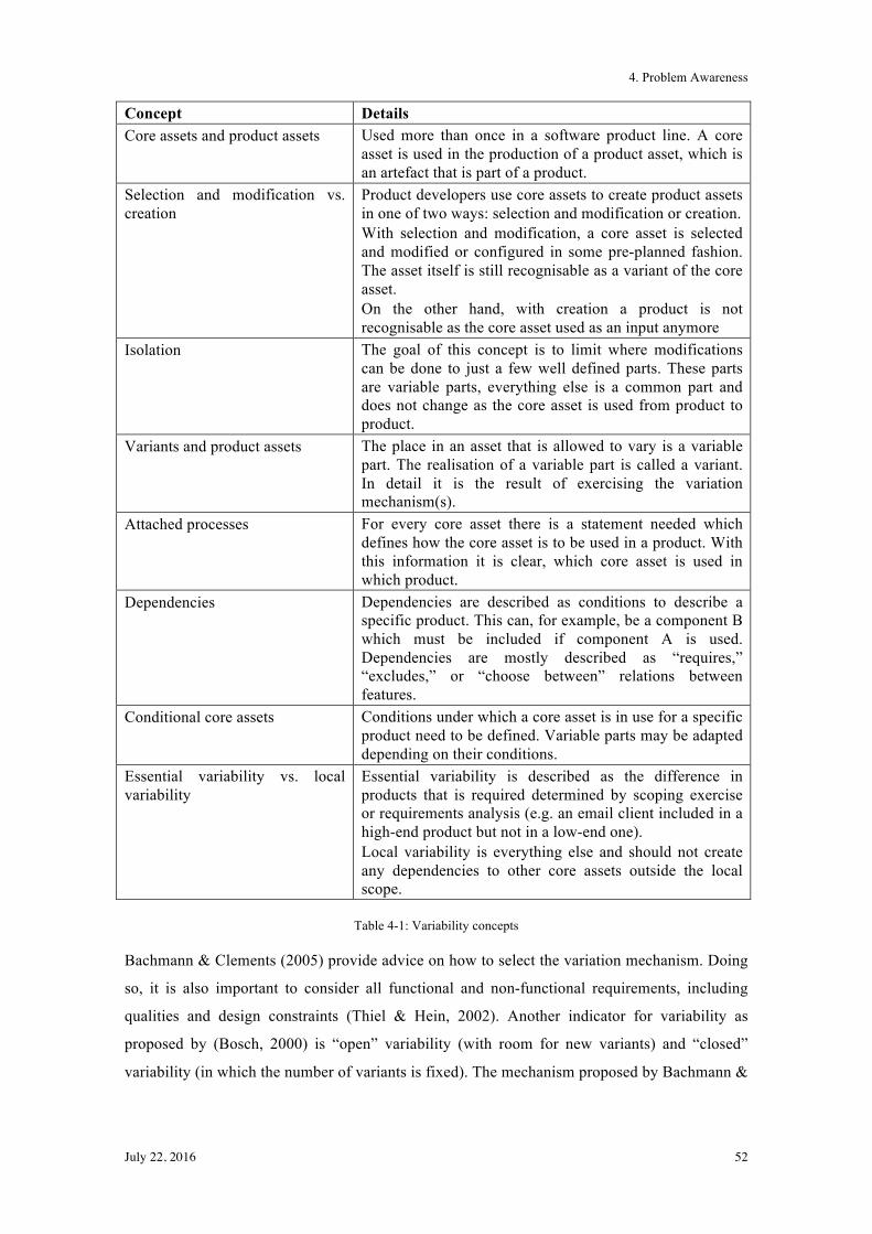
4. Problem Awareness
July 22, 2016 52
Concept Details Core assets and product assets Used more than once in a software product line. A core
asset is used in the production of a product asset, which is an artefact that is part of a product.
Selection and modification vs. creation
Product developers use core assets to create product assets in one of two ways: selection and modification or creation. With selection and modification, a core asset is selected and modified or configured in some pre-planned fashion. The asset itself is still recognisable as a variant of the core asset. On the other hand, with creation a product is not recognisable as the core asset used as an input anymore
Isolation The goal of this concept is to limit where modifications can be done to just a few well defined parts. These parts are variable parts, everything else is a common part and does not change as the core asset is used from product to product.
Variants and product assets The place in an asset that is allowed to vary is a variable part. The realisation of a variable part is called a variant. In detail it is the result of exercising the variation mechanism(s).
Attached processes For every core asset there is a statement needed which defines how the core asset is to be used in a product. With this information it is clear, which core asset is used in which product.
Dependencies Dependencies are described as conditions to describe a specific product. This can, for example, be a component B which must be included if component A is used. Dependencies are mostly described as “requires,” “excludes,” or “choose between” relations between features.
Conditional core assets Conditions under which a core asset is in use for a specific product need to be defined. Variable parts may be adapted depending on their conditions.
Essential variability vs. local variability
Essential variability is described as the difference in products that is required determined by scoping exercise or requirements analysis (e.g. an email client included in a high-end product but not in a low-end one). Local variability is everything else and should not create any dependencies to other core assets outside the local scope.
Table 4-1: Variability concepts
Bachmann & Clements (2005) provide advice on how to select the variation mechanism. Doing
so, it is also important to consider all functional and non-functional requirements, including
qualities and design constraints (Thiel & Hein, 2002). Another indicator for variability as
proposed by (Bosch, 2000) is “open” variability (with room for new variants) and “closed”
variability (in which the number of variants is fixed). The mechanism proposed by Bachmann &
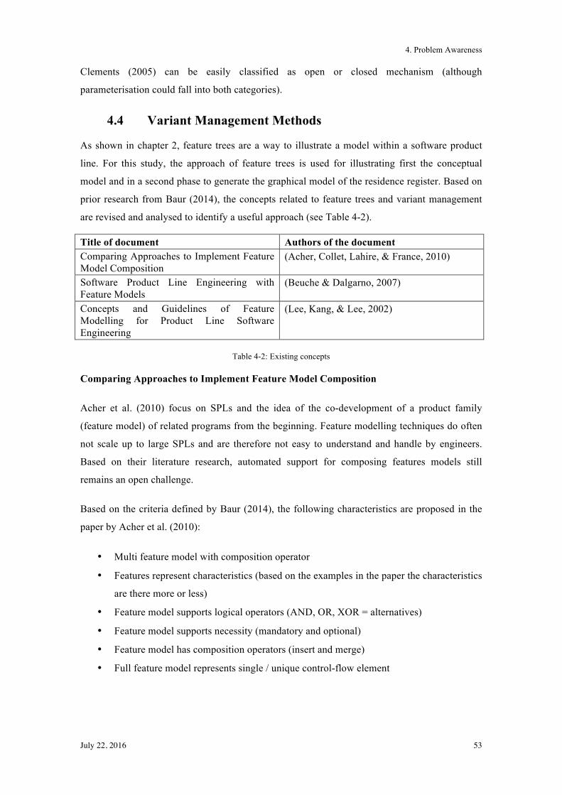
4. Problem Awareness
July 22, 2016 53
Clements (2005) can be easily classified as open or closed mechanism (although
parameterisation could fall into both categories).
4.4 Variant Management Methods
As shown in chapter 2, feature trees are a way to illustrate a model within a software product
line. For this study, the approach of feature trees is used for illustrating first the conceptual
model and in a second phase to generate the graphical model of the residence register. Based on
prior research from Baur (2014), the concepts related to feature trees and variant management
are revised and analysed to identify a useful approach (see Table 4-2).
Title of document Authors of the document Comparing Approaches to Implement Feature Model Composition
(Acher, Collet, Lahire, & France, 2010)
Software Product Line Engineering with Feature Models
(Beuche & Dalgarno, 2007)
Concepts and Guidelines of Feature Modelling for Product Line Software Engineering
(Lee, Kang, & Lee, 2002)
Table 4-2: Existing concepts
Comparing Approaches to Implement Feature Model Composition
Acher et al. (2010) focus on SPLs and the idea of the co-development of a product family
(feature model) of related programs from the beginning. Feature modelling techniques do often
not scale up to large SPLs and are therefore not easy to understand and handle by engineers.
Based on their literature research, automated support for composing features models still
remains an open challenge.
Based on the criteria defined by Baur (2014), the following characteristics are proposed in the
paper by Acher et al. (2010):
• Multi feature model with composition operator
• Features represent characteristics (based on the examples in the paper the characteristics
are there more or less)
• Feature model supports logical operators (AND, OR, XOR = alternatives)
• Feature model supports necessity (mandatory and optional)
• Feature model has composition operators (insert and merge)
• Full feature model represents single / unique control-flow element
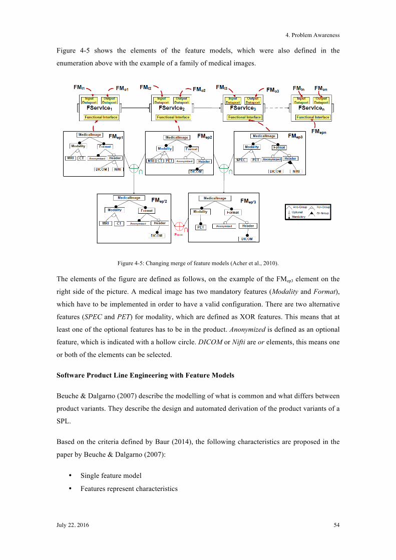
4. Problem Awareness
July 22, 2016 54
Figure 4-5 shows the elements of the feature models, which were also defined in the
enumeration above with the example of a family of medical images.
Figure 4-5: Changing merge of feature models (Acher et al., 2010).
The elements of the figure are defined as follows, on the example of the FMep3 element on the
right side of the picture. A medical image has two mandatory features (Modality and Format),
which have to be implemented in order to have a valid configuration. There are two alternative
features (SPEC and PET) for modality, which are defined as XOR features. This means that at
least one of the optional features has to be in the product. Anonymized is defined as an optional
feature, which is indicated with a hollow circle. DICOM or Nifti are or elements, this means one
or both of the elements can be selected.
Software Product Line Engineering with Feature Models
Beuche & Dalgarno (2007) describe the modelling of what is common and what differs between
product variants. They describe the design and automated derivation of the product variants of a
SPL.
Based on the criteria defined by Baur (2014), the following characteristics are proposed in the
paper by Beuche & Dalgarno (2007):
• Single feature model
• Features represent characteristics
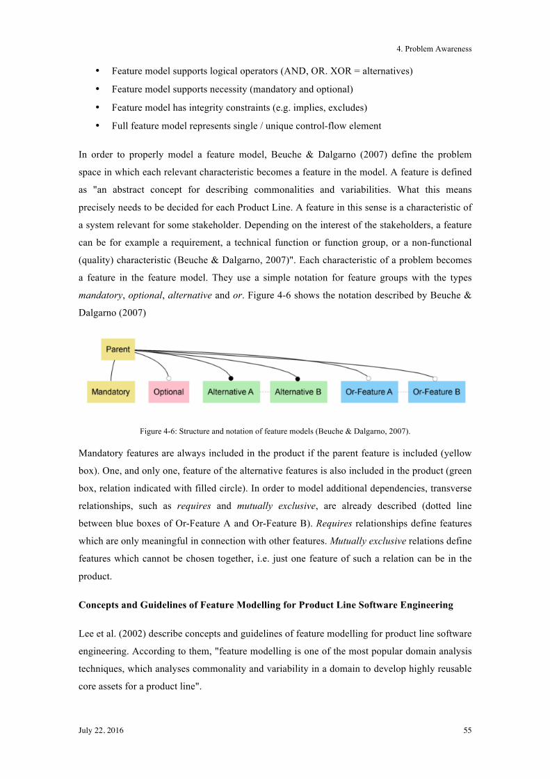
4. Problem Awareness
July 22, 2016 55
• Feature model supports logical operators (AND, OR. XOR = alternatives)
• Feature model supports necessity (mandatory and optional)
• Feature model has integrity constraints (e.g. implies, excludes)
• Full feature model represents single / unique control-flow element
In order to properly model a feature model, Beuche & Dalgarno (2007) define the problem
space in which each relevant characteristic becomes a feature in the model. A feature is defined
as "an abstract concept for describing commonalities and variabilities. What this means
precisely needs to be decided for each Product Line. A feature in this sense is a characteristic of
a system relevant for some stakeholder. Depending on the interest of the stakeholders, a feature
can be for example a requirement, a technical function or function group, or a non-functional
(quality) characteristic (Beuche & Dalgarno, 2007)". Each characteristic of a problem becomes
a feature in the feature model. They use a simple notation for feature groups with the types
mandatory, optional, alternative and or. Figure 4-6 shows the notation described by Beuche &
Dalgarno (2007)
Figure 4-6: Structure and notation of feature models (Beuche & Dalgarno, 2007).
Mandatory features are always included in the product if the parent feature is included (yellow
box). One, and only one, feature of the alternative features is also included in the product (green
box, relation indicated with filled circle). In order to model additional dependencies, transverse
relationships, such as requires and mutually exclusive, are already described (dotted line
between blue boxes of Or-Feature A and Or-Feature B). Requires relationships define features
which are only meaningful in connection with other features. Mutually exclusive relations define
features which cannot be chosen together, i.e. just one feature of such a relation can be in the
product.
Concepts and Guidelines of Feature Modelling for Product Line Software Engineering
Lee et al. (2002) describe concepts and guidelines of feature modelling for product line software
engineering. According to them, "feature modelling is one of the most popular domain analysis
techniques, which analyses commonality and variability in a domain to develop highly reusable
core assets for a product line".
4. Problem Awareness
July 22, 2016 56
Based on the criteria defined by Baur (2014), the following characteristics are proposed in the
paper by (Lee et al., 2002):
• Single feature model
• Features represent characteristics
• Feature model supports logical operators (AND, OR. XOR = alternatives)
• Feature model supports necessity (mandatory and optional)
• Full feature model represents single / unique control-flow element
According to Lee et al. (2002), the focus in feature modelling should be laid on identifying
commonality and variability in a domain based on identifying externally visible characteristics
of products. They define several reasons why feature-oriented domain analysis has been used
extensively compared to other domain analysis techniques:
• Communication: it is an effective communication "medium" among different
stakeholders. Customers and engineers often speak of product characteristics in terms of
"features the product has/or delivers" and discuss requirements or functions in terms of
features. These are essential abstractions which both, customers and engineers,
understand in the same way
• Variability: feature-oriented domain analysis is an effective way to identify variability
and commonality among different products in a domain. The term ”feature” is used
naturally and intuitively to express variability.
• Basis: the feature model can provide a basis for developing, parameterising and
configuring various reusable assets. The model plays a central role in the development
of reusable assets and also in the management and configuration of multiple products in
a domain.
In summary, the paper describes the definitions (feature, feature model, languages etc.) and the
extensions of feature-oriented domain analysis and recommends guidelines. The guidelines
include domain planning, feature identification, feature organisation and feature refinement.
For this thesis, a feature is defined as a specific functionality provided by the software, which
has been examined in the motivation scenarios (chapter 4.2.1) and will be modelled in a tree
structure. Since (Lee et al., 2002) conclude, "feature modelling is intuitive, efficient, and
effective for identifying commonality and variability of applications in a domain. The feature
model is a good communication media among those who have different concerns in application
development", the used approach for this thesis are feature trees and feature models to handle
variability in software. This decision has been taken based on the experience gained from the
4. Problem Awareness
July 22, 2016 57
research in the area of software product lines and because it is a well-known approach for
illustrating variants in software.
4.5 Summary
In the awareness phase, three applications and their corresponding problems are considered in
order to obtain a broader view and derive a good set of competency questions. In the next phase
only one application, residence register (RREG), will be considered. The three applications
observed in the awareness phase are independent from each other considering all information
and requirements.
As public administrations have their own influencers on variants, an overview on them and their
causes has been derived based on the interviews. These influencers have a major effect on the
software and the corresponding; they will be also a key aspect in the next chapters.
In the last section, existing approaches have been considered in order to identify the proper
visual representation of software variants. Several papers propose feature trees/feature models
for representing variability in software. Therefore, this approach will be employed in the next
chapters in order to illustrate the software variants of the residence register.
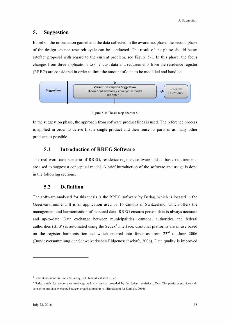
5. Suggestion
July 22, 2016 58
5. Suggestion
Based on the information gained and the data collected in the awareness phase, the second phase
of the design science research cycle can be conducted. The result of the phase should be an
artefact proposal with regard to the current problem, see Figure 5-1. In this phase, the focus
changes from three applications to one. Just data and requirements from the residence register
(RREG) are considered in order to limit the amount of data to be modelled and handled.
Figure 5-1: Thesis map chapter 5.
In the suggestion phase, the approach from software product lines is used. The reference process
is applied in order to derive first a single product and then reuse its parts in as many other
products as possible.
5.1 Introduction of RREG Software
The real-word case scenario of RREG, residence register, software and its basic requirements
are used to suggest a conceptual model. A brief introduction of the software and usage is done
in the following sections.
5.2 Definition
The software analysed for this thesis is the RREG software by Bedag, which is located in the
Geres-environment. It is an application used by 16 cantons in Switzerland, which offers the
management and harmonisation of personal data. RREG ensures person data is always accurate
and up-to-date. Data exchange between municipalities, cantonal authorities and federal
authorities (BFS2) is automated using the Sedex3 interface. Cantonal platforms are in use based
on the register harmonisation act which entered into force as from 23rd of June 2006
(Bundesversammlung der Schweizerischen Eidgenossenschaft, 2006). Data quality is improved
2 BFS: Bundesamt für Statistik, in Englisch: federal statistics office 3 Sedex:stands for secure data exchange and is a service provided by the federal statistics office. The platform provides safe
asynchronous data exchange between organisational units. (Bundesamt für Statistik, 2016)
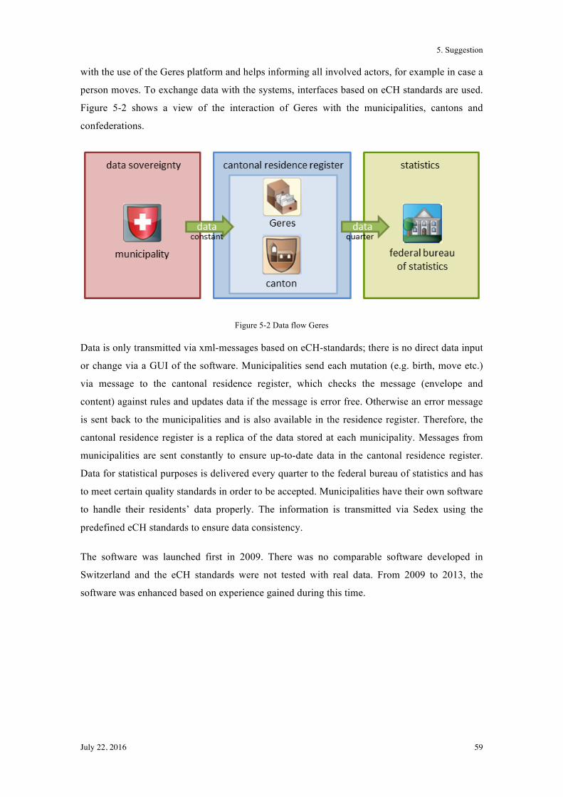
5. Suggestion
July 22, 2016 59
with the use of the Geres platform and helps informing all involved actors, for example in case a
person moves. To exchange data with the systems, interfaces based on eCH standards are used.
Figure 5-2 shows a view of the interaction of Geres with the municipalities, cantons and
confederations.
Figure 5-2 Data flow Geres
Data is only transmitted via xml-messages based on eCH-standards; there is no direct data input
or change via a GUI of the software. Municipalities send each mutation (e.g. birth, move etc.)
via message to the cantonal residence register, which checks the message (envelope and
content) against rules and updates data if the message is error free. Otherwise an error message
is sent back to the municipalities and is also available in the residence register. Therefore, the
cantonal residence register is a replica of the data stored at each municipality. Messages from
municipalities are sent constantly to ensure up-to-date data in the cantonal residence register.
Data for statistical purposes is delivered every quarter to the federal bureau of statistics and has
to meet certain quality standards in order to be accepted. Municipalities have their own software
to handle their residents’ data properly. The information is transmitted via Sedex using the
predefined eCH standards to ensure data consistency.
The software was launched first in 2009. There was no comparable software developed in
Switzerland and the eCH standards were not tested with real data. From 2009 to 2013, the
software was enhanced based on experience gained during this time.
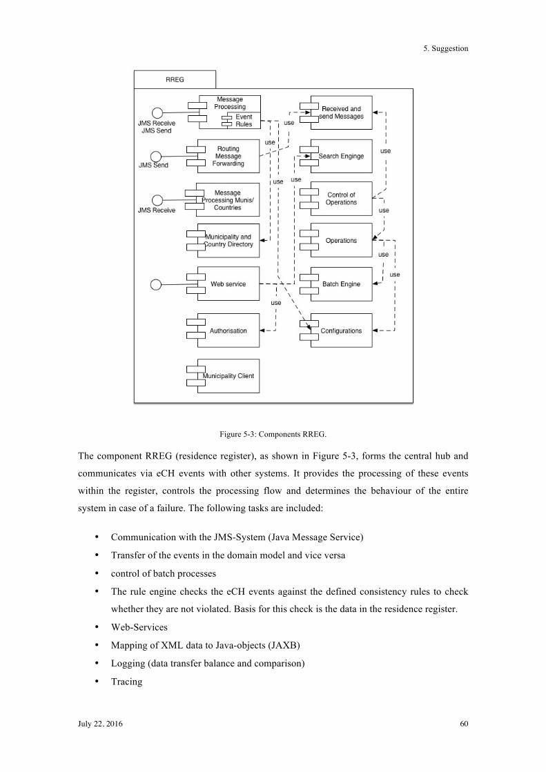
5. Suggestion
July 22, 2016 60
Figure 5-3: Components RREG.
The component RREG (residence register), as shown in Figure 5-3, forms the central hub and
communicates via eCH events with other systems. It provides the processing of these events
within the register, controls the processing flow and determines the behaviour of the entire
system in case of a failure. The following tasks are included:
• Communication with the JMS-System (Java Message Service)
• Transfer of the events in the domain model and vice versa
• control of batch processes
• The rule engine checks the eCH events against the defined consistency rules to check
whether they are not violated. Basis for this check is the data in the residence register.
• Web-Services
• Mapping of XML data to Java-objects (JAXB)
• Logging (data transfer balance and comparison)
• Tracing
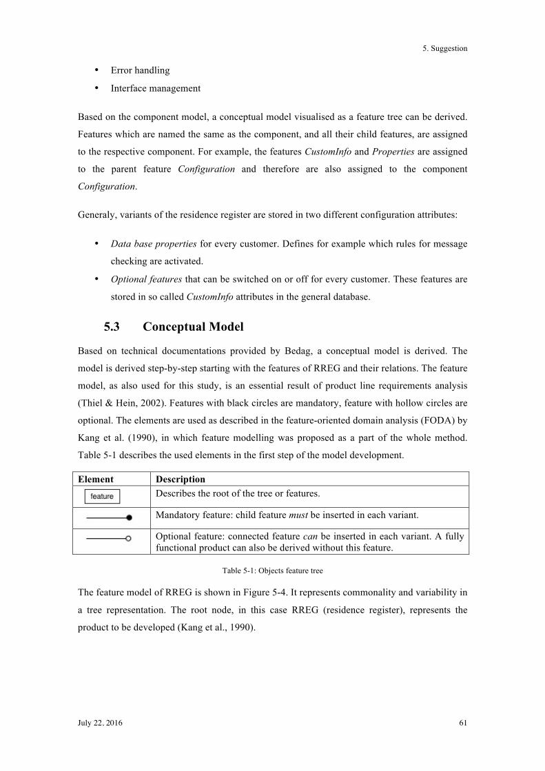
5. Suggestion
July 22, 2016 61
• Error handling
• Interface management
Based on the component model, a conceptual model visualised as a feature tree can be derived.
Features which are named the same as the component, and all their child features, are assigned
to the respective component. For example, the features CustomInfo and Properties are assigned
to the parent feature Configuration and therefore are also assigned to the component
Configuration.
Generaly, variants of the residence register are stored in two different configuration attributes:
• Data base properties for every customer. Defines for example which rules for message
checking are activated.
• Optional features that can be switched on or off for every customer. These features are
stored in so called CustomInfo attributes in the general database.
5.3 Conceptual Model
Based on technical documentations provided by Bedag, a conceptual model is derived. The
model is derived step-by-step starting with the features of RREG and their relations. The feature
model, as also used for this study, is an essential result of product line requirements analysis
(Thiel & Hein, 2002). Features with black circles are mandatory, feature with hollow circles are
optional. The elements are used as described in the feature-oriented domain analysis (FODA) by
Kang et al. (1990), in which feature modelling was proposed as a part of the whole method.
Table 5-1 describes the used elements in the first step of the model development.
Element Description
Describes the root of the tree or features.
Mandatory feature: child feature must be inserted in each variant.
Optional feature: connected feature can be inserted in each variant. A fully functional product can also be derived without this feature.
Table 5-1: Objects feature tree
The feature model of RREG is shown in Figure 5-4. It represents commonality and variability in
a tree representation. The root node, in this case RREG (residence register), represents the
product to be developed (Kang et al., 1990).
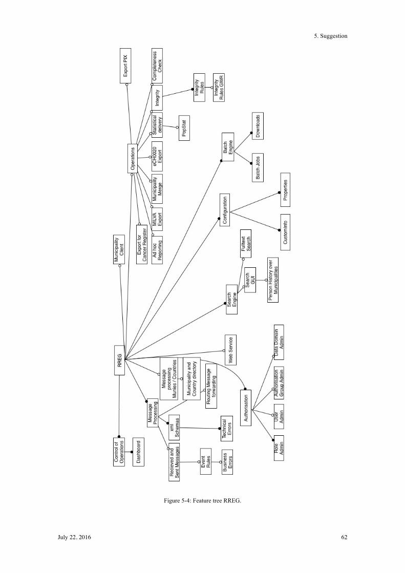
5. Suggestion
July 22, 2016 62
Figure 5-4: Feature tree RREG.
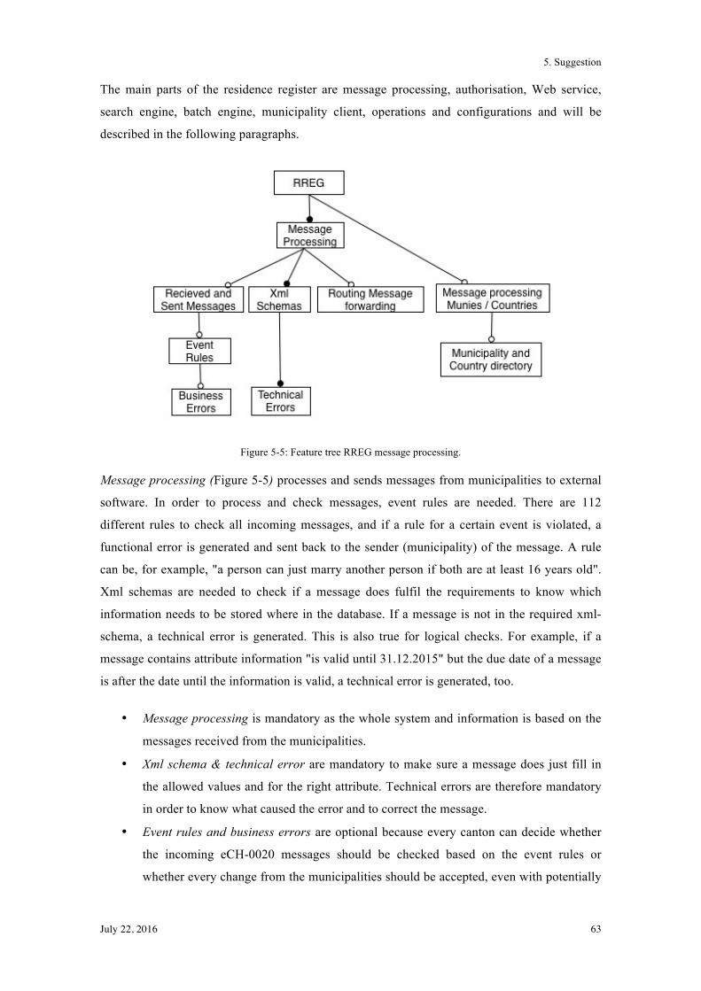
5. Suggestion
July 22, 2016 63
The main parts of the residence register are message processing, authorisation, Web service,
search engine, batch engine, municipality client, operations and configurations and will be
described in the following paragraphs.
Figure 5-5: Feature tree RREG message processing.
Message processing (Figure 5-5) processes and sends messages from municipalities to external
software. In order to process and check messages, event rules are needed. There are 112
different rules to check all incoming messages, and if a rule for a certain event is violated, a
functional error is generated and sent back to the sender (municipality) of the message. A rule
can be, for example, "a person can just marry another person if both are at least 16 years old".
Xml schemas are needed to check if a message does fulfil the requirements to know which
information needs to be stored where in the database. If a message is not in the required xml-
schema, a technical error is generated. This is also true for logical checks. For example, if a
message contains attribute information "is valid until 31.12.2015" but the due date of a message
is after the date until the information is valid, a technical error is generated, too.
• Message processing is mandatory as the whole system and information is based on the
messages received from the municipalities.
• Xml schema & technical error are mandatory to make sure a message does just fill in
the allowed values and for the right attribute. Technical errors are therefore mandatory
in order to know what caused the error and to correct the message.
• Event rules and business errors are optional because every canton can decide whether
the incoming eCH-0020 messages should be checked based on the event rules or
whether every change from the municipalities should be accepted, even with potentially
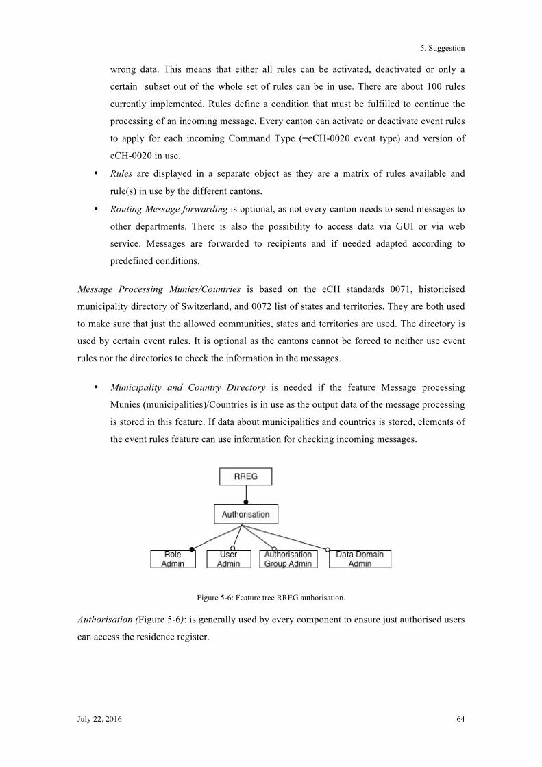
5. Suggestion
July 22, 2016 64
wrong data. This means that either all rules can be activated, deactivated or only a
certain subset out of the whole set of rules can be in use. There are about 100 rules
currently implemented. Rules define a condition that must be fulfilled to continue the
processing of an incoming message. Every canton can activate or deactivate event rules
to apply for each incoming Command Type (=eCH-0020 event type) and version of
eCH-0020 in use.
• Rules are displayed in a separate object as they are a matrix of rules available and
rule(s) in use by the different cantons.
• Routing Message forwarding is optional, as not every canton needs to send messages to
other departments. There is also the possibility to access data via GUI or via web
service. Messages are forwarded to recipients and if needed adapted according to
predefined conditions.
Message Processing Munies/Countries is based on the eCH standards 0071, historicised
municipality directory of Switzerland, and 0072 list of states and territories. They are both used
to make sure that just the allowed communities, states and territories are used. The directory is
used by certain event rules. It is optional as the cantons cannot be forced to neither use event
rules nor the directories to check the information in the messages.
• Municipality and Country Directory is needed if the feature Message processing
Munies (municipalities)/Countries is in use as the output data of the message processing
is stored in this feature. If data about municipalities and countries is stored, elements of
the event rules feature can use information for checking incoming messages.
Figure 5-6: Feature tree RREG authorisation.
Authorisation (Figure 5-6): is generally used by every component to ensure just authorised users
can access the residence register.
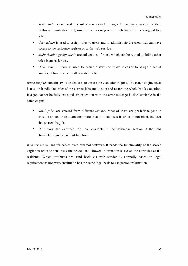
5. Suggestion
July 22, 2016 65
• Role admin is used to define roles, which can be assigned to as many users as needed.
In this administration part, single attributes or groups of attributes can be assigned to a
role.
• User admin is used to assign roles to users and to administrate the users that can have
access to the residence register or to the web service.
• Authorisation group admin are collections of roles, which can be reused to define other
roles in an easier way.
• Data domain admin is used to define districts to make it easier to assign a set of
municipalities to a user with a certain role.
Batch Engine: contains two sub-features to ensure the execution of jobs. The Batch engine itself
is used to handle the order of the current jobs and to stop and restart the whole batch execution.
If a job cannot be fully executed, an exception with the error message is also available in the
batch engine.
• Batch jobs: are created from different actions. Most of them are predefined jobs to
execute an action that contains more than 100 data sets in order to not block the user
that started the job.
• Download: the executed jobs are available in the download section if the jobs
themselves have an output function.
Web service is used for access from external software. It needs the functionality of the search
engine in order to send back the needed and allowed information based on the attributes of the
residents. Which attributes are send back via web service is normally based on legal
requirement as not every institution has the same legal basis to use person information.
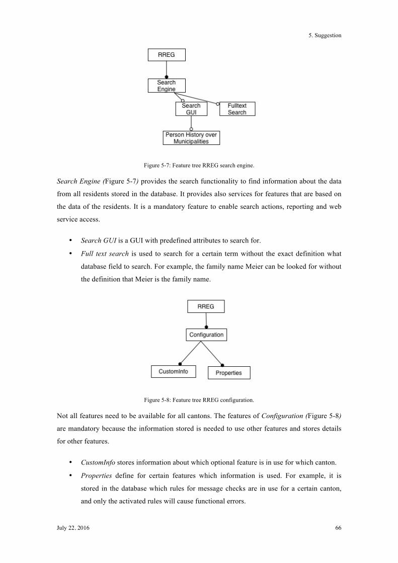
5. Suggestion
July 22, 2016 66
Figure 5-7: Feature tree RREG search engine.
Search Engine (Figure 5-7) provides the search functionality to find information about the data
from all residents stored in the database. It provides also services for features that are based on
the data of the residents. It is a mandatory feature to enable search actions, reporting and web
service access.
• Search GUI is a GUI with predefined attributes to search for.
• Full text search is used to search for a certain term without the exact definition what
database field to search. For example, the family name Meier can be looked for without
the definition that Meier is the family name.
Figure 5-8: Feature tree RREG configuration.
Not all features need to be available for all cantons. The features of Configuration (Figure 5-8)
are mandatory because the information stored is needed to use other features and stores details
for other features.
• CustomInfo stores information about which optional feature is in use for which canton.
• Properties define for certain features which information is used. For example, it is
stored in the database which rules for message checks are in use for a certain canton,
and only the activated rules will cause functional errors.
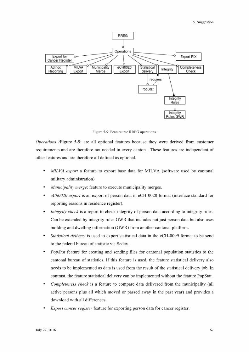
5. Suggestion
July 22, 2016 67
Figure 5-9: Feature tree RREG operations.
Operations (Figure 5-9: are all optional features because they were derived from customer
requirements and are therefore not needed in every canton. These features are independent of
other features and are therefore all defined as optional.
• MILVA export a feature to export base data for MILVA (software used by cantonal
military administration)
• Municipality merge: feature to execute municipality merges.
• eCh0020 export is an export of person data in eCH-0020 format (interface standard for
reporting reasons in residence register).
• Integrity check is a report to check integrity of person data according to integrity rules.
Can be extended by integrity rules GWR that includes not just person data but also uses
building and dwelling information (GWR) from another cantonal platform.
• Statistical delivery is used to export statistical data in the eCH-0099 format to be send
to the federal bureau of statistic via Sedex.
• PopStat feature for creating and sending files for cantonal population statistics to the
cantonal bureau of statistics. If this feature is used, the feature statistical delivery also
needs to be implemented as data is used from the result of the statistical delivery job. In
contrast, the feature statistical delivery can be implemented without the feature PopStat.
• Completeness check is a feature to compare data delivered from the municipality (all
active persons plus all which moved or passed away in the past year) and provides a
download with all differences.
• Export cancer register feature for exporting person data for cancer register.
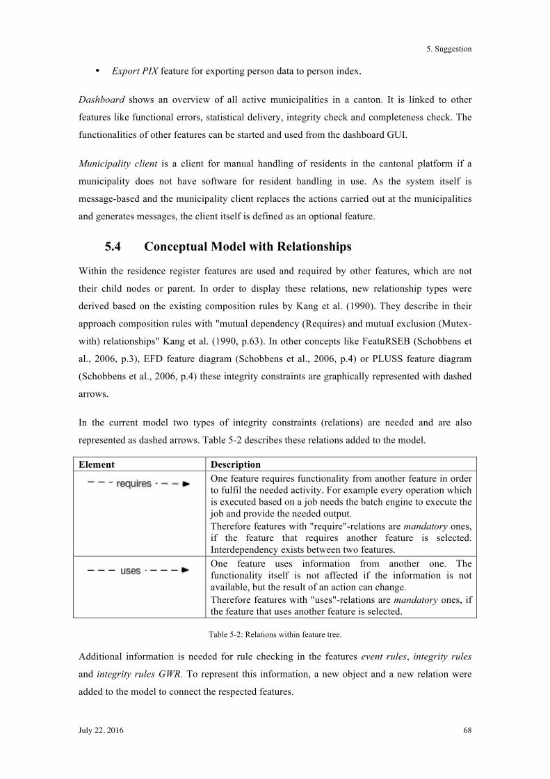
5. Suggestion
July 22, 2016 68
• Export PIX feature for exporting person data to person index.
Dashboard shows an overview of all active municipalities in a canton. It is linked to other
features like functional errors, statistical delivery, integrity check and completeness check. The
functionalities of other features can be started and used from the dashboard GUI.
Municipality client is a client for manual handling of residents in the cantonal platform if a
municipality does not have software for resident handling in use. As the system itself is
message-based and the municipality client replaces the actions carried out at the municipalities
and generates messages, the client itself is defined as an optional feature.
5.4 Conceptual Model with Relationships
Within the residence register features are used and required by other features, which are not
their child nodes or parent. In order to display these relations, new relationship types were
derived based on the existing composition rules by Kang et al. (1990). They describe in their
approach composition rules with "mutual dependency (Requires) and mutual exclusion (Mutex-
with) relationships" Kang et al. (1990, p.63). In other concepts like FeatuRSEB (Schobbens et
al., 2006, p.3), EFD feature diagram (Schobbens et al., 2006, p.4) or PLUSS feature diagram
(Schobbens et al., 2006, p.4) these integrity constraints are graphically represented with dashed
arrows.
In the current model two types of integrity constraints (relations) are needed and are also
represented as dashed arrows. Table 5-2 describes these relations added to the model.
Element Description
One feature requires functionality from another feature in order to fulfil the needed activity. For example every operation which is executed based on a job needs the batch engine to execute the job and provide the needed output. Therefore features with "require"-relations are mandatory ones, if the feature that requires another feature is selected. Interdependency exists between two features.
One feature uses information from another one. The functionality itself is not affected if the information is not available, but the result of an action can change. Therefore features with "uses"-relations are mandatory ones, if the feature that uses another feature is selected.
Table 5-2: Relations within feature tree.
Additional information is needed for rule checking in the features event rules, integrity rules
and integrity rules GWR. To represent this information, a new object and a new relation were
added to the model to connect the respected features.
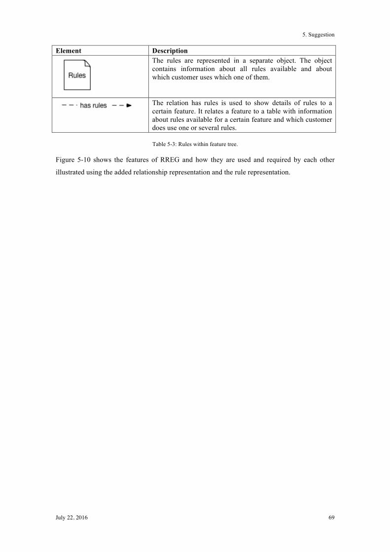
5. Suggestion
July 22, 2016 69
Element Description
The rules are represented in a separate object. The object contains information about all rules available and about which customer uses which one of them.
The relation has rules is used to show details of rules to a certain feature. It relates a feature to a table with information about rules available for a certain feature and which customer does use one or several rules.
Table 5-3: Rules within feature tree.
Figure 5-10 shows the features of RREG and how they are used and required by each other
illustrated using the added relationship representation and the rule representation.

5. Suggestion
July 22, 2016 70
Figure 5-10: Feature tree RREG with requirements and usage.
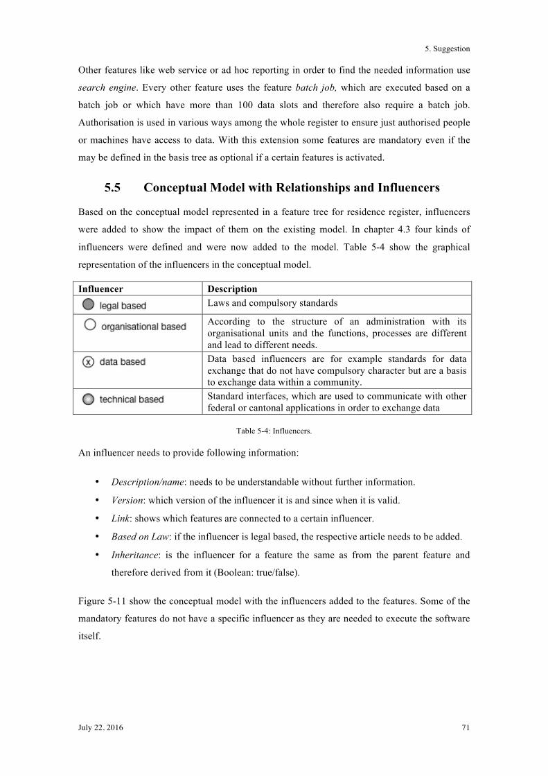
5. Suggestion
July 22, 2016 71
Other features like web service or ad hoc reporting in order to find the needed information use
search engine. Every other feature uses the feature batch job, which are executed based on a
batch job or which have more than 100 data slots and therefore also require a batch job.
Authorisation is used in various ways among the whole register to ensure just authorised people
or machines have access to data. With this extension some features are mandatory even if the
may be defined in the basis tree as optional if a certain features is activated.
5.5 Conceptual Model with Relationships and Influencers
Based on the conceptual model represented in a feature tree for residence register, influencers
were added to show the impact of them on the existing model. In chapter 4.3 four kinds of
influencers were defined and were now added to the model. Table 5-4 show the graphical
representation of the influencers in the conceptual model.
Influencer Description
Laws and compulsory standards
According to the structure of an administration with its organisational units and the functions, processes are different and lead to different needs.
Data based influencers are for example standards for data exchange that do not have compulsory character but are a basis to exchange data within a community.
Standard interfaces, which are used to communicate with other federal or cantonal applications in order to exchange data
Table 5-4: Influencers.
An influencer needs to provide following information:
• Description/name: needs to be understandable without further information.
• Version: which version of the influencer it is and since when it is valid.
• Link: shows which features are connected to a certain influencer.
• Based on Law: if the influencer is legal based, the respective article needs to be added.
• Inheritance: is the influencer for a feature the same as from the parent feature and
therefore derived from it (Boolean: true/false).
Figure 5-11 show the conceptual model with the influencers added to the features. Some of the
mandatory features do not have a specific influencer as they are needed to execute the software
itself.
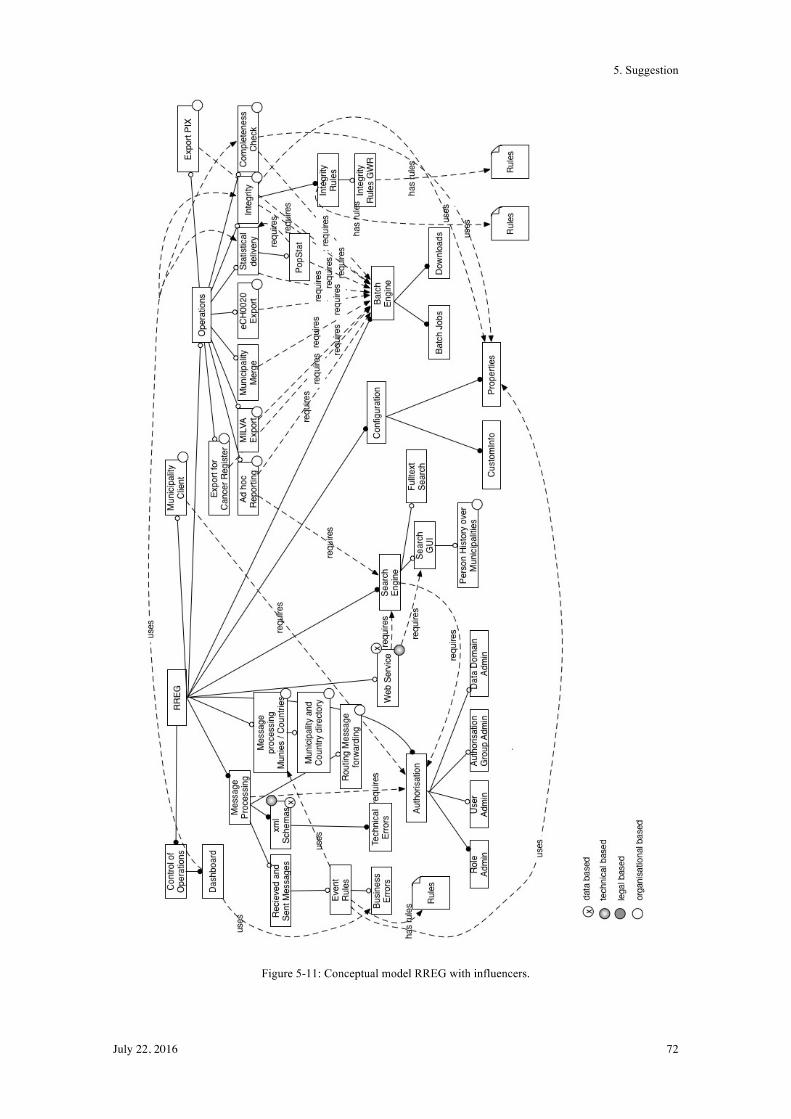
5. Suggestion
July 22, 2016 72
Figure 5-11: Conceptual model RREG with influencers.

5. Suggestion
July 22, 2016 73
5.6 Summary
In chapter 5 the conceptual model based on the RREG application is derived as a feature tree
with the respected adaptions to visualise the current problem in handling variants. As seen
through the development process, feature tree approaches from current literature do not fully
satisfy the current need for relations between features and especially not the role of influencers.
Therefore in the last step of the model development influencers were graphically added to the
model based on the results from the interviews regarding the type of influencers. The results
from the conceptual model are now used to derive a graphical representation in ADOxx based
on feature trees with the needed extensions.
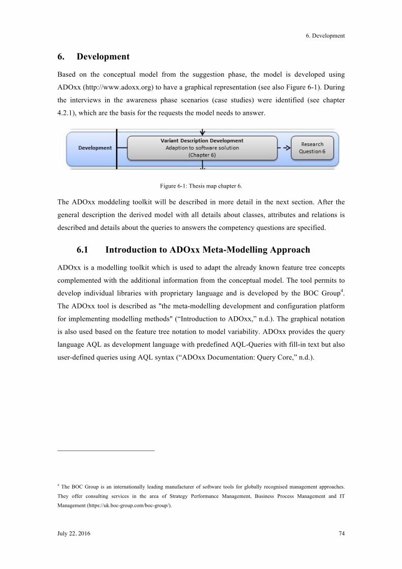
6. Development
July 22, 2016 74
6. Development
Based on the conceptual model from the suggestion phase, the model is developed using
ADOxx (http://www.adoxx.org) to have a graphical representation (see also Figure 6-1). During
the interviews in the awareness phase scenarios (case studies) were identified (see chapter
4.2.1), which are the basis for the requests the model needs to answer.
Figure 6-1: Thesis map chapter 6.
The ADOxx moddeling toolkit will be described in more detail in the next section. After the
general description the derived model with all details about classes, attributes and relations is
described and details about the queries to answers the competency questions are specified.
6.1 Introduction to ADOxx Meta-Modelling Approach
ADOxx is a modelling toolkit which is used to adapt the already known feature tree concepts
complemented with the additional information from the conceptual model. The tool permits to
develop individual libraries with proprietary language and is developed by the BOC Group4.
The ADOxx tool is described as "the meta-modelling development and configuration platform
for implementing modelling methods" (“Introduction to ADOxx,” n.d.). The graphical notation
is also used based on the feature tree notation to model variability. ADOxx provides the query
language AQL as development language with predefined AQL-Queries with fill-in text but also
user-defined queries using AQL syntax (“ADOxx Documentation: Query Core,” n.d.).
4 The BOC Group is an internationally leading manufacturer of software tools for globally recognised management approaches.
They offer consulting services in the area of Strategy Performance Management, Business Process Management and IT
Management (https://uk.boc-group.com/boc-group/).
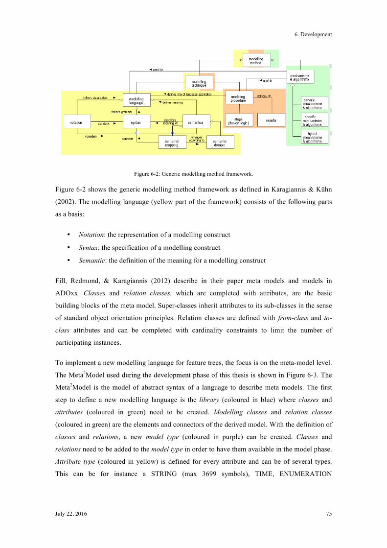
6. Development
July 22, 2016 75
Figure 6-2: Generic modelling method framework.
Figure 6-2 shows the generic modelling method framework as defined in Karagiannis & Kühn
(2002). The modelling language (yellow part of the framework) consists of the following parts
as a basis:
• Notation: the representation of a modelling construct
• Syntax: the specification of a modelling construct
• Semantic: the definition of the meaning for a modelling construct
Fill, Redmond, & Karagiannis (2012) describe in their paper meta models and models in
ADOxx. Classes and relation classes, which are completed with attributes, are the basic
building blocks of the meta model. Super-classes inherit attributes to its sub-classes in the sense
of standard object orientation principles. Relation classes are defined with from-class and to-
class attributes and can be completed with cardinality constraints to limit the number of
participating instances.
To implement a new modelling language for feature trees, the focus is on the meta-model level.
The Meta2Model used during the development phase of this thesis is shown in Figure 6-3. The
Meta2Model is the model of abstract syntax of a language to describe meta models. The first
step to define a new modelling language is the library (coloured in blue) where classes and
attributes (coloured in green) need to be created. Modelling classes and relation classes
(coloured in green) are the elements and connectors of the derived model. With the definition of
classes and relations, a new model type (coloured in purple) can be created. Classes and
relations need to be added to the model type in order to have them available in the model phase.
Attribute type (coloured in yellow) is defined for every attribute and can be of several types.
This can be for instance a STRING (max 3699 symbols), TIME, ENUMERATION
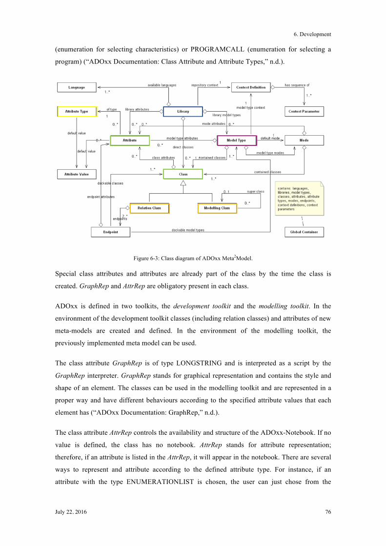
6. Development
July 22, 2016 76
(enumeration for selecting characteristics) or PROGRAMCALL (enumeration for selecting a
program) (“ADOxx Documentation: Class Attribute and Attribute Types,” n.d.).
Figure 6-3: Class diagram of ADOxx Meta2Model.
Special class attributes and attributes are already part of the class by the time the class is
created. GraphRep and AttrRep are obligatory present in each class.
ADOxx is defined in two toolkits, the development toolkit and the modelling toolkit. In the
environment of the development toolkit classes (including relation classes) and attributes of new
meta-models are created and defined. In the environment of the modelling toolkit, the
previously implemented meta model can be used.
The class attribute GraphRep is of type LONGSTRING and is interpreted as a script by the
GraphRep interpreter. GraphRep stands for graphical representation and contains the style and
shape of an element. The classes can be used in the modelling toolkit and are represented in a
proper way and have different behaviours according to the specified attribute values that each
element has (“ADOxx Documentation: GraphRep,” n.d.).
The class attribute AttrRep controls the availability and structure of the ADOxx-Notebook. If no
value is defined, the class has no notebook. AttrRep stands for attribute representation;
therefore, if an attribute is listed in the AttrRep, it will appear in the notebook. There are several
ways to represent and attribute according to the defined attribute type. For instance, if an
attribute with the type ENUMERATIONLIST is chosen, the user can just chose from the
6. Development
July 22, 2016 77
predefined values. Another example is the type INTERREF, where the user has the possibility
to associate to the class a model or an instance (“ADOxx Documentation: AttrRep,” n.d.).
Relationships are named relations between classes and are defined by their source and target
class, their cardinality and their attributes. Any class can act as source class (where the relation
starts) and as a target class (where the relation ends). Their role is a different one than the other
classes, as they connect modelling elements and they can be seen as connectors. In the
GraphRep it can be defined on which classes the connector is allowed to attach or not (“ADOxx
Documentation: Relations in ADOxx,” n.d.).
In order to answer the competency question, the ADOxx development language AQL is used.
Extended Bakus Naur Form (EBNF) notation is use for describing AQL syntax (“ADOxx
Development Language: AQL,” n.d.). The queries used to find the needed information are noted
with every competency question.
6.2 Graphical Model
The new model I propose in this chapter is based on elements of a feature tree. The idea beyond
the new model is based on the extension of the feature tree for instance with additional relation
"uses" or the addition of influencers to the features.
In the following sections classes, attributes and relations used to model the problem are
described in detail. Figure 6-4 shows a part of the feature tree of the residence register to give an
impression of the used elements in the model.
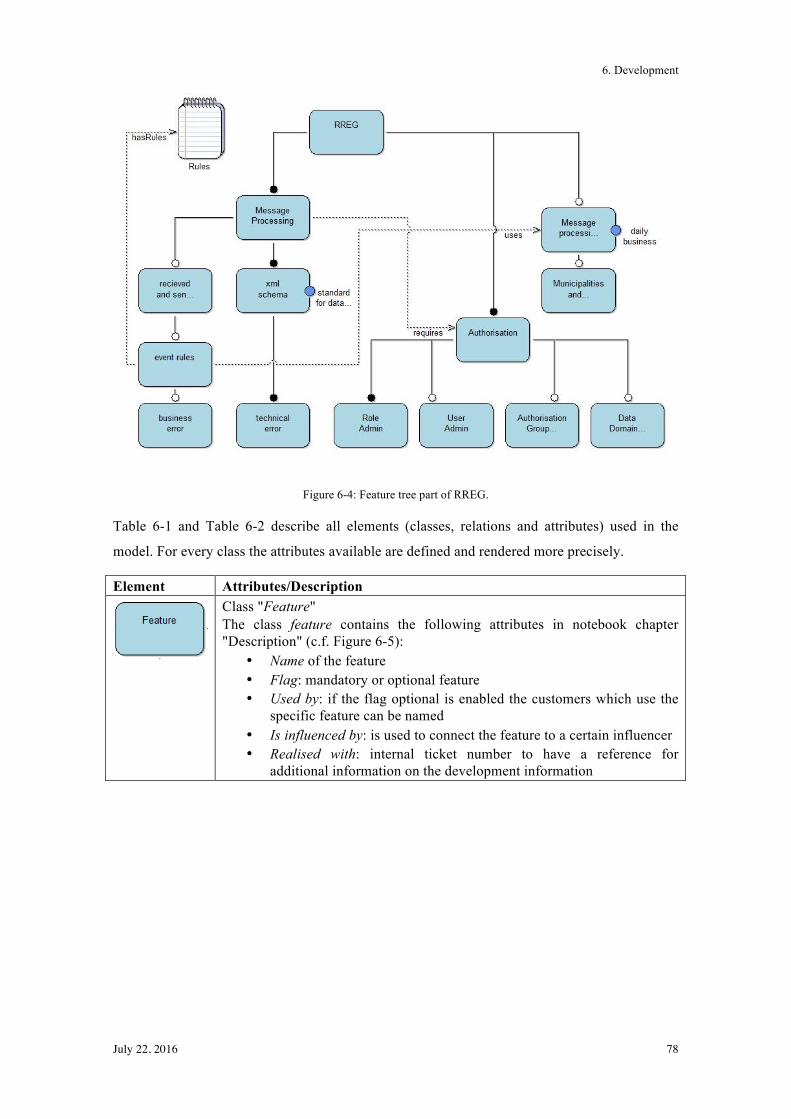
6. Development
July 22, 2016 78
Figure 6-4: Feature tree part of RREG.
Table 6-1 and Table 6-2 describe all elements (classes, relations and attributes) used in the
model. For every class the attributes available are defined and rendered more precisely.
Element Attributes/Description
Class "Feature" The class feature contains the following attributes in notebook chapter "Description" (c.f. Figure 6-5):
• Name of the feature • Flag: mandatory or optional feature • Used by: if the flag optional is enabled the customers which use the
specific feature can be named • Is influenced by: is used to connect the feature to a certain influencer • Realised with: internal ticket number to have a reference for
additional information on the development information
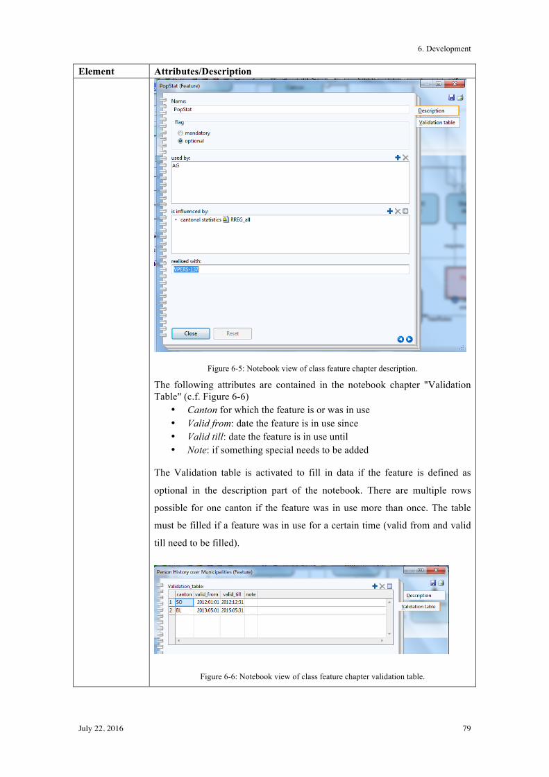
6. Development
July 22, 2016 79
Element Attributes/Description
Figure 6-5: Notebook view of class feature chapter description.
The following attributes are contained in the notebook chapter "Validation Table" (c.f. Figure 6-6)
• Canton for which the feature is or was in use • Valid from: date the feature is in use since • Valid till: date the feature is in use until • Note: if something special needs to be added
The Validation table is activated to fill in data if the feature is defined as
optional in the description part of the notebook. There are multiple rows
possible for one canton if the feature was in use more than once. The table
must be filled if a feature was in use for a certain time (valid from and valid
till need to be filled).
Figure 6-6: Notebook view of class feature chapter validation table.
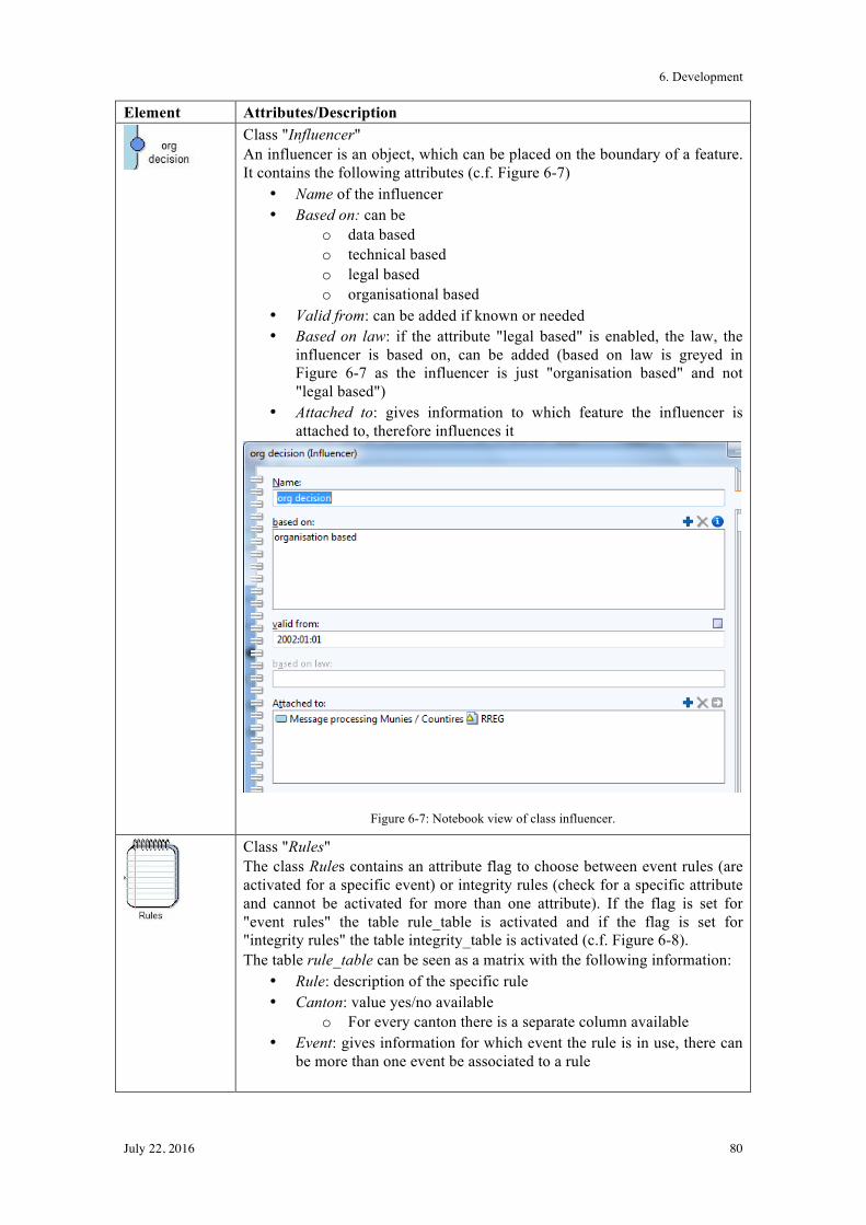
6. Development
July 22, 2016 80
Element Attributes/Description
Class "Influencer" An influencer is an object, which can be placed on the boundary of a feature. It contains the following attributes (c.f. Figure 6-7)
• Name of the influencer • Based on: can be
o data based o technical based o legal based o organisational based
• Valid from: can be added if known or needed • Based on law: if the attribute "legal based" is enabled, the law, the
influencer is based on, can be added (based on law is greyed in Figure 6-7 as the influencer is just "organisation based" and not "legal based")
• Attached to: gives information to which feature the influencer is attached to, therefore influences it
Figure 6-7: Notebook view of class influencer.
Class "Rules" The class Rules contains an attribute flag to choose between event rules (are activated for a specific event) or integrity rules (check for a specific attribute and cannot be activated for more than one attribute). If the flag is set for "event rules" the table rule_table is activated and if the flag is set for "integrity rules" the table integrity_table is activated (c.f. Figure 6-8). The table rule_table can be seen as a matrix with the following information:
• Rule: description of the specific rule • Canton: value yes/no available
o For every canton there is a separate column available • Event: gives information for which event the rule is in use, there can
be more than one event be associated to a rule
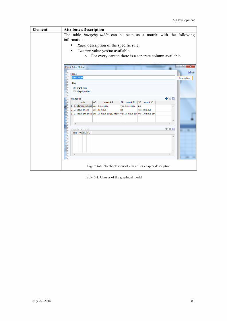
6. Development
July 22, 2016 81
Element Attributes/Description The table integrity_table can be seen as a matrix with the following information:
• Rule: description of the specific rule • Canton: value yes/no available
o For every canton there is a separate column available
Figure 6-8: Notebook view of class rules chapter description.
Table 6-1: Classes of the graphical model
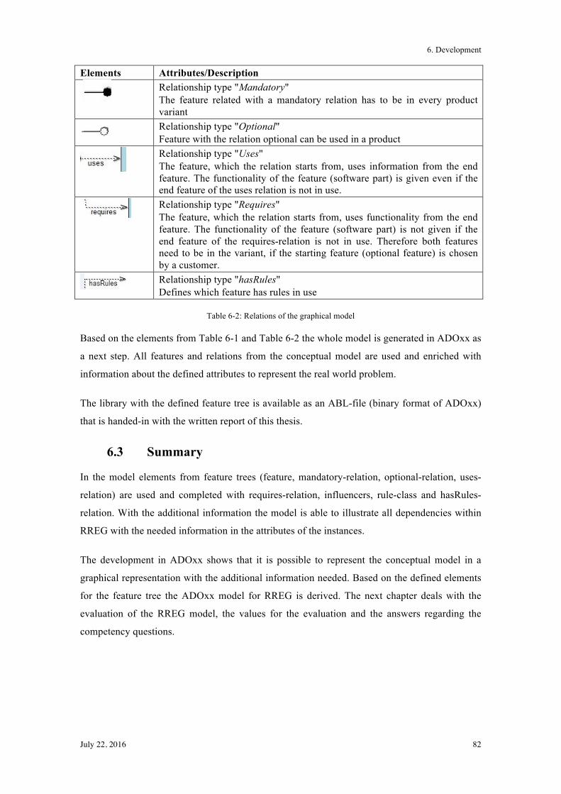
6. Development
July 22, 2016 82
Elements Attributes/Description
Relationship type "Mandatory" The feature related with a mandatory relation has to be in every product variant
Relationship type "Optional" Feature with the relation optional can be used in a product
Relationship type "Uses" The feature, which the relation starts from, uses information from the end feature. The functionality of the feature (software part) is given even if the end feature of the uses relation is not in use.
Relationship type "Requires" The feature, which the relation starts from, uses functionality from the end feature. The functionality of the feature (software part) is not given if the end feature of the requires-relation is not in use. Therefore both features need to be in the variant, if the starting feature (optional feature) is chosen by a customer.
Relationship type "hasRules" Defines which feature has rules in use
Table 6-2: Relations of the graphical model
Based on the elements from Table 6-1 and Table 6-2 the whole model is generated in ADOxx as
a next step. All features and relations from the conceptual model are used and enriched with
information about the defined attributes to represent the real world problem.
The library with the defined feature tree is available as an ABL-file (binary format of ADOxx)
that is handed-in with the written report of this thesis.
6.3 Summary
In the model elements from feature trees (feature, mandatory-relation, optional-relation, uses-
relation) are used and completed with requires-relation, influencers, rule-class and hasRules-
relation. With the additional information the model is able to illustrate all dependencies within
RREG with the needed information in the attributes of the instances.
The development in ADOxx shows that it is possible to represent the conceptual model in a
graphical representation with the additional information needed. Based on the defined elements
for the feature tree the ADOxx model for RREG is derived. The next chapter deals with the
evaluation of the RREG model, the values for the evaluation and the answers regarding the
competency questions.
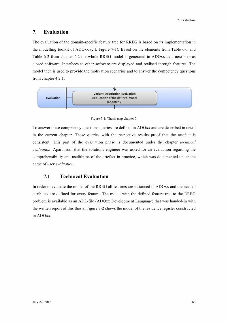
7. Evaluation
July 22, 2016 83
7. Evaluation
The evaluation of the domain-specific feature tree for RREG is based on its implementation in
the modelling toolkit of ADOxx (c.f. Figure 7-1). Based on the elements from Table 6-1 and
Table 6-2 from chapter 6.2 the whole RREG model is generated in ADOxx as a next step as
closed software. Interfaces to other software are displayed and realised through features. The
model then is used to provide the motivation scenarios and to answer the competency questions
from chapter 4.2.1.
Figure 7-1: Thesis map chapter 7.
To answer these competency questions queries are defined in ADOxx and are described in detail
in the current chapter. These queries with the respective results proof that the artefact is
consistent. This part of the evaluation phase is documented under the chapter technical
evaluation. Apart from that the solutions engineer was asked for an evaluation regarding the
comprehensibility and usefulness of the artefact in practice, which was documented under the
name of user evaluation.
7.1 Technical Evaluation
In order to evaluate the model of the RREG all features are instanced in ADOxx and the needed
attributes are defined for every feature. The model with the defined feature tree to the RREG
problem is available as an ADL-file (ADOxx Development Language) that was handed-in with
the written report of this thesis. Figure 7-2 shows the model of the residence register constructed
in ADOxx.
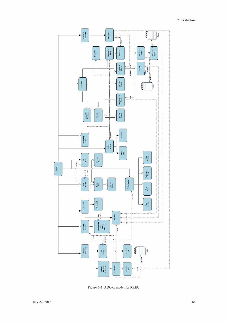
7. Evaluation
July 22, 2016 84
Figure 7-2: ADOxx model for RREG.
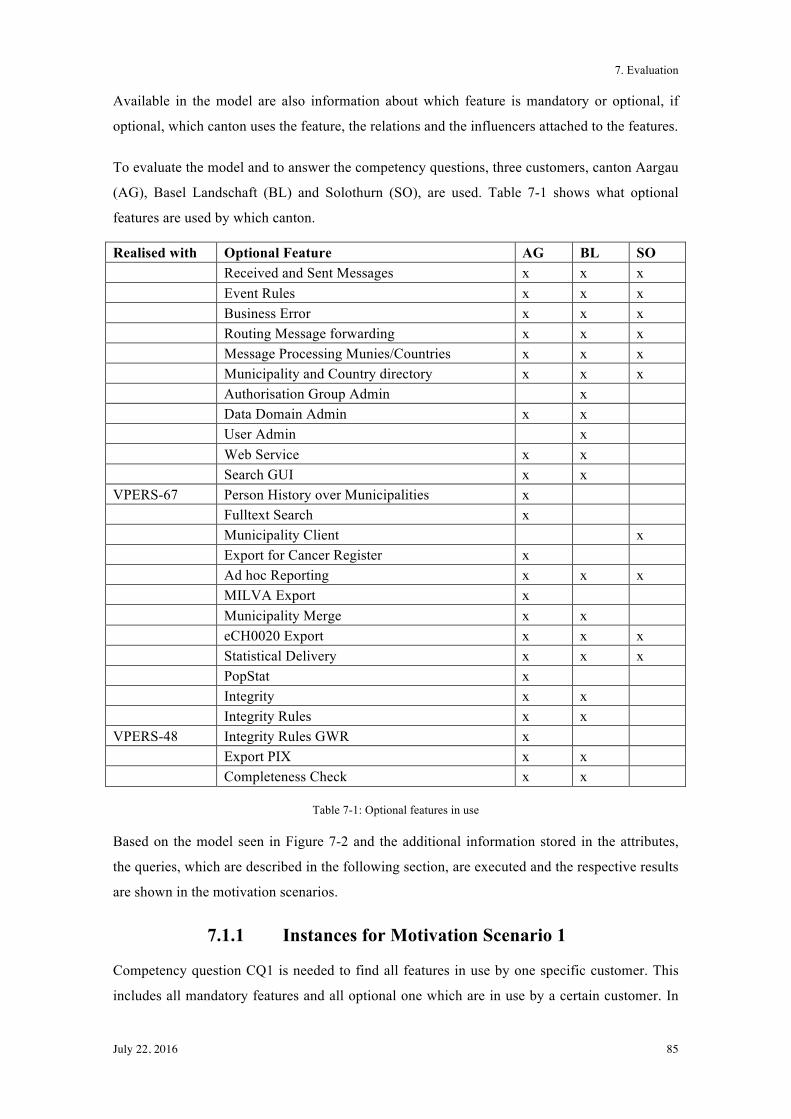
7. Evaluation
July 22, 2016 85
Available in the model are also information about which feature is mandatory or optional, if
optional, which canton uses the feature, the relations and the influencers attached to the features.
To evaluate the model and to answer the competency questions, three customers, canton Aargau
(AG), Basel Landschaft (BL) and Solothurn (SO), are used. Table 7-1 shows what optional
features are used by which canton.
Realised with Optional Feature AG BL SO Received and Sent Messages x x x Event Rules x x x Business Error x x x Routing Message forwarding x x x Message Processing Munies/Countries x x x Municipality and Country directory x x x Authorisation Group Admin x Data Domain Admin x x User Admin x Web Service x x Search GUI x x VPERS-67 Person History over Municipalities x Fulltext Search x Municipality Client x Export for Cancer Register x Ad hoc Reporting x x x MILVA Export x Municipality Merge x x eCH0020 Export x x x Statistical Delivery x x x PopStat x Integrity x x Integrity Rules x x VPERS-48 Integrity Rules GWR x Export PIX x x Completeness Check x x
Table 7-1: Optional features in use
Based on the model seen in Figure 7-2 and the additional information stored in the attributes,
the queries, which are described in the following section, are executed and the respective results
are shown in the motivation scenarios.
7.1.1 Instances for Motivation Scenario 1
Competency question CQ1 is needed to find all features in use by one specific customer. This
includes all mandatory features and all optional one which are in use by a certain customer. In
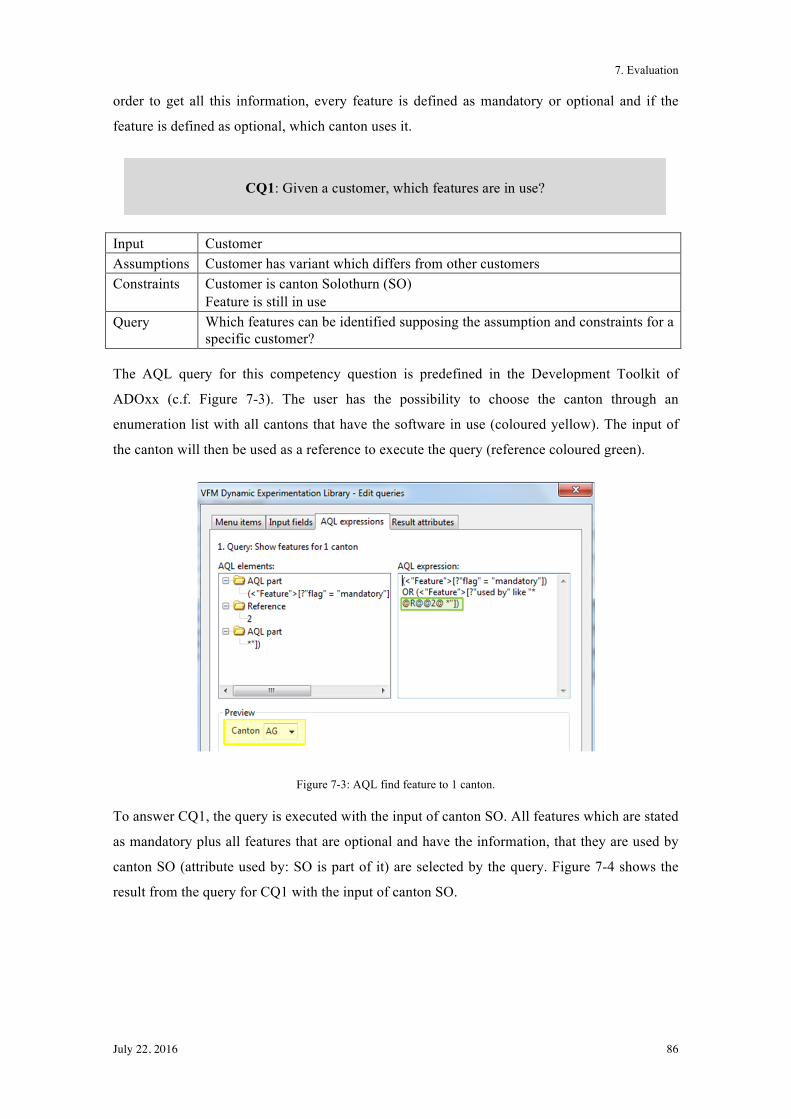
7. Evaluation
July 22, 2016 86
order to get all this information, every feature is defined as mandatory or optional and if the
feature is defined as optional, which canton uses it.
Input Customer Assumptions Customer has variant which differs from other customers Constraints Customer is canton Solothurn (SO)
Feature is still in use Query Which features can be identified supposing the assumption and constraints for a
specific customer?
The AQL query for this competency question is predefined in the Development Toolkit of
ADOxx (c.f. Figure 7-3). The user has the possibility to choose the canton through an
enumeration list with all cantons that have the software in use (coloured yellow). The input of
the canton will then be used as a reference to execute the query (reference coloured green).
Figure 7-3: AQL find feature to 1 canton.
To answer CQ1, the query is executed with the input of canton SO. All features which are stated
as mandatory plus all features that are optional and have the information, that they are used by
canton SO (attribute used by: SO is part of it) are selected by the query. Figure 7-4 shows the
result from the query for CQ1 with the input of canton SO.
CQ1: Given a customer, which features are in use?
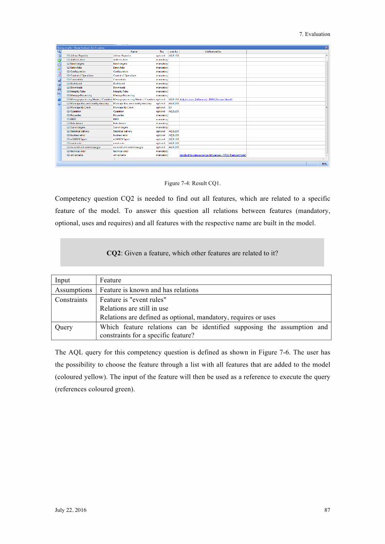
7. Evaluation
July 22, 2016 87
Figure 7-4: Result CQ1.
Competency question CQ2 is needed to find out all features, which are related to a specific
feature of the model. To answer this question all relations between features (mandatory,
optional, uses and requires) and all features with the respective name are built in the model.
Input Feature Assumptions Feature is known and has relations Constraints Feature is "event rules"
Relations are still in use Relations are defined as optional, mandatory, requires or uses
Query Which feature relations can be identified supposing the assumption and constraints for a specific feature?
The AQL query for this competency question is defined as shown in Figure 7-6. The user has
the possibility to choose the feature through a list with all features that are added to the model
(coloured yellow). The input of the feature will then be used as a reference to execute the query
(references coloured green).
CQ2: Given a feature, which other features are related to it?
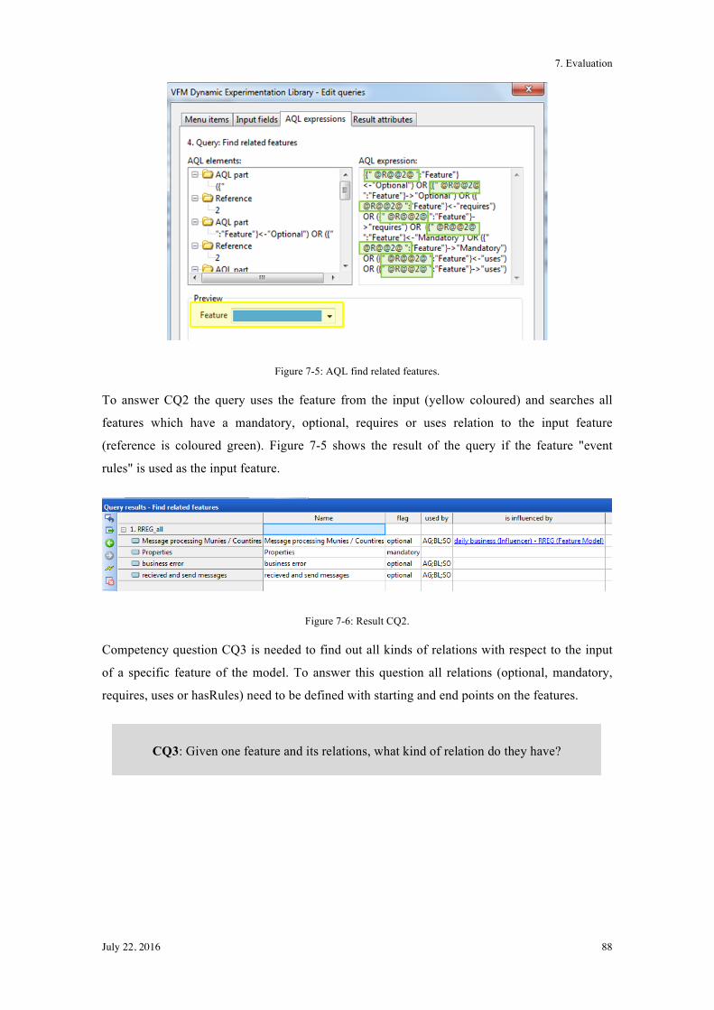
7. Evaluation
July 22, 2016 88
Figure 7-5: AQL find related features.
To answer CQ2 the query uses the feature from the input (yellow coloured) and searches all
features which have a mandatory, optional, requires or uses relation to the input feature
(reference is coloured green). Figure 7-5 shows the result of the query if the feature "event
rules" is used as the input feature.
Figure 7-6: Result CQ2.
Competency question CQ3 is needed to find out all kinds of relations with respect to the input
of a specific feature of the model. To answer this question all relations (optional, mandatory,
requires, uses or hasRules) need to be defined with starting and end points on the features.
CQ3: Given one feature and its relations, what kind of relation do they have?
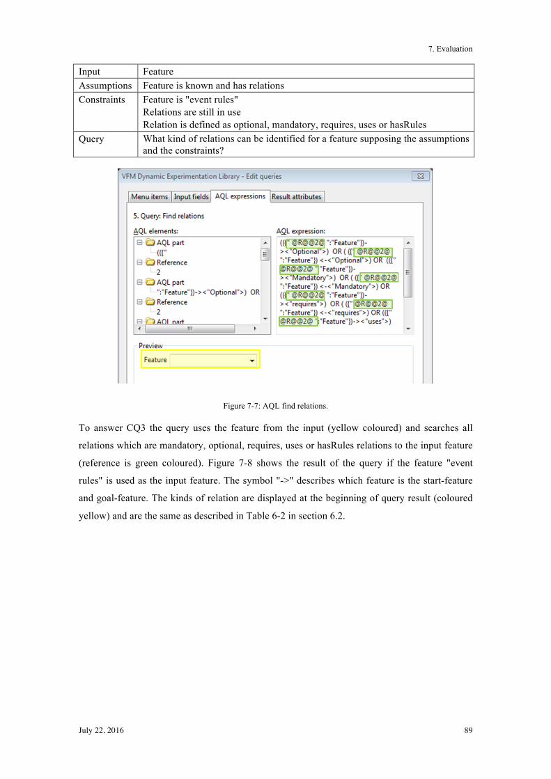
7. Evaluation
July 22, 2016 89
Input Feature Assumptions Feature is known and has relations Constraints Feature is "event rules"
Relations are still in use Relation is defined as optional, mandatory, requires, uses or hasRules
Query What kind of relations can be identified for a feature supposing the assumptions and the constraints?
Figure 7-7: AQL find relations.
To answer CQ3 the query uses the feature from the input (yellow coloured) and searches all
relations which are mandatory, optional, requires, uses or hasRules relations to the input feature
(reference is green coloured). Figure 7-8 shows the result of the query if the feature "event
rules" is used as the input feature. The symbol "->" describes which feature is the start-feature
and goal-feature. The kinds of relation are displayed at the beginning of query result (coloured
yellow) and are the same as described in Table 6-2 in section 6.2.
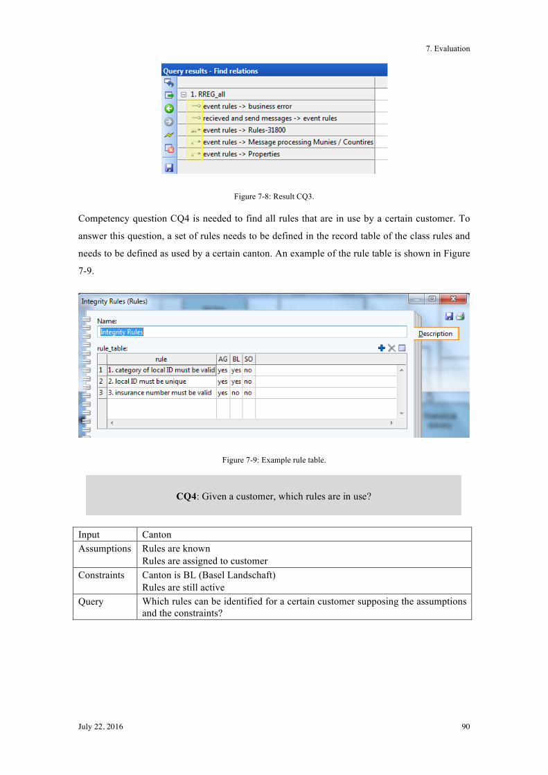
7. Evaluation
July 22, 2016 90
Figure 7-8: Result CQ3.
Competency question CQ4 is needed to find all rules that are in use by a certain customer. To
answer this question, a set of rules needs to be defined in the record table of the class rules and
needs to be defined as used by a certain canton. An example of the rule table is shown in Figure
7-9.
Figure 7-9: Example rule table.
Input Canton Assumptions Rules are known
Rules are assigned to customer Constraints Canton is BL (Basel Landschaft)
Rules are still active Query Which rules can be identified for a certain customer supposing the assumptions
and the constraints?
CQ4: Given a customer, which rules are in use?
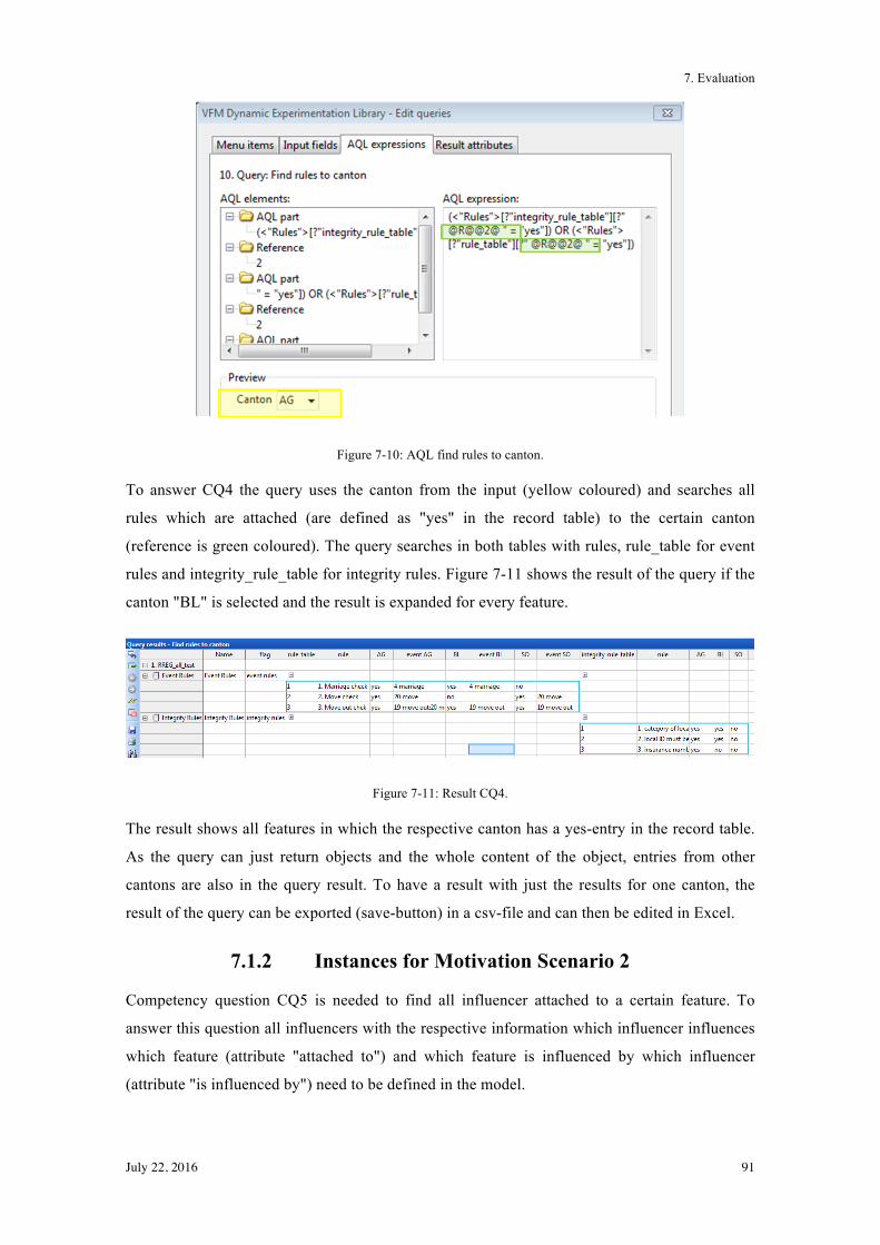
7. Evaluation
July 22, 2016 91
Figure 7-10: AQL find rules to canton.
To answer CQ4 the query uses the canton from the input (yellow coloured) and searches all
rules which are attached (are defined as "yes" in the record table) to the certain canton
(reference is green coloured). The query searches in both tables with rules, rule_table for event
rules and integrity_rule_table for integrity rules. Figure 7-11 shows the result of the query if the
canton "BL" is selected and the result is expanded for every feature.
Figure 7-11: Result CQ4.
The result shows all features in which the respective canton has a yes-entry in the record table.
As the query can just return objects and the whole content of the object, entries from other
cantons are also in the query result. To have a result with just the results for one canton, the
result of the query can be exported (save-button) in a csv-file and can then be edited in Excel.
7.1.2 Instances for Motivation Scenario 2
Competency question CQ5 is needed to find all influencer attached to a certain feature. To
answer this question all influencers with the respective information which influencer influences
which feature (attribute "attached to") and which feature is influenced by which influencer
(attribute "is influenced by") need to be defined in the model.
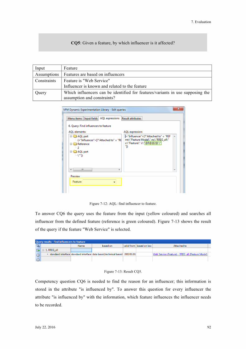
7. Evaluation
July 22, 2016 92
Input Feature Assumptions Features are based on influencers Constraints Feature is "Web Service"
Influencer is known and related to the feature Query Which influencers can be identified for features/variants in use supposing the
assumption and constraints?
Figure 7-12: AQL: find influencer to feature.
To answer CQ6 the query uses the feature from the input (yellow coloured) and searches all
influencer from the defined feature (reference is green coloured). Figure 7-13 shows the result
of the query if the feature "Web Service" is selected.
Figure 7-13: Result CQ5.
Competency question CQ6 is needed to find the reason for an influencer; this information is
stored in the attribute "is influenced by". To answer this question for every influencer the
attribute "is influenced by" with the information, which feature influences the influencer needs
to be recorded.
CQ5: Given a feature, by which influencer is it affected?
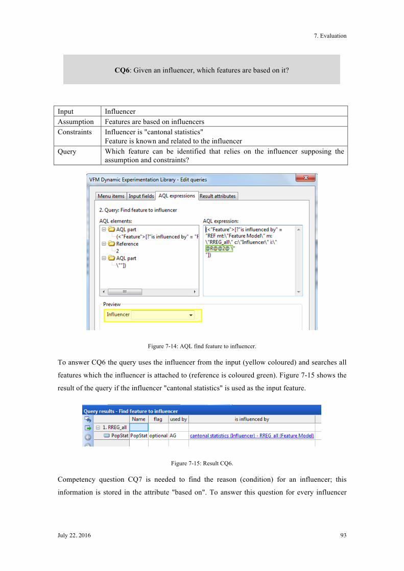
7. Evaluation
July 22, 2016 93
Input Influencer Assumption Features are based on influencers Constraints Influencer is "cantonal statistics"
Feature is known and related to the influencer Query Which feature can be identified that relies on the influencer supposing the
assumption and constraints?
Figure 7-14: AQL find feature to influencer.
To answer CQ6 the query uses the influencer from the input (yellow coloured) and searches all
features which the influencer is attached to (reference is coloured green). Figure 7-15 shows the
result of the query if the influencer "cantonal statistics" is used as the input feature.
Figure 7-15: Result CQ6.
Competency question CQ7 is needed to find the reason (condition) for an influencer; this
information is stored in the attribute "based on". To answer this question for every influencer
CQ6: Given an influencer, which features are based on it?
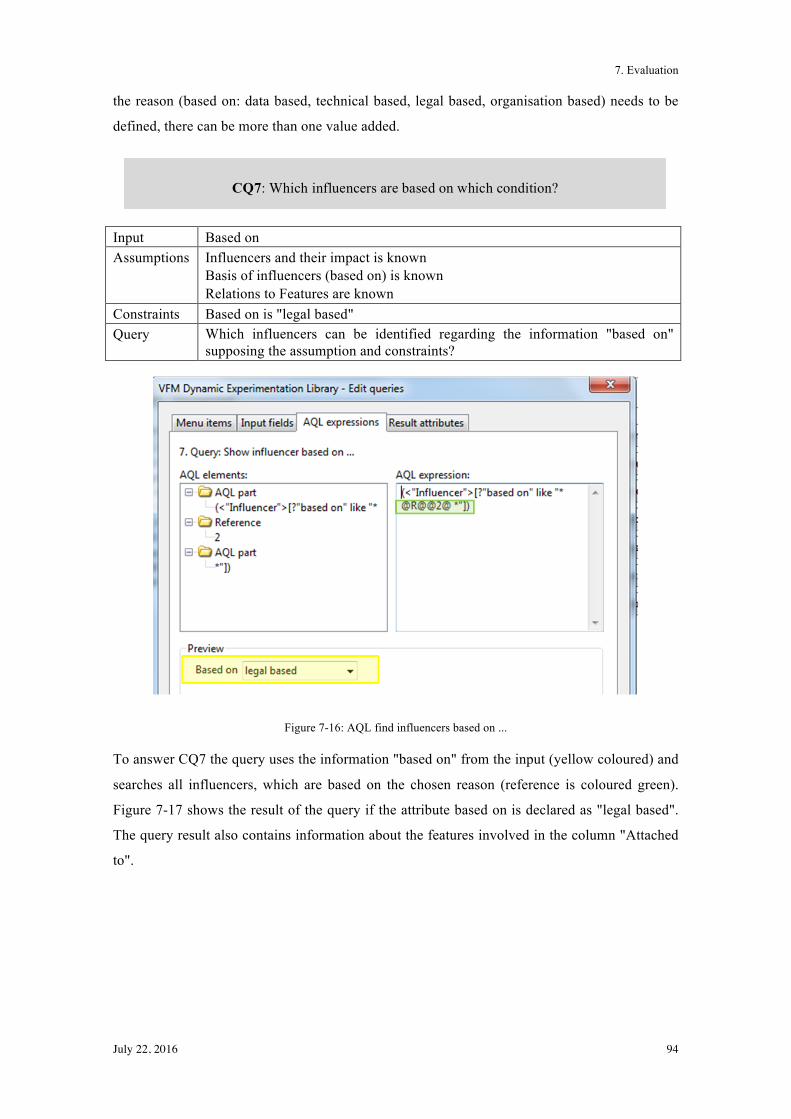
7. Evaluation
July 22, 2016 94
the reason (based on: data based, technical based, legal based, organisation based) needs to be
defined, there can be more than one value added.
Input Based on Assumptions Influencers and their impact is known
Basis of influencers (based on) is known Relations to Features are known
Constraints Based on is "legal based" Query Which influencers can be identified regarding the information "based on"
supposing the assumption and constraints?
Figure 7-16: AQL find influencers based on ...
To answer CQ7 the query uses the information "based on" from the input (yellow coloured) and
searches all influencers, which are based on the chosen reason (reference is coloured green).
Figure 7-17 shows the result of the query if the attribute based on is declared as "legal based".
The query result also contains information about the features involved in the column "Attached
to".
CQ7: Which influencers are based on which condition?
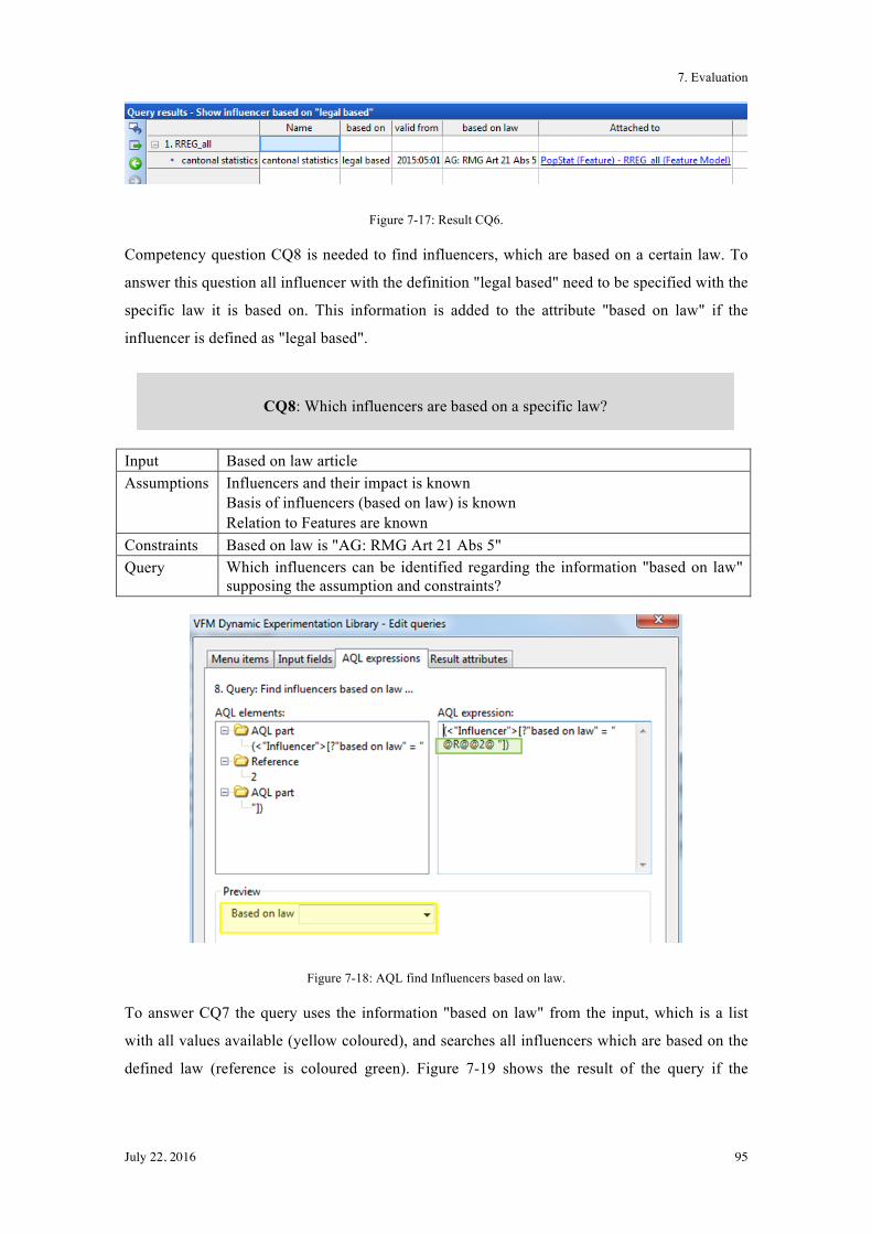
7. Evaluation
July 22, 2016 95
Figure 7-17: Result CQ6.
Competency question CQ8 is needed to find influencers, which are based on a certain law. To
answer this question all influencer with the definition "legal based" need to be specified with the
specific law it is based on. This information is added to the attribute "based on law" if the
influencer is defined as "legal based".
Input Based on law article Assumptions Influencers and their impact is known
Basis of influencers (based on law) is known Relation to Features are known
Constraints Based on law is "AG: RMG Art 21 Abs 5" Query Which influencers can be identified regarding the information "based on law"
supposing the assumption and constraints?
Figure 7-18: AQL find Influencers based on law.
To answer CQ7 the query uses the information "based on law" from the input, which is a list
with all values available (yellow coloured), and searches all influencers which are based on the
defined law (reference is coloured green). Figure 7-19 shows the result of the query if the
CQ8: Which influencers are based on a specific law?
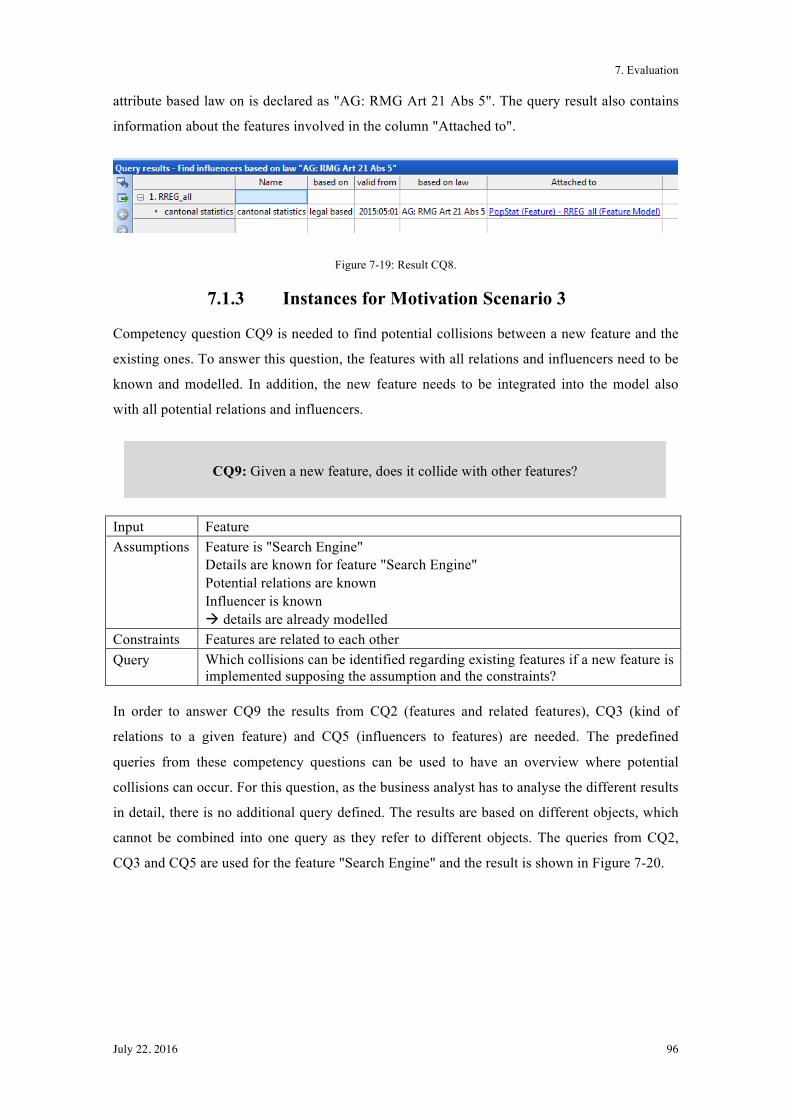
7. Evaluation
July 22, 2016 96
attribute based law on is declared as "AG: RMG Art 21 Abs 5". The query result also contains
information about the features involved in the column "Attached to".
Figure 7-19: Result CQ8.
7.1.3 Instances for Motivation Scenario 3
Competency question CQ9 is needed to find potential collisions between a new feature and the
existing ones. To answer this question, the features with all relations and influencers need to be
known and modelled. In addition, the new feature needs to be integrated into the model also
with all potential relations and influencers.
Input Feature Assumptions Feature is "Search Engine"
Details are known for feature "Search Engine" Potential relations are known Influencer is known ! details are already modelled
Constraints Features are related to each other Query Which collisions can be identified regarding existing features if a new feature is
implemented supposing the assumption and the constraints?
In order to answer CQ9 the results from CQ2 (features and related features), CQ3 (kind of
relations to a given feature) and CQ5 (influencers to features) are needed. The predefined
queries from these competency questions can be used to have an overview where potential
collisions can occur. For this question, as the business analyst has to analyse the different results
in detail, there is no additional query defined. The results are based on different objects, which
cannot be combined into one query as they refer to different objects. The queries from CQ2,
CQ3 and CQ5 are used for the feature "Search Engine" and the result is shown in Figure 7-20.
CQ9: Given a new feature, does it collide with other features?
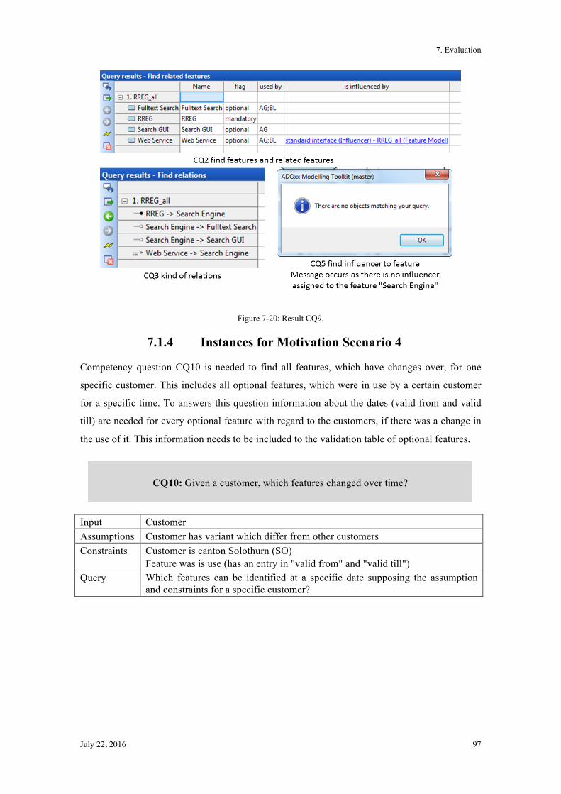
7. Evaluation
July 22, 2016 97
Figure 7-20: Result CQ9.
7.1.4 Instances for Motivation Scenario 4
Competency question CQ10 is needed to find all features, which have changes over, for one
specific customer. This includes all optional features, which were in use by a certain customer
for a specific time. To answers this question information about the dates (valid from and valid
till) are needed for every optional feature with regard to the customers, if there was a change in
the use of it. This information needs to be included to the validation table of optional features.
Input Customer Assumptions Customer has variant which differ from other customers Constraints Customer is canton Solothurn (SO)
Feature was is use (has an entry in "valid from" and "valid till") Query Which features can be identified at a specific date supposing the assumption
and constraints for a specific customer?
CQ10: Given a customer, which features changed over time?
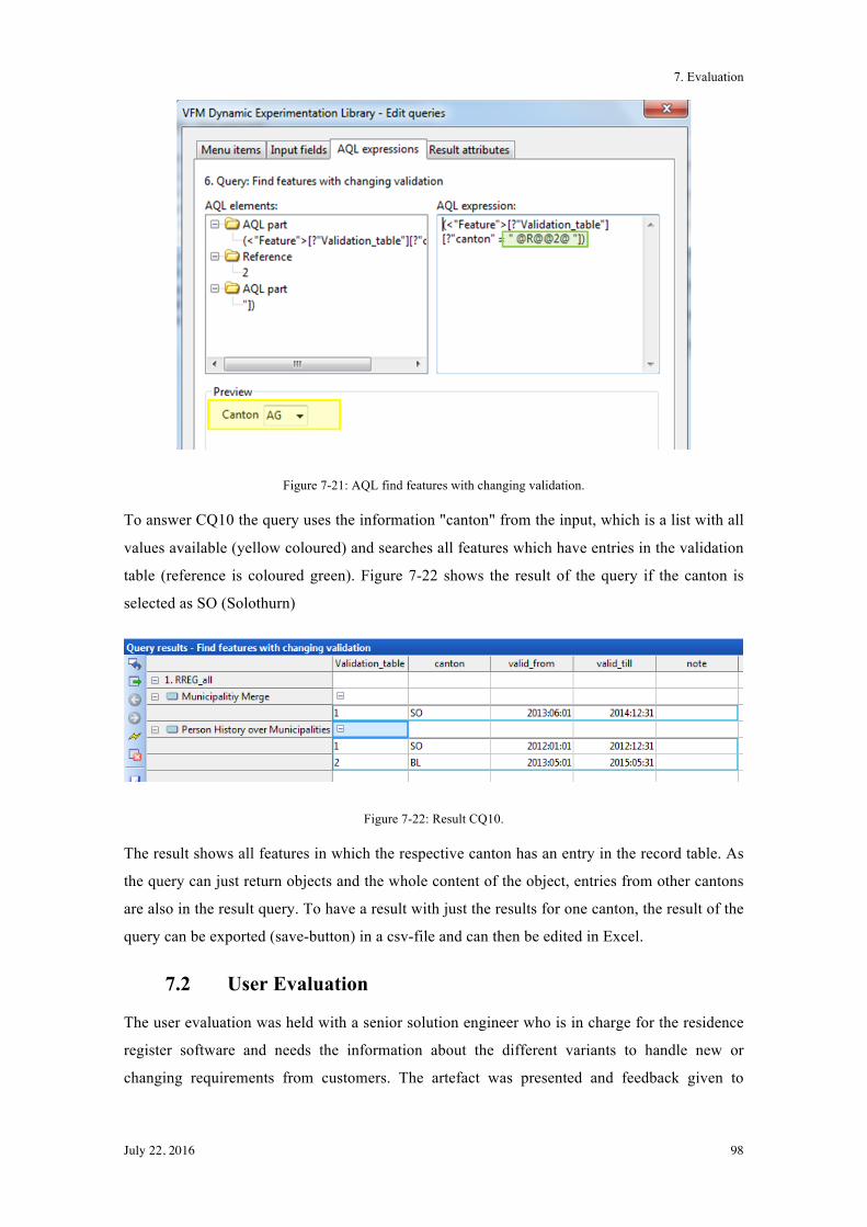
7. Evaluation
July 22, 2016 98
Figure 7-21: AQL find features with changing validation.
To answer CQ10 the query uses the information "canton" from the input, which is a list with all
values available (yellow coloured) and searches all features which have entries in the validation
table (reference is coloured green). Figure 7-22 shows the result of the query if the canton is
selected as SO (Solothurn)
Figure 7-22: Result CQ10.
The result shows all features in which the respective canton has an entry in the record table. As
the query can just return objects and the whole content of the object, entries from other cantons
are also in the result query. To have a result with just the results for one canton, the result of the
query can be exported (save-button) in a csv-file and can then be edited in Excel.
7.2 User Evaluation
The user evaluation was held with a senior solution engineer who is in charge for the residence
register software and needs the information about the different variants to handle new or
changing requirements from customers. The artefact was presented and feedback given to
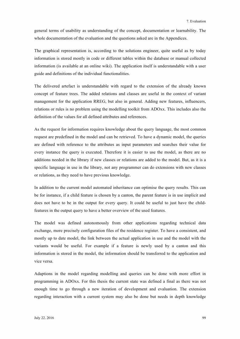
7. Evaluation
July 22, 2016 99
general terms of usability as understanding of the concept, documentation or learnability. The
whole documentation of the evaluation and the questions asked are in the Appendices.
The graphical representation is, according to the solutions engineer, quite useful as by today
information is stored mostly in code or different tables within the database or manual collected
information (is available at an online wiki). The application itself is understandable with a user
guide and definitions of the individual functionalities.
The delivered artefact is understandable with regard to the extension of the already known
concept of feature trees. The added relations and classes are useful in the context of variant
management for the application RREG, but also in general. Adding new features, influencers,
relations or rules is no problem using the modelling toolkit from ADOxx. This includes also the
definition of the values for all defined attributes and references.
As the request for information requires knowledge about the query language, the most common
request are predefined in the model and can be retrieved. To have a dynamic model, the queries
are defined with reference to the attributes as input parameters and searches their value for
every instance the query is executed. Therefore it is easier to use the model, as there are no
additions needed in the library if new classes or relations are added to the model. But, as it is a
specific language in use in the library, not any programmer can do extensions with new classes
or relations, as they need to have previous knowledge.
In addition to the current model automated inheritance can optimise the query results. This can
be for instance, if a child feature is chosen by a canton, the parent feature is in use implicit and
does not have to be in the output for every query. It could be useful to just have the child-
features in the output query to have a better overview of the used features.
The model was defined autonomously from other applications regarding technical data
exchange, more precisely configuration files of the residence register. To have a consistent, and
mostly up to date model, the link between the actual application in use and the model with the
variants would be useful. For example if a feature is newly used by a canton and this
information is stored in the model, the information should be transferred to the application and
vice versa.
Adaptions in the model regarding modelling and queries can be done with more effort in
programming in ADOxx. For this thesis the current state was defined a final as there was not
enough time to go through a new iteration of development and evaluation. The extension
regarding interaction with a current system may also be done but needs in depth knowledge
7. Evaluation
July 22, 2016 100
about the application RREG, how information can be sent from one application to another and
about the programming language of ADOxx. This kind of extension would definitely be too
comprehensive for this thesis and not enough in depth knowledge would be available by today.
7.3 Summary
During the evaluation phase the model is generated and tested against technical and user
requirements. All classes, relations and attributes as modelled for the use cases of RREG with
competency questions in chapter 4.2 are implemented in modelling toolkit from ADOxx. The
RREG software is instanced in the feature tree with the respective attributes for the instances of
the classes and the relations.
The model is also capable to answer all competency questions from the motivation scenarios.
Implementing the model in ADOxx with concrete instances is precondition to check if the
model is consistent and useful in practice.
The user evaluation shows, that the model with its design principles and queries is good
understandable and can be used to handle variants for the current use case. There are still
additions which can be made to the model to make it more flexible and automated. But in
general the evaluation shows that it is a tradable model with the needed information stored.
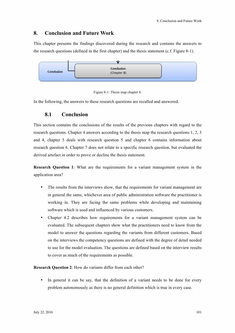
8. Conclusion and Future Work
July 22, 2016 101
8. Conclusion and Future Work
This chapter presents the findings discovered during the research and contains the answers to
the research questions (defined in the first chapter) and the thesis statement (c.f. Figure 8-1).
Figure 8-1: Thesis map chapter 8.
In the following, the answers to these research questions are recalled and answered.
8.1 Conclusion
This section contains the conclusions of the results of the previous chapters with regard to the
research questions. Chapter 4 answers according to the thesis map the research questions 1, 2, 3
and 4, chapter 5 deals with research question 5 and chapter 6 contains information about
research question 6. Chapter 7 does not relate to a specific research question, but evaluated the
derived artefact in order to prove or decline the thesis statement.
Research Question 1: What are the requirements for a variant management system in the
application area?
• The results from the interviews show, that the requirements for variant management are
in general the same, whichever area of public administration software the practitioner is
working in. They are facing the same problems while developing and maintaining
software which is used and influenced by various customers.
• Chapter 4.2 describes how requirements for a variant management system can be
evaluated. The subsequent chapters show what the practitioners need to know from the
model to answer the questions regarding the variants from different customers. Based
on the interviews the competency questions are defined with the degree of detail needed
to use for the model evaluation. The questions are defined based on the interview results
to cover as much of the requirements as possible.
Research Question 2: How do variants differ from each other?
• In general it can be say, that the definition of a variant needs to be done for every
problem autonomously as there is no general definition which is true in every case.
8. Conclusion and Future Work
July 22, 2016 102
• For the current problem of variants in software in a particular context it is mainly
defined what two systems have in common and what differentiates. Common parts can
be seen as core assets which have to be in every variant and different parts are defined
as optional and do not have to be in every system.
• In addition, relations and dependencies within features also need to be taken into
account if a system with all possible elements is created.
Research Question 3: Which variant management methods exist and can be applied to the
problem at hand?
• Methods for variant management are already developed and adapted by different
researchers. For this study the approach of feature trees was used and analysed in more
detail to answer this research question.
• The analysis shows, that the concept of feature trees with the respective representation
of features and relations can be used as a basis for developing the feature model for
variant handling regarding the requirements from software for public administrations. In
addition there are more specifications needed to handle influencers and relations to
represent uses relations.
Research Question 4: What influencers do exist and what is their impact on variant
management?
• The interviews showed that the influencers variants are based on are the same for the
different applications in the area of public administrations. This is fact, as the
applications examined are located in the same area and have customers, which have the
same kind of requirements coming from laws and regulations. The identified influencers
are defined as legal-based, organisational-based, data-based and technical-based.
• The impact from influencers can be huge as they lead to different requirements from
different customers, which cannot be changed. For instance, if a cantonal law changes,
the change has to be made in the application and this may lead to a new feature even if
all other customers will not have to change anything, as the law is strict.
Research Question 5: How can variants and influencers be described?
• In chapters 5.3, 5.4 and 5.5 the step-by-step creation of the conceptual model for
handling variants and influencers is described in detail.
• The suggestion phase shows that variants can be described with the concept of feature
trees, but some adaptions is needed. This includes the addition of influencers to the
8. Conclusion and Future Work
July 22, 2016 103
model with the placement at the boundary of the influenced feature. Also new relations
are defined. One, requires-relation, has the ability to differentiate between features
which have to be in a system if a specific optional feature is chosen. In comparison to
the uses-relation which defines that just information from another feature is needed but
it works also without the related feature.
Research Question 6: How shall a modelling language be defined in order to achieve a simple
representation of the variants?
• Based on the conceptual model, a graphical representation in ADOxx is developed. The
model is defined with three classes (feature, influencer and rules) with the respective
attributes to have all information within the features and five relations (mandatory,
optional, requires, uses and hasRules) to represent the dependencies between features
and rules.
• Features can be added, changed or deleted and relations can be defined by the
practitioners without in depth knowledge about the feature model. Queries can be used
also for adapted models as they are defined dynamically and retrieve the results with the
given input for every execution newly.
• Allowing practitioners to perform adaptions in the model and using the queries to
retrieve information could lead to savings in time
Chapter 7 Evaluation illustrates that the actual results of the evaluation queries matches the
expected results from the competency questions. In addition, practitioner from the software
development department confirmed the model can be useful as it is understandable in a good
way and can be extended if needed.
8.2 Contribution
Contributions of this thesis are described in this section in matters of the thesis statement:
As it is described in the previous chapter, all research questions are answered and the goal of
this thesis is achieved. The research result confirms that a description and graphical model of
variants supports management of software variants and the thesis statement is proven.
A description and graphical modelling of variants, including their requirements and
interdependencies, of software for public administrations in Switzerland support
management of software variants.
8. Conclusion and Future Work
July 22, 2016 104
The technical evaluation and the feedback from interviewees confirm that the need for variant
handling in specific case can be done using the proposed model. It is for example easier to find
all used features for a customer with the model in short time. The model provides individual
queries to answer questions in variant handling and the model can also be changed and enriched
dynamically.
Finally, the concept of feature trees is extended in ADOxx by additional classes (influencers and
rules) and relation (uses) coming from the requirements from Bedag which develops public
administration software.
8.3 Future Work
The research to this study started from a practical issue concerning how variants for software for
public administration can be managed and modelled. The endpoint was the development of
pragmatic integration of the model with regard to the practical solution. During the development
of the model it declared, that for very complex model structures the problem is not completely
solved. It can be complicated to understand and adapt a model with a high number of features
and relations.
The evolution of such a model with changes that can have positive impact on one feature and a
negative one on others is also very important. This also includes standardised communication
between a variant management model within a tool and the software application itself. In
practice a concept on how such communication can be resolved and what is needed to update
both systems automatically should be considered in order to reduce effort in managing variants
manually.
My suggestion for future research is to focus on the specification of handling feature trees with
a high number of features and relations. As already stated, the evolution (manually or
automated) is also an approach which should be considered for future work.
Bibliography
July 22, 2016 105
Bibliography
Acher, M., Collet, P., Lahire, P., & France, R. (2010). Comparing approaches to implement
feature model composition. Lecture Notes in Computer Science (Including Subseries
Lecture Notes in Artificial Intelligence and Lecture Notes in Bioinformatics), 6138 LNCS,
3–19. doi:10.1007/978-3-642-13595-8_3
ADOxx Development Language: AQL. (n.d.). Retrieved June 13, 2016, from
https://www.adoxx.org/live/adoxx-query-language-aql
ADOxx Documentation: AttrRep. (n.d.). Retrieved June 13, 2016, from
https://www.adoxx.org/live/attrrep
ADOxx Documentation: Class Attribute and Attribute Types. (n.d.). Retrieved from
https://www.adoxx.org/live/class-attribute-and-attribute-types
ADOxx Documentation: GraphRep. (n.d.). Retrieved June 13, 2016, from
https://www.adoxx.org/live/graphrep).
ADOxx Documentation: Query Core. (n.d.). Retrieved June 9, 2016, from
https://www.adoxx.org/live/query-core
ADOxx Documentation: Relations in ADOxx. (n.d.). Retrieved June 13, 2016, from
https://www.adoxx.org/live/relations
Al-Badareen, A. B., Selamat, M. H., Jabar, M. A., Din, J., & Turaev, S. (2011). The Impact of
Software Quality on Maintenance Process, 5(2), 183–190.
AL-Badareen, A., Selamat, M., & Jabar, M. (2011). Reusable Software Component Life Cycle.
International Journal of Computers, 5(2), 191–199. Retrieved from
http://www.naun.org/multimedia/NAUN/computers/19-863.pdf
Apel, S., & Batory, D. (2013). Feature-Oriented Software Product Lines.
Bachmann, F., & Bass, L. (2001). Managing variability in software architectures. ACM
SIGSOFT Software Engineering Notes, 26, 126–132. doi:10.1145/379377.375274
Bachmann, F., & Clements, P. C. (2005). Variability in software product lines. Technical
Report CMU/SEI-2005-TR012. Software Engineering Institute, Pittsburgh, USA,
(September), 46.
Bibliography
July 22, 2016 106
Batory, D. (2005). Feature Models, Grammars, and Propositional Formulas. Software Product
Lines, 2005, 7–20. doi:10.1007/11554844_3
Baur, S. (2014). Consolidate and Extend the Representation of Business Process Variability
Using a new Feature Model Notation and its Procedure.
Becker, J., Algermissen, L., Delfmann, P., & Niehaves, B. (2003). Konstruktion
konfigurierbarer Referenzmodelle für die öffentliche Verwaltung Management von
Varianten in Verwaltungsreferenzmodellen Konfigurative Referenzmodellierung als
Grundlage des Variantenmanagements, 249–253.
Becker, J., Algermissen, L., Delfmann, P., & Niehaves, B. (2005). Referenzmodellierung in
öffentlichen Verwaltungen am Beispiel des prozessorientierten Reorganisationsprojekts
Regio@KomM. Wirtschaftsinformatik 2005!: eEconomy, eGovernment, eSociety, 729–
745. doi:10.1007/3-7908-1624-8_38
Bedag Informatik AG. (2016a). Die Personenregisterlösung für die öffentliche Verwaltung.
Retrieved March 21, 2016, from http://www.bedag.ch/dienstleistungen/software-
entwicklung/fachloesungen/register/ , access: 21.03.2016
Bedag Informatik AG. (2016b). Die zukunftssichere Lösung für elektronische Grundbuchdaten.
Bedag Informatik AG. (2016c). Individuell erweiterbare Standardlösung für die Sozialarbeit.
Retrieved March 21, 2016, from http://www.bedag.ch/dienstleistungen/software-
entwicklung/fachloesungen/sozialwesen/
Beuche, D., & Dalgarno, M. (2007). Software Product Line Engineering with Feature Models.
Structure, 15(78), 1 – 7. Retrieved from http://www.pure-
systems.com/fileadmin/downloads/pure-variants/tutorials/SPLWithFeatureModelling.pdf
Beuche, D., & Dalgarno, M. (2008). Product Line Engineering: Versions, Variants and all the
rest – Basic definitions. Retrieved November 27, 2015, from
https://productlines.wordpress.com/2008/07/04/versions-variants-and-all-the-rest-basic-
definitions/
Beuche, D., Papajewski, H., & Schröder-Preikschat, W. (2004). Variability management with
feature models. Science of Computer Programming, 53(3), 333–352.
doi:10.1016/j.scico.2003.04.005
Böckle, G., Knauber, P., Pohl, K., & Schmid, K. (2004). Softwareproduktlinien Methoden,
Bibliography
July 22, 2016 107
Einführung und Praxis (1. Auflage). Schmid, Klaus.
Böllert, K. (2001). Objektorientierte Entwicklung ovn Software-Produktlinien zur
Serienfertigung von Software-Systemen.
Bosch, J. (2000). Adopting Software Product Lines: Approaches, Artefacts and Organization,
15213–15213.
Buchholz, M., & Souren, R. (2008). Ilmenauer Schriften zur Betriebswirtschaftslehre
Variantenvielfalt: Definitorische Überlegungen zu einem zentralen Begriff des
Variantenmanagements. Retrieved from www.tu-ilmenau.de/is-ww
Bundesamt für Statistik. (2016). Sedex. Retrieved from
http://www.bfs.admin.ch/bfs/portal/de/index/news/00/00/02.html,
Bundesversammlung der Schweizerischen Eidgenossenschaft. Bundesgesetz über die
Harmonisierung der Einwohnerregister und anderer amtlicher Personenregister (2006).
Switzerland.
Ciaghi, A., Villafiorita, A., & Mattioli, A. (2009). VLPM: A tool to support BPR in public
administration. Proceedings of the 3rd International Conference on Digital Society, ICDS
2009, 289–293. doi:10.1109/ICDS.2009.46
Fazal-E-Amin, Mahmood, A. K., & Oxley, A. (2010). A proposed reusability attribute model
for aspect oriented software product line components. Proceedings 2010 International
Symposium on Information Technology - System Development and Application and
Knowledge Society, ITSim’10, 3, 1138–1141. doi:10.1109/ITSIM.2010.5561503
Fill, H.-G., Redmond, T., & Karagiannis, D. (2012). FDMM: A Formalism for Describing
ADOxx Meta Models and Models. ICEIS 2012 - 14th International Conference on
Enterprise Information Systems, 3, 133–144. Retrieved from
http://eprints.cs.univie.ac.at/3472/
Grosse-Rhode, M., Kleinod, E., & Mann, S. (2007). Entscheidungsgrundlagen für die
Entwicklung von Softwareproduktlinien. Retrieved from
http://en.scientificcommons.org/25677976
Gruninger, M., & Fox, M. S. (1994). The Role of Competency Questions in Enterprise
Engineering. IFIP WG5 - 7 Workshop on Benchmarking - Theory and Practice, 1–17.
doi:10.1007/978-0-387-34847-6_3
Bibliography
July 22, 2016 108
Halmans, G., & Pohl, K. (2001). Considering Product Family Assets when Defining Customer
Requirements. Erfurt: Fraunhofer IESE.
Helms, R., Giovacchini, E., Teigland, R., & Kohler, T. (2010). A Design Research Approach to
Developing User Innovation Workshops in Second Life, 3(1), 3–36.
Hevner, A., & Chatterjee, S. (2010). Design Research in Information Systems, 22, 9–23.
doi:10.1007/978-1-4419-5653-8
Hevner, A., March, S., Park, J., & Ram, S. (2004). Design Science in Information Systems
Research. MIS Quarterly, 28(1), 75–105. doi:10.2307/25148625
Hinkelmann, K., Thönssen, B., & Probst, F. (2005). Referenzmodellierung fçr E-Government-
Services. Wirtschaftsinformatik, 47, 356–366.
Hofstee, E. (2006). Constructing a good dissertation. Retrieved from www.exactica.co.za
Ilyas, M., Abbas, M., & Saleem, K. (2013). A Metric Based Approach to Extract , Store and
Deploy Software Reusable Components Effectively, 10(4), 257–264.
Introduction to ADOxx. (n.d.). Retrieved June 9, 2016, from https://www.adoxx.org/live/adoxx-
documentation
Kang, K. C., Cohen, S. G., Hess, J. A., Novak, W. E., & Peterson, A. S. (1990). Feature-
Oriented Domain Analysis ({FODA}): A Feasibility Study, (CMU/SEI-90-TR-21).
Karagiannis, D., & Kühn, H. (2002). Metamodelling Platforms. Bauknecht, K.; Min Tjoa, A.;
Quirchmayer, G. (Eds.): Proceedings of the Third International Conference EC-Web
2002, 4082(September 2002), 222–231. doi:10.1007/11823865
Kersten, W. (2002). Vielfaltsmanagement Integrative Lösungsansätze zur Optimierung und
Beherrschung der Produkt- und Teilevielfalt (1. Auflage). München: TCW Transfer-
Centrum für Produktions-Logistik und Technologie-Management.
Kesper, H. (2012). Gestaltung von Produktvariantenspektren mittels matrixbasierter Methoden.
Klarin, K. ., & Mladenović, S. . (2012). The method of knowledge distribution and use in public
administration. MIPRO 2012 - 35th International Convention on Information and
Communication Technology, Electronics and Microelectronics - Proceedings, 1672–1677.
Retrieved from http://www.scopus.com/inward/record.url?eid=2-s2.0-
Bibliography
July 22, 2016 109
84865102001&partnerID=40&md5=e39145e6fb4c2f96c48aaf22aa02e50a
Kubica, S. (2007). Variantenmanagement modellbasierter Funktionssoftware mit Software-
Produktlinien. Friedrich-Alexander-Universität Erlangen Nürnberg.
Kuechler, B., & Vaishnavi, V. (2008). Theory Development in Design Science Research:
Anatomy of a Research Project. Retrieved from http://www.palgrave-
journals.com/ejis/journal/v17/n5/abs/ejis200840a.html
Kunz, A. (2005). Planung Variantenreicher Produkte.
Lee, K., Kang, K. C., & Lee, J. (2002). Concepts and Guidelines of Feature Modeling for
Product Line Software Engineering. Lecture Notes in Computer Science, (January).
doi:10.1007/b98465
Manz, C., Stupperich, M., & Reichert, M. (2013). Towards Integrated Variant Management in
Global Software Engineering: An Experience Report. 2013 IEEE 8th International
Conference on Global Software Engineering, 168–172. doi:10.1109/ICGSE.2013.29
Mccall, J. a., Richards, P. K., & Walters, G. F. (1977). Factors in software quality: Concept and
Definitions of Software Quality, I(November), 188.
Nuseibeh, B., & Easterbrook, S. (2000). Requirements Engineering": A Roadmap. In
Proceedings of the Conference on the Future of Software Engineering.
Omg. (2010). Business Motivation Model. Omg, (November), /. doi:formal/2008-08-02
Pohl, K., Böckle, G., & van der Linden, F. (2005). Software Product Line Engineering:
Foundations, Principles and Techniques. Springer-Verlag Berlin Heidelberg.
doi:10.1007/3-540-28901-1
Pohl, K., & Metzger, A. (2008). Variabilitätsmanagement in Software-Produktlinien.
Conference: Software Engineering 2008. Fachtagung Des GI-Fachbereichs
Softwaretechnik, 18.-22.2.2008 in München, 28–41. Retrieved from
http://www.researchgate.net/publication/221232462_Variabilittsmanagement_in_Software
-Produktlinien
PTC Integrity Business Unit Locations. (2012). Managing Product Variants in a Software
Product Line with PTC Integrity. Retrieved from PTC.com/product/integrity
Bibliography
July 22, 2016 110
ROI Management Consulting AG. (2015). Variantenmanagement. Retrieved November 13,
2015, from http://www.logistiklexikon.de/lexikon/liste/V/
Rosenmüller, M., Siegmund, N., Thüm, T., & Saake, G. (2011). Multi-dimensional variability
modeling. 5th Workshop on Variability Modeling of Software-Intensive Systems, 11–20.
doi:10.1145/1944892.1944894
Saunders, M., Lewis, P., & Thornhill, A. (2009). Research Methods for Business Students.
Research methods for business students.
Schobbens, P. Y., Heymans, P., Trigaux, J. C., & Bontemps, Y. (2006). Feature Diagrams: A
survey and a formal semantics. Proceedings of the IEEE International Conference on
Requirements Engineering, 136–145. doi:10.1109/RE.2006.23
Shaker, P., Atlee, J. M., & Wang, S. (2012). A feature-oriented requirements modelling
language. 2012 20th IEEE International Requirements Engineering Conference, RE 2012 -
Proceedings, 151–160. doi:10.1109/RE.2012.6345799
Software Engineering Institute Carnegie Melon University. (2012). A Framework for Software
Product Line Practice, Version 5.0. Retrieved October 23, 2015, from
http://www.sei.cmu.edu/productlines/frame_report/what.is.a.PL.htm
Takeda, H., Veerkamp, P., Tomiyama, T., & Yoshikawam, H. (1990). Modeling design
processes. AI Magazine, 11, 4 (Winter 1990), 11(4), 37–48.
Thiel, S., & Hein, A. (2002). Modeling and Using Product Line Variability in Automotive
Systems. IEEE Softw., 19(August), 66–72.
doi:http://dx.doi.org/10.1109/MS.2002.1020289
Thüm, T., Kästner, C., Benduhn, F., Meinicke, J., Saake, G., & Leich, T. (2014). FeatureIDE:
An extensible framework for feature-oriented software development. Science of Computer
Programming, 79, 70–85. doi:10.1016/j.scico.2012.06.002
Thüm, T., Kästner, C., Erdweg, S., & Siegmund, N. (2011). Abstract features in feature
modeling. Proceedings - 15th International Software Product Line Conference, SPLC
2011, 191–200. doi:10.1109/SPLC.2011.53
Trochim, W. M. K. (2006). Deduction & Induction. Retrieved October 30, 2015, from
http://www.socialresearchmethods.net/kb/dedind.php
Bibliography
July 22, 2016 111
Uschold, M., & Gruninger, M. (1996). Ontologies": Principles , Methods and Applications.
Knowledge Engineering Review, 11(2), 69.
Vaishnavi, V., & Kuechler, B. (2004). Design Science Research in Information Systems.
Retrieved November 13, 2015, from http://desrist.org/design-research-in-information-
systems/
van den Linden, F., Schmid, K., & Rommes, E. (2007). Software Product Lines in Action, The
Best Industrial Practice in Product Line Engineering. Springer-Verlag.
Voigt, K.-I. (2013). Varianten. Retrieved November 13, 2015, from
http://wirtschaftslexikon.gabler.de/Definition/varianten.html
Yu, E. S. K. (1997). Towards modelling and reasoning support for early-phase requirements
engineering. Proceedings of ISRE ’97: 3rd IEEE International Symposium on
Requirements Engineering, 226–235. doi:10.1109/ISRE.1997.566873
Zave, P. (1995). Problems of specifying software system behavior alternative strategies for
satisfying requirements into specific properties or behavior 1 . 3 . Generating strategies for
allocating requirements 2 . 5 . Checking that the specified system will satisfy the a, 214–
216.
Zhang, W., Mei, H., & Zhao, H. (2005). A feature-oriented approach to modeling requirements
dependencies. Proceedings of the 13th IEEE International Conference on Requirements
Engineering, 273–282. doi:10.1109/RE.2005.6
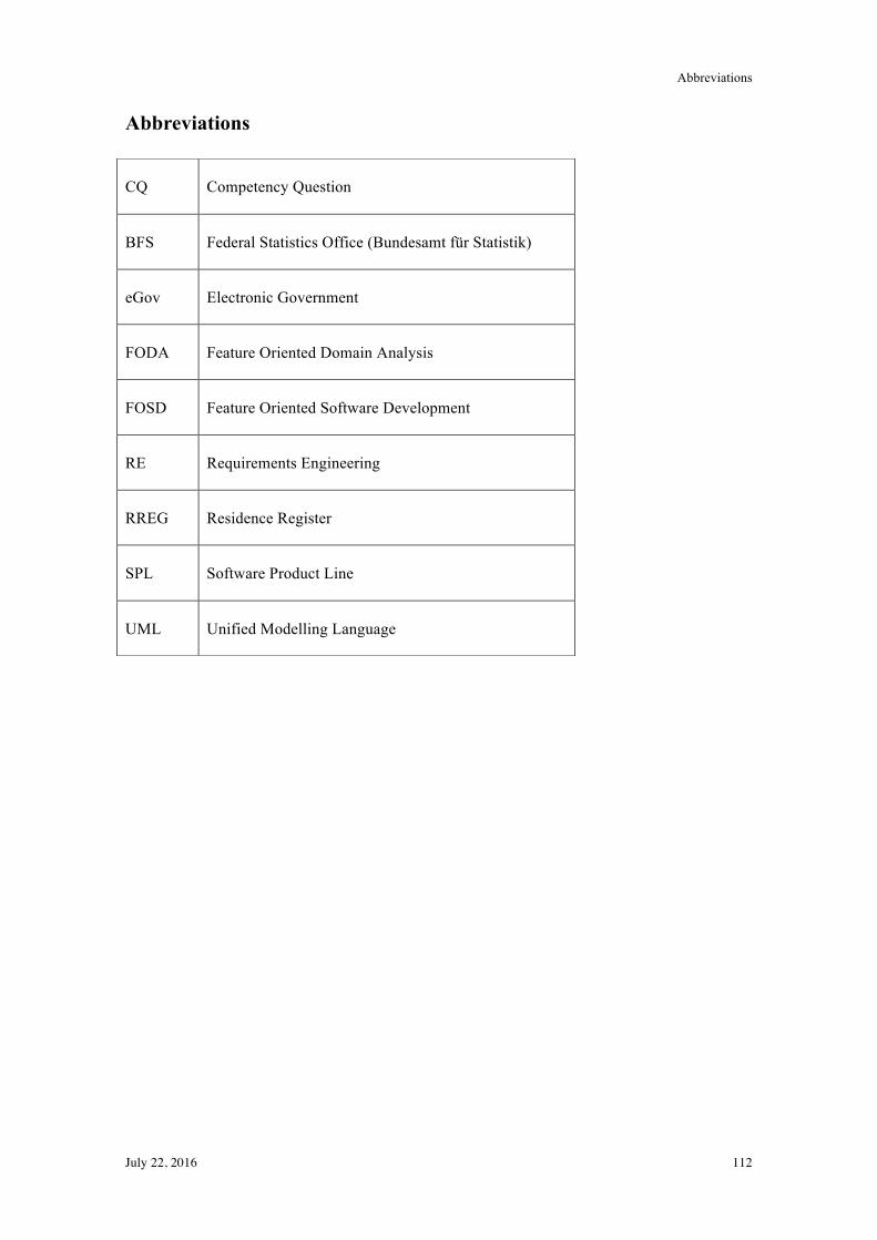
Abbreviations
July 22, 2016 112
Abbreviations
CQ Competency Question
BFS Federal Statistics Office (Bundesamt für Statistik)
eGov Electronic Government
FODA Feature Oriented Domain Analysis
FOSD Feature Oriented Software Development
RE Requirements Engineering
RREG Residence Register
SPL Software Product Line
UML Unified Modelling Language
List of Figures / Tables
July 22, 2016 113
List of Figures / Tables
Figures
Figure 1-1: Chapter map. ............................................................................................................... 6!
Figure 2-1: RESAD framework (Ilyas et al., 2013). ................................................................... 13!
Figure 2-2: Software maintenance process (Al-Badareen et al., 2011). ...................................... 14!
Figure 2-3: Reference process for software product line engineering (Böckle et al., 2004). ...... 16!
Figure 2-4: The relation of different types of variability (van den Linden et al., 2007, p.9). ..... 17!
Figure 2-5: FODA (OFT): monitor engine system (Schobbens et al., 2006). ............................. 20!
Figure 2-6: Explicit representation of variation points in use case diagrams (Böckle et al., 2004,
p.72). ............................................................................................................................................ 24!
Figure 3-1: Research onion (Saunders, Lewis, & Thornhill, 2009, p.108). ................................ 26!
Figure 3-2: Inductive reasoning (Trochim, 2006). ...................................................................... 28!
Figure 3-3: Design science research cycles (Hevner & Chatterjee, 2010, p.16). ........................ 29!
Figure 3-4: 5-steps design cycle (Vaishnavi & Kuechler, 2004). ............................................... 30!
Figure 3-5: Research choices (Saunders et al., 2009, p.152). ...................................................... 31!
Figure 3-6: Types of secondary data (Saunders et al., 2009, p.259). .......................................... 33!
Figure 3-7: Research design. ....................................................................................................... 34!
Figure 4-1: Thesis map chapter 4. ............................................................................................... 38!
Figure 4-2: Procedure for a formal approach to ontology design and evaluation (Uschold &
Gruninger, 1996, p.28). ............................................................................................................... 42!
Figure 4-3: Layers of competency questions (Uschold & Gruninger, 1996, p.30). .................... 43!
Figure 4-4: Causes and influencers. ............................................................................................ 50!
Figure 4-5: Changing merge of feature models (Acher et al., 2010). .......................................... 54!
Figures
July 22, 2016 114
Figure 4-6: Structure and notation of feature models (Beuche & Dalgarno, 2007). ................... 55!
Figure 5-1: Thesis map chapter 5. ............................................................................................... 58!
Figure 5-2 Data flow Geres ......................................................................................................... 59!
Figure 5-3: Components RREG. ................................................................................................. 60!
Figure 5-4: Feature tree RREG. ................................................................................................... 62!
Figure 5-5: Feature tree RREG message processing. .................................................................. 63!
Figure 5-6: Feature tree RREG authorisation. ............................................................................. 64!
Figure 5-7: Feature tree RREG search engine. ............................................................................ 66!
Figure 5-8: Feature tree RREG configuration. ............................................................................ 66!
Figure 5-9: Feature tree RREG operations. ................................................................................. 67!
Figure 5-10: Feature tree RREG with requirements and usage. .................................................. 70!
Figure 5-11: Conceptual model RREG with influencers. ........................................................... 72!
Figure 6-1: Thesis map chapter 6. ............................................................................................... 74!
Figure 6-2: Generic modelling method framework. .................................................................... 75!
Figure 6-3: Class diagram of ADOxx Meta2Model. .................................................................... 76!
Figure 6-4: Feature tree part of RREG. ....................................................................................... 78!
Figure 6-5: Notebook view of class feature chapter description. ................................................ 79!
Figure 6-6: Notebook view of class feature chapter validation table. ......................................... 79!
Figure 6-7: Notebook view of class influencer. .......................................................................... 80!
Figure 6-8: Notebook view of class rules chapter description. ................................................... 81!
Figure 7-1: Thesis map chapter 7. ............................................................................................... 83!
Figure 7-2: ADOxx model for RREG. ........................................................................................ 84!
Figures
July 22, 2016 115
Figure 7-3: AQL find feature to 1 canton. ................................................................................... 86!
Figure 7-4: Result CQ1. .............................................................................................................. 87!
Figure 7-5: AQL find related features. ........................................................................................ 88!
Figure 7-6: Result CQ2. .............................................................................................................. 88!
Figure 7-7: AQL find relations. ................................................................................................... 89!
Figure 7-8: Result CQ3. .............................................................................................................. 90!
Figure 7-9: Example rule table. ................................................................................................... 90!
Figure 7-10: AQL find rules to canton. ....................................................................................... 91!
Figure 7-11: Result CQ4. ............................................................................................................ 91!
Figure 7-12: AQL: find influencer to feature. ............................................................................. 92!
Figure 7-13: Result CQ5. ............................................................................................................ 92!
Figure 7-14: AQL find feature to influencer. .............................................................................. 93!
Figure 7-15: Result CQ6. ............................................................................................................ 93!
Figure 7-16: AQL find influencers based on ... ........................................................................... 94!
Figure 7-17: Result CQ6. ............................................................................................................ 95!
Figure 7-18: AQL find Influencers based on law. ....................................................................... 95!
Figure 7-19: Result CQ8. ............................................................................................................ 96!
Figure 7-20: Result CQ9. ............................................................................................................ 97!
Figure 7-21: AQL find features with changing validation. ......................................................... 98!
Figure 7-22: Result CQ10. .......................................................................................................... 98!
Figure 8-1: Thesis map chapter 8. ............................................................................................. 101!
Figure 0-1: example of a feature tree with a changing requirement. ......................................... 117!
Tables
July 22, 2016 116
Figure 0-2: ADOxx overview. .................................................................................................. 119!
Figure 0-3: Example of a part of RREG as feature tree. ........................................................... 119!
Figure 0-4: Notebook view of class feature chapter description. .............................................. 120!
Figure 0-5: Notebook view of class feature chapter validation table. ....................................... 121!
Figure 0-6: Notebook view of class influencer. ........................................................................ 121!
Figure 0-7: Notebook view of class rules chapter description. ................................................. 122!
Tables
Table 3-1: Research strategies (Saunders et al., 2009, p.141) ..................................................... 29!
Table 3-2: Design science research guidelines (Hevner & Chatterjee, 2010) ............................. 31!
Table 4-1: Variability concepts ................................................................................................... 52!
Table 4-2: Existing concepts ....................................................................................................... 53!
Table 5-1: Objects feature tree .................................................................................................... 61!
Table 5-2: Relations within feature tree. ..................................................................................... 68!
Table 5-3: Rules within feature tree. ........................................................................................... 69!
Table 5-4: Influencers. ................................................................................................................. 71!
Table 6-1: Classes of the graphical model ................................................................................... 81!
Table 6-2: Relations of the graphical model ............................................................................... 82!
Table 7-1: Optional features in use .............................................................................................. 85!
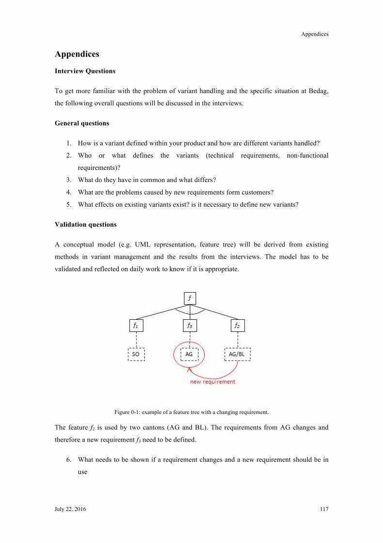
Appendices
July 22, 2016 117
Appendices
Interview Questions
To get more familiar with the problem of variant handling and the specific situation at Bedag,
the following overall questions will be discussed in the interviews.
General questions
1. How is a variant defined within your product and how are different variants handled?
2. Who or what defines the variants (technical requirements, non-functional
requirements)?
3. What do they have in common and what differs?
4. What are the problems caused by new requirements form customers?
5. What effects on existing variants exist? is it necessary to define new variants?
Validation questions
A conceptual model (e.g. UML representation, feature tree) will be derived from existing
methods in variant management and the results from the interviews. The model has to be
validated and reflected on daily work to know if it is appropriate.
Figure 0-1: example of a feature tree with a changing requirement.
The feature f2 is used by two cantons (AG and BL). The requirements from AG changes and
therefore a new requirement f3 need to be defined.
6. What needs to be shown if a requirement changes and a new requirement should be in
use
Appendices
July 22, 2016 118
7. What are the requirements a model has to fulfil in order to handle variants as well as
changing and new requirements?
8. What are the requirements and criteria to check if a model for variant management for
public administration software is appropriate?
9. ?
Evaluation Feature Tree RREG in ADOxx
General Information
The goal is to evaluate the usability including understandability, documentation and learnability
of the feature tree of RREG modelled in ADOxx. The document is divided into the introduction
and general usage of the software ADOxx with the feature tree for RREG in particular and the
handling of the defined query to answer the predefined competency questions.
Introduction into ADOxx
Figure 0-2 show the GUI of ADOxx with additional information. New elements can be added to
a model with drag and drop of the needed element of the feature tree. Attributes can be added to
the elements can be added via DoubleClick on the element to be edited. The notebook view
appears and information can be added (details follow in later parts)
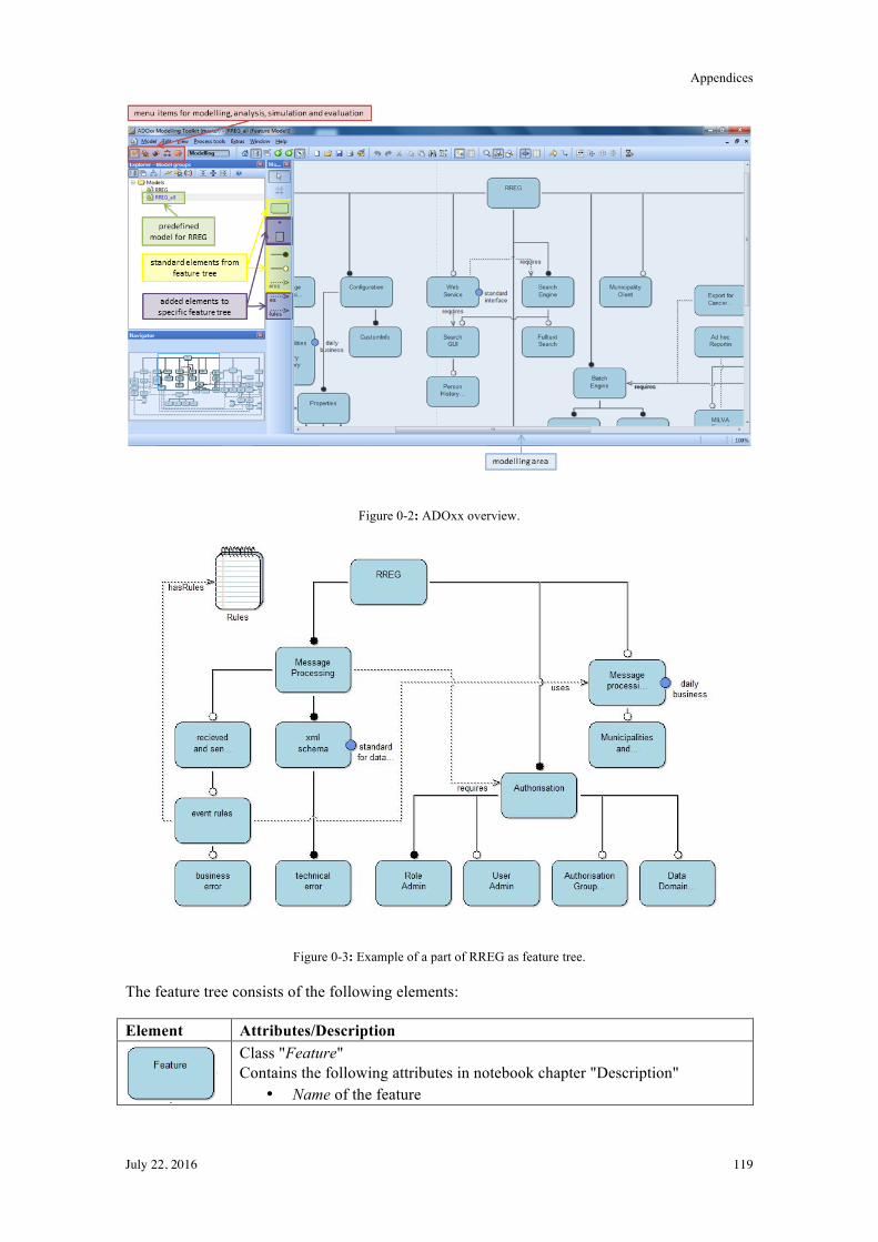
Appendices
July 22, 2016 119
Figure 0-2: ADOxx overview.
Figure 0-3: Example of a part of RREG as feature tree.
The feature tree consists of the following elements:
Element Attributes/Description
Class "Feature" Contains the following attributes in notebook chapter "Description"
• Name of the feature
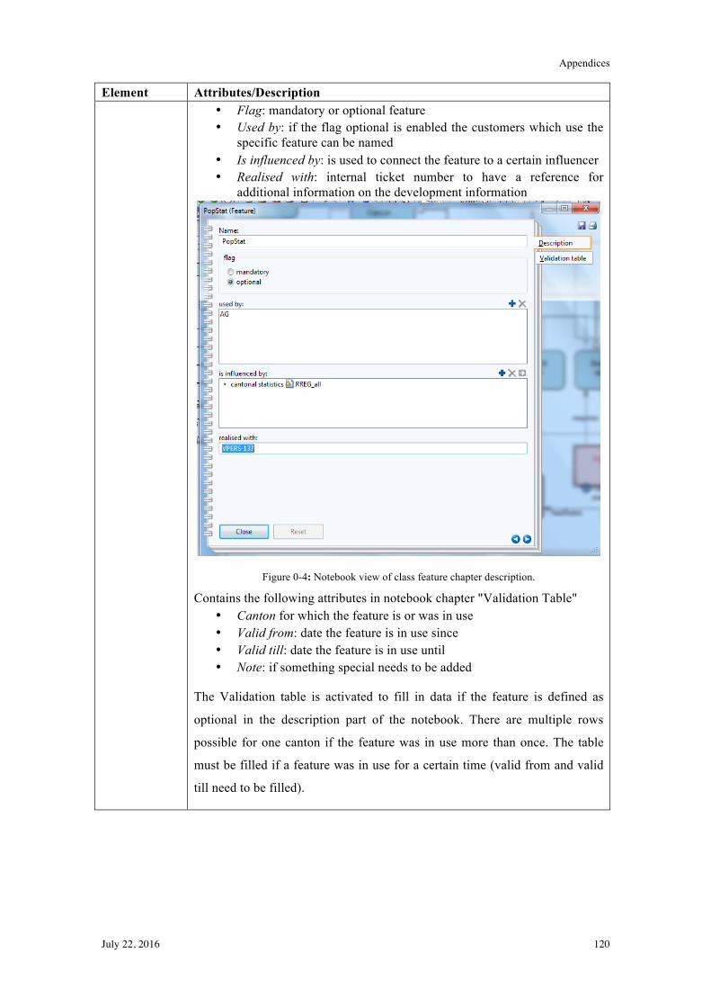
Appendices
July 22, 2016 120
Element Attributes/Description • Flag: mandatory or optional feature • Used by: if the flag optional is enabled the customers which use the
specific feature can be named • Is influenced by: is used to connect the feature to a certain influencer • Realised with: internal ticket number to have a reference for
additional information on the development information
Figure 0-4: Notebook view of class feature chapter description.
Contains the following attributes in notebook chapter "Validation Table" • Canton for which the feature is or was in use • Valid from: date the feature is in use since • Valid till: date the feature is in use until • Note: if something special needs to be added
The Validation table is activated to fill in data if the feature is defined as
optional in the description part of the notebook. There are multiple rows
possible for one canton if the feature was in use more than once. The table
must be filled if a feature was in use for a certain time (valid from and valid
till need to be filled).
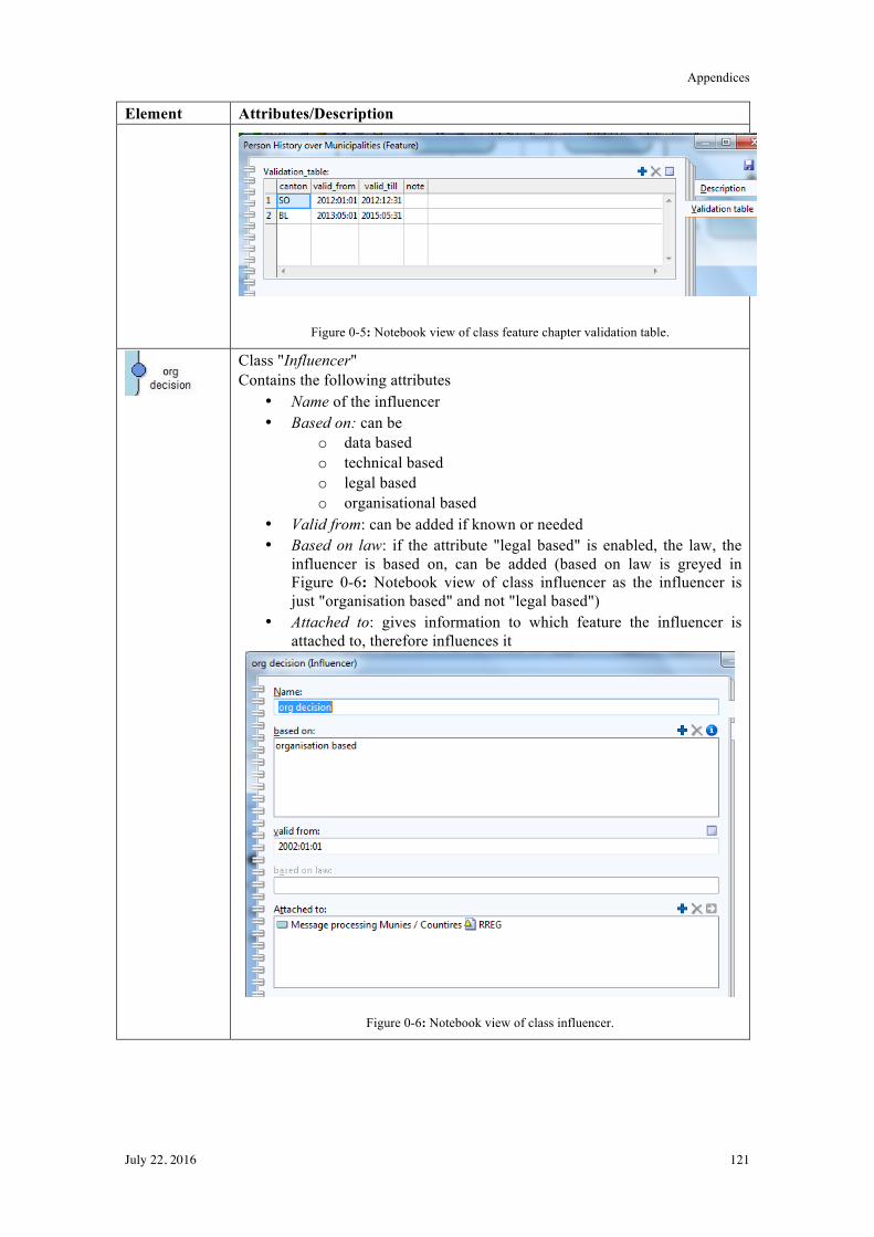
Appendices
July 22, 2016 121
Element Attributes/Description
Figure 0-5: Notebook view of class feature chapter validation table.
Class "Influencer" Contains the following attributes
• Name of the influencer • Based on: can be
o data based o technical based o legal based o organisational based
• Valid from: can be added if known or needed • Based on law: if the attribute "legal based" is enabled, the law, the
influencer is based on, can be added (based on law is greyed in Figure 0-6: Notebook view of class influencer as the influencer is just "organisation based" and not "legal based")
• Attached to: gives information to which feature the influencer is attached to, therefore influences it
Figure 0-6: Notebook view of class influencer.
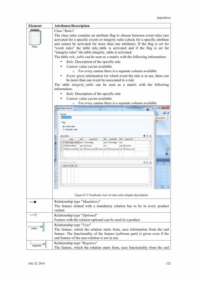
Appendices
July 22, 2016 122
Element Attributes/Description
Class "Rules" The class rules contains an attribute flag to choose between event rules (are activated for a specific event) or integrity rules (check for a specific attribute and cannot be activated for more than one attribute). If the flag is set for "event rules" the table rule_table is activated and if the flag is set for "integrity rules" the table integrity_table is activated. The table rule_table can be seen as a matrix with the following information:
• Rule: Description of the specific rule • Canton: value yes/no available
o For every canton there is a separate column available • Event: gives information for which event the rule is in use, there can
be more than one event be associated to a rule The table integrity_table can be seen as a matrix with the following information:
• Rule: Description of the specific rule • Canton: value yes/no available
o For every canton there is a separate column available
Figure 0-7: Notebook view of class rules chapter description.
Relationship type "Mandatory" The feature related with a mandatory relation has to be in every product variant
Relationship type "Optional" Feature with the relation optional can be used in a product
Relationship type "Uses" The feature, which the relation starts from, uses information from the end feature. The functionality of the feature (software part) is given even if the end feature of the uses relation is not in use.
Relationship type "Requires" The feature, which the relation starts from, uses functionality from the end
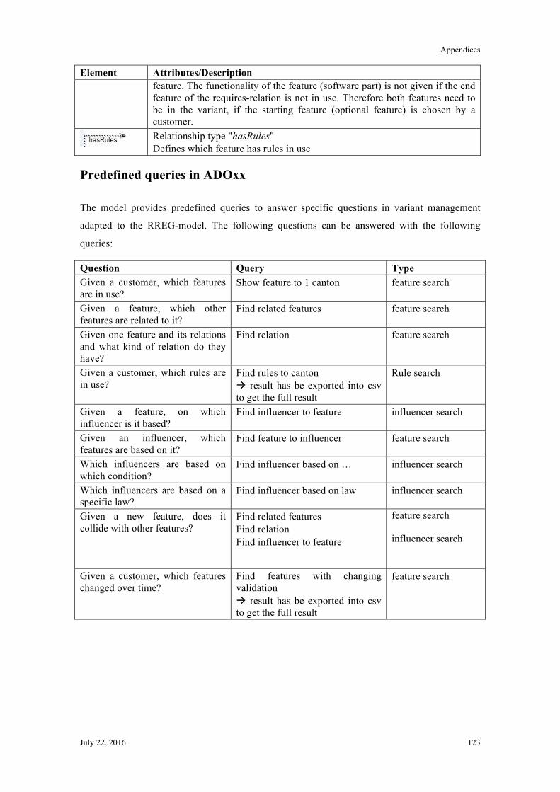
Appendices
July 22, 2016 123
Element Attributes/Description feature. The functionality of the feature (software part) is not given if the end feature of the requires-relation is not in use. Therefore both features need to be in the variant, if the starting feature (optional feature) is chosen by a customer.
Relationship type "hasRules" Defines which feature has rules in use
Predefined queries in ADOxx
The model provides predefined queries to answer specific questions in variant management
adapted to the RREG-model. The following questions can be answered with the following
queries:
Question Query Type Given a customer, which features are in use?
Show feature to 1 canton feature search
Given a feature, which other features are related to it?
Find related features feature search
Given one feature and its relations and what kind of relation do they have?
Find relation feature search
Given a customer, which rules are in use?
Find rules to canton ! result has be exported into csv to get the full result
Rule search
Given a feature, on which influencer is it based?
Find influencer to feature influencer search
Given an influencer, which features are based on it?
Find feature to influencer feature search
Which influencers are based on which condition?
Find influencer based on … influencer search
Which influencers are based on a specific law?
Find influencer based on law influencer search
Given a new feature, does it collide with other features?
Find related features Find relation Find influencer to feature
feature search
influencer search
Given a customer, which features changed over time?
Find features with changing validation ! result has be exported into csv to get the full result
feature search
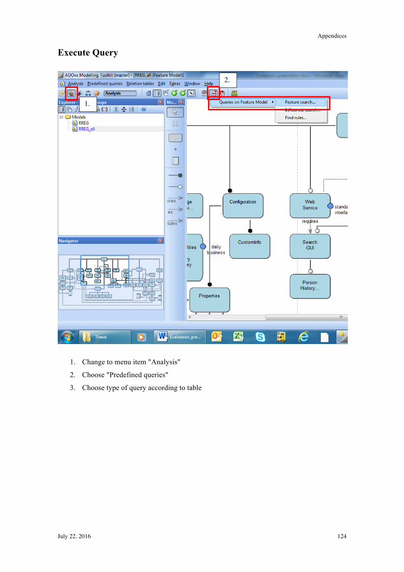
Appendices
July 22, 2016 124
Execute Query
1. Change to menu item "Analysis"
2. Choose "Predefined queries"
3. Choose type of query according to table
1.
2.
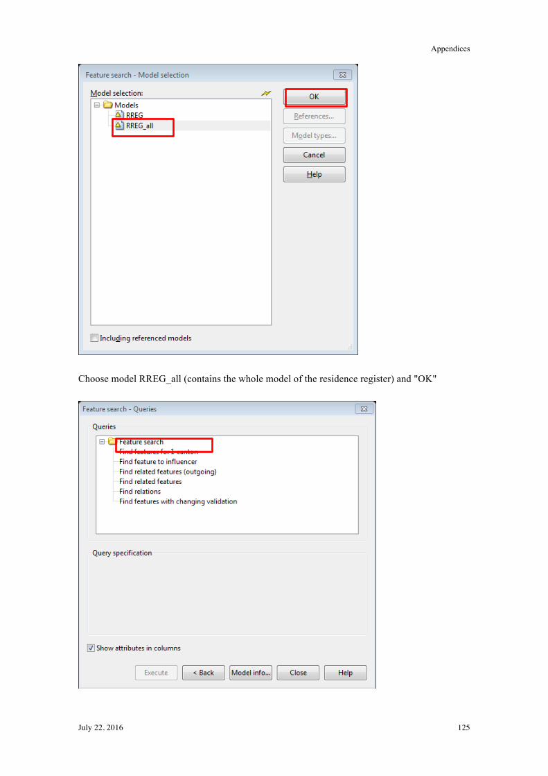
Appendices
July 22, 2016 125
Choose model RREG_all (contains the whole model of the residence register) and "OK"
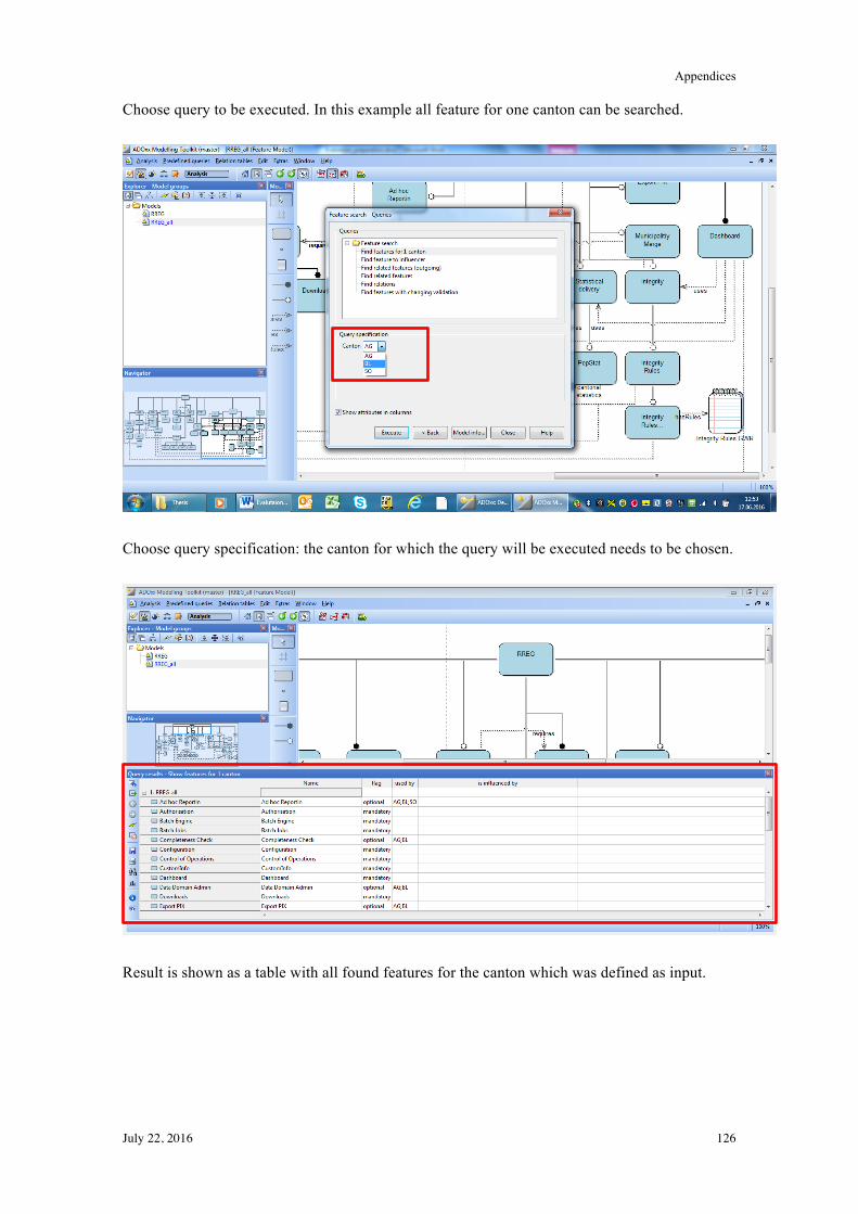
Appendices
July 22, 2016 126
Choose query to be executed. In this example all feature for one canton can be searched.
Choose query specification: the canton for which the query will be executed needs to be chosen.
Result is shown as a table with all found features for the canton which was defined as input.
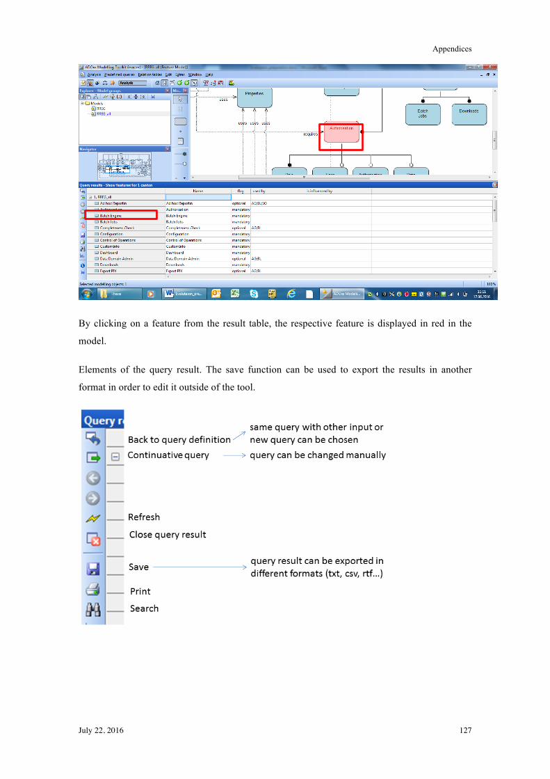
Appendices
July 22, 2016 127
By clicking on a feature from the result table, the respective feature is displayed in red in the
model.
Elements of the query result. The save function can be used to export the results in another
format in order to edit it outside of the tool.
Appendices
July 22, 2016 128
Evaluation Criteria
Usability
• Is the model understandable with the documentation (graphical representation)?
• Can the tool be handled (adding new elements, changes)?
• Is all needed information available to handle variants (classes, relations, attributes)?
Queries
• Is the handling, which query is used for what, understandable?
• Are the results meaningful?


![AMVG: Adaptive Malware Variant Generation Framework ......perturbation applications similarly as in [6]. C. Genetic algorithm for malware variant generations GA has been used widely](https://static.fdocuments.us/doc/165x107/600c68fbf68b6b152e285354/amvg-adaptive-malware-variant-generation-framework-perturbation-applications.jpg)