Variable Stiffness Beam - Worcester Polytechnic Institute · Variable Stiffness Beam ... Chapter 4:...
99
Variable Stiffness Beam A Major Qualifying Project Report: Submitted to the Faculty of the WORCESTER POLYTECHNIC INSITITUTE In partial fulfillment of the requirements for the Degree of Bachelors of Science By ____________ _____________ Jared Drake Gerard Libby ____________ Brian Silvia Date: April 28 th 2011 Approved: ______________________________________ Christopher A. Brown, Major Advisor
Transcript of Variable Stiffness Beam - Worcester Polytechnic Institute · Variable Stiffness Beam ... Chapter 4:...

Variable Stiffness Beam
A Major Qualifying Project Report:
Submitted to the Faculty of the
WORCESTER POLYTECHNIC INSITITUTE
In partial fulfillment of the requirements for the
Degree of Bachelors of Science
By
____________ _____________
Jared Drake Gerard Libby
____________
Brian Silvia
Date: April 28th 2011
Approved:
______________________________________
Christopher A. Brown, Major Advisor

2
Contents Chapter 1: Introduction ................................................................................................................................ 9
1.1 Objective ............................................................................................................................................. 9
1.2 Rationale ............................................................................................................................................. 9
1.3 State of the Art .................................................................................................................................. 10
1.4 Approach ........................................................................................................................................... 12
1.5 Method ............................................................................................................................................. 13
1.6 Design Introduction .......................................................................................................................... 14
Chapter 2: Testing ....................................................................................................................................... 16
2.1 Production of the Composite Shaft................................................................................................... 16
2.1.1 Initial Shaft ................................................................................................................................. 16
2.1.2 Second Shaft .............................................................................................................................. 17
2.2 Testing Frame .................................................................................................................................... 17
2.2.1 Initial Frame ............................................................................................................................... 17
2.2.2 Revised Frame ............................................................................................................................ 19
2.3 Testing Process .................................................................................................................................. 20
2.3.1 Initial Process ............................................................................................................................. 20
2.3.2 Revised Process .......................................................................................................................... 21
2.4 Testing Theory ................................................................................................................................... 21
2.5 Testing assessment ........................................................................................................................... 23
Chapter 3: Shear Friction Design ................................................................................................................ 24
3.1 Shear Friction - Concept and Theory of Operation ........................................................................... 24
3.2 Shear Friction - Decomposition ......................................................................................................... 26
3.2.1 Level One Decomposition .......................................................................................................... 26
3.2.2 Level 2 Decompositions ............................................................................................................. 27
3.2.3 Level 3 Decompositions ............................................................................................................. 34
3.3 Shear Friction - Physical Integration ................................................................................................. 38
3.3.1 Finite Element Analysis .............................................................................................................. 38
3.3.2 Tolerancing ................................................................................................................................. 41
3.3.3 Diagrams .................................................................................................................................... 43

3
3.4 Shear Friction - Prototype Manufacturing ........................................................................................ 46
3.5 Shear Friction - Results ..................................................................................................................... 48
3.6 Shear Friction - Discussion ................................................................................................................ 56
4.7 Shear Locking Conclusion .................................................................................................................. 58
Chapter 4: Shear Locking Design ................................................................................................................. 59
4.1 Shear Locking – Concept and Theory of Operation .......................................................................... 59
4.2 Shear Locking – Design Decomposition ............................................................................................ 60
4.2.1 Level One Decomposition .......................................................................................................... 60
4.2.2 Level 2 Decomposition ............................................................................................................... 61
4.2.3 Level 3 Decomposition ............................................................................................................... 62
4.2.4 Level 4 Decomposition ............................................................................................................... 64
4.3 Shear Locking – Physical Integration................................................................................................. 65
4.3.1 Assembly .................................................................................................................................... 65
4.3.2 Tolerancing ................................................................................................................................. 67
4.4 Shear Locking – Prototype Manufacturing ....................................................................................... 70
4.4.1 Component Models ................................................................................................................... 71
4.5 Shear Locking – Results ..................................................................................................................... 74
4.6 Shear Locking – Discussion ............................................................................................................... 77
4.7 Shear Locking – Conclusions ............................................................................................................. 78
Chapter 5: Variable Volume Design ............................................................................................................ 79
5.1 Variable Volume - Concept and Theory of Operation ...................................................................... 79
5.2 Variable Volume - Decomposition .................................................................................................... 80
5.2.1 Level One Decomposition .......................................................................................................... 80
5.2.2 Level Two Decomposition .......................................................................................................... 81
5.2.3 Level Three Decomposition ....................................................................................................... 83
5.3 Variable Volume - Physical Integration ............................................................................................. 83
5.3.1 Tolerancing ................................................................................................................................. 83
5.3.2 Diagram ...................................................................................................................................... 84
5.4 Variable Volume - Results ................................................................................................................. 85
5.5 Variable Volume - Discussion ............................................................................................................ 88

4
5.6 Variable Volume – Conclusion .......................................................................................................... 88
Chapter 6: Discussion .................................................................................................................................. 90
Chapter 7: Conclusions ............................................................................................................................... 92
Works Cited ................................................................................................................................................. 93
Appendix ..................................................................................................................................................... 94
Aluminum Bar Data and Graph ............................................................................................................... 94
Aluminum Bar Data – Revised Testing Frame and Procedure ............................................................ 94
Aluminum Bar Graph – Revised Testing Frame and Procedure .......................................................... 95
Variable Volume Data and Graphs .......................................................................................................... 96
Variable Volume Data – Initial Testing Frame and Procedure ............................................................ 96
Variable Volume Data – Revised Testing Frame and Procedure ........................................................ 97
Variable Volume Graph – Revised Testing Frame and Procedure ...................................................... 98

5
Table of Figures
Figure 1: Cable Operated Variable Stiffness Shaft Patent .......................................................................... 11
Figure 2: Adjustable Block Hockey Stick Patent .......................................................................................... 12
Figure 3: Hockey Stick Coordinate System .................................................................................................. 15
Figure 4: Initial Test Schematic ................................................................................................................... 18
Figure 5: Initial Test Photograph ................................................................................................................. 18
Figure 6: Revised Testing Schematic ........................................................................................................... 19
Figure 7: Revised Testing Photograph ........................................................................................................ 20
Figure 8: Cantilevered Beam Configuration ................................................................................................ 22
Figure 9: CAD model of Shear Friction Assembly ........................................................................................ 25
Figure 10: Two Piece Bearing Block ............................................................................................................ 31
Figure 11: McMaster-Carr Spring Plunger .................................................................................................. 33
Figure 12: Shear Friction Handle ................................................................................................................. 33
Figure 13: Shear Friction Helix .................................................................................................................... 36
Figure 14: Shear Friction FEA of Rigid Beam ............................................................................................... 39
Figure 15: Shear Friction FEA of Flexible Beam .......................................................................................... 40
Figure 16: Shear Friction FR 1 Diagram ....................................................................................................... 43
Figure 17: Shear Friction FR 2 Diagram ....................................................................................................... 44
Figure 18: Shear Friction FR 3 Diagram ....................................................................................................... 45
Figure 19: Shear Friction FR 4 Diagram ....................................................................................................... 46
Figure 20: Shear Friction Final Prototype Picture ....................................................................................... 48
Figure 21: Shear Friction Initial Test Schematic .......................................................................................... 49
Figure 22: Shear Friction Revised Test Schematic ...................................................................................... 51
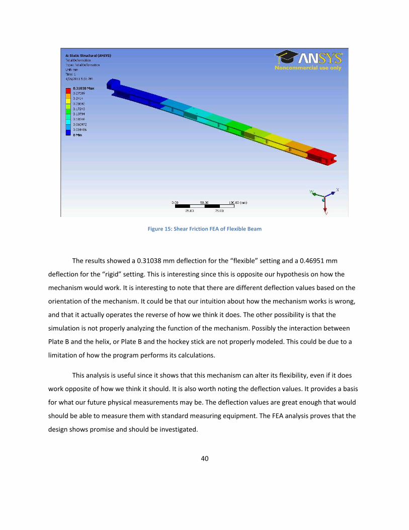
Figure 23: Shear Friction 20g Test Result Graph ......................................................................................... 54
Figure 24: Shear Friction 40g Test Result Graph ......................................................................................... 54
Figure 25: Shear Friction 60g Test Result Graph ......................................................................................... 55
Figure 26: Shear Locking CAD Assembly ..................................................................................................... 60
Figure 27: Shear Locking FR 1.1 Diagram .................................................................................................... 65
Figure 28: Shear Locking FR 1.2 Diagram .................................................................................................... 65
Figure 29: Shear Locking FR 1.2.6 Diagram ................................................................................................. 66
Figure 30: Shear Locking FR 1.2.7 Diagram ................................................................................................. 66
Figure 31: Shear Locking FR 3 Diagram ....................................................................................................... 67
Figure 32: Shear Locking Rotating Shaft CAD Model .................................................................................. 71

6
Figure 33: Shear Locking Fixed Profile CAD Model ..................................................................................... 72
Figure 34: Shear Locking Bushing Block Model .......................................................................................... 72
Figure 35: Shear Locking Bushing Guide Rail Model ................................................................................... 73
Figure 36: Shear Locking Bushing and Shaft Assembly ............................................................................... 73
Figure 37: Shear Locking Testing Schematic ............................................................................................... 74
Figure 38: Variable Volume FR Diagram ..................................................................................................... 84
Figure 39: Variable Volume Deflections with 20g Graph ............................................................................ 87
Figure 40: Aluminum Bar Data Graph ......................................................................................................... 95
Figure 41: Variable Volume Revised Testing 20g Deflection Graph ........................................................... 99

7
Table of Tables
Table 1: Shear Friction Level 1 FRs and DPs ................................................................................................ 26
Table 2: Shear Friction Level 2 for FR and DP 1 .......................................................................................... 27
Table 3: Shear Friction Level 2 of FR and DP 2 ............................................................................................ 29
Table 4:Shear Friction Level 2 of FR and DP 3 ............................................................................................. 30
Table 5: Shear Friction Level 2 of FR and DP 4 ............................................................................................ 32
Table 6: Shear Friction Level 3 of FR and DP 1.2 ......................................................................................... 34
Table 7: Shear Friction Level 3 of FR and DP 2.1 ......................................................................................... 35
Table 8: Shear Friction Level 3 of FR and DP 2.2 ......................................................................................... 36
Table 9: Shear Friction Level 3 of FR and DP 2.3 ......................................................................................... 37
Table 10: Shear Friction Bearing Thickness Tolerances .............................................................................. 41
Table 11: Shear Friction Bearing Groove Tolerance ................................................................................... 42
Table 12: Shear Friction Test 1 Results ....................................................................................................... 50
Table 13: Shear Friction Test 2 Results ....................................................................................................... 51
Table 14: Shear Friction Test 3 Results ....................................................................................................... 52
Table 15: Shear Friction Test 4 Results ....................................................................................................... 53
Table 16: Shear Friction EI Results .............................................................................................................. 56
Table 17: Shear Locking Level 1 FRs and DPs .............................................................................................. 60
Table 18: Shear Locking Level 2 FRs and DPs .............................................................................................. 61
Table 19: Shear Locking Level 3 FRs and DPs .............................................................................................. 62
Table 20: Shear Friction Level 4 FRs and DPs .............................................................................................. 64
Table 21: Shear Locking Bearing Block Tolerances ..................................................................................... 68
Table 22: Shear Locking Rotating Tooth Tolerances ................................................................................... 69
Table 23: Shear Locking Fixed Tooth Tolerances ........................................................................................ 69
Table 24: Shear Locking Initial Testing Results ........................................................................................... 75
Table 25: Shear Locking Revised Testing Results ........................................................................................ 76
Table 26: Shear Friction Level 1 FRs and DPs .............................................................................................. 80
Table 27: Variable Volume Level 2 for FR and DP 1 .................................................................................... 81
Table 28: Variable Volume Level 2 for FR and DP 2 .................................................................................... 81
Table 29: Variable Volume Level 2 for FR and DP 3 .................................................................................... 82
Table 30: Variable Volume Level 2 for FR and DP 4 .................................................................................... 82
Table 31: Variable Volume Level 3 for FR and DP 1.1 ................................................................................. 83
Table 32: Variable Volume Level 3 for FR and DP 1.2 ................................................................................. 83
Table 33: Variable Volume Results ............................................................................................................. 86

8
Table 34: Aluminum Bar Raw Data ............................................................................................................. 94
Table 35: Variable Volume Initial Testing Raw Data ................................................................................... 96
Table 36: Variable Volume Revised Testing Raw Data................................................................................ 97
Table of Equations
Equation 1: Deflection at X Position of Cantilevered Beam ....................................................................... 22

9
Chapter 1: Introduction
1.1 Objective
The objective of this MQP was to research, design and create a mechanism which can be
combined with a hockey stick in order to dynamically vary and control the flexibility. Ways in which the
stiffness of a shaft can be varied via a mechanical means will be researched. Testing will be done on
generic composite beams in the laboratory. A successful laboratory test will lead to the creation of a
complete hockey stick prototype which should be fully functioning and able to be used in a competitive
environment.
1.2 Rationale
The overall goal of the project is in creating a better composite hockey stick that the player can
control the flexibility of. There are applications of this technology beyond hockey sticks. Other sports
equipment, such as golf clubs or alpine skis could potentially benefit being able to change their flexibility
“on the fly”. Beyond sports, this technology could be applied to other areas such as building
construction or vehicle suspension.
Specifically relating to hockey sticks, a variable stiffness shaft is desirable because it reduces the
need to buy additional sticks. Currently, sticks are made with one level of flexibility or “flex”, which
cannot be changed. Different players require different flexes based on their skill, weight, level of play
and personal preference. While a professional player may be able to afford purchasing a custom stick or
a variety of sticks to find the best fit for him, this may be out of the range of a casual player. A variable
stiffness stick would allow one stick to be purchased, and changed as necessary, such as when a young
player begins to grow or change their equipment preference. Additionally, such a stick could be used as
a training aid or to slowly rehabilitate an injured player.
Another advantage of this technology would be that the flexibility of the stick could be altered
during the game. Typically, the harder a player flexes the stick, the faster the puck is shot when the

10
energy is released. However, this means that the player has to put more time and effort into loading the
stick. A player could make the stick more flexible, so that the shot could be released in less time, should
it be necessary. Also, the player could stiffen the stick in order to make it more effective when
attempting to tie-up opposing players sticks in order to regain the puck.
Finally, if the flexibility controlling mechanism were durable, it could possibly help alleviate
another common problem in composite hockey sticks, frequent breakage. Currently, composite sticks
are so prevalent because their enhanced flexibility over traditional wood sticks gives players a much
harder shot. The down side is that they are more prone to breakage which is frequently seen at the NHL
level and is also seen at lower levels of play. For example one article from the Boston Globe mentioned
that University of North Dakota hockey players break 24-36 sticks per season per player. (Matson 2009)
This results in monetary loss because the stick cannot be repaired, in addition the negative effects of
this happening during a competition. Boston University coach Jack Parker said “They're so much more
expensive and breaking often and at such inopportune times.” in regards to composite sticks. (Matson
2009). A stick that is as flexible as current composite sticks yet does not fail as easily would be a benefit
to the sport as players could retain their hard shots without fear of breaking their stick.
Additionally, the economic elements of hockey sticks should be considered. A mass-produced
composite stick could range from $150 to $300 for a stick reinforced with Titanium or other elements.
This only represents the prices for mass produced sticks. Custom sticks, commonly used by higher level
players, could potentially have an even greater cost. Such a mechanism to achieve these objectives
could potentially offer a better priced option since one mechanism, and thus one stick, would appeal to
many players. Players and coaches have noted that composite sticks do not show any signs of failure as
traditional wooden sticks do. (Matson 2009) If this mechanism lessens the chance and/or degree of
failure, it would reduce the consequences of having a stick fail during a game.
1.3 State of the Art
A variable flex hockey stick can be considered state of the art because no such product currently
exists in the marketplace. The closest manufacturers have come to this technology is to structure the
composite in such a way as to increase the stiffness of the shaft as the user flexes it more, but this is not

11
the same as being able to predetermine a stiffness via a mechanical means. Two existing patents were
found for similar technology.
The first was for a variable stiffness shaft which was noted that it could be applied to any type,
including a hockey stick. The method for this was by running a cable along the inside of the shaft and
tensioning it, which would put an initial tension on the shaft. (Brett P. Masters, 2002) Adjusting the
input increases the amount of pre-tension thus decreasing the bending stiffness of the shaft.
Figure 1: Cable Operated Variable Stiffness Shaft Patent
The second made use of an adjustable block within the hollow shaft of a hockey stick (Bird,
2000). By varying the location of the block, the point of flexure was adjusted, leading to a difference in
flexibility.

12
Figure 2: Adjustable Block Hockey Stick Patent
A study of a technology capable of implementing the desired functionality was also found. This
made use of two composite tubes which had a working fluid in the gap between them (Li, 2008). By
using valves to vary the flow of fluid into and out of the space, the flexibility could be adjusted. This
technology was for use in building materials, however, and was not in any way associated with a
variable flex hockey stick.
1.4 Approach
The project will design a system that can be used to vary the stiffness of the stick, based on user
input, and will be self-contained within the stick, requiring no complex procedures or tools and will not
affect the performance of the stick in game situations. This project will be accomplished by researching
and developing methods of creating a variable stiffness beam. Developing a way to accomplish these
objectives that have not been done before will be beneficial. It will allow for the creation of a hockey
stick that is versatile and overcomes the limitations of current technology.
The proposed project would contribute to the state of the art because, while patents do exist
for shafts with variable flexibility, they only represent two ways of accomplishing this particular task.
They provide a basis for further designs, and they could be evaluated to see if they have any inherent

13
advantages or disadvantages over the designs that will be created during the project. The patents
themselves discuss the theory of operation but do not contain any information regarding their
effectiveness. Our experimentation hopes to prove that there is a viable way to change the stiffness of a
beam and that it will be useful for a hockey stick.
1.5 Method
The first step in creating these mechanisms will be to model a traditional composite hockey
stick. This model will be used in FEA software to analyze typical forces on a hockey stick to understand
how it operates and where points of failure exist. This will allow for an understanding of how a flexible
beam will respond to changing its flexibility. It will also show how much force is imparted and in what
locations so that we can ensure that the mechanism does not contribute to breakages.
The next step will be to design the necessary mechanisms. This will be done by first
brainstorming ways in which the stiffness of a beam can be mechanically varied and in which breakages
can be reduced. These initial ideas will be reduced down to the ways which seem most practical and
capable of being created with the resources available. Using promising methods of both varying the
flexibility and reducing breakage, approximately 2-3 designs of full mechanisms will be created. These
mechanisms will be created through the use of axiomatic design. This will be done by maximizing the
independence between functions of the flexibility mechanisms
The sub functions of the flexibility mechanism are:
1) A way for the user to select a flexibility
2) A way to change the flexibility of the shaft, such as altering the distance between the sides
of the shaft
3) A way to ensure that the flexibility setting is not influence by anything other than the user
input
These designs should be created in Solidworks and FEA analysis should be performed in ANSYS.
The purpose of this is to ensure that the mechanisms will work, identify the benefits and drawbacks to
14
each design, and determine how each can be created and implemented. Each design will be evaluated
on the basis of: Cost, Simplicity, Effectiveness, and Durability.
The design which best satisfies all of these areas will be chosen as the design to prototype. The
prototype will be created in the lab and implemented on a generic beam. It will be evaluated through
the use of stress/strain gauges. It will be evaluated on whether or not the beam retains flexibility, has
variable flexibility, and is durable. If the prototype fails any of these test criteria, the problem will be
evaluated. If possible the design will be modified, or if necessary, a different design will be prototyped
and tested.
If the prototype passes its tests it will be implemented into a hockey stick. This will either be an
existing stick or one manufactured by the project team depending on which implementation would be
easier. If a stick needs to be manufactured it will be made out of a common composite used for hockey
sticks.
1.6 Design Introduction
It was decided that 3 separate designs would be created in order to achieve the goal of creating
a variable flexibility hockey stick. These prototypes were designed to be incorporated with a composite
shaft which would mimic the size and function of an actual hockey stick. This composite shaft was to be
two feet long when constructed, compared with a production hockey stick which is traditionally 5-6 feet
long. The reasoning in creating a shorter prototype was to save on the amount of material which would
need to be purchased as well as to decrease the amount of manufacturing which would need to be
done, in the interest of saving time. When using a hockey stick, based on the placement of the player’s
lower hand, typically only a 2-3 foot section of the stick flexes, so we felt that our simplification would
not greatly affect the validity of our results. In addition to standardizing the maximum length of each
design to two feet, a coordinate system for the hockey stick was established. This is shown in the figure
below:

15
Figure 3: Hockey Stick Coordinate System
This system was chosen to eliminate possible confuse stemming from the orientation of the
stick when playing hockey, versus the possible orientations when visualizing a mechanism to go inside of
the hockey stick. The X axis is parallel to the longer cross-sectional dimension of the stick’s shaft. The Y
dimension is perpendicular to the longer cross-sectional dimension of the stick’s shaft and the Z axis is
parallel with the length of the hockey stick.
Z
X
Y

16
Chapter 2: Testing
2.1 Production of the Composite Shaft
Because these mechanisms were designed for use in a hockey stick, an approximation of a
hockey shaft needed to be created. This shaft had to be able to hold all of the components as well as
protect all components from harm. It also needed to maintain an initial flexibility that would hold the
shaft rigid enough to support the mechanisms while flexible enough that it would not be detrimental to
the testing of the mechanisms.
2.1.1 Initial Shaft
The initial prototype shaft was made from two layers of 1.25” diameter 12K heavy weight
carbon fiber sleeve. A piece of foam was cut so that its dimensions were the same as the desired
internal dimensions of the shaft. The foam was then wrapped in tape. The foam and tape were used as a
mold that the carbon fiber sleeve was wrapped around. The tape was used to wrap the foam so that the
epoxy used with the carbon fiber would not stick to the mold or melt the foam. Once the initial layer of
carbon fiber was hardened, a second sleeve was wrapped around it. Epoxy was applied, and the shaft
was allowed to set. When the carbon fiber was dry, the foam was dissolved with acetone and the tape
was pulled out of the shaft. In order to achieve the desired length, the ends of the shaft were cut using a
band saw.
This first attempt as making a shaft was not very successful. Using a foam mold did not work
very well and allowed the carbon fiber to harden into a shaft that was not smooth, did not have straight
edges, and did not have crisp internal angles. These visible defects made it very difficult for the
mechanisms to fit in the shaft for testing and introduced forces that could not be accounted for.
Another problem with this shaft was that it was extremely rigid. Having two layers of carbon fiber
forming a box beam masked the contribution that the mechanisms made to the flexibility of the shaft.
Overall, the testing done with the first shaft was not very conclusive and required a revision of the shaft.

17
2.1.2 Second Shaft
The second prototype shaft was very different from the initial shaft. To reduce the stiffness of
the shaft, it was decided to use two flat strips of carbon fiber instead of a box beam to provide the
structure for the shaft. These two strips were rigid enough to support the mechanism and protect it
from external damage, but were flexible enough that they did not mask the effects of the mechanisms.
To overcome the defects from using the foam mold, Lightweight 3K carbon fiber sheets were used to
make the strips instead of the sleeves used previously. The sheets were flattened out on a plastic
covered hard surface to ensure that they were smooth and straight. After they hardened, they were cut
to the right size and shape. In order to hold the two strips together and make sure the mechanisms
could fit, a carbon fiber sleeve was placed around the strips. The sleeve was not hardened. This allowed
the shaft to retain its flexibility, expand or contract to hold differently dimensioned mechanisms, and
hold the mechanism in the shaft. The second shaft was noticeably more flexible than the first shaft, due
to the flexible sides and thinner top and bottom strips.
2.2 Testing Frame
In order to gather data on each design, it was necessary to fixture the beams so simply
supported beam testing could occur. This was done via a testing frame adapted to the requirements of
our MQP. It limited the effect of extraneous factors which could disturb results, so that consistency and
repeatability of testing could be ensured.
2.2.1 Initial Frame
A frame needed to be constructed, so that the displacement tests could be performed on the
mechanisms. A modular aluminum frame, previously used to test the bending of alpine skis, was
available for use. After some re-configuration it was adapted for use with the beam mechanisms. The
setup for testing is in the following figure.

18
Figure 4: Initial Test Schematic
This figure shows an approximation of how the Veriner height gauge would have been used to measure
the deflection.
Figure 5: Initial Test Photograph
This setup caused several problems with the testing. The sharp angle where the frame met the
shaft caused forces unlikely to be expected by a hockey player by concentrating them along a single line.
The clamp was used to stop the shaft from sliding off the support, but added external concentrated
forces in a manner that was difficult to analyze and also unlikely to occur while being used by a hockey
player. The frame also caused problems by having a portion of the shaft lie flat along it. All of these
caused data acquisitions problems that would not be encountered in normal use.

19
2.2.2 Revised Frame
The revised frame took into account the problems with the initial frame and worked to correct
them. A cantilever support system was decided on to improve the frame. To eliminate the concentration
of forces at sharp edges, cylindrical rods were added to the frame so forces were coming from a
rounded surface. This also eliminated the problem where the shaft was resting on a flat surface. To
eliminate the need for the clamp, the cylindrical rods were made long enough that the shaft would not
slide off of it. The resulting frame is shown in the following figure.
Figure 6: Revised Testing Schematic

20
The following figure shows a sample test set up.
Figure 7: Revised Testing Photograph
2.3 Testing Process
To ensure that data was accurate, the testing process had to be done carefully. To determine
the effects on the mechanisms under different stress loads, the mechanisms were tested under three
different weights, of 20g, 40g, and 60g. To determine how much creep was experienced by each design,
measurements were taken at three different time intervals.
2.3.1 Initial Process
The basic process for testing the mechanisms was kept consistent for all mechanisms. The
mechanism was put into its more flexible setting. The height of the end of the shaft was measured, the
lightest weight was added and the height was measured immediately, after fifteen seconds, and after
thirty seconds. The weight was then removed. These steps were followed again, but using the middle
and then heavy weights. After testing all weights, the mechanism was switched to its less flexible
orientation and this process was repeated. Several sets of data were acquired for the shaft in its flexible
and inflexible orientations for each mechanism.
A wire loop was wrapped around the end of the shaft. From this wire were hung the weights,
using more wires. This probably introduced some errors into our data as the wire around the shaft could

21
slide a little bit and the wires attached to the weights allowed for the weights to rock and provide
inconsistent forces.
To measure the height, a Vernier height gauge was used. The base of the gauge was place on
the floor and the gauge was placed above the shaft. A piece of paper was slid back and forth across the
top of the shaft while the gauge was lowed onto the piece of paper. When the paper could not slide
freely across the top of the shaft, the measurement was recorded. This process caused some problems.
The floor of the workshop was not even and the base was not fixed, so when taking measurement, it is
possible that the height was taken from different parts on the uneven floor. This would add uncertainty.
Also, using the piece of paper was not accurate, as the longer the paper was used, the more worn it
became. Additionally, the time required to adjust the height gauge was substantial and so getting the
measurements at accurate time intervals was not possible.
2.3.2 Revised Process
The revised process eliminated these sources of error. To hang the weights, a rubber fastener
was used at the end of the shaft instead of the wire. The fastener was tight enough that the friction
prevented any accidental motion along the beam. Instead of using wires to hang the weights, S hooks
were attached to the fastener so the weights were held securely. To counteract the inaccuracies of the
height gauge, a dial indicator was used to obtain changes in height. The base of the dial indicator was an
electro magnet that allowed the base to be fixed to a marked location for each test to ensure accuracy.
The dial indicator provided constant accurate measurements of the height so that it was possible to
obtain measurements at consistent time intervals. The dial indicator was also zeroed before each new
weight was added or data set was started. This was something not done during the first round of testing
and greatly increased the repeatability of the testing.
2.4 Testing Theory
The testing process was designed so that the various designs could be compared using
quantitative data about their performance. This was done by testing the deflections of our prototypes
under various loading conditions. The prototypes were tested in a cantilevered configuration because
we felt this accurately represented the loading of the lower portion of a hockey stick in a game setting.
This configuration is shown in the following figure.

22
Figure 8: Cantilevered Beam Configuration
The deflection on a location at point X on a cantilevered beam subject to a point force is
represented by the equation:
Equation 1: Deflection at X Position of Cantilevered Beam
Where equals the deflection, “P” represents the magnitude of the force, “E” the modulus of
elasticity of the beam, “I” the moment of inertia, “x” the location at which the deflection is measured,
and “a” the distance the load is from the fixed portion of the beam. For our testing, the masses of the
weights were known, so “P” could be calculated by multiplying the mass by the acceleration due to
gravity. The values for “a” and “x” were recorded during testing. These values represent the location of
the hanging weights and the location of the dial indicator, respectively. Since was the value being
measured by the dial indicator we could re-arrange the equation to solve for the quantity of “EI”. The
“E” value is an inherent property of a material, and since our mechanisms were constructed of multiple
materials, it would be difficult to get an equivalent value. The value of “I” is a function of the cross-
sectional area of an element. Since our designs feature complex geometries and varying mechanisms, it
was not practical to calculate this value. Calculating an equivalent “EI” value based on our experimental
data will allow us to compare the operation of our various mechanisms. This data is located in the
results section for each design.

23
2.5 Testing assessment
To ensure that our testing set-up was accurate, it was decided to test a beam made of a
material with a known modulus of elasticity. By comparing our experimental results with the published
values, we could determine if our testing method was valid. Aluminum was chosen for the test beam as
its modulus of elasticity is known to be 68.9 GPa depending on the grade (Aerospace Specification
Metals Inc., 2010). The revised testing frame and revised testing procedure were used to find the
deflection of the aluminum beam. The aluminum beam had nominal dimensions of 2mm thick and
25mm wide and was 431.8 mm long. The beam was subject to a 20g mass since all heavier masses
exceeded the measurement capabilities of the dial indicator. After collecting 25 sample data points
measured at a length of 406mm, the average deflection was found to be 10.6mm. This meant that the
experimental modulus of elasticity was found to be 42 GPa.
There is an obvious disparity between the experimental results and the accepted value for
aluminum. However, this test was performed on a non-ideal sample using simple testing equipment.
Our result is within the same order of magnitude as the published value, at is reasonably close to it.
From this we can say that our testing method is sufficient for the data we will be collecting when
analyzing our designs.

24
Chapter 3: Shear Friction Design
3.1 Shear Friction - Concept and Theory of Operation
One method which was discussed for varying the stiffness of a beam would be to vary the
amount of friction between two surfaces located at the neutral axis of the beam. Since these two
surfaces would be in shear as the beam was loaded, a change in friction between them would result in a
change in the transmission of the shear force between them. It was hypothesized that by manipulating
this shear friction, the beam could be made more or less flexible as the two surfaces were more easily
able to “slip” past each other. This method would necessitate the creation of a solid boundary at the
neutral axis of the beam, over which a mechanical device could act to change to friction. The term
“neutral boundary” will be used to reference the solid surface located at the neutral axis of the hockey
stick. Also, the mechanical device to increase the normal force is the device which is being designed as
part of this MQP and will be referenced as “the mechanism”.
The first aspect of this design that had to be created was how a shear boundary would be
created at the neutral axis of the beam. It was decided that providing a hollow space, which bordered on
a thick bottom edge of the beam could create a boundary that existed at the neutral axis of the beam. A
required thickness of 6.70 mm was calculated for the bottom portion of the stick.
A number of initial ideas were investigated as to how the force on the neutral surface could be
increased and decreased on command. Linkages, cams, and sliding pins were all considered as possible
solutions. Finally, it was decided that a helix shaped shaft would be used in order to progressively
increase the force on different areas of the neutral boundary. By using a gradually spiraling helix, the
friction could be incrementally increased, which would theoretically create different flexibility
“settings”.
This helix shaft needed a surface upon which to act. A stiff plate, the width of the neutral
boundary, would be used to distribute the normal force applied by the helix. This would ensure that the
entire neutral boundary was engaged on each side. This plate would connect to a top plate via sliding
pins. The purpose of the top plate is to hold the entire assembly to the inside of the beam, as well as to

25
transmit the forces generated at the neutral boundary. A solid model of the final design is shown in the
figure below.
Figure 9: CAD model of Shear Friction Assembly

26
3.2 Shear Friction - Decomposition
3.2.1 Level One Decomposition
Table 1: Shear Friction Level 1 FRs and DPs
FR 1 – Provide Composite Shaft DP 1- A graphite composite shaft which has a surface at the neutral axis and which protects the
components contained within
FR 2- Increase normal force on surfaces in shear DP 2 - A system to increase the normal force on the shear surface by increasing the force on
moveable Plate B
FR 3- Control installation into composite shaft DP 3 - An upper plate (Plate A) onto which all other components attach
FR 4 – Allow the user to control the normal force DP 4 - A handle located at the top of the hockey stick which the user can rotate
This design involves an interaction at the neutral axis of the hockey stick. Theoretically, if two
plates are stacked together and then flexed, there will be a sliding motion where those surfaces meet.
The hypothesis was that, if the force on that location can be manipulated, then the flexibility could be
changed.
The first level FRs and DPs are shown in the table above. In order for a variably flexible hockey
stick to be useful, it needs to be similar to standard hockey sticks. This means it needs to have a shaft
which has similar outer dimensions to traditional hockey sticks. For the purposes of this mechanism, it
needs to have a surface at the neutral boundary for the interaction to occur. This is shown in FR1 and
DP1. The multiple functions that the shaft needs to perform at outlined in DP 1. It needs to protect the
components of the mechanism, and it needs to have a neutral boundary. Finally, it is specified as
composite because the objective of the MQP is specifically to build mechanisms to vary the flexibility of
composite hockey sticks.
In order to affect the flexibility of the entire hockey stick, the mechanism needs to increase the
normal force on the surfaces in shear. This is necessary since an increased normal force will increase the
transmission of the shear forces at the shear boundary. By increasing or decreasing the transmission of
these forces, the flexibility can be varied. FR 2 is the requirement for the aspect of the design which will

27
accomplish the change in normal force. In DP 2 it is shown that this will be done by a system which will
increase the force on a moveable plate. This moveable plate will be the top part of the shear boundary.
The lower part will be the boundary provided by the composite shaft, as outlined in FR 1.
The entire system described in FR 2 needs to be capable of being installed within the composite
shaft. FR 3 describes the methods by which this will happen. As shown in DP3, a plate designated “Plate
A”, will be the base to which all other components attach. This will allow a single assembly to be
installed into the composite shaft. This will alleviate any difficulties which could arise from trying to
install a complex mechanism into such a small space.
Finally, the system which increases the force on the surfaces in shear and needs to be controlled
by the hockey player, as shown in FR 4. Since the mechanism is designed to be controlled by a hockey
player, there needs to be a control system which they can operate. DP 4 shows a handle which the
player will rotate in order to control the mechanism. This DP was chosen because it was believed that a
rotational motion would be the easiest motion for the player to provide while holding the stick. The
players hand will be located at the top of the stick regardless, and the stick is generally hollow, so this is
a convenient location for the controls. It is easy to control the mechanism from that location, and it does
not significantly alter the function of the stick, or how the player uses it.
3.2.2 Level 2 Decompositions
Table 2: Shear Friction Level 2 for FR and DP 1
FR 1.1 Protect internal components DP 1.1 A void with such dimensions that that it does not affect the neutral boundary yet with
enough room to fit interior components and with an impact resistant shell
FR 1.2 Control Initial flexibility DP 1.2 Section modulus
FR 1.3 Control location of shear boundary DP 1.3 A solid beam of such height that it forms at surface at the neutral axis of the entire composite
shaft
FR 1.4 Control outer dimensions DP 1.4 The shell should maintain dimensions similar to that of a normal hockey stick and be able
to be comfortably used by a player

28
As shown in this table, the lower level FRs of FR 1 all deal with the various functions that the
composite shaft itself will provide. Those functions are; protection, setting the initial level of flexibility
and creating the neutral boundary.
Since hockey is a contact sport, and the stick itself is involved in high impact uses such as slap
shots and stick checking, it is necessary that something protect the components used to activate the
mechanisms. This is accomplished in DP 1.1. Hockey sticks are generally hollow. This fact means that we
can use this internal space to house the components of the mechanism. Since the outside of the stick
will be rigid carbon fiber, they will be able to protect the components within.
FR 1.2 is necessary because the shaft itself will have a great deal of rigidity itself, which must be
controlled. The initial stiffness could potentially influence the effects of the mechanism. Thus, this initial
flexibility needs to be controlled in order to produce a successful device. This is accomplished by
controlling the initial dimensions of the stick’s cross section, as well as the material it is made out of.
There is some difference in the material properties of different carbon fiber weaves, which could
potentially be used to control the initial stiffness of the stick. In addition, different wall thicknesses, and
different cross sectional areas can be used to control the initial stiffness.
The location of the shear boundary is critical as shown in FR 1.3. The stick must be designed in
such a way that there is a physical surface located at the neutral axis of the stick. Care must be taken to
design this surface such that it still provides a realistic amount of room inside of the shaft for the
flexibility mechanism.
FR 1.4 is necessary because we don’t want the variably flexible hockey stick to be much different
from what hockey players are used to. It is necessary to control the outer dimensions so players feel
comfortable using it. If it was too large, players would not be able to handle it well or would feel it was
hurting their game. If hockey players do not want to use this new type of stick then then there would
not be any purpose in creating it.
A number of functions of a traditional composite hockey stick can satisfy the initial FRs for the
composite shell, thus the shell for this design will closely mirror that of a traditional hockey stick. Since a

29
hockey stick needs to be durable in order to withstand the abuse of the game, a shell made of the same
material and in the same way will be able to protect the mechanism. By controlling the material the
shell is made out of, and the moments of inertia, we will be able to control the section modulus and
therefore establish our initial flexibility. The only difference between this composite shell and a
traditional stick will be the build-up of material to create a surface at the neutral boundary. However,
since traditional sticks are completely hollow, removing some of that space will not greatly influence the
effectiveness of the hockey stick. It will add some weight but it is necessary for the operation of this
mechanism.
Table 3: Shear Friction Level 2 of FR and DP 2
FR 2.1 Translate rotation into a force applied in the Y- direction increasing linearly along the length of
the stick
DP 2.1 A system such that a rotation increases the force provided in the Y direction and such that a rotation increases the normal force at different
locations moving linearly up the shaft
FR 2.2 Transmit normal forces to shear boundary DP 2.2 A system (Plate B) such that the increase in normal force is transmitted to the entire shear
boundary
FR 2.3 Restrict helix movement to rotation about Z-Axis
DP 2.3 A system which permits rotation of the helix yet does not allow any translation
FR 2.4 Attach user controls to helix DP 2.4 A user input handle which has a hole into which the helix fits, and set screws to hold it in
place
FR 2.1 shows that a system must be designed in order to allow the rotation of the controls to
interact with the shear surface in the middle of the hockey stick. This necessitates the translation of a
rotational movement into a lateral movement along the Y-axis, since that axis is perpendicular to the
shear boundary. This increased force will increase the transmission of the shear forces and will allow
them to be transmitted back to the hockey shaft. This will alter the flexibility as the shaft is loaded. DP
2.1 states that a system will be created in order to transform the rotational motion into an increased
force in the Y direction. This system also needs to progressively increase this force at different locations
along the X- direction of the stick. It was believed that by varying both the normal force and the number
of locations where it is occurring, that a greater range of flexibilities could be achieved.
Since a player can easily rotate their hand located at the top of the hockey stick then actuating
the mechanism using this motion would be preferable since it would not interfere with a player’s regular

30
movements during a game. Since the player would be provide a rotational motion, yet the normal force
on the neutral boundary needed to act perpendicular, then the rotational motion would have to be
converted to a translation in the Y-direction as defined by our coordinate system. A method of
increasing this force via a sliding operation was also considered, however this would necessitate a slot
being cut in the hockey stick which would weaken its structure and cause premature failure.
In addition, the normal force applied to the neutral boundary needed to be applied over the
entire boundary, in order to effectively act upon it. FR 2.2 is necessary to create the method by which
the normal force will be distributed. DP 2.2 states that a plate would be used to distribute the point load
provided by the mechanism and increase the normal force. Early designs involved separate plates for
each section of the neutral boundary; however FEA analysis determined that this would cause un-
wanted flexibility in the surface applying the force so the plate was re-designed as a solid piece.
FR 2.3 is necessary so that the helix increasing the force is properly fixtured so as to not deflect
when the force is increased. This would negate the effect it would have on the neutral boundary. DP 2.3
provides a system to restrict the motion of the helix to be only rotational motion.
Finally as shown in FR 2.4, this mechanism needed to be attached to the user controls. DP 2.4
states that this would be done via set screw. This solution was the cheapest and easiest to fabricate that
also allowed the mechanism to be taken apart.
Table 4:Shear Friction Level 2 of FR and DP 3
FR 3.1 Permit installation of helix into bearing blocks
DP 3.1 A bearing block which splits into two halves
FR3.2 Attach bearing blocks DP 3.2 A threaded hole in Plate A into which a screw can be inserted and tightened, through the
two halves of the bearing block, tightening the whole assembly
FR 3.3 Attach to composite shaft DP 3.3 Threaded holes in Plate A into which screws can be inserted and tightened from the outside of
the hockey stick
FR 3.4 Attach Plate B DP 3.4 A series of pins on Plate B which fit into hollow pins in Plate A. The height of the inside of
the shaft holds the two plates together
31
The lower level functional requirements of FR 3 dictate how the mechanism needs to be
packaged. Since this mechanism is being installed within a hollow shaft, it needs to be designed in such a
way that the full mechanism can be installed into the shaft, since no further assembly will be possible
once it is installed.
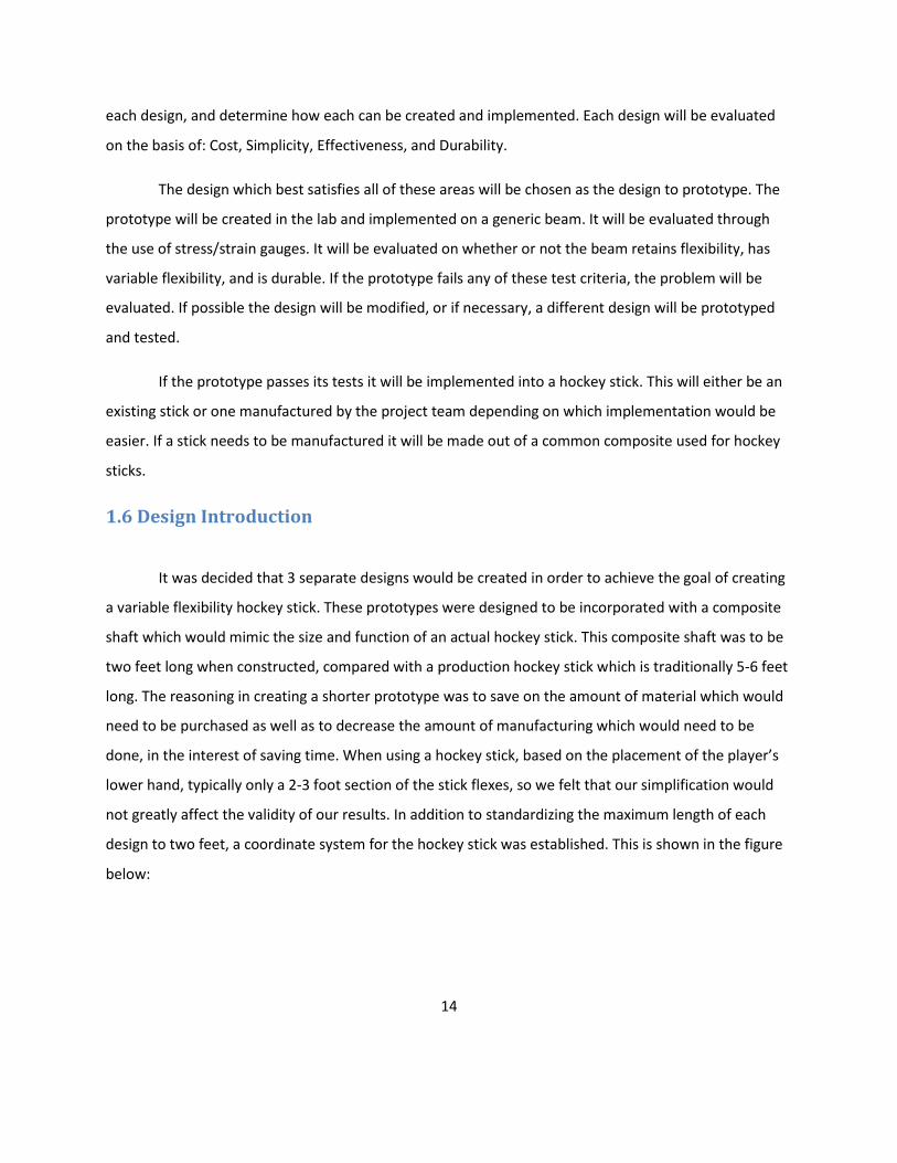
FR 3.1 is necessary because the assembly needed to be constructed in such a way that
everything could be assembled prior to its installation into the stick. This was done by designing a two
piece bearing block to hold the force increasing helix which is shown in the following figure.
Figure 10: Two Piece Bearing Block
This allows it to support the thinner sections of the helix so that it can prevent un-wanted translation of
the shaft. These bearing blocks, which support the entire helix, are attached to an upper plate,
designated “Plate A”. This plate is discussed in DP 3. Plate A provides a stable platform to attach all
other components to. The bearing blocks are threaded so that screws attach them to Plate A via
threaded holes within the bearings as described in DP 3.2. “Plate B” which is the lower force distributing
plate, is attached to Plate A using hollow tubes which slide around pins projecting off of plate A as
described in DP 3.4. This allows Plate B to translate in the Y – direction while still transmitting the shear
loads generated in the X direction. Finally, plate A is threaded so that machine screws can come through
32
holes in the hockey shaft and thread into Plate A, holding it on the hockey stick. The holes in the top
surface of the hockey stick will be relatively easy to line up with the holes in Plate A.
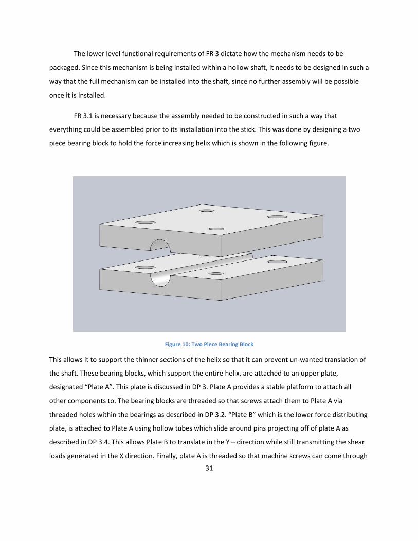
Table 5: Shear Friction Level 2 of FR and DP 4
FR 4.1 Match diameter of outer shell DP 4.1 The handle should not be significantly different from the rest of the stick
FR 4.2 Create enough space for a player’s hand DP 4.2 The handle should be large enough that a players is easily able to grab it
FR 4.3 Select level of flexibility DP 4.3 A ball spring, contained within the upper plate that interacts with one of six detents on the
interior of the handle
These FRs shown in the table above, describe the functions the control system which set the
level of flexibility for the stick. In order for the final design to be useful as a hockey stick, the controls
must be ergonomic, or else players will be unwilling or unable to use it.
FR 4.1 ensures that the dimensions of the handle were not much larger than the traditional
outside diameter of a hockey stick. This is because if the handle is too much larger than the outside of
the stick, it will be uncomfortable for the player to hold, since their hand is kept at the top of the stick.
FR 4.2 kept the total height of the handle small enough that it would not be un-wieldy, yet would still be
able to be manipulated by the player. The controls also needed a definitive means of selecting the level
of flexibility desired as shown in FR 4.3. The flexibility was set via a spring plunger, a pre-fabricated
device available which requires a pre-determined amount of force to push a ball bearing out of a groove,
which would then permit motion. The technical drawing of this device, provided by Mc-Master Carr, is
shown below.

33
Figure 11: McMaster-Carr Spring Plunger
The handle of this design had 6 such grooves to correspond with 6 levels of flexibility. A spring
plunger with a force of 2.3 pounds was used, as this would be easy for a player to over-come via rotation
but enough that movement of the stick would not cause an accidental change in the level of flexibility.
These spherical grooves are shown in the following figure.
Figure 12: Shear Friction Handle
34
Initially the handle was designed as having a fixed spring which would always return the
mechanism to its lowest setting. This would require the player to maintain a constant rotation of the
handle in order to obtain the desired flexibility. This idea was dropped due to the extra effort needed by
the player to maintain the level of flexibility and due to the fact that there would be no feedback
regarding which level of flexibility was selected.
3.2.3 Level 3 Decompositions
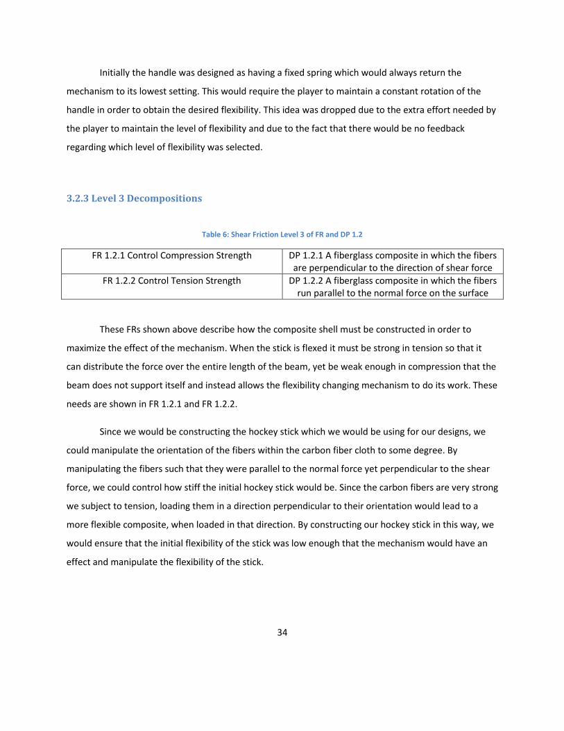
Table 6: Shear Friction Level 3 of FR and DP 1.2
FR 1.2.1 Control Compression Strength DP 1.2.1 A fiberglass composite in which the fibers are perpendicular to the direction of shear force
FR 1.2.2 Control Tension Strength DP 1.2.2 A fiberglass composite in which the fibers run parallel to the normal force on the surface
These FRs shown above describe how the composite shell must be constructed in order to
maximize the effect of the mechanism. When the stick is flexed it must be strong in tension so that it
can distribute the force over the entire length of the beam, yet be weak enough in compression that the
beam does not support itself and instead allows the flexibility changing mechanism to do its work. These
needs are shown in FR 1.2.1 and FR 1.2.2.
Since we would be constructing the hockey stick which we would be using for our designs, we
could manipulate the orientation of the fibers within the carbon fiber cloth to some degree. By
manipulating the fibers such that they were parallel to the normal force yet perpendicular to the shear
force, we could control how stiff the initial hockey stick would be. Since the carbon fibers are very strong
we subject to tension, loading them in a direction perpendicular to their orientation would lead to a
more flexible composite, when loaded in that direction. By constructing our hockey stick in this way, we
would ensure that the initial flexibility of the stick was low enough that the mechanism would have an
effect and manipulate the flexibility of the stick.

35
Table 7: Shear Friction Level 3 of FR and DP 2.1
FR 2.1.1 Translate and increase force DP 2.1.1 A shaft profile shaped such that the profile gets larger as it is rotated, increasing the force in the plate below it
FR 2.1.2 Increase the force on a linear profile along the stick
DP 2.1.2 A series of different profiles forming a helix such that a rotation of the shaft causes more and more profiles to increase the normal force on the plates below them
These FRs describe how the system which increases the normal force, must operate. Since this
design required that a rotation of a shaft would both increase the force acting in the Y-direction as well
as increasing the number of locations at which this force increase was applied the further the shaft was
rotated, a special geometry to accomplish this goal needed to be designed. The mechanism must
translate the rotation the helical shaft provided by the player and transform it into a force in the Y
direction so that there is a greater transmission of the shear forces. The increase in shear force was also
designed to progress up the shaft of the hockey stick, allowing a greater range of flexibilities for the
stick.
First, a profile was designed so that a portion of the profile could not reach Plate B from the
center of the shaft, which was in-line with the bearings, as required in DP 2.1.1. The distance from the
top of Plate B to the center of the shaft was determined, as this represented the largest diameter which
the helix needed to be. A piece of metal of that size would press against Plate B and increase the
transmission of shear forces.
DP 2.1.2 requires a number of different profiles so that as the shaft was rotated, the
transmission of shear force would be increased at more locations along the length of the shaft. The
following figure shows the different profiles of the helix along its length.

36
Figure 13: Shear Friction Helix
These different profiles meant that a further rotation of the shaft was needed to cause different
sections of the neutral boundary to experience different amounts of shear transmission. This method
was hypothesized to allow for a wide range of flexibilities since more of the stick would become rigid the
more the helix was rotated.
Table 8: Shear Friction Level 3 of FR and DP 2.2
FR 2.2.1 Distribute Load DP 2.2.1 A plate the same size as the shear surface which will distribute the point loads provided by
the helix
FR 2.2.2 Limit movement to translation about Y-axis
DP 2.2.2 A tube on the plate into which pins from Plate A slide, preventing movement in all
directions except for Y
FR 2.2.1 is necessary the neutral must be distributed over the entire neutral boundary, instead
of just in one small area. This is because a distribution will ensure that any shear forces generated will
be transmitted throughout the entire stick so the mechanism can alter the flexibility. DP 2.2.1 is
necessary because a plate will be most effective at distributing this load because it can be the same size
as the entire neutral boundary. It is necessary for Plate B to be the same size as the neutral boundary

37
surface upon which it acts, since a shear force will be generated along the entire neutral boundary when
the stick is flexed. If it is stiff enough it will transmit the force provided by the small contact patch of the
helical shaft over a large area.
FR 2.2.2 states that this plate must be restricted to moving the in Y axis so that it can allow for
an increase and decrease in the normal force while still transmitting the forces generated at the shear
boundary. The forces generated at the shear boundary will attempt to move Plate B when the stick is
flexed. The plate must resist this motion by not translating in the X or Z directions. This is accomplished
through the use of a pin and tube system shown in DP 2.2.2. This allows the tubes, located on Plate B, to
slide on the pins located on Plate A, yet any other translation will cause interference, and will transmit
the shear load. This system is simple and easy to implement, yet effective.
Table 9: Shear Friction Level 3 of FR and DP 2.3
FR 2.3.1 Prevent translation along X DP 2.3.1 Bearing blocks which are attached to the shell of the hockey stick
FR 2.3.2 Prevent translation along Y DP 2.3.2 Bearing blocks which are attached to the shell of the hockey stick
FR 2.3.3 Prevent translation along Z DP 2.3.3 Sections of the helix on either side of the bearing which are too large to slide through the
hole
In order for the helical shaft to perform its intended function it only needs to rotate about the
Z-direction. Any other motion will not allow for an increase in normal force as needed. The system which
holds the helical shaft must provide ways which limit the helix’s translational movement in the X, Y and Z
directions.
The bearing blocks, which will attach to Plate A via machine screws, will prevent any translation
of the helical shaft in the X or Y directions as required by DP 2.3.1 and DP 2.3.2.
The helical shaft has smaller sections in between the larger helical profiles discussed in DP 2.3.3.
These thinner portions serve two roles. First, they ensure that the helix can be rotated smoothly in the
bearings. These thinner sections are cylindrical, and rotate more smoothly in the bearings than a helix
could. The grooves in the bearings on which the thinner part of the helix fit are precisely sized such that
the shaft will fit into them, and provide a sliding fit without too much resistance to rotation, which could
38
cause the mechanism to be hard to operation. In addition, the bearings are constructed out of nylon,
which is a plastic known for its lubricity. The friction between the nylon and the steel shaft should be
minimal, and eliminate any un-needed resistance to activating the mechanism. Also, the smaller
portions of the helical shaft are surrounded by the large profiles of the helix. The helix sections are too
large to fit into the bearings, and thus prevent the entire helical shaft from translating in the Z direction.
3.3 Shear Friction - Physical Integration
3.3.1 Finite Element Analysis
In order to test the hypotheses we had regarding this design, Finite Element Analysis was used
to test the CAD model we created. Using the ANSYS 12 workbench software would allow us to visualize
the deflections and stresses that the mechanism was subject to. It also allowed us to obtain
approximate values for the stress and deflection.
A few simplifications were made during the FEA testing process. The first was that the
mechanism would only be tested in the most rigid and least rigid positions. Since separate assembly files
had to be imported for each test, two separate files were created. One file represented the helix being
rotated out of the way, for the “flexible” position. The other assembly had the helix rotated to the fully
“rigid” position. This allowed us to test the ranges of deflection we were likely to see. The second
simplification was the used of solid bearing blocks. We felt that the relatively minor deflections caused
by a two piece bearing block would not influence our results, by the addition of extra components
would mean more processing time was required. The last simplification dealt with the carbon fiber
shaft. Since carbon fiber can have different material properties based on the directions of the internal
fibers, it is a hard material to simulate. Therefore, approximate values were used for the stick material in
the analysis.
In the simulation, one end of the stick had a fixed support and one end was free, to simulate
cantilevered bending. A remote force of 100N was placed on the end of the stick opposite the support.
Simulations of the “rigid” and “flexible” orientations of the model were run to find the total deflection in
each. The results are shown in the figures below.

39
Figure 14: Shear Friction FEA of Rigid Beam
40
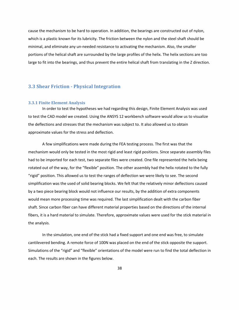
Figure 15: Shear Friction FEA of Flexible Beam
The results showed a 0.31038 mm deflection for the “flexible” setting and a 0.46951 mm
deflection for the “rigid” setting. This is interesting since this is opposite our hypothesis on how the
mechanism would work. It is interesting to note that there are different deflection values based on the
orientation of the mechanism. It could be that our intuition about how the mechanism works is wrong,
and that it actually operates the reverse of how we think it does. The other possibility is that the
simulation is not properly analyzing the function of the mechanism. Possibly the interaction between
Plate B and the helix, or Plate B and the hockey stick are not properly modeled. This could be due to a
limitation of how the program performs its calculations.
This analysis is useful since it shows that this mechanism can alter its flexibility, even if it does
work opposite of how we think it should. It is also worth noting the deflection values. It provides a basis
for what our future physical measurements may be. The deflection values are great enough that would
should be able to measure them with standard measuring equipment. The FEA analysis proves that the
design shows promise and should be investigated.

41
3.3.2 Tolerancing
A number of the components manufactured for this design had specific tolerances which
needed to be held. The bearing blocks needed to have a specific height so that they would not disrupt
the interaction between Plate B and the helix. The bearing blocks also needed a close fit with the shaft
of the helix so that there would not be unwanted movement, which would diminish the force increase
that the helix could provide.
Since the original rigid shaft was to be constructed to match the diameter of a traditional hockey
stick, this limited the amount of room which the mechanism had to fit into. The creation of the neutral
surface further reduced the amount of room for this mechanism. The height of the space the
mechanism was to be installed into was 0.46 inches. After the thickness of the top and bottom plates
were taken into account, it was decided that the total height of the two bearing halves needed to be
0.27 inches in order to allow Plate B enough room to move in the Y - direction when the stick was flexed.
The top half of the bearing had a height of 0.14” and the bottom half a height of 0.13”. The maximum
limit for the thickness of the bearing was 0.31” in which case it would be the same height as the helix.
However, this represents a theoretical maximum; a standard tolerance of +/- .005” would be much more
applicable. The table below shows the thicknesses of the manufactured bearing pieces.
Table 10: Shear Friction Bearing Thickness Tolerances
Piece #1 #2 #3 Avg.
Top 0.195” 0.176” 0.196” 0.189”
Bottom 0.157” 0.167” 0.166” 0.163”
Total 0.352” 0.343” 0.362” 0.352”
Clearly these parts were manufactured well over their desired tolerance. While this is undesired,
it was not unexpected. These oversized parts were the result of some problems encountered during
manufacturing. The primary reason was that, due to the flexible plastic and small dimensions, the work
piece had the tendency to flex during cutting. Due to this, there was a limit to how much material could
be removed without completely destroying the part. Also, there was a concern regarding the amount of
clamping force which could be exerted on such a small part. Due to this, the depth of cut was reduced so
that sufficient clamping force could be provided while avoiding crashing the cutting tool into the vice.

42
Due to these factors it was decided that the parts would have to be manufactured as they were and that
the outer diameter of the helix would have to be increased.
Another important tolerance was the relationship between the groove in the bearings in which
the shaft portion of the helix sat. According to the Machinery handbook, an RC4 running fit best
describes the type of fit needed between the shaft and the bearing, since the shaft needs to rotate yet
have minimal play. According to the table, for a .157 nominal diameter the hole has a minimum
tolerance of 0 and a maximum of +.0007”. The shaft has a tolerance of between -.0004” and -.0009” for
a minimum clearance of .0004” and a maximum clearance of .0016”. The following table shows the
diameter of the groove in each pair of bearing blocks.
Table 11: Shear Friction Bearing Groove Tolerance
Pair #1 Pair #2 Pair #3 Avg.
0.160” 0.162” 0.155” 0.159”
Our shaft, which was a nominal 4mm (0.157”) size, was measured to be exactly 0.157” in
diameter. The data gathered on the diameter of the grooves within the bearing blocks show that it was
not within an RC-4 class fit tolerance however, it is close to being the desired specification. When
observing the relationship between the helical shaft and the bearings it is noted that the shaft turns
freely within the bearing and that it has a minimal amount of excess play. The bearing blocks fulfill their
intended function within the mechanism, even if they are outside of the tolerance. The likely cause of
the parts being out of spec is that the bearings were designed to fit a 4mm (0.157”) diameter shaft.
However, when the parts were manufactured, a 4mm ball end mill was not available, so a 1/8” ball end
mill was used with a different cutting path. The in-accuracies from this cutting method most likely
caused the bearings to be slightly out of specification.

43
3.3.3 Diagrams
The following figures match the Functional Requirements from the design decomposition with images,
so that it is easier to understand how the mechanism operates.
FR 1 - Provide Composite Shaft
FR 1.3 - Control location of shear boundary
FR 1.4 - Control outer dimensions
Figure 16: Shear Friction FR 1 Diagram
1.3 1.4
1

44
FR 2.1 - Translate rotation into a force applied in the Y- direction increasing linearly along the length of
the stick
FR 2.2 - Transmit normal forces to shear boundary
FR 2.3 - Restrict helix movement to rotation about Z – Axis
Figure 17: Shear Friction FR 2 Diagram
2.1 2.2
2.3

45
FR 3.1 - Permit installation of helix into bearing blocks
FR 3.2 - Attach bearing blocks
FR 3.3 - Attach to composite shaft
FR 3.4 - Attach Plate B
Figure 18: Shear Friction FR 3 Diagram
3.3
3.1
3.2
3.4

46
FR 4 - Allow the user to control the normal force
FR 4.3 - Select level of flexibility
Figure 19: Shear Friction FR 4 Diagram
3.4 Shear Friction - Prototype Manufacturing
The creation of this design had many unique challenges when it came to producing a functioning
prototype. The main difficulty which needed to be overcome was the small sizes of each of the parts.
Since it was necessary that each part fit within a Carbon Fiber beam, of similar size to a hockey stick, the
4
4.3

47
overall size of each part was very small. Further complicating matters was the fact that the creation of a
surface at the neutral axis of the beam further reduced the available area.
For the creation of the bearing blocks, which would support the helical shaft and fix it to the
upper rail, the material Nylon was chosen, as it was light and had a low coefficient of friction, which
would allow the shaft to rotate easily within it. The bearing block needed to be split into two halves,
which would allow it to be assembled around the thinner part of the helical shaft. This entailed creating
two thin pieces, with a half circle trough running down the center. This trough was created through the
use of a 1/8th diameter ball end mill, and the mold roughing and finishing operation available in Esprit.
This ensured a smooth and uniform surface for the shaft to fit into.
Another major problem encountered during the creation of the bearing blocks, was the
tendency for the machining vice to impart too much force when clamping the part. In order to create
the blocks, the final shape was contoured out of an oversized stock piece. Then, the excess material by
which the part had previously been clamped was to be milled away. However, the thin cross section of
the finished block did not provide much surface area with which to clamp the part, and tightening the
vice with the force necessary to prevent the part from being pulled out also caused the part to flex
upwards as plastic was machined away. This caused a sloping cut on the back face of the bearing, which
would cause it to not lay flat against the top rail. This problem was solved by re-orienting the bearing
within the vice, so that the trough (which was where the material was at its thinnest) was perpendicular
to the vice jaws instead of parallel to it, which did not cause a stress concentration. In addition, an
aluminum backing plate was created at attached to the block using the threaded holes on them. This
further stiffened the block and allowed it to be machined without damage.
Another part which had a difficult manufacturing process was the helical shaft, which is vital to
the operation of this design. Due to the complex geometry of a shaft with a helix wrapping around it, the
use of a 4 axis CNC machine was initially considered. However, there were a number of properties of the
shaft that did not make this the optimal solution. As with the other parts, the small overall dimensions
of the shaft (4mm at the thinnest section and 8mm at the largest) would have allowed for excessive
deflection while machining. A fixturing device could have been made to support the back side of the
shaft while it was being cut, but multiple set-ups would have been constructed to cut the full helix

48
profile. Also taken into considering was how much time this process would have added to the overall
machining requirements. It was finally decided to construct an approximation of this shaft via simpler
means.
It was decided that by making a number of cylinders with an 8mm outer diameter, then shaping
them into profiles similar to that on the designed helix, the intended function of the shaft could be met.
By using the SL-10 CNC Lathe and drilling a center hole from either side of a steel cylinder, a 3 inch long
cylinder was made to the correct outer diameter of the helix. Then, by using the Mini CNC Mill, different
sections of the cylinder were cut away. These sections were then welded onto the 4mm rod in order to
create an approximation of the helical shaft. By combining quarter and half sections of the cut cylinders,
three distinct profiles were made.
The following figure shows the completed prototype.
Figure 20: Shear Friction Final Prototype Picture
3.5 Shear Friction - Results
The shear friction prototype was tested using the same methods as the other two designs. Due
to the nature of the prototype, it was decided to only test the mechanism in the positions which
theoretically yielded full flexibility and full rigidity. This was done to ensure that a discernable difference
existed between the two settings, which would show how effective this design was at changing the
flexibility of the stick. A diagram of the test set-up with location measurements is shown below.

49
Figure 21: Shear Friction Initial Test Schematic
Since the change from the rigid, carbon fiber hockey stick to the upper and lower carbon fiber
plates with fabric sides, some aspects of this design changed during testing. The upper plate, “Plate A”
was still secured to the upper carbon fiber strip. However, the lower neutral surface was comprised of a
properly sized piece of acrylic, which rested on top of the bottom strip of carbon fiber. The reasoning for
this was that, after seeing how stiff the initial carbon fiber hockey stick was, it was believed that a
hardened piece of carbon fiber which was the correct thickness would be too stiff and would diminish
the effects of this mechanism. Thus, a properly sized piece of acrylic was substituted so that it would be
more apparent if the mechanism was affecting the flexibility of the assembly. The results from testing
are summarized in the table below. All tables show the deflection values in millimeters.

50
Table 12: Shear Friction Test 1 Results
Test 1
Flexible Rigid
20g 40g 60g 20g 40g 60g
1
0 Seconds 0.2032 0.762 2.032 0.6096 1.9304 3.556
15 Seconds 0.2032 0.7874 2.0828 0.635 1.9812 3.6068
30 Seconds 0.2032 0.8128 2.1336 0.635 1.9812 3.6068
2
0 Seconds 0.1524 0.8636 1.9812 1.2192 3.2004 4.6228
15 Seconds 0.1524 0.9144 2.0066 1.27 3.2512 4.6736
30 Seconds 0.1524 0.9144 2.0066 1.2954 3.2512 4.699
3
0 Seconds 0.0508 0.7366 1.8796 0.9398 2.5654 4.064
15 Seconds 0.0508 0.7874 1.9304 0.9906 2.5908 4.1148
30 Seconds 0.0508 0.7874 1.9558 1.016 2.6162 4.1402
4
0 Seconds 0.1524 0.889 1.8542 1.27 2.9972 4.4196
15 Seconds 0.1524 0.9144 1.905 1.3208 2.9972 4.4704
30 Seconds 0.1524 0.9144 1.9304 1.3208 3.0226 4.4704
5
0 Seconds 0.0508 0.7874 1.8288 1.397 2.8956 4.3942
15 Seconds 0.0762 0.8128 1.8796 1.4478 2.9464 4.4196
30 Seconds 0.0762 0.8128 1.9304 1.4478 2.9464 4.445
Avg. 0.125307 0.83312 1.9558 1.120987 2.744893 4.24688
The results yielded data which directly opposed our anticipated results. The condition of the
mechanism in which the helical shaft increased the force on the neutral boundary, which represented
the mechanism being at it least flexible, showed much large deflections than when the mechanism was
theoretically at its most flexible. Since this phenomenon occurred during all tests when the mechanism
was in the “rigid” position, there is still a possibility that this mechanism is viable; it just does not
operate how we anticipated.
Due to the reversed operation and the incredibly small deflections observed, a second round of
testing was performed, using the same methods. The set-up diagram and results are shown below.

51
Figure 22: Shear Friction Revised Test Schematic
Table 13: Shear Friction Test 2 Results
Test 2
Flexible Rigid
20g 40g 60g 20g 40g 60g
1
0 Seconds 0.457 2.337 4.013 0.102 0.940 2.692
15 Seconds 0.508 2.489 4.089 0.102 1.041 2.794
30 Seconds 0.508 2.515 4.115 0.102 1.041 2.819
2
0 Seconds 0.711 2.692 4.724 0.229 1.803 3.658
15 Seconds 0.813 2.794 4.826 0.330 1.930 3.734
30 Seconds 0.838 2.819 4.851 0.356 1.956 3.759
3
0 Seconds 1.245 3.048 4.775 0.711 2.286 3.683
15 Seconds 1.321 3.099 4.826 0.737 2.362 3.810
30 Seconds 1.321 3.150 4.851 0.737 2.388 3.835
4
0 Seconds 1.372 3.251 4.877 0.838 2.413 3.785
15 Seconds 1.422 3.302 4.953 0.889 2.515 3.861
30 Seconds 1.422 3.327 4.978 0.914 2.515 3.886
5
0 Seconds 1.372 3.175 4.902 1.016 2.540 3.835
15 Seconds 1.473 3.251 4.978 1.067 2.642 3.912
30 Seconds 1.473 3.251 4.978 1.067 2.667 3.912
Avg. 1.083733 2.96672 4.715933 0.612987 2.069253 3.598333
From this table we can see that the mechanism works as anticipated, larger deflections were
recorded when the mechanism was in the “flexible” position. While performing these tests, the
orientation of the helix was visually verified. Due to the results gathered in the second round of testing,

52
it appears that there was an error when collecting the first set of data. The most likely explanation is
that the helix was not rotated to the correct positions to be flexible and in-flexible. This would have
been the result of miss-marking how the shaft had to be rotated in order to correctly align the helix. The
second set of results fits the type of data we would expect. The amount of deflection relates to the
position where it was hypothesized that the mechanism would be more or less flexibility. Also, the
values of the deflections are consistent, and large enough that they seem logical. It was noted during
the analysis of this data that there appeared to be an increasing trend of the deflection of the beam. By
the end of testing, the “rigid” deflection was greater than the than the initial “flexible” deflection. While
the mechanism was still operating as anticipated, this trend was cause for concern. It was not
immediately clear why this trend existed. Upon further testing it was found that the beam which
comprised the upper support of the cantilever was not fully tightened. This allowed the beam to shift
slightly as the test shaft pressed upward on it. This error most likely caused the majority of the
deflection trend, since it shifted over time. Once it was tightened, more consistent results were
observed, as shown below.
Table 14: Shear Friction Test 3 Results
Test 3
Flexible Rigid
20g 40g 60g 20g 40g 60g
1
0 Seconds 0.432 1.778 3.175 0.203 1.168 2.413
15 Seconds 0.457 1.803 3.226 0.229 1.219 2.438
30 Seconds 0.457 1.829 3.251 0.229 1.245 2.438
2
0 Seconds 0.762 2.642 3.835 0.457 1.651 3.048
15 Seconds 0.787 2.642 3.861 0.483 1.702 3.048
30 Seconds 0.813 2.667 3.861 0.483 1.702 3.048
3
0 Seconds 1.118 3.048 4.318 0.965 2.413 3.632
15 Seconds 1.168 3.200 4.470 0.991 2.413 3.658
30 Seconds 1.194 3.251 4.470 0.991 2.413 3.658
4
0 Seconds 0.838 2.413 4.064 0.508 1.575 3.302
15 Seconds 0.864 2.438 4.115 0.533 1.626 3.378
30 Seconds 0.864 2.464 4.115 0.533 1.651 3.404
5
0 Seconds 0.965 2.845 4.369 0.965 2.032 3.480
15 Seconds 1.067 2.896 4.470 0.991 2.083 3.531
30 Seconds 1.067 2.921 4.496 0.991 2.108 3.556
Avg. 0.856827 2.589107 4.006427 0.636693 1.800013 3.202093

53
Table 15: Shear Friction Test 4 Results
Test 4
Flexible Rigid
20g 40g 60g 20g 40g 60g
1
0 Seconds 0.864 2.464 4.191 0.229 1.067 2.210
15 Seconds 0.889 2.540 4.216 0.229 1.092 2.261
30 Seconds 0.914 2.565 4.216 0.254 1.092 2.286
2
0 Seconds 0.457 2.007 3.683 0.406 1.372 2.438
15 Seconds 0.483 2.032 3.734 0.432 1.397 2.540
30 Seconds 0.508 2.032 3.759 0.432 1.422 2.565
3
0 Seconds 1.016 2.794 4.521 0.508 1.397 2.515
15 Seconds 1.092 2.845 4.572 0.533 1.397 2.515
30 Seconds 1.118 2.845 4.597 0.533 1.448 2.565
4
0 Seconds 1.118 3.175 4.572 0.356 1.270 2.489
15 Seconds 1.143 3.226 4.572 0.381 1.295 2.515
30 Seconds 1.168 3.226 4.597 0.406 1.295 2.515
5
0 Seconds 0.965 2.819 4.318 0.203 0.965 2.413
15 Seconds 1.016 3.023 4.369 0.203 0.965 2.489
30 Seconds 1.041 3.023 4.394 0.229 0.965 2.489
Avg 0.91948 2.70764 4.28752 0.3556 1.22936 2.45364
An additional variation in the deflections is most likely due to two factors. The first is the fact
that the support points of the cantilever will settle into the parts of the beam which the support. As the
beam is loaded, the initial components and materials can compress due to the pressure applied to them.
This would cause the deflections to be greater over time. Additionally, the constant loading and
unloading of the components can contribute to variations in deflections. Specifically the pins, which
connect plate A and plate B, can shift due to the fact that they are only held in by a press fit. Tighter
tolerances of these components would cause them to move less, and make the overall stiffness of the
beam more stable.
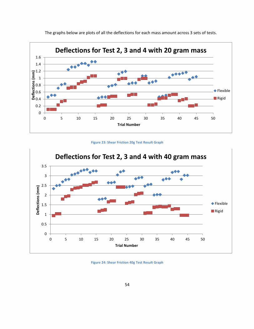
54
The graphs below are plots of all the deflections for each mass amount across 3 sets of tests.
Figure 23: Shear Friction 20g Test Result Graph
Figure 24: Shear Friction 40g Test Result Graph
0
0.2
0.4
0.6
0.8
1
1.2
1.4
1.6
0 5 10 15 20 25 30 35 40 45 50
De
fle
ctio
ns
(mm
)
Trial Number
Deflections for Test 2, 3 and 4 with 20 gram mass
Flexible
Rigid
0
0.5
1
1.5
2
2.5
3
3.5
0 5 10 15 20 25 30 35 40 45 50
De
fle
ctio
ns
(mm
)
Trial Number
Deflections for Test 2, 3 and 4 with 40 gram mass
Flexible
Rigid

55
Figure 25: Shear Friction 60g Test Result Graph
As can be seen, the 60 gram tests were the most stable in their deflections, with less variation
between trials. This is most likely due to the heavier amount of mass, smaller masses caused smaller
overall deflections which meant that small variations would have big effects. As seen in the 60 gram
graph, there is a jump at trial number 15, due to the tightening of the upper cantilever beam. As
discussed earlier, results after this point are more consistent, although there were still a number out
outlier points. Looking at the raw data, it can be seen that test 2 had a greater variation in the measured
deflections, due to the creep caused by the loose beam.
0
1
2
3
4
5
6
0 5 10 15 20 25 30 35 40 45 50
De
fle
ctio
ns
(mm
)
Trial Number
Deflections for Test 2, 3 and 4 with 60 gram mass
Flexible
Rigid

56
The average flexural rigidity (EI) was calculated through the use of the cantilevered beam
equation. The results are summarized in the table below.
Table 16: Shear Friction EI Results
Test Number Average EI “Flexible” (Nm2) Average EI “Rigid” (Nm2)
2 0.936 2.041
3 1.106 1.643
4 1.208 2.342
The data from test number one was not calculated, due to the error in the orientation of the
mechanism. The third round of testing shows a Rigid “EI” value which is much lower than observed in
test rounds two and four. This is due to some larger deflections during the “rigid” portion of testing. This
may be due to the helix not being oriented in the same manner as it was in tests two and four. There is
also the possibility that the mass and dial indicator were located in slightly different positions than was
recorded for that test. Despite this, the trials within these testing rounds were generally consistent, as
shown above. They did not exhibit the substantial creep as noticed in the second round of testing. In all
cases, the rigid setting was significantly stiffer than the flexible setting, so we feel confident about these
results, despite some fluctuation.
3.6 Shear Friction - Discussion
The results of the testing for this design indicate that this design may be viable in creating a
variable stiffness beam. Despite the problems in the initial round of testing, the second, third and fourth
rounds produced results which were consistent with our hypothesis on the operation of the mechanism.
This conclusion does not ignore the results of test 1 however, as doing so would present doubt in the
validity of our tests. The first round of testing did show a difference in the rigidity of the mechanism;
however it operated in the reverse of how it was anticipated to. As mentioned earlier, this is most likely
due to the helix being in a position different from what it was believed to be in. This would make sense
because there were differing amounts of deflection. If the mechanism had shown equal deflection

57
regardless of how the helix was oriented, that would cast much larger doubts over the validity of our
results.
The other concern presented during testing was the logarithmic deflection increase observed
during the second round of testing. As discussed earlier, during the third round of testing it was
observed that the upper beam of the cantilever was not properly tightened. After it was tightened the
results were much more consistent. There were some anomalies in the data, such as trials in which the
deflection was significantly lower. Overall though, the results were consistent and proved the operation
of the mechanism.
A number of the problems encountered while manufacturing this mechanism need to be
overcome to truly evaluate its effectiveness. The primary difficult was the construction of the helix. Due
to both the geometry and the size, the exact helix could not be created quickly, so a prototype was
made. The profiles of the individual pieces could not be exactly aligned, and the welding process warped
some of the pieces. Because of this, the helix does not rotate smoothly, and does not engage the
bottom plate in the exact locations it should. Had the helix been machined from a solid piece of
material, these alignment problems would have been overcome.
Also, the pieces which made up the outer diameter of the helix needed to be sized slightly larger
than the initial helix design, due to the fact that the bearing blocks were oversized. This led to limitation
on where the helix could have a large profile and not interfere with the upper plate. This limited the
number of locations to which the helix increased the force. Had the full helix been created, the
mechanism most likely would have been stiffer in the “fully engaged position”.
This mechanism was tested and shown to be successful while using the revised shaft. This is not
the same as testing the mechanism with a rigid box beam. Since current hockey sticks are constructed as
box beams, the difference needs to be considered when developing future versions of this design. Since
the shear friction mechanism itself is rigid, there is no reason why a hockey stick could not be made with
flexible side walls, provided this mechanism was located inside of them. However, this would be a
radical shift from how hockey sticks are currently fabricated. Further research would need to be done to
determine if this method will still allow the stick to function as hockey sticks do now. In addition, there
needs to be a consideration for player’s reaction to a stick which has flexible sidewalls, as this may

58
influence their playing style. Analysis and feedback from players would reveal if this mechanism has the
possibility of being integrated in a commercial product.
4.7 Shear Locking Conclusion
The results of the testing performed on this design seem to indicate that it is viable and that
further re-search and prototyping should be done. Due to the budgetary and time restraints imposed by
this project, it was not possible to further improve the design. There were drawbacks to the mechanism
which was tested due to complications introduced in the prototyping/manufacturing phase. However,
the prototype served its purpose, by being manufactured quickly and within budget and by providing
something which could be tested. Since these tests indicated that the design has potential, the
prototype has succeeded in its function.

59
Chapter 4: Shear Locking Design
4.1 Shear Locking – Concept and Theory of Operation
One method reviewed for altering the stiffness of a box beam was to change the geometry of
sections of the beam. Different geometric profiles have different bending stresses associated with them.
It was hypothesized that by changing the geometry of one face of the beam, the beam could be made
more or less flexible. This method would necessitate the creation of a mechanism that could change the
effective geometry of a profile.
The first part of the design that needed to be made was a fixed geometric profile that could be
easily controlled. It was decided that a toothed profile would create a flexible shape that could be
manipulated to become a less flexible solid box. This would be done by inserting other teeth from
another component into the slots created by the fixed profile.
Many ideas were considered to determine to how the profile geometry could be altered on
command. Sliding mechanisms, rotating components, and hinged features were discussed as possible
ways to solve the problem. Finally, it was decided that a rotating shaft with teeth on one half of the
diameter and a flat surface on the other half would be used to instantly change the profile along the
whole beam length. The teeth on the rotating shaft match the spaces between the teeth on the fixed
surface so they can mesh together. By using a toothed shaft, the profile inside the beam would be
quickly changed, which would theoretically create two distinct flexibility settings.
Once the design of the internal rotating shaft was created, the team developed ways to attach
the shaft to the hockey stick. This problem was solved by designing bushing blocks that would assemble
around the inner diameter of the shaft and be fixed to the inside of the hockey stick. The fixed toothed
profile and these bushing were designed to be put on guide rails which would allow for pre-assembly
and spacing of the components before sliding the whole assembly into the hockey stick. A solid model
of the prototype is shown in the following figure.

60
Figure 26: Shear Locking CAD Assembly
4.2 Shear Locking – Design Decomposition
4.2.1 Level One Decomposition Table 17: Shear Locking Level 1 FRs and DPs
FR 1 – Provide components DP 1 – Two components that interact to vary the flexibility
FR 2 – Lock and unlock the surfaces in shear DP 2 – A system to vary the shear modulus on the locking surfaces by rotating Component B
FR 3 – Contain the system that increases shear modulus
DP 3 – A hollow fiberglass or carbon fiber composite shell which contains and protects the locking system
FR 4 – Allow the user to control the shear modulus DP 4 – A handle located at the top of the hockey stick which the user can rotate
Two toothed surfaces, one rotating and one fixed, will be used in this design. Theoretically, if
the two sets of teeth are locked together and then flexed, the sides of the teeth will push against each
other and prevent further bending. The rotating shaft will provide the simplest method of ensuring that
the force applied to the fixed surface will be spread through the entire shear boundary, and will not be
concentrated in one place. Because of the interior dimensions of a hockey stick, the components of the
device will be put together before inserting them down the length of the shaft. The user will be able to
control the flexibility of the hockey stick through the use of a handle external to the rest of the design.
Because of the usual grip of a hockey player, the best location for the handle is at the top of the hockey
stick, where a hand is always located.

61
Because the different parts of the design work together to produce the final effect of altered
flexibility, the system is collectively exhaustive. Because the parts of the system each control a different
aspect of altering the flexibility, the design FRs are mutually exclusive.
4.2.2 Level 2 Decomposition Table 18: Shear Locking Level 2 FRs and DPs
FR 1.1 – Provide static Component A A component fixed along the z-axis with teeth that transmits loads to the outside shell of the stick
FR 1.2 – Provide moving Component B A component parallel to Component A which rotates about the z-axis, with a locking surface and an unlocking surface, which transmits loads to the outside of the stick or the neutral axis
FR 2.1 – Rotate Component B to locked or unlocked position
An axle connecting the teeth of the locking surface to rotate the teeth of Component B
FR 2.2 – Connect to user input A system to connect Component B to the user input
FR 3.1 – Control initial flexibility A shell to be constructed such that it does not alter the desired lowest flexibility of the hockey stick
FR 3.2 – Control outer dimensions Outside walls of the shell that do not exceed a dimension of 63 inches long
FR 3.3 – Attach to axle Bushings fixed to the outer shell and around Component B
FR 4.1 – Provide a profile that is similar in size to the outer shell of the hockey stick
A handle of similar size to the rest of the hockey stick
FR 4.2 – Form the handle such that it is long enough for a player’s hand
The length of the handle to closely match the width of a player’s hand while in a hockey glove
FR 4.3 – Select level of flexibility A system which allows the player to lock the components together or unlock them
The level 2 components of FR 1 deal with the various functions the device must satisfy, those
being a fixed feature and a moving feature. The z-axis described is the length of the hockey stick, and is
the axis to which the fixed component is bound. Component B rotates about its local z-axis, while
Component A is fixed along the z-axis.
In order for the mechanism to work, one of the components must rotate to switch between the
locked and unlocked positions. This will be accomplished by providing input from the user, so the device
must have some way to be attached to this input.

62
The level 2 components of FR 3 discuss the method to hold the device in place while on the ice.
The initial flexibility of the outside shaft must be controlled to allow the mechanism to work, as a
standard box beam has high bending strength on its own. Controlling the outer dimensions of the shaft
allow the players to easily use the new design, rather than forcing them to adapt to a new stick shape or
size.
The shaft needs a way to attach to the axle of the rotating beam, so the forces applied to the
beam can be evenly transmitted to the shell of the stick. This also helps keep the rotating component in
place so it does not get misaligned from the fixed component.
Having the player be comfortable with the size of components in the design is important to
allow for the most ease in using the device. It must be clear which flexibility setting the player chooses,
as hockey is a fast-paced sport and choices must be made quickly to determine which flexibility to use
and which is in use.
4.2.3 Level 3 Decomposition Table 19: Shear Locking Level 3 FRs and DPs
FR 1.1.1 – Provide boundary with Component B near the stick’s neutral axis
DP 1.1.1 – Solid sections that form the teeth, with the neutral axis of the stick in the middle of the teeth
FR 1.1.2 – Control initial flexibility DP 1.1.2 – Component A to be constructed such that it does not alter the desired lowest flexibility of the hockey stick
FR 1.1.3 – Prevent movement in all directions DP 1.1.3 – A fastening method that prevents movement in all directions
FR 1.2.1 – Provide locking surface DP 1.2.1 – A surface on Component B with teeth that match with the teeth in Component A
FR 1.2.2 – Provide unlocking surface DP 1.2.2 – A flat surface on Component B that does not interact with Component A
FR 1.2.3 – Provide boundary with Component A near the stick’s neutral axis
DP 1.2.3 – A system which holds Component B in the locked position
FR 1.2.4 – Control initial flexibility DP 1.2.4 – Component B to be constructed such that it does not alter the desired lowest flexibility of the hockey stick
FR 1.2.5 – Transmit loads at shear surface to outer shell
DP 1.2.5 – Bushings fixed to the outer shell and surrounding Component B which transmit forces
FR 1.2.6 – Restrict movement to z-axis DP 1.2.6 – Component B should only rotate about the z-axis

63
FR 1.2.7 – Rotate Component B DP 1.2.7 – An axle running through the locking teeth, controlled by the user, which positions Component B
FR 2.2.1 – Attach connection mechanism to Component B
DP 2.2.1 – A mechanism to connect to the axle of Component B
FR 2.2.2 – Attach connection mechanism to user input handle
DP 2.2.2 – A mechanism to connect to the user input
The level 3 components of FR 1.1 describe how the static Component A is to be constructed. It
needs to have a surface that interacts with Component B near the middle of the shaft. Component A
must have some degree of flexibility for the mechanism to work. Because this component is fixed,
movement in all directions must be controlled. The initial flexibility of the components is important, as
this plays a role in the accumulated flexibility of the sum of all components. The wording of DP 1.1.3
allows for different methods to fix Component A, such as screws or adhesive.
The components of FR 1.2 detail the roles that the moving part of the device must meet. The
mechanism must translate the rotation of the shaft into a force on the sides of the teeth of Component
A. There must be two profiles on the component to allow for the selection of flexibility. Component B
must be kept in the unlocked or locked position to prevent an unwanted change in the flexibility.
To connect Component B to the user input, it is first specified that Component B be attached to
an intermediate mechanism, then the intermediate mechanism connected to the user input handle. It
was determined that the intermediate mechanism could occur in two ways. The intermediate
mechanism could be a part of Component B if the length of the rotating shaft were extended past the
edge of the hockey stick to go straight into the user input. The other option would be to have a linkage
that connects Component B and the user input.

64
4.2.4 Level 4 Decomposition Table 20: Shear Friction Level 4 FRs and DPs
FR 1.1.2.1 – Control shear strength DP 1.1.2.1 – A fiberglass or carbon fiber composite in which the fibers are perpendicular to the direction of shear force
FR 1.1.2.2 – Control tension strength DP 1.1.2.2 – A fiberglass or carbon fiber composite in which the fibers run parallel to the normal force on the surface
FR 1.2.4.1 – Control shear strength DP 1.2.4.1 – A material strong in the direction of shear force
FR 1.2.4.2 – Control tension strength DP 1.2.4.2 – A material strong in the direction of normal force
FR 1.2.6.1 – Restrict movement in x-axis DP 1.2.6.1 – Bushings fixed to the outer shell and around the axle of Component B which restrict movement in x-axis
FR 1.2.6.2 – Restrict movement in y-axis DP 1.2.6.2 – Bushings fixed to the outer shell and around the axle of Component B which restrict movement in y-axis
FR 1.2.6.3 – Restrict translational movement in z-axis
DP 1.2.6.3 – Bushings fixed to the outer shell and around the axle of Component B which restrict translational movement in z-axis
By controlling the shear and tension strengths of all components, the mechanism has a smaller
chance of breaking while in use. If the fibers are parallel to the shear force, the material could tear
when forces are applied. By putting the fibers perpendicular to the direction of shear, the component
would be much stronger. By restricting the directions in which Component B can move, the teeth on
this part are ensured to stay aligned with the teeth on Component A. The bushings in DPs 1.2.6.1,
1.2.6.3, and 1.2.6.3 are all the same components.

65
4.3 Shear Locking – Physical Integration
4.3.1 Assembly
FR 1.1 – Provide static Component A
Figure 27: Shear Locking FR 1.1 Diagram
FR 1.2 – Provide moving Component B
FR 1.2.1 – Provide locking surface
FR 1.2.2 – Provide unlocking surface
Figure 28: Shear Locking FR 1.2 Diagram
1.1
1.2
1.2.1
1.2.2

66
FR 1.2.6 – Restrict movement to z-axis
FR 2.2.1 – Attach connection mechanism to Component B
Figure 29: Shear Locking FR 1.2.6 Diagram
FR 2.2 – Connect to user input
FR 1.2.7 – Rotate Component B
Figure 30: Shear Locking FR 1.2.7 Diagram
1.2.6 2.2.1
2.2
1.2.7
Set screws would be placed
in these holes, but were not
drawn for the sake of
simplicity.

67
FR 3 – Contain the system that increases shear modulus
Figure 31: Shear Locking FR 3 Diagram
4.3.2 Tolerancing
All parts of this design had specific dimensions that needed to be adhered to for optimum use.
The bushings needed proper height, width, and length to provide the proper fixture for the rotating
shaft. The grooves in the bushings needed to be a specific distance from the wall of the block, to reduce
interaction between the Component B and the guide rail for the bushings. The fixed teeth needed to
have a tight tolerance to interact with the rotating teeth properly. While the widths of the guide rails
and fixed teeth are important for maintaining the normal size of a hockey stick, these dimensions were
the least important of the project.
Because all components needed to fit into a hockey stick, it was decided that the outer
dimensions of the cross section were not to exceed 25 mm x 22 mm. Because of the assembly process,
some parts did not fit together as well as they should have, so the largest actual width of the assembly is
26.93 mm. The height of the assembly is 21.60 mm, which is less than the desired outcome. The width
of the assembly being over the desired outcome did not prove to be much of a problem, as two
millimeters could be removed by making the guide rails thinner.

68
The bushings were designed to be 76 mm x 12.5 mm x 12 mm, with a tolerance of ±0.5 mm. The
measured dimensions for all blocks are shown in the table below. The heights of all the bushings are
less than the desired 12 mm due to the design and manufacturing process. The most probable reason
for this is that in the original design the measurement was supposed to be 11 mm. When making the
CNC code, the wrong CAD file was probably used due to similar labeling of files. Due to this, Component
B interacted with the bushing guide rail and caused rotation from the user to be more difficult than
expected. The guide rail flexed when hit by the rotating shaft, which created a curved profile rather
than a straight one along that surface.
Table 21: Shear Locking Bearing Block Tolerances
Bushing block # Desired length: 76 mm Desired width: 12.5 mm Desired height: 12 mm
1 74.67 mm 12.50 mm 10.96 mm
2 71.07 mm 12.69 mm 10.92 mm
3 75.93 mm 12.72 mm 11.09 mm
4 74.18 mm 12.60 mm 11.14 mm
5 71.10 mm 12.76 mm 11.16 mm
6 71.41 mm 12.85 mm 11.17 mm
7 74.45 mm 12.93 mm 11.33 mm
8 75.52 mm 13.01 mm 11.18 mm
The rotating teeth were designed to be 76 ± 0.5 mm long, with a 76 mm gap between them on
the rotating shaft. The measured dimensions for these features are shown in the table below. The
differences in lengths of the rotating teeth can most likely be attributed vibration of the CNC machine.
The teeth gaps are all about the same size as expected, but the teeth slid while the epoxy was setting,
causing the gaps to be larger.

69
Table 22: Shear Locking Rotating Tooth Tolerances
Rotating Teeth Feature # Desired Length: 76 mm
Rotating Tooth 1 75.53 mm
Rotating Tooth 2 75.94 mm
Rotating Tooth 3 75.74 mm
Rotating Tooth 4 75.01 mm
Rotating Tooth Gap 1 76.71 mm
Rotating Tooth Gap 2 76.79 mm
Rotating Tooth Gap 3 76.95 mm
The fixed teeth were designed to be 76 mm x 25 mm, with a tolerance of ±0.5 mm. The
measured dimensions for all fixed teeth are shown in the table below. The widths of all the fixed teeth
are less than the desired 25 mm, due to inaccuracies of using the laser cutter to form these parts. Teeth
2 and 4 were cut after being fixed to the guide rail to accommodate for the rotating teeth which slid
during the assembly process. This caused all gaps to be larger than expected.
Table 23: Shear Locking Fixed Tooth Tolerances
Fixed Teeth Feature # Desired Length: 76 mm Desired Width: 25 mm
Fixed Tooth 1 75.72 mm 24.64 mm
Fixed Tooth 2 73.03 mm 24.51 mm
Fixed Tooth 3 75.72 mm 24.49 mm
Fixed Tooth 4 73.37 mm 24.51 mm
Fixed Tooth Gap 1 77.85 mm N/A
Fixed Tooth Gap 2 79.82 mm N/A
Fixed Tooth Gap 3 76.66 mm N/A

70
4.4 Shear Locking – Prototype Manufacturing
To create the rotating shaft, the group chose to use aluminum. This material was favored for its
high strength and low weight. Originally, this part was to be made from one solid bar of aluminum, and
have all features machined from it. The teeth were to be made in a lathe, and the flat face done in a
milling machine. After reviewing the manufacturing procedure and the dimensions of the part, it was
realized that the 5 mm center diameter of the shaft might be too small and would cause the part to
break during the machining process.
This design setback was overcome by a new method of creating the shaft. Sections of 16 mm
diameter aluminum were cut to the correct length of 76 mm in a band saw and 5mm holes were drilled
through the centers of these sections on the lathe. After this, these tubes were put into a milling
machine and the flat surface was machined with a facing operation. A 5 mm diameter rod was pushed
through the holes in the tubes. The tubes were fixed in place at the correct distances from each other
with the use of a two-part epoxy applied to the outside of the 5 mm rod. To align the flat faces of the
teeth, each face was placed on a table while the epoxy was still wet. The shaft stayed in this position
until the epoxy completely set.
The bushings were made of nylon blocks. This material was chosen because of its light weight
and low coefficient of friction for easy rotation of the shaft within the bushings. The bushings were split
in half to be assembled around the 5 mm diameter sections of the rotating shaft. The groove was made
with a 5 mm ball end mill in the milling machine and was programmed with a contour path in Esprit.
Holes were added to the bushings to be able to connect them together and attach them to the guide
rail.
The guide rail for the bushings and the guide rail and teeth for the fixed profile were both made
from a plastic called delrin. These parts were made in the laser cutter. The first time the group tried to
make these parts, two passes with the laser cutter were made, and barely a dent was made in the
delrin. After adjusting the settings, the group was finally able to cut all the way through the material for
the outside profile. Because the through holes for screws in these parts were so small, the laser cutter

71
was unable to get all the way through the delrin for these features. This was solved by punching the
holes out of the parts with an awl after the laser cutting procedure was finished.
4.4.1 Component Models
The main component of this design, the rotating shaft, is shown in the figure below.
Figure 32: Shear Locking Rotating Shaft CAD Model

72
The fixed profile, with the teeth and guide rail for them, is shown in the next figure.
Figure 33: Shear Locking Fixed Profile CAD Model
The next part shown is a single bushing block. Two of these are attached together to hold a section of
the shaft in place.
Figure 34: Shear Locking Bushing Block Model

73
The bushing guide rail is shown below. The bushings are attached to this to allow for easy assembly.
Figure 35: Shear Locking Bushing Guide Rail Model
The bushings and shaft are shown together in the figure below to show the assembly of these
components.
Figure 36: Shear Locking Bushing and Shaft Assembly

74
4.5 Shear Locking – Results
The second method that the shear locking design was tested in was the same as the other two
designs. The components of the design were as they were in the first test. The completed assembly
was inserted into a three point bending fixture with circular supports, a dial indicator, and a singular S-
hook to hang weights from. The layout was as seen in the figure below.
Figure 37: Shear Locking Testing Schematic
During testing of this design, some problems occurred. The teeth of the fixed profile were
attached to the guide rail with the same epoxy used on the rotating shaft. While it bonded to aluminum
well, the epoxy did not bond to the delrin as sufficiently as we would have liked. During testing with the
first method, one of the fixed teeth broke off of the assembly. We continued testing with this missing
tooth, which seemed to alter the flexibility a lot. After this round of testing all fixed teeth were removed
and glued to the guide rail again with Gorilla Glue.
During testing using the second method, the Gorilla Glue started to make cracking noises. This
occurred when testing the design in the unlocked position after 15 seconds with the 60 g mass hanging
from the end. None of the teeth broke off during this test, and the cracking did not seem to affect the
results of the test at all. Results from all trials using both testing methods are shown in the tables
below.

75
Results from each trial, from both methods of testing, are shown in the tables that follow, with
deflections in mm. Each blue or white section represents one set of trial runs. The yellow highlighted
portions of data are test runs that support the group’s hypotheses. The values listed are the deflections
from the original position before the trial, in inches.
Based on the average deflections at the bottom of each column, as well as the data being
inconsistent, it is difficult to say with any certainty that the design works as well as it should. Less than
half of the data points support the hypothesis. In fact, based on the data, it could be suggested that the
locking mechanism works in the opposite way we thought, where the “locked” position would be more
flexible and the “unlocked” position would be less flexible.
Table 24: Shear Locking Initial Testing Results
Trials done using the vernier height gauge
Flexible Rigid
20g 40g 60g 20g 40g 60g
Trial 1
0 Seconds 2.921 9.042 12.217 0.838 2.515 4.953
15 Seconds 2.921 9.144 12.319 0.965 2.616 5.207
30 Seconds 4.928 9.144 12.675 1.067 2.769 5.639
Trial 2
0 Seconds 2.311 3.810 6.934 4.309 7.087 6.477
15 Seconds 2.413 4.064 7.188 4.309 7.087 6.579
30 Seconds 2.413 4.064 7.239 4.115 7.518 6.604
Trial 3
0 Seconds 1.956 6.071 15.723 5.486 8.719 17.399
15 Seconds 1.956 6.071 16.891 5.588 8.433 17.780
30 Seconds 2.311 6.325 17.018 5.867 8.738 18.542
Average 2.692 6.426 12.014 3.556 6.096 9.906

76
Table 25: Shear Locking Revised Testing Results
Trials done using the dial indicator
Flexible Rigid
20g 40g 60g 20g 40g 60g
Trial 1
0 Seconds 3.277 8.890 16.764 4.089 8.611 13.157
15 Seconds 3.404 9.042 16.891 4.115 8.636 13.208
30 Seconds 3.454 9.093 16.967 4.115 8.636 13.411
Trial 2
0 Seconds 5.359 11.049 18.491 4.470 8.661 13.208
15 Seconds 5.461 11.252 18.567 4.521 8.687 13.259
30 Seconds 5.486 11.278 18.745 4.521 8.687 13.284
Trial 3
0 Seconds 5.512 11.252 18.771 4.470 8.915 13.945
15 Seconds 5.588 11.303 18.898 4.496 8.915 13.945
30 Seconds 5.613 11.328 18.923 4.496 8.915 13.945
Trial 4
0 Seconds 1.524 6.096 12.675 4.648 10.592 16.789
15 Seconds 1.524 6.172 12.751 4.801 10.617 16.789
30 Seconds 1.549 6.198 12.776 4.851 10.643 16.789
Trial 5
0 Seconds 74.193 7.087 11.887 5.207 10.922 16.688
15 Seconds 2.972 7.137 12.802 5.258 11.024 16.739
30 Seconds 2.997 7.163 12.802 5.309 11.049 16.764
Trial 6
0 Seconds 2.261 6.985 12.827 4.140 9.246 11.684
15 Seconds 2.286 7.087 12.979 4.267 9.347 11.938
30 Seconds 2.311 7.137 13.005 4.293 9.525 11.989
Trial 7
0 Seconds 2.972 4.902 14.529 5.080 7.315 11.532
15 Seconds 3.073 4.953 14.605 5.207 7.366 11.557
30 Seconds 3.607 5.004 14.605 5.207 7.391 11.582

77
Trial 8
0 Seconds 4.064 12.954 15.011 4.572 8.763 13.665
15 Seconds 4.191 13.081 15.011 4.623 8.865 13.665
30 Seconds 4.242 13.132 15.011 4.648 8.890 13.691
Average 3.581 8.738 15.265 4.648 9.169 13.894
4.6 Shear Locking – Discussion
If more time were available, the group has changes to this design that we would try for
improved results. First, the delrin used in the guide rails and fixed teeth was hard to work with while
creating the parts. The group would try another plastic, such as acrylic or nylon, or a metal like
aluminum to reduce manufacturing efforts and increase strength. The delrin cracked in a few places
during the manufacturing procedure, so we fixed these cracks with epoxy.
While the initial design of the fixed profile called for a solid piece, the group instead made the
profile by forming the teeth separately and using epoxy to fix them to the guide rail. The reason for this
change was that the group thought there would be concentrations of stress in the corners of the profile
when the part would be in a flexed position. This change to include the assembled profile caused
alignment and manufacturing issues in the complete assembly of the hockey stick. For this reason, the
group would revert to the original design of a solid piece. One option to use this solid design would be
to add radii to the corners to remove the stress concentrators. Another option would be to calculate
the stresses that would occur in those corners and if they are negligible, keep the profile as designed.
The testing shows that the mechanism is not consistent in the way it works. Some trials had
very small deflections, while others with the same weight had much larger deflections. Some trials
worked the way we hypothesized, with the “locked” setting being more rigid than the “unlocked”
setting. Other trials did not work this way. One possible reason for the inconsistent data is the
deviation from the tolerancing requirements during the manufacturing procedure. Another possible
reason for the inconsistent data is the choice of materials used for the prototype. The plastics chosen

78
might not have had the initial stiffness that was desired, or the plastics might lose stiffness over time.
Further testing would need to be done with either or both of these suggestions to determine if these are
the causes of failure for this design.
4.7 Shear Locking – Conclusions
After completing testing, it is apparent that this design does not work as well as we would have
liked. In the 11 trials done with a mass of 60 g, three tests failed. With a 73% pass rate and
inconsistency between trials, the design would need a lot more work before it could be implemented in
any application. Parameters that could be tested to obtain improved results would be different
materials, closer tolerances, and improved manufacturing, assembly, and testing procedures. The fact
that most tests passed show us that this design could be feasible with more work.

79
Chapter 5: Variable Volume Design
5.1 Variable Volume - Concept and Theory of Operation
Another concept which was discussed for changing the flexibility of a box beam would be to use
the properties of liquids. When a straight tube is bent, the volume inside the tube decreases. If the tube
is not sealed, when it is bent, the decreasing volume would force the contents of the tube out through
the opening. If the tube is sealed, then in order for it to bend, the contents of the tube would have to be
compressed. Water requires such a large amount of force to be compressed, that it could be considered
incompressible when the forces from playing hockey are exerted on it. If it is incompressible, then when
trying to bend the tube, it should theoretically prevent that. In order to use this property to vary the
flexibility, it would have to be possible to seal or unseal the tube.
A few different ideas were researched to determine the best way to use liquids to vary the
flexibility. Initially it was thought that the flexibility could be varied by controlling the rate at which fluid
could flow in and out of the tube. Another idea was using one way valves to control the flow of water.
These would have been very useful designs because they would have allowed for continuously variable
flexibility, but these ideas were thrown out because they would only change how quickly the beam
could flex, but not how much it could flex. It was decided that using a single valve to control if water
could flow in or out would work the best. The functionality was limited because it allowed for only two
levels of flexibility.
To vary the flexibility, a tube would be contained inside the hockey stick. The tube would be
filled with a liquid. The tube would be sealed on the bottom and be attached to a valve at the top. In
order to make the stick rigid, the user would close the valve, sealing the liquid inside the tube. In order
to make the stick more flexible, the user would open the valve to allow the liquid to flow out of the tube
and into a second tube.

80
5.2 Variable Volume - Decomposition
5.2.1 Level One Decomposition
Table 26: Shear Friction Level 1 FRs and DPs
FR1 – Allow flexibility to vary DP1 – A mechanism that uses fluid pressure to
change the flexibility of a tube
FR2 – Control flexibility DP2 – A mechanism that allows user input to
control the flexibility
FR3 – Provide shaft DP3 – A composite shaft that contains and
protects the mechanisms
FR4 – Install mechanism into shaft DP4 – A means of containing the mechanisms in
the shaft
This design uses the properties of liquids to control the flexibility of the hockey stick. The
volume of a fluid is dependent on the temperature and pressure of that fluid. Assuming the temperature
of a fluid is not changing, then as the pressure on the fluid increases, the volume decreases. Fluids are
very resistant to compression so that a lot of pressure is required to change the volume of a liquid.
Theoretically, if a fluid is enclosed in and occupies the entierty of a container, then the pressure required
to crush that container is very large. This design relies on this law to control the flexibility of the hockey
stick.The shaft of the hockey stick, the mechanism that varies the flexibility, the mechanism that
controls the flexibility and the means of holding the mechanisms in the shaft comprise the entire system
and show that the method is collectively exhaustive. The disconnections between the roles and actions
of the different parts show that these FRs are mutually exclusive.

81
5.2.2 Level Two Decomposition
Table 27: Variable Volume Level 2 for FR and DP 1
FR1.1 – Hold quantity of fluid constant DP1.1 – A reservoir that contains the fluid to a
single quantity
FR1.2 – Allow quantity of fluid to change DP1.2 – A reservoir expansion that allows the fluid
change quantity
FR1.3 – Control if quantity is constant or not DP1.3 – A valve that controls if the fluid can flow
from the reservoid to the expansion
The second level of decomposition for FR1 are all related to functions that the mechanism must
be able to complete. For the concept behind this idea to work, the mechanism must be able to have two
states, a state where the quantity of fluid is held constand and a state where the quantity of fluid can
change. FR1.1 deals with holding the quantity constant while FR1.2 deals with the state where the
quantity can change. FR1.3 is what controls which state the mechanism is in.
Table 28: Variable Volume Level 2 for FR and DP 2
FR2.1 – Allow user input DP2.1 – A handle to allow the user control
FR2.2 – Control flexibility DP2.2 – A mechanism connecting input handle to
valve
The second level decomposition for FR2 all deal with the input from the user. FR2.1 is what
allows the user to choose the flexibility based on their needs. FR2.2 is used to take the user’s desired
flexibility level and translate that to the mechanism controlling the flexibility, the valve between the
controlled volume chamber and the expansion chamber.

82
Table 29: Variable Volume Level 2 for FR and DP 3
FR3.1 – Protect the mechanism DP3.1 – Carbon fiber planks
FR3.2 – Control elastic modulus DP3.2 – Fiber sheath
FR3.3 – Contain mechanism DP3.3 – The shaft must have inner dimensions
large enough to hold the mechanism
FR3 is the shaft of the hockey stick. The second level decomposition is made of the functions
that the shaft must complete. FR3.1 and FR3.2 are related to the material composition of the shaft so
that the shaft is flexible enough that the effects of the mechanism are not masked, while being rigid
enough to protect the mechanism and give the shaft enough rigidity to be usable. The required
dimensions of the shaft make up FR3.3 which must be large enough to contain the mechanism.
Table 30: Variable Volume Level 2 for FR and DP 4
FR4.1 – Prevent motion in the X direction DP4.1 – Brackets
FR4.2 – Prevent motion in the Y direction DP4.2 – Diameter of tube
FR4.3 – Prevent motion in the Z direction DP4.3 – Fixed block
FR4 is composed of the different requirements for holding the mechanism inside the shaft.
FR4.1 has to prevent the mechanism from moving around in the X-direction which is across the shaft
and can be accomplished by using brackets to fill the gap between the tube of the mechanism and the
wall of the shaft. FR4.2 has to prevent the tube from moving in the Y-direction. This was the easiest to
solve by simply making the outer dimension of the tube the same as the internal Y-dimension of the
shaft. FR4.3 has to prevent the mechanism from sliding up and down the shaft in the Z-direction. To do
this, the tube was fixed to the bottom of the shaft with a threaded hole and rod.

83
5.2.3 Level Three Decomposition
Table 31: Variable Volume Level 3 for FR and DP 1.1
FR1.1.1 – Allow space for fluid DP1.1.1 – A hollow tube to hold the fluid
FR1.1.2 – Contain fluid in chamber DP1.1.2 – A block to prevent fluid from flowing out
FR1.1.3 – Prevent fluid from leaking DP1.1.3 – Sealant to make chamber water tight
FR1.1 deals with all the functions required of the reservoir that holds fluid at a constant
quantity. FR1.1.1 designates the fluid container as a hollow tube. FR1.1.2 is required so that the bottom
end of the tube is blocked so that fluid cannot flow out of it. Sealant between the tube and block and
valve make up requirement FR1.1.3 which has to stop any fluid from leaking.
Table 32: Variable Volume Level 3 for FR and DP 1.2
FR1.2.1 – Allow space for fluid to flow into DP1.2.1 – A hollow tube for fluid to flow into
FR1.2.2 – Prevent fluid from spilling DP1.2.2 – A rubber seal on the top of the tube
FR1.2 deals with all the functions required of the reservoir that allows the liquid to flow out of
the constant quantity reservoir. FR1.2.1 is a hollow tube that fluid can flow in to. FR1.2.2 is a seal made
of soft rubber that blocks the top end of the tube. This prevents fluid from spilling out of the system.
Without this requirement, the user would have to frequently refill the stick.
5.3 Variable Volume - Physical Integration
5.3.1 Tolerancing
For this design, there were no strict tolerances. This design had only one moving part, the valve
between the bottom tube and the top tube. This part was purchased pre built so the group did not have
to determine tolerances for it. Another place where tolerances could make a difference was where the
tubes connected to the valve. The tubes and valve were purchased from a single manufacturer with

84
standard sizes so they would not leak. In order to ensure that there were no leaks, sealant was applied
to these locations. These two reasons made tolerancing inconsequential.
The position of the tube inside the hockey stick was the only place where tolerancing was used,
and even in this regard, it was barely used. For the tube to influence the flexibility of the hockey stick, it
had to be touching both the front and back of the hockey stick. This did not require specifically
measured tolerances, but merely checking for visual gaps between the tube and shaft. The tube also had
to not be able to slide back and forth inside the shaft so the braces to prevent this motion were
toleranced in the same manner as with checking to see if the tube was touching both sides of the stick,
visually.
5.3.2 Diagram
Figure 38: Variable Volume FR Diagram
FR1.1 – Hold quantity of fluid constant.
FR1.2 – Allow quantity of fluid to change.
FR1.3 – Control if quantity is constant or not.
4.3
4.1
1.1
1.3
1.2
85
FR4.1 – Prevent motion in the X direction.
FR4.3 – Prevent motion in the Y direction.
5.4 Variable Volume - Results
The first set of data for the variable volume design presented some interesting results. Looking
at the changes in height between data sets, it was apparent that this design did not produce consistent
results, predictable patterns or complete the goal. Depending on which trial it was, if the time and
weight were the same, the changes in height had huge variances even if the stick was kept in the same
state of locked or unlocked. Also, on some of the trials, it showed that the unlocked state was more rigid
than the locked state, which is the opposite of how it should theoretically be. During the acquisition of
this data, the mechanism was leaking extensively and the tube had a very predominant bend to it. The
collected data can be seen below.

86
Table 33: Variable Volume Results
The second set of data produced much more stable results. For all trials, the unlocked state of
the mechanism deflected more than the locked state. Also, the data showed a very consistent pattern.
Every fifth data point had significantly lower deflection than the other data points. These data points
coincided with when, during testing, the mechanism was turned over to bend in the opposite direction
of the previous five points. Disregarding the fifth data point, all of the remaining points are very
consistent, with little variance. While collecting this second set of data, the mechanism did not leak and
the tube was much straighter than during the first set of data points. The second set of data contained
more points that the first one and is summarized by the graph below.

87
Figure 39: Variable Volume Deflections with 20g Graph
0
1
2
3
4
5
6
7
8
9
10
0 5 10 15 20 25 30 35 40 45 50
Ave
rage
De
fle
ctio
n (
mm
)
Trial Number
Variable Volume Deflections with 20g Mass
Flexible
Rigid
Linear (Flexible)
Linear (Rigid)
88
5.5 Variable Volume - Discussion
During testing a couple things were noticed about the variable volume design. The first thing
noticed was that the mechanism leaked. During the first iteration of the mechanism, it would start
leaking after a couple trials. The longer testing continued, the faster the mechanism started to leak. At
the end of collecting a full set of data, the height of fluid left in the reservoir tube would have decreased
several inches. After a sealant was applied to the connectors between the tubes, the leaking decreased
drastically. The fabric would still be damp, but the mechanism would never drip, nor would the height of
the fluid in the reservoir tube have visibly dropped. Given more time, future iterations of this design
might try using seals and sealant to prevent leaks.
Another noticeable aspect of this design was that it had a significant amount of creep. Some of
this creep was likely due to the leaking of the tubes, but changing the tubes might have helped reduce
the creep. The tube that was used was a hard rubber hose covered in a fabric mesh. A more flexible
material might allow the pressure of the fluid to exert more of an influence on maintaining the rigidity of
the tube as opposed to relying on the tube itself. During the storage and shipping of the tube, it was
coiled and retained a curve despite attempts to straighten it. The curved tube was exerting an additional
force that could not be determined during testing. If the tube was more flexible, the tube would be less
likely to retain its curve.
The last change that would be implemented if there was more time would be to keep the
contents of the reservoir chamber under slight pressure. This would facilitate the flow of the liquid back
into the main tube when the shaft straightened out after being bent. This would in turn increase the
rate at which the shaft returned to its straight position.
5.6 Variable Volume – Conclusion
Based on the second set of data, this design is successful at varying the flexibility of a beam,
however it is not applicable for use in a hockey stick. The second set of data shows that the flexibility of
the beam is dependent not only on the state of the mechanism, but also on if the shaft has been bent
already and in which way the shaft had been bent. Also, in hockey, the shaft must spring back into
position quickly to allow the player to add additional force to their shots, but this design did not snap

89
back to its neutral position quickly, which means that it would not work well in a fast paced environment
such as hockey. It would be much more suited for applications where forces were applied and removed
slowly or more consistently such as for structural building materials.

90
Chapter 6: Discussion
Out of the three prototypes tested, the Shear Friction design was the mechanism most ready to
be implemented in a hockey stick. It always altered its flexibility by a consistent amount when tested.
The shear locking mechanism was most likely inconsistent due to its manufacturing tolerances. It cannot
yet be considered a failed design, and a re-manufactured prototype would most likely lead to more
reliable testing. The variable volume design is not well suited to a hockey specific application because it
did not “snap” back to the original position as expected. It may still be useful for a variable stiffness
beam in other applications requiring lower return rates, such as building materials.
The project itself can be considered successful. One prototype was successful in the intended
application, one was possibly useful for other applications, and the final prototype has possible reasons
for being inconsistent. The testing method provided useful information that is similar to what we would
expect these mechanisms to encounter when used in a hockey situation. It also provided questions
which could be used for further research.
The project was successful in providing education in a number of areas important to
engineering. Conceptual designs were created and refined using Axiomatic Design techniques. CAD
models and assemblies were created so that the parts could be analyzed and eventually manufactured.
Functional prototypes for all designs were created using a variety of computer controlled and manual
machining methods. This highlighted the importance of part design, tolerancing, design for
manufacturability, and practical machining skills. The designs for which this work was done were unique
and beyond any technology which currently exists. Designing a product in this manner allowed the
group to be creative in the design process, and to not be constrained by parameters of redesigning an
existing product. An experiment was designed to the test the hypothesis relating to our project. This
involved an analysis of the experimental data required, considerations regarding accuracy and
repeatability, and an analysis of the final data. Should further development and research show these
designs to be useful, a successful commercial product could be created.
Our mechanisms were not capable of altering the flexibility of the initial box beam. This opposed
our hypothesis that a mechanism which could be integrated into current hockey sticks could be made.

91
For testing new mechanisms, or refined versions of the existing mechanisms, further development of
the hockey stick itself should be done. The initial box beam was far too stiff to show the effects of the
mechanisms, but the flexible-side beams we created are not similar to a production hockey stick. A
thinner walled box beam may decrease some of the problems caused by our initial construction. Use of
the vacuum bag method of carbon fiber lay ups may have helped the beam to have thinner walls and
use less resin. This may increase the success of testing mechanisms within a box beam.
If creating a rigid box beam is not practical, further research should be done with regards to
creating a beam with flexible sides. Despite the fact that current production hockey sticks do not exist in
this configuration, the addition of an internal mechanism may mean that a stick with flexible sides is
viable. Such an outer stick configuration may be vital to the operation of a particular type of
mechanism. During our testing, we hypothesized that the best way to create a stick with flexible sides
would be to create two rigid plates out of carbon fiber, slide the carbon fiber fabric shaft over these
plates, and then use a thin strip of resin on the top and bottom to hold it in place. This was never tested,
and experimentation may reveal a more suitable method of attaching fabric sides to rigid top and
bottom plates. Additional, fabric materials other than uncured carbon fiber may prove more suitable for
the construction.
Further testing is another recommendation related to this project. A relatively simple method
was used for the prototypes created. Additional testing with other methods could reveal interesting
information, such as a change in flexibility depending on how fast the shaft is loaded. Additional testing
could be performed by actually having a player use a stick in a game situation. Analysis of the
biomechanics of a player using the stick could reveal advantages or disadvantages to each design. This
sort of testing would also reveal any improvements that would need to be made in order to make such a
hockey stick a viable commercial product. Testing using electronic sensors would provide real time data
regarding the stiffness of the stick and the effect of the mechanisms. This was not possible during this
project, due to technical difficulties with the data acquisition system. Obtaining a working data
acquisition system would lead to the use of strain gauges as well as electronic dial indicators. Use of
these devices, especially by using multiple gauges at one time, would greatly enhance the quality of data
regarding these mechanisms. Further testing in this way would be highly valuable to a future project.

92
Chapter 7: Conclusions
The final conclusions regarding the total project are as follows.
The stiffness of a beam can be varied based on an internal mechanism
The shear friction mechanism had different levels of flexibility based on its activation
The shear locking mechanism was inconsistent, likely due to manufacturing tolerances
The variable volume mechanism was not suited to a hockey stick application
None of the mechanisms designed were found in patent research
A functional hockey stick should be created to understand the effectiveness of the top designs
This project accomplished the majority of its intended goals. Not every design was proven to be
successful, but the rationale for creating three prototypes was to see which design would be most
successful, if any at all. All areas of the design process, from conception to testing, were accomplished to
a sufficient degree. Ideally, a full prototype hockey stick would have been created because the
application of the variable stiffness beam technology was chosen to be a hockey stick. Creating a
working hockey stick would have shown if the technology was useful in this specific application.
However, time constraints did not allow for a full prototype to be created. Everything else was
accomplished and the core mechanism was created and tested. This provides a good basis for future
research which will be able to expand upon groundwork laid out by this project. In essence, the concept
has been proven, but further work needs to be done if this is to be developed into a viable commercial
product.

93
Works Cited Aerospace Specification Metals Inc. (2010). ASM Material Data Sheet. Retrieved April 20, 2011, from
Aerospacemetals.com:
http://asm.matweb.com/search/SpecificMaterial.asp?bassnum=MA6061t6
Bird, T. E. (2000). Patent No. 6033327. US.
Brett P. Masters, M. C. (2002). Patent No. 6361451. US.
Li, S. (2008). A variable transverse stiffness sandwich structure using fluidic flexible matrix composite.
University Park : Pennsylvania State University.
Matson, B. (2009, January 29). Bit of a sticky situation: Composites often are at breaking point. Boston
Globe.

94
Appendix
Aluminum Bar Data and Graph
Aluminum Bar Data – Revised Testing Frame and Procedure
Table 34: Aluminum Bar Raw Data
Trial 0 Seconds 15 Seconds 30 Seconds 1 10.897 10.922 10.922 2 10.617 10.643 10.668 3 10.693 10.719 10.744 4 10.465 10.465 10.490 5 10.643 10.643 10.668 6 10.643 10.668 10.668 7 10.668 10.668 10.668 8 10.566 10.617 10.617 9 10.465 10.465 10.465
10 10.668 10.668 10.668 11 10.719 10.795 10.820 12 10.846 10.846 10.871 13 10.490 10.541 10.541 14 10.566 10.592 10.617 15 10.693 10.719 10.744 16 10.643 10.693 10.719 17 10.744 10.744 10.744 18 10.770 10.770 10.770 19 10.439 10.439 10.439 20 10.795 10.820 10.820 21 10.414 10.439 10.439 22 10.846 10.871 10.871 23 10.719 10.719 10.719 24 10.693 10.693 10.719 25 10.744 10.744 10.770
Mean: 10.658 10.676 10.687
All measurements are from dial indicator in mm with 20 gram weight.

95
Aluminum Bar Graph – Revised Testing Frame and Procedure
Figure 40: Aluminum Bar Data Graph
10.300
10.400
10.500
10.600
10.700
10.800
10.900
11.000
0 1 2 3 4 5 6 7 8 9 10 11 12 13 14 15 16 17 18 19 20 21 22 23 24 25
De
fle
ctio
n (
mm
)
Trial Number
Deflection of Aluminum - 20g
0 Seconds
15 Seconds
30 Seconds

96
Variable Volume Data and Graphs
Variable Volume Data – Initial Testing Frame and Procedure
Table 35: Variable Volume Initial Testing Raw Data

97
Variable Volume Data – Revised Testing Frame and Procedure
Table 36: Variable Volume Revised Testing Raw Data
Locked Unlocked
TRIAL 0
seconds 15 seconds 30 seconds Mean
0 seconds
15 seconds 30 seconds Mean
1 5.994 6.121 6.198 6.104 7.493 7.518 7.544 7.518 2 7.010 7.087 7.137 7.078 8.560 8.560 8.585 8.568 3 6.985 7.087 7.112 7.061 8.153 8.153 8.179 8.162 4 6.731 6.807 6.858 6.799 8.077 8.077 8.077 8.077 5 6.782 6.909 6.985 6.892 8.052 8.077 8.103 8.077 6 5.791 5.893 5.969 5.884 7.366 7.417 7.417 7.400 7 7.061 7.137 7.214 7.137 8.636 8.661 8.661 8.653 8 6.807 6.934 7.010 6.917 8.839 8.839 8.865 8.848 9 7.010 7.137 7.163 7.104 8.712 8.788 8.788 8.763
10 6.655 6.706 6.807 6.723 8.611 8.661 8.661 8.644 11 5.690 5.817 5.867 5.791 7.290 7.315 7.366 7.324 12 6.629 6.756 6.807 6.731 8.458 8.484 8.484 8.475 13 6.909 6.985 7.010 6.968 8.534 8.585 8.611 8.577 14 6.985 7.087 7.112 7.061 8.407 8.509 8.534 8.484 15 6.782 6.883 6.909 6.858 8.331 8.331 8.357 8.340 16 5.817 5.969 5.994 5.927 7.442 7.468 7.468 7.459 17 6.909 7.010 7.061 6.993 8.407 8.407 8.433 8.416 18 6.629 6.731 6.807 6.723 8.306 8.357 8.357 8.340 19 6.706 6.782 6.858 6.782 8.331 8.331 8.331 8.331 20 6.579 6.680 6.731 6.663 8.484 8.509 8.534 8.509 21 5.969 6.071 6.096 6.045 7.544 7.544 7.544 7.544 22 6.680 6.807 6.833 6.773 8.611 8.661 8.661 8.644 23 6.985 7.036 7.087 7.036 8.585 8.585 8.611 8.594 24 6.629 6.706 6.756 6.697 8.153 8.153 8.230 8.179 25 6.706 6.807 6.883 6.799 8.560 8.585 8.585 8.577 26 5.867 5.994 6.045 5.969 7.036 7.036 7.087 7.053 27 6.807 6.883 6.934 6.875 8.433 8.433 8.458 8.441 28 6.883 6.985 7.036 6.968 8.560 8.560 8.611 8.577 29 6.629 6.706 6.756 6.697 8.560 8.560 8.611 8.577 30 6.782 6.833 6.858 6.824 8.534 8.585 8.611 8.577 31 6.680 6.807 6.858 6.782 7.188 7.188 7.214 7.197 32 7.188 7.239 7.264 7.231 8.484 8.560 8.585 8.543 33 7.061 7.137 7.214 7.137 8.509 8.534 8.534 8.526 34 6.934 7.010 7.087 7.010 8.382 8.433 8.433 8.416 35 6.960 6.985 7.087 7.010 8.407 8.407 8.407 8.407 36 6.096 6.223 6.274 6.198 7.315 7.341 7.341 7.332 37 6.756 6.833 6.934 6.841 8.534 8.585 8.611 8.577

98
38 6.629 6.731 6.756 6.706 8.560 8.560 8.585 8.568 39 6.883 6.960 7.010 6.951 8.611 8.611 8.636 8.619 40 6.731 6.807 6.858 6.799 8.433 8.484 8.509 8.475 41 5.842 5.944 5.994 5.927 7.087 7.112 7.163 7.120 42 6.960 7.010 7.061 7.010 8.331 8.357 8.357 8.348 43 6.629 6.731 6.807 6.723 8.382 8.407 8.458 8.416 44 6.680 6.782 6.807 6.756 8.433 8.433 8.433 8.433 45 6.655 6.706 6.731 6.697 8.306 8.306 8.382 8.331 46 6.629 6.706 6.756 6.697 7.645 7.645 7.671 7.654 47 7.087 7.188 7.214 7.163 8.763 8.788 8.788 8.780 48 7.137 7.188 7.239 7.188 8.839 8.865 8.865 8.856 49 7.036 7.112 7.214 7.120 8.788 8.814 8.814 8.805 50 7.112 7.188 7.239 7.180 8.915 8.941 8.941 8.932
Mean: 6.682 6.773 6.826 6.760 8.260 8.282 8.302 8.281
All measurements are from the dial indicator in mm with a 20 gram weight.
Variable Volume Graph – Revised Testing Frame and Procedure

99
Figure 41: Variable Volume Revised Testing 20g Deflection Graph
0.000
1.000
2.000
3.000
4.000
5.000
6.000
7.000
8.000
9.000
10.000
0 5 10 15 20 25 30 35 40 45 50
Ave
rage
De
fle
ctio
n (
mm
)
Trial Number
Variable Volume Deflections with 20g Mass
Flexible
Rigid
Linear (Flexible)
Linear (Rigid)