Variable speed drives - LC Automation tru… · variable speed drives have fairly specific uses,...
20
Variable speed drives Introducing energy saving opportunities for business CTG006 Technology Guide
Transcript of Variable speed drives - LC Automation tru… · variable speed drives have fairly specific uses,...

Variable speed drivesIntroducing energy saving opportunities for business
CTG006 Technology Guide

Contents
Technology overview 02
Principle of operation 03
Other types of variable speed control 04
Benefits of VSDs 05
Applications for variable speed drives 06
Fans 07
Pumps 09
Air compressors 10
Selecting a variable speed drive 11
Alternatives to variable speed drives 13
Glossary 14
Next steps 16

Variable speed drives
Reducing energy use makes perfect business sense; it saves money, enhances corporate reputation and helps everyone in the fight against climate change.
The Carbon Trust provides simple, effective advice to help businesses take action to reduce carbon emissions, and the simplest way to do this is to use energy more efficiently.
This technology guide discusses variable speed drives (VSDs) and lists energy saving opportunities for businesses. It demonstrates how installing VSDs in appropriate applications could save energy, cut costs and increase profit margins.
0�
Technology Guide0�
Technology overview
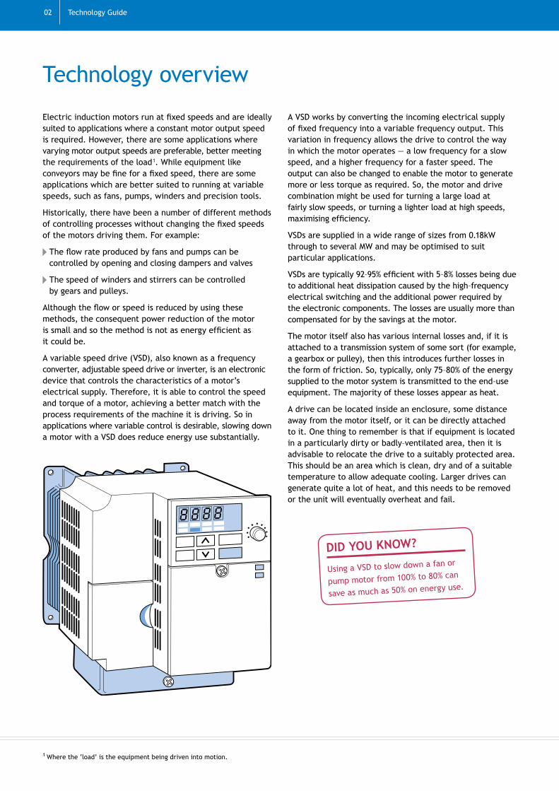
Electric induction motors run at fixed speeds and are ideally suited to applications where a constant motor output speed is required. However, there are some applications where varying motor output speeds are preferable, better meeting the requirements of the load�. While equipment like conveyors may be fine for a fixed speed, there are some applications which are better suited to running at variable speeds, such as fans, pumps, winders and precision tools.
Historically, there have been a number of different methods of controlling processes without changing the fixed speeds of the motors driving them. For example:
The flow rate produced by fans and pumps can be controlled by opening and closing dampers and valves
The speed of winders and stirrers can be controlled by gears and pulleys.
Although the flow or speed is reduced by using these methods, the consequent power reduction of the motor is small and so the method is not as energy efficient as it could be.
A variable speed drive (VSD), also known as a frequency converter, adjustable speed drive or inverter, is an electronic device that controls the characteristics of a motor’s electrical supply. Therefore, it is able to control the speed and torque of a motor, achieving a better match with the process requirements of the machine it is driving. So in applications where variable control is desirable, slowing down a motor with a VSD does reduce energy use substantially.
A VSD works by converting the incoming electrical supply of fixed frequency into a variable frequency output. This variation in frequency allows the drive to control the way in which the motor operates — a low frequency for a slow speed, and a higher frequency for a faster speed. The output can also be changed to enable the motor to generate more or less torque as required. So, the motor and drive combination might be used for turning a large load at fairly slow speeds, or turning a lighter load at high speeds, maximising efficiency.
VSDs are supplied in a wide range of sizes from 0.18kW through to several MW and may be optimised to suit particular applications.
VSDs are typically 92–95% efficient with 5–8% losses being due to additional heat dissipation caused by the high–frequency electrical switching and the additional power required by the electronic components. The losses are usually more than compensated for by the savings at the motor.
The motor itself also has various internal losses and, if it is attached to a transmission system of some sort (for example, a gearbox or pulley), then this introduces further losses in the form of friction. So, typically, only 75–80% of the energy supplied to the motor system is transmitted to the end–use equipment. The majority of these losses appear as heat.
A drive can be located inside an enclosure, some distance away from the motor itself, or it can be directly attached to it. One thing to remember is that if equipment is located in a particularly dirty or badly–ventilated area, then it is advisable to relocate the drive to a suitably protected area. This should be an area which is clean, dry and of a suitable temperature to allow adequate cooling. Larger drives can generate quite a lot of heat, and this needs to be removed or the unit will eventually overheat and fail.
� Where the ‘load’ is the equipment being driven into motion.
DID YOU KNOW?
Using a VSD to slow down a fan or
pump motor from 100% to 80% can
save as much as 50% on energy use.

Variable speed drives 0�
Principle of operation Although there are different types of electronic VSDs, they are all similar in design and consist of four basic components:
Rectifier — the rectifier changes the incoming alternating current (AC) supply to direct current (DC). The type of rectifier used can vary depending on the type of performance required from the drive. The rectifier design will influence the extent of the harmonic content present in the incoming supply. It can also control the direction of power flow.
Intermediate circuit — the rectified DC supply is then conditioned in the intermediate circuit, normally by a combination of inductors and capacitors. Over 98% of drives currently in the marketplace use a fixed–voltage DC link.
Inverter2 — the inverter converts the rectified and conditioned DC back into an AC supply of variable voltage and frequency. This is normally done with a semiconductor switch.
Control unit — the control unit gives and receives signals to the rectifier, the intermediate circuit and the inverter to correctly operate the equipment.
� VSD units are also commonly referred to as inverters. See the glossary at the end for further information.
Figure 1 Schematic of a VSD
Rectifier Inverter
Power
Control unit
Intermediate circuit

Technology Guide
Other types of variable speed controlThe most common type of variable speed control is a VSD used in conjunction with an electric motor. However, there are a number of other types of variable speed control device. Some examples are described below:
Integrated variable speed motors
A recent trend among motor manufacturers has been to develop a motor with an integral VSD. These packages are typically available in sizes ranging from 0.75kW through to 11kW. The major advantages include:
Reduced control panel space
Simplified installation
Straightforward electromagnetic compatibility compliance
Integration of motor and drive.
These can lead to greater cost savings over the life of the motor. In terms of efficiency, integrated variable speed motors have the same energy saving benefits as a non–integrated motor and VSD. However, because they are compact and easy to install, integrated types are becoming ever more popular in the heating, ventilation and air conditioning (HVAC) and pumping markets.
Switched–reluctance drives
These machines consist of a switched-reluctance motor and dedicated electronic controller. Their performance is similar to that of a conventional induction motor and VSD. In addition, they are capable of very high–speed operation (up to 100,000rpm). These devices have an energy efficiency performance similar to, and in some cases exceeding, that of an induction motor with a VSD. However, they are a relatively undeveloped technology and, as such, are much more expensive.
Other disadvantages of switched–reluctance drives are:
They can be very noisy
They need an electronic controller to work
If any faults develop, operation of the whole unit is affected, whereas an induction motor can keep running (albeit at full speed) if its VSD develops a fault.
Switched–reluctance drives tend to be used in niche markets, such as in some washing machines.
DC drives
These machines consist of a DC motor and dedicated electronic controller. DC motors/drives operate from a different type of electrical supply than AC motors/drives and as such have different characteristics.
Some of the benefits of DC drives are:
They are less complex than AC drives with a single power conversion from AC to DC
They are usually less expensive for most power ratings
They have a long tradition of use as adjustable speed machines, so a wide range of options has evolved for this purpose
DC regenerative drives are available for applications requiring continuous regeneration for overhauling loads such as driving shears. AC drives with this capability would be more complex and expensive
They are capable of providing starting and accelerating torques in excess of 400% of rated power and so may be more appropriate for applications such as starting up a mixer while it is full
They tend to be quieter than some AC drives which may produce audible motor noise, which could be undesirable in some applications.
However, there are some disadvantages when compared with AC drives:
DC drives tend to require more maintenance than AC drives
AC motors are better suited for high–speed operation (over �,500rpm) since there are no brushes, and commutation is not a problem
Special AC motor enclosure types are more readily available at lower prices when the operating environment is wet, corrosive or explosive.
Efficiency–wise, the performance of DC drives is similar to that of a conventional induction motor with a VSD. DC drives were the main form of variable speed control before the advent of VSDs. They are still in use today in specialist applications where high starting torques and variable speeds are required, such as pulsating loads, shears, bending rolls, plunger pumps, conveyors, elevators and crushers.
04

Variable speed drives 05
Multiple speed motors
These are AC induction motors that have been designed to have between two and four distinct operating speeds. One way to achieve this is through connecting the electrical supply to different winding configurations within the motor, resulting in different operating speeds. Multiple speed motors are most appropriate for applications where a system must operate at a small number of predefined speeds, such as a ventilation system operating at either a high or low setting.
Mechanical variable speed drives
These use mechanical means to convert a fixed–speed motor output into a variable speed output. This is typically achieved through the use of adjustable belt and pulley mechanisms or through metal roller mechanisms with adjustable diameters. These devices have inherent mechanical losses and so are not as energy efficient as electronic devices. Additional losses can be up to 20% more than electronic devices.
Hydraulic variable speed drives
These use hydraulic oil as a medium through which the torque is transmitted to the output. They have higher inherent mechanical and hydraulic losses than mechanical variable speed drives, so are not as energy efficient as electronic VSDs.
There are many different designs including hydrostatic drives, hydrodynamic drives and hydro–viscous drives. Hydraulic variable speed drives have fairly specific uses, for example, in the automatic transmission system of motor cars.
Benefits of VSDs Not all applications will benefit from variable control, but where it is needed, the main benefits of VSDs are:
Improved process control and hence output product quality
Programmable soft starting, soft stopping and dynamic braking, which reduce excessive stresses being placed on the motor and, therefore, extends its life
Wide range of speed, torque and power output giving a greater degree of control. For example, the electronically controlled VSD has the ability to set various parameters such as:
— Allowing differing acceleration rates for different speed changes
— Having the ability to increase/decrease the torque output at different speeds
Improved efficiency through an increase in the power factor of the system. This means that more of the current drawn is actually used to drive the load, making it more efficient
Dynamic response comparable to DC drives leading to better control
Energy savings in many applications. There are a number of different types of application where it is possible to reduce the speed of a motor while keeping the same outcome (such as in ventilation systems designed to satisfy a building’s maximum occupancy). In most cases, installing an electronic VSD is the most efficient method of doing this.
There are also some disadvantages in using VSDs mainly related to their suitability for particular applications. Consider these before installing a VSD to make sure that energy and cost savings are realised. Assess the load type carefully, and also refer to ‘Alternatives to variable speed drives’ section on page ��.

Technology Guide
Over two thirds of the entire industrial electricity consumption in the UK is due to electric motors. Many industrial sectors have discovered the benefits of using VSD control in a wide variety of applications. Businesses in the commercial and public sectors can also utilise the benefits of VSDs, largely in applications involving pumps and fans, such as ventilation and air conditioning systems, combustion air for boiler systems, chillers and water–pumping systems.
The potential for energy saving through the use of VSDs is dependent on the characteristics of the load being driven.
There are three main types of load:
Variable torque. On loads of this type (for example, fans and pumps), any speed reduction will save large amounts of energy (that is, a �0% speed reduction will result in a 50% power saving). This is because the torque varies with the speed squared, and the power varies with the speed cubed. This means that variable torque loads offer the greatest potential for energy saving.
Opportunities to look for:
Fans
Pumps.
Constant torque. On loads of this type (for example, conveyors and air compressors), torque does not vary with speed, and the power is directly proportional to speed. In essence, this means that the power consumed will be in direct proportion to the useful work done (that is, a 50% speed reduction will result in 50% less power being consumed). Although the potential energy savings from speed reduction are not as large as that with variable torque loads, they are still worth investigating as halving the speed can halve the energy consumed.
Opportunities to look for:
Conveyors
Air compressors
Crushers.
Constant power. On loads of this type (for example, machine tools and centre winders), torque varies with speed, but power is constant. In essence, this means that there will rarely be any energy saving for any reduction in speed.
Opportunities to look for:
Machine tools
Centre winders.
Figure 2 illustrates the relative energy saving potential of the three load types explained above.
The most energy intensive applications for motor–driven equipment in the UK are:
As Figure 3 below shows, the largest applications for motor–driven power in the UK, centrifugal pumps and fans have the greatest potential energy savings through appropriate use of VSDs. Coupled with the fact that pumps and fans are also variable torque loads as explained earlier, they have the greatest potential to save the largest amounts of energy.
Speed (%)Variable torque Constant torque Constant power
Ener
gy s
avin
gs (
%)
100
80
60
40
20
010 20 30 40 50 60 70 80 90 100
Figure 2 Energy saving from different load types
0�
Applications for variable speed drives
VSDs have the potential to make energy savings and increase profitability in almost every sector of UK business.
Figure 3 Applications for VSDs
Fans 23%
Air compressors 8%
Other compressors 14%
Conveyors 8%Other 16%
Pumps 31%
Pumps — ��%
Fans — 23%
Air compressors — 8%
Other compressors — 14%
Conveyors — 8%
Others — 16%.

Variable speed drives
FansAlthough dampers are often used to regulate the output of fans, reducing the speed of the fan is a much more energy efficient way of achieving the same effect. This is illustrated by the graph below (Figure 4).
Figure 4 Comparison of speed reduction in fans using dampers and VSDs
With damper control, the input power reduces as the flow rate decreases. However, under VSD control, the variable torque characteristic of the fan means that the relationship between flow and the speed of the fan is such that the input power reduces in a cube law relationship with the speed reduction. This can be seen by the graph, where the energy expended using a VSD is significantly less than that of damper–controlled motors. It also shows one of the limitations of a VSD, in that it will not normally be able to reduce the flow all the way to zero, but will only slow down as far as 20–30% (depending on the specification of the VSD and motor).
This type of fan application could be used in industrial cooling, commercial ventilation systems and combustion–air control systems for boilers.
As well as being a more efficient use of power, using VSDs in fan applications can also result in reduced noise in heating and ventilation air–duct systems due to the elimination of dampers. Making flow–rate changes in a damper system can lead to unwanted vortexes appearing in the airflow, which create noise and vibration in addition to the mechanical noise generated from the damper changing position. In a VSD system, making flow–rate changes generally only results in slight changes to the noise levels, which are normally undetectable to the ear. Figure 5, overleaf, demonstrates this.
fact:Reducing fan speed not only reduces
energy consumption but may also
reduce noise and vibration.
Flow rate (%)Damper VSD
Inpu
t po
wer
(%
)
100
80
60
40
20
0
Flow rate (%)Damper VSD
Inpu
t po
wer
(%
)
120
110
100
90
80
70
60
50
40
30
20
10
0 10 20 30 40 50 60 70 80 90 100
Note: Because of the losses inherent in VSDs, there is a point where they will be less efficient than dampers. This is around 92%-95% and is not shown on this simple graph.
07

Technology Guide
In the first diagram (a), flow is controlled by a damper, which is informed by a sensor (in some applications this could be a flow meter). The motor continues to operate at a constant speed regardless of flow required. In addition, some kinds of dampers, such as butterfly valves, can cause adverse vortexes in the flow.
In the second diagram (b), the pressure sensor is connected directly to the VSD which slows the motor when required. As well as leading to better automatic control of the motor’s speed, the adverse flow conditions are also improved.
(a): A typical fan and motor with flow controlled by a damper
Damper(can be located
at inlet or outlet)
Air flow
Motor
Energy input (no variable control)
Pressure sensor to measure flow here to control damper
(b): A typical fan and motor with flow controlled by a variable speed drive
Air flow
Motor
VSD
Energy input (via variable control)
Meter sends signal to VSD to increase or decrease speed of the motor
Pressure sensor links directly to VSD
08
Figure 5 Flow rate changes using dampers compared with using VSDs

Variable speed drives
Pumps In a similar way to using damper control in fan applications, using throttle control for pumping applications results in a poor efficiency as the pump is not being run at its design point. This is particularly true for applications with a steep flow/head characteristic, where there is a high static head such as in underfloor heating circuits, geothermal pumps and for small pumps. Further details on this will be available from equipment suppliers.
Using a VSD to control the pump rather than using simple throttle control can result in significant power — and therefore cost — savings. This is illustrated in the graph, right, where the broken line indicates the power input to a fixed–speed device and the solid line indicates the power input to a VSD. The shaded area represents the power saved by using a VSD for a given flow.
It is important to note that on systems with a high static head (for example, boiler feedwater pumps), where the pump must overcome the inherent resistance of the system before any flow starts, the benefits of using VSDs will be slightly reduced. This is because the additional resistance affects the relationship between the speed of the pump and the flow. Factor this into any calculations and consult an equipment supplier for further information if needed.
Typical examples of pump applications for VSDs include moving hot water in HVAC systems, boiler feedwater pumps and product flow pumps, such as chemicals or inks.
Note: To be strictly accurate, there is a crossover point where a VSD can use more energy than a fixed speed power input. This is because of the losses inherent in VSDs which are not balanced by savings when incorrectly used.
0�
Flow (%)
Pow
er (
%)
Power saved
10 20 30 40 50 60 70 80 90 100
100
90
80
70
60
50
40
30
20
10
0
Fixed speed power input Power input to drive
0
Figure 6 Power saved using a VSD in a pump
�0 Technology Guide
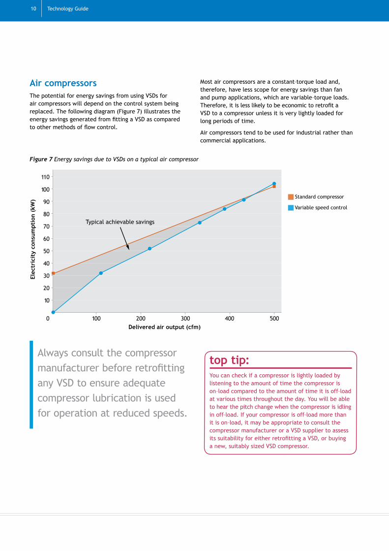
Air compressors The potential for energy savings from using VSDs for air compressors will depend on the control system being replaced. The following diagram (Figure 7) illustrates the energy savings generated from fitting a VSD as compared to other methods of flow control.
Most air compressors are a constant–torque load and, therefore, have less scope for energy savings than fan and pump applications, which are variable–torque loads. Therefore, it is less likely to be economic to retrofit a VSD to a compressor unless it is very lightly loaded for long periods of time.
Air compressors tend to be used for industrial rather than commercial applications.
Always consult the compressor manufacturer before retrofitting any VSD to ensure adequate compressor lubrication is used for operation at reduced speeds.
Delivered air output (cfm)
Elec
tric
ity
cons
umpt
ion
(kW
)
Typical achievable savings
Standard compressor
Variable speed control
Figure 7 Energy savings due to VSDs on a typical air compressor
top tip: You can check if a compressor is lightly loaded by listening to the amount of time the compressor is on–load compared to the amount of time it is off–load at various times throughout the day. You will be able to hear the pitch change when the compressor is idling in off–load. If your compressor is off–load more than it is on–load, it may be appropriate to consult the compressor manufacturer or a VSD supplier to assess its suitability for either retrofitting a VSD, or buying a new, suitably sized VSD compressor.

Variable speed drives ��
VSDs may be able to offer significant energy saving opportunities for specific applications. However, when considering fitting a VSD to a motor, care must be taken to ensure that the drive is really needed, that it is used in the best place and that it is being used correctly to provide the best energy saving advantages. This section provides guidance on issues to take into account when considering the installation of a VSD as well as providing further ways to save energy through the use of variable speed control.
When considering fitting a VSD to a motor, there are a number of issues to consider:
Type of torque
Whether a VSD is necessary
Size required
Type of control needed
Potential savings.
These are discussed below.
What type of torque load will be controlled?
As mentioned previously, the largest energy savings can be achieved from variable–torque loads such as fans and pumps whose outputs have been regulated in some way.
Overall, the most appropriate applications for VSDs are those where the output is not �00% utilised by the process, such that the output of a pump or fan is regulated, cycled on/off, re–circulated or vented.
Note that positive displacement pumps are of a constant–torque design and so may not realise as much energy saving from speed reduction.
There may be some scope to achieve energy savings in constant–torque load applications such as conveyors, agitators and crushers due to the directly proportional relationship of speed and power, although a thorough examination will be required to confirm that savings would be made.
In general, VSDs are rarely suitable for constant–power loads as they will be unlikely to save energy. Examples of this type of load are machine tools and traction control equipment, such as centre winders.
Is a VSD necessary?
To determine whether a VSD is necessary, monitor existing equipment for a period of time. The output of the fan or pump can be compared with the demand required by checking the position of the damper during various running conditions. If the damper is restricting flow for long periods of time, it will confirm that the current system is operating at higher loads than necessary, that is, that the motor is running harder than is required to achieve the desired effect. In this case, consider contacting a VSD supplier to assess the potential energy savings resulting from installation of a VSD.
Selecting a variable speed drive
fact:By using a VSD to reduce fan or
pumping motor speeds by �0%, you
can save up to 50% of energy usage.
Load type Application
Variable torque Centrifugal pumps
Fans
Constant torque Compressors
Positive displacement pumps
Conveyors
Agitators
Crushers
Mixers
Stirrers
Constant power Machine tools Traction control equipment (for example, centre winders)
DID YOU KNOW?Most fans and pumps are oversized for the duties they perform.
Energy surveys
Your company may qualify for a free energy efficiency survey from one of the Carbon Trust’s expert consultants.

�� Technology Guide
What size of VSD is required?
Before installing a VSD, make sure that the system is as efficient as it can be. By minimising wastage first, it will be easier to size the VSD correctly for maximum energy savings.
To determine the size of the VSD required, survey the system to identify existing wastage and take the necessary corrective action. For example:
Isolate any redundant legs in pipework/ducting
Repair leaks
Remove unused dampers, throttles and valves
Repair faulty valves/dampers.
Also, carry out a motor–sizing exercise before deciding the size of the VSD required. For example, if a motor never exceeds 40% loading, then it could be replaced with one around half its size. In this case, reconsider the merits of fitting a VSD, as the maximum load will now be 90%, so a VSD may no longer be appropriate. Information on motor sizing can be found in Motors and drives technology overview (CTV016).
Once all of these factors have been taken into account, the VSD can be sized according to actual operating conditions as opposed to operating conditions including wastage.
What type of control is required?
While it is possible to control VSDs manually, in the majority of applications VSDs are used as part of an automatic control loop. In a control loop, a transducer monitors the flow-rate or pressure and then a process controller (or the VSD itself) generates the correct speed–demand signal automatically. This has the advantage of corrections to performance being made quickly, minimising wastage and maximising the energy savings. The decision on the type of control required should be made in consultation with the equipment supplier.
How much energy and money will a VSD save?
A full costing exercise will reveal if a VSD will be viable. Gather as much data as possible on the existing fixed–speed system and work out approximately how much energy it is consuming.
A manufacturer will be able to help with calculating the potential energy savings — most offer a monitoring service, where they will monitor equipment for a period of time before recommending a particular installation. They are then able to calculate how much energy (and money) could be saved using the actual data from the system.
It may be that the reduction in speed may not be significant enough to provide any reasonable energy savings or that the installation of a VSD would not be cost effective.
The importance of maintenance
Once a VSD has been installed, energy savings can be improved further by carrying out regular maintenance.
It is a common belief that electronic equipment does not require regular maintenance. However, maintenance is crucial for keeping VSDs at peak efficiency. Common reasons for energy wastage on poorly maintained drives are:
A demanding environment, such as a high ambient temperature or heavy load, which measurably reduces the life of the drive components and makes them less efficient
Setting incorrect parameters, which can lead to energy wastage
Insufficient cooling, which leads to increased energy use. This is because an increase in heat will increase resistance, automatically causing the current to increase to compensate. This increased current equates to increased power consumption. Overheating drives can lead to equipment failure
Contamination ingress (from materials such as water or dust) causing inefficiency and equipment failure
Loose electrical terminals leading to overheating and failure.
Production standstills or equipment breakdowns invariably entail cost, so a systematic drive–maintenance plan is recommended to reduce the possibility of equipment failure. Preventive maintenance is always less expensive than correcting faults and having unanticipated breakdowns.
The drive manufacturer might also recommend a schedule for replacing parts, for example, an annual air–filter replacement or a four–yearly replacement of any cooling–pump seals. A good way to ensure a VSD is kept at optimum standard is to enter into a maintenance contract with the drive manufacturer.
fact:VSDs are not as expensive as you might think. Fitting one to an average motor can cost around £650 — including installation. When you consider that a single, average (2.2KW) motor can consume over £500 worth of electricity in a year, a VSD is well worth the investment and can have a payback period of less than two years.
To order a copy of Motors and drives (CTV0��), contact the Carbon Trust (details inside the back cover).

Variable speed drives ��
Disadvantages of changing to a VSD
There are some disadvantages in using VSDs in relation to specific applications. Recognise these disadvantages and take them into account before making the decision to change to variable speed control.
For example, there are a number of disadvantages in replacing throttling control valves in variable speed pump, fan and compressor applications.
The first and most obvious disadvantage is that a VSD–controlled pump cannot serve the same function as a control valve at no–flow or near zero–flow condition. A control valve can, and generally does, serve as a first line of defence as a shut–off valve and back–flow prevention. If a throttling valve is not used, the process designer will have to consider using an automated auxiliary valve on the pump discharge that will close when a no–flow condition is required. High–reliability check valves could also be considered as a replacement for a throttling valve.
Second, speed of response must also be taken into account. It is not possible to change the speed of a pump or fan instantaneously using a VSD, whereas a properly selected control valve can be very quickly repositioned and can change the flow rate almost immediately.
Third, in well–optimised applications where the process demand may already closely match the full–load capacity of the motor, then use of a VSD would only add to the overall system losses described earlier in this guide.
Other energy saving actions
VSDs may not be appropriate or cost effective in all applications. However, regardless of whether a VSD is fitted and/or profitable, there are further actions that can reduce costs and increase profitability.
Switching off Fit controls that will automatically switch off the machine when it is not doing any useful work. Soft starters are useful in this context as they enable motors with variable duties to be stopped and started more frequently than may be achieved with conventional controls. They do not vary the speed of motors during normal operation.
Fitting higher efficiency motors (HEMs) HEMs are typically 3–5% more efficient than standard efficiency motors. In applications with long running hours, the cost premium for these motors can be paid back in a matter of months.
Using sequential controls Where multiple fans, pumps or compressors are used, sequential controls can be used to realise significant energy savings.
Where reducing the speed will produce savings, but it is not cost effective to install a VSD, consider other methods of speed reduction such as changing the pulley size on belt–driven systems, changing the gearbox ratio, using multiple–speed motors or reducing the impeller diameter in pumps and changing fan impellers.
For more information about energy saving opportunities in motors and drives, contact the Carbon Trust.
Alternatives to variable speed drives
fact:Changing pulley ratios on a belt–driven transmission is
a low–cost, speed–reduction method that can pay for
itself within a couple of months. Also, the payback
period for trimming a pump impeller could be realised
in less than a month.
Tax incentives
Enhanced Capital Allowances (ECAs) enable businesses to buy energy efficient equipment using a 100% rate of tax allowance in the year of purchase. Businesses can claim this allowance on the investment value of energy efficient equipment, if it is on the Energy Technology List. The procedure for claiming an ECA is the same as for any other capital allowance. For further information please visit www.eca.gov.uk/energy or call the Carbon Trust on 0800 085 2005.
The Carbon Trust can provide advice on selecting variable speed drives and motors. Call 0800 085 2005 or visit the website on www.carbontrust.co.uk/energy

�4 Technology Guide
Adjustable speed drives Another name for a VSD.
Commutation
A term that refers to the action of steering currents or voltages to the proper motor phases so as to produce optimum motor torque. In brush type motors, commutation is done electromechanically via the brushes and commutator. In brushless motors, commutation is done by the switching electronics using rotor position information obtained by Hall sensors or resolver.
Control unit Part of the VSD which gives and receives signals to the rectifier, the intermediate circuit and the inverter to correctly operate the equipment.
Damper A mechanical device which restricts the flow in any fluid movement application.
Drive train This describes the collection of equipment that converts the electrical power to the movement of the equipment.
Dynamic braking Braking that can be enacted while the motor is in motion.
Dynamic response A response that can be enacted while the motor is in motion.
Frequency converters Another name for a VSD.
High–reliability check valves A highly reliable non–return valve.
Higher efficiency motors (HEMs) Motors that are typically 3–5% more efficient than standard efficiency motors.
Induction motor A motor that uses electrical induction to produce torque.
Intermediate circuit Part of the VSD that conditions the rectified DC supply, normally by a combination of inductors and capacitors.
Inverter
Part of the VSD that converts the rectified and conditioned DC supply back into an AC supply of variable voltage and frequency. This is normally done with a semiconductor switch. This is also a commonly used name for an entire VSD unit, even though it only refers to one part.
Load The equipment that is being driven by the motor.
Oxygen–trim controls Controls that sense the oxygen content of the exhaust gases and adjust the fuel/air mixture to maintain optimum combustion.
Power factor
A measurement of the phase difference between the voltage and current in an AC circuit. Power factor is the ratio of real power (kW) to total reactive power kVA or the ratio of actual power (watts) to apparent power (volt–amperes).
Rectifier The part of a VSD that changes the incoming AC supply to DC.
Soft starter A device that regulates the amount of starting current supplied to the motor. This makes for a smooth mechanical start.
Soft stopper A device that controls the amount of current supplied to the motor during stopping. This makes for a jerk–free controlled stop.
Glossary

Variable speed drives �5
Speed–demand signal This is the feedback given to the motor–speed control device, indicating what speed the motor should be running at.
Static head The difference in height of the supply and destination reservoirs. An example of a system with high static head would be pumping into a pressurised vessel with short pipe runs.
Steep flow/head (Q/H) characteristic
A pump characteristic where head increases sharply with small increases in flow.
Switched–reluctance motor A motor (also referred to as variable–reluctance motor) that is driven by sequentially activating a series of stator coils arranged around the rim of the motor.
System losses The losses inherent in any system. For example, friction losses in a system of ductwork.
Throttle A device used to reduce flow in a fluid–movement application. For example, a butterfly valve.
Torque The amount of kinetic force applied by a motor.

�� Technology Guide
Next steps
There are many easy low and no–cost options to help save money and improve the operation of variable speed drive systems.
Assess the condition and operation of any system and identify where efficiency can be improved. There may be considerable savings that can be made by taking action in–house, although other actions may require specialist support from a contractor or consultant.
Step 1. Identify potential energy saving measures
Think about issues such as switching off, loading and reducing speed through the use of VSDs.
Step 2. Understand the systemCompile a motor/drive inventory. Check the condition and operation of the key components as described in this document. If possible, monitor the power consumption over, say, one week to gain a baseline against which any improvements in energy efficiency can be measured.
Step 3. Identify and prioritise actions
Investigations could reveal a range of actions for saving energy, such as prioritising which motors should be targeted for VSD installation. Some measures could be simple to implement in–house. Others may require specialist assistance.
Step 4. Seek specialist helpDiscuss the more complex or expensive options with a specialist contractor/consultant or energy supplier, or contact the Carbon Trust.
Step 5. Make changes and measure the savings
Put in place the energy saving actions. Measuring the savings realised will provide useful information and assist in future management decisions about motor/drive systems.
Step 6. Continue to manage your systems for energy efficiency
Put in place policies, systems and procedures to ensure that systems are operating efficiently and that savings are maintained in the future.
Related publications
The following publications are available from the Carbon Trust:
Technology overviews Compressed air (CTV017) Motors and drives (CTV0��)

For further information…
call the Carbon Trust on 0800 085 2005
You’ll find free advice on what your organisation can do to save energy and save money. Our team handles questions ranging from straightforward requests for information to in–depth technical queries about particular technologies and deals with all kinds of energy saving topics for people at all levels of experience.
www.carbontrust.co.uk/energyAll of our publications are available to order or download from the Carbon Trust website at www.carbontrust.co.uk/energy. The site provides a range of information suited to every level of experience including top tips, action plans, forthcoming events and details of the range of services available from the Carbon Trust.
receive free publicationsThe Carbon Trust has a library of energy saving publications. For more information on your sector, and on the technologies listed in this guide, please visit our website or phone us.

www.carbontrust.co.uk/energy0800 085 2005
The Carbon Trust works with business and the public sector to cut carbon emissions and capture the commercial potential of low–carbon technologies.
An independent company set up by the Government to help the UK meet its climate change obligations through business–focused solutions to carbon emission reduction, the Carbon Trust is grant funded by the Department for Environment, Food and Rural Affairs, the Department of Trade and Industry, the Scottish Executive, the Welsh Assembly Government and Invest Northern Ireland.
Whilst reasonable steps have been taken to ensure that the information contained within this publication is correct, the authors, the Carbon Trust, its agents, contractors and sub–contractors give no warranty and make no representation as to its accuracy and accept no liability for any errors or omissions.
Any trademarks, service marks or logos used in this publication, and copyright in it, are the property of the Carbon Trust. Nothing in this publication shall be construed as granting any licence or right to use or reproduce any of the trademarks, service marks, logos, copyright or any proprietary information in any way without the Carbon Trust’s prior written permission. The Carbon Trust enforces infringements of its intellectual property rights to the full extent permitted by law.
The Carbon Trust is a company limited by guarantee and registered in England and Wales under Company number 4190230 with its Registered Office at: 8th Floor, 3 Clement’s Inn, London WC2A 2AZ.
Printed on paper containing a minimum of 75% de–inked post–consumer waste.
Published in the UK: March 2007.
© Queen’s Printer and Controller of HMSO. CTG006