Variable Speed Drive Controllers - Daikin...
88
Operation and Maintenance Manual OM 844-5 MD2 Variable Speed Drive Controllers Group: Applied Air Systems Part Number: OM 844-5 Date: June 2011 © 2011 Daikin Commercial Packaged Rooftop Units—MPS 015 to 075 Tons Indoor and Outdoor Air Handler Units—LAH, CAC, CAH, OAC, and OAH Packaged Rooftop Units—MPS, RPS, RFS, RDT, RPE, and RDE Rooftop Air Handler Units—RDS and RAH Vertical Self-Contained Units—SWP and SWT
Transcript of Variable Speed Drive Controllers - Daikin...

Operation and Maintenance Manual OM 844-5
MD2 Variable Speed Drive Controllers Group: Applied Air Systems
Part Number: OM 844-5
Date: June 2011
© 2011 Daikin
Commercial Packaged Rooftop Units—MPS 015 to 075 TonsIndoor and Outdoor Air Handler Units—LAH, CAC, CAH, OAC, and OAHPackaged Rooftop Units—MPS, RPS, RFS, RDT, RPE, and RDERooftop Air Handler Units—RDS and RAHVertical Self-Contained Units—SWP and SWT

2 Daikin OM 844-5
Introduction . . . . . . . . . . . . . . . . . . . . . . . . . . . . . . . . . 3
Applications With MicroTech II and MicroTech III Controls . . . . . . . . . . . . . . . . . . . . . . . . . . . . . . . . . . 3Applications Without MicroTech II and MicroTech III Controls . . . . . . . . . . . . . . . . . . . . . . . . . . . . . . . . . . 3Replacement VFD . . . . . . . . . . . . . . . . . . . . . . . . . . 3
Hazard Categories and Special Symbols . . . . . . . . . 4
Before You Begin . . . . . . . . . . . . . . . . . . . . . . . . . . . . 5
Bus Voltage Measurement Procedure . . . . . . . . . . . 6Initial Start-Up . . . . . . . . . . . . . . . . . . . . . . . . . . . . . . 7
Control Terminals . . . . . . . . . . . . . . . . . . . . . . . . . . . . 8
Switch Settings and Terminal Designations . . . . . . 10
Integrated Display Terminal . . . . . . . . . . . . . . . . . . . 11
Programming . . . . . . . . . . . . . . . . . . . . . . . . . . . . . . . 13
Mode Access . . . . . . . . . . . . . . . . . . . . . . . . . . . . . 13Parameter Groups . . . . . . . . . . . . . . . . . . . . . . . . . 13Access to Menus and Parameters . . . . . . . . . . . . . 14
AUF Quick Menu . . . . . . . . . . . . . . . . . . . . . . . . . . . . 16
Quick Menu Parameters . . . . . . . . . . . . . . . . . 17Setting the Acceleration/Deceleration Ramp Times . . . . . . . . . . . . . . . . . . . . . . . . . . . . . . 18Setting the Macro Function . . . . . . . . . . . . . . . . . . 19Setting the Mode of Operation . . . . . . . . . . . . . . . . 19Command Mode Selection . . . . . . . . . . . . . . . . . . . 20Frequency Mode Selection . . . . . . . . . . . . . . . . . . . 20Default Setting . . . . . . . . . . . . . . . . . . . . . . . . . . . . 21Forward/Reverse Run Selection . . . . . . . . . . . . . . 21Maximum Frequency . . . . . . . . . . . . . . . . . . . . . . . 22High Speed and Low Speed . . . . . . . . . . . . . . . . . . 23Nominal Motor Frequency and Voltage Settings . . 23V/Hz Control Mode Selection . . . . . . . . . . . . . . . . . 24Voltage Boost (Energy Recovery Application Only) . . . . . . . . . . . 24Electronic Motor Overload Protection . . . . . . . . . . . 25Input Signal Selection . . . . . . . . . . . . . . . . . . . . . . . 27Terminal Function Selection . . . . . . . . . . . . . . . . . . 27Jump Frequency (Jumping Resonant Frequencies) . . . . . . . . . . . . . 28Switching Frequency . . . . . . . . . . . . . . . . . . . . . . . 29Auto Restart . . . . . . . . . . . . . . . . . . . . . . . . . . . . . . 30Drive Controller Fault Retention . . . . . . . . . . . . . . . 32Output Phase Loss Detection . . . . . . . . . . . . . . . . . 32Input Phase Loss Detection . . . . . . . . . . . . . . . . . . 33Avoiding Overvoltage Tripping . . . . . . . . . . . . . . . . 33Undervoltage Fault . . . . . . . . . . . . . . . . . . . . . . . . . 34Changing the Display Parameter . . . . . . . . . . . . . . 35
Troubleshooting Fault and Alarm Codes . . . . . . . . 36
Resetting the Drive Controller After a Fault Condition . . . . . . . . . . . . . . . . . . . . . . . . . . . 42
Appendix A—Input Terminal Functions . . . . . . . . . 43
Appendix B—Output Terminal Functions . . . . . . . 47
Appendix C—Receiving and Preliminary Inspection . . . . . . . . . . . . . . . . . . . . . . . 51
Storing and Shipping . . . . . . . . . . . . . . . . . . . . . . . 51Lifting and Handling . . . . . . . . . . . . . . . . . . . . . . . 52Precautions . . . . . . . . . . . . . . . . . . . . . . . . . . . . . . 52
Appendix D—Wiring Recommendations . . . . . . . . 58
Power Terminals . . . . . . . . . . . . . . . . . . . . . . . . . . 60
Appendix E—Quick Reference Guide . . . . . . . . . . 62
Appendix F—Restoring Default Parameters . . . . . 66
Appendix G—Rooftop and Self-Contained with MicroTech III Controls for SAF, RAF, and EAF Applications . . . . . . . . . . . . . . . . . . . . . . . 73
Appendix H—Maverick II with MicroTech III Controls for SAF and EAF Applications . . . . . . . . 76
Appendix J—Rooftop and Self-Contained with MicroTech III Controls for Speedtrol Condenser Fan Control . . . . . . . . . . . . . . . . . . . . . . 78
Appendix K—Rooftop Energy Recovery Wheel Speed Control MicroTech III . . . . . . . . . . . . 80
Appendix L—Controls by Others for SAF, RAF, and EAF Applications . . . . . . . . . . . . . . . . . . . 82
Appendix M—Parameter List Drawing Reference . . . . . . . . . . . . . . . . . . . . . . . . . . . . . . . . . 85
Appendix N—Scaling the Analog Output Through the FM Terminal . . . . . . . . . . . . . . . . . . . . 86

Introduction
Introduction
Applications With MicroTech II and MicroTech III Controls
The variable speed drive has been selected and coordinated with the Daikin air conditioning equipment’s unit controller. The drive that is installed on the Daikin packaged equipment has the parameters modified for the HVAC application. For the standard HVAC system design, no further modifications should need to be made to the drive.
Applications Without MicroTech II and MicroTech III Controls
The Daikin variable speed drive has been selected and coordinated with the Daikin air conditioning equipment's unit controller. The drive that is installed on the Daikin packaged equipment has the parameters modified for the HVAC application. For the standard HVAC system design, no further modifications should need to be made to the drive. Information for MicroTech II applications can be found in Appendix sections H, I, & J. Information for MicroTech II applications for the Maverick II equipment can be found in Appendix section K. Information for MicroTech III applications are located in the Appendix G section of this manual.
Replacement VFD
When replacing a VFD, the owner/installer must determine which of the above listed applications applies and follow the appropriate procedures within this manual.
WARNING
UNINTENDED EQUIPMENT OPERATION
• Modifying or changing parameters whose function is not described in thismanual will affect drive controller operation. Some register changes willtake effect as soon as they are entered.
• Do not modify or change parameters whose function is not described inthis instruction bulletin.
Failure to follow this instruction can result in death, serious injury, or equipment damage.
Daikin OM 844-5 3

Hazard Categories and Special Symbols
Hazard Categories and Special SymbolsRead these instructions carefully and look at the equipment to become familiar with the device before trying to install, operate, service, or maintain it. The following special messages may appear throughout this bulletin or on the equipment to warn of potential hazards or to call attention to information that clarifies or simplifies a procedure.
The addition of a lightning bolt or ANSI man symbol to a “Danger” or “Warning” safety label indicates that an electrical hazard exists which will result in personal injury if the instructions are not followed.
The exclamation point symbol is used to alert you to potential personal injury hazards. Obey all safety messages that follow this symbol to avoid possible injury or death.
Symbol Name
Lightning Bolt
ANSI Man
Exclamation Point
DANGER
DANGER indicates an imminently hazardous situation which, if not avoided, will result in death or serious injury.
WARNING
WARNING indicates a potentially hazardous situation which, if not avoided, can result in death, serious injury, or equipment damage.
CAUTION
CAUTION indicates a potentially hazardous situation which, if not avoided, can result in minor or moderate injury.
CAUTION
CAUTION used without the safety alert symbol, indicates a potentially hazardous situation which, if not avoided, can result in property damage.
4 Daikin OM 844-5
Before You Begin
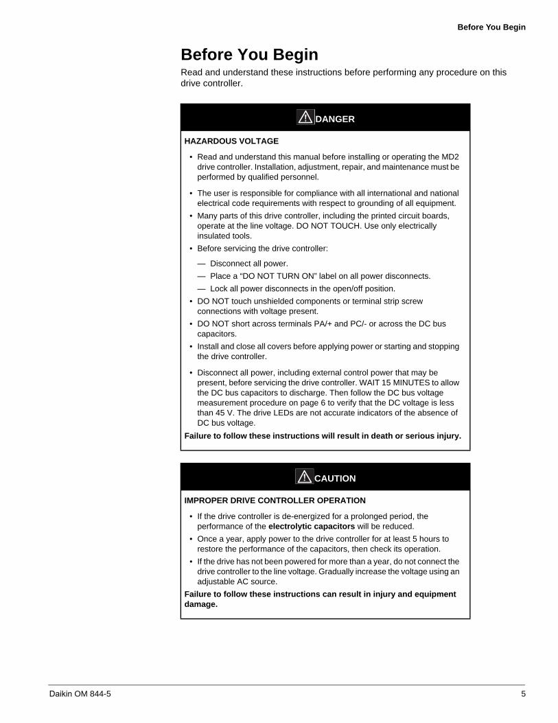
Before You BeginRead and understand these instructions before performing any procedure on this drive controller.
DANGER
HAZARDOUS VOLTAGE
• Read and understand this manual before installing or operating the MD2drive controller. Installation, adjustment, repair, and maintenance must be performed by qualified personnel.
• The user is responsible for compliance with all international and nationalelectrical code requirements with respect to grounding of all equipment.
• Many parts of this drive controller, including the printed circuit boards,operate at the line voltage. DO NOT TOUCH. Use only electricallyinsulated tools.
• Before servicing the drive controller:
— Disconnect all power.
— Place a “DO NOT TURN ON” label on all power disconnects.
— Lock all power disconnects in the open/off position.
• DO NOT touch unshielded components or terminal strip screwconnections with voltage present.
• DO NOT short across terminals PA/+ and PC/- or across the DC buscapacitors.
• Install and close all covers before applying power or starting and stoppingthe drive controller.
• Disconnect all power, including external control power that may bepresent, before servicing the drive controller. WAIT 15 MINUTES to allowthe DC bus capacitors to discharge. Then follow the DC bus voltagemeasurement procedure on page 6 to verify that the DC voltage is lessthan 45 V. The drive LEDs are not accurate indicators of the absence ofDC bus voltage.
Failure to follow these instructions will result in death or serious injury.
CAUTION
IMPROPER DRIVE CONTROLLER OPERATION
• If the drive controller is de-energized for a prolonged period, theperformance of the electrolytic capacitors will be reduced.
• Once a year, apply power to the drive controller for at least 5 hours torestore the performance of the capacitors, then check its operation.
• If the drive has not been powered for more than a year, do not connect the drive controller to the line voltage. Gradually increase the voltage using an adjustable AC source.
Failure to follow these instructions can result in injury and equipment damage.
Daikin OM 844-5 5

Before You Begin
Bus Voltage Measurement Procedure
Before working on the drive controller, turn it off and wait 15 minutes to allow the DC bus to discharge and then measure the DC bus voltage.
The DC bus voltage can exceed 1000 Vdc. Use a properly rated voltage-sensing device when performing this procedure. To measure the DC bus voltage:
1. Disconnect all power and wait 15 minutes to allow the DC bus to discharge.
2. Measure the voltage of the DC bus between the PA/+ and PC/– terminals toensure that the voltage is less than 45 Vdc.
3. If the DC bus capacitors do not discharge completely, contact your local Daikinrepresentative. Do not repair or operate the drive controller.
Figure 1: Capacitor Charging LED
DANGER
AUTOMATIC RESTART ENABLED
• This drive controller can restart under fault conditions.
• Equipment must be shut down, locked out and tagged out to performservicing or maintenance.
Failure to follow this instruction will result in death or serious injury.
DANGER
HAZARDOUS VOLTAGE
Read and understand the precautions in “Before You Begin” on page 5 before performing this procedure.
Failure to follow this instruction will result in death or serious injury.
RUN
PRG
MON
%
Hz
MODELoc
Rem
ENT
RUN STOP
Capacitor Charging LED
6 Daikin OM 844-5

Before You Begin
Initial Start-Up
Before providing power to the VFD, refer to the appropriate unit installation/maintenance manual(s) listed below:
• IM 738 for packaged rooftops with air-cooled condensers (RPS, RFS, and RDT)
• IM 487 for rooftop air handlers (RDS and RAH)
• IM 791 for packaged rooftops with evaporative condensers (RPE and RDE)
• IM 708 for one-piece self-contained units
• IM 709 for modular self-contained units
• IM 843 for Maverick II commercial rooftop units
Perform the following (MicroTech III example) general procedures on the specific unit purchased (yours may differ slightly depending on the unit)
1. Before closing (connecting) the power disconnect switch, open (disconnect) thefollowing unit control circuit switches:
a. Turn system switch S1 to OFF
b. Turn system switch S7 to OFF
2. Confirm duct static pressure sensor SPS1 is connected to the ductwork.
3. Confirm the VFD lugs for the line voltage are tight.
4. Confirm the horsepower (hp) of the drive matches that of the motor.
Before starting the fan and VFD
1. Close the unit disconnect switch. With the control system switch S1 in theOFF position, power should be available only to the control circuit transformer (TI) and the compressor crankcase heaters.
2. Turn the Switch S1 to ON. Power should now be supplied to the control panel.
3. Verify all duct isolation dampers are open. Unit mounted isolation dampers may bemounted in the supply or return sections.
4. Place the unit into the “Fan Only” mode through the keypad menu StandardMenu\System\Ctrl Mode= Fan Only.
5. Confirm the power supply matches the setting of the parameter.
6. Confirm the power supply frequency matches that of the parameter.
7. Confirm the thermal protection level, (or amps), matches that of the motor.
NOTE: All of the above parameters can be quickly found in the AUF Quick menu.
Start the fan and VFD
1. Turn Switch S7 to ON. The controller should enter the “Startup” operating state. Ifthe fan does not run at the completion of the startup mode:
a. Check fuses F1 and F3.
b. Check that the manual motor protectors or circuit breakers have not tripped.
c. Check the optional phase monitor.
2. If the fans are equipped with optional spring isolators, check the fan spring mountadjustment. When the fans are running they should be level.
3. Verify the rotation is correct.
4. Verify the DHL safety is opening at a pressure compatible with duct workingpressure limits.
NOTE: Refer to the unit IMs for additional non-VFD instructions.
Daikin OM 844-5 7
Control Terminals
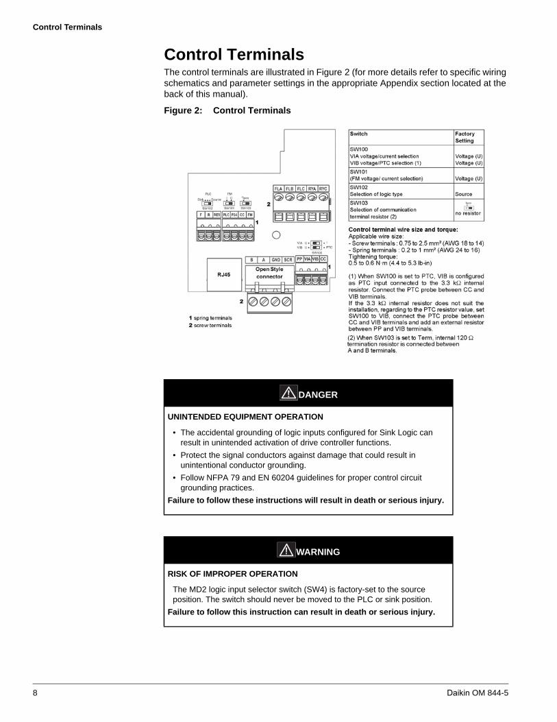
Control TerminalsThe control terminals are illustrated in Figure 2 (for more details refer to specific wiring schematics and parameter settings in the appropriate Appendix section located at the back of this manual).
Figure 2: Control Terminals
DANGER
UNINTENDED EQUIPMENT OPERATION
• The accidental grounding of logic inputs configured for Sink Logic canresult in unintended activation of drive controller functions.
• Protect the signal conductors against damage that could result inunintentional conductor grounding.
• Follow NFPA 79 and EN 60204 guidelines for proper control circuitgrounding practices.
Failure to follow these instructions will result in death or serious injury.
WARNING
RISK OF IMPROPER OPERATION
The MD2 logic input selector switch (SW4) is factory-set to the source position. The switch should never be moved to the PLC or sink position.
Failure to follow this instruction can result in death or serious injury.
8 Daikin OM 844-5

Control Terminals
Table 1: Control Terminal Characteristics
Terminals Function Characteristics
PLCExternal power supply input
input for external power supply for logic inputsMax. permissible voltage: 50 Vac
P24Internal supply
Short-circuit and overload protection:
supply (), maximum current: 200 mA
CC Common 0 V common (2 terminals)
FLA, FLB, FLC
Configurable relay outputs
One relay logic output, one N/C contact, and one N/O contact with common pointMinimum switching capacity: Maximum switching capacity:
• On resistive load: 5 A for 250 Vac or 30 Vdc• On inductive load: 2 A for 250 Vac or 30 Vdc
Max. response time: 7 ms ± 0.5 msElectrical service life: 100,000 operations
RY, RC
One relay logic output, one N/O contactMinimum switching capacity: Maximum switching capacity:
• On resistive load: 5 A for 250 Vac or 30 Vdc• On inductive load: 2 A for 250 Vac or 30 Vdc
Max. response time: 7 ms ± 0.5 ms Electrical service life: 100,000 operations
F
R
RES
Logic inputs
Three programmable logic inputs, compatible with level 1 PLC, IEC 65A-68 standardImpedance: 3.5 kMaximum voltage: 30 VMax. sampling time: 2 ms ± 0.5 msMultiple assignment makes it possible to configure several functions on one input
Positive logic (Source): State 0 if 5 V or logic input not wired, state 1 if 11 V
Negative logic (Sink): State 0 if 16 V or logic input not wired, state 1 if 10 V
FMAnalog output
One switch-configurable voltage or current analog output:
• Voltage analog output 0–10 Vdc, minimum load impedance 470 • Current analog output X–Y mA by programming X and Y from 0 to
20 mA, maximum load impedance: 500
Max. sampling time: 2 ms ± 0.5 msResolution: 10 bitsAccuracy: ± 1% for a temperature variation of 60°CLinearity: ± 0.2%
PPInternal supply available
Short-circuit and overload protection:
One 10.5 Vdc ± 5% supply for the reference potentiometer (1 to 10 k), maximum current: 10 mA
VIAAnalog/logic input
dc +/- 3 Vdc
VIB Analog input • dc
Daikin OM 844-5 9

Switch Settings and Terminal Designations
Switch Settings and Terminal Designations
NOTE: Refer to specific wiring schematics and parameter settings in the appropriate Appendix section located at the back of this manual for HVAC application and switch settings.
NOTE: The logic input switch SW4 is set to the source position. The switch should never be moved to the PLC or sink position.
Figure 3: Switches
DANGER
UNINTENDED EQUIPMENT OPERATION
• The accidental grounding of logic inputs configured for Sink Logic canresult in unintended activation of drive controller functions.
• Protect the signal conductors against damage that could result inunintentional conductor grounding.
• Follow NFPA 79 and EN 60204 guidelines for proper control circuitgrounding practices.
Failure to follow these instructions will result in death or serious injury.
Table 2: Drive Controller Default Terminal Function Assignments
Terminal Function
FLA-FLB-FLC relay De-energized in the event of a fault or when the power supply is disconnected
RY-RC relay Energized when the speed is greater than or equal to low speed ( )
F Forward (2-wire control)
R Preset speed
RES Fault reset
VIA Speed reference 0-10 Vdc
VIB Not assigned
FM Output frequency
SW4
SW4
Selection of logic type
Voltage/current selection for analog I/O (FM and VIA)
SW2 SW3
FM VIA
I (current)I (current)
V (voltage)V (voltage)Source(positive logic)PLCSink(negative logic)
10 Daikin OM 844-5

Integrated Display Terminal
Integrated Display TerminalThe LEDs and keys on the integrated display terminal are illustrated in Figure 4.
NOTE: Display terminal functions described above reflect VFD default settings.
Figure 4: Description of Display Terminal
Table 3: Display Terminal Features
LED/Key Characteristics
1 Display RUN LED• Illuminates when a Run command is applied to the drive controller.• Flashes when there is a speed reference present with a Run
command.
2 Display PRG LED• Illuminates when Programming mode is active.• Flashes in modes.
3 Display MON LED• Illuminates when Monitoring mode is active.• Flashes in Fault History Display mode.
4 Up/Down Keys
Depending on the mode, you can use the arrows to:• Navigate between the menus• Change a value• Change the speed reference when the Up/Down LED (5) is
illuminated
5 Up/Down LEDIlluminates when the navigation arrows are controlling the speed reference.
6 Run LED Illuminates when the Run key is enabled.
7 Run ButtonPressing this button/key when the Run LED is illuminated starts the drive controller.
8 Display 4-digit, 7-segment LED display
9 Units LEDs• The % LED illuminates when the display numeric value is in
percentage.• The Hz LED illuminates when the display numeric value is in Hertz.
10 Loc/Rem LED• Local/Remote mode indicator. Illuminates when Local mode is
selected.
RUN
PRG
MON
%
Hz
MODELoc
Rem
ENT
RUN STOP
1
2
3
4
5
6
7
8
9
10
11
12
13
14
Daikin OM 844-5 11

Integrated Display Terminal
11 Mode Button
Press to select the Mode• Display mode (default)• Adjustment mode• Monitoring mode
Can also be used to go back to the previous menu
12 Loc/Rem Button Switches between Local and Remote modes
13 ENT Button Press to display a parameter’s value or to save a changed value
14 Stop Button
• In Local mode (12), pressing the STOP key decelerates the drive to a stop
• In Remote mode (see table item #10), while the VFD is beingcontrolled by the unit controller, pressing the STOP key will allowthe drive to freewheel stop (drive display will indicate a flashing “ ”)
• If is set to 0 (default setting), pressing the stop key twice willreset the flashing “ ” fault and other resettable faults if the faultcondition has been resolved
DANGER
STOP BUTTON CAN CAUSE MOTOR RESTART
• The Stop Button on this drive controller can reset faults and restart themotor if an active run command is present.
• Disable all run commands and inspect the drive system for the cause ofthe fault before activating a fault reset.
• Disable the panel reset operation ( ) to remove this hazard.
Failure to follow these instructions will result in death or serious injury.
Table 3: Display Terminal Features (continued)
LED/Key Characteristics
12 Daikin OM 844-5

Programming
ProgrammingMode Access
MD2 drive controllers have three modes of operation described in Table 4.
Figure 5 illustrates how to access the modes with the display terminal MODE key.
Figure 5: Mode Access
Parameter Groups
MD2 drive controllers are factory programmed per your HVAC application (refer to specific wiring schematics and parameter settings in the appropriate Appendix section located at the back of this manual for application options and settings).To restore Daikin factory settings, use parameter “” (see Default Setting on page 21).
Table 4: Mode Descriptions
Display mode (default)
• Active when power is applied to the drive controller• Use to display drive controller parameters, alarms, and faults
Adjustment mode • Use to modify drive controller parameters
Monitoring mode • Use to monitor drive controller status
6 0.0 RUNPRGMON
%
Hz f r - fRUNPRGMON
%
Hz
MODE MODE MODE
Display Mode (default)
Adjustment Mode
Monitoring Mode
a.u.f.RUNPRGMON
%
Hz
WARNING
UNINTENDED EQUIPMENT OPERATION
• Any parameter values altered from the VFD control panel will affect theoperation of the drive.
• If parameter “ ” is selected and changed, altered parameters will betransferred into the VFD memory and may affect safe operation of theequipment.
Failure to follow this instruction can result in death, serious injury, or equipment damage.
Table 5: MD2 Parameter Groups
Parameter Type Description
Basic parameters Parameters that need validation before using the drive controller.
Extended Parameters (menu )
Parameters for special settings and applications.
User Parameters (menu )
Subset of Basic and Extended parameters whose values have changed from the VFD default settings.
Quick menu (menu ) Subset of Basic and Extended parameters frequently used.
History Parameters (menu )
Subset of Basic and Extended parameters displaying the five parameters that were last changed, displayed in reverse chronological order.
Daikin OM 844-5 13

Programming
Access to Menus and Parameters
Figure 6: Menu Access
MODE
Basic Parameters
a u H RUNPRGMON
%
Hz
MODE
MODEf - - -RUN
PRGMON
%
Hz
g r u RUNPRGMON
%
Hz
a u 1 RUNPRGMON
%
Hz
a u f RUNPRGMON
%
Hz
KeyMode Key
Up/Down Keys
MODE
a.u.f.RUNPRGMON
%
Hz
f r - fRUNPRGMON
%
Hz
6 0.0 RUNPRGMON
%
Hz
Display Mode
Adjustment Mode
Monitoring Mode
14 Daikin OM 844-5

Programming
Figure 7: Access to Parameters
ENT
NOTE: Press the MODE key to go back to the previous level.For example:· To go from 9.9 to deC· To go from deC to AUF
d E C RUNPRGMON
%
Hz
L L RUNPRGMON
%
Hz
a C C RUNPRGMON
%
Hz
a u 1 RUNPRGMON
%
Hz
KeyEnter Key
Up/Down Keys
ENT
a.u.f.RUNPRGMON
%
Hz
Adjustment Mode
ENT
1 0.0 RUNPRGMON
%
Hz
9.9 RUNPRGMON
%
Hz
1 0.1 RUNPRGMON
%
Hz
ENT
Confirm Value
Daikin OM 844-5 15

AUF Quick Menu
Quick MenuFigure 8 illustrates the parameters accessible from the Quick menu.
Figure 8: Quick Menu Parameters
H e a dRUNPRGMON
%
Hz
a.u.f.RUNPRGMON
%
Hz a u 1 RUNPRGMON
%
Hz
a C C RUNPRGMON
%
Hz
d e C RUNPRGMON
%
Hz
L L RUNPRGMON
%
Hz
u L RUNPRGMON
%
Hz
t H r RUNPRGMON
%
Hz
f n RUNPRGMON
%
Hz
p t RUNPRGMON
%
Hz
e n d RUNPRGMON
%
Hz
v L v RUNPRGMON
%
Hz
v L RUNPRGMON
%
Hz
Top of List
Automatic ramp adaptation
Acceleration ramp times
deceleration ramp times
Minimum motor frequency
Maximum motor frequency
Motor thermal protection
Analog output scaling
Motor control profile
Nominal motor frequency
Nominal motor voltage
End of list
16 Daikin OM 844-5
AUF Quick Menu
Quick Menu Parameters
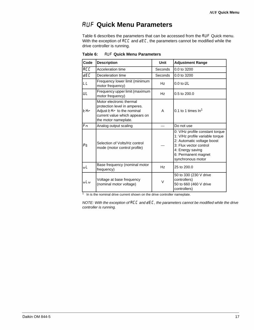
Table 6 describes the parameters that can be accessed from the Quick menu. With the exception of and , the parameters cannot be modified while the drive controller is running.
NOTE: With the exception of and , the parameters cannot be modified while the drive controller is running.
Table 6: Quick Menu Parameters
Code Description Unit Adjustment Range
Acceleration time Seconds 0.0 to 3200
Deceleration time Seconds 0.0 to 3200
Frequency lower limit (minimum motor frequency)
Hz 0.0 to
Frequency upper limit (maximum motor frequency)
Hz 0.5 to 200.0
Motor electronic thermal protection level in amperes. Adjust to the nominal current value which appears on the motor nameplate.
A 0.1 to 1 times In1
1 In is the nominal drive current shown on the drive controller nameplate.
Analog output scaling — Do not use
Selection of Volts/Hz control mode (motor control profile)
—
0: V/Hz profile constant torque1: V/Hz profile variable torque2: Automatic voltage boost3: Flux vector control4: Energy saving6: Permanent magnet synchronous motor
Base frequency (nominal motor frequency)
Hz 25 to 200.0
Voltage at base frequency (nominal motor voltage)
V
50 to 330 (230 V drive controllers)50 to 660 (460 V drive controllers)
Daikin OM 844-5 17

AUF Quick Menu
Setting the Acceleration/DecelerationRamp Times
Acceleration/deceleration ramp adaptation. Automatically adjusts the acceleration/deceleration ramp times to match the inertia of the load.
Programs the time it takes for the drive controller output frequency to go from 0 Hz to the maximum frequency (parameter ).
Programs the time it takes for drive controller output frequency to go from maximum frequency (parameter ), to 0 Hz.
Refer to specific wiring schematics and parameter settings in the appropriate Appendix section located at the back of this manual for application options and settings.
Acceleration/Deceleration Ramp Adaptation
• = 0: Function is disabled.
• = 1: Automatically adjusts the acceleration and deceleration ramp times from1/8–8 times the value set in the or parameters, depending on the currentrating of the drive controller.
• = 2: Do not use.
Table 7: Setting Ramp Time Parameters
Parameter Name Range
Automatic Acceleration/ Deceleration Ramp Adaptation
0: Disabled1: Automatic2: Automatic acceleration only(Do not use)
Acceleration Time 1 0.0 to 3200 s
Deceleration Time 1 0.0 to 3200 s
Figure 9: Automatic Ramp Adaptation
0
Outputfrequency (Hz)
FH
Outputfrequency (Hz)
FH
Acceleration Time
Deceleration Time
Acceleration Time
Deceleration Time
Time(seconds)
Time(seconds)
When load is small ... When load is large ...
0
shorten acceleration/deceleration time. lengthen acceleration/deceleration time.
18 Daikin OM 844-5

AUF Quick Menu
Manually Setting Acceleration/Deceleration Ramp Times
During startup, confirm parameters and match the parameters in the appropriate Appendix section located at the back of this manual for specific HVAC application.
Setting the Macro Function
Sets the drive controller to one of four macro configurations. The macro configuration selection automatically determines the settings of the following parameters: , , – , and .
NOTE: The current setting of this parameter is shown on the left side of the display. The number 0 is always displayed on the right. For example, indicates that the freewheel stop setting is enabled.
Setting the Mode of Operation
In Remote mode, start and stop commands and the frequency are determined by the settings of (Command mode) and (Frequency Setting mode).
When Local mode is selected with the key, start/stop commands and frequency settings can only be made from the display terminal. The Local LED illuminates while Local mode is selected. See page 11 for Local/Remote key operation and Local LED.
When service is complete, return the VFD to the remote mode.
Figure 10: Manually Setting the Acceleration/Deceleration Ramp Times
Table 8: Parameter
Parameter Name Range
Macro Function
0: Disabled1: Freewheel stop2: 3-wire operation3: + - speed from logic input(s)4: 4–20 mA current input operation
WARNING
UNINTENDED EQUIPMENT OPERATION
• Modifying or changing parameters whose function is not described in thismanual will affect drive controller operation. Some register changes willtake effect as soon as they are entered.
• Do not modify or change parameters whose function is not described inthis instruction bulletin.
Failure to follow this instruction can result in death or serious injury.
Output frequency (Hz)
Time (seconds)
AUI = 0 (Manual)FH
A CC dE C
0
LOCREM
Daikin OM 844-5 19

AUF Quick Menu
Command Mode Selection
Specifies which command source has priority in issuing Start and stop commands.
NOTE: You must stop the drive controller before changing the setting of .
• = 0: Start and stop commands via the logic inputs on the control terminalboard.
• = 1: The and keys on the display terminal start and stop the drive controller.
• = 2: The serial link sends start and stop commands to the drive controller.
Some functions, when assigned to an input terminal, are commanded by the input terminal even if is set to 1 (display terminal).
Priority commands via a serial link can take precedence over the setting of .
Frequency Mode Selection
Specifies which input device has priority in issuing a speed reference command.
NOTE: You must stop the drive controller before changing the setting of . Preset speed operation is allowed with all settings of .
• = 1: Speed Reference command via analog input terminal VIA (0-10 Vdc or4-20 mAdc).
• = 2: Speed Reference command via analog input terminal VIB (0-10 Vdc) -not used with Daikin controls.
• = 3: Speed reference via the and arrow keys on the display terminal or the optional remote keypad.
• = 4: Speed reference via serial communication link - not used with Daikincontrols.
• = 5: Speed reference from +/- speed from logic input(s)
Table 9: Parameter
Parameter Name Range
Command Mode Selection
0: Terminal board1: Display terminal2: Serial communication
Table 10: Parameter
Parameter Name Range
Frequency Mode Selection
1: VIA2: VIB (not used with Daikin controls)3: Display terminal4: Serial communication (not used with Daikin controls)5: +/- speed from logic input(s)
20 Daikin OM 844-5

AUF Quick Menu
Default Setting
This parameter provides a variety of functions to reset, restore and save parameter settings.
* You may replace Daikin parameters if this is used.
NOTE: You must stop the drive controller before changing the setting of .
NOTE: The following parameters are not affected by settings 1, 2, and 3: , , , , and .
NOTE: The setting display of this parameter contains two numbers. The left-most number displays the last operation performed. The right-most number indicates the pending operation and should be adjusted for the action desired.
Forward/Reverse Run Selection
Programs the direction of motor rotation when starting the drive from the keypad display.
NOTE: For more information, contact your Daikin representative.
WARNING
UNINTENDED EQUIPMENT OPERATION
• Drive controller default parameter settings will be substituted for thepresent settings when value 3 (standard default settings) of theparameter is selected.
• Drive controller default parameter settings may not be compatible with theapplication.
• Contact Daikin product support before initiating standard defaultsettings.
Failure to follow these instructions can result in death, serious injury, or equipment damage
Table 11: Parameter
Parameter Name Range
Default Setting
0: 1: 50 Hz default2: 60 Hz default3: Standard default settings (Initialization)4: Clear the fault record5: Clear the cumulative operation time6: Initialize the type information7: Save the user-defined parameters (do not use)*8:Recalls your Daikin defined parameters 9: Clear the cumulative fan operation time
Table 12: Parameter
Parameter Name Range
Forward/Reverse Run Selection
0: Forward run1: Reverse run (do not use)2: Forward run with forward/ reverse switching (do not use)3: Reverse run with forward/reverse switching (do not use)
Daikin OM 844-5 21

AUF Quick Menu
Maximum Frequency
Programs the maximum output frequency of the drive controller. This value is used as the maximum frequency reference for the acceleration and deceleration ramps.
NOTE: You must stop the drive controller before changing the setting of .
NOTE: can not be adjusted during operation
NOTE: value can not exceed value.
CAUTION
UNINTENDED EQUIPMENT OPERATION
• Do not use above 60Hz.
Failure to follow this instruction can result in equipment damage.
Table 13: Parameter
Parameter Name Range
Maximum Frequency
30–200 (Hz)
Figure 11: Maximum Frequency
0
Output frequency (Hz)
80 Hz
60 Hz
100 % Frequency setting signal (%)
When FH = 80 Hz
When FH = 60 Hz
22 Daikin OM 844-5

AUF Quick Menu
High Speed and Low Speed
Programs the high speed.
Programs the low speed.
Nominal Motor Frequency and Voltage Settings
Use these parameters to set the nominal motor frequency ( ) and voltage settings ( ) to the motor nameplate values.
Table 14: Parameters and
Parameter Name Range
High Speed 0.5– (Hz)
Low Speed 0.0– (Hz)
Figure 12: High speed and low speed
Table 15: Parameters and
Parameter Name Range
Nominal Motor Frequency
25.0–200.0 Hz
Voltage Setting50.0–330 V: 200 V Class50.0–660 V: 400 V Class
Figure 13: Nominal motor frequency and voltage settings
Output frequency (Hz) Output frequency (Hz)
uL
High Speed Low Speed
Speed Reference signal Speed Reference signal0 100 % 0 100 %
LL
,
Output frequency
Out
put v
olta
ge (V
)
uLu
uL0
Daikin OM 844-5 23

AUF Quick Menu
V/Hz Control Mode Selection
Use this parameter to set the V/Hz control mode.
Voltage Boost (Energy Recovery Application Only)
Use this parameter to increases the voltage boost rate. This function is useful for applications where the torque is not adequate at low speeds.
V/Hz Control Mode ( ) must be set to 0 (V/Hz constant) or 1 (variable torque) to use this function.
The optimum setting for Voltage Boost depends on the drive controller capacity. Increasing Voltage Boost too much can cause the drive controller to fault on an overcurrent at start up.
Table 16: Parameter
Parameter Name Range
V/Hz Control Mode Selection
0: V/Hz constant (do not use) 1: Variable torque2: Automatic voltage boost control 3: Vector control (do not use)4: Energy saving (do not use)5: No assignment (do not use)6: PM motor control (do not use)
Table 17: Parameter
Parameter Name Range
Voltage Boost 0.0–30.0%
Figure 14: Voltage Boost
Output frequency (Hz)
Out
put v
olta
ge(V
)/(%
)
uLu
uL0
ub
24 Daikin OM 844-5

AUF Quick Menu
Electronic Motor Overload Protection
Motor rated current value (FLA)
Electronic motor overload characteristics
Electronic motor overload memory
These parameters must be set to match the rating and characteristics of the motor (refer to the motor nameplate, full load amps).
Table 18: Electronic Thermal Protection Parameter Settings
Parameter Name Adjustment Range
Motor Electronic Thermal Protection
0.1–1.0 In.1 Set to the rated current indicated on the motor nameplate.
1 “In.” corresponds to the drive rated current indicated on the drive controller nameplate.
Electronic Thermal Protection Characteristic
Setting ValueOverload Protection
Overload Stall
0Self
Cooled Motor
Enabled Disabled
1 Enabled Enabled
2 Disabled Disabled
3 Disabled Enabled
4
(do not use)
Forced Cooled Motor
Enabled Disabled
5
(do not use)Enabled Enabled
6
(do not use)Disabled Disabled
7
(do not use)Disabled Enabled
Electronic Motor Thermal State Memory
0: Disabled
1: Enabled
CAUTION
MOTOR OVERHEATING
This drive controller does not provide direct thermal protection for the motor. Use of a thermal sensor in the motor may be required for protection at all speeds and load conditions. Consult the motor manufacturer for thermal capability of the motor when operated over the desired speed range.
Failure to follow this instruction can result in injury or equipment damage.
Daikin OM 844-5 25

AUF Quick Menu
Setting , and
Use electronic thermal protection characteristics ( ) to enable or disable the motor overload fault function ( ) and the overload stall function.
While the drive controller overload fault ( , see page 25) is always enabled, motor overload fault ( ) can be selected using parameter .
Overload stall is used with variable torque loads such as fans, pumps, and blowers, in which the load current decreases as the operating speed decreases. When the drive controller detects an overload, overload stall automatically lowers the output frequency before the motor overload fault, , is activated. This function maintains the motor at frequencies that allow the load current to remain balanced so that the drive controller can continue operation without tripping.
NOTE: Do not use overload stall with constant torque loads such as conveyor belts in which load current is fixed with no relation to speed.
Self Cooled Motors
To set electronic thermal protection characteristics, , for a self-cooled motor, refer to Table 18.
If the capacity of the motor is smaller than the capacity of the drive controller, or the rated current of the motor is smaller than the rated current of the drive controller, set the electronic thermal protection level, , to the motor's nominal rated current value.
Motor Electric Thermal Protection Retention,
The setting of this parameter determines whether electric thermal calculation values are retained when power is removed. Enabling the parameter ( = 1) causes the electric thermal calculation values to be retained when power is removed.
NOTE: For installations to meet Article 430 of the National Electric Code, parameter F632 must be set to 1.
Figure 15: Motor Electronic Thermal Protection: Self-cooled motor
Output current factor(%)/(A)
Output frequency (Hz)30 Hz0
x 1.0
x 0.55
tHr
tHr
26 Daikin OM 844-5

AUF Quick Menu
Input Signal Selection
VIA terminal function selection
This parameter allows you to select an analog or digital input for the VIA terminal.
When using the VIA terminal as a digital input terminal, set the VIA slide switch to the V position. For switch location see Figure 2.
Terminal Function Selection
Modifying Input Terminal Functions
The functions selected with parameters are always active.
Table 19: Parameter
Parameter Name Range
Analog/Digital Input Function Selection (VIA Terminal)
0: Analog input1: Do not use (sinking input assignment)2: Digital (sourcing) input
DANGER
UNINTENDED EQUIPMENT OPERATION
• The accidental grounding of logic inputs configured for Sink Logic canresult in unintended activation of drive controller functions.
• Protect the signal conductors against damage that could result inunintentional conductor grounding.
• Follow NFPA 79 and EN 60204 guidelines for proper control circuitgrounding practices.
Failure to follow these instructions will result in death or serious injury.
Table 20: Parameters , , , , and
Terminal Symbol
Parameter Name Range
—
Always-Active Function (the control input function assigned to this parameter will always be active). 0–71
(refer to appropriate Appendix for specific parameter settings)
F Logic Input
R Logic Input
RES Logic Input
VIA Input Terminal
Daikin OM 844-5 27

AUF Quick Menu
Modifying Output Terminal Functions
Output terminal selection 1A (RY-RC)
Jump Frequency (Jumping Resonant Frequencies)
Jump Frequency 1
Jumping Width 1
Jump Frequency 2
Jumping Width 2
Jump Frequency 3
Jumping Width 3
Resonance due to the natural frequency of the mechanical system can be avoided by jumping the resonant frequency during operation.
Figure 16: Application Example
Table 21: Assigning One Function to an Output Terminal
Terminal Symbol
Parameter Name Range
RY-RC Output Terminal Selection 1A
0–255(refer to appropriate Appendix for specific parameter settings)
Figure 17: Jump Frequency Timing Diagram
RY
RC
RY
Function of RY-RC:Can be set using parameter
Jumping width 1 (F271)
Jumping width 2 (F273)
Jumping width 3 (F275)Jump frequency 3 (F274)
Jump frequency 1 (F270)
Jump frequency 2 (F272)
Output command frequency(Hz)
Frequency setting signal0
28 Daikin OM 844-5

AUF Quick Menu
NOTE: The jump frequency plus jump width may not overlap another jump frequency plus jump width.
NOTE: During acceleration or deceleration, the jumping function is disabled for the operation frequency.
Switching Frequency
Switching Frequency
Random Mode
The parameter allows the audible noise from the motor to be changed by altering the switching frequency.
In addition, the parameter reduces the electromagnetic noise generated by the drive controller. Decrease the switching frequency to reduce electromagnetic noise.
NOTE: Although the electromagnetic noise level is reduced when decreasing switching frequency, the acoustic noise of the motor is increased.
The parameter (random mode) reduces motor electromagnetic and acoustic noise by changing the pattern of the switching frequency.
Table 22: Jump Frequency Parameter Setting
Parameter Name Range
Jump Frequency 1 0.0– (Hz)
Jump Width 1 0.0–30.0 (Hz)
Jump Frequency 2 0.0– (Hz)
Jump Width 2 0.0–30.0 (Hz)
Jump Frequency 3 0.0– (Hz)
Jump Width 3 0.0–30.0 (Hz)
Table 23: Parameters ,
Parameter Name Range
Switching Frequency 6.0–16.0 (kHz)
Random Mode0: Disabled1: Enabled
Daikin OM 844-5 29

AUF Quick Menu
Auto Restart
Select the number of restarts
This parameter resets the drive controller automatically if it is in an alarm state.
DANGER
AUTOMATIC RESTART ENABLED
• This drive controller can restart under fault conditions.
• Equipment must be shut down, locked out and tagged out to performservicing or maintenance.
Failure to follow these instructions will result in death or serious injury.
Table 24: Parameter
Parameter Name Range
Number of Restarts0: Disabled1–10: 1 to 10 restarts
Table 25: Causes of Tripping and Corresponding Restart Processes
Cause of Tripping
Restart Process Canceling Conditions
Momentary power failure
Overcurrent
Overvoltage
Overload
Overheating
Up to 10 restarts in succession
1st restart: 1 second after tripping
2nd restart: 2 seconds after tripping
3rd restart: 3 seconds after tripping
10th restart: About 10 seconds after tripping
Auto restart is possible only after the following faults: momentary power failure, overcurrent, overvoltage, or overload.
The restart function will be canceled if restarting is not successful within the specified number of times.
30 Daikin OM 844-5

AUF Quick Menu
Restart is disabled when the faults or errors listed in Table 26 occur.
When using Auto Restart, observe the following:
• By default, protective operation detection relay signals (FLA-FLB-FLC terminalsignals) are not sent during an auto restart process. To allow a signal to be sent tothe protective operation detection relay (FLA-FLB-FLC terminals) during an autorestart process, assign value 36 or 37 to parameter .
• A calculated cooling time is provided for overload tripping ( , , ). In thiscase, the auto restart function operates after the calculated cooling time and therestart time.
Table 26: Faults Which Cannot Be Automatically Reset
Motor overcurrent at start up
Overcurrent on load side at start up
Output phase loss
External thermal fault
Overtorque fault
External fault stop
Low-current operation fault
Undervoltage fault (main circuit)
Ground fault
Input phase loss
Drive controller error
Main unit RAM fault
Main unit ROM fault
CPU fault
Remote control error
Current detector fault
Control circuit board format error
EEPROM fault 1
EEPROM fault 2
EEPROM fault 3
Auto-tuning error
VIA input detection error
Main unit CPU communication error
Excessive voltage boost
CPU fault 2
CAUTION
MOTOR OVERHEATING
• Repeated reset of the thermal overload can result in thermal stress to themotor.
• When faults occur, promptly inspect the motor and driven equipment forproblems such as locked shaft and mechanical overload before restarting. Also check the power supplied to the motor for abnormal conditions suchas phase loss and phase imbalance.
Failure to follow these instructions can result in equipment damage.
Daikin OM 844-5 31
AUF Quick Menu
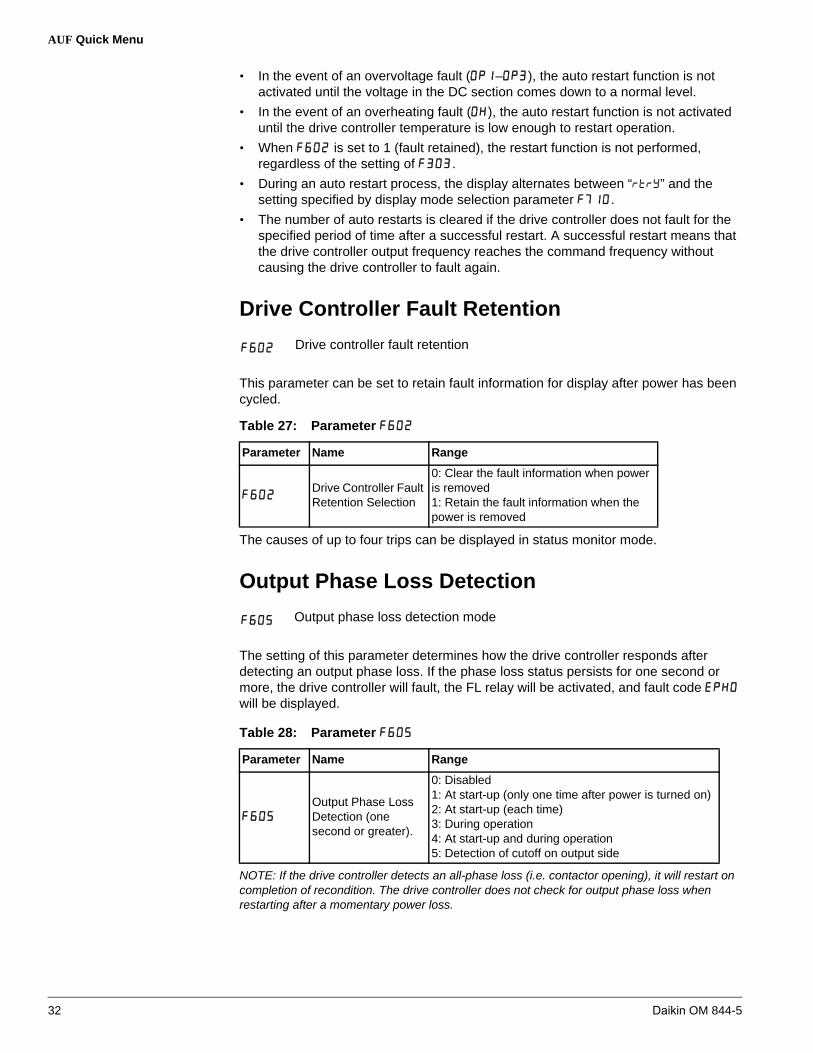
• In the event of an overvoltage fault (–), the auto restart function is notactivated until the voltage in the DC section comes down to a normal level.
• In the event of an overheating fault ( ), the auto restart function is not activateduntil the drive controller temperature is low enough to restart operation.
• When is set to 1 (fault retained), the restart function is not performed,regardless of the setting of .
• During an auto restart process, the display alternates between “” and thesetting specified by display mode selection parameter .
• The number of auto restarts is cleared if the drive controller does not fault for thespecified period of time after a successful restart. A successful restart means thatthe drive controller output frequency reaches the command frequency withoutcausing the drive controller to fault again.
Drive Controller Fault Retention
Drive controller fault retention
This parameter can be set to retain fault information for display after power has been cycled.
The causes of up to four trips can be displayed in status monitor mode.
Output Phase Loss Detection
Output phase loss detection mode
The setting of this parameter determines how the drive controller responds after detecting an output phase loss. If the phase loss status persists for one second or more, the drive controller will fault, the FL relay will be activated, and fault code will be displayed.
NOTE: If the drive controller detects an all-phase loss (i.e. contactor opening), it will restart on completion of recondition. The drive controller does not check for output phase loss when restarting after a momentary power loss.
Table 27: Parameter
Parameter Name Range
Drive Controller Fault Retention Selection
0: Clear the fault information when power is removed1: Retain the fault information when the power is removed
Table 28: Parameter
Parameter Name Range
Output Phase Loss Detection (one second or greater).
0: Disabled1: At start-up (only one time after power is turned on)2: At start-up (each time)3: During operation4: At start-up and during operation5: Detection of cutoff on output side
32 Daikin OM 844-5

AUF Quick Menu
Input Phase Loss Detection
Input phase loss detection mode selection
Setting this parameter to 1 (default) enables Input Phase Loss Detection. During a complete input phase loss event the drive controller will fault (code ) and the relay will be activated.
NOTE: The drive controller may not fault on all input phase imbalance conditions.
Input phase loss nuisance tripping on low source impedance power systems may indicate the need to install an AC input line reactor.
Setting to 0 (input phase loss detection disabled) may result in damage to the drive controller if operation is continued under a heavy load during an input phase loss.
Avoiding Overvoltage Tripping
Overvoltage limit operation
Overvoltage stall protection level
Use these parameters to keep the output frequency constant, or to increase it to prevent overvoltage tripping should the voltage in the DC section rise during deceleration or varying speed operation. The deceleration time during overvoltage limit operation may increase above the designated time. Overvoltage stall protection level sets the percentage of the nominal DC bus level where the drive will modify the output frequency to prevent an Overvoltage fault.
Table 29: Parameter
Parameter Name Range
Input Phase Loss Detection0: Disabled1: Enabled
Figure 18: Overvoltage Limit Operation Level
CAUTION
MOTOR OVERHEATING
• Repetitive braking can cause motor overheating and damage if the QuickDeceleration or Dynamic Quick Deceleration features are active.
• Use of a thermal sensor in the motor is recommended to protect the motor during repetitive braking.
Failure to follow these instructions can result in injury or equipment damage.
DC Voltage
OutputFrequency
F626 : Over-voltage stall protection level
Daikin OM 844-5 33

AUF Quick Menu
* Daikin setting = 140%. If power transients are more common than normal, increase toward150%.
If is set to 2 (quick deceleration), the drive controller will increase the voltage to the motor (over-excitation control) to increase the amount of energy consumed by the motor when the voltage reaches the overvoltage protection level. The motor can therefore be decelerated more quickly than with normal deceleration.
If is set to 3 (dynamic quick deceleration), the drive controller will increase the voltage to the motor (over-excitation control) to increase the amount of energy consumed by the motor as soon as the motor begins to slow down. The motor can therefore be decelerated even more quickly than with quick deceleration.
Undervoltage Fault
Undervoltage fault/alarm selection
The setting of this parameter determines how the drive controller responds when it detects an undervoltage. The fault code displayed is .
Table 30: Parameters ,
Parameter Name Range
Overvoltage Limit Operation
0: Enabled1: Disabled2: Enabled (quick deceleration - do not use)3: Enabled (dynamic quick deceleration - do not use)
Overvoltage Stall Protection Level
100–150%*
Table 31: Parameter
Parameter Name Range
Undervoltage Fault/Alarm Selection
0: Alarm only (input voltage level below 60%)The drive controller stops but does not fault (the FL relay is not activated).
1: Fault (detection level below 60%)The drive controller stops and faults when the input voltage is less than 60% of it's rating.
2: Alarm only (input voltage level below 50%, input reactor needed)The drive controller stops but does not fault when the input voltage is less than 50% of it's rating. A line reactor must be used with this setting.
34 Daikin OM 844-5

AUF Quick Menu
Changing the Display Parameter
Display selection
When power is applied to the drive controller, it is in display mode. The display terminal shows operation frequency as the default setting.
Table 32: Parameter
Parameter Name Range
Display Selection
0: Operation frequency (Hz/free unit/step)1: Frequency command (Hz/free unit/step)2: Output current (%/A)3: Drive controller rated current (A)4: Drive controller load factor (%)5: Output power6: Frequency command after PID control (Hz/free unit/step)7: Optional item specified from an external control unit8: Output speed of fan motor9: Communication counter10: Normal state communication counter
Daikin OM 844-5 35

Troubleshooting Fault and Alarm Codes
Troubleshooting Fault and Alarm CodesWhen an alarm or fault occurs, use Tables 33 and 34 to diagnose and resolve the problem.
If the problem cannot be resolved by any of the actions described in the tables, refer to the programming guide or contact your Daikin representative.
Drive Controller Fault Conditions
Table 33: Fault Codes
Error Code
Failure Code
Problem Possible Causes Remedies
0001
0025
Overcurrent during acceleration
Transistor overcurrent
• The acceleration time is too short.
• The V/Hz setting isimproper.
• A restart signal is input to the rotating motor after amomentary stop, etc.
• A special motor (e.g.motor with a smallimpedance) is used.
• Possible ground fault.
• Increase the accelerationtime, .
• Check the V/Hzparameter.
• Use (auto-restart)and (ride-throughcontrol).
• Adjust the switchingfrequency .
• Set the switchingfrequency control modeselection parameter to 1 or 3 (switchingfrequency decreasedautomatically).
0002
0026
Overcurrent during deceleration
Transistor overcurrent
• The deceleration time is too short.
• Possible ground fault.
• Increase the decelerationtime .
• Set the switchingfrequency control modeselection parameter to 1 or 3 (switchingfrequency decreasedautomatically).
0003
0027
Overcurrent during constant speed operation
Transistor overcurrent
• The load fluctuatesabruptly.
• Mechanical blockage
• Reduce the loadfluctuation.
• Check the load (operatedmachine).
• Set the switchingfrequency control modeselection parameter to 1 or 3 (switchingfrequency decreasedautomatically).
0025
0026
0027
Ground fault
Motor overcurrent at start-up
(for 15 and 20 hp models only)
• A current leaked from anoutput cable or the motor to ground.
• A main circuit elementsis defective.
• Contact your Daikin representative.
• Check the cablesconnecting the drivecontroller to the motor,and check the motorinsulation.
• Reduce the switchingfrequency.
• Connect output filters inseries with the motor.
36 Daikin OM 844-5

Troubleshooting Fault and Alarm Codes
0004
Overcurrent (an overcurrent on the load side at start-up)
• The insulation of theoutput main circuit ormotor is defective.
• Motor impedance is toolow
• Current is leaked from an output cable or the motor to ground.
• Check the cables andwires for defectiveinsulation.
• Check cables,connectors, and so on forground faults.
0005Motor overcurrent at start-up
• A main circuit elementsis defective.
• Possible ground fault
• Check the cablesconnecting the drivecontroller to the motor,and check the motorinsulation.
• Reduce the switchingfrequency.
• Connect output filters inseries with the motor.
• Contact your Daikin representative.
* 0008 Input phase loss
• Input phase loss, blownfuse
• Three-phase drivecontroller used on asingle phase line supply
• Input phase imbalance• Transient phase fault
• Check the main circuitinput line for phase loss.
• Enable (inputphase loss detection).
* 0009Output phase loss
• Loss of phase at drivecontroller output
• Downstream contactoropen
• Motor not connected• Instability in the motor
current• Drive controller
oversized for motor
• Check the main circuitoutput line, motor, etc. forphase loss.
• Enable (outputphase loss detection).
000AOvervoltage during acceleration
• Line voltage too high• Line supply transients• A restart signal is input to
the rotating motor after amomentary stop, etc.
• There is possibility ofoutput phase loss.
• Check the line voltage.Compare with the drivecontroller nameplaterating.
• Reset the drive controller.• Install a line reactor• Use (auto-restart)
and (ride-throughcontrol).
• Check the main circuitoutput line, motor, etc. forphase loss.
000BOvervoltage during deceleration
• The deceleration time is too short.(regenerative energy istoo large.)
• (overvoltage limitoperation) is off.
• The input voltagefluctuates abnormally:
• Overhauling load• There is possibility of
output phase loss.
• Increase the decelerationtime .
• Enable (overvoltage limitoperation).
• Check the main circuitoutput line, motor, etc. forphase loss.
Table 33: Fault Codes (continued)
Error Code
Failure Code
Problem Possible Causes Remedies
Daikin OM 844-5 37

Troubleshooting Fault and Alarm Codes
000COvervoltage during constant-speed operation
• The input voltagefluctuates abnormally.
• The motor is in aregenerative statebecause the load causes the motor to run at afrequency higher thanthe drive controlleroutput frequency.
• There is possibility ofoutput phase loss.
• Check the main circuitoutput line, motor, etc. forphase loss.
000DDrive controller overload
• The acceleration time is too short.
• The DC braking level istoo large.
• The V/Hz setting isimproper.
• A restart signal is input to the rotating motor after amomentary stop, etc.
• The load is too large.
• Increase the accelerationtime .
• Reduce the DC brakingamount and the DC braking time .
• Check the V/Hzparameter setting.
• Use (auto-restart)and (ride-throughcontrol).
• Use an drive controllerwith a larger rating.
000E Motor overload
• The V/Hz setting isimproper.
• The motor is locked.• Low-speed operation is
performed continuously.• An excessive load is
applied to the motorduring operation.
• Check the V/Hzparameter setting.
• Check the load (operatedmachine).
• Adjust to theoverload that the motorcan withstand duringoperation in a low speedrange.
*0020
Over-torque fault
• Over-torque duringoperation.
• Enable (over-torque fault selection).
• Check system error.
0010Drive controller over temperature
• The cooling fan does notrotate.
• The ambienttemperature is too high.
• The vent is blocked.• A heat generating device
is installed close to thedrive controller.
• The thermistor in the unit is broken.
• Restart the operation byresetting the drivecontroller after it hascooled down.
• The fan requiresreplacement if it does notrotate during operation.
• Ensure sufficient spacearound the drivecontroller.
• Do not place any heatgenerating device nearthe drive controller.
• Contact your Daikinrepresentative.
OH2
002EExternal thermal fault
• External thermal fault.• External PTC probe
fault.
• Check the externalthermal input.
• Check the PTC in themotor.
0011 Emergency stop
• During automaticoperation or remoteoperation, a stopcommand is enteredfrom the operation panelor a remote input device.
• Reset the drive controller.
Table 33: Fault Codes (continued)
Error Code
Failure Code
Problem Possible Causes Remedies
38 Daikin OM 844-5

Troubleshooting Fault and Alarm Codes
0012 EEPROM fault 1 • Data writing error.
• Turn off the drive controller, then turn it again. If it does not recover from the error, contact your Daikin representative.
0013 EEPROM fault 2
• Power supply is cut offduring operationand data writing isaborted.
• Turn the power offtemporarily and turn itback on, and then try operation again.
0014 EEPROM fault 3• A data reading error
occurred.
• Turn off the drive controller, then turn it again. If it does not recover from the error, contact your Daikin representative.
0015Main unit RAM fault
• The control RAM isdefective.
• Contact your Daikin representative.
0016Main unit ROM fault
• The control ROM isdefective.
• Contact your Daikin representative.
0017 CPU fault 1• The control CPU is
defective.• Contact your Daikin
representative.
*0018
Communication error
• An error arises duringserial communication.
• Check the remote controldevice, cables, etc.
001ACurrent detector fault
• The current detector isdefective.
• Contact your Daikin representative.
001B Network error • The error has occurred
during Networkcommunication.
• Check the Networkdevice and wiring.
* 001DLow-current operation fault
• The output currentdecreased to a low-current detection levelduring operation.
• Enable (low-current detection).
• Check the suitabledetection level for thesystem ( , ).
* 001E
Undervoltage fault
(main circuit)
• The input voltage (in themain circuit) is too low.
• Check the input voltage.• Enable
(undervoltage faultselection).
• To cope with amomentary stop due toundervoltage, enable (ride-throughcontrol) and (auto-restart).
0022 Ground fault• A ground fault occurs in
the output cable or themotor.
• Check the cable and themotor for ground faults.
* 0054Auto-tuning error
• Check the motor parameter to .• The motor with the capacity of 2 classes or less than
the drive controller is used.• The output cable is improperly sized.• The motor is rotating.• The drive controller is used for loads other than those of
three-phase induction motors.
0029Drive controller type error
• Circuit board is changed. (or main circuit/drivecircuit board)
• Contact your Daikin representative.
Table 33: Fault Codes (continued)
Error Code
Failure Code
Problem Possible Causes Remedies
Daikin OM 844-5 39

Troubleshooting Fault and Alarm Codes
* You can select a trip ON/OFF by parameters.
Drive Controller Alarm Conditions
Alarms do not cause the drive controller to fault.
* 0032Break in analog signal cable
• The signal input via VIAis below the analogsignal detection level setwith .
• Check the cables forbreaks. And check thesetting of input signal orsetting value of .
0033CPU communication error
• A communications erroroccurs between controlCPUs.
• Contact your Daikin representative.
0034Excessive voltage boost
• The voltage boostparameter is settoo high.
• Impedance of the motoris too low
• Decrease the setting ofthe voltage boostparameter .
0035 CPU fault 2• The control CPU is
defective.• Contact your Daikin
representative.
002FStep-out (for PM motor only)
• The motor shaft islocked.
• One output phase isopen.
• An impact load isapplied.
• Unlock the motor shaft.• Check the interconnect
cables between the drivecontroller and the motor.
Table 34: Alarm Codes
Error Code
Problem Possible Causes Remedies
ST terminal OFF
• The ST-CC circuit is opened. • Close the ST-CC circuit.
Undervoltage in main circuit
• The supply voltage between R, S and T is under voltage.
• Measure the main circuit supplyvoltage.If the voltage is at a normal level, the drive controller requiresrepairing.
Restart in process
• The drive controller is in theprocess of restart.
• A momentary stop occurred.
• The drive controller is operatingnormally if it restarts afterseveral tens of seconds.
Frequency point setting error alarm
• The frequency setting signalsat points 1 and 2 are set tooclose to each other.
• Set the frequency setting signals at points 1 and 2 apart fromeach other.
Clear command acceptable
• This message is displayedwhen pressing the STOP keywhile an error code isdisplayed.
• Press the STOP key again toclear the fault.
Emergency stop command acceptable
• The operation panel is used tostop the operation in automatic control or remote control mode.
• Press the STOP key for anemergency stop.To cancel the emergency stop,press any other key.
Table 33: Fault Codes (continued)
Error Code
Failure Code
Problem Possible Causes Remedies
40 Daikin OM 844-5

Troubleshooting Fault and Alarm Codes
/
Setting error alarm /
An error code and data are displayed alternately twice each.
• An error is found in a settingwhen data is reading or writing.
• Check whether the setting ismade correctly.
/
Display of first/last data items
• The first and last data item inthe data group is displayed.
• Press MODE key to exit the datagroup.
DC braking • DC braking in process• The message goes off in several
tens of seconds if no problemoccurs.
Flowing out of excess number of digits
• The number of digits such asfrequencies is more than 4.(The upper digits have apriority.)
• Lower the frequency free unitmagnification
Momentary power failure slowdown stop prohibition function activated.
• The slowdown stop prohibitionfunction set with (momentary power failure ride-through operation) is activated.
• To restart operation, reset thedrive controller or input anoperation signal again.
Auto-stop because of continuous operation at the lower-limit frequency
• The automatic stop functionselected with wasactivated.
• To deactivate the automatic stopfunction, increase the frequencycommand above the lower-limitfrequency ( ) + 0.2 Hz or turnoff the operation command.
Parameters in the process of initialization
• Parameters are beinginitialized to default values.
• Normal if the messagedisappears after a while (several seconds to several tens ofseconds).
Operation panel key fault
• The RUN or STOP key is helddown for more than 20seconds.
• The RUN or STOP key isfaulty.
• Check the operation panel.
Auto-tuning • Auto-tuning in process• Normal if it the message
disappears after a few seconds.
Integral input power
• Integral input power is morethan 999.99 kWh.
• Press and hold down the key for3 seconds or more when poweris off or when the input terminalfunction CKWH is turned on ordisplayed.
Integral output power
• Integral output power is morethan 999.99 kWh.
• Press and hold down the key for3 seconds or more when poweris off or when the input terminalfunction CKWH is turned on ordisplayed.
Table 34: Alarm Codes (continued)
Error Code
Problem Possible Causes Remedies
Daikin OM 844-5 41
Troubleshooting Fault and Alarm Codes
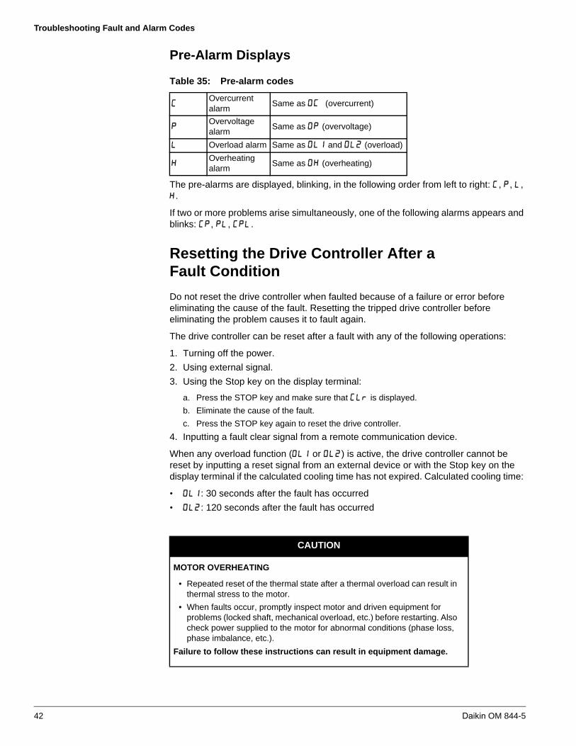
Pre-Alarm Displays
The pre-alarms are displayed, blinking, in the following order from left to right: , , , .
If two or more problems arise simultaneously, one of the following alarms appears and blinks: , , .
Resetting the Drive Controller After aFault Condition
Do not reset the drive controller when faulted because of a failure or error before eliminating the cause of the fault. Resetting the tripped drive controller before eliminating the problem causes it to fault again.
The drive controller can be reset after a fault with any of the following operations:
1. Turning off the power.
2. Using external signal.
3. Using the Stop key on the display terminal:
a. Press the STOP key and make sure that is displayed.
b. Eliminate the cause of the fault.
c. Press the STOP key again to reset the drive controller.
4. Inputting a fault clear signal from a remote communication device.
When any overload function ( or ) is active, the drive controller cannot be reset by inputting a reset signal from an external device or with the Stop key on the display terminal if the calculated cooling time has not expired. Calculated cooling time:
• : 30 seconds after the fault has occurred
• : 120 seconds after the fault has occurred
Table 35: Pre-alarm codes
Overcurrent alarm
Same as (overcurrent)
Overvoltage alarm
Same as (overvoltage)
Overload alarm Same as and (overload)
Overheating alarm
Same as (overheating)
CAUTION
MOTOR OVERHEATING
• Repeated reset of the thermal state after a thermal overload can result inthermal stress to the motor.
• When faults occur, promptly inspect motor and driven equipment forproblems (locked shaft, mechanical overload, etc.) before restarting. Alsocheck power supplied to the motor for abnormal conditions (phase loss,phase imbalance, etc.).
Failure to follow these instructions can result in equipment damage.
42 Daikin OM 844-5

Appendix A—Input Terminal Functions
Appendix A—Input Terminal FunctionsThe input terminals F, R, and RES can be configured with the settings in Table 36.
Table 36: Input Terminal Functions
Function No.
Code Function Action
- No function is assigned Disabled
* ST Standby terminalON: Ready for operation
OFF: Coast stop (gate off)
F Forward run commandON: Forward run OFF: Slowdown stop
R Reverse run commandON: Reverse run OFF: Slowdown stop
AD2Acceleration/deceleration 2 pattern selection
ON: Acceleration/deceleration 2
OFF: Acceleration/deceleration 1 or 3
SS1 Preset-speed command 1Selection of 7-speed with SS1 to SS3 (3 bits)
SS2 Preset-speed command 2
SS3 Preset-speed command 3
* RES Reset commandON: Acceptance of reset command
ON OFF: Fault reset
* EXTFault stop command from external input device
ON: Fault stop
DB DC braking command ON: DC braking
PID PID control prohibitedON: PID control prohibited
OFF: PID control permitted
PWENEPermission of parameter editing
ON: Parameter editing permitted
OFF: Parameter editing prohibited (If )
* ST+RESCombination of standbyand reset commands
ON: Simultaneous input from ST and RES
F+AD2Combination of forward run and acceleration/deceleration 2
ON: Simultaneous input from F and AD2
R+AD2Combination of reverse run and acceleration/deceleration 2
ON: Simultaneous input from R and AD2
F+SS1Combination of forward run and preset-speed command 1
ON: Simultaneous input from F and SS1
R+SS1Combination of reverse run and preset-speed command 1
ON: Simultaneous input from R and SS1
F+SS2Combination of forward run and preset-speed command 2
ON: Simultaneous input from F and SS2
R+SS2Combination of reverse run and preset-speed command 2
ON: Simultaneous input from R and SS2
F+SS3Combination of forward run and preset-speed command 3
ON: Simultaneous input from F and SS3
Daikin OM 844-5 43

Appendix A—Input Terminal Functions
R+SS3Combination of reverse run and preset-speed command 3
ON: Simultaneous input from R and SS3
F+SS1+AD2
Combination of forward run, preset-speed command 1 and acceleration/deceleration 2
ON: Simultaneous input from F, SS1 and AD2
R+SS1+AD2
Combination of reverse run, preset-speed command 1 and acceleration/deceleration 2
ON: Simultaneous input from R, SS1 and AD2
F+SS2+AD2
Combination of forward run, preset-speed command 2 and acceleration/deceleration 2
ON: Simultaneous input from F, SS2 and AD2
R+SS2+AD2
Combination of reverse run, preset-speed command 2 and acceleration/deceleration 2
ON: Simultaneous input from R, SS2 and AD2
F+SS3+AD2
Combination of forward run, preset-speed command 3 and acceleration/deceleration 2
ON: Simultaneous input from F, SS3 and AD2
R+SS3+AD2
Combination of reverse run, preset-speed command 3 and acceleration/deceleration 2
ON: Simultaneous input from R, SS3 and AD2
* FCHGFrequency commandforced switching
ON: (if )OFF:
VF2No.2 Switching of V/Hz setting
ON: No.2 V/Hz setting( , , , , )
OFF: No.1 V/Hz setting(Set value of , , , , )
MOT2No.2 motor switching
(VF2 + AD2 + OCS2)
ON: No.2 motor( , , , , , , , , )
OFF: No.1 motor (set value of , , , , , , , , )
* UPFrequency UP signal input from external contacts
ON: Increase in frequency
* DOWNFrequency DOWN signal input from external contacts
ON: Reduction in frequency
* CLRFrequency UP/DOWN cancellation signal input from external contacts
OFF ON: Resetting of UP/DOWN frequency by means of external contacts
* CLR+RES
Combination of frequency UP/DOWN cancellation and reset by means of external contacts
ON: Simultaneous input from CLR and RES
Table 36: Input Terminal Functions (continued)
Function No.
Code Function Action
44 Daikin OM 844-5

Appendix A—Input Terminal Functions
* EXTNInversion of fault stop command from external device
OFF: Fault stop
* OHThermal fault stop signal input from external device
ON: Fault stop
* OHNInversion of thermal fault stop command from external device
OFF: Fault stop
SC/LCForced switching from remote to local control
Enabled when remote control is exercised
ON: Local control (setting of , and )
OFF: Remote control
HDOperation holding (stop of 3-wire operation)
ON: F (forward run)/R: (reverse run) held, 3-wire operation
OFF: Slowdown stop
* CKWHDisplay cancellation of the cumulative power amount (kWh)
ON: Monitor display cancellation of the cumulative power amount (kWh)
* FORCEForced operation (factory configuration required)
ON: Forced operation mode in which operation is not stopped in the event of the occurrence of a soft fault (preset speed operation frequency 15) To use this function, the inverterneeds to be so configured at the factory.
OFF: Normal operation
* FIRE Fire-speed control
ON: Fire-speed operation ( ) Forced fire speed setting frequency
OFF: Normal operation
* STN Freewheel stop (gate off) ON: Freewheel stop (gate off)
* RESN Inversion of RESON: Acceptance of reset command
OFF ON: Fault reset
F+STCombination of forward run and standby
ON: Simultaneous input from F and ST
R+STCombination of reverse run and standby
ON: Simultaneous input from R and ST
OCS2Forced switching of stall prevention level 2
ON: Enabled at the value of
OFF: Enabled at the value of
* HDRYHolding of RY-RC terminal output
ON: Once turned on, RY-RC are held on.
OFF: The status of RY-RC changes in real time according to conditions.
* PRUNCancellation (clearing) of operation command from panel
0: Operation command canceled (cleared)
1: Operation command retained
ICLRPID control integral value clear
ON: PID control integral value always zero
OFF: PID control permitted
Table 36: Input Terminal Functions (continued)
Function No.
Code Function Action
Daikin OM 844-5 45

Appendix A—Input Terminal Functions
* When function , , , , , , , , , , , , , , , , , ,or is assigned to an input terminal board, the input terminal board is enabled even if the parameter command mode selection is set at 1 (panel).
ST+F+SS1Combination of standby, forward run and preset-speed command 1
ON: Simultaneous input from ST, F and SS1
ST+R+SS1Combination of standby, reverse run and preset-speed command 1
ON: Simultaneous input from ST, R and SS1
ST+F+SS2Combination of standby, forward run and preset-speed command 2
ON: Simultaneous input from ST, F and SS2
ST+R+SS2Combination of standby, reverse run and preset-speed command 2
ON: Simultaneous input from ST, R and SS2
ST+F+SS3Combination of standby, forward run and preset-speed command 3
ON: Simultaneous input from ST, F and SS3
ST+R+SS3Combination of standby, reverse run and preset-speed command 3
ON: Simultaneous input from ST, R and SS3
Table 36: Input Terminal Functions (continued)
Function No.
Code Function Action
46 Daikin OM 844-5
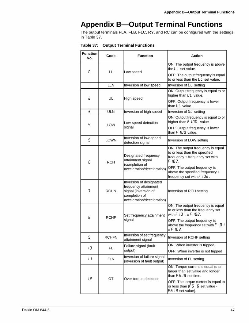
Appendix B—Output Terminal Functions
Appendix B—Output Terminal FunctionsThe output terminals FLA, FLB, FLC, RY, and RC can be configured with the settings in Table 37.
Table 37: Output Terminal Functions
Function No.
Code Function Action
LL Low speed
ON: The output frequency is above the set value.
OFF: The output frequency is equal to or less than the set value.
LLN Inversion of low speed Inversion of setting
UL High speed
ON: Output frequency is equal to or higher than value.
OFF: Output frequency is lower than value.
ULN Inversion of high speed Inversion of setting
LOWLow-speed detection signal
ON: Output frequency is equal to or higher than value.
OFF: Output frequency is lower than value.
LOWNInversion of low-speed detection signal
Inversion of LOW setting
RCH
Designated frequency attainment signal (completion of acceleration/deceleration)
ON: The output frequency is equal to or less than the specified frequency ± frequency set with .
OFF: The output frequency is above the specified frequency ± frequency set with .
RCHN
Inversion of designated frequency attainment signal (inversion of completion of acceleration/deceleration)
Inversion of RCH setting
RCHFSet frequency attainment signal
ON: The output frequency is equal to or less than the frequency set with ± .
OFF: The output frequency is above the frequency set with ± .
RCHFNInversion of set frequency attainment signal
Inversion of RCHF setting
FLFailure signal (fault output)
ON: When inverter is tripped
OFF: When inverter is not tripped
FLNInversion of failure signal (inversion of fault output)
Inversion of FL setting
OT Over-torque detection
ON: Torque current is equal to or larger than set value and longer than set time.
OFF: The torque current is equal to or less than ( set value - set value).
Daikin OM 844-5 47

Appendix B—Output Terminal Functions
OTNInversion of over-torque detection
Inversion of OT
RUN Start/Stop
ON: When operation frequency is output or during ( )
OFF: Operation stopped
RUNN Inversion of RUN/STOP Inversion of RUN setting
POL OL pre-alarm
ON: 50% or more of calculated value of overload protection level
OFF: Less than 50% of calculated value of overload protection level
POLN Inversion of OL pre-alarm Inversion of POL setting
POTOver-torque detection pre-alarm
ON: Torque current is equal to or larger than 70% of set value.
OFF: The torque current is below ( set value x 70% - set value).
POTNInversion of over-torque detection pre-alarm
Inversion of POT setting
PAL Pre-alarm
One of the following is turned on: ON POL, POHR, POT, MOFF, UC, OT, LL, stop, COT, and momentary power failure slowdown stop.
Or , , or issues an alarm
All the following are turned off: OFF POL, POHR, POT, MOFF, UC, OT, LL, stop, COT, and momentary power failure slowdown stop.
Or , , or issues no alarm
PALN Inversion of pre-alarm Inversion of PAL setting
UC Low-current detectionON: The output current is equal to or less than (set value) for (set time).
UCNInversion of low-current detection
Inversion of UC setting
HFL Significant failure
ON: , , , , , , , – , , , , , , or )
OFF: Failure other than the above
HFLNInversion of significant failure
Inversion of HFL setting
LFL Insignificant failure
ON: (– , – , , – , )
OFF: Failure other than the above
LFLNInversion of insignificant failure
Inversion of LFL setting
RDY1Ready for operation (including ST/RUN)
ON: Ready for operation (ST and RUN are also ON)
OFF: Others
Table 37: Output Terminal Functions (continued)
Function No.
Code Function Action
48 Daikin OM 844-5

Appendix B—Output Terminal Functions
RDY1NInversion of ready for operation (including ST/RUN)
Inversion of RDY1 setting
RDY2Ready for operation (excluding ST/RUN)
ON: Ready for operation (ST and RUN are not ON)
OFF: Others
RDY2NInversion of ready for operation (excluding ST/RUN)
Inversion of RDY2
FCVIB Frequency VIB selection
ON: VIB selected as frequency command
OFF: Terminal other than VIB selected as frequency command
FCVIBNInversion of frequency VIB selection
Inversion of FCVIB
FLRFault signal (put out also at the time of a restart)
ON: When inverter trips or restarts
OFF: When inverter does not trip or restart
FLRNInversion of failure signal (put out also at the time of a restart)
Inversion of FLR
OUT0 Specified data output 1
ON: Specified data from remote control FA50: BIT0= 1
OFF: Specified data from remote control FA50: BIT0= 0
OUT0NInversion of specified data output 1
Inversion of OUT0 setting
COTCumulative operation time alarm
ON: Cumulative operation time is equal to or longer than
OFF: Cumulative operation time is shorter than
COTNInversion of cumulative operation time alarm
Inversion of COT
LTA Parts replacement alarm
ON: Calculation for parts replacement time is equal to or longer than the preset time
ON: Calculation for parts replacement time is shorter than the preset time
LTANInversion of replacement alarm
Inversion of LTA
LI1 F terminal input signal
ON: The signal input to F terminal is ON
OFF: The signal input to F terminal is OFF
LI1NInversion of F terminal input signal
Inversion of LI1
LI2 R terminal input signal
ON: The signal input to R terminal is ON
OFF: The signal input to R terminal is OFF
Table 37: Output Terminal Functions (continued)
Function No.
Code Function Action
Daikin OM 844-5 49

Appendix B—Output Terminal Functions
LI2NInversion of R terminal input signal
Inversion of LI2
PIDFSignal in accordance of frequency command (VIA)
ON: Frequency commanded by or and that by VIA show the same value.
OFF: Frequency commanded by or and that by VIA show different values.
PIDFNInversion of signal in accordance of frequency command (VIA)
Inversion of PIDF setting
MOFF Undervoltage detectionON: Undervoltage detected
OFF: Other than undervoltage
MOFFNInversion of undervoltage detection
Inversion of MOFF
LOC Local/remote switching ON: Local mode
OFF: Remote mode
LOCNInversion of local/remote switching
Inversion of LOC
PTC PTC thermal alarm
ON: 60% and over the protection level by PTC
OFF: Normal condition
PTCNInversion of PTC thermal alarm
Inversion of PTC
PIDFBSignal in accordance of frequency command (VIB)
ON: Frequency commanded by or and that by VIB show the same value.
OFF: Frequency commanded by or and that by VIB show different values.
PIDFBNInversion of signal in accordance of frequency command (VIB)
Inversion of PIDFB setting
DisabledInvalid settings, always OFF (ignored)
Invalid settings, always OFF (ignored)
AOFF Always OFF Always OFF
AON Always ON Always ON
Table 37: Output Terminal Functions (continued)
Function No.
Code Function Action
50 Daikin OM 844-5

Appendix C—Receiving and Preliminary Inspection
Appendix C—Receiving and Preliminary InspectionThis appendix only applies to replacing VFD drives on existing equipment.
Before installing the drive controller, read pages 6–52 and follow all precautions.
Before removing the drive controller from its packaging, verify that the carton is not damaged from shipping. Damage to the carton usually indicates improper handling. If any damage is found, notify the carrier and your Daikin representative.
Storing and Shipping
If the drive controller is not immediately installed, store it in a clean, dry area where the ambient temperature is between -25F and +158F (-32C and +70C). If the drive controller must be shipped to another location, use the original shipping material and carton to protect the drive controller.
WARNING
DAMAGED PACKAGING
If the packaging appears damaged, it can be dangerous to open it or handle it.
Failure to follow this instruction can result in death, serious injury, or equipment damage.
WARNING
DAMAGED EQUIPMENT
Do not operate or install any drive controller that appears damaged.
Failure to follow this instruction can result in death, serious injury, or equipment damage.
Daikin OM 844-5 51

Appendix C—Receiving and Preliminary Inspection
Lifting and Handling
Precautions
WARNING
HANDLING AND LIFTING HAZARD
Keep the area below any equipment being lifted clear of all personnel and property. Use the lifting method illustrated in the figure below.
Failure to follow this instruction can result in death, serious injury, or equipment damage.
• MD2 drive controllers up to 25 hp can be removed fromtheir packaging and installed without a handling device.
• A hoist must be used for handling and lifting drivecontrollers of higher ratings.
• After removing the drive controller from its packaging,inspect it for damage. If any damage is found, notify thecarrier and your sales representative.
• Verify that the drive controller nameplate and label conformto the packing slip and corresponding purchase order.
WARNING
RISK OF TOPPLING
• Do not stand the drive upright.
• Keep the drive on pallet until ready to install.
Failure to follow these instructions can result in death, serious injury, or equipment damage.
DANGER
UNINTENDED EQUIPMENT OPERATION
Before turning on the drive controller or upon exiting the configuration menus, ensure that the inputs assigned to the Run command are in a state that will not cause the drive controller to run. Otherwise, the motor can start immediately
Failure to follow this instruction will result in death or serious injury.
CAUTION
INCOMPATIBLE LINE VOLTAGE
Before turning on and configuring the drive controller, ensure that the line voltage is compatible with the line voltage range specified on the drive controller nameplate. The drive controller can be damaged if the line voltage is not compatible.
Failure to follow this instruction can result in injury or equipment damage.
45°max.
52 Daikin OM 844-5

Appendix C—Receiving and Preliminary Inspection
The symbols used in Table 38 are as follows:
• W: Width
• H: Height
• D: Depth
• W1: Mounting dimension (horizontal)
• H1: Mounting dimension (vertical)
• H2: Height of EMC plate mounting area
.
Table 38: Outside Dimensions and Weight
Voltage class
Applicable motor
hp
Dimensions in. (mm)Refer to drawing:
Approx. weight lb
(kg)W H D W1 H1 H2
3-phase 230 V
14
(105)5.6
(143)5.9
(150)3.6 (93)
4.7 (121.5)
2(50)
A4.0
(1.8)2
3
4 5.5 (140)
7.2 (184)
5.9 (150)
4.9 (126)
6.1 (157)
1.8 (48)
B6.7
(3.1)5
7.5 7 (180)
9.1 (232)
6.7 (170)
6.3 (160)
8.2 (210)
2.95 (75)
C13.5(6.1)10
159.6
(245)13
(329.5)7.5
(190)8.8
(225)11.6 (295)
2.95 (75)
D25.4
(11.5)20
25
309.4
(240)16.5 (420)
8.4 (214)
8.1 (206)
15.8 (403)
4.8(122)
E60.6
(27.4)
4012.5 (320)
24.8 (630)
11.4 (290)
11 (280)
23.8 (604.5)
4.7(118)
F85.3
(38.7)
3-phase 460 V
14
(105)5.6
(143)5.9
(150)3.6 (93)
4.7 (121.5)
2(50)
A4.4
(2.0)2
3
45.5
(140)7.2
(184)5.9
(150)4.9
(126)6.1
(157)1.8 (48)
B7.4
(3.4)5
7.5
10 7 (180)
9.1 (232)
6.7 (170)
6.3 (160)
8.2 (210)
2.95 (75)
C14.3(6.5)15
20 9.6 (245)
13 (329.5)
7.5 (190)
8.8 (225)
11.6 (295)
2.95 (75)
D25.75(11.7)25
30 9.4 (240)
16.5 (420)
8.4 (214)
8.1 (206)
15.8 (403)
4.8(122)
E51.81(23.5)40
50 9.4 (240)
21.7(550)
11.4 (290)
8.1(206)
20.8(529)
5.29(113)
G58.3
(26.4)60
75 12.5 (320)
24.8 (630)
11.4 (290)
11.0(280)
23.8(604.5)
4.7(118)
G87.5
(39.7)100
Daikin OM 844-5 53

Appendix C—Receiving and Preliminary Inspection
NOTE: In the following figures, dimensions common to all drive controllers are shown with numeric values, not with symbols. The model shown in Drawing A is fixed at two points: in the upper left and lower right corners.
Drawing A
Drawing B
5.1
(130
)
R 0.1 (2.5)
4.8
(121
.5)
(Inst
alla
tion
dim
ensi
on)
3.7 (93)(Installation dimension)
Ø0.2 (5)
5.9
(150
)
2.5
(64.
5)
2.0
(50)
3.7 (95)
M5 4-M4
EMC plate
0.51(13)
0.6(14)
6.7
(170
)
2-R 0.1 (2.5)
2.6
(65)
6.2
(157
)(In
stal
latio
n di
men
sion
)
5.0 (126)(Installation dimension)
2-Ø1.0 (25)
5.9
(150
) 2.4
(62)
1.9
(48)
3.7 (95)
M5 4-M4
EMC plate
5.5 (140)
54 Daikin OM 844-5

Appendix C—Receiving and Preliminary Inspection
Drawing C
Drawing D
7.1 (180)7.1 (180)
7.0 (178)7.0 (178)
2-R 0.1 (2.5)2-R 0.1 (2.5)
6.3 (160)6.3 (160)(Installation dimension)(Installation dimension)
8.7
(220
)8.
7 (2
20)
6.7
(170
)6.
7 (1
70)
3.4
(87)
3.4
(87)
3.0
(75)
3.0
(75)
0.5
0.5
(12)
(12)
8.3
(210
)8.
3 (2
10)
(Inst
alla
tion
dim
ensio
n)(In
stal
latio
n di
men
sion)
0.2
0.2
(5)
(5)
R 0.1 (
2.5)
R 0.1 (
2.5)
0.3
0.3 (8)
(8)
M5M5 4-M44-M4EMC plateEMC plate
Ø0.5 (13)
0.5 (13)
9.6 (245)9.6 (245)
7.8 (198)7.8 (198)
8.9 (225)8.9 (225) (Installation dimension) (Installation dimension)
7.5
(190
)7.
5 (1
90)
12.2
(310
)12
.2 (3
10)
0.8
0.8
(19.
5)(1
9.5)
11.6
(295
)11
.6 (2
95)
(Inst
alla
tion
dim
ensi
on)
(Inst
alla
tion
dim
ensi
on)
0.3
0.3
(7)
(7)
Ø 0.6 (14)
0.6 (14) R 0.1 (
3)
R 0.1 (
3)
0.4
0.4
(9)
(9)
3.7
(94.
5)3.
7 (9
4.5)
3.0
(75)
3.0
(75)
M4M4 4-M44-M4EMC plateEMC plate
2-R 0.1 (3)2-R 0.1 (3)
Daikin OM 844-5 55

Appendix C—Receiving and Preliminary Inspection
Drawing E
Drawing F
9.4 (240)9.4 (240) 0.10.1(3)(3)
0.10.1(3)(3)
8 (206)8 (206) (Installation dimension) (Installation dimension)
8.4
(214
)8.
4 (2
14)
17 (4
20)
17 (4
20)
16 (4
03)
16 (4
03)
(Inst
alla
tion
dim
ensi
on)
(Inst
alla
tion
dim
ensi
on)
Ø0.6 (15)
0.6 (15) R 0.1 (
3)
R 0.1 (
3)
0.5
0.5
(12)
(12)
2-R 0.1 (3)2-R 0.1 (3)
4-4-Ø0.6(16)0.6(16)
12.6 (320)12.6 (320) 0.10.1(3)(3)
0.10.1(3)(3)
11 (280)11 (280) (Installation dimension) (Installation dimension)
11.4
(290
)11
.4 (2
90)
24.8
(630
)24
.8 (6
30)
23.8
(604
.5)
23.8
(604
.5)
(Ins
talla
tion
dim
ensi
on)
(Ins
talla
tion
dim
ensi
on)
Ø0.6 (15)
0.6 (15) R 0.1 (
3)
R 0.1 (
3)
0.5
0.5
(12)
(12)
2-R 0.1 (3)2-R 0.1 (3)
4-4-Ø0.6 (16)0.6 (16)
56 Daikin OM 844-5
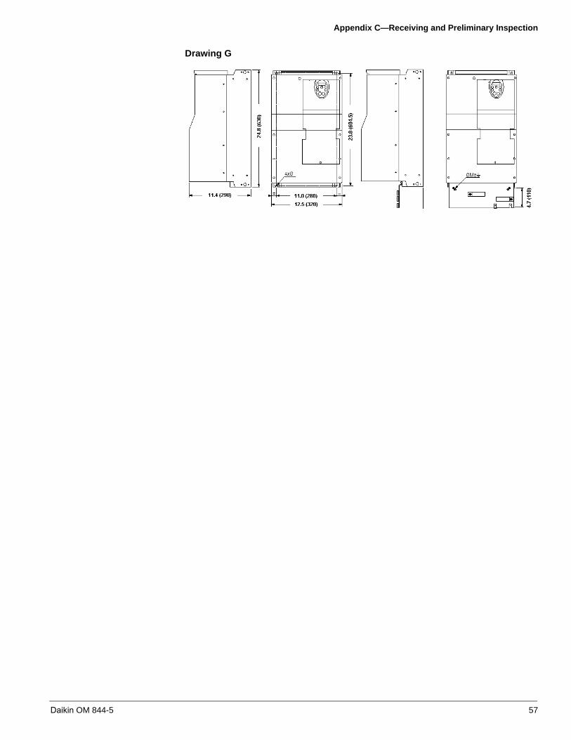
Appendix C—Receiving and Preliminary Inspection
Drawing G
Daikin OM 844-5 57

Appendix D—Wiring Recommendations
Appendix D—Wiring RecommendationsNo field wiring is required except in the following instances:
Controls by others - Daikin provides examples of typical control wiring (see “Appendix L—Controls by Others for SAF, RAF, and EAF Applications” on page 82), but control wiring ultimately is the customer’s responsibility. All power wiring is factory installed and must not be changed.
Replacing a drive in an existing unit - Any replacement VFD must be wired exactly as the original VFD. This applies to power and control wiring. Carefully examine the original wiring and the wiring schematic before removing the original VFD.
Field Control Wiring and General Background for Reconnecting Wiring to a Replacement VFD
Good wiring practice requires the separation of control wiring from all power (line) wiring. In addition, power wiring to the motor must have the maximum possible separation from all other power wiring, whether from the same drive controller or other drive controllers. Do not run power and control wiring, or multiple power wiring, in the same conduit. This separation reduces the possibility of coupling electrical transients from power circuits into control circuits or from motor power wiring into other power circuits.
Follow the practices below when wiring MD2 drive controllers:
• Verify that the voltage and frequency of the input supply line and the voltage,frequency, and current of the motor match the rating on the drive controllernameplate.
• Use metallic conduit for all drive controller wiring. Do not run control and powerwiring in the same conduit.
• Separate the metallic conduits carrying power wiring or low-level control wiring byat least 76 mm (3 in.).
• Separate the non-metallic conduits or cable trays carrying power wiring from themetallic conduit carrying control wiring by at least 305 mm (12 in.).
• Whenever power and control wiring cross, the metallic conduits and non-metallicconduits or trays must cross at right angles.
• Equip all inductive circuits near the drive (such as relays, contactors, and solenoidvalves) with noise suppressors, or connect them to a separate circuit.
WARNING
IMPROPER WIRING PRACTICES
• Follow the wiring practices described in this document in addition to those already required by the National Electrical Code and local electricalcodes.
• The drive controller will be damaged if input line voltage is applied to theoutput terminals (U/T1, V/T2, W/T3).
• Check the power connections before energizing the drive controller.
• If replacing another drive controller, verify that all wiring connections to theMD2 drive controller comply with all wiring instructions in this manual.
Failure to follow these instructions can result in death, serious injury, or equipment damage.
58 Daikin OM 844-5
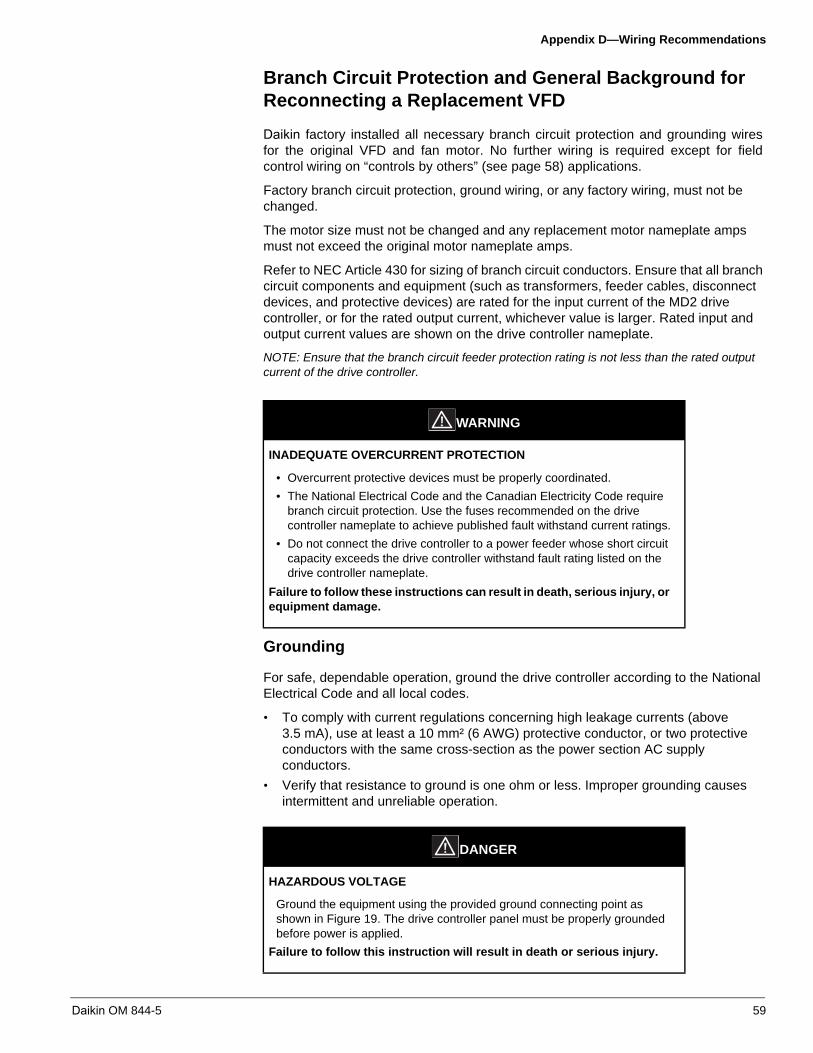
Appendix D—Wiring Recommendations
Branch Circuit Protection and General Background for Reconnecting a Replacement VFD
Daikin factory installed all necessary branch circuit protection and grounding wires for the original VFD and fan motor. No further wiring is required except for field control wiring on “controls by others” (see page 58) applications.
Factory branch circuit protection, ground wiring, or any factory wiring, must not be changed.
The motor size must not be changed and any replacement motor nameplate amps must not exceed the original motor nameplate amps.
Refer to NEC Article 430 for sizing of branch circuit conductors. Ensure that all branch circuit components and equipment (such as transformers, feeder cables, disconnect devices, and protective devices) are rated for the input current of the MD2 drive controller, or for the rated output current, whichever value is larger. Rated input and output current values are shown on the drive controller nameplate.
NOTE: Ensure that the branch circuit feeder protection rating is not less than the rated output current of the drive controller.
Grounding
For safe, dependable operation, ground the drive controller according to the National Electrical Code and all local codes.
• To comply with current regulations concerning high leakage currents (above3.5 mA), use at least a 10 mm² (6 AWG) protective conductor, or two protectiveconductors with the same cross-section as the power section AC supplyconductors.
• Verify that resistance to ground is one ohm or less. Improper grounding causesintermittent and unreliable operation.
WARNING
INADEQUATE OVERCURRENT PROTECTION
• Overcurrent protective devices must be properly coordinated.
• The National Electrical Code and the Canadian Electricity Code requirebranch circuit protection. Use the fuses recommended on the drivecontroller nameplate to achieve published fault withstand current ratings.
• Do not connect the drive controller to a power feeder whose short circuitcapacity exceeds the drive controller withstand fault rating listed on thedrive controller nameplate.
Failure to follow these instructions can result in death, serious injury, or equipment damage.
DANGER
HAZARDOUS VOLTAGE
Ground the equipment using the provided ground connecting point as shown in Figure 19. The drive controller panel must be properly grounded before power is applied.
Failure to follow this instruction will result in death or serious injury.
Daikin OM 844-5 59

Appendix D—Wiring Recommendations
Make certain Daikin factory installed grounding is maintained (see “Proper Grounding” in Figure 19). Do not loop the ground cables or connect them in series (see “Improper Grounding” in Figure 19).
208 - 230 Volt, 7.5 - 10 HP VFDs
208 - 230 V, 7.5 -10 HP VFD nameplate amps may be rated 1 amp less than the motor nameplate amps. Amp disparity between VFD and motor nameplates is normal for this application.
Power Terminals
To access the power terminals, open the cover using one of the methods illustrated in Figure 20.
Figure 19: Grounding Multiple Drive Controllers
Figure 20: Power Terminal Access
Drive Controller
Drive Controller
Drive Controller
Drive Controller
Drive Controller
Drive Controller
YES NO
Drive Controller
Drive Controller
Drive Controller
Proper ImproperGrounding Grounding
Example MD2, 2 hp Example MD2, 30 hp
60 Daikin OM 844-5

Appendix D—Wiring Recommendations
NOTE: The PA/+, and PC/- terminals can only be used to measure the DC bus voltage. Do not remove the jumper between PA/+ and PO.
Table 39: Power Terminal Functions
Terminals Function
Ground terminal
R/L1S/L2T/L3
Power supply
U/T1V/T2 W/T3
Outputs to the motor
PO DC bus (+) polarity (do not use)
PA/+ DC bus (+) polarity
PB DC bus connection (do not use)
PC/- DC bus (–) polarity
Table 40: Power Terminal Characteristics
MD2H Maximum Wire Size Tightening Torque
Voltage hp mm² AWG Nm (lb-in)
230 V
1–3 6 10 1.3 (10.7)
4 6 10 1.3 (10.7)
5 6 10 1.3 (10.7)
7.5 16 6 2.5 (22.3)
10 16 6 2.5 (22.3)
15 25 3 4.5 (40.1)
20 25 3 4.5 (40.1)
25 25 3 2.5 (22.3)
30 50 1/0 12 (106.2)
40 150 300 kcmil 41 (362.9)
460 V
1–7.5 6 10 1.3 (10.7)
10 16 6 2.5 (22.3)
15 16 6 2.5 (22.3)
20 25 3 4.5 (40.1)
25 25 3 4.5 (40.1)
30 50 1/0 12 (106.2)
40 50 1/0 12 (106.2)
50 50 1/0 12 (106.2)
60 50 1/0 12 (106.2)
75–100 150 300 kcmil 41 (360)
Daikin OM 844-5 61
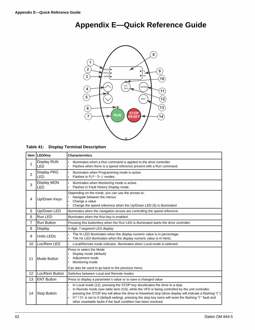
Appendix E—Quick Reference Guide
Appendix E—Quick Reference Guide
RUNPRGMON
%
Hz
MODELocRem
ENT
RUN STOPRESET
1
2
3
4
5
6
7
8
9
10
11
12
13
14
Table 41: Display Terminal Description
Item LED/Key Characteristics
1Display RUN LED
• Illuminates when a Run command is applied to the drive controller.• Flashes when there is a speed reference present with a Run command.
2Display PRG LED
• Illuminates when Programming mode is active.• Flashes in modes.
3Display MON LED
• Illuminates when Monitoring mode is active.• Flashes in Fault History Display mode.
4 Up/Down Keys
Depending on the mode, you can use the arrows to:• Navigate between the menus• Change a value• Change the speed reference when the Up/Down LED (5) is illuminated
5 Up/Down LED Illuminates when the navigation arrows are controlling the speed reference.
6 Run LED Illuminates when the Run key is enabled.
7 Run Button Pressing this button/key when the Run LED is illuminated starts the drive controller.
8 Display 4-digit, 7-segment LED display
9 Units LEDs• The % LED illuminates when the display numeric value is in percentage.• The Hz LED illuminates when the display numeric value is in Hertz.
10 Loc/Rem LED • Local/Remote mode indicator. Illuminates when Local mode is selected.
11 Mode Button
Press to select the Mode • Display mode (default)• Adjustment mode• Monitoring mode
Can also be used to go back to the previous menu
12 Loc/Rem Button Switches between Local and Remote modes
13 ENT Button Press to display a parameter’s value or to save a changed value
14 Stop Button
• In Local mode (12), pressing the STOP key decelerates the drive to a stop• In Remote mode (see table item #10), while the VFD is being controlled by the unit controller,
pressing the STOP key will allow the drive to freewheel stop (drive display will indicate a flashing “”)• If is set to 0 (default setting), pressing the stop key twice will reset the flashing “” fault and
other resettable faults if the fault condition has been resolved
62 Daikin OM 844-5

Appendix E—Quick Reference Guide
Mode Navigation
Monitoring Mode
The Monitoring mode displays drive controller operational data in real time. To access the Monitoring mode, press the MODE key until the MON LED is illuminated. Then press the UP and Down keys to view up to 30 different types of data.
6 0.0 RUNPRGMON
%
Hz f r - fRUNPRGMON
%
Hz
MODE MODE MODE
ATV21 Drive Conroller Power Up
a.u.f.RUNPRGMON
%
Hz
MODE
25 Other Parameters
f 6 0.0RUNPRGMON
%
Hz
MODE
MODE
0.0 RUNPRGMON
%
Hz
f r - fRUNPRGMON
%
Hz
a.u.f.RUNPRGMON
%
Hz
n - - -RUNPRGMON
%
Hz
t 0.1 0RUNPRGMON
%
Hz
C 8 0 RUNPRGMON
%
Hz
KeyMode Key
Up/Down Keys
MODE
Daikin OM 844-5 63
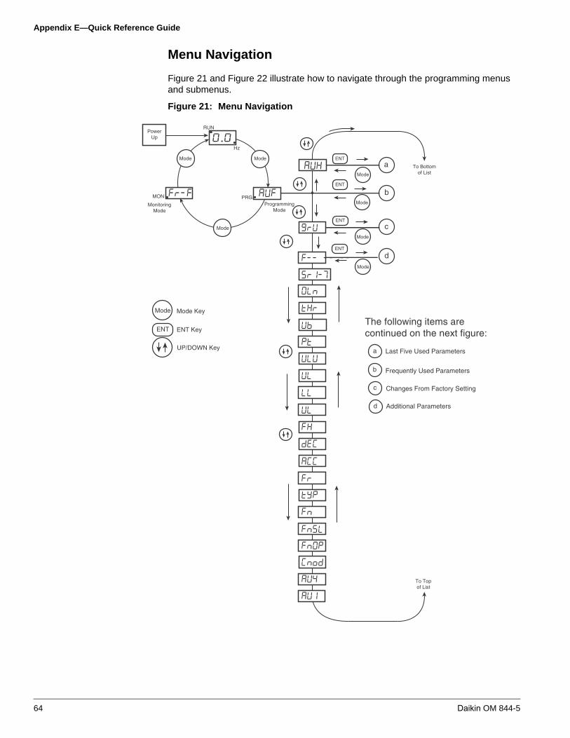
Appendix E—Quick Reference Guide
Menu Navigation
Figure 21 and Figure 22 illustrate how to navigate through the programming menus and submenus.
Figure 21: Menu Navigation
0.0Mode Mode
Mode
Fr-F AUFMON PRG
RUN
Hz
PowerUp
ProgrammingMode
MonitoringMode
Sr1-7
OLN
tHr
ub
Pt
uLu
uL
UL
LL
FH
dEC
ACC
Fr
tyP
CnoD
FnOP
FnSL
Fn
AU4
AU1
F-- -- --
GrU
ENT
Mode
a
ENT
ENT
ENT
Mode
Mode
Mode
b
c
d
AUH To Bottomof List
To Topof List
Mode
ENT
Mode Key
ENT Key
UP/DOWN Key a Last Five Used Parameters
b Frequently Used Parameters
c Changes From Factory Setting
d Additional Parameters
The following items are continued on the next figure:
64 Daikin OM 844-5

Appendix E—Quick Reference Guide
Figure 22: Menu Navigation (continued)
OLN
LL
AUHENT
Mode*
*
*
*
*
a History parameters
HEAD
tHr
END
AU1
ACC
dEC
Fn
UL
LL
Pt
uLu
uL
AUFENT
Mode
b Quick menu
c User parameters
U--F3
3
U--F
U--F
3
U---
U--r2
2
2
U--r3
U--r
GrUENT
Mode
1
4
1
F911
ENT
Mode
*
*
d Extended parameters
F912
F102
F101
F100
To Bottomof List
To Topof List
F---
1. Pressing the UPkey searches theparameter liststarting with the first one changed.
2. Pressing theDOWN keysearches theparameter liststarting with the last one changed.
3. The number ofparametersdisplayed within theGrU menu dependsupon how manyhave been alteredfrom their factorysettings.
4. When all thechangedparameters havebeen displayed, thedisplay returns toGrU.
Daikin OM 844-5 65
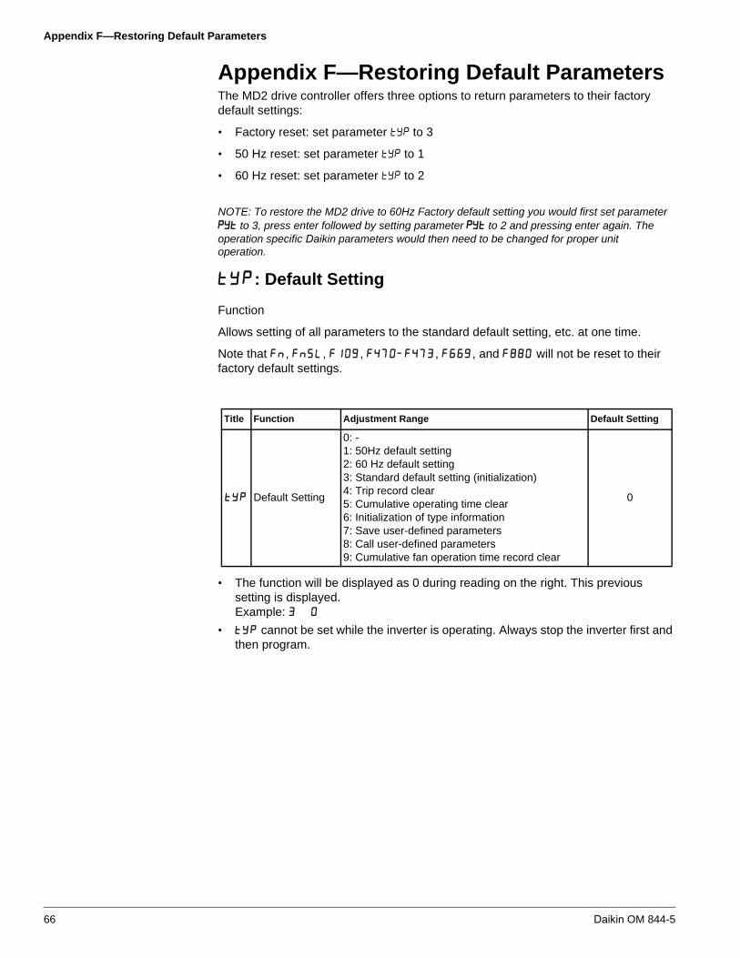
Appendix F—Restoring Default Parameters
Appendix F—Restoring Default ParametersThe MD2 drive controller offers three options to return parameters to their factory default settings:
• Factory reset: set parameter to 3
• 50 Hz reset: set parameter to 1
• 60 Hz reset: set parameter to 2
NOTE: To restore the MD2 drive to 60Hz Factory default setting you would first set parameter to 3, press enter followed by setting parameter to 2 and pressing enter again. The operation specific Daikin parameters would then need to be changed for proper unit operation.
: Default Setting
Function
Allows setting of all parameters to the standard default setting, etc. at one time.
Note that , , , , , and will not be reset to their factory default settings.
• The function will be displayed as 0 during reading on the right. This previoussetting is displayed.Example:
• cannot be set while the inverter is operating. Always stop the inverter first andthen program.
Title Function Adjustment Range Default Setting
Default Setting
0: -1: 50Hz default setting2: 60 Hz default setting3: Standard default setting (initialization)4: Trip record clear5: Cumulative operating time clear6: Initialization of type information7: Save user-defined parameters8: Call user-defined parameters9: Cumulative fan operation time record clear
0
66 Daikin OM 844-5

Appendix F—Restoring Default Parameters
Programmed Value
• 50 Hz default setting ( = )Setting at causes the following parameters to e set for operation using abase frequency of 50 Hz (this does not change the setting of any otherparameters).Parameter , , , , , , : 50 HzParameter : According to model
• 60 Hz default setting ( = )Setting at causes the following parameters to e set for operation using abase frequency of 60 Hz (this does not change the setting of any otherparameters).Parameter , , , , , , : 60 HzParameter : According to model
• Default setting ( = )Setting to will return all parameters to the standard values that wereprogrammed at the factory.When is set to , will be displayed for a short time after the setting andwill then be erased and the original indication will be displayed. Trip historydata will be cleared at this time.
• Trip clear ( = )Setting to initializes the past four sets of recorded error history data.The parameter does not change.
• Cumulative operation time clear ( = )Setting to resets the cumulative operation time to the initial value of zero.
• Save user setting parameters ( = )Setting to saves the current settings of all parameters.
• Load user setting parameters ( = )Setting to loads parameter settings to (calls up) those saved by setting to .By setting to or 8, you can use parameters as your own default parameters.
• Cumulative fan operation time record clear ( = )Setting to resets the fan cumulative operation time to the initial value ofzero.Set this parameter when replacing the cooling fan.
NOTE: You must stop the drive controller before changing the setting of .
NOTE: The following parameters are not affected by setting of 1, 2, and 3: , , , through , and .
NOTE: The setting display of this parameter contains two numbers. The left-most number displays the last operation performed. The right-most number indicates the pending operation and should be adjusted for the action desired.
Daikin OM 844-5 67

Appendix F—Restoring Default Parameters
NOTE: A 60 Hz reset on a 460V drive controller sets the rated voltage (and) to 400V.
Table 42: Parameters whose values do not change if a reset is performed
Parameter Description Unit Min.
ValueMax. Value
Default Value
Meter adjustment 1 1 1280 145
Meter selections 1 0 19 0
Analog/contact input function selection (VIA/VIB) 1 0 2 0
VIA bias 1 0 225 128
VIA gain 1 0 255 148
VIB bias 1 0 255 128
VIB gain 1 0 255 148
Free notes 1 0 65535 0
Table 43: Default Parameters
Code Function Description UnitMin.
ValueMax. Value
Default Value
Automatic acceleration/deceleration 1 0 2 1
Automatic function setting 1 0 4 0
Command mode selection 1 0 2 0
Frequency setting mode selection 1 1 1 5 1
Meter selection 1 0 19 0
Meter adjustment 1 1 1280 145
Default setting 1 0 9 0
Forward/reverse run selection (Operation panel) 1 0 3 0
Acceleration time 1 0.1sec 0 3200 10
Deceleration time 1 0.1sec 0 3200 10
Maximum frequency 0.01Hz 30 200 50
Upper limit frequency 0.01Hz 1 80 50
Lower limit frequency 0.01Hz 0 60 0
Base frequency 1 0.01Hz 25 200 50
Base frequency voltage 1 0.1V 50 660
V/F control mode selection 1 1 0 6 1
Torque boost 1 0.10% 0 30 5
Motor electronic-thermal protection level 1 1% 10 100 100
Electric-thermal protection characteristic selection 1 0 7 0
Preset-speed operation frequency 1 0.01Hz 0 60 15
Preset-speed operation frequency 2 0.01Hz 0 60 20
Preset-speed operation frequency 3 0.01Hz 0 60 25
Preset-speed operation frequency 4 0.01Hz 0 60 30
Preset-speed operation frequency 5 0.01Hz 0 60 35
Preset-speed operation frequency 6 0.01Hz 0 60 40
Preset-speed operation frequency 7 0.01Hz 0 60 45
Low-speed signal output frequency 0.01Hz 0 80 0
Speed reach setting frequency 0.01Hz 0 80 0
Speed reach detection band 0.01Hz 0 80 2.5
2nd always-active function selection 1 0 71 0
Analog/contact input function selection (VIA/VIB) 1 0 2 0
Always-active function selection 1 0 71 1
Input terminal selection1 (F) 1 0 71 2
Input terminal selection 2 (R) 1 0 71 6
68 Daikin OM 844-5

Appendix F—Restoring Default Parameters
Input terminal selection 3 (RST) 1 0 71 10
Input terminal selection 8 (VIA) 1 0 71 7
Output terminal selection 1A (RY-RC) 1 0 255 4
Output terminal selection 3 (FL) 1 0 255 11
Output terminal selection 1B (RY-RC) 1 0 255 255
Output terminal logic selection (RY-RC/OUT-NO) 1 0 1 0
Frequency command agreement detection range 0.01Hz 0 80 2.5
Base frequency 2 0.01Hz 25 200 50
Base frequency voltage 2 0.1V 50 660
Torque boost 2 0.10% 0 30 5
Motor electronic-thermal protection level 2 1% 10 100 100
Stall prevention level 2 1% 10 111 110
Frequency priority selection 1 0 1 0
VIA input point 1 setting 1% 0 100 0
VIA input point 1 frequency 0.01Hz 0 200 0
VIA input point 2 setting 1% 0 100 100
VIA input point 2 frequency 0.01Hz 0 200 50
Frequency setting mode selection 2 1 1 5 2
VIB input point 1 setting 1% 0 100 0
VIB input point 1 frequency 0.01Hz 0 200 0
VIB input point 2 setting 1% 0 100 100
VIB input point 2 frequency 0.01Hz 0 200 50
Starting frequency setting 0.01Hz 1 10 0.5
Operation starting frequency 0.01Hz 0 80 0
Operation starting frequency hysteresis 0.01Hz 0 80 0
DC braking starting frequency 0.01Hz 0 80 0
DC braking current 1% 0 100 50
DC braking time 0.1sec 0 20 1
Time limit for lower-limit frequency operation 0.1sec 0 600 0
Input from external contacts-UP response time 0.1sec 0 10 0.1
Input from external contacts-UP frequency step width 0.01Hz 0 80 0.1
Input from external contacts-DOWN response time 0.1sec 0 10 0.1
Input from external contacts-DOWN freq step width 0.01Hz 0 80 0.1
Initial value of UP/DOWN frequency 0.01Hz 0 60 0
Saving of changed value of UP/DOWN frequency 1 0 1 1
Jump frequency 1 0.01Hz 0 80 0
Jump width 1 0.01Hz 0 30 0
Jump frequency 2 0.01Hz 0 80 0
Jump width 2 0.01Hz 0 30 0
Jump frequency 3 0.01Hz 0 80 0
Jump width 3 0.01Hz 0 30 0
Preset-speed operation frequency 15 0.01Hz 0 60 50
Selection of bump-less 1 0 1 1
PWM carrier frequency 0.1kHz 6 16
Auto-restart control selection 1 0 4 3
Regeneration power ride-through control (Deceleration stop) 1 0 2 0
Retry selection (number of times) 1 0 10 3
Table 43: Default Parameters
Code Function Description UnitMin.
ValueMax. Value
Default Value
Daikin OM 844-5 69

Appendix F—Restoring Default Parameters
Over-voltage limit operation (Slowdown stop mode selection) 1 0 3 2
Supply voltage correction (limitation of output voltage) 1 0 3 3
Reverse-run prohibition 1 0 2 1
Random mode 1 0 1 0
Carrier frequency control mode selection 1 0 3 1
Drooping gain 1% 0 100 0
Drooping insensitive torque band 1% 0 100 10
PID control waiting time 1sec 0 2400 0
PID control 1 0 2 0
Proportional gain 0.01 0 100 0.3
Integral gain 0.01 0 100 0.2
Differential gain 0.01 0 3 0
Auto-tuning 1 0 2 0
Slip frequency gain 1% 0 150 50
Motor constant #1 (primary resistance) 0.10% 0 30
Motor rated current 0.1A 0 200
Motor no-load current 1% 10 100
Motor rated speed 1min-1 100 15000
Speed control response coefficient 1 1 150 40
Speed control stability coefficient 1 1 100 20
VIA bias 1 0 255 128
VIA gain 1 0 255 148
VIB bias 1 0 255 128
VIB gain 1 0 255 148
Exciting strengthening coefficient 1% 100 130 100
Factory adjustment 1 1 0 9999 0
Factory adjustment2 1 0 9999 442
Factory adjustment3 0.1 0 300 100
Stall cooperation gain at field weakening zone 1 1 10 250 100
Stall cooperation gain at field weakening zone 2 1 50 150 100
Motor adjustment factor 1 0 200 70
Maximum voltage adjustment factor 1% 90 120 104
Carrier change adjustment factor 0.1kHz 0 14 14
Acceleration time 2 0.1sec 0 3200 20
Deceleration time 2 0.1sec 0 3200 20
Acceleration/deceleration 1 pattern 1 0 2 0
Acceleration/deceleration 2 pattern 1 0 2 0
Acceleration/deceleration selection (1/2/3) 1 1 2 1
Acceleration/deceleration 1 and 2 switching frequency 0.01Hz 0 60 0
S-pattern lower-limit adjustment amount 1% 0 50 10
S-pattern upper-limit adjustment amount 1% 0 50 10
Stall prevention level 1 1% 10 111 110
Inverter trip retention selection 1 0 1 0
Emergency stop selection 1 0 2 0
Emergency DC braking time 0.1sec 0 20 1
Output phase failure detection mode selection 1 0 5 3
Motor 150%-overload time limit 1sec 10 2400 300
Table 43: Default Parameters
Code Function Description UnitMin.
ValueMax. Value
Default Value
70 Daikin OM 844-5

Appendix F—Restoring Default Parameters
Input phase failure detection mode selection 1 0 1 1
Hysteresis for small current detection 1% 1 20 10
Low current trip/alarm 1 0 1 0
Small current detection current 1% 0 100 0
Small current detection time 1sec 0 255 0
Detection of output short-circuit during start-up 1 0 3 0
Over-torque trip/alarm selection 1 0 1 0
Over-torque detection level 1% 0 250 130
Over-torque detection time 0.1sec 0 10 0.5
Over-torque detection level hysteresis 1% 0 100 10
Cumulative operation time alarm setting 0.1 0 1000 610
Over-voltage stall protection level 1% 100 150 140
Under-voltage trip/alarm selection 1 0 2 0
Thermal memory selection 1 0 1 0
Trip at VIA low level input mode 1% 0 100 0
Annual avg ambient temp (calculation for life alarms) 1 1 6 3
Selection of PTC thermal 1 0 2 0
Detection level of PTC 1ohm 100 9999 3000
Forced/Fire-speed control selection 1 0 1 0
Inclination characteristic of analog output 1 0 1 1
Meter bias 1% 0 100 0
Prohibition of change of parameter settings 1 0 1 0
Unit selection 1 0 1 1
Free unit selection 0.01 0 200 0
Inclination characteristic of free unit display 1 0 1 1
Free unit display bias 0.01Hz 0 80 0
Free step 1 (pressing a panel key once) 0.01Hz 0 80 0
Free step 2 (panel display) 1 0 255 0
Standard monitor display selection 1 0 10 0
Panel stop pattern 1 0 1 0
Prohibition of freq. setting on the operation panel (FC) 1 0 1 0
Panel operation prohibition (Local/Remote keys) 1 0 1 0
Panel operation prohibition (RUN/STOP keys) 1 0 1 0
Prohibition of panel emergency stop operation 1 0 1 0
Prohibition of panel reset operation 1 0 1 0
Selection of AUF 1 0 1 0
Selection of watt hour memory 1 0 1 1
Display unit selection of watt hour 1 0 3 0
Communication band speed 1 0 1 1
Parity 1 0 2 1
Inverter number; SAF=1;RAF=2;HW=3 1 0 247 1
Communication error trip time 1sec 0 100 3
Communication waiting time 0.01sec 0 2 0
Setting master & slave for comm between inverters 1 0 4 0
Communication input point 1 setting 1% 0 100 0
Communication input point 1 frequency 0.01Hz 0 200 0
Communication input point 2 setting 1% 0 100 100
Table 43: Default Parameters
Code Function Description UnitMin.
ValueMax. Value
Default Value
Daikin OM 844-5 71

Appendix F—Restoring Default Parameters
Communication input point 2 frequency 0.01Hz 0 200 0
Selection of communication protocol 1 0 4 1
Inverter action at network & communication break 1 0 4 0
Number of motor poles for comm speed calculation 1 1 8 2
Block write data 1 1 0 6 0
Block write data 2 1 0 6 0
Block read data 1 1 0 11 0
Block read data 2 1 0 11 0
Block read data 3 1 0 11 0
Block read data 4 1 0 11 0
Block read data 5 1 0 11 0
Free notes 1 0 65535 0
Parameter for option 1 1 0 65535 0
Parameter for option 2 1 0 65535 0
Parameter for option 3 1 0 65535 0
Parameter for option 4 1 0 65535 0
Parameter for option 5 1 0 65535 0
Parameter for option 6 1 0 65535 0
Parameter for option 7 1 0 65535 0
Parameter for option 8 1 0 65535 0
Parameter for option 9 1 0 65535 0
Parameter for option 10 1 0 65535 0
Step-out detection current level (for PM motors) 1% 10 150 100
Step-out detection time (for PM motors) 0.1sec 0 25 0.0
q-axis self-inductance (for PM) 0.01mH 0 650 0.00
Table 43: Default Parameters
Code Function Description UnitMin.
ValueMax. Value
Default Value
72 Daikin OM 844-5

Appendix G—Rooftop and Self-Contained with MicroTech III Controls for SAF, RAF, and EAF Applications
Appendix G—Rooftop and Self-Contained with MicroTech III Controls for SAF, RAF, and EAF ApplicationsFigure 23: VFD 10 and 20 Wiring Diagram
NOTE: Contacts and terminations are in the unit control panel.
Switch Settings
Switch Label Switch Function Proper Switch Position
SW 100 Voltage Left
SW 101 Voltage Right
SW 102 Source Right
ModBus Signal from MicroTech™ III
FurnaceInterlocking
Relay
DHL(Duct High Limit)
Contact
DHL(Duct High Limit)
Contact
ModBus Signal fromMicroTech™ III
via Nearest VFD
Daikin OM 844-5 73

Appendix G—Rooftop and Self-Contained with MicroTech III Controls for SAF, RAF, and EAF Applications
Parameter Settings:
The MD2 VFD has been made to Daikin specifications. All factory installed MD2 VFDs with MicroTech III controls are also factory configured and started. Table 45 lists the parameters that have been specifically configured for Daikin or else may need owner adjustment as described in this manual.
• “VFD Default” settings are the vendor defaults.
• “Daikin Settings” are the recommended settings for Daikin units.
• No other parameters should be needed or adjusted.
NOTE: To restore the MD2 drive to 60Hz Factory default setting you would first set parameter to , press enter followed by setting parameter to and pressing enter again. The operation specific Daikin parameters would then need to be changed for proper unit operation.
WARNING
UNINTENDED EQUIPMENT OPERATION
• Modifying or changing parameters whose function is not described in thismanual will affect drive controller operation. Some register changes willtake effect as soon as they are entered.
• Do not modify or change parameters whose function is not described inthis instruction bulletin.
Failure to follow this instruction can result in death, serious injury, or equipment damage.
74 Daikin OM 844-5

Appendix G—Rooftop and Self-Contained with MicroTech III Controls for SAF, RAF, and EAF Applications
Table 44: Parameter Settings
Code Comm # Function Default Value
Daikin Value
0 Automatic acceleration/deceleration 1 0
40 Automatic function setting 0 1
3 Command mode selection 0 2
4 Frequency setting mode selection 1 1 4
7 Default setting 0 7
6 Meter adjustment 145 318
9 Acceleration time 1 10 60
10 Deceleration time 1 10 60
11 Maximum frequency 50 60
12 Upper limit frequency 50 60
13 Lower limit frequency 0 20
14 Base frequency 1 50 60
409 Base frequency voltage 1 Motor
17 Electric-thermal protection characteristic selection 0 1
111 Input terminal selection1 (F) 2 45
112 Input terminal selection 2 (R) 6 0
130 Output terminal selection 1A (RY-RC) 4 14
170 Base frequency 2 50 60
268 Initial value of UP/DOWN frequency 0 20
303 Retry selection (number of times) 3 5
605 Output phase failure detection mode selection 3 5
732 Panel operation prohibition (Local/Remote keys) 0 1
801 Parity 1 1
802 Inverter number; SAF=1;RAF=2;HW=3 1 =1; Daikin1
1 parameter setting will vary depending on application. 1= Supply Air Fan, 2= Return Air Fan, 3= Heat Wheel.
803 Communication error trip time 3 10
814 Communication input point 2 frequency 0 =60; Daikin 821 Parity 1 0; Daikin 851 Inverter action at communication break 4 0
880 Free notes 0 321
Daikin OM 844-5 75

Appendix H—Maverick II with MicroTech III Controls for SAF and EAF Applications
Appendix H—Maverick II with MicroTech III Controls for SAF and EAF ApplicationsFigure 24: SAF (10) and EAF (51) Wiring Diagram
NOTE: Contacts and terminations are in the unit control panel.
Switch Settings
Parameter Settings:
The MD2 VFD has been made to Daikin specifications. All factory installed MD2 VFDs with MicroTech III controls are also factory configured and started. Table 45 lists the parameters that have been specifically configured for Daikin or may need owner adjustment as described in this manual.
• “VFD Default” settings are the vendor defaults.
• “Daikin Settings” are the recommended settings for Daikin units.
• No other parameters should be needed or adjusted.
Switch Label Switch Function Proper Switch Position
SW 100 Voltage Left
SW 101 Voltage Right
SW 102 Source Right
ModBus Signal from MicroTech™ III
76 Daikin OM 844-5

Appendix H—Maverick II with MicroTech III Controls for SAF and EAF Applications
NOTE: To restore the MD2 drive to 60Hz Factory default setting you would first set parameter to , press enter followed by setting parameter to and pressing enter again. The operation specific Daikin parameters would then need to be changed for proper unit operation.
WARNING
UNINTENDED EQUIPMENT OPERATION
• Modifying or changing parameters whose function is not described in thismanual will affect drive controller operation. Some register changes willtake effect as soon as they are entered.
• Do not modify or change parameters whose function is not described inthis instruction bulletin.
Failure to follow this instruction can result in death, serious injury, or equipment damage.
Table 45: MPS Parameter Settings
207 Comm # Function Default Value
Daikin Value
0 Automatic acceleration/deceleration 1 0
40 Automatic function setting 0 1
3 Command mode selection 0 2
4 Frequency setting mode selection 1 1 4
6 Meter adjustment 145 318
7 Default setting 0 7
9 Acceleration time 1 10 60
10 Deceleration time 1 10 60
11 Maximum frequency 50 60
12 Upper limit frequency 50 60
14 Base frequency 1 50 60
409 Base frequency voltage 1 Motor volts
15 V/F control mode selection 1 1 0
600 Motor electronic-thermal protection level 1 100 Motor FLA
17 Electric-thermal protection characteristic selection 0 1
130 Output terminal selection 1A (RY-RC) 4 14
303 Retry selection (number of times) 3 5
605 Output phase failure detection mode selection 3 5
632 Thermal memory selection 0 1
732 Panel operation prohibition 0 1
801 Parity 1 1
1 parameter setting will vary depending on application. 1= Supply Air Fan, 2= Return Air Fan, 3= Heat Wheel.
802 Inverter number 1 1, 2, 3
803 Communication error trip time 3 10
821 Parity 1 0: Daikin 829 Selection of communication protocol 1 1
851 Inverter action at communication break 4 0
880 Free notes 0 207
Daikin OM 844-5 77

Appendix J—Rooftop and Self-Contained with MicroTech III Controls for Speedtrol Condenser Fan Control
Appendix J—Rooftop and Self-Contained with MicroTech III Controls for Speedtrol Condenser Fan Control
NOTE: Contacts and wire terminations are in the unit control panel.
Switch Settings
Parameter Settings:
The MD2 VFD has been made to Daikin specifications. All factory installed MD2 VFDs with MicroTech II controls are also factory configured and started. Table 46 lists the parameters that have been specifically configured for Daikin or else may need owner adjustment as described in this manual.
• “VFD Default” settings are the vendor defaults (see page 79 for more information)
• “Daikin Settings” are the recommended settings for Daikin units.
• No other parameters should be needed or adjusted.
NOTE: To restore the MD2 drive to 60Hz Factory default setting you would first set parameter to , press enter followed by setting parameter to and pressing enter again. The
PT21 is a refrigerant pressure sensing transducer
R17 is a compressor intelocking relay
Switch Label Switch Function Proper Switch Position
SW 100 Voltage Left
SW 101 Voltage Right
SW 102 Source Right
WARNING
UNINTENDED EQUIPMENT OPERATION
• Modifying or changing parameters whose function is not described in thismanual will affect drive controller operation. Some register changes willtake effect as soon as they are entered.
• Do not modify or change parameters whose function is not described inthis instruction bulletin.
Failure to follow this instruction can result in death, serious injury, or equipment damage.
78 Daikin OM 844-5

Appendix J—Rooftop and Self-Contained with MicroTech III Controls for Speedtrol Condenser Fan Control
operation specific Daikin parameters would then need to be changed for proper unit operation.
Table 46: Parameter Settings
Title Comm # FunctionDefault Value
Daikin Setting
0 Automatic acceleration/deceleration 1 0
40 Automatic function setting 0 1
7 Default setting 0 7
9 Acceleration time 1 10 10
10 Deceleration time 1 10 30
11 Maximum frequency 50 60
12 Upper limit frequency 50 60
13 Lower limit frequency 0 23
14 Base frequency 1 50 60
409 Base frequency voltage 1 Daikin to set at Factory
600 Motor electronic-thermal protection level 1 100 Daikin to set at Factory
17 Electric-thermal protection characteristic selection 0 2
110 Always-active function selection 1 0
111 Input terminal selection1 (F) 2 56
112 Input terminal selection 2(R) 6 0
113 Input terminal selection 3 (RST) 10 0
118 Input terminal selection 8 (VIA) 7 0
130 Output terminal selection 1A (RY-RC) 4 14
132 Output terminal selection 3 (FL) 11 5
170 Base frequency 2 50 60
201 VIA input point 1 setting 0 10
202 VIA input point 1 frequency 0 23
203 VIA input point 2 setting 100 50
213 VIB input point 2 frequency 50 60
204 VIA input point 2 frequency 50 60
240 Starting frequency 0.5 10
300 PWM carrier frequency 6
496 Carrier change adjustment factor 14 1
821 Parity 1 0; Daikin 880 Free notes 0 119
Daikin OM 844-5 79

Appendix K—Rooftop Energy Recovery Wheel Speed Control MicroTech III
Appendix K—Rooftop Energy Recovery Wheel Speed Control MicroTech III
NOTE: Contacts and wire terminations are in the unit control panel.
Switch Settings
Parameter Settings:
The MD2 VFD has been made to Daikin specifications. All factory installed MD2 VFDs with MicroTech II controls are also factory configured and started. Table 47 lists the parameters that have been specifically configured for Daikin or else may need owner adjustment as described in this manual.
• “VFD Default” settings are the vendor defaults (see page 81 for more information)
• “Daikin Settings” are the recommended settings for Daikin units.
• No other parameters should be needed or adjusted.
Switch Label Switch Function Proper Switch Position
SW 100 Voltage Left
SW 101 Voltage Right
SW 102 Source Right
ModBus Signal from MicroTech™ III
80 Daikin OM 844-5

Appendix K—Rooftop Energy Recovery Wheel Speed Control MicroTech III
NOTE: To restore the MD2 drive to 60Hz Factory default setting you would first set parameter to , press enter followed by setting parameter to and pressing enter again. The operation specific Daikin parameters would then need to be changed for proper unit operation.
WARNING
UNINTENDED EQUIPMENT OPERATION
• Modifying or changing parameters whose function is not described in thismanual will affect drive controller operation. Some register changes willtake effect as soon as they are entered.
• Do not modify or change parameters whose function is not described inthis instruction bulletin.
Failure to follow this instruction can result in death, serious injury, or equipment damage.
Table 47: Parameter Settings
Title Comm # Function Default Daikin Setting
0 Automatic acceleration/deceleration 1 0
40 Automatic function setting 0 1
3 Command mode selection 0 2
4 Frequency setting mode selection 1 1 4
6 Meter adjustment 145 318
7 Default setting 0 7
9 Acceleration time 1 10 60
10 Deceleration time 1 10 60
11 Maximum frequency 50 60
12 Upper limit frequency 50 60
13 Lower limit frequency 0 6; Daikin 14 Base frequency 1 50 60
409 Base frequency voltage 1 Daikin to set at Factory
17 Electric-thermal protection characteristic selection 0 1
109 Analog/contact input function selection (VIA/VIB) 0 2
110 Always-active function selection 1 0
111 Input terminal selection1 (F) 2 0
112 Input terminal selection 2 (R) 6 0
130 Output terminal selection 4 14
170 Base frequency 2 50 60
268 Initial value of UP/DOWN frequency 0 15
303 Retry selection (number of times) 3 5
605 Output phase failure 3 5
732 Panel operation prohibition (local/remote) 0 1
801 Parity 1 1
802 Inverter number, SAF=1, RAF=2 1 =3, Daikin 803 Communication trip time 3 10
814 Communication input point 2 frequency 0 =60, Daikin 821 Parity 1 0; Daikin 851 Inverter action at communication break 4 0
880 Free notes 0 321
Daikin OM 844-5 81

Appendix L—Controls by Others for SAF, RAF, and EAF Applications
Appendix L—Controls by Others for SAF, RAF, and EAF ApplicationsThe MD2 has been made to Daikin’s specifications. However, Daikin assumes no responsibility for field installed controls. Commonly used control connections and switch positions are shown in Figure 25. Table 48 lists parameters settings that are often used with analog control or often require field adjustment. The user or installer should consult the OEM vendor’s operation and maintenance manual for more details at www.us.schneider-electric.com.
Switch Settings
NOTE: To restore the MD2 drive to 60Hz Factory default setting you would first set parameter to , press enter followed by setting parameter to and pressing enter again. The operation specific Daikin parameters would then need to be changed for proper unit operation.
NOTE: The parameters listed above are used to factory test run the drive only. Additional parameter changes may be required to meet field application requirements.
Switch Label Switch Function Suggested Switch Position
SW 100 Current Right (0-20 Ma)
SW 101 Voltage Right (0-10V)
SW 102 Source Right
WARNING
UNINTENDED EQUIPMENT OPERATION
• Modifying or changing parameters whose function is not described in thismanual will affect drive controller operation. Some register changes willtake effect as soon as they are entered.
• Do not modify or change parameters whose function is not described inthis instruction bulletin.
Failure to follow this instruction can result in death, serious injury, or equipment damage.
Table 48: Parameter Settings
Code Comm# Function DescriptionDefault Value
Daikin Value
0 Automatic acceleration/deceleration 1 0
6 Meter Adjustment 0 318
7 Default setting 0 2
9 Acceleration time 1 10 60
10 Deceleration time 1 10 60
11 Maximum frequency 50 60
12 Upper limit frequency 50 60
13 Lower limit frequency 0 20
14 Base frequency 1 50 60
409 Base frequency voltage 1 Daikin to set at Factory
600 Motor electronic-thermal protection level 1 100 Daikin to set at Factory
108 Second always active function 50 0
111 Input terminal selection 1 (F) 60 56
112 Input terminal selection 2 (R) 6 0
82 Daikin OM 844-5

Appendix L—Controls by Others for SAF, RAF, and EAF Applications
Figure 25: Typical Example of Controls by Others Wiring (Trip Stop)
NOTE: Contacts and wire terminations are in the unit control panel.
NOTE: Terminal numbers designations are not applicable to Vision, Skyline, and Destiny units.
Typical Example of programming (IN THIS ORDER)
Set "" = 3 (factory defaults)
Set "" = 2 (60Hz defaults)
Set "" = 0 (analog control)
Set "" = 20 (for a 20Hz minimum speed)
Set "" = motor nominal voltage
Set "" = motor FLA
Set "" = 0
Set "" = 0 (VIA to be speed reference terminal)
Set " " = 56 (F terminal standby + forward run command)
Additional settings required for Trip Stop option
Set "" = 45 (inverse trip selection for terminal R)
Set "" = 10 (RES to clear trip stop at transition from ON to OFF)
VIA (+) CC (-) F
FLA FLC RC RY
P24 R (+) RES (-) FM (+) CC (-)
J
RUNFAULT
RUN ENABLEINPUT SPEED SIGNAL
BY OTHERS
OUTPUTFEEDBACK
SIGNAL
DRIVE STATUS
MD2
TRIP STOP OPTION
N/ON/C
13012883 82 79 78 77 81 82
Daikin OM 844-5 83

Appendix L—Controls by Others for SAF, RAF, and EAF Applications
Figure 26: Typical Example of Controls by Others Wiring (Run Permissive)
NOTE: Contacts and wire terminations are in the unit control panel.
NOTE: Terminal numbers designations are not applicable to Vision, Skyline, and Destiny units.
Typical Example of programming (IN THIS ORDER)
Set "" = 3 (factory defaults)
Set "" = 2 (60Hz defaults)
Set "" = 0 (analog control)
Set "" = 20 (for a 20Hz minimum speed)
Set "" = motor nominal voltage
Set "" = motor FLA
Set "" = 0 (always-active function selection 1)
Set "" = 0 (VIA to be speed reference terminal)
Set "" = 0 (always-active function selection 2)
Set " " = 56 (F terminal standby + forward run command)
Set "" = 1 (input terminal selection 2 (R))
VIA (+) CC (-) F
FLA FLC RC RY
P24 R (+) RES (-) FM (+) CC (-)
J
RUNFAULT
RUN ENABLEINPUT SPEED SIGNAL
BY OTHERS
OUTPUTFEEDBACK
SIGNAL
DRIVE STATUS
MD2
RUN PERMISSIVE
13012883 82 79 78 77 81 82
Voltage Signal 0-10V
Current Signal 0-20mA (set F201 parameter to 20 for 4-20 mA)
84 Daikin OM 844-5
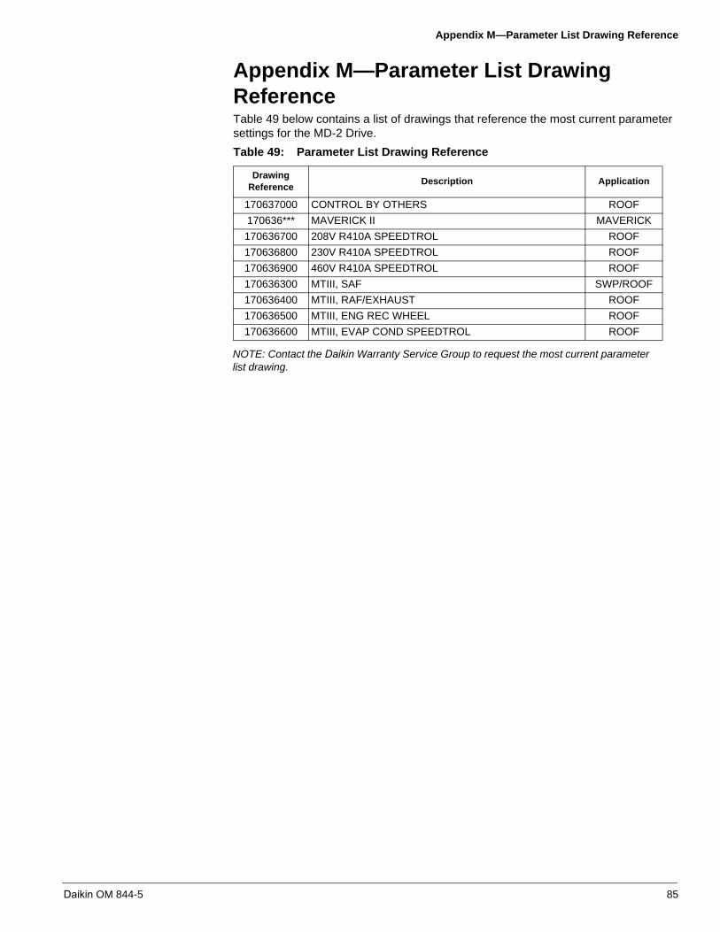
Appendix M—Parameter List Drawing Reference
Appendix M—Parameter List Drawing ReferenceTable 49 below contains a list of drawings that reference the most current parameter settings for the MD-2 Drive.
NOTE: Contact the Daikin Warranty Service Group to request the most current parameter list drawing.
Table 49: Parameter List Drawing Reference
Drawing Reference
Description Application
170637000 CONTROL BY OTHERS ROOF
170636*** MAVERICK II MAVERICK
170636700 208V R410A SPEEDTROL ROOF
170636800 230V R410A SPEEDTROL ROOF
170636900 460V R410A SPEEDTROL ROOF
170636300 MTIII, SAF SWP/ROOF
170636400 MTIII, RAF/EXHAUST ROOF
170636500 MTIII, ENG REC WHEEL ROOF
170636600 MTIII, EVAP COND SPEEDTROL ROOF
Daikin OM 844-5 85

Appendix N—Scaling the Analog Output Through the FM Terminal
Appendix N—Scaling the Analog Output Through the FM TerminalOne analog output is supplied with the drive controller. Terminal FM located on the bottom right terminal strip of the main unit control board is the analog output. FM is a multifunctional programmable analog output supplying an output frequency signal as the factory default.
The FM terminal can output a voltage or current signal:
• When the red switch 2 (SW2) is set to V (voltage), FM outputs a 0-10 VDC signalat 1 mA
• When SW2 is set to I (current), FM outputs a 0-20 mA signal up to 24 VDC
The specific type of signal that the FM terminal will output can be adjusted through parameter . There are 19 different values that can be programmed through parameter that effect what type of signal the FM terminal will output.
Scaling of the analog output through the FM terminal can be done in order to output a specific range of analog signal. The FM terminal will output a default 0-10 VDC signal if SW2 is set to V. The FM terminal will output a 0-20 mA signal if SW2 is set to I. In order to output any range other than the drive default, the following procedure must be carried out.
1. Set SW2 to the desired output, V (Voltage) or I (Current).
2. Change parameter to either 15 or 17 depending on the desired output. Forcurrent output, select 15; for voltage output, select 17.
3. Go to parameter on the VFD display. Press Enter. 100 should be displayed.
4. Disconnect all control wiring at terminal FM on the main unit control board.
Table 50: Analog Output Function Selection (Meter Selection)
ParameterFactory Setting
Value Function Maximum Signal
0
0 Output frequency Maximum frequency (FH)
1 Output current 150% of drive controller’s rated current
2 Speed reference Maximum frequency (FH)
3 DC bus voltage 150% of drive controller’s rated current
4 Output motor voltage 150% of drive controller’s rated current
5 Input power 185% of drive controller’s rated current
6 Output power 185% of drive controller’s rated current
7 Estimated motor torque 250% of rated motor torque
8 Motor torque current Current at 250% of rated motor torque
9 Motor thermal state 100% of motor’s rating
10 Drive controller thermal state 100%
11 DO NOT USE
12 Internal speed reference (after PID) Maximum frequency (FH)
13 VIA input value Maximum input value
14 VIB input value Maximum input value
15 Fixed output – 100% signal (Selection 1 – output current)
16 Fixed output – 50% signal (Selection 1 – output current)
17Fixed output – 100% signal (Selections 0, 2, 3, 4, 5, 6, 7, 8, 9,10, 12, 13, 14, 18)
18 Serial communication data FA51 = 1000
19 DO NOT USE
86 Daikin OM 844-5

Appendix N—Scaling the Analog Output Through the FM Terminal
5. With a digital multimeter measure the voltage or current at the FM terminal. For avoltage measurement, measure across FM and any common (CC) terminal.
6. Use the Up or Down keys to adjust the desired output range while measuring thevalue at the FM terminal with a digital multimeter. Notice that 100 is flashing on thedisplay of the keypad even while voltage or current readings on the digitalmultimeter change.
7. Once the desired range has been set, press Enter on the drive keypad. and100 should flash back and forth on the screen. This means that the desired outputvalue has been locked in or set within the drive controller.
8. Go back to parameter on the drive display. Set it back to the desired type ofoutput (output frequency, output current, etc.).Parameter has an adjustable range of 1 – 1280 and is a unit less parameter. Tofind out what value was set at parameter (to achieve the desired output) insteps 1 through 8, follow steps 9 through 11. This procedure is not necessary, butsometimes beneficial to record the actual value that was set at parameter forfuture reference in case this parameter would happen to be changed, or set backto default at any point in the future.
9. Change parameter to 19. This setting displays the set value at parameter .
10.Go to parameter on the VFD display. Press Enter. The true value that waslocked or set at parameter in steps 1 through 8 should be displayed.
11.Go back to parameter on the drive display. Set it back to the desired type ofoutput (output frequency, output torque, etc.).
Daikin OM 844-5 87

© 2011 Daikin
Daikin Training and Development
Now that you have made an investment in modern, efficient Daikin equipment, its care should be a high priority. For training information on all Daikin HVAC products, please visit us at www.DaikinApplied.com and click on training, or call 540-248-9646 and ask for the Training Department.
Warranty
All Daikin equipment is sold pursuant to its standard terms and conditions of sale, including Limited Product Warranty. Consult your local Daikin Representative for warranty details. Refer to Form 933-43285Y. To find your local Daikin Representative, go to www.DaikinApplied.com.
This document contains the most current product information as of this printing. For the most up-to-date product information, please go to www.DaikinApplied.com.
Daikin Applied800.432.1342www.DaikinApplied.com