Variable-Frequency Fluidic Oscillator Driven by ... · 3 American Institute of Aeronautics and...
12
AIAA 2005-0108 1 American Institute of Aeronautics and Astronautics 43 rd AIAA Aerospace Sciences Meeting & Exhibit Reno, NV January 10 – 14, 2005 Variable-Frequency Fluidic Oscillator Driven by Piezoelectric Devices James W. Gregory * , Ebenezer P. Gnanamanickam † , John P. Sullivan ‡ Purdue University, West Lafayette, IN 47907 and Surya Raghu § Advanced Fluidics Corporation, Ellicott City, MD 21042 This paper describes a new actuator for flow control applications – the piezo-fluidic oscillator. The actuator is a fluidic device based on wall-attachment of a fluid jet, and modulated by piezoelectric devices. The piezo-fluidic oscillator successfully decouples the operating frequency from the flow characteristics of the device. The frequency is specified by an input electrical signal that is independent of pressure, making this actuator ideal for closed-loop control applications. The oscillator exhibits high bandwidth (up to 1.2 kHz), modulation rates up to 100%, and a velocity range reaching sonic conditions. Furthermore, the bi-stable actuator may be operated in a steady state, with momentum flux in one of two desired directions. The piezo-fluidic oscillator may be used in flow control applications where synthetic jets cannot provide enough momentum for control authority. The actuator can also be used as an alternative to traditional aircraft control surfaces while operating in the steady bi-directional mode. This paper details the design and characterization of the piezo-fluidic oscillator. The dynamic response characteristics are evaluated with flow visualization and hot film probe measurements on the output. ** I. Introduction LOW control is a rapidly developing field in applied fluid dynamics, with much of the work focused on actuator development, sensor systems, control logic, and applications. Flow control actuators are devices that are used to enact large-scale changes in a flowfield. Often these changes are focused on improving the performance of a flight vehicle – by delaying stall, reducing drag, enhancing lift, abating noise, reducing emissions, etc. In many flow control situations, unsteady actuation is required for optimal performance. Unsteady actuators are particularly beneficial in closed-loop control applications when the unsteady actuation can be controlled and synchronized with characteristic time scales of the flowfield. Common flow control actuators include synthetic jets, 1 piezoelectric benders for direct excitation, 2,3 powered resonance tubes (also known as Hartmann whistles), 4-6 plasma actuators, 7-11 pulsed jets, 12-14 and steady blowing 15 or suction. 16 These devices and concepts all have inherent strengths and some limitations. Thus, the selection of a flow control actuator often is driven by the requirements of the application. The ideal actuator will have a high frequency bandwidth and direct control by an electrical signal for closed-loop applications. The device should be simple and robust for reliable flight operations – devices with few moving parts are desirable for mechanical reliability. The ideal actuator should also be capable of a large range of flow rates – but only enough for sufficient control authority. Some applications require large flow rates that current actuators cannot * Doctoral Fellow, School of Aeronautics and Astronautics, 315 N. Grant Street, Student Member. † Graduate Research Assistant, School of Aeronautics and Astronautics, 315 N. Grant Street, Student Member. ‡ Professor, School of Aeronautics and Astronautics, 315 N. Grant Street, Senior Member. § President, 4217 Red Bandana Way, Associate Fellow. ** Data animations are available to complement the figures presented in this paper. Contact the first author at [email protected] for access to the animations. Copyright 2005 by James W. Gregory. Published by the American Institute of Aeronautics and Astronautics, Inc., with permission. F
Transcript of Variable-Frequency Fluidic Oscillator Driven by ... · 3 American Institute of Aeronautics and...

AIAA 2005-0108
1 American Institute of Aeronautics and Astronautics
43rd AIAA Aerospace Sciences Meeting & Exhibit Reno, NV January 10 – 14, 2005
Variable-Frequency Fluidic Oscillator Driven by Piezoelectric Devices
James W. Gregory*, Ebenezer P. Gnanamanickam†, John P. Sullivan‡ Purdue University, West Lafayette, IN 47907
and
Surya Raghu§ Advanced Fluidics Corporation, Ellicott City, MD 21042
This paper describes a new actuator for flow control applications – the piezo-fluidic oscillator. The actuator is a fluidic device based on wall-attachment of a fluid jet, and modulated by piezoelectric devices. The piezo-fluidic oscillator successfully decouples the operating frequency from the flow characteristics of the device. The frequency is specified by an input electrical signal that is independent of pressure, making this actuator ideal for closed-loop control applications. The oscillator exhibits high bandwidth (up to 1.2 kHz), modulation rates up to 100%, and a velocity range reaching sonic conditions. Furthermore, the bi-stable actuator may be operated in a steady state, with momentum flux in one of two desired directions. The piezo-fluidic oscillator may be used in flow control applications where synthetic jets cannot provide enough momentum for control authority. The actuator can also be used as an alternative to traditional aircraft control surfaces while operating in the steady bi-directional mode. This paper details the design and characterization of the piezo-fluidic oscillator. The dynamic response characteristics are evaluated with flow visualization and hot film probe measurements on the output.**
I. Introduction LOW control is a rapidly developing field in applied fluid dynamics, with much of the work focused on actuator development, sensor systems, control logic, and applications. Flow control actuators are devices that are used to
enact large-scale changes in a flowfield. Often these changes are focused on improving the performance of a flight vehicle – by delaying stall, reducing drag, enhancing lift, abating noise, reducing emissions, etc. In many flow control situations, unsteady actuation is required for optimal performance. Unsteady actuators are particularly beneficial in closed-loop control applications when the unsteady actuation can be controlled and synchronized with characteristic time scales of the flowfield. Common flow control actuators include synthetic jets,1 piezoelectric benders for direct excitation,2,3 powered resonance tubes (also known as Hartmann whistles),4-6 plasma actuators,7-11 pulsed jets,12-14 and steady blowing15 or suction.16 These devices and concepts all have inherent strengths and some limitations. Thus, the selection of a flow control actuator often is driven by the requirements of the application.
The ideal actuator will have a high frequency bandwidth and direct control by an electrical signal for closed-loop applications. The device should be simple and robust for reliable flight operations – devices with few moving parts are desirable for mechanical reliability. The ideal actuator should also be capable of a large range of flow rates – but only enough for sufficient control authority. Some applications require large flow rates that current actuators cannot
* Doctoral Fellow, School of Aeronautics and Astronautics, 315 N. Grant Street, Student Member. † Graduate Research Assistant, School of Aeronautics and Astronautics, 315 N. Grant Street, Student Member. ‡ Professor, School of Aeronautics and Astronautics, 315 N. Grant Street, Senior Member. § President, 4217 Red Bandana Way, Associate Fellow. ** Data animations are available to complement the figures presented in this paper. Contact the first author at [email protected] for access to the animations. Copyright 2005 by James W. Gregory. Published by the American Institute of Aeronautics and Astronautics, Inc., with permission.
F

2 American Institute of Aeronautics and Astronautics
deliver. Jet thrust vectoring on a flight vehicle is one such example. D.Miller17,18 has specified that the ideal actuator for this application is a pulsed jet that operates at 1 kHz with 100% modulation of the jet at sonic conditions. The focus of this work is development of the piezo-fluidic oscillator towards these design goals.
The fluidic oscillator is a device that generates an oscillating or pulsed jet when supplied with a pressurized fluid. Typical oscillators are bi-stable devices that operate on the principle of wall-attachment. The development history of fluidic oscillators is well documented in published literature.19-22 Fluidic oscillators have been used in many diverse applications, such as windshield washer fluid nozzles,23 flow rate metering,24-26 and flow control applications such as cavity resonance tone suppression,27,28 jet thrust vectoring,29 and enhancement of jet mixing.30,31
The fluidic oscillator operates based on the principle of wall attachment, as shown in Figure 1. When a jet of fluid is adjacent to a wall, entrainment of flow around the jet causes a low-pressure region between the wall and the jet that draws the jet closer to the wall. Thus, the jet will deflect until it has attached to the wall. This principle was observed by Henri Coanda in the 1930’s32 and was later named the Coanda effect.33 The Coanda effect is most commonly encountered in daily life by observing a stream of water from a faucet attach to one’s hand when the two are brought close together. Coanda noticed this phenomenon and applied the principle to steering streams of fluid.
If there are two adjacent walls, such as the symmetric configuration shown in Figure 1, the jet will randomly attach to one wall or the other, based on the randomness of turbulence in the flow. Now, if a pressure pulse is introduced at the control port perpendicular to the jet, the jet will detach from the wall and re-attach to the opposite wall. This occurs through the creation of a separation bubble between the jet and the wall. As more fluid is injected from the control port, the separation bubble enlarges and extends downstream until the jet has entirely separated. The pressure differences and momentum of this separation process then carry the jet over to the opposite wall where it re-attaches.
If the two control ports are set up with a feedback loop system, then the fluidic device can create self-sustained oscillations. This is the typical arrangement of many traditional fluidic oscillators. The disadvantage of this arrangement, however, is that the frequency of oscillations is directly coupled to the flow rate of the device.
For practical flow control problems, it is highly desirable to decouple the operating frequency from the flow rate of the actuator. This is the motivation for developing a piezoelectric-driven fluidic oscillator. This concept has been used in the past to develop a bi-stable pneumatic valve for fluid amplifier technology. The field of fluidics was a significant focus of research efforts in the 1960’s and 70’s. Some of this work concentrated on developing electro-fluidic converters. W.Miller34 originally proposed using piezoelectric devices for fluidic control. He implemented a double-clamped piezoelectric bender to produce acoustic signals for control. As such, the pressures produced by the piezo bender were very low (~ 100 Pa) and even a high-gain fluidic amplifier would have a marginal output. He did demonstrate operation of the device up to 1 kHz. Tesar35 was also an early developer of the concept of external control of a fluidic device. He demonstrated the use of a ferromagnetic filament to guide a jet of air or water in various directions through the Coanda effect. The deflection of the filament was controlled by an adjacent electromagnet. His demonstrations were confined to low frequency deflections (68 Hz) at low pressures. Tesar also briefly suggested the use of filaments with an electrostatic charge, as well as piezoelectric benders for jet control. Taft and Herrick36,37 used a piezoelectric bender to alternately block the input to either one of the two control ports. They operated the device in an unsteady mode, and recorded a flat frequency response up to about 40 Hz with a corresponding phase shift of 90°.36 In later work they demonstrated a flat frequency response of 1 kHz with this same device.37 Chen38,39 developed a mono-stable fluidic injector with a piezo bender on the unstable-side control port. His work focused on developing the device as a fuel injector for natural gas engines. He achieved switch-on response times of 1.65 ms and switch-off response times of 1.85 ms.
This work seeks to develop a piezo-driven fluidic oscillator for use as a flow control actuator. A bi-stable, wall-attachment fluidic oscillator is used along with piezoelectric transducers to achieve oscillatory or steady-state control flow. The piezo-fluidic oscillator successfully decouples the operating frequency from the supply pressure to the device. The actuator can deliver the high mass flow rates that are demanded in some flow control applications. Furthermore, the device is shown to have a wide bandwidth, with partial frequency coverage from 0 to 1.2 kHz.
Figure 1: The principle of wall attachment in a fluidic device, known as the Coanda Effect.
Receptivity Zone

3 American Institute of Aeronautics and Astronautics
II. Piezo-Fluidic Oscillator Design Concepts The main concept of the piezo-fluidic oscillator is the modulation of a fluid jet by piezoelectric transducers.
There are many possible realizations of this concept, which are described as follows. In all cases, the piezoelectric transducer creates a geometrical or fluid dynamic asymmetry in a receptive location in the flowfield. The area of maximum receptivity is just downstream of the power nozzle (as shown in Figure 1), where a traditional fluidic oscillator’s control ports are typically located. The first concept employs piezoelectric buzzers coupled to the control ports in a manner similar to W.Miller’s design.34 The challenge with this design is that a high level of acoustic energy is needed to reach the jet switching threshold of a practical device. This design was attempted in the early stages of this work, but was later abandoned due to insufficient control authority of the piezo buzzers. A similar iteration on this concept would employ synthetic jets at the control ports.
Other concepts employ piezoelectric benders or extenders to change the geometry of the device. A small asymmetry in the power nozzle region can readily cause the jet to switch to the opposite sidewall. A single piezoelectric bender may be positioned on the jet centerline, with the oscillating end pointing either upstream or downstream in the flow. The oscillatory motion of the bender will cause deflection and switching of the jet between the two sidewalls. Another concept is to use piezoelectric benders or extenders in lieu of the control ports. When two extenders are driven 180° out of phase from one another, a geometric asymmetry is created in the shear layer of the jet, causing the jet to attach to the alternate sidewalls. A final concept involves a mono-stable oscillator with only one attachment wall and a piezoelectric bender mounted flush on the attachment wall with the free end pointing upstream into the jet. As the transducer is modulated, the tip will be either flat against the wall, or facing into the flow such that the jet detaches from the wall. In the mono-stable configuration, the unstable location is a free jet that is not attached to an adjacent sidewall.
Two designs were characterized in the work presented here. Both designs rely on a piezoelectric bender mounted on the centerline of the fluidic oscillator nozzle. The first design has the bender tip pointing upstream into the nozzle, as shown in Figure 2. The power nozzle in this geometry is 0.5 mm wide and about 5.5 mm high, with an adjacent wall angle of 30°. The primary disadvantage of this design is the location of the piezoelectric transducer with respect to the flow exit of the device. The protrusion of the bender on the exterior of the oscillator makes it somewhat infeasible for practical applications. One possible solution is to employ a piezo bender with a much shorter length, which typically would decrease the tip deflection range and increase the resonance frequency. The second design, shown in Figure 3, has a similar nozzle geometry, but with the piezo bender mounted upstream of the nozzle with the tip just downstream of the nozzle exit. The nozzle width of the second design is 3 mm wide and 5.5 mm high, with a diffuser half-angle of 15°. The nozzle width was increased over the first design to allow room for the piezo bender to oscillate inside the nozzle. The piezoelectric bender employed in both of these designs is a 4-layer piezoceramic (T434-A4-302 from Piezo Systems, Inc.) that measures 72.4 mm long, 5.1 mm high, and 0.86 mm thick. The specified deflection of the device is ±1050 µm with a resonant frequency of 121 Hz. The piezo bender was driven by a square wave signal from a function generator and amplified by a Lasermetrics voltage amplifier. The amplifier output was passed through an RC circuit to remove the DC bias on the supply. The resulting signal supplied to the piezo bender was a 40 VRMS square wave.
Figure 2: Scale diagram and photograph of the first design, with the piezo device removed for clarity. The piezoelectric bender is positioned in the diffuser, pointing upstream into the flow.

4 American Institute of Aeronautics and Astronautics
Figure 3: Scale diagram and photograph of the second design, with the piezo bender installed. The bender is oriented such that the tip points downstream from the throat, creating a more compact geometry.
III. Measurement Techniques Instrumentation systems involved in characterizing the fluidic oscillator were schlieren imaging, pressure-
sensitive paint (PSP), and hot film probes with a computer data acquisition system. The schlieren and PSP systems were used for flow visualization, while the hot film probes were used for quantitative velocity and frequency measurements. The experimental setup for the PSP and hot film probe techniques is shown in Figure 4.
Figure 4: Experimental setup for the pressure-sensitive paint and hot film probe instrumentation.
The schlieren imaging experimental setup involved the use of a single-pass schlieren system. The illumination source was a strobe light, a General Radio company model 1538-A Strobotac. A neutral density filter was placed in front of the strobe light to control the light intensity passing through the flow and reaching the camera. A 6-inch diameter front-surface concave mirror with a focal length of 5 feet was used to pass the light through the flowfield. A knife-edge was placed at the focal point of the mirror to improve the image contrast. The flowfield was then imaged with a Nikon D100 digital camera. Hydrogen gas was used with the oscillator to enhance the density contrast with ambient air.

5 American Institute of Aeronautics and Astronautics
Pressure-sensitive paint was used to visualize the internal fluid dynamics of the oscillator. Recent work with PSP has extended the frequency response well beyond 20 kHz, such that the current unsteady tests at 50 Hz are fairly straightforward. Bell et al.40 have written a recent review on the PSP technique, and Gregory41 has demonstrated the fast response characteristics of these new paints. The PSP imaging system consisted of a 14-bit CCD camera with a 55-mm f/2.8 Nikon macro lens. A 590-nm long pass filter (Schott Glass OG590) filtered out the excitation light. The paint sample was back-illuminated with an LED array emitting 473-nm light. The illumination from the LED’s was phase-locked with the driving frequency of the piezoelectric transducer. The pulse width was set to 2.5% of the period, and the delay step was 5% of the period. One image was taken at each delay step, producing 20 equally-spaced images throughout the oscillation cycle. Nitrogen was used as the supply gas for the PSP tests, to enable high-contrast visualization of the jet dynamics. Wind-on and wind-off images were used to calculate the intensity ratio presented for visualization.
Hot film probes were positioned at the ends of both attachment walls to measure the velocity and frequency content of the exiting flow. The probes and controller have a specified frequency response of 10 kHz. The data from the probes was recorded through a computer data acquisition system with a sampling rate at least 500 times the driving frequency. Data was simultaneously sampled to record the input signal to the piezoelectric bender, as well as the velocity signals from both hot film probes.
IV. Results and Discussion Results presented in this section involve flow visualization with schlieren and PSP techniques, and velocity
measurements at the exit plane with hot film probes. The velocity data is used to evaluate the response of the piezo-fluidic oscillator at various operating conditions, and to generate frequency maps and bode plots. All of the subsequent data is for the first design (piezo bender pointing upstream as shown in Figure 2), except where noted.
A. Flow Visualization Schlieren imaging was used with the first device to characterize the external flowfield of the piezo-fluidic
oscillator. Two images of the schlieren results are shown in Figure 5, with flow going from left to right. Hydrogen gas was the supply fluid, providing higher-contrast schlieren images due to the high density gradient between the hydrogen and ambient air. These images represent bi-stable operation of the device, with the piezoelectric bender removed for clarity. The fluid jet is attached to top wall for the first image, and then switched to the opposing wall for the second image. These images represent the steady-state operation of the bi-stable device, but the oscillatory operation should be similar as the jet switches between the two stable attachment locations.
Figure 5: Schlieren images of the bi-stable operation of the oscillator, with hydrogen gas used for visualization.
Pressure-sensitive paint was used to visualize the internal fluid dynamics of the unsteady switching process.
Fortunately, this process is repeatable from cycle to cycle, allowing for the use of phase-locking methods in the PSP measurement system. The driving square wave for the piezo bender was used as the phase-locking signal for these measurements. A series of PSP images is shown in Figure 6 to illustrate the switching process, with 1 ms separating each image. For these tests the oscillator was driven at 50 Hz (20 ms period) at a pressure ratio of 1.14 (14.3 kPa gauge). In Figure 6(a), the jet is attached to the lower wall and flowing from left to right, while the piezo bender is

6 American Institute of Aeronautics and Astronautics
near the centerline of the nozzle. As the bender moves downward in (b), it creates a strong adverse pressure gradient in the jet and causes the jet to separate from the attachment wall. Within 1 ms, the jet has reattached to the opposing (upper) wall since this location is more stable than the lower wall in the presence of the piezo bender. In image (d) the jet begins to convect downstream towards the exit of the oscillator (at the edge of the PSP image), and the piezo bender returns to the center location. These images represent one switching process, whereas two switches occur within each oscillation cycle.
(a) (b)
(c) (d)
Figure 6: Series of PSP visualization images with successive delays of 1 ms at an oscillation frequency of 50 Hz. Flow is from left-to-right, and the piezo bender coming from the right is shown in black. When the
bender moves downward, it forces the jet to switch to the top attachment wall.
B. Hot Film Probe Data
1. Velocity Time Histories The exit flow of the piezo-fluidic oscillator was characterized by simultaneous measurement of dual hot film
probes on either side of the device. Anticipated results should show that the two signals are 180° phase shifted from one another, and comparable in velocity magnitude. Temporal velocity data is presented in Figure 7 at (a) 10 Hz and (b) 200 Hz for a pressure ratio of 1.69 (68.9 kPa gauge). The velocity signals for the low frequency case show very little phase delay from the control signal, with very fast rise and decay times. The output of the oscillator at 200 Hz is phase shifted approximately 180° from the low frequency case, but the modulation rate remains fairly high. This operating frequency is near the maximum for this modulation mode and the oscillator soon loses synchronization from the driving signal at higher frequencies. As will be shown later, however, another modulation mode emerges at higher frequencies to maintain operation to over 1 kHz.
7 American Institute of Aeronautics and Astronautics
(a)
(b)
Figure 7: Time history of the oscillator outputs simultaneously measured by hot film probes. (a) 10 Hz, (b) 200 Hz. Pressure ratio is 1.69. Notice the delay in rise and fall times for the 200 Hz condition.
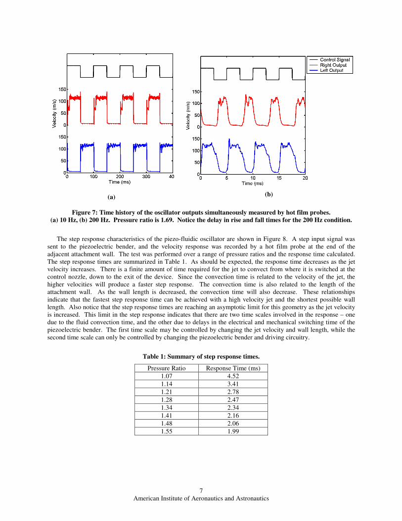
The step response characteristics of the piezo-fluidic oscillator are shown in Figure 8. A step input signal was
sent to the piezoelectric bender, and the velocity response was recorded by a hot film probe at the end of the adjacent attachment wall. The test was performed over a range of pressure ratios and the response time calculated. The step response times are summarized in Table 1. As should be expected, the response time decreases as the jet velocity increases. There is a finite amount of time required for the jet to convect from where it is switched at the control nozzle, down to the exit of the device. Since the convection time is related to the velocity of the jet, the higher velocities will produce a faster step response. The convection time is also related to the length of the attachment wall. As the wall length is decreased, the convection time will also decrease. These relationships indicate that the fastest step response time can be achieved with a high velocity jet and the shortest possible wall length. Also notice that the step response times are reaching an asymptotic limit for this geometry as the jet velocity is increased. This limit in the step response indicates that there are two time scales involved in the response – one due to the fluid convection time, and the other due to delays in the electrical and mechanical switching time of the piezoelectric bender. The first time scale may be controlled by changing the jet velocity and wall length, while the second time scale can only be controlled by changing the piezoelectric bender and driving circuitry.
Table 1: Summary of step response times.
Pressure Ratio Response Time (ms) 1.07 4.52 1.14 3.41 1.21 2.78 1.28 2.47 1.34 2.34 1.41 2.16 1.48 2.06 1.55 1.99

8 American Institute of Aeronautics and Astronautics
Figure 8: Step response of the piezo-fluidic oscillator to the piezo bender.
The response time decreases as the jet velocity increases.
Although the square wave response characteristics of the oscillator begin to diminish at 200 Hz, the device is
able to oscillate at frequencies in the kilohertz range. Figure 9 shows the response of the piezo-fluidic oscillator at a 1.0 kHz driving frequency and a pressure ratio of 1.14 (13.8 kPa gauge). The temporal velocity profile is no longer a square wave, but the jet is clearly modulated at the driving frequency.
The piezo-fluidic oscillator also responds well at very high pressure ratios, as shown in Figure 10. The pressure ratio for this case is 2.15 (115 kPa gauge), creating a sonic jet at the power nozzle. Despite the very high dynamic pressure loads on the piezoelectric bender, it is still able to modulate the jet at low frequencies (5 Hz). Although the jet has not yet been modulated at both high frequency and high pressure, design modifications are underway that should enable this performance level to be attained.
Figure 9: High frequency oscillations at 1.0 kHz and a pressure ratio of 1.14.
Figure 10: Response of the piezo-fluidic oscillator at sonic nozzle conditions. The pressure ratio is 2.15
and the oscillation frequency is 5 Hz.
P/Patm=1.07
P/Patm=1.55

9 American Institute of Aeronautics and Astronautics
2. Frequency Bandwidth While the piezo-fluidic oscillator was operated at a pressure ratio of 1.14, the driving frequency was swept
across a range from 0 to 1200 Hz to evaluate the bandwidth characteristics of the device. The low frequency characteristics (0 – 250 Hz) are shown in Figure 11(a) and the high-bandwidth characteristics are shown in Figure 11(b). Each vertical cross section of the figures is a typical power spectrum generated from the velocity measurements. Note that the primary frequency peak increases linearly with the driving frequency in a 1-to-1 relationship in both figures. For the low frequency range, the first six or seven harmonics are clearly visible and increase linearly with the input frequency. The horizontal and vertical bands correspond to natural resonances of the piezoelectric bender in this flowfield. Figure 11(b) shows that the oscillator has a wide operating range from 0 to 1.2 kHz. There is a small region from 250 to 500 Hz where the piezo bender appears unable to modulate the jet at this pressure. Within this region, the energy in the power spectrum shifts to the horizontal resonance line at 121 Hz. This indicates that the beam is oscillating at its resonant frequency rather than the driving frequency in this range. At approximately 500 Hz, however, the synchronous modulations resume and increase linearly to the upper limit. The second and third harmonics are also visible at the higher driving frequencies.
(a)
(b)
Figure 11: Frequency maps of the piezo-fluidic oscillator performance at a supply pressure ratio of 1.14. The ordinate indicates the driving frequency and the abscissa corresponds to the power spectral density. Figure (a) demonstrates the locked-in behavior of the oscillator in the low frequency range, along with at least the
first six harmonics. Figure (b) shows a short lapse in response from 250 to 500 Hz, but then a resumption of operation with at least the first three harmonics visible in the spectrum.
Magnitude and phase plots may be generated from the hot film probe velocity data. The magnitude values are
calculated from the modulation index (M) which is defined as
max min
max min
V VM
V V−
=+
(1)
where V is the measured velocity. A modulation index of 1 indicates that jet is modulated from zero velocity up to its maximum value. The phase angle is defined as the delay between the control signal and the measured velocity at the exit of the actuator. This phase delay includes any electrical, mechanical, and fluid dynamic delays inherent in the system. Figure 12 shows data for the (a) magnitude and (b) phase for the first design actuator at three operating pressure ratios. First, it is important to point out that the range of operating pressures has little effect on the response characteristics of the piezo-fluidic oscillator across this frequency range. The modulation index remains quite high (80 to 90%) across the entire range. The phase data shows little roll-off until the resonance frequency of the bender is reached (121 Hz). The phase delay is less that 90° until this point, but then quickly rolls off beyond 180°. For some applications this phase delay is of no consequence, but for some closed-loop applications across a range of frequencies, it can be an issue.

10 American Institute of Aeronautics and Astronautics
(a)
(b)
Figure 12: (a) Magnitude and (b) phase plots of the piezo-fluidic oscillator response with the bender facing upstream. At almost all pressures and frequencies the modulation index is greater than 80%. The phase
plots indicate a break point at about 130 Hz, which is near the resonance frequency of the bender.
Data for the second oscillator design (with the piezo bender pointing downstream as shown in Figure 3) is
presented in Figure 13. The modulation index for all three operating pressures is somewhat lower than the results for the first design, typically ranging from 70 – 80%. Furthermore, the modulation of the low speed jet is significantly diminished. This is most likely due to attachment of the jet to the piezo bender rather than the adjacent attachment walls. Thus, the piezo bender serves to impart a small deflection to the jet by directing it, rather than causing it to switch to an opposing wall. There is also more variation in the phase data between the three pressure ratios. The break point varies from 100 Hz for the lowest pressure up to 150 Hz for the highest. In general, the second design (Figure 3) does not perform as well as the first design with the piezo bender pointing upstream (Figure 2).
(a)
(b)
Figure 13: (a) Magnitude and (b) phase plots of the piezo-fluidic oscillator response with the bender facing downstream (with the flow). Note that the modulation index is much lower for all three pressures, when
compared with Figure 12. Also, the break point has shifted to a lower frequency for each pressure.

11 American Institute of Aeronautics and Astronautics
V. Conclusions and Future Work This work has presented the development of the piezo-fluidic oscillator as a new type of flow control actuator.
The oscillator can be driven directly by an electrical signal for closed-loop control applications. The piezo-fluidic oscillator exhibits a fairly high bandwidth with a maximum operating frequency of 1.2 kHz at certain pressures. Over a range of 0 to 250 Hz the oscillation frequency was nearly independent of supply pressure, and operation was maintained well beyond the piezo resonance frequency of 121 Hz. The modulation level remained constant near 90% across this frequency range, and the phase angle didn’t break beyond 90° until the piezo resonance frequency. For oscillations at higher frequencies (500 to 1200 Hz), the jet is most likely modulated in some other manner by the piezo bender, rather than by attachment to the adjacent walls. The piezo-fluidic oscillator was also successfully operated at sonic nozzle conditions at a frequency of 5 Hz. Two designs were evaluated in this work – one with the piezo bender pointed upstream, and the other with the bender pointed downstream. The upstream-pointing bender provided superior modulation characteristics, with a higher modulation index and higher frequency roll-off. The disadvantage of this configuration is that is less compact and not as practical for use as an actuator in flow control applications.
Future work with the piezo-fluidic oscillator will focus on design iterations to improve the operating characteristics. The frequency bandwidth of the oscillator may be increased by selecting a piezo bender with a higher resonance frequency. Also, the length of the attachment walls may be shortened in order to decrease the convection time of the jet, thus increasing the maximum frequency. The ultimate design goal is to create an actuator that will provide a sonic pulsed jet at 100% modulation at 1 kHz. Future work will also involve application of this new actuator to practical flow control problems where high bandwidth and closed-loop control is required.
Acknowledgments The first author gratefully acknowledges funding from the NASA Graduate Student Researcher’s Program,
under the direction of Timothy J. Bencic at Glenn Research Center. The Boeing Company has graciously loaned the CCD camera used for the PSP measurements in this work.
References 1. Glezer, A. and Amitay, M., "Synthetic jets," Annual Review of Fluid Mechanics, Vol. 34, 2002, pp. 503-529. 2. Wiltse, J. M. and Glezer, A., "Manipulation of free shear flows using piezoelectric actuators," Journal of Fluid Mechanics,
Vol. 249, 1993, pp. 261-285. 3. Wiltse, J. M. and Glezer, A., "Direct excitation of small-scale motions in free shear flows," Physics of Fluids, Vol. 10, No.
8, 1998, pp. 2026-2036. 4. Raman, G., Khanafseh, S., Cain, A. B., and Kerschen, E., "Development of high bandwidth powered resonance tube
actuators with feedback control," Journal of Sound and Vibration, Vol. 269, No. 3-5, 2004, pp. 1031-1062. 5. Kastner, J. and Samimy, M., "Development and characterization of Hartmann tube fluidic actuators for high-speed flow
control," AIAA Journal, Vol. 40, No. 10, 2002, pp. 1926-1934. 6. Gregory, J. W. and Sullivan, J. P., "Characterization of Hartmann Tube Flow with Porous Pressure-Sensitive Paint," AIAA
2003-3713, 33rd Fluid Dynamics Conference, American Institute of Aeronautics and Astronautics, Orlando, FL, 2003. 7. Roth, J. R., Sherman, D. M., and Wilkinson, S. P., "Electrohydrodynamic flow control with a glow-discharge surface
plasma," AIAA Journal, Vol. 38, No. 7, 2000, pp. 1166-1172. 8. Stepaniuk, V., Sheverev, V., Otugen, V., Tarau, C., Raman, G., and Soukhomlinov, V., "Sound Attenuation by Glow
Discharge Plasma," AIAA Journal, Vol. 42, No. 3, 2004, pp. 545-550. 9. Artana, G., D'Adamo, J., Leger, L., Moreau, E., and Touchard, G., "Flow control with electrohydrodynamic actuators,"
AIAA Journal, Vol. 40, No. 9, 2002, pp. 1773-1779. 10. Enloe, C. L., McLaughlin, T. E., VanDyken, R. D., Kachner, K. D., Jumper, E. J., and Corke, T. C., "Mechanisms and
Responses of a Single Dielectric Barrier Plasma Actuator: Plasma Morphology," AIAA Journal, Vol. 42, No. 3, 2004, pp. 589-594.
11. Enloe, C. L., McLaughlin, T. E., VanDyken, R. D., Kachner, K. D., Jumper, E. J., Corke, T. C., Post, M., and Haddad, O., "Mechanisms and Responses of a Single Dielectric Barrier Plasma Actuator: Geometric Effects," AIAA Journal, Vol. 42, No. 3, 2004, pp. 595-604.
12. Magill, J. C. and McManus, K. R., "Exploring the feasibility of pulsed jet separation control for aircraft configurations," Journal of Aircraft, Vol. 38, No. 1, 2001, pp. 48-56.
13. M'Closkey, R. T., King, J. M., Cortelezzi, L., and Karagozian, A. R., "The actively controlled jet in crossflow," Journal of Fluid Mechanics, No. 452, 2002, pp. 325-335.
14. Chiekh, M. B., Bera, J. C., Michard, M., Comte-Bellot, G., and Sunyach, M., "Control of a plane jet by fluidic wall pulsing," AIAA Journal, Vol. 41, No. 5, 2003, pp. 972-975.
15. Rao, N. M., Feng, J., Burdisso, R. A., and Ng, W. F., "Experimental demonstration of active flow control to reduce unsteady stator-rotor interaction," AIAA Journal, Vol. 39, No. 3, 2001, pp. 458-464.
12 American Institute of Aeronautics and Astronautics
16. Saric, W. S. and Reed, H. L., "Effect of Suction and Weak Mass Injection on Boundary-Layer Transition," AIAA Journal, Vol. 24, No. 3, 1986, pp. 383-389.
17. Miller, D. N., Yagle, P. J., Bender, E. E., Smith, B. R., and Vermeulen, P. J., "A Computational Investigation of Pulsed Injection into a Confined, Expanding Crossflow," AIAA 2001-3026, 31st Fluid Dynamics Conference and Exhibit, American Institute of Aeronautics and Astronautics, Anaheim, CA, 2001.
18. Yagle, P. J., Miller, D. N., Bender, E. E., Smith, B. R., and Vermeulen, P. J., "A Computational Investigation of Pulsed Ejection," AIAA 2002-3278, 1st Flow Control Conference, American Institute of Aeronautics and Astronautics, St. Louis, MO, 2002.
19. Viets, H., "Flip-flop jet nozzle," AIAA Journal, Vol. 13, No. 10, 1975, pp. 1375-1379. 20. Morris, N. M., An Introduction to Fluid Logic, McGraw-Hill, London, 1973, pp. 58-66. 21. Kirshner, J. M. and Katz, S., Design Theory of Fluidic Components, Academic Press, New York, 1975. 22. Raman, G., Rice, E. J., and Cornelius, D. M., "Evaluation of flip-flop jet nozzles for use as practical excitation devices,"
Journal of Fluids Engineering, Transactions of the ASME, Vol. 116, No. 3, 1994, pp. 508-515. 23. Stouffer, R. D., "Liquid Oscillator Device", U.S. Patent 4,508,267, Issued April 2, 1985. 24. Beale, R. B. and Lawler, M. T., "Development of a wall-attachment fluidic oscillator applied to volume flow metering,"
Flow: Its measurement and control in science and industry., Vol. 1, ISA, Pittsburgh, PA, USA, 1974, pp. 989-996. 25. Beale, Robert Bonine, "The Design of a Liquid Fluidic Reaction Jet System," M.S. Thesis, Department of Mechanical
Engineering, Massachusetts Institute of Technology, Cambridge, MA, 1969. 26. Wang, H., Beck, S. B. M., Priestman, G. H., and Boucher, R. F., "Fluidic pressure pulse transmitting flowmeter," Chemical
Engineering Research & Design, Transactions of the Institute of Chemical Engineers, Part A, Vol. 75, No. A4, 1997, pp. 381-391.
27. Raman, G., Raghu, S., and Bencic, T. J., "Cavity Resonance Suppression Using Miniature Fluidic Oscillators," AIAA 99-1900 (Also NASA/TM-1999-209074), 5th Aeroacoustics Conference, American Institute of Aeronautics and Astronautics, Seattle, WA, 1999.
28. Raghu, S. and Raman, G., "Miniature Fluidic Devices for Flow Control," FEDSM 99-7526, Proceedings of the ASME Fluids Engineering Division Summer Meeting, 1999.
29. Raman, G., Packiarajan, S., Papadopoulos, G., Weissman, C., and Raghu, S., "Jet thrust vectoring using a miniature fluidic oscillator," FEDSM 2001-18057, Proceedings of the ASME Fluids Engineering Division Summer Meeting, Vol. 1, American Society of Mechanical Engineers, New Orleans, LA, 2001, pp. 903-913.
30. Raman, G., Hailye, M., and Rice, E. J., "Flip-flop jet nozzle extended to supersonic flows," AIAA Journal, Vol. 31, No. 6, 1993, pp. 1028-1035.
31. Raman, G., "Using controlled unsteady fluid mass addition to enhance jet mixing," AIAA Journal, Vol. 35, No. 4, 1997, pp. 647-656.
32. Coanda, Henri, "Device for Deflecting a Stream of Elastic Fluid Projected into an Elastic Fluid", United States Patent 2,052,869, Issued September 1, 1936.
33. Metral, A., "Sur un Phenomene de Deviation des Vienes Fluides et Ses Applications (Effet Coanda)," Proceedings of the 5th International Congress for Applied Mechanics, Cambridge, MA, 1939.
34. Miller, W. V., "Experimental Feasibility Study of an Analog Electrical-to-Fluidic Transducer," IEEE Transactions on Industrial Electronics and Control Instrumentation, Vol. IECI-16, No. 1, 1969, pp. 50-58.
35. Tesar, V., "The Guided Jet Principle," Fluidics Quarterly, Vol. 3, No. 4, 1971, pp. 77-99. 36. Taft, C. K. and Herrick, B. M., "A Proportional Electro-Fluidic Pneumatic Valve Design," 20th Anniversary of Fluidics
Symposium, American Society of Mechanical Engineers, New York, 1980, pp. 1-7. 37. Taft, C. K. and Herrick, B. M., "A Proportional Piezoelectric Electro-Fluidic Pneumatic Valve Design," Journal of
Dynamic Systems, Measurement, and Control, Vol. 103, No. 4, 1981, pp. 361-365. 38. Chen, R. and Lucas, G. G., "Investigation into the use of piezo-fluidic combined units as fuel injectors for natural gas
engines," Proceedings of the 1996 International Fall Fuels & Lubricants Meeting & Exposition, Oct 14-17 1996, SAE Special Publications, Vol. 1208, SAE, Warrendale, PA, USA, San Antonio, TX, USA, 1996, pp. 123-134.
39. Chen, R., "Piezo-fluidic gaseous fuel MPI system for natural gas fuelled IC engines," JSME International Journal, Series B: Fluids and Thermal Engineering, Vol. 44, No. 1, 2001, pp. 158-165.
40. Bell, J. H., Schairer, E. T., Hand, L. A., and Mehta, R. D., "Surface pressure measurements using luminescent coatings," Annual Review of Fluid Mechanics, Vol. 33, 2001, pp. 155-206.
41. Gregory, J. W., "Porous Pressure-Sensitive Paint for Measurement of Unsteady Pressures in Turbomachinery," AIAA 2004-0294, 42nd Aerospace Sciences Meeting, American Institute of Aeronautics and Astronautics, Reno, NV, 2004.


![[DESIGN] Piezo-Piezo to Pie](https://static.fdocuments.us/doc/165x107/5571f8bb49795991698df909/design-piezo-piezo-to-pie.jpg)