Variable displacement pump A4VSG Replaces: 01bidonequipment.info/s/REXROTH A4VSG... · Variable...
34
Industrial Hydraulics Electric Drives and Controls Linear Motion and Assembly Technologies Pneumatics Service Automation Mobile Hydraulics Variable displacement pump A4VSG closed circuit Sizes 40...1000 Series 1 and 2 Nominal pressure 350 bar Peak pressure 400 bar Features The axial piston swashplate design variable displacement pump A4VSG is designed for hydrostatic transmission in closed circuit. Flow is proportional to input speed and displacement and is infinitely variable by adjustment of the swashplate. – slot-controlled swashplate design – infinitely variable adjustment of displacement – reversible flow – permissible nominal pressure 350 bar – low noise level – long service life – drive shaft capable of absorbing axial and radial loads – high power/weight ratio – modular design – short control times – through drive and tandem pumps possible – pump swivel angle indicator – installation position optional – operation on HF fluids possible with reduced operating parameters For description of control and regulating devices see separa- te RE sheets RE 92055, RE 92060, RE 92064 RE 92072, RE 92076, RE 92080 Contents Ordering code 2, 3 Hydraulic fluid / Mounting position 4 Technical Data 5 Unit dimensions size 40 6 Unit dimensions size 71 7 Unit dimensions size 125 8 Unit dimensions size 180 9 Unit dimensions size 250 10 Unit dimensions size 355 11 Unit dimensions size 500 12 Unit dimensions size 750 13 Unit dimensions size 1000 14 Summary controls 15, 16, 17 Through drive 18 Unit dimensions for combination pumps 19, 20 Dimensions through drive K31 20 Dimensions through drives K33 and K34 21 Dimensions through drives K35 and K77 22 Dimensions through drives K43 and K51 23 Dimensions through drives K25 and K26 24 Dimensions through drives K27 and K37 25 Dimensions through drives K59, K01 and K52 26 Dimensions through drives K02 and K04 27 Dimensions through drives K06 and K24 28 Dimensions through drives K57 and K68 29 Dimensions through drives K99, size 40...355 30 Dimensions through drives K99, size 500...1000 31 Circuit diagram with auxiliary pump, flushing block and filter 32 Unit dimensions with auxiliary pump, flushing block and filter 33 Mounted and piped auxiliary pump H02 - H05 34 RE 92 100/11.95 1/36 Replaces: 01.95
Transcript of Variable displacement pump A4VSG Replaces: 01bidonequipment.info/s/REXROTH A4VSG... · Variable...
IndustrialHydraulics
Electric Drivesand Controls
Linear Motion andAssembly Technologies Pneumatics
ServiceAutomation
MobileHydraulics
Variable displacement pump A4VSG
closed circuit
Sizes 40...1000Series 1 and 2Nominal pressure 350 barPeak pressure 400 bar
Features
The axial piston swashplate design variable displacement pump
A4VSG is designed for hydrostatic transmission in closed
circuit.
Flow is proportional to input speed and displacement and is
infinitely variable by adjustment of the swashplate.
– slot-controlled swashplate design
– infinitely variable adjustment of displacement
– reversible flow
– permissible nominal pressure 350 bar
– low noise level
– long service life
– drive shaft capable of absorbing axial and radial loads
– high power/weight ratio
– modular design
– short control times
– through drive and tandem pumps possible
– pump swivel angle indicator
– installation position optional
– operation on HF fluids possible with reduced operating
parameters
For description of control and regulating devices see separa-
te RE sheets
RE 92055, RE 92060, RE 92064
RE 92072, RE 92076, RE 92080
Contents
Ordering code 2, 3
Hydraulic fluid / Mounting position 4
Technical Data 5
Unit dimensions size 40 6
Unit dimensions size 71 7
Unit dimensions size 125 8
Unit dimensions size 180 9
Unit dimensions size 250 10
Unit dimensions size 355 11
Unit dimensions size 500 12
Unit dimensions size 750 13
Unit dimensions size 1000 14
Summary controls 15, 16, 17
Through drive 18
Unit dimensions for combination pumps 19, 20
Dimensions through drive K31 20
Dimensions through drives K33 and K34 21
Dimensions through drives K35 and K77 22
Dimensions through drives K43 and K51 23
Dimensions through drives K25 and K26 24
Dimensions through drives K27 and K37 25
Dimensions through drives K59, K01 and K52 26
Dimensions through drives K02 and K04 27
Dimensions through drives K06 and K24 28
Dimensions through drives K57 and K68 29
Dimensions through drives K99, size 40...355 30
Dimensions through drives K99, size 500...1000 31
Circuit diagram with auxiliary pump, flushing block and filter 32
Unit dimensions with auxiliary pump, flushing block and filter 33
Mounted and piped auxiliary pump H02 - H05 34
RE 92 100/11.95 1/36Replaces: 01.95

2/36 Bosch Rexroth AG | Industrial Hydraulics A4VSG | RE 92 100/11.95
Ordering code
E-
A4VS
G
10
22
R
LW1)
P
V
Fluid
Mineral oils (no short code)
HF fluids (except Skydrol)
Axial piston unit
Variable pump, swashplate design, for industrial drives
Operating mode
Pump, closed circuit
Size
Displacement Vg max(cm3) 40 71 125 180 250 355 500 750 1000
Control device
Manual control MA � � � � � � � – – MA
Electric motor control EM � � � � � � � – – EM..
Hydraulic control, flow dependent HM � � � � � � � ❍ ❍ HM..
Hydr. control with servo/ prop. valve HS � � � � � � � � � HS..
Electronic control EO � � � � � � � ❍ ❍ EO..
Hydr. control, pressure dependent HD1) � � � � � � � � ❍ HD..
Press. control, single sided operation DR1) � � � � � � � � ❍ DR..
Power control with hyperbolic curve LR1) � � � � � � � � ❍ LR..N
Hydr. control, distance dependent HW � � � � � � � � ❍ HW
Speed control, secondary control DS � � � � � � � � ❍ DS..
Series
� � – – – – – – –
– – � � � � � � �
Direction of rotation
Viewed on shaft end right
left
bi-directional
Seals
NBR (Nitrile rubber to DIN ISO 1629) with shaft seal FPM
FPM (Fluoride rubber to DIN ISO 1629)
Shaft end
Parallel with key to DIN 6885 P
Splined to DIN 5480 Z
Mounting flange 40 71 125 180 250 355 500 750 1000
ISO 4-hole � � � � � � – – –
ISO 8-hole – – – – – – � � �
Service ports
Ports A,B: SAE at the side (same side), with metric fixing screws
P
Z
B
H
Through drive / tandem pump1. If a second Brueninghaus pump is factory mounted, both ordering codes must be combined with "+" .
Ordering code 1st pump + ordering code 2nd pumpOrdering example: A4VSG 125 EO1/22R – PPB10K339F + A4VSG 71 HM1/10R – PZB10N000N
2. If a gear pump or radial piston pump is factory mounted, please consult us.
1) Bi-directional rotation not always possible, please note separate RE sheets.2) Size 500 only available for DS control, for HS/HS1 see RE 92076� = available ❍ = in preparation – = not available
in prep.
see RE 92072
see RE 92076
see RE 92080
see RE 92060
see RE 92064
see RE 92055
see RE 92068
10

RE 92 100/11.95 | A4VSG Industrial Hydraulics | Bosch Rexroth AG 3/36
Operating mode
Mounting flange
A4VS G / – 10Fluid
Axial piston unit
Size
Control device
Model
Direction of rotation
Seals
Shaft end
Service ports
0
9
Through drive 40 71 125 180 250 355 500 750 1000
Without through drive � � � � � � � � � N00With through drive1) for mounting of axial piston unit, gear pump or radial piston pump
Flange Hub/Shaft to accept
ISO 125, 4-hole Splined shaft 32x2x30x14x9g A4VSO/H/G 40 � � � � � ❍ � ❍ ❍ K31
ISO 140, 4-hole Splined shaft 40x2x30x18x9g A4VSO/H/G 71 – � � � � � � ❍ ❍ K33
ISO 160, 4-hole Splined shaft 50x2x30x24x9g A4VSO/H/G 125 – – � � � ❍ � ❍ ❍ K34
ISO 160, 4-hole Splined shaft 50x2x30x24x9g A4VSO/G 180 – – – � � ❍ � ❍ ❍ K34
ISO 224, 4-hole Splined shaft 60x2x30x28x9g A4VSO/H/G 250 – – – – � ❍ � ❍ ❍ K35
ISO 224, 4-hole Splined shaft 70x3x30x22x9g A4VSO/G 355 – – – – – � ❍ ❍ ❍ K77
ISO 315, 8-hole Splined shaft 80x3x30x25x9g A4VSO/G 500 – – – – – – � � ❍ K43
ISO 400, 8-hole Splined shaft 90x3x30x28x9g A4VSO/G 750 – – – – – – – ❍ ❍ K76
ISO 80, 2-hole Keyed shaft 18 mm dia. A10VSO 18 � � � � � � � ❍ ❍ K51
ISO 100, 2-hole Keyed shaft 22 mm dia. A10VSO 28 � � � � � ❍ ❍ ❍ ❍ K25ISO 100, 2-hole Keyed shaft 25 mm dia. A10VSO 45 � � � � � ❍ � ❍ ❍ K26
ISO 125, 2-hole Keyed shaft 32 mm dia. A10VSO 71 – � � � � � � ❍ ❍ K27
ISO 125, 2-hole Keyed shaft 40 mm dia. A10VSO 100 – – � � � ❍ � ❍ ❍ K37
ISO 180, 4-hole Keyed shaft 45 mm dia. A10VSO 140 – – – ❍ � � � ❍ ❍ K59
82-2 (SAE A, 2-hole) Splined shaft 5/8" 16-4 (SAE A) G2 / GC2/GC3-1X � � � � � � � ❍ ❍ K01
82-2 (SAE A, 2-hole) Splined shaft 3/4" 19-4 (SAE A-B) A10VSO 18 � � � � � � � ❍ ❍ K52
101-2 (SAE B, 2-hole) Splined shaft 7/8" G3, A10VO 28 � � � � � � � � ❍ K02
101-2 (SAE B) Splined shaft 25-4 (SAE B-B) GC4-1X, A10VO 45 ❍ ❍ � ❍ ❍ � ❍ ❍ ❍ K04
101-2 (SAE B) Splined shaft 32-4 (SAE C) GC5-1X ❍ � � ❍ � ❍ ❍ ❍ ❍ K06
127-2 (SAE C) Splined shaft 32-4 (SAE C) A10VO 71 – ❍ ❍ ❍ ❍ ❍ ❍ ❍ ❍ K07
127-2 (SAE C) Splined shaft 38-4 (SAE C-C) GC6-1X, A10VO 100 – – � � � ❍ ❍ ❍ ❍ K24
152-4 (SAE D) Splined shaft 44-4 (SAE D) A10VO 140 – – – ❍ ❍ ❍ ❍ ❍ ❍ K17
63 mm dia. metric, 4-hole Keyed shaft 25 mm dia. R4 � � � ❍ � ❍ ❍ ❍ ❍ K57101-2 (SAE B) 22-4 (SAE B) G4 � � � � � � � � ❍ K68
With through drive, without hub or intermediate flange, with cover closed � � � � � � � � � K99
Auxiliary pump mounted and piped to boost circuit filter
1 auxiliary pump n < 2800 rpm – � � � � � � ❍ ❍ H02
for boost oil circuit n > 2800 rpm � � – – – – – – – H03
1 auxiliary pump for boost and pilot oil n < 2800 rpm – � � – � – – – – H04
circuits combined (only for EO1) n > 2800 rpm � � – – – – – – – H05For mounted auxiliary pumps see RE 90139 (in preparation)
Valves
Without valve block
Valve block SDVB mounted
Filtration
Without filter � � � � � � � � � N
Filter in boost circuit, mounted � � � � � � � ❍ ❍ F
Sandwich plate filter for HS and DS control (see RE 92076 and RE 92055) � � � � � � � 2) – – ZFilter in boost circuit mounted and sandwich plate filter for
� � � � � � � 2) – – UHS and DS controls
4/36 Bosch Rexroth AG | Industrial Hydraulics A4VSG | RE 92 100/11.95
t min = - 25° C Druckflüssigkeitstemperaturbereich t max = + 90° C
- 25° - 10° 10°
20°
30° 50° 70° 90°
- 20° 0° 40° 60° 80° 100°1000
36
16
Temperaturt (° C)
10
1000600400
200
1008060
40
20
15
10
Visk
ositä
t υ (m
m2
/ s)
υ op
t
VG 22
VG 32
VG 46VG 68VG 100
Flushing of the bearingsWith the following operating conditions the bearings should beflushed to ensure correct functioning over a long period:
– with special fluids (not mineral) due to limited lubricity anda narrow operating temperature range
– when operating with mineral oils in limited conditions oftemperature and viscosity
– with vertical installation (drive shaft facing upwards) flushing of thebearings is recommended for lubrication of the front bearing andshaft sealing ring.
Flushing of the bearings is carried out via port "U" in the vicinityof the front flange of the variable pump. The flushing oil flowsthrough the front bearing and out with the pump case drain oil atthe drain port.
The following quantities are required for flushing the varioussizes:
Size 40 71 125 180 250 355 500 750 1000
Qsp L/min 3 4 5 7 10 15 20 30 40
For the given flushing quantities there will be a pressuredifference of approx. 2 bar between port "U" (including fittings)and the case drain oil chamber.
Filtration of fluid (axial piston unit)In order to ensure correct functioning of the unit, a minimum levelof cleanliness to NAS 16389 class 9
SAE class 6ISO/DIS 4406 class 18/15 is necessary.
This is achievable for example with a filter elementType...D 020...(see RE 31278).This gives a filter quotient of
β20 ≥ 100
If a filter for the boost circuit is factory mounted (Orderingcode F ), depending on the size of the axial piston unit thefollowing filters are installed, fitted with opto-electrical cloggingindicator as standard:Sizes 40 and 71: LFBN/HC60G20D1.0/24/VSizes 125, 180 and 250: LFBN/HC110G20D1.0/24/VSize 355: LFBN/HC240G20D1.0/L24/VSize 500: LFBN/HC330G20D1.0/L24/VFor further details see RE 31278.
Temperature range (cf. selection diagram)tmin
= – 25° Ctmax
= + 90° C
Fluid
For extensive information on the selection of fluids and forapplication conditions, please consult our data sheets RE 90220(mineral oils), RE 90221 (environmentally acceptable fluids) orRE 90223 (HF fluids) before proceeding with the design stage.When operating with environmentally acceptable or HF fluidsreduced operating conditions may apply.
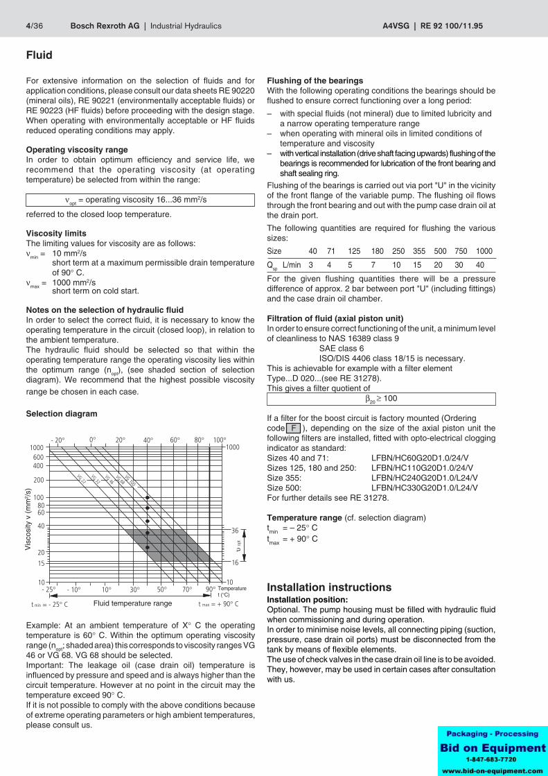
Operating viscosity rangeIn order to obtain optimum efficiency and service life, werecommend that the operating viscosity (at operatingtemperature) be selected from within the range:
νopt = operating viscosity 16...36 mm2/s
referred to the closed loop temperature.
Viscosity limitsThe limiting values for viscosity are as follows:νmin = 10 mm2/s
short term at a maximum permissible drain temperatureof 90° C.
νmax = 1000 mm2/sshort term on cold start.
Notes on the selection of hydraulic fluidIn order to select the correct fluid, it is necessary to know theoperating temperature in the circuit (closed loop), in relation tothe ambient temperature.The hydraulic fluid should be selected so that within theoperating temperature range the operating viscosity lies withinthe optimum range (nopt), (see shaded section of selectiondiagram). We recommend that the highest possible viscosityrange be chosen in each case.
Selection diagram
Installation instructionsInstallation position:Optional. The pump housing must be filled with hydraulic fluidwhen commissioning and during operation.In order to minimise noise levels, all connecting piping (suction,pressure, case drain oil ports) must be disconnected from thetank by means of flexible elements.The use of check valves in the case drain oil line is to be avoided.They, however, may be used in certain cases after consultationwith us.
Example: At an ambient temperature of X° C the operatingtemperature is 60° C. Within the optimum operating viscosityrange (nopt; shaded area) this corresponds to viscosity ranges VG46 or VG 68. VG 68 should be selected.Important: The leakage oil (case drain oil) temperature isinfluenced by pressure and speed and is always higher than thecircuit temperature. However at no point in the circuit may thetemperature exceed 90° C.If it is not possible to comply with the above conditions becauseof extreme operating parameters or high ambient temperatures,please consult us.
Fluid temperature range
Temperaturet (°C)
Vis
cosi
ty v
(m
m2 /
s)
RE 92 100/11.95 | A4VSG Industrial Hydraulics | Bosch Rexroth AG 5/36
± Fax
Fq
X
X/2 X/2
Nenngröße4
3
2
140003000200010000
Drehzahl n (min-1)
Leck
flüss
igke
itsdr
uck
p ab
s (b
ar)
180
125 71 40
500
750
250
355
Table of values (theoretical values, without considering ηmh and ηv; values rounded)
Size 40 71 125 180 250 355 500 750 1000
Displacement Vg max cm3 40 71 125 180 250 355 500 750 1000
Max. speed nmax rpm 3700 3200 2600 2400 2200 2000 1800 1600 1600
Max. flow at nmax Qmax L/min 148 227 325 432 550 710 900 1200 1600
at nE = 1500 rpm L/min 60 107 186 270 375 533 750 1125 1500
Max. power at no max Po max kW 86 132 190 252 321 414 525 700 933
(∆p = 350 bar) at nE = 1500 rpm kW 35 62 109 158 219 311 438 656 875
Max. torque (∆p = 350 bar) at Vg max Tmax Nm 223 395 696 1002 1391 1976 2783 4174 5565
Torque (∆p = 100 bar) at Vg max T Nm 64 113 199 286 398 564 795 1193 1590
Moment of inertia about drive axis J kgm2 0,0049 0,0121 0,03 0,055 0,0959 0,19 0,3325 0,66 1,20
Filling volume L 2 2,5 5 4 10 8 14 19 27
Approx. weight (pump with EO1 control and valve block) m kg 47 60 100 114 214 237 350 500 630
Max. axial force ± Fax max N 600 800 1000 1400 1800 2000 2000 2200 2200
Max. radial force Fq max N 1000 1200 1600 2000 2000 2200 2500 3000 3500
Technical data(applicable for operation with mineral oils)
Operating pressure range - inlet sideRecommended boost pressure pSp ____________________________ 16 barRecommended boost pressure withcommon auxiliary pumpfor boost and pilot oil circuits (EO1) pSp ______________________ 25 bar
Maximum boost pressure – auxiliary pump max. pressure P H max
for MA-, EM-, HM-, HS-, EO-,DS-settings _________________________________ 50 barfor HD-, HW-settings and LR.N- and DR-control ____ 16 bar
Auxiliary pumps - inlet pressureSuction pressure ps min(ν = 10...300 mm2/s) ≥ 0,7 bar absolute
Operating pressure range - outlet side(pressures to DIN 24312)Pressure at port A or BNominal pressure pN _____________________________________________ 350 barPeak pressure pmax _______________________________________________ 400 bar
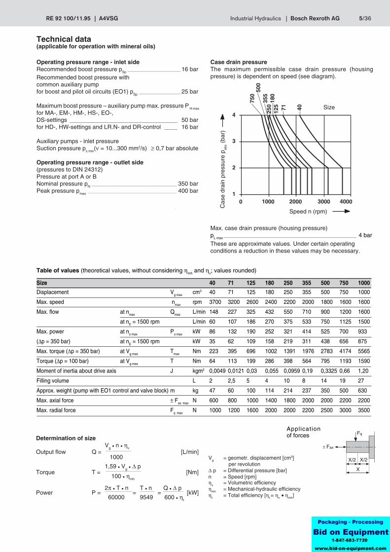
Case drain pressureThe maximum permissible case drain pressure (housingpressure) is dependent on speed (see diagram).
Max. case drain pressure (housing pressure)pL max ______________________________________________________________________ 4 bar
These are approximate values. Under certain operatingconditions a reduction in these values may be necessary.
Vg = geometr. displacement [cm3] per revolution
∆ p = Differential pressure [bar]n = Speed [rpm]ηv = Volumetric efficiencyηmh = Mechanical-hydraulic efficiencyηt = Total efficiency [ηt = ηv • ηmh]
Applicationof forcesDetermination of size
Vg • n • ηvOutput flow Q = [L/min]
1000
1,59 • Vg • ∆ pTorque T = [Nm]
100 • ηmh
2π • T • n T • n Q • ∆ pPower P = = = [kW]
60000 9549 600 • ηt
Size
Speed n (rpm)
Cas
e dr
ain
pres
sure
pab
s (ba
r)
6/36 Bosch Rexroth AG | Industrial Hydraulics A4VSG | RE 92 100/11.95
1,5 5610h9
B
TA
E
UB(A)
R(L)
E
K2 MA
MB
K3
K2
(260/296)
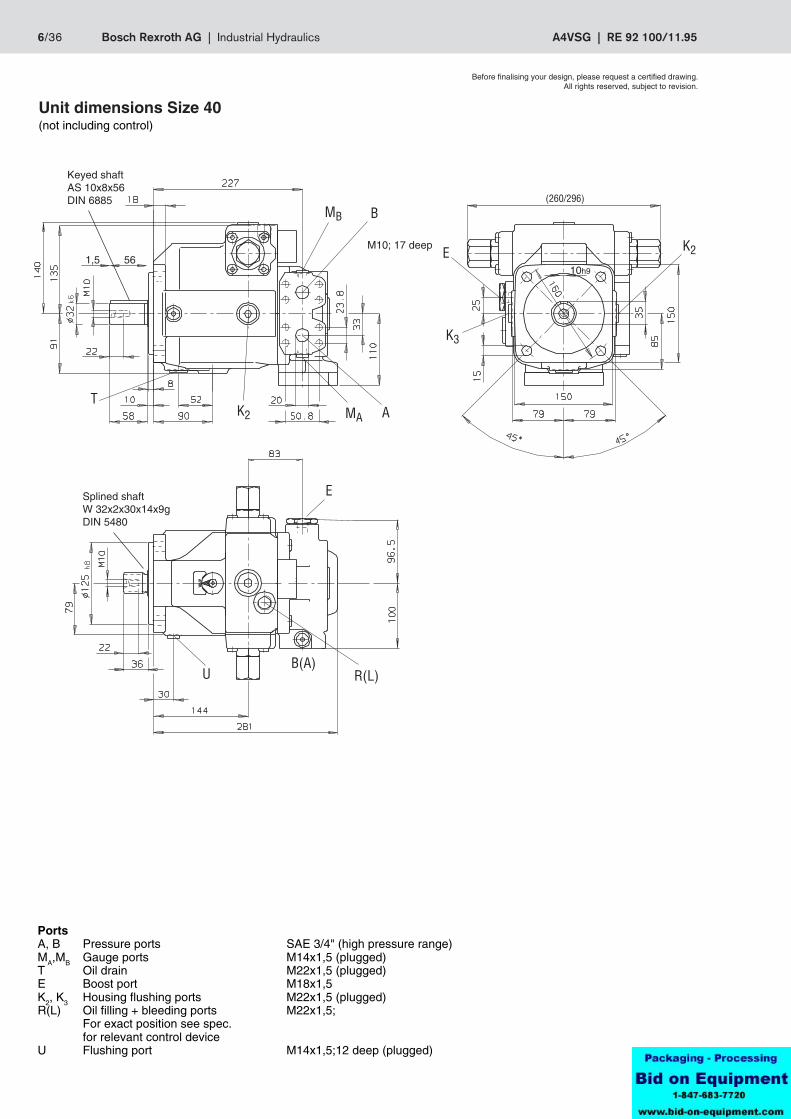
Unit dimensions Size 40(not including control)
PortsA, B Pressure ports SAE 3/4" (high pressure range)MA,MB Gauge ports M14x1,5 (plugged)T Oil drain M22x1,5 (plugged)E Boost port M18x1,5K2, K3 Housing flushing ports M22x1,5 (plugged)R(L) Oil filling + bleeding ports M22x1,5;
For exact position see spec.for relevant control device
U Flushing port M14x1,5;12 deep (plugged)
Keyed shaftAS 10x8x56DIN 6885
M10; 17 deep
Splined shaftW 32x2x30x14x9gDIN 5480
Before finalising your design, please request a certified drawing.All rights reserved, subject to revision.
RE 92 100/11.95 | A4VSG Industrial Hydraulics | Bosch Rexroth AG 7/36
Before finalising your design, please request a certified drawing.All rights reserved, subject to revision.
681,5 12h9
MB B
K2T MA A
E
U B(A)R(L)
E
K3
K2
(296/332)
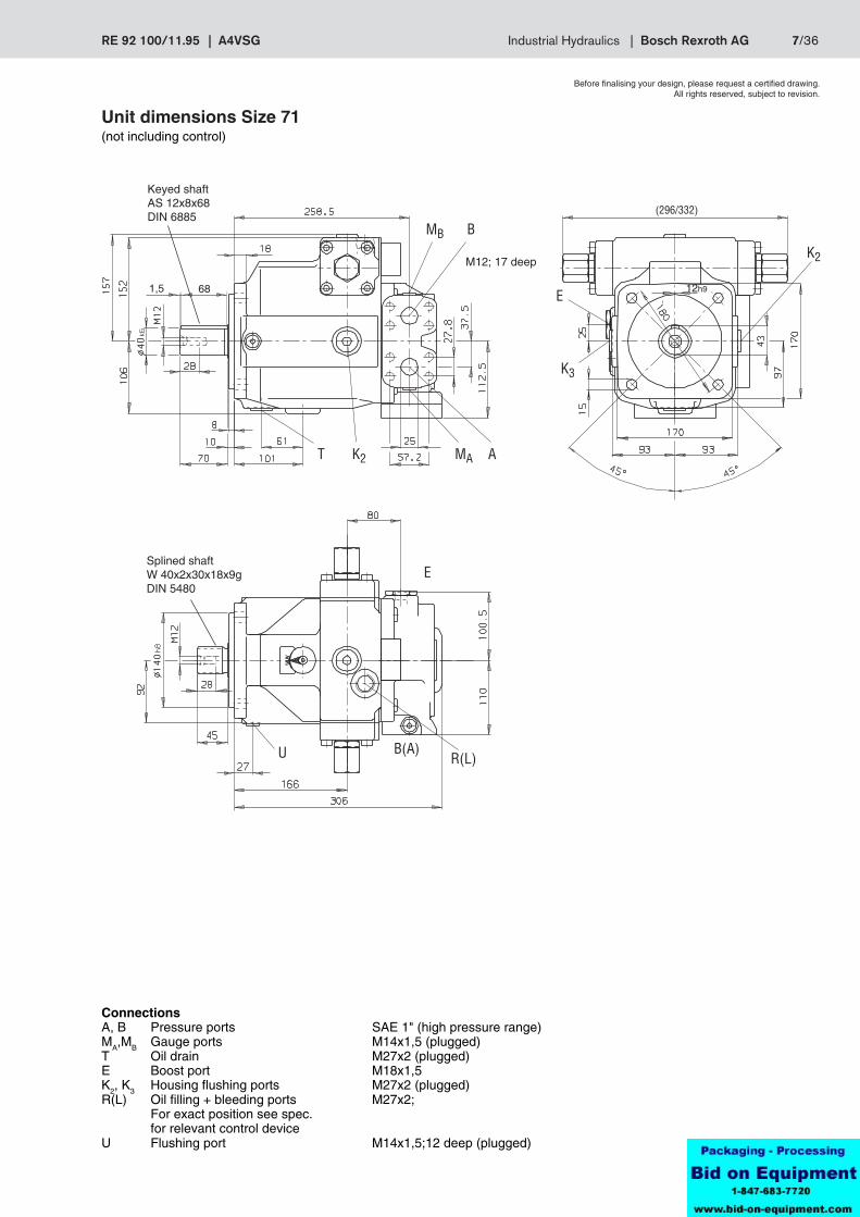
Unit dimensions Size 71(not including control)
Keyed shaftAS 12x8x68DIN 6885
ConnectionsA, B Pressure ports SAE 1" (high pressure range)MA,MB Gauge ports M14x1,5 (plugged)T Oil drain M27x2 (plugged)E Boost port M18x1,5K2, K3 Housing flushing ports M27x2 (plugged)R(L) Oil filling + bleeding ports M27x2;
For exact position see spec.for relevant control device
U Flushing port M14x1,5;12 deep (plugged)
M12; 17 deep
Splined shaftW 40x2x30x18x9gDIN 5480
8/36 Bosch Rexroth AG | Industrial Hydraulics A4VSG | RE 92 100/11.95
801,514h9
MB B
MA AK2T
E
K3
K2
E
U R(L)B(A)
(354/401)
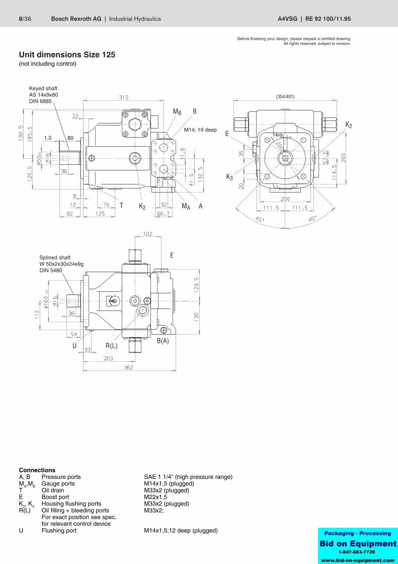
ConnectionsA, B Pressure ports SAE 1 1/4" (high pressure range)MA,MB Gauge ports M14x1,5 (plugged)T Oil drain M33x2 (plugged)E Boost port M22x1,5K2, K3 Housing flushing ports M33x2 (plugged)R(L) Oil filling + bleeding ports M33x2;
For exact position see spec.for relevant control device
U Flushing port M14x1,5;12 deep (plugged)
Before finalising your design, please request a certified drawing.All rights reserved, subject to revision.
Unit dimensions Size 125(not including control)
Keyed shaftAS 14x9x80DIN 6885
M14; 19 deep
Splined shaftW 50x2x30x24x9gDIN 5480
RE 92 100/11.95 | A4VSG Industrial Hydraulics | Bosch Rexroth AG 9/36
801,514h9
29
190,
5
379
MB B
MA AK2T
E
K3
K2
E
U B(A) R(L)
(354/401)
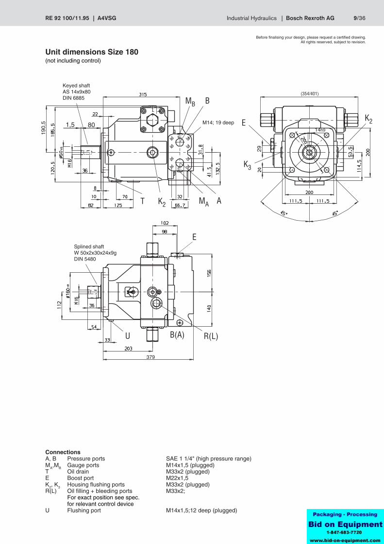
Unit dimensions Size 180(not including control)
Before finalising your design, please request a certified drawing.All rights reserved, subject to revision.
Keyed shaftAS 14x9x80DIN 6885
M14; 19 deep
ConnectionsA, B Pressure ports SAE 1 1/4" (high pressure range)MA,MB Gauge ports M14x1,5 (plugged)T Oil drain M33x2 (plugged)E Boost port M22x1,5K2, K3 Housing flushing ports M33x2 (plugged)R(L) Oil filling + bleeding ports M33x2;
For exact position see spec.for relevant control device
U Flushing port M14x1,5;12 deep (plugged)
Splined shaftW 50x2x30x24x9gDIN 5480
10/36 Bosch Rexroth AG | Industrial Hydraulics A4VSG | RE 92 100/11.95
100318h9
MB B
T K2 MA A
E
K3
K2
E
U R(L)B(A)
(424/485)
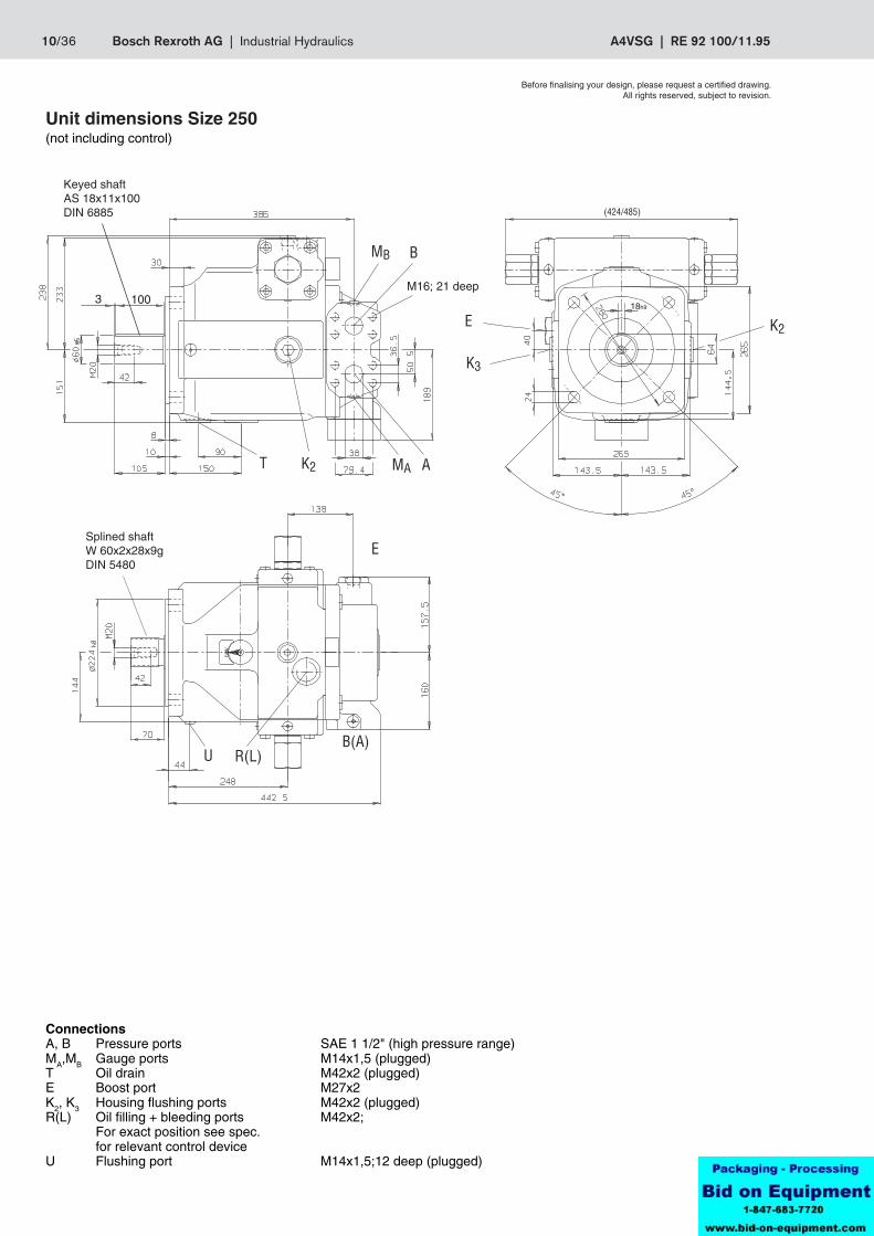
ConnectionsA, B Pressure ports SAE 1 1/2" (high pressure range)MA,MB Gauge ports M14x1,5 (plugged)T Oil drain M42x2 (plugged)E Boost port M27x2K2, K3 Housing flushing ports M42x2 (plugged)R(L) Oil filling + bleeding ports M42x2;
For exact position see spec.for relevant control device
U Flushing port M14x1,5;12 deep (plugged)
Unit dimensions Size 250(not including control)
Keyed shaftAS 18x11x100DIN 6885
Splined shaftW 60x2x28x9gDIN 5480
M16; 21 deep
Before finalising your design, please request a certified drawing.All rights reserved, subject to revision.
RE 92 100/11.95 | A4VSG Industrial Hydraulics | Bosch Rexroth AG 11/36
1004,5 20h9
468
238
MB B
T K2 MA A
E
K3
K2
U R(L) B(A)
(424/485)
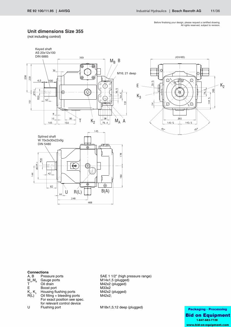
Unit dimensions Size 355(not including control)
Before finalising your design, please request a certified drawing.All rights reserved, subject to revision.
Keyed shaftAS 20x12x100DIN 6885
M16; 21 deep
ConnectionsA, B Pressure ports SAE 1 1/2" (high pressure range)MA,MB Gauge ports M14x1,5 (plugged)T Oil drain M42x2 (plugged)E Boost port M33x2K2, K3 Housing flushing ports M42x2 (plugged)R(L) Oil filling + bleeding ports M42x2;
For exact position see spec.for relevant control device
U Flushing port M18x1,5;12 deep (plugged)
Splined shaftW 70x3x30x22x9gDIN 5480
12/36 Bosch Rexroth AG | Industrial Hydraulics A4VSG | RE 92 100/11.95
1253 22h9
171
130
MB
B
T K2MA A
EK3 K2
U
R(L) B(A)
(510/555)
514
Before finalising your design, please request a certified drawing.All rights reserved, subject to revision.
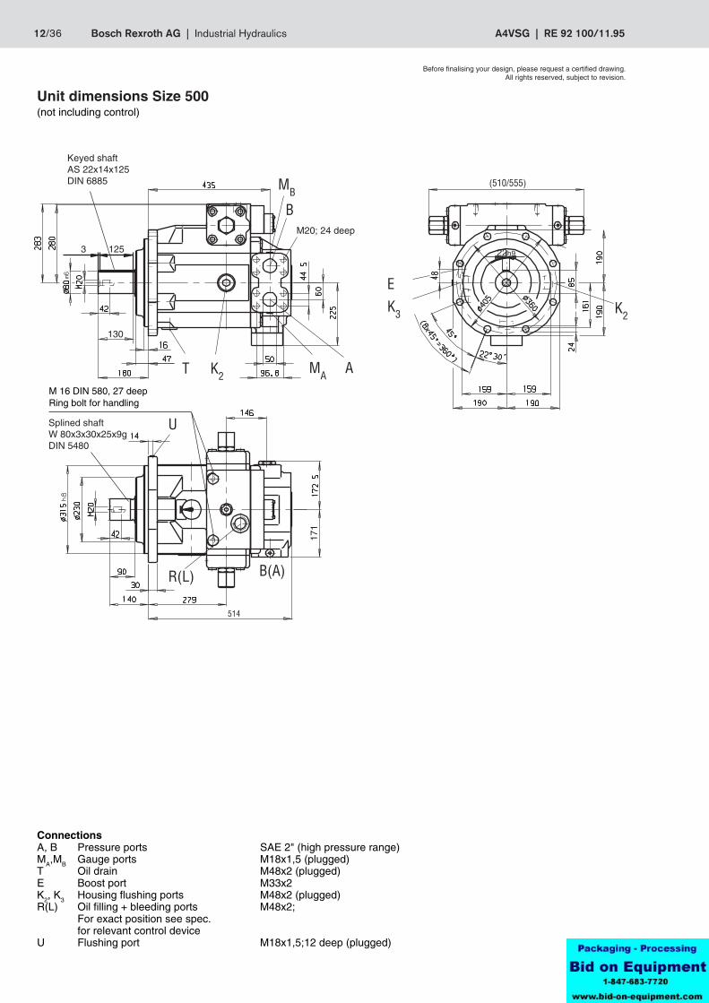
Unit dimensions Size 500(not including control)
Keyed shaftAS 22x14x125DIN 6885
M20; 24 deep
M 16 DIN 580, 27 deepRing bolt for handling
ConnectionsA, B Pressure ports SAE 2" (high pressure range)MA,MB Gauge ports M18x1,5 (plugged)T Oil drain M48x2 (plugged)E Boost port M33x2K2, K3 Housing flushing ports M48x2 (plugged)R(L) Oil filling + bleeding ports M48x2;
For exact position see spec.for relevant control device
U Flushing port M18x1,5;12 deep (plugged)
Splined shaftW 80x3x30x25x9gDIN 5480
RE 92 100/11.95 | A4VSG Industrial Hydraulics | Bosch Rexroth AG 13/36
1254,5
(582/630)
25h9
130
322
MB B
T R(L) MA A
K2 K2
U
R(L) B(A)
478
280
16
177,5
591
210
229
16
+5
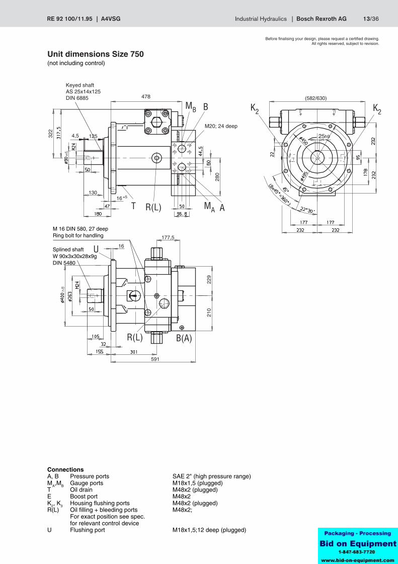
Unit dimensions Size 750(not including control)
Keyed shaftAS 25x14x125DIN 6885
M 16 DIN 580, 27 deepRing bolt for handling
Before finalising your design, please request a certified drawing.All rights reserved, subject to revision.
ConnectionsA, B Pressure ports SAE 2" (high pressure range)MA,MB Gauge ports M18x1,5 (plugged)T Oil drain M48x2 (plugged)E Boost port M48x2K2, K3 Housing flushing ports M48x2 (plugged)R(L) Oil filling + bleeding ports M48x2;
For exact position see spec.for relevant control device
U Flushing port M18x1,5;12 deep (plugged)
M20; 24 deep
Splined shaftW 90x3x30x28x9gDIN 5480
478
14/36 Bosch Rexroth AG | Industrial Hydraulics A4VSG | RE 92 100/11.95
MB1 B
AMA1T R(L)
E
K3
K2
MA2U
R(L)
MB2
B(A)
96.8
Before finalising your design, please request a certified drawing.All rights reserved, subject to revision.
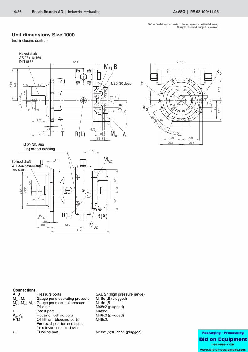
Unit dimensions Size 1000(not including control)
ConnectionsA, B Pressure ports SAE 2" (high pressure range)MA1, MB1 Gauge ports operating pressure M18x1,5 (plugged)MA2, MB2, MP Gauge ports control pressure M14x1,5T Oil drain M48x2 (plugged)E Boost port M48x2K2, K3 Housing flushing ports M48x2 (plugged)R(L) Oil filling + bleeding ports M48x2;
For exact position see spec. for relevant control device
U Flushing port M18x1,5;12 deep (plugged)
Keyed shaftAS 28x16x160DIN 6885
M20; 30 deep
M 20 DIN 580Ring bolt for handling
Splined shaftW 100x3x30x32x9gDIN 5480
RE 92 100/11.95 | A4VSG Industrial Hydraulics | Bosch Rexroth AG 15/36
HW
Vg
Vgmax
Vg
Vgmax
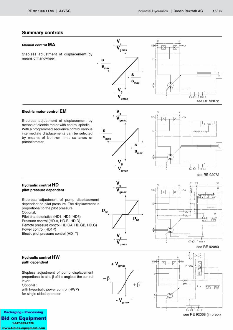
Summary controls
Manual control MA
Stepless adjustment of displacement bymeans of handwheel.
+
-Vg
Vgmax
ssmax
ssmax
-
+
see RE 92072
Electric motor control EM
Stepless adjustment of displacement bymeans of electric motor with control spindle.With a programmed sequence control variousintermediate displacements can be selectedby means of built-on limit switches orpotentiometer.
Vg
Vgmax
+
-Vg
Vgmax
ssmax
+
ssmax
-
see RE 92072
Hydraulic control HDpilot pressure dependent
Stepless adjustment of pump displacementdependent on pilot pressure. The displacement isproportional to the pilot pressure.Optional:Pilot characteristics (HD1, HD2, HD3)Pressure control (HD.A, HD.B, HD.D)Remote pressure control (HD.GA, HD.GB, HD.G)Power control (HD1P)Electr. pilot pressure control (HD1T)
+
-
pSt
pSt
see RE 92080
Hydraulic control HWpath dependent
Stepless adjustment of pump displacementproportional to sine β of the angle of the controllever.Optional :with hyperbolic power control (HWP)for single sided operation
− β+ β
+ Vgmax
- Vgmax
Vg
Vgmax
see RE 92068 (in prep.)
16/36 Bosch Rexroth AG | Industrial Hydraulics A4VSG | RE 92 100/11.95
n2(rpm)
n
n (-)
(+)
+
Vg
Vgmax
-Vg
Vgmax
+ UUmax
; pHD
UUmax
; pHD-
see RE 92076
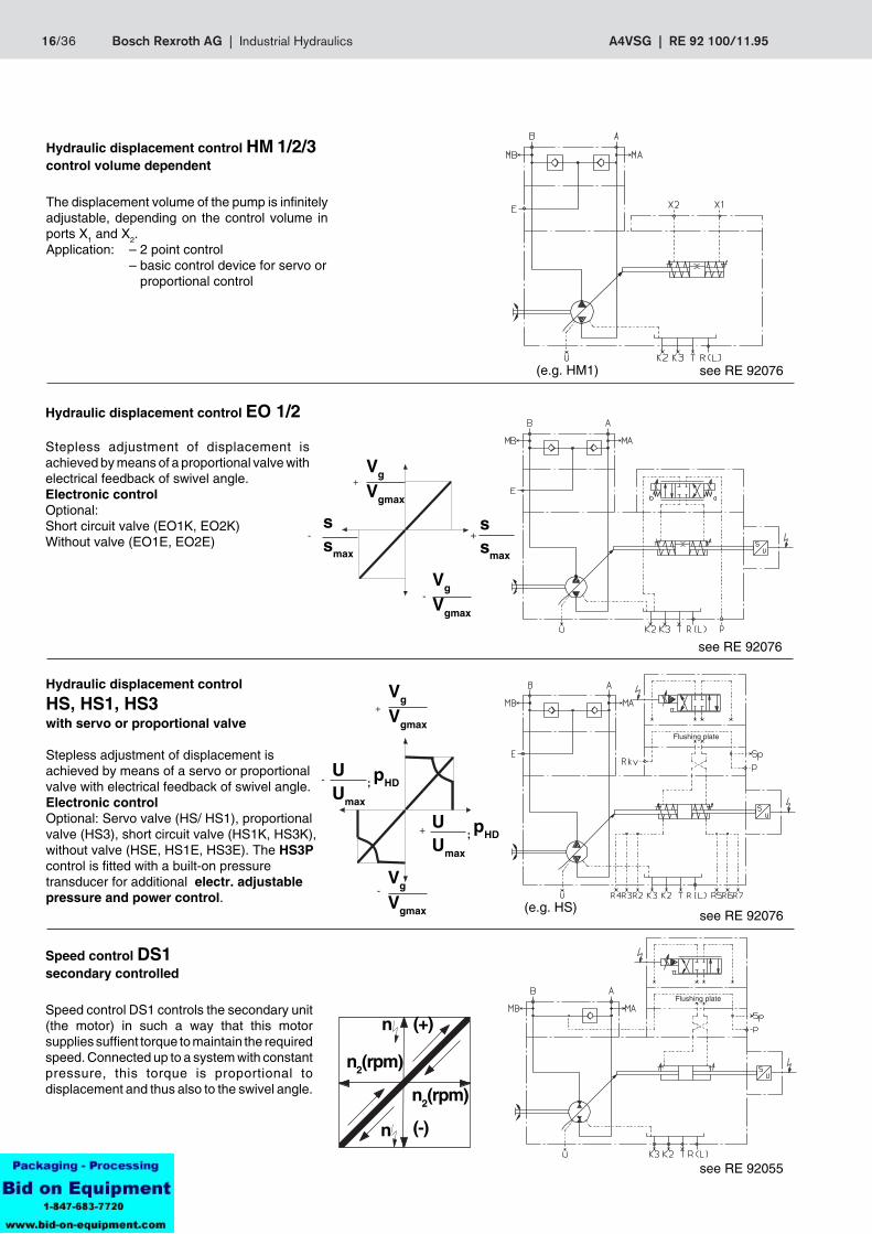
Hydraulic displacement control EO 1/2
Stepless adjustment of displacement isachieved by means of a proportional valve withelectrical feedback of swivel angle.Electronic controlOptional:Short circuit valve (EO1K, EO2K)Without valve (EO1E, EO2E)
see RE 92076
ssmax
+ssmax
-
-Vg
Vgmax
Vg
Vgmax
+
Hydraulic displacement control
HS, HS1, HS3with servo or proportional valve
Stepless adjustment of displacement isachieved by means of a servo or proportionalvalve with electrical feedback of swivel angle.Electronic controlOptional: Servo valve (HS/ HS1), proportionalvalve (HS3), short circuit valve (HS1K, HS3K),without valve (HSE, HS1E, HS3E). The HS3Pcontrol is fitted with a built-on pressuretransducer for additional electr. adjustablepressure and power control.
Speed control DS1secondary controlled
Speed control DS1 controls the secondary unit(the motor) in such a way that this motorsupplies suffient torque to maintain the requiredspeed. Connected up to a system with constantpressure, this torque is proportional todisplacement and thus also to the swivel angle. n2(rpm)
(e.g. HM1)
Hydraulic displacement control HM 1/2/3control volume dependent
The displacement volume of the pump is infinitelyadjustable, depending on the control volume inports X1 and X2.Application: – 2 point control
– basic control device for servo or proportional control
see RE 92055
Flushing plate
see RE 92076(e.g. HS)
Flushing plate
RE 92 100/11.95 | A4VSG Industrial Hydraulics | Bosch Rexroth AG 17/36
K2U K3T R(L)
E
P
B AMB MA
PSt
Rkv
MSt
p
Q
p
Q
p
Q
Vg
Vgmax
pSt
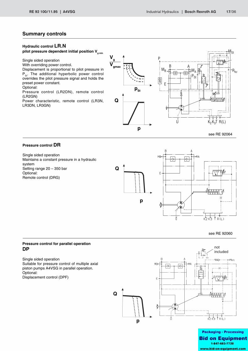
Summary controls
Hydraulic control LR.Npilot pressure dependent initial position Vg min
Single sided operationWith overriding power control.Displacement is proportional to pilot pressure inPSt. The additional hyperbolic power controloverrides the pilot pressure signal and holds thepreset power constant.Optional:Pressure control (LR2DN), remote control(LR2GN)Power characteristic, remote control (LR3N,LR3DN, LR3GN)
see RE 92064
Pressure control DR
Single sided operationMaintains a constant pressure in a hydraulicsystemSetting range 20 – 350 barOptional:Remote control (DRG)
see RE 92060
see RE 92060
Pressure control for parallel operation
DP
Single sided operationSuitable for pressure control of multiple axialpiston pumps A4VSG in parallel operation.Optional:Displacement control (DPF)
notincluded

18/36 Bosch Rexroth AG | Industrial Hydraulics A4VSG | RE 92 100/11.95
m1 m2
l1
l2
MGes
MD1 MD2
MGes
MD1 MD2
Through drive
Axial pistons units A4VSG can be supplied with through drive, asindicated in the ordering code on page 3.It is recommended that no more than three individual pumps arecoupled in series.Included in the supply are:Coupling, fixing screws, seal and an intermediate flange (ifrequired).Combination pumpsTwo or more independent circuits are available to the userwhen combination pumps are fitted.
1. If the combination pump consists of 2 Brueninghaus unitsand if these are to be supplied assembled, the single typecodes should be quoted, joined by "+" .Ordering example:A4VSG 125 EO1/22R – PPB10K339F +A4VSG 71 HM1/10R – PZB10N000N
1.1 If a gear pump or radial piston pump is to be factory fittedas a combination pump, please refer to RE 90139 (inpreparation). This data sheet lists the various pumpcombinations with the type code of the first pump.
2. Assembled and piped auxiliary pumps (see page 32)Depending on the application, various auxiliary pumpsand/or piping are available.Ordering example:A4VSG 125 EO1/22R – PPB10H029FA4VSG with piped auxiliary pump for boost circuit.A4VSG 71EO1/10R – PPB10 H059FA4VSG with one piped auxiliary pump for a common boostand pilot oil circuit, at speeds of n > 2800 rpm.
It is recommended that no more than three individual pumps arecoupled in series.When designing a combination pump using the same sizedpumps (e.g.125 + 125) in combination with control device HD.P,HD.T, HD.U, please consult us.
Permissible bending moment referred to mounting flangeof main pump
m1, m2 [kg] Weight of pumpl1, l2 [mm] Offset of c of g
1 1Tm = m1 • l1 • + m2 • l2 • [Nm]102 102
Permissible through drive torque
Size 40 71 125 180 250 355 500 750
Max. perm. through drive torque at shaft pump 1(pump 1 +pump 2) Ttotal max Nm 446 790 1392 2004 2782 3952 5566 8348
TD1max Nm 223 395 696 1002 1391 1976 2783 4174
TD2max Nm 223 395 696 1002 1391 1976 2783 4174
TD1max Nm 223 395 696 1002 1391 1976 2783 4174
TD2max Nm 223 395 696 1002 1391 1976 2783 4174
1
2
Through torque
Through torque
Splined shaft
Size 40 71 125 180 250 355 500 750
Max. perm. through drive torque at shaft pump 1(pump 1 +pump 2) Ttotal max Nm 380 700 1392 1400 2300 3557 5200 7513
TD1max Nm 223 395 696 1002 1391 1976 2783 4174
TD2max Nm 157 305 696 398 909 1581 2417 3339
TD1max Nm 157 305 696 398 909 1581 2417 3339
TD2max Nm 223 395 696 1002 1391 1976 2783 4174
1
2
Keyed shaft
Size 40 71 125 180 250 355 500 750
Max.bendingTm per Nm 1800 2000 4200 4200 9300 9300 15600 19500
moment
Max. bendingment for dynam. Tm per Nm 180 200 420 420 930 930 1560 1950accel. of10 g 98,1 m/sec2
Weight m kg 47 60 100 114 214 237 350 500
Offset of l1 mm 120 140 170 180 210 220 230 260c of g
Throughtorque
Through torque
totaltotal
1 2
RE 92 100/11.95 | A4VSG Industrial Hydraulics | Bosch Rexroth AG 19/36
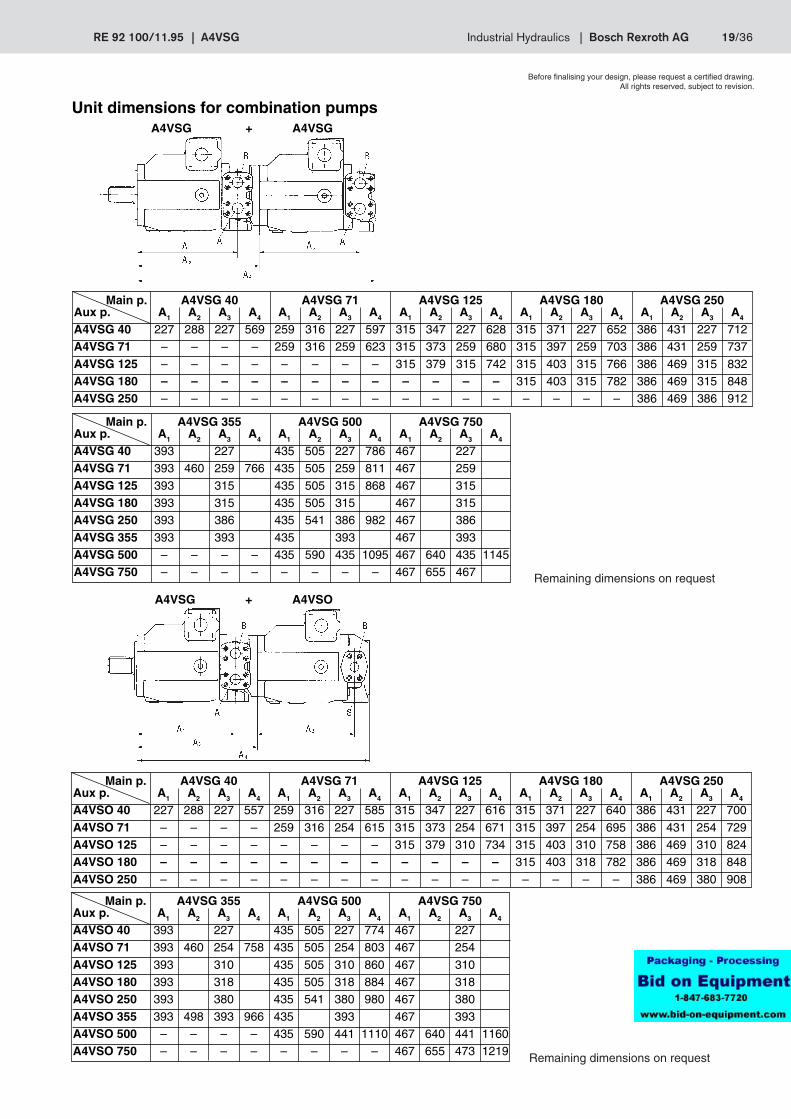
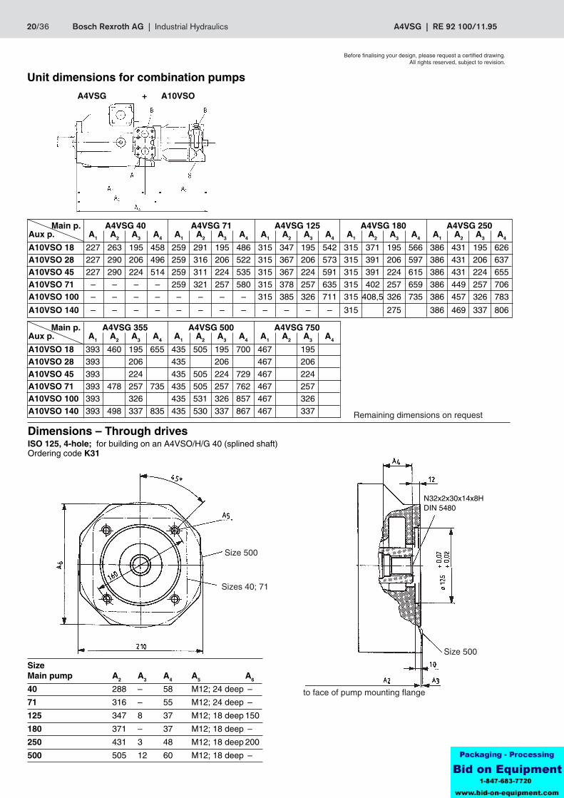
Unit dimensions for combination pumps
Main p. A4VSG 40 A4VSG 71 A4VSG 125 A4VSG 180 A4VSG 250Aux p. A1 A2 A3 A4 A1 A2 A3 A4 A1 A2 A3 A4 A1 A2 A3 A4 A1 A2 A3 A4
A4VSO 40 227 288 227 557 259 316 227 585 315 347 227 616 315 371 227 640 386 431 227 700
A4VSO 71 – – – – 259 316 254 615 315 373 254 671 315 397 254 695 386 431 254 729A4VSO 125 – – – – – – – – 315 379 310 734 315 403 310 758 386 469 310 824A4VSO 180 – – – – – – – – – – – – 315 403 318 782 386 469 318 848
A4VSO 250 – – – – – – – – – – – – – – – – 386 469 380 908
Main p. A4VSG 355 A4VSG 500 A4VSG 750Aux p. A1 A2 A3 A4 A1 A2 A3 A4 A1 A2 A3 A4
A4VSO 40 393 227 435 505 227 774 467 227A4VSO 71 393 460 254 758 435 505 254 803 467 254
A4VSO 125 393 310 435 505 310 860 467 310A4VSO 180 393 318 435 505 318 884 467 318A4VSO 250 393 380 435 541 380 980 467 380
A4VSO 355 393 498 393 966 435 393 467 393A4VSO 500 – – – – 435 590 441 1110 467 640 441 1160A4VSO 750 – – – – – – – – 467 655 473 1219 Remaining dimensions on request
Main p. A4VSG 355 A4VSG 500 A4VSG 750Aux p. A1 A2 A3 A4 A1 A2 A3 A4 A1 A2 A3 A4
A4VSG 40 393 227 435 505 227 786 467 227A4VSG 71 393 460 259 766 435 505 259 811 467 259
A4VSG 125 393 315 435 505 315 868 467 315A4VSG 180 393 315 435 505 315 467 315A4VSG 250 393 386 435 541 386 982 467 386
A4VSG 355 393 393 435 393 467 393A4VSG 500 – – – – 435 590 435 1095 467 640 435 1145A4VSG 750 – – – – – – – – 467 655 467
Main p. A4VSG 40 A4VSG 71 A4VSG 125 A4VSG 180 A4VSG 250Aux p. A1 A2 A3 A4 A1 A2 A3 A4 A1 A2 A3 A4 A1 A2 A3 A4 A1 A2 A3 A4
A4VSG 40 227 288 227 569 259 316 227 597 315 347 227 628 315 371 227 652 386 431 227 712A4VSG 71 – – – – 259 316 259 623 315 373 259 680 315 397 259 703 386 431 259 737
A4VSG 125 – – – – – – – – 315 379 315 742 315 403 315 766 386 469 315 832A4VSG 180 – – – – – – – – – – – – 315 403 315 782 386 469 315 848A4VSG 250 – – – – – – – – – – – – – – – – 386 469 386 912
A4VSG + A4VSG
Remaining dimensions on request
A4VSG + A4VSO
Before finalising your design, please request a certified drawing.All rights reserved, subject to revision.
20/36 Bosch Rexroth AG | Industrial Hydraulics A4VSG | RE 92 100/11.95
Unit dimensions for combination pumps
Before finalising your design, please request a certified drawing.All rights reserved, subject to revision.
A4VSG + A10VSO
Main p. A4VSG 40 A4VSG 71 A4VSG 125 A4VSG 180 A4VSG 250Aux p. A1 A2 A3 A4 A1 A2 A3 A4 A1 A2 A3 A4 A1 A2 A3 A4 A1 A2 A3 A4
A10VSO 18 227 263 195 458 259 291 195 486 315 347 195 542 315 371 195 566 386 431 195 626A10VSO 28 227 290 206 496 259 316 206 522 315 367 206 573 315 391 206 597 386 431 206 637A10VSO 45 227 290 224 514 259 311 224 535 315 367 224 591 315 391 224 615 386 431 224 655
A10VSO 71 – – – – 259 321 257 580 315 378 257 635 315 402 257 659 386 449 257 706A10VSO 100 – – – – – – – – 315 385 326 711 315 408,5 326 735 386 457 326 783
A10VSO 140 – – – – – – – – – – – – 315 275 386 469 337 806
Main p. A4VSG 355 A4VSG 500 A4VSG 750Aux p. A1 A2 A3 A4 A1 A2 A3 A4 A1 A2 A3 A4
A10VSO 18 393 460 195 655 435 505 195 700 467 195A10VSO 28 393 206 435 206 467 206
A10VSO 45 393 224 435 505 224 729 467 224A10VSO 71 393 478 257 735 435 505 257 762 467 257A10VSO 100 393 326 435 531 326 857 467 326
A10VSO 140 393 498 337 835 435 530 337 867 467 337 Remaining dimensions on request
Size 500
Sizes 40; 71
Dimensions – Through drivesISO 125, 4-hole; for building on an A4VSO/H/G 40 (splined shaft)Ordering code K31
SizeMain pump A2 A3 A4 A5 A6
40 288 – 58 M12; 24 deep –
71 316 – 55 M12; 24 deep –
125 347 8 37 M12; 18 deep 150
180 371 – 37 M12; 18 deep –
250 431 3 48 M12; 18 deep 200
500 505 12 60 M12; 18 deep –
to face of pump mounting flange
Size 500
N32x2x30x14x8HDIN 5480
RE 92 100/11.95 | A4VSG Industrial Hydraulics | Bosch Rexroth AG 21/36
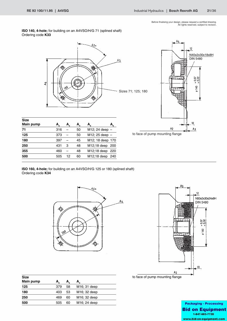
Before finalising your design, please request a certified drawing.All rights reserved, subject to revision.
ISO 140, 4-hole; for building on an A4VSO/H/G 71 (splined shaft)Ordering code K33
Sizes 71; 125; 180
to face of pump mounting flange
ISO 160, 4-hole; for building on an A4VSO/H/G 125 or 180 (splined shaft)Ordering code K34
to face of pump mounting flangeSizeMain pump A2 A3 A4
125 379 58 M16; 31 deep
180 403 53 M16; 32 deep
250 469 60 M16; 32 deep
500 505 60 M16; 24 deep
SizeMain pump A2 A3 A4 A5 A6
71 316 – 50 M12; 24 deep –
125 373 – 50 M12; 25 deep –
180 397 – 45 M12; 18 deep 170
250 431 3 48 M12;18 deep 200
355 460 – 48 M12;18 deep 220
500 505 12 60 M12;18 deep 240
N40x2x30x18x8HDIN 5480
N50x2x30x24x8HDIN 5480
22/36 Bosch Rexroth AG | Industrial Hydraulics A4VSG | RE 92 100/11.95
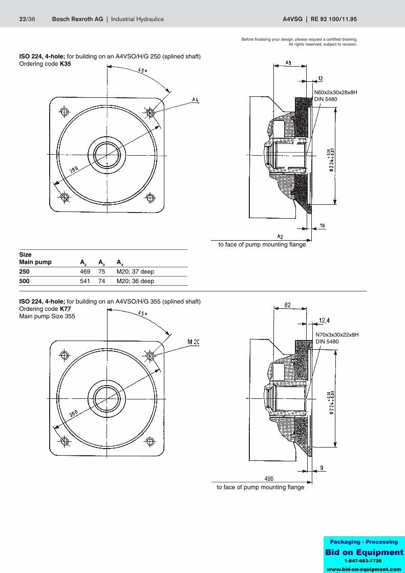
Before finalising your design, please request a certified drawing.All rights reserved, subject to revision.
ISO 224, 4-hole; for building on an A4VSO/H/G 250 (splined shaft)Ordering code K35
to face of pump mounting flange
to face of pump mounting flange
ISO 224, 4-hole; for building on an A4VSO/H/G 355 (splined shaft)Ordering code K77Main pump Size 355
SizeMain pump A2 A3 A4
250 469 75 M20; 37 deep
500 541 74 M20; 36 deep
N60x2x30x28x8HDIN 5480
N70x3x30x22x8HDIN 5480
RE 92 100/11.95 | A4VSG Industrial Hydraulics | Bosch Rexroth AG 23/36
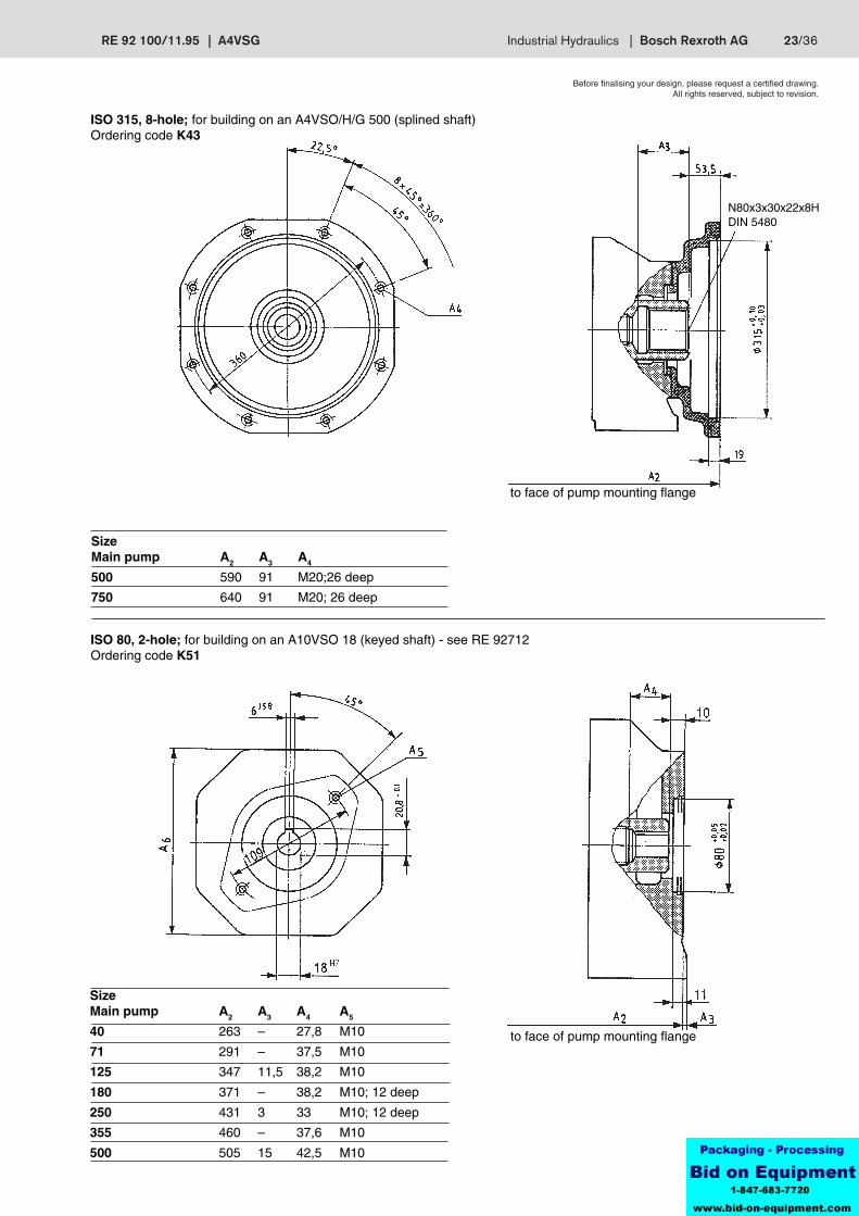
Before finalising your design, please request a certified drawing.All rights reserved, subject to revision.
ISO 315, 8-hole; for building on an A4VSO/H/G 500 (splined shaft)Ordering code K43
to face of pump mounting flange
to face of pump mounting flange
ISO 80, 2-hole; for building on an A10VSO 18 (keyed shaft) - see RE 92712Ordering code K51
SizeMain pump A2 A3 A4
500 590 91 M20;26 deep
750 640 91 M20; 26 deep
SizeMain pump A2 A3 A4 A5
40 263 – 27,8 M10
71 291 – 37,5 M10
125 347 11,5 38,2 M10
180 371 – 38,2 M10; 12 deep
250 431 3 33 M10; 12 deep
355 460 – 37,6 M10
500 505 15 42,5 M10
N80x3x30x22x8HDIN 5480

24/36 Bosch Rexroth AG | Industrial Hydraulics A4VSG | RE 92 100/11.95
Before finalising your design, please request a certified drawing.All rights reserved, subject to revision.
ISO 100, 2-hole; for building on an A10VSO 28 (keyed shaft) - see RE 92711Ordering code K25
ISO 100, 2-hole; for building on an A10VSO 45 (keyed shaft) - see RE 92711Ordering code K26
to face of pump mounting flange
Size 500
Size 40
to face of pump mounting flange
SizeMain pump A2 A3 A4 A5 A6
40 290 – 55 M12; 26 deep –
71 316 2 35 M12; 18 deep 140
125 367 – 37 M12; 15 deep 150
180 391 – 37 M12; 15 deep 150
250 431 3 48 M12; 18 deep 200
Sizes 40; 71
SizeMain pump A2 A3 A4 A5 A6
40 290 – 61 M12; 26 deep –
71 311 – 48 M12; 38 deep –
125 367 – 52 M12; 35 deep 150
180 391 – 52 M12; 20 deep 150
250 431 3 48 M12; 18 deep 200
500 505 12 60 M12; 18 deep 240
RE 92 100/11.95 | A4VSG Industrial Hydraulics | Bosch Rexroth AG 25/36
Before finalising your design, please request a certified drawing.All rights reserved, subject to revision.
to face of pump mounting flange
Size 500
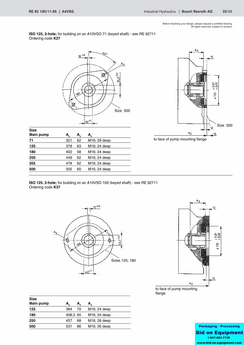
ISO 125, 2-hole; for building on an A10VSO 71 (keyed shaft) - see RE 92711Ordering code K27
Sizes 125; 180
to face of pump mountingflange
ISO 125, 2-hole; for building on an A10VSO 100 (keyed shaft) - see RE 92711Ordering code K37
Size 500
SizeMain pump A2 A3 A4
71 321 62 M16; 29 deep
125 378 63 M16; 24 deep
180 402 58 M16; 24 deep
250 449 62 M16; 24 deep
355 478 62 M16; 24 deep
500 505 60 M16; 24 deep
SizeMain pump A2 A3 A4
125 384 70 M16; 24 deep
180 408,5 65 M16; 24 deep
250 457 68 M16; 26 deep
500 531 86 M16; 26 deep
26/36 Bosch Rexroth AG | Industrial Hydraulics A4VSG | RE 92 100/11.95
Before finalising your design, please request a certified drawing.All rights reserved, subject to revision.
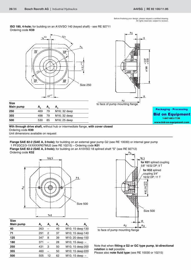
ISO 180, 4-hole; for building on an A10VSO 140 (keyed shaft) - see RE 92711Ordering code K59
Note that when fitting a G2 or GC type pump, bi-directionalrotation is not possible.Please also note fluid type (see RE 10030 or 10215)
to face of pump mounting flange
Size 500
Flange SAE 82-2 (SAE A, 2-hole); for building on an external gear pump G2 (see RE 10030) or internal gear pump 1 PF2GC2/3-1X/XXXXR07MU2 (see RE 10215) – Ordering code K01Flange SAE 82-2 (SAE A, 2-hole); for building on an A10VSO 18 splined shaft "S" (see RE 92712)Ordering code K52
Size 250
to face of pump mounting flange
Wth through drive shaft, without hub or intermediate flange, with cover closedOrdering code K99Unit dimensions available on request
for K01 splined coupling5/8" 16/32 DP; 9 T
for K52 splinedcoupling 3/4"16/32 DP; 11 T
Size 500
SizeMain pump A2 A3 A4
250 469 79 M16; 32 deep
355 498 79 M16; 32 deep
500 530 85 M16; 25 deep
SizeMain pump A2 A3 A4 A5 A6
40 263 – 40 M10; 15 deep 130
71 291 2 37 M10; 15 deep 140
125 347 8 39 M10; 20 deep 150
180 371 – 28 M10; 15 deep –
250 431 3 50 M10; 15 deep 200
355 460 – 50 M10; 15 deep 220
500 505 12 62 M10; 15 deep –
RE 92 100/11.95 | A4VSG Industrial Hydraulics | Bosch Rexroth AG 27/36
Before finalising your design, please request a certified drawing.All rights reserved, subject to revision.
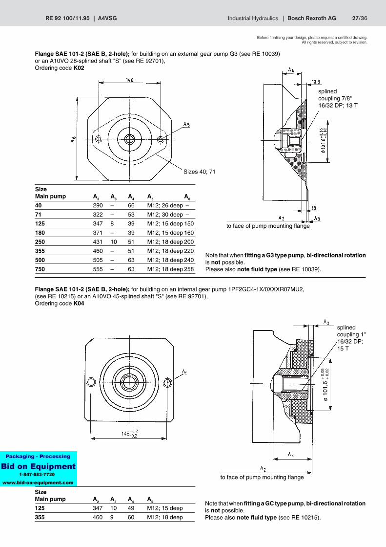
Flange SAE 101-2 (SAE B, 2-hole); for building on an external gear pump G3 (see RE 10039)or an A10VO 28-splined shaft "S" (see RE 92701),Ordering code K02
Note that when fitting a G3 type pump, bi-directional rotationis not possible.Please also note fluid type (see RE 10039).
Sizes 40; 71
to face of pump mounting flange
splinedcoupling 1"16/32 DP;15 T
to face of pump mounting flange
+ 0
,05
+ 0
,02
Flange SAE 101-2 (SAE B, 2-hole); for building on an internal gear pump 1PF2GC4-1X/0XXXR07MU2,(see RE 10215) or an A10VO 45-splined shaft "S" (see RE 92701),Ordering code K04
Note that when fitting a GC type pump, bi-directional rotationis not possible.Please also note fluid type (see RE 10215).
splinedcoupling 7/8"16/32 DP; 13 T
SizeMain pump A2 A3 A4 A5
125 347 10 49 M12; 15 deep
355 460 9 60 M12; 18 deep
SizeMain pump A2 A3 A4 A5 A6
40 290 – 66 M12; 26 deep –
71 322 – 53 M12; 30 deep –
125 347 8 39 M12; 15 deep 150
180 371 – 39 M12; 15 deep 160
250 431 10 51 M12; 18 deep 200
355 460 – 51 M12; 18 deep 220
500 505 – 63 M12; 18 deep 240
750 555 – 63 M12; 18 deep 258
ø 1
01,6

28/36 Bosch Rexroth AG | Industrial Hydraulics A4VSG | RE 92 100/11.95
Before finalising your design, please request a certified drawing.All rights reserved, subject to revision.
Flange SAE 101-2 (SAE B, 2-hole); for building on an internal gear pump 1PF2GC5-1X/0XXXR07MU2,(see RE 10215),Ordering code K06
Note that when fitting a GC type pump, bi-directional rotationis not possible.Please also note fluid type (see RE 10215).
to face of pump mounting flange
splinedcoupling 1 1/2"12/24 DP;17 T
+ 0
,07
+ 0
,02
Size 250
+ 0
,05
+ 0
,02
to face of pump mounting flange
Note that when fitting a GC type pump, bi-directional rotationis not possible.Please also note fluid type (see RE 10215).
Flange SAE 127-2 (SAE C2-hole); for building on an internal gear pump 1PF2GC6-1X/XXXXR07MU2,(see RE 10215), or an A10VO 100 splined shaft "S" (see RE 92701),Ordering code K24
splinedcoupling 1 1/4" 12/24 DP; 14 T
SizeMain pump A2 A3 A4 A5
125 378 9 13,5 M12; 18 deep
SizeMain pump A2 A3 A4 A5
125 377 9 74 M16; 24 deep
180 401 10 72 M16; 24 deep
250 451 10,5 76 M16; 20 deep
ø 1
27ø
101
,6
RE 92 100/11.95 | A4VSG Industrial Hydraulics | Bosch Rexroth AG 29/36
Before finalising your design, please request a certified drawing.All rights reserved, subject to revision.
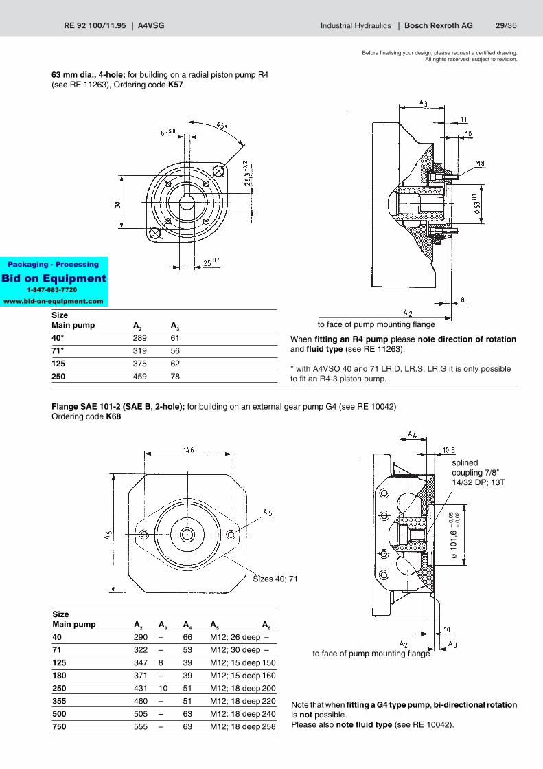
When fitting an R4 pump please note direction of rotationand fluid type (see RE 11263).
* with A4VSO 40 and 71 LR.D, LR.S, LR.G it is only possibleto fit an R4-3 piston pump.
63 mm dia., 4-hole; for building on a radial piston pump R4(see RE 11263), Ordering code K57
to face of pump mounting flange
Flange SAE 101-2 (SAE B, 2-hole); for building on an external gear pump G4 (see RE 10042)Ordering code K68
to face of pump mounting flange
+ 0
,05
+ 0
,02
splinedcoupling 7/8"14/32 DP; 13T
Sizes 40; 71
Note that when fitting a G4 type pump, bi-directional rotationis not possible.Please also note fluid type (see RE 10042).
SizeMain pump A2 A3
40* 289 61
71* 319 56
125 375 62
250 459 78
SizeMain pump A2 A3 A4 A5 A6
40 290 – 66 M12; 26 deep –
71 322 – 53 M12; 30 deep –
125 347 8 39 M12; 15 deep 150
180 371 – 39 M12; 15 deep 160
250 431 10 51 M12; 18 deep 200
355 460 – 51 M12; 18 deep 220
500 505 – 63 M12; 18 deep 240
750 555 – 63 M12; 18 deep 258
ø 1
01,6
30/36 Bosch Rexroth AG | Industrial Hydraulics A4VSG | RE 92 100/11.95
A1 bis Pumpenanflanschfläche
A2
A3
4x A5
A4
A11
A10
A9
A16
A15
A14 A
13A
12
A17
ZahnwellenprofilDIN 5480 s. Tabelle
A6
A8
A7
A6
A7
A8
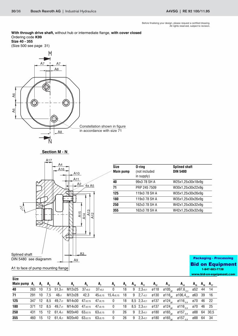
With through drive shaft, without hub or intermediate flange, with cover closedOrdering code K99Size 40 - 355(Size 500 see page 31)
SizeMain pump A1 A2 A3 A4 A5 A6 A7 A8 A9 A10 A11 A12 A13 A14 A15 A16 A17
40 263 10 7,5 51,3±1 M12x25 37±0,2 37±0,2 0 18 9 2,3+0,1 ø118 ø105g6 ø97,6-0,4 ø52 44 14
71 291 10 7,5 48±1 M12x28 42,3 45±0,15 15,4±0,15 18 9 2,7+0,1 ø130 ø116g6 ø106,4-0,4 ø63 39 16
125 347 12 8,5 49,7±1 M14x30 47±0,15 47±0,15 0 18 8,5 2,3+0,1 ø137 ø124g6 ø116-0,4 ø70 46 22
180 371 12 8,5 49,7±1 M14x30 47±0,15 47±0,15 0 18 8,5 2,3+0,1 ø137 ø124g6 ø116-0,4 ø70 46 25
250 431 15 12 61,4±1 M20x40 63±0,15 63±0,15 0 26 9 2,3+0,1 ø180 ø165g6 ø157-0,4 ø88 64 30,5
355 460 15 12 61,4±1 M20x40 63±0,15 63±0,15 0 26 9 2,3+0,1 ø180 ø165g6 ø157-0,4 ø88 64 34
Section M - N
Splined shaftDIN 5480 see diagramm
Size O-ring Splined shaftMain pump (not included DIN 5480
in supply)
40 99x3 78 SH A W25x1,25x30x18x9g
71 PRP 245 7509 W30x1,25x30x22x9g
125 119x3 78 SH A W35x1,25x30x26x9g
180 119x3 78 SH A W35x1,25x30x26x9g
250 162x3 78 SH A W42x1,25x30x32x9g
355 162x3 78 SH A W42x1,25x30x32x9g
Constellation shown in figurein accordance with size 71
A1 to face of pump mounting flange
Before finalising your design, please request a certified drawing.All rights reserved, subject to revision.
RE 92 100/11.95 | A4VSG Industrial Hydraulics | Bosch Rexroth AG 31/36
A8
A1 bis Pumpenanflanschfläche
A2 bis Pumpenanflanschfläche
Zahnwelle DIN 5480s. Tabelle
øA
3
4x A4
A5A6
A7A
9
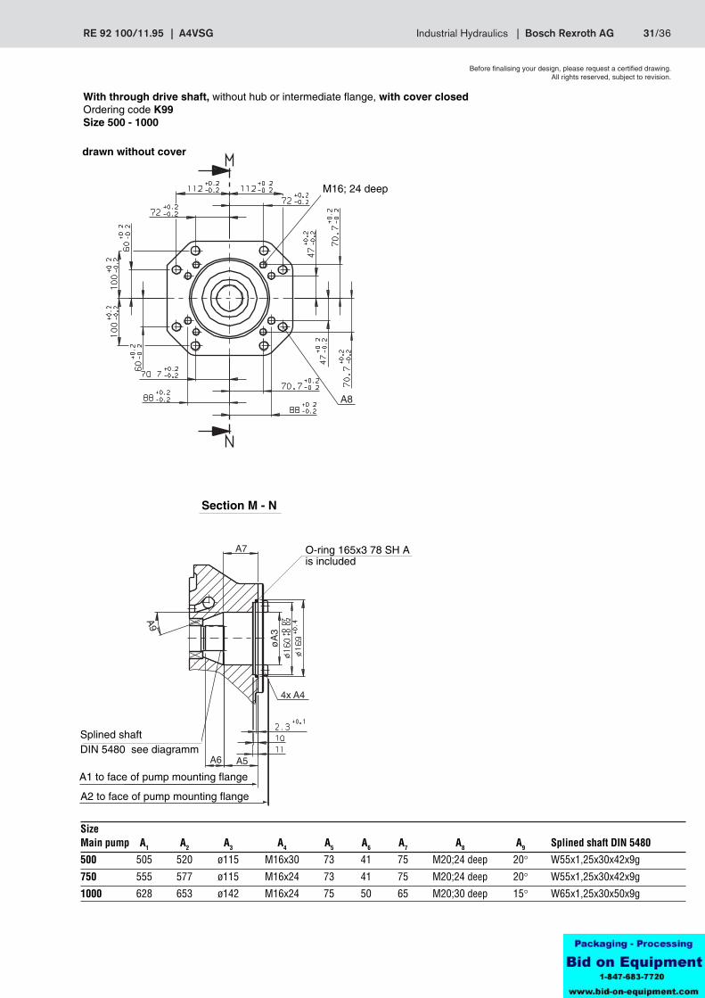
With through drive shaft, without hub or intermediate flange, with cover closedOrdering code K99Size 500 - 1000
drawn without cover
SizeMain pump A1 A2 A3 A4 A5 A6 A7 A8 A9 Splined shaft DIN 5480
500 505 520 ø115 M16x30 73 41 75 M20;24 deep 20° W55x1,25x30x42x9g
750 555 577 ø115 M16x24 73 41 75 M20;24 deep 20° W55x1,25x30x42x9g
1000 628 653 ø142 M16x24 75 50 65 M20;30 deep 15° W65x1,25x30x50x9g
Section M - N
A1 to face of pump mounting flange
Splined shaftDIN 5480 see diagramm
A2 to face of pump mounting flange
Before finalising your design, please request a certified drawing.All rights reserved, subject to revision.
M16; 24 deep
O-ring 165x3 78 SH Ais included
32/36 Bosch Rexroth AG | Industrial Hydraulics A4VSG | RE 92 100/11.95
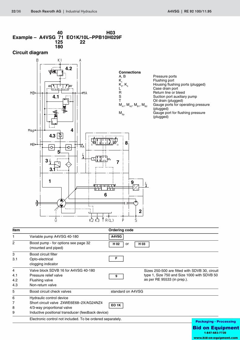
Item Ordering code
1 Variable pump A4VSG 40-180
2 Boost pump - for options see page 32(mounted and piped)
3 Boost circuit filter3.1 Opto-electrical
clogging indicator
4 Valve block SDVB 16 for A4VSG 40-1804.1 Pressure relief valve4.2 Flushing valve4.3 Non-return valve
5 Boost circuit check valves standard on A4VSG
6 Hydraulic control device7 Short circuit valve Z4WE6E68–2X/AG24NZ48 4/3-way proportional valve9 Inductive positional transducer (feedback device)
Electronic control not included. To be ordered separately.
Sizes 250-500 are fitted with SDVB 30, circuittype 1, Size 750 and Size 1000 with SDVB 50as per RE 95533 (in prep.).
or
40 H03Example – A4VSG 71 EO1K/10L–PPB10H029F
125 22180
Circuit diagram
1
4.1
9
3.1
3
5
2
6
7
84.3
4
4.2ConnectionsA, B Pressure portsK1 Flushing portK2, K3 Housing flushing ports (plugged)L Case drain portR Return line or bleedS Suction port auxiliary pumpT Oil drain (plugged)MA1, MA2, MB1, MB2 Gauge ports for operating pressure
(plugged)MSp Gauge port for flushing pressure
(plugged)
A4VSG
H 02 H 03
F
9
EO 1K
RE 92 100/11.95 | A4VSG Industrial Hydraulics | Bosch Rexroth AG 33/36
A15
A7
A9
A6
A8
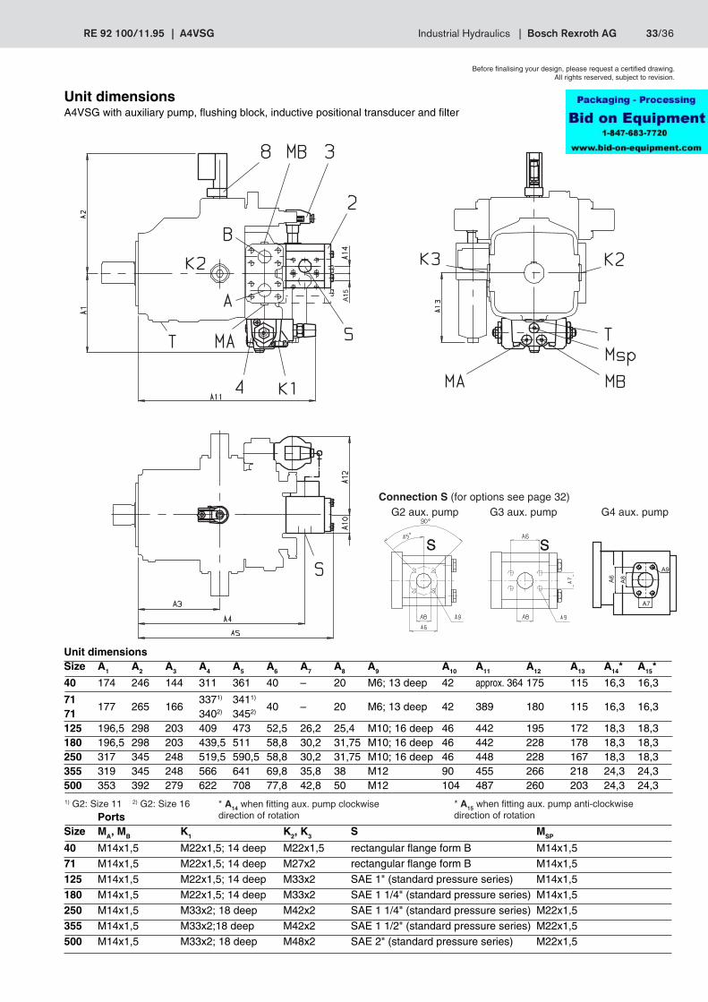
Unit dimensionsA4VSG with auxiliary pump, flushing block, inductive positional transducer and filter
Before finalising your design, please request a certified drawing.All rights reserved, subject to revision.
S
PortsSize MA, MB K1 K2, K3 S MSP
40 M14x1,5 M22x1,5; 14 deep M22x1,5 rectangular flange form B M14x1,5
71 M14x1,5 M22x1,5; 14 deep M27x2 rectangular flange form B M14x1,5
125 M14x1,5 M22x1,5; 14 deep M33x2 SAE 1" (standard pressure series) M14x1,5
180 M14x1,5 M22x1,5; 14 deep M33x2 SAE 1 1/4" (standard pressure series) M14x1,5
250 M14x1,5 M33x2; 18 deep M42x2 SAE 1 1/4" (standard pressure series) M22x1,5
355 M14x1,5 M33x2;18 deep M42x2 SAE 1 1/2" (standard pressure series) M22x1,5
500 M14x1,5 M33x2; 18 deep M48x2 SAE 2" (standard pressure series) M22x1,5
Unit dimensionsSize A1 A2 A3 A4 A5 A6 A7 A8 A9 A10 A11 A12 A13 A14* A15*
40 174 246 144 311 361 40 – 20 M6; 13 deep 42 approx. 364 175 115 16,3 16,3
71 3371) 3411)
177 265 166 40 – 20 M6; 13 deep 42 389 180 115 16,3 16,371 3402) 3452)
125 196,5 298 203 409 473 52,5 26,2 25,4 M10; 16 deep 46 442 195 172 18,3 18,3180 196,5 298 203 439,5 511 58,8 30,2 31,75 M10; 16 deep 46 442 228 178 18,3 18,3250 317 345 248 519,5 590,5 58,8 30,2 31,75 M10; 16 deep 46 448 228 167 18,3 18,3355 319 345 248 566 641 69,8 35,8 38 M12 90 455 266 218 24,3 24,3500 353 392 279 622 708 77,8 42,8 50 M12 104 487 260 203 24,3 24,3
S
* A15 when fitting aux. pump anti-clockwisedirection of rotation
* A14 when fitting aux. pump clockwisedirection of rotation
Connection S (for options see page 32)G2 aux. pump G3 aux. pump G4 aux. pump
1) G2: Size 11 2) G2: Size 16
S S

34/36 Bosch Rexroth AG | Industrial Hydraulics A4VSG | RE 92 100/11.95
Mounted and piped auxiliary pumps H02 - H05
The following auxiliary pumps are supplied mounted and piped:
Size A4VSG 40 71 125 180 250 355 500750 Designation
1 auxiliary pump for boost oil circuit n < 2800 rpm
mounted aux. pump cm3 – G2 16 G3 26 G3 32 G3 38 G4 80 G4 100 H02
1 auxiliary pump for boost oil circuit n > 2800 rpm
mounted aux. pump cm3 G2 11 G2 11 – – – – – – H03
1 auxiliary pump for common boost and pilot oil circuit (only with EO1) n < 2800 rpm
mounted aux. pump cm3 – G2 16 G3 26 – G3 38 – – – H04
1 auxiliary pump for common boost and pilot oil circuit (only with EO1) n > 2800 rpm
mounted aux. pump cm3 G2 11 G2 11 – – – – – – H05
For unit dimensions and technical data see individual data sheets:
G2 - RE 10030
G3 - RE 10039
G4 - RE 10042
= in preparation or on request
Valve block SDVB 16 (for Sizes 40...180), SDVB 30 control type 1 (for Sizes 250...500) andSDVB 50 (for Sizes 750 and 1000) see RE 95533 (in preparation)