VARIABLE DISPLACEMENT AXIAL PISTON PUMPS Page FEATURES.....1
56
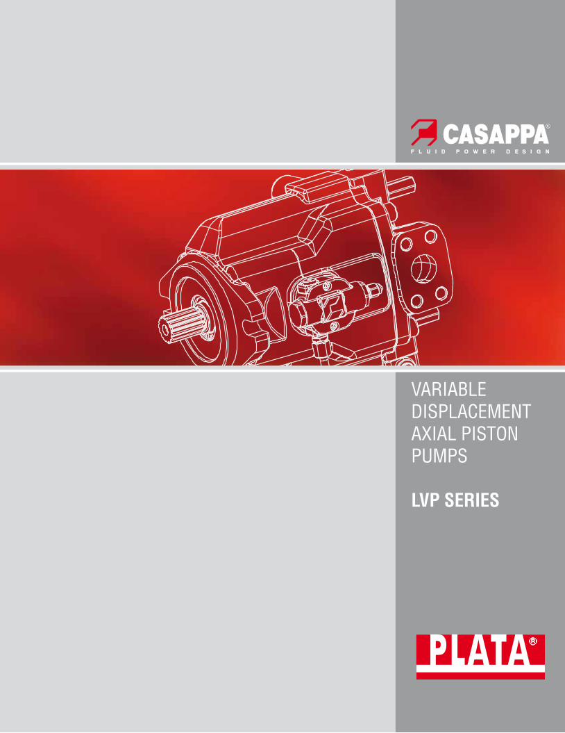
VARIABLE DISPLACEMENT AXIAL PISTON PUMPS LVP SERIES
Transcript of VARIABLE DISPLACEMENT AXIAL PISTON PUMPS Page FEATURES.....1
Edition: 04/04.2013LVP 04 T A Replaces: LVP 03 T A
VARIABLE DISPLACEMENT AXIAL PISTON PUMPS
LVP SERIES
Headquarters:
CASAPPA S.p.A.Via Balestrieri, 1
43044 Lemignano di Collecchio
Parma (Italy)
Tel. (+39) 0521 30 41 11
Fax (+39) 0521 80 46 00
IP VideoconferencingE-mail: [email protected]
Section Page
FEATURES ......................................................................................................................... 1
MOUNTING POSITIONS ......................................................................................................... 3
TECHNICAL DATA ................................................................................................................ 4
DISPLACEMENT SETTING CENTER OF GRAVITY ............................................................................................................ 8
OPERATING CURVES ........................................................................................................... 9
SINGLE PUMPS - DIMENSIONS .............................................................................................. 13
DRIVE SHAFTS .................................................................................................................. 19
MOUNTING FLANGES .......................................................................................................... 21
PORTS SIZES ................................................................................................................... 23
REGULATORS ................................................................................................................... 26
MULTIPLE PUMPS ............................................................................................................. 41
HOW TO ORDER ................................................................................................................ 50
INDEX
O Modi!cation from former edition.
04/0
4.20
13R
epla
ces:
03/
01.2
007
DCAT037-001 ID02 1
LVP
Variable displacement axial piston pumps with swash plate design. LVP pumps are ideally suited for medium and high pressure open circuit applications. They are available with a wide range of control options to regulate the pumps displacement. The drive shaft is designed for both radial and axial loads. The pumps are also available with a through drive option to have multiple pumps able to supply several hydraulic systems.
DISPLACEMENTSFrom 14 cm3/rev (0.85 in3/rev)To 87,9 cm3/rev (5.36 in3/rev)
PRESSUREMax. continuous 280 bar (4060 psi)Max. intermittent 315 bar (4568 psi)Max. peak 350 bar (5075 psi)
SPEEDMax. 3000 min-1
APPLICATIONMedium, high pressure
SECTORMobile/Industrial
FEATURES
TIPICAL APPLICATIONS�z Wheel Loaders-Backhoe Loaders
�z Midi-Excavators
�z Asphalt Pavers
�z Telehandlers
�z Windmills-Green Energy
�z Hydraulic Presses
�z Hydraulic Power Units
�z Injection Molding Machines
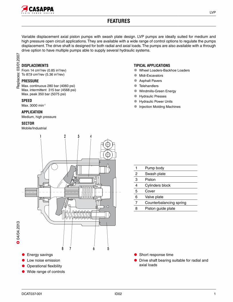
1 Pump body2 Swash plate3 Piston4 Cylinders block5 Cover6 Valve plate7 Counterbalancing spring8 Piston guide plate
�z Energy savings
�z Low noise emission
�z Operational flexibility
�z Wide range of controls
�z Short response time
�z Drive shaft bearing suitable for radial and axial loads
Rep
lace
s: 0
3/01
.200
7O
04/
04.2
013
2 ID02 DCAT037-001
LVP
GENERAL INFORMATION / INSTRUCTIONS
STORAGENo problem in case of temperature down to -40°C (-40°F). Below -40°C (-40°F) please consult our technical-sales de-partment.
STARTING UPWe strongly recommend to warm up the oil before running the machine. If this is not possible, the warm up of the oil and of the pump should be carried out following these instructions:• Start the pump in stand-by condition at minimum speed. Keep this working condition until the pump case reaches -20°C (-4°F)• Increase slowly the displacement. Max pressure permitted: 50 bar (725 psi). The maximum permitted speed is strictly connected to the layout of the inlet circuit; check that there is no cavitation before increasing the speed.• Keep this working condition until the oil temperature in the whole system is -10°C (14°F).• Maximum pressure can be achieved from now on.• Always check the outlet flow to prevent cavitation damage.
All the temperature are referred to oil with viscosity ISO VG 32 according to DIN 51 519.
SUGGESTIONSTo prevent cavitation at low temperature we suggest:• To warm up the tank• To pressurize the tank• To oversize the inlet hose
FOR VERY LOW TEMPERATURE
DIRECTION OF ROTATIONClockwise or anti-clockwise defined looking at the drive shaft.
HYDRAULIC FLUIDMineral oil based hydraulic fluid conforming to DIN 51524, fire resistant fluids and biodegradable fluids according to the technical data shown in the tables at pages 4 ÷ 6. The system should be designed to prevent aeration of the hydraulic fluid.
FLUID VISCOSITYThe fluid viscosity range for optimal use of LVP pump is betwe-en 15 and 35 cSt (77 and 163 SSU).Functional limit conditions are:max.: 1500 cSt (6818 SSU) at start up at -25 °C (-13 °F) with straight and short inlet line.min.: 10 mm2/s (58 SSU) at maximum temperature of 110 °C (230 °F)
FILTRATIONTo ensure the optimal performance and the maximum life to the pump, the hydraulic fluid must have and maintain a fluid conta-mination within the values shown in the table below.
Working pressure bar (psi)
∆p < 140 (2030)
140 < ∆p < 210 (2030) (3045)
∆p > 210 (3045)
Contamination class NAS 1638 9 8 7
Contamination class ISO 4406:1999
20/18/15 19/17/14 18/16/13
Achieved with filter ßx(c) ≥75 according to ISO 16889
10 μm 10 μm 10 μm
Casappa recommends to use its own production filters:
INSTALLATIONCheck that the maximum coupling eccentricity stays within 0,25 mm (0.0098 in) to reduce shaft loads due to misalignment. It is advised to use a flexible coupling suitable to absorb eventual rotational shocks. For applications with axial and radial loads exceeding published standards, consult our sales department. The direction of rotation of the pump must agree with the prime mover rotation. Before installation, the case of the pump must be filled with fluid.
LINESThe lines must have a major diameter which is at least as large as the diameter of pump ports, and must be perfectly sealed. To reduce loss of power, the lines should be as short as possi-ble, reducing the sources of hydraulic resistance (elbow, thrott-ling, gate valves, etc.) to a minimum. A length of flexible tubing is recommended to reduce the transmission of vibrations.
Before connecting the lines, remove any plug and make sure that the lines are perfectly clean. Check that the drain line is dimensioned in a way to guarantee a case pressure lower than 1,5 bar (22 psi) absolute. The drain line must be connected directly (no filter, no valves, no oil cooler) to the tank and must terminate below the oil level. Check that the dimensions of the suction line guarantee a pressure equal or superior to 0,8 bar (24 in Hg). Inlet pressure less than 0,8 bar (24 in Hg) could cause an increase of noise emission, the decrease of the pump performances and a reduction of its life expectancy.
STARTING UPCheck that all connections are secure and that the entire sy-stem is completely clean. Add oil to the tank always using a filter. Bleed the air from the circuit to help the filling. Turn on the system for a few moments at minimum speed, then bleed the circuit again and check the level of oil in the tank. Gradually increase the pressure and speed of rotation up to the pre-set operating levels, which must stay within the stated limits as specified in the catalogue.
O
O
O 0
4/04
.201
3R
epla
ces:
03/
01.2
007
DCAT037-001 ID02 3
LVP
MOUNTING POSITIONS
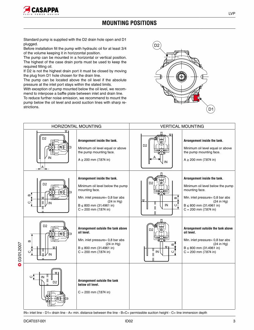
Standard pump is supplied with the D2 drain hole open and D1 plugged. Before installation fill the pump with hydraulic oil for at least 3/4 of the volume keeping it in horizzontal position. The pump can be mounted in a horizontal or vertical position. The highest of the case drain ports must be used to keep the required filling oil.If D2 is not the highest drain port it must be closed by moving the plug from D1 hole chosen for the drain line.The pump can be located above the oil level if the absolute pressure at the inlet port stays within the stated limits. With exception of pump mounted below the oil level, we recom-mend to interpose a baffle plate between inlet and drain line. To reduce further noise emission, we recommend to mount the pump below the oil level and avoid suction lines with sharp re-strictions.
IN= inlet line - D1= drain line - A= min. distance between the line - B+C= permissible suction height - C= line immersion depth
HORIZONTAL MOUNTING VERTICAL MOUNTING
Arrangement inside the tank.
Minimum oil level equal or above the pump mounting face.
A ≥ 200 mm (7.874 in)
Arrangement inside the tank.
Minimum oil level equal or above the pump mounting face.
A ≥ 200 mm (7.874 in)
Arrangement inside the tank.
Minimum oil level below the pump mounting face.
Min. inlet pressure= 0,8 bar abs (24 in Hg) B ≤ 800 mm (31.4961 in) C = 200 mm (7.874 in)
Arrangement inside the tank.
Minimum oil level below the pump mounting face.
Min. inlet pressure= 0,8 bar abs (24 in Hg) B ≤ 800 mm (31.4961 in) C = 200 mm (7.874 in)
Arrangement outside the tank above oil level.
Min. inlet pressure= 0,8 bar abs (24 in Hg) B ≤ 800 mm (31.4961 in) C = 200 mm (7.874 in)
Arrangement outside the tank above oil level.
Min. inlet pressure= 0,8 bar abs (24 in Hg) B ≤ 800 mm (31.4961 in) C = 200 mm (7.874 in)
Arrangement outside the tank below oil level.
C = 200 mm (7.874 in)
O 0
3/01
.200
7
4 ID02 DCAT037-001
LVP
(1) = with an inlet pressure of 1 bar abs (14.5 psi). Reducing the displacement or increasing the inlet pressure the max. speed change. See table at page 7. For different working conditions, please consult our technical sales department.
Pump type LVP 30 LVP 48 LVP 75 LVP 90Max. displacement(theor.) Vmax
cm3/rev (in3/rev)
28,7 (1.75)
45,4 (2.77)
73,6 (4.49)
87,9 (5.36)
Inlet pressure
bar abs. (in Hg) min. 0.8 (24)
bar abs. (psi) max. 25 (363)
Max. outletpressure pmax
bar (psi)
continuous 280 (4060) 280 (4060) 280 (4060) 250 (3625)
intermittent 315 (4568) 315 (4568) 315 (4568) 280 (4060)
peak 350 (5075) 350 (5075) 350 (5075) 315 (4568)
Max. drain linepressure
bar abs. (psi). 1,5 (22)
Min. speed (recommended) min-1 500
Max. speed nmaxmin-1 @ Vmax (1) 3000 2600 2600 2200
Max. delivery(theor.)
l/min (US gpm)
@ nmax 86,1 (22.75) 118,04 (31.19) 191,36 (50.56) 193,4 (51.10)
@ 1800 min-1 51,7 (13.66) 81,7 (21.59) 132,5 (35.01) 158,2 (41.80)
@ 1500 min-1 43,1 (11.39) 68,1 (17.99) 110,4 29.17) 131,9 (34.85)
Max. power (theor.)(∆p = pmax cont.)
kW (HP)
@ nmax 40,2 (53.9) 55,1 (73.8) 89,3 (119.7) 80,6 (108.0)
@ 1800 min-1 24,1 (32.3) 38,1 (51.1) 61,8 (82.8) 65,9 (88.3)
@ 1500 min-1 20,1 (26.9) 31,8 (42.6) 51,5 (69.0) 54,9 (73.6)
Max. torque (theor.) Nm (lbf in)
@ pmax cont. 127,9 (1132) 202,3 (1791) 328,0 (2903) 349,8 (3096)
@ 100 bar (1450 psi) 45,7 (404) 72,3 (640) 117,1 (1036) 139,9 (1238)
Moment of inertia kgm2
(ft2 lbs) 0,0020 (0.05) 0,0030 (0.07) 0,0080 (0.19) 0,0080 (0.19)
Fill volume l (US gallons) 0,7 (0.18) 0,9 (0.24) 1,5 (0.40) 1,5 (0.40)
Mass (without oil) kg (lbs) 18 (39.69) 24 (52.92) 33 (72.77) 33 (72.77)
Seals N= Buna V= Viton
Operating temperature °C (°F)
min. -25 (-13) -15 (5)
max. cont. 80 (176) 110 (230)
max. peak 100 (212) 125 (257)
TECHNICAL DATA
Technical data with mineral oil
HL or HLP mineral oil based hydraulic fluid to DIN 51524
O
OO O
O
O 0
4/04
.201
3R
epla
ces:
03/
01.2
007
DCAT037-001 ID02 5
LVP
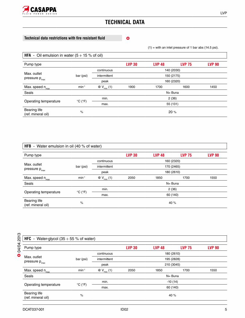
HFA - Oil emulsion in water (5 ÷ 15 % of oil)
TECHNICAL DATA
HFB - Water emulsion in oil (40 % of water)
HFC - Water-glycol (35 ÷ 55 % of water)
Technical data restrictions with !re resistant "uid
(1) = with an inlet pressure of 1 bar abs (14.5 psi).
Pump type LVP 30 LVP 48 LVP 75 LVP 90
Max. outletpressure pmax
bar (psi)
continuous 140 (2030)
intermittent 150 (2175)
peak 160 (2320)
Max. speed nmaxmin-1 @ Vmax (1) 1900 1700 1600 1450
Seals N= Buna
Operating temperature °C (°F)min. 2 (36)
max. 55 (131)
Bearing life(ref. mineral oil)
% 20 %
Pump type LVP 30 LVP 48 LVP 75 LVP 90
Max. outletpressure pmax
bar (psi)
continuous 160 (2320)
intermittent 170 (2465)
peak 180 (2610)
Max. speed nmaxmin-1 @ Vmax (1) 2050 1850 1700 1550
Seals N= Buna
Operating temperature °C (°F)min. 2 (36)
max. 60 (140)
Bearing life(ref. mineral oil)
% 40 %
Pump type LVP 30 LVP 48 LVP 75 LVP 90
Max. outletpressure pmax
bar (psi)
continuous 180 (2610)
intermittent 195 (2828)
peak 210 (3045)
Max. speed nmaxmin-1 @ Vmax (1) 2050 1850 1700 1550
Seals N= Buna
Operating temperature °C (°F)min. -10 (14)
max. 60 (140)
Bearing life(ref. mineral oil)
% 40 %
O
O 0
4/04
.201
3
6 ID02 DCAT037-001
LVP
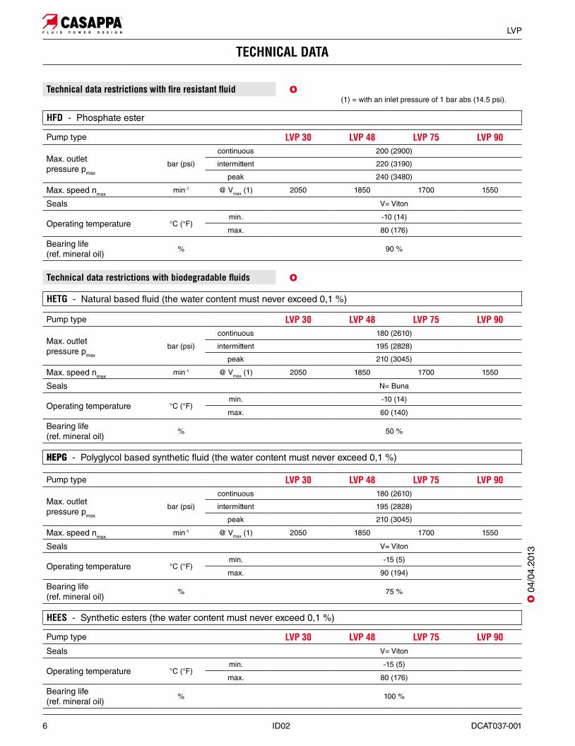
HFD - Phosphate ester
TECHNICAL DATA
HETG - Natural based fluid (the water content must never exceed 0,1 %)
HEPG - Polyglycol based synthetic fluid (the water content must never exceed 0,1 %)
Technical data restrictions with !re resistant "uid
Technical data restrictions with biodegradable !uids
HEES - Synthetic esters (the water content must never exceed 0,1 %)
(1) = with an inlet pressure of 1 bar abs (14.5 psi).
Pump type LVP 30 LVP 48 LVP 75 LVP 90
Max. outletpressure pmax
bar (psi)
continuous 200 (2900)
intermittent 220 (3190)
peak 240 (3480)
Max. speed nmaxmin-1 @ Vmax (1) 2050 1850 1700 1550
Seals V= Viton
Operating temperature °C (°F)min. -10 (14)
max. 80 (176)
Bearing life(ref. mineral oil)
% 90 %
Pump type LVP 30 LVP 48 LVP 75 LVP 90
Max. outletpressure pmax
bar (psi)
continuous 180 (2610)
intermittent 195 (2828)
peak 210 (3045)
Max. speed nmaxmin-1 @ Vmax (1) 2050 1850 1700 1550
Seals N= Buna
Operating temperature °C (°F)min. -10 (14)
max. 60 (140)
Bearing life(ref. mineral oil)
% 50 %
Pump type LVP 30 LVP 48 LVP 75 LVP 90
Max. outletpressure pmax
bar (psi)
continuous 180 (2610)
intermittent 195 (2828)
peak 210 (3045)
Max. speed nmaxmin-1 @ Vmax (1) 2050 1850 1700 1550
Seals V= Viton
Operating temperature °C (°F)min. -15 (5)
max. 90 (194)
Bearing life(ref. mineral oil)
% 75 %
Pump type LVP 30 LVP 48 LVP 75 LVP 90Seals V= Viton
Operating temperature °C (°F)min. -15 (5)
max. 80 (176)
Bearing life(ref. mineral oil)
% 100 %
O
O
O 0
4/04
.201
3
DCAT037-001 ID02 7
LVP
TECHNICAL DATA
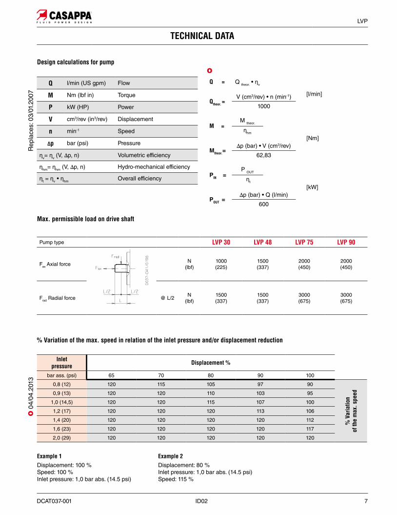
Design calculations for pump
Max. permissible load on drive shaft
Inlet pressure Displacement %
bar ass. (psi) 65 70 80 90 100
0,8 (12) 120 115 105 97 90
% V
aria
tion
of th
e m
ax. s
peed0,9 (13) 120 120 110 103 95
1,0 (14,5) 120 120 115 107 100
1,2 (17) 120 120 120 113 106
1,4 (20) 120 120 120 120 112
1,6 (23) 120 120 120 120 117
2,0 (29) 120 120 120 120 120
Example 1Displacement: 100 %Speed: 100 %Inlet pressure: 1,0 bar abs. (14.5 psi)
Example 2Displacement: 80 %Inlet pressure: 1,0 bar abs. (14.5 psi)Speed: 115 %
Q = Q theor. • Șv
[l/min]Qtheor. =
V (cm3/rev) • n (min-1)
1000
M =M theor.
[Nm]Șhm
Mtheor.=∆p (bar) • V (cm3/rev)
62,83
PIN =P OUT
[kW] Șt
POUT =∆p (bar) • Q (l/min)
600
% Variation of the max. speed in relation of the inlet pressure and/or displacement reduction
Pump type LVP 30 LVP 48 LVP 75 LVP 90
Fax Axial force N(lbf)
1000 (225)
1500 (337)
2000 (450)
2000 (450)
Frad Radial force @ L/2 N(lbf)
1500 (337)
1500 (337)
3000 (675)
3000 (675)
O
Rep
lace
s: 0
3/01
.200
7O
04/
04.2
013
Q l/min (US gpm) Flow
M Nm (lbf in) Torque
P kW (HP) Power
V cm3/rev (in3/rev) Displacement
n min-1 Speed
#p bar (psi) Pressure
Șv= Șv (V, ∆p, n) Volumetric efficiency
Șhm= Șhm (V, ∆p, n) Hydro-mechanical efficiency
Șt = Șv • Șhm Overall efficiency
8 ID02 DCAT037-001
LVP
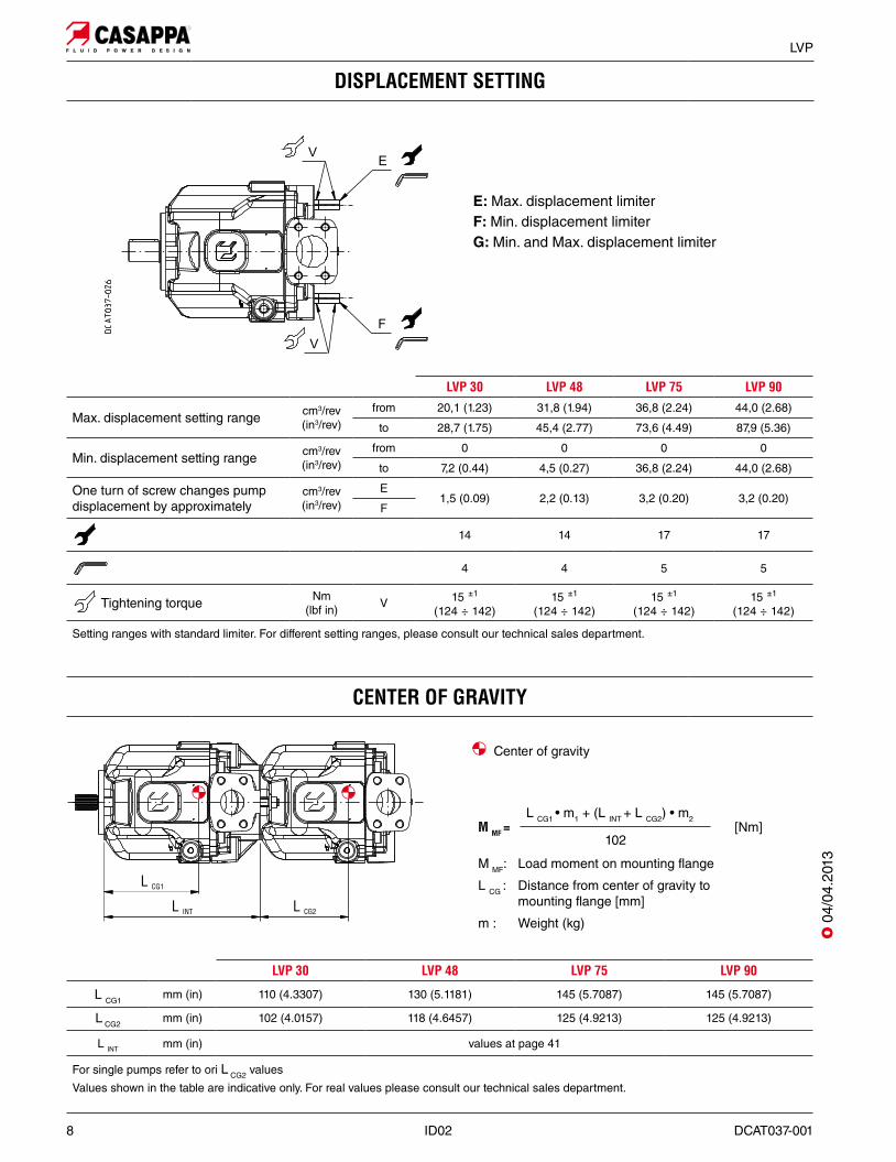
DISPLACEMENT SETTING
LVP 30 LVP 48 LVP 75 LVP 90
Max. displacement setting range cm3/rev(in3/rev)
from 20,1 (1.23) 31,8 (1.94) 36,8 (2.24) 44,0 (2.68)
to 28,7 (1.75) 45,4 (2.77) 73,6 (4.49) 87,9 (5.36)
Min. displacement setting range cm3/rev(in3/rev)
from 0 0 0 0
to 7,2 (0.44) 4,5 (0.27) 36,8 (2.24) 44,0 (2.68)
One turn of screw changes pump displacement by approximately
cm3/rev(in3/rev)
E1,5 (0.09) 2,2 (0.13) 3,2 (0.20) 3,2 (0.20)
F
14 14 17 17
4 4 5 5
Tightening torque Nm (lbf in) V 15 ±1
(124 ÷ 142)15 ±1
(124 ÷ 142)15 ±1
(124 ÷ 142)15 ±1
(124 ÷ 142)
Setting ranges with standard limiter. For different setting ranges, please consult our technical sales department.
CENTER OF GRAVITY
LVP 30 LVP 48 LVP 75 LVP 90
L CG1mm (in) 110 (4.3307) 130 (5.1181) 145 (5.7087) 145 (5.7087)
L CG2mm (in) 102 (4.0157) 118 (4.6457) 125 (4.9213) 125 (4.9213)
L INT mm (in) values at page 41
For single pumps refer to ori L CG2 values
Values shown in the table are indicative only. For real values please consult our technical sales department.
M MF =L CG1 • m1 + (L INT + L CG2) • m2
[Nm]102
M MF: Load moment on mounting flange
L CG : Distance from center of gravity to mounting flange [mm]
m : Weight (kg)
Center of gravity
E: Max. displacement limiterF: Min. displacement limiterG: Min. and Max. displacement limiter
O 0
4/04
.201
3
DCAT037-001 ID02 9
LVP
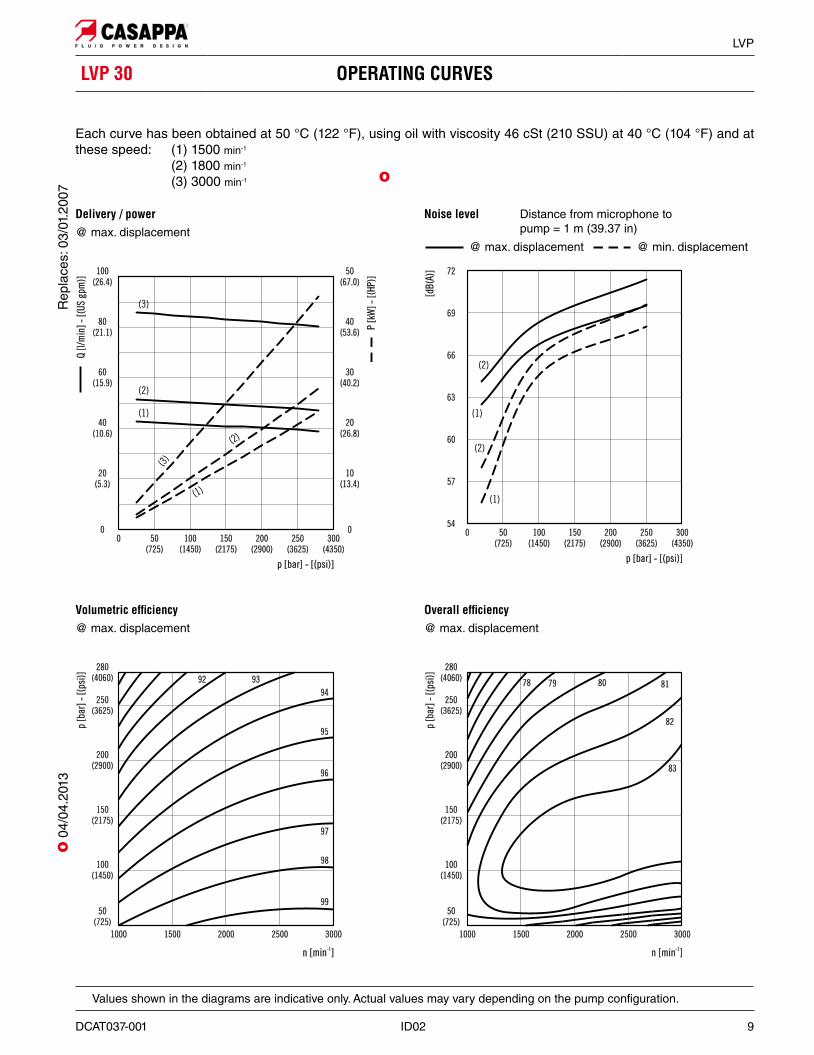
LVP 30 OPERATING CURVES
Delivery / power@ max. displacement
Volumetric ef!ciency@ max. displacement
Overall ef!ciency@ max. displacement
Each curve has been obtained at 50 °C (122 °F), using oil with viscosity 46 cSt (210 SSU) at 40 °C (104 °F) and at these speed: (1) 1500 min-1
(2) 1800 min-1
(3) 3000 min-1
Values shown in the diagrams are indicative only. Actual values may vary depending on the pump configuration.
O
Rep
lace
s: 0
3/01
.200
7O
04/
04.2
013
Noise level Distance from microphone to pump = 1 m (39.37 in)
@ max. displacement @ min. displacement
10 ID02 DCAT037-001
LVP
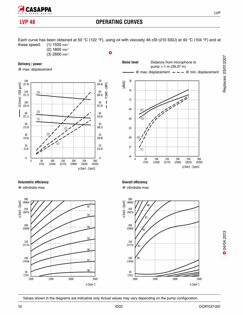
Each curve has been obtained at 50 °C (122 °F), using oil with viscosity 46 cSt (210 SSU) at 40 °C (104 °F) and at these speed: (1) 1500 min-1
(2) 1800 min-1
(3) 2600 min-1
LVP 48 OPERATING CURVES
Delivery / power@ max. displacement
Volumetric ef!ciency@ cilindrata max.
Overall ef!ciency@ cilindrata max.
Values shown in the diagrams are indicative only. Actual values may vary depending on the pump configuration.
O
Noise level Distance from microphone to pump = 1 m (39.37 in)
@ max. displacement @ min. displacement
O 0
4/04
.201
3R
epla
ces:
03/
01.2
007
DCAT037-001 ID02 11
LVP
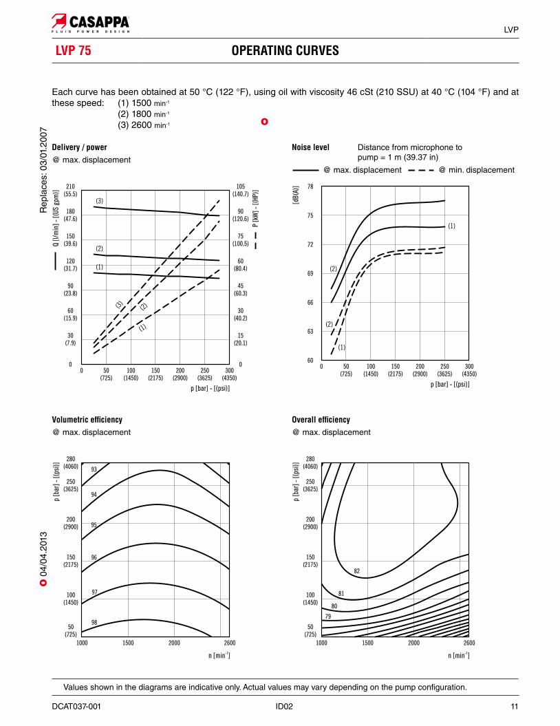
Each curve has been obtained at 50 °C (122 °F), using oil with viscosity 46 cSt (210 SSU) at 40 °C (104 °F) and at these speed: (1) 1500 min-1
(2) 1800 min-1
(3) 2600 min-1
LVP 75 OPERATING CURVES
Delivery / power@ max. displacement
Volumetric ef!ciency@ max. displacement
Overall ef!ciency@ max. displacement
Values shown in the diagrams are indicative only. Actual values may vary depending on the pump configuration.
O
Noise level Distance from microphone to pump = 1 m (39.37 in)
@ max. displacement @ min. displacement
Rep
lace
s: 0
3/01
.200
7O
04/
04.2
013

12 ID02 DCAT037-001
LVP
LVP 90 OPERATING CURVES
Each curve has been obtained at 50 °C (122 °F), using oil with viscosity 46 cSt (210 SSU) at 40 °C (104 °F) and at these speed: (1) 1500 min-1
(2) 1800 min-1
(3) 2200 min-1
Delivery / power@ max. displacement
Volumetric ef!ciency@ max. displacement
Overall ef!ciency@ max. displacement
Values shown in the diagrams are indicative only. Actual values may vary depending on the pump configuration.
O
Noise level Distance from microphone to pump = 1 m (39.37 in)
@ max. displacement @ min. displacement
O 0
4/04
.201
3R
epla
ces:
03/
01.2
007
DCAT037-001 ID02 13
LVP
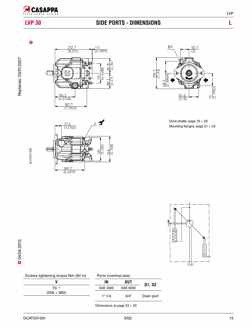
LVP 30 SIDE PORTS - DIMENSIONS L
Ports (nominal size)
IN OUTD1, D2
SAE 3000 SAE 6000
1” 1/4 3/4” Drain port
Dimensions at page 23 ÷ 25
Screws tightening torque Nm (lbf in)
V70 ±7
(558 ÷ 682)
Drive shafts: page 19 ÷ 20
Mounting flanges: page 21 ÷ 22
O
Rep
lace
s: 0
3/01
.200
7O
04/
04.2
013
14 ID02 DCAT037-001
LVP
LVP 30 REAR PORTS - DIMENSIONS P
Screws tightening torque Nm (lbf in)
V70 ±7
(558 ÷ 682)
Ports (nominal size)
IN OUTD1, D2
SAE 3000 SAE 6000
1” 1/4 3/4” Drain port
Dimensions at page 23 ÷ 25
Drive shafts: page 19 ÷ 20
Mounting flanges: page 21 ÷ 22
O
O 0
4/04
.201
3R
epla
ces:
03/
01.2
007
DCAT037-001 ID02 15
LVP
LVP 48 SIDE PORTS - DIMENSIONS L
Ports (nominal size)
IN OUTD1, D2
SAE 3000 SAE 6000
1” 1/2 1” Drain port
Dimensions at page 23 ÷ 25
Screws tightening torque Nm (lbf in)
V100 ±10
(797 ÷ 974)
Drive shafts: page 19 ÷ 20
Mounting flanges: page 21 ÷ 22
O
Rep
lace
s: 0
3/01
.200
7O
04/
04.2
013
16 ID02 DCAT037-001
LVP
LVP 48 REAR PORTS - DIMENSIONS P
Screws tightening torque Nm (lbf in)
V100 ±10
(797 ÷ 974)
Ports (nominal size)
IN OUTD1, D2
SAE 3000 SAE 6000
1” 1/2 1” Drain port
Dimensions at page 23 ÷ 25
Drive shafts: page 19 ÷ 20
Mounting flanges: page 21 ÷ 22
O
O 0
4/04
.201
3R
epla
ces:
03/
01.2
007
DCAT037-001 ID02 17
LVP
LVP 75-90 SIDE PORTS - DIMENSIONS L
Ports (nominal size)
IN OUTD1, D2
SAE 3000 SAE 6000
2” 1” 1/4 Drain port
Dimensions at page 23 ÷ 25
Screws tightening torque Nm (lbf in)
V130 ±13
(1036 ÷ 1266)
Drive shafts: page 19 ÷ 20
Mounting flanges: page 21 ÷ 22
O
Rep
lace
s: 0
3/01
.200
7O
04/
04.2
013
18 ID02 DCAT037-001
LVP
LVP 75-90 REAR PORTS - DIMENSIONS P
Screws tightening torque Nm (lbf in)
V130 ±13
(1036 ÷ 1266)
Ports (nominal size)
IN OUTD1, D2
SAE 3000 SAE 6000
2” 1” 1/4 Drain port
Dimensions at page 23 ÷ 25
Drive shafts: page 19 ÷ 20
Mounting flanges: page 21 ÷ 22
O
O 0
4/04
.201
3R
epla
ces:
03/
01.2
007
DCAT037-001 ID02 19
LVP
DRIVE SHAFTS
SAE “B” SPLINE 04Mounting face refers to flange code S5
SAE “C” SPLINE 06Mounting face refers to flange code S7
SAE “BB” SPLINE 05Mounting face refers to flange code S5
SAE “B” STRAIGHT 32Mounting face refers to flange code S5
SAE “BB” STRAIGHT 33Mounting face refers to flange code S5
SAE “C” STRAIGHT 34Mounting face refers to flange code S7
O
O
Ext. Involute Spline ANSI B92.1 with major diameter modified 14 teeth - 12/24 Pitch - 30 deg Flat root - Side fit - Class 5
O O
Ext. Involute Spline ANSI B92.1 with major diameter modified 15 teeth - 16/32 Pitch - 30 deg Flat root - Side fit - Class 5
O
O
Ext. Involute Spline ANSI B92.1 with major diameter modified 13 teeth - 16/32 Pitch - 30 deg Flat root - Side fit - Class 5R
epla
ces:
03/
01.2
007
O 0
4/04
.201
3
20 ID02 DCAT037-001
LVP
STRAIGHT Ø 22 68Mounting face refers to flange code Z1
DRIVE SHAFTS
STRAIGHT Ø 25 69Mounting face refers to flange code Z1
STRAIGHT Ø 32 70Mounting face refers to flange code Z2
O O
O
O 0
4/04
.201
3R
epla
ces:
03/
01.2
007
DCAT037-001 ID02 21
LVP
SAE “B”2 HOLES S5Conforms to SAE J744
SAE “C” 2 HOLES S7Conforms to SAE J744
DRIVE SHAFTSSee page 19
Pump type 06 34
LVP 75 x xLVP 90 x x
X Available combination
O
O
DRIVE SHAFTSSee page 19
Pump type
A 04 32 05 33mm (in)
LVP 30 178,7 (7.03) x xLVP 48 194,7 (7.66) x x x
X Available combination
O
MOUNTING FLANGES AND TABLE OF COMPATIBILITYR
epla
ces:
03/
01.2
007
O 0
4/04
.201
3
22 ID02 DCAT037-001
LVP
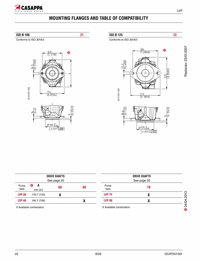
MOUNTING FLANGES AND TABLE OF COMPATIBILITY
ISO Ø 100 Z1Conforms to ISO 3019/2
ISO Ø 125 Z2Conforms to ISO 3019/2
O
O
DRIVE SHAFTSSee page 20
Pump type
A 68 69mm (in)
LVP 30 178,7 (7.03) xLVP 48 194,7 (7.66) x
X Available combination
O
DRIVE SHAFTSSee page 20
Pump type 70
LVP 75 xLVP 90 x
X Available combination
O 0
4/04
.201
3R
epla
ces:
03/
01.2
007
DCAT037-001 ID02 23
LVP
PORTS SIZES
INLET PORT - IN (SAE 3000 STANDARD PRESSURE)
CODE Nominalsize
A B C Dmm(in)
mm(in)
mm(in)
ThreadDepth mm (in)
Nm(lbf in)
Nm(lbf in)
MD 1” 1/4 32(1.2598)
58,7(2.3110)
30,2(1.1890)
M 1028 (1.1024)
20 +1
(177 ÷ 186) —
ME 1” 1/2 38,1(1.5000)
69,9(2.7520)
35,7(1.4055)
M 1226 (1.0236)
30 +2,5
(266 ÷ 288) —
MF 2” 51(2.0079)
77,8(3.0630)
42,9(1.6890)
M 1225 (0.9843)
30 +2,5
(266 ÷ 288) —
SAE FLANGED PORTS J518 SSMMetric thread ISO 60° conforms to ISO/R 262
Tightening torque for low pressure side port
Tightening torque for high pressure side port [values obtained at 350 bar (5075 psi)]
INLET / OUTLET PORTS DRAIN PORTS LOAD SENSINGPORTS
Ports typeSplitSSM
SplitSSS
GasBSPP
SAEODT (z)
GasBSPP
SAEODT (z)
IN OUT IN OUT D1 - D2 D1 - D2 X X
LVP 30 MD QB SD VB GD OB GA 03
LVP 48 ME QC SE VC GD OC GA 03
LVP 75 MF QD SF VD GE OC GA 03
LVP 90 MF QD SF VD GE OC GA 03
(z) Available only with inlet and outlet ports type Split SSS.
OUTLET PORT - OUT (SAE 6000 HIGH PRESSURE)
CODE Nominalsize
A B C Dmm(in)
mm(in)
mm(in)
ThreadDepth mm (in)
Nm(lbf in)
Nm(lbf in)
QB 3/4 19(0.7480)
50,8(2.0000)
23,8(0.9370)
M 1024 (0.9449) — 45+2,5
(398 ÷ 420)
QC 1” 38,1(1.5000)
69,9(2.7520)
35,7(1.4055)
M 1226 (1.0236) — 70+5
(620 ÷ 664)
QD 1” 1/4 51(2.0079)
77,8(3.0630)
42,9(1.6890)
M 1225 (0.9843) — 60+5
(531 ÷ 575)
O
O O
O O
O
O 0
3/01
.200
7
24 ID02 DCAT037-001
LVP
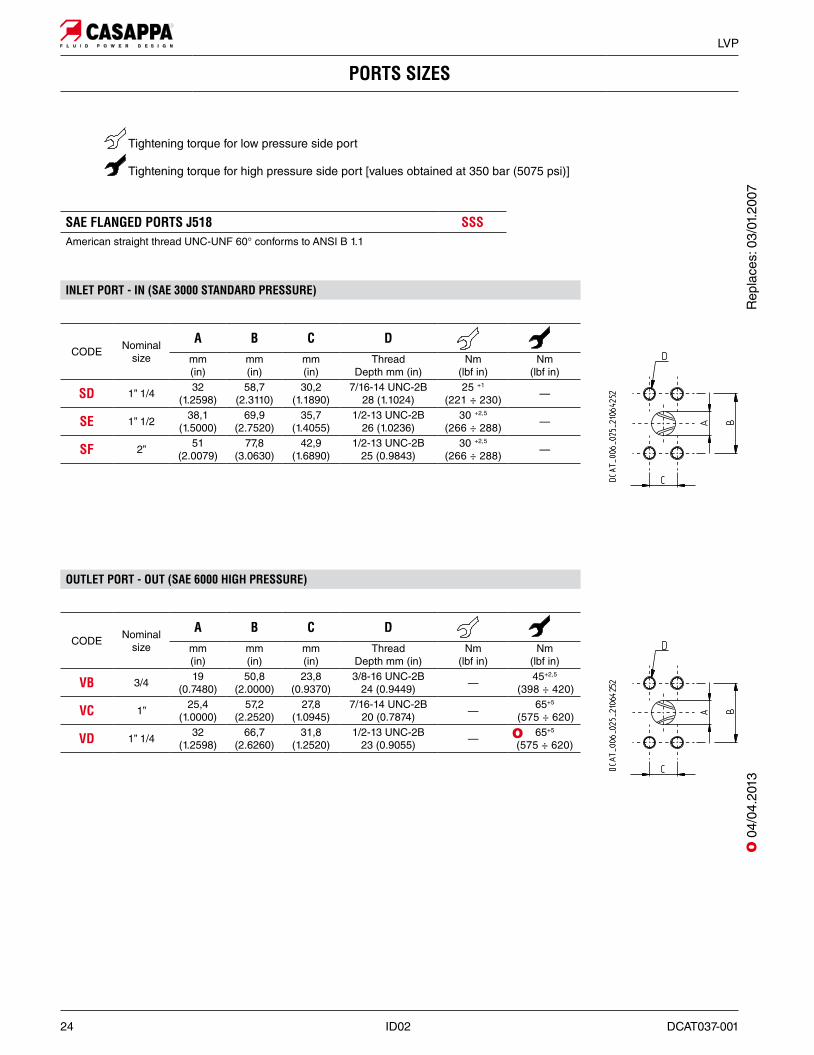
PORTS SIZES
Tightening torque for low pressure side port
Tightening torque for high pressure side port [values obtained at 350 bar (5075 psi)]
SAE FLANGED PORTS J518 SSSAmerican straight thread UNC-UNF 60° conforms to ANSI B 1.1
INLET PORT - IN (SAE 3000 STANDARD PRESSURE)
CODE Nominalsize
A B C Dmm(in)
mm(in)
mm(in)
ThreadDepth mm (in)
Nm(lbf in)
Nm(lbf in)
SD 1” 1/4 32(1.2598)
58,7(2.3110)
30,2(1.1890)
7/16-14 UNC-2B 28 (1.1024)
25 +1
(221 ÷ 230) —
SE 1” 1/2 38,1(1.5000)
69,9(2.7520)
35,7(1.4055)
1/2-13 UNC-2B26 (1.0236)
30 +2,5
(266 ÷ 288) —
SF 2” 51(2.0079)
77,8(3.0630)
42,9(1.6890)
1/2-13 UNC-2B25 (0.9843)
30 +2,5
(266 ÷ 288) —
OUTLET PORT - OUT (SAE 6000 HIGH PRESSURE)
CODE Nominalsize
A B C Dmm(in)
mm(in)
mm(in)
ThreadDepth mm (in)
Nm(lbf in)
Nm(lbf in)
VB 3/4 19(0.7480)
50,8(2.0000)
23,8(0.9370)
3/8-16 UNC-2B24 (0.9449) — 45+2,5
(398 ÷ 420)
VC 1” 25,4(1.0000)
57,2(2.2520)
27,8(1.0945)
7/16-14 UNC-2B20 (0.7874) — 65+5
(575 ÷ 620)
VD 1” 1/4 32(1.2598)
66,7(2.6260)
31,8(1.2520)
1/2-13 UNC-2B23 (0.9055) — 65+5
(575 ÷ 620)O
O 0
4/04
.201
3R
epla
ces:
03/
01.2
007
DCAT037-001 ID02 25
LVP
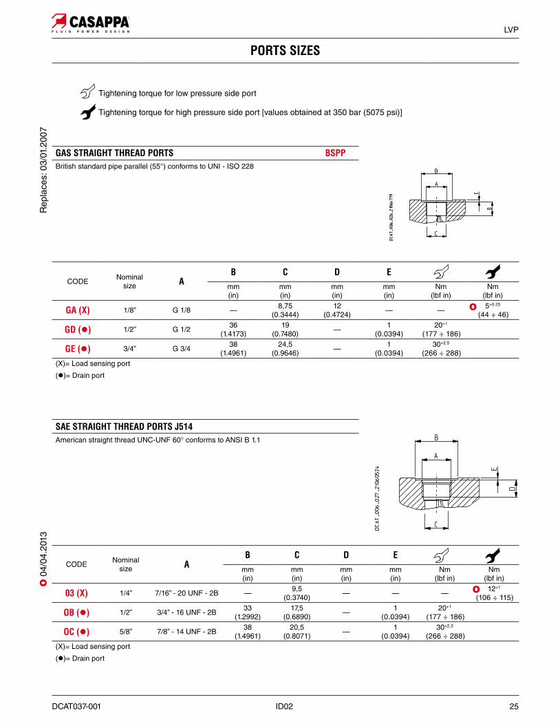
PORTS SIZES
SAE STRAIGHT THREAD PORTS J514American straight thread UNC-UNF 60° conforms to ANSI B 1.1
GAS STRAIGHT THREAD PORTS BSPPBritish standard pipe parallel (55°) conforms to UNI - ISO 228
Tightening torque for low pressure side port
Tightening torque for high pressure side port [values obtained at 350 bar (5075 psi)]
CODE Nominalsize A
B C D Emm(in)
mm(in)
mm (in)
mm (in)
Nm(lbf in)
Nm(lbf in)
GA (X) 1/8” G 1/8 — 8,75(0.3444)
12(0.4724) — — 5+0.25
(44 ÷ 46)
GD (z) 1/2” G 1/2 36(1.4173)
19(0.7480) — 1
(0.0394)20+1
(177 ÷ 186)
GE (z) 3/4” G 3/4 38(1.4961)
24,5(0.9646) — 1
(0.0394)30+2,5
(266 ÷ 288)(X)= Load sensing port
(z)= Drain port
O
CODE Nominalsize A
B C D Emm(in)
mm(in)
mm (in)
mm (in)
Nm(lbf in)
Nm(lbf in)
03 (X) 1/4” 7/16” - 20 UNF - 2B — 9,5(0.3740) — — — 12+1
(106 ÷ 115)
OB (z) 1/2” 3/4” - 16 UNF - 2B 33(1.2992)
17,5(0.6890) — 1
(0.0394)20+1
(177 ÷ 186)
OC (z) 5/8” 7/8” - 14 UNF - 2B 38(1.4961)
20,5(0.8071) — 1
(0.0394)30+2,5
(266 ÷ 288)(X)= Load sensing port
(z)= Drain port
O
Rep
lace
s: 0
3/01
.200
7O
04/
04.2
013
26 ID02 DCAT037-001
LVP
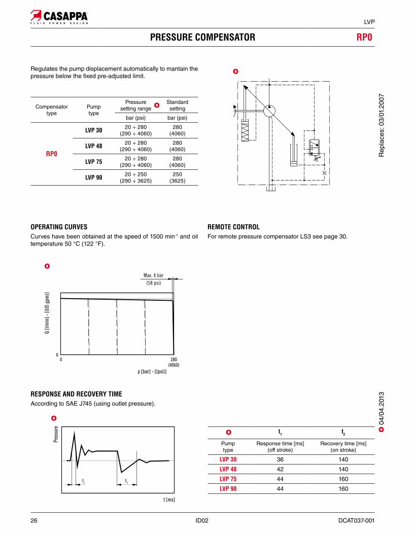
PRESSURE COMPENSATOR RP0
Regulates the pump displacement automatically to mantain the pressure below the fixed pre-adjusted limit.
OPERATING CURVESCurves have been obtained at the speed of 1500 min-1 and oil temperature 50 °C (122 °F).
REMOTE CONTROLFor remote pressure compensator LS3 see page 30.
RESPONSE AND RECOVERY TIMEAccording to SAE J745 (using outlet pressure).
Compensator type
Pumptype
Pressure setting range
Standardsetting
bar (psi) bar (psi)
RP0
LVP 30 20 ÷ 280(290 ÷ 4060)
280(4060)
LVP 48 20 ÷ 280(290 ÷ 4060)
280(4060)
LVP 75 20 ÷ 280(290 ÷ 4060)
280(4060)
LVP 90 20 ÷ 250(290 ÷ 3625)
250(3625)
t1 t2
Pumptype
Response time [ms](off stroke)
Recovery time [ms](on stroke)
LVP 30 36 140
LVP 48 42 140
LVP 75 44 160
LVP 90 44 160
O
O
O
O
O
O 0
4/04
.201
3R
epla
ces:
03/
01.2
007
DCAT037-001 ID02 27
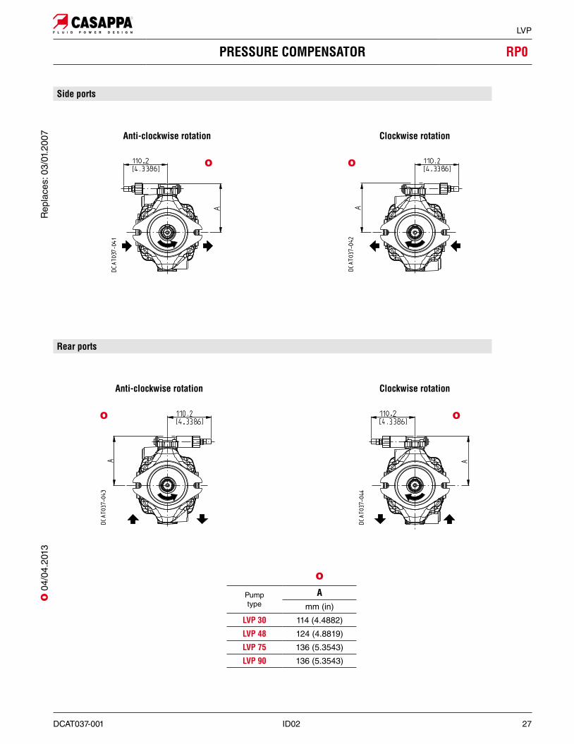
LVP
PRESSURE COMPENSATOR RP0
Anti-clockwise rotation Clockwise rotation
Anti-clockwise rotation Clockwise rotation
Pumptype
Amm (in)
LVP 30 114 (4.4882)
LVP 48 124 (4.8819)
LVP 75 136 (5.3543)
LVP 90 136 (5.3543)
O
Side ports
Rear ports
O O
OO
Rep
lace
s: 0
3/01
.200
7O
04/
04.2
013
28 ID02 DCAT037-001
LVP
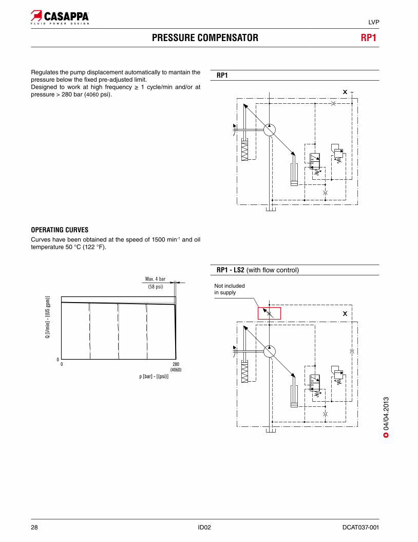
PRESSURE COMPENSATOR RP1
Regulates the pump displacement automatically to mantain the pressure below the fixed pre-adjusted limit. Designed to work at high frequency ≥ 1 cycle/min and/or at pressure > 280 bar (4060 psi).
RP1
OPERATING CURVESCurves have been obtained at the speed of 1500 min-1 and oil temperature 50 °C (122 °F).
RP1 - LS2 (with flow control)
Not included in supply
O 0
4/04
.201
3
DCAT037-001 ID02 29
LVP
PRESSURE COMPENSATOR RP1
Pumptype
Amm (in)
LVP 30 151 (5.9449)
LVP 48 161 (6.3386)
LVP 75 173 (6.8110)
LVP 90 173 (6.8110)
Anti-clockwise rotation Clockwise rotation
Anti-clockwise rotation Clockwise rotation
Side ports
Rear ports
O 0
4/04
.201
3
30 ID02 DCAT037-001
LVP
FLOW COMPENSATOR (Load-sensing) LS
Regulates the pump displacement to maintain a constant (load independent) pressure drop across a flow metering device. In the standard version the flow compensator is combined with pressure compensator.
OPERATING CURVESCurves have been obtained at the speed of 1500 min-1 and oil temperature 50 °C (122 °F).
RESPONSE TIMEAccording to SAE J745 (using outlet pressure).
Curve at variable speed
Pilot flow ≈ 1,3 ÷ 1,5 l/min (0.34 ÷ 0.40 US gpm).
In standard setting conditions 14 bar (203 psi) the stand-by pressure is 15±2 bar (218±29 psi).
LS0 - LS2
O
LS3 - remote pressure compensator
Flowcompensator
type
Pressurecompensator
Differentialpressure
setting range
Standardsetting
bar (psi) bar (psi)
LS0 (�) RPO10 ÷ 40
(145 ÷ 580)14
(203)LS2 (�) RPO
LS3 (z) RPO
(�): Suggested when the directional control valve does not have the bleed function.
(�): Y is plugged. Suggested when the directional control valve has the bleed function.
(z): For remote pressure control.
#Q max t1 (z)
Pump type l/min (US gpm) Response time [ms](off stroke)
LVP 30 0,9 (0.24) 115
LVP 48 1,7 (0.45) 117
LVP 75 2,5 (0.66) 120
LVP 90 2,5 (0.66) 120
(z) According to SAE J745 (using outlet pressure).
Not included in supply
Z Option (see page 32 for more information)
Not included in supply
Z Option (see page 32 for more information)
O
O
O
O 0
4/04
.201
3R
epla
ces:
03/
01.2
007
DCAT037-001 ID02 31
LVP
FLOW COMPENSATOR (Load-sensing) LS
Pumptype
A Bmm (in) mm (in)
LVP 30 145 (5.7087) 101 (3.9764)
LVP 48 154 (6.0630) 110 (4.3307)
LVP 75 167 (6.5748) 123 (4.8425)
LVP 90 167 (6.5748) 123 (4.8425)
X: Load-sensing port. Dimensions at page 25
Anti-clockwise rotation Clockwise rotation
Anti-clockwise rotation Clockwise rotation
O
Side ports
Rear ports
O O
O O
Rep
lace
s: 0
3/01
.200
7O
04/
04.2
013
32 ID02 DCAT037-001
LVP
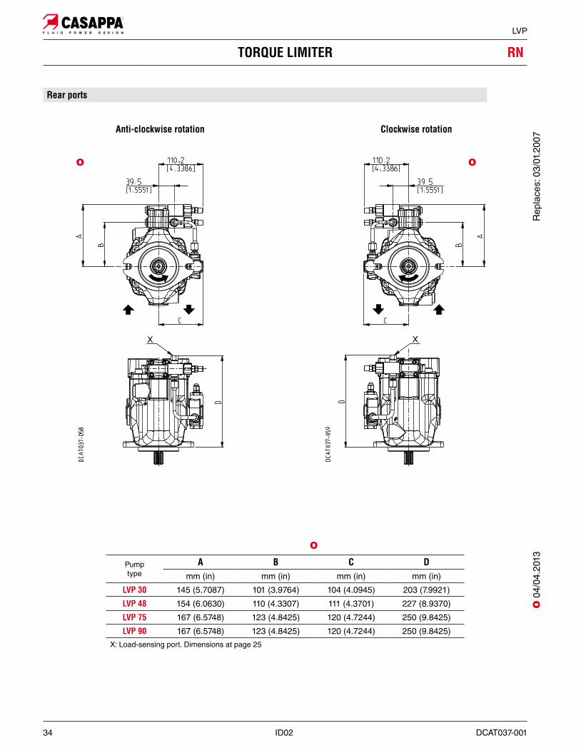
TORQUE LIMITER RN
Regulates the pump displacement according to the system pressure, to maintain the pre-adjusted torque value and protect the prime mover from overload. To have the best torque limiter regulation, the pre-adjusted absorbed torque has to be higher than the value shown in the following table.
Pumptype
Min. torque Min. power (z)
Nm (lbf in) kW (HP)
LVP 30 43 (381) 6,7 (9.0)
LVP 48 68 (602) 10,7 (14.3)
LVP 75 113 (1000) 17,8 (23.9)
LVP 90 132 (1168) 20,7 (27.7)
(z) @ 1500 min-1
For lower torque setting values, the regulator limits the maxi-mum working pressure to a value lower than the standard set-ting for the pressure regulator 280 bar (4060 psi).
When ordering the torque limiter please specify the requested value of torque [eg. 70 Nm (620 lbf in)] or the requested power and speed [eg. 10 kW (13.4 HP) at 1500 min-1].
OPERATING CURVES
O
Z Option
Damping restrictor for critical applications.In case of system instability or pressure oscillations, the addi-tional damping restrictor slows down the pump control system, damping the regulation transients. The pump regulation response time increases. The use of the damping restrictor must be evaluated and ap-proved by Casappa technical sales department for the specific application.
Not included in supply
Z Option
Z OptionTheoretical power
RN0 - StandardTorque limitation for closed center valve.
RN1 - Internal pilotTorque limitation for open center valve.
O
O 0
4/04
.201
3R
epla
ces:
03/
01.2
007
DCAT037-001 ID02 33
LVP
TORQUE LIMITER RN
Pumptype
A B C Dmm (in) mm (in) mm (in) mm (in)
LVP 30 145 (5.7087) 101 (3.9764) 104 (4.0945) 203 (7.9921)
LVP 48 154 (6.0630) 110 (4.3307) 111 (4.3701) 227 (8.9370)
LVP 75 167 (6.5748) 123 (4.8425) 120 (4.7244) 250 (9.8425)
LVP 90 167 (6.5748) 123 (4.8425) 120 (4.7244) 250 (9.8425)
X: Load-sensing port. Dimensions at page 25
Anti-clockwise rotation Clockwise rotation
Side ports
O O
O
Rep
lace
s: 0
3/01
.200
7O
04/
04.2
013
34 ID02 DCAT037-001
LVP
TORQUE LIMITER RN
Anti-clockwise rotation Clockwise rotation
Pumptype
A B C Dmm (in) mm (in) mm (in) mm (in)
LVP 30 145 (5.7087) 101 (3.9764) 104 (4.0945) 203 (7.9921)
LVP 48 154 (6.0630) 110 (4.3307) 111 (4.3701) 227 (8.9370)
LVP 75 167 (6.5748) 123 (4.8425) 120 (4.7244) 250 (9.8425)
LVP 90 167 (6.5748) 123 (4.8425) 120 (4.7244) 250 (9.8425)
X: Load-sensing port. Dimensions at page 25
Rear ports
O O
OO
04/
04.2
013
Rep
lace
s: 0
3/01
.200
7
DCAT037-001 ID02 35
LVP
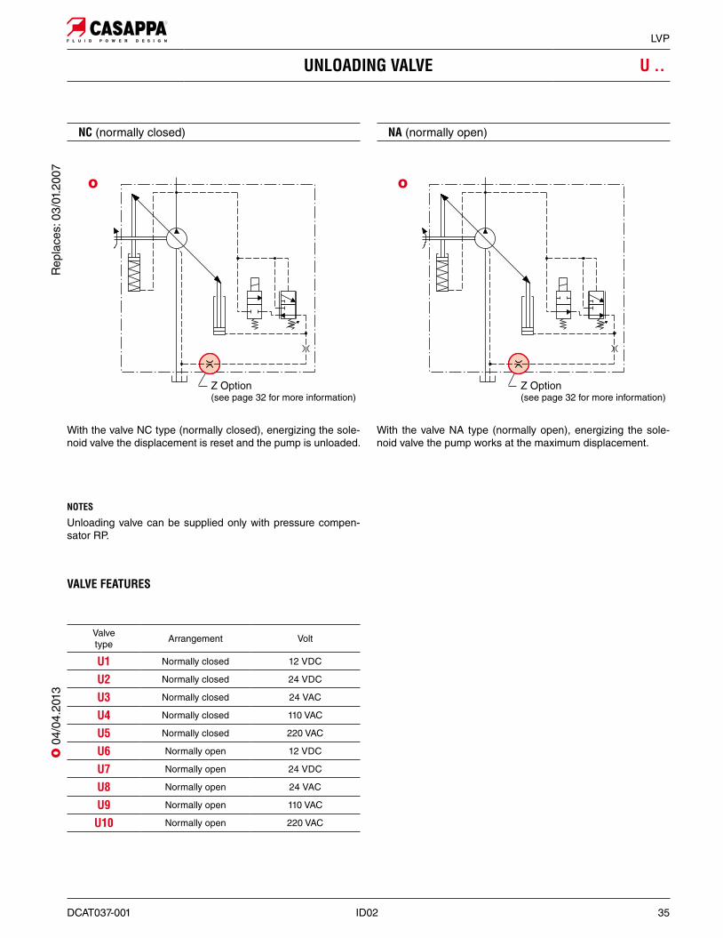
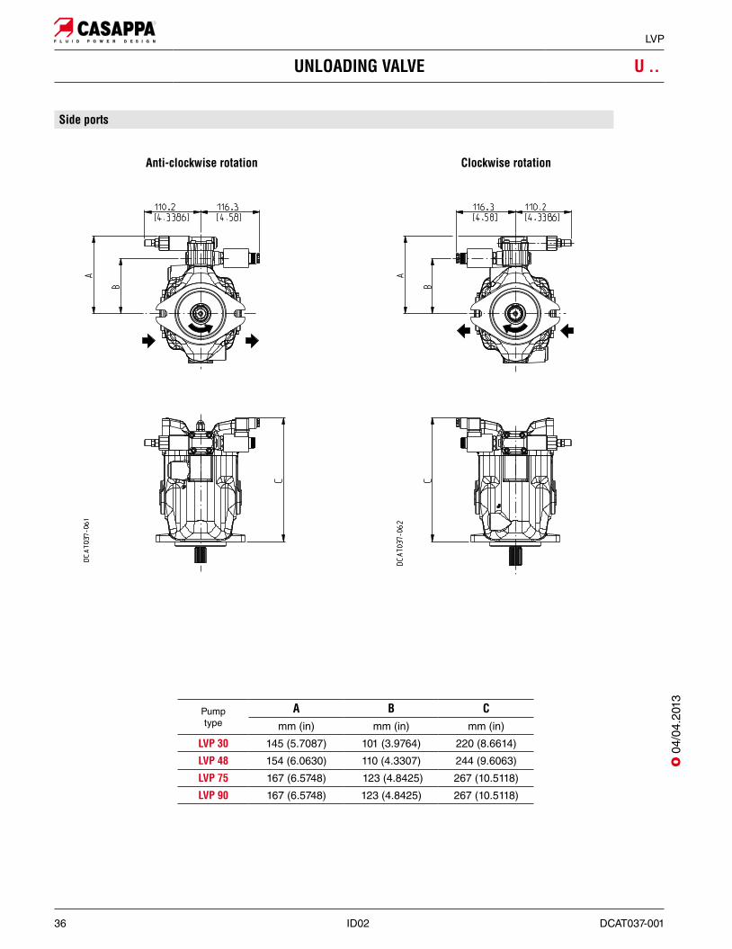
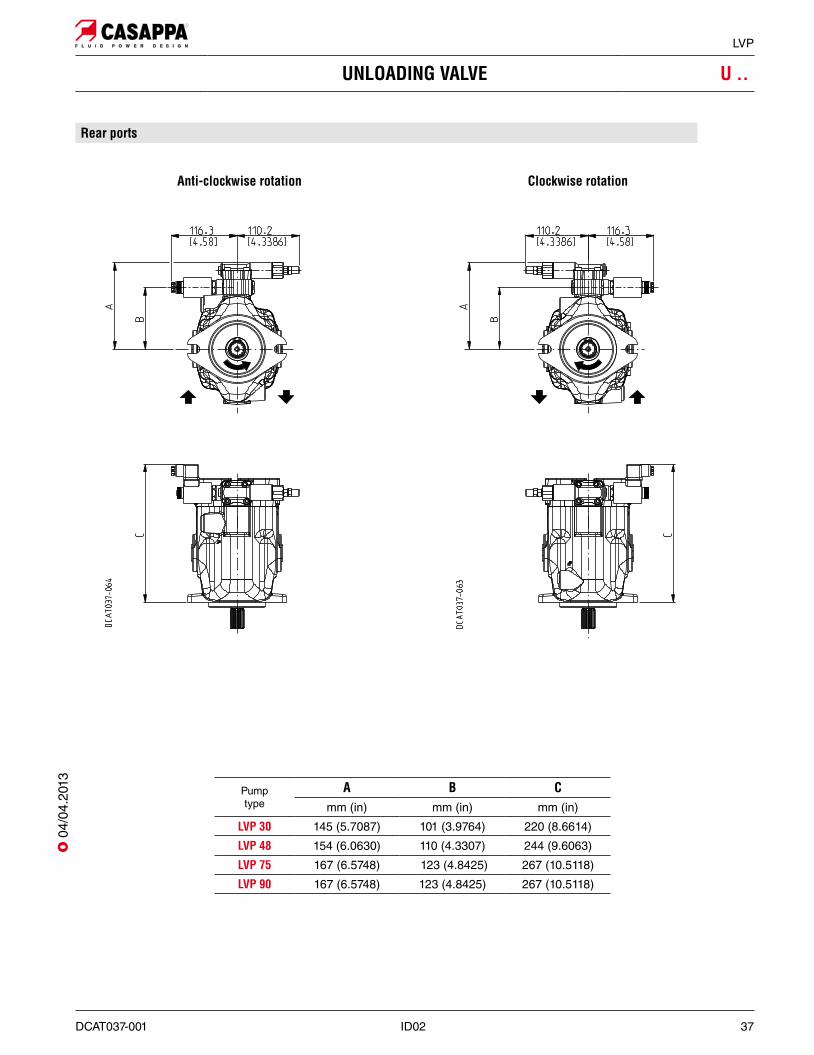
UNLOADING VALVE U ..
O
With the valve NC type (normally closed), energizing the sole-noid valve the displacement is reset and the pump is unloaded.
NC (normally closed) NA (normally open)
With the valve NA type (normally open), energizing the sole-noid valve the pump works at the maximum displacement.
NOTES
Unloading valve can be supplied only with pressure compen-sator RP.
VALVE FEATURES
Valvetype Arrangement Volt
U1 Normally closed 12 VDC
U2 Normally closed 24 VDC
U3 Normally closed 24 VAC
U4 Normally closed 110 VAC
U5 Normally closed 220 VAC
U6 Normally open 12 VDC
U7 Normally open 24 VDC
U8 Normally open 24 VAC
U9 Normally open 110 VAC
U10 Normally open 220 VAC
Z Option (see page 32 for more information)
Z Option (see page 32 for more information)
O
Rep
lace
s: 0
3/01
.200
7O
04/
04.2
013
36 ID02 DCAT037-001
LVP
UNLOADING VALVE U ..
Pumptype
A B C mm (in) mm (in) mm (in)
LVP 30 145 (5.7087) 101 (3.9764) 220 (8.6614)
LVP 48 154 (6.0630) 110 (4.3307) 244 (9.6063)
LVP 75 167 (6.5748) 123 (4.8425) 267 (10.5118)
LVP 90 167 (6.5748) 123 (4.8425) 267 (10.5118)
Anti-clockwise rotation Clockwise rotation
Side ports
O 0
4/04
.201
3
DCAT037-001 ID02 37
LVP
UNLOADING VALVE U ..
Anti-clockwise rotation Clockwise rotation
Rear ports
Pumptype
A B C mm (in) mm (in) mm (in)
LVP 30 145 (5.7087) 101 (3.9764) 220 (8.6614)
LVP 48 154 (6.0630) 110 (4.3307) 244 (9.6063)
LVP 75 167 (6.5748) 123 (4.8425) 267 (10.5118)
LVP 90 167 (6.5748) 123 (4.8425) 267 (10.5118)
O 0
4/04
.201
3
38 ID02 DCAT037-001
LVP
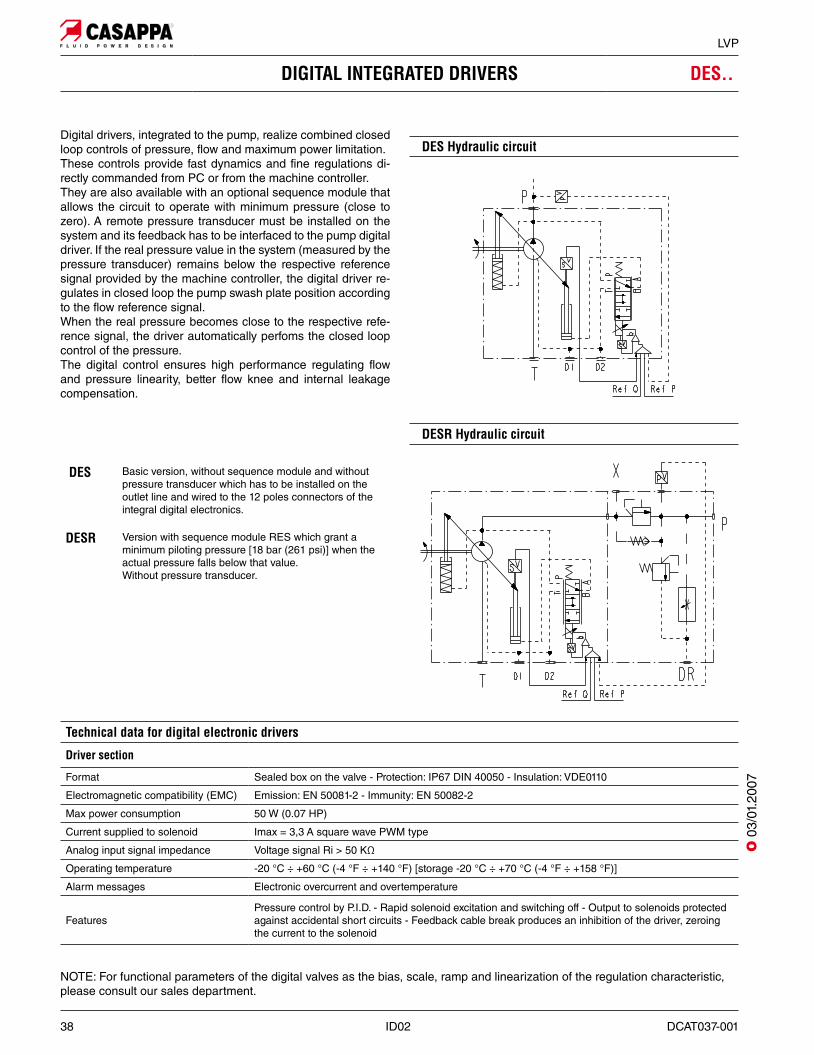
DIGITAL INTEGRATED DRIVERS DES..
Digital drivers, integrated to the pump, realize combined closed loop controls of pressure, flow and maximum power limitation.These controls provide fast dynamics and fine regulations di-rectly commanded from PC or from the machine controller.They are also available with an optional sequence module that allows the circuit to operate with minimum pressure (close to zero). A remote pressure transducer must be installed on the system and its feedback has to be interfaced to the pump digital driver. If the real pressure value in the system (measured by the pressure transducer) remains below the respective reference signal provided by the machine controller, the digital driver re-gulates in closed loop the pump swash plate position according to the flow reference signal. When the real pressure becomes close to the respective refe-rence signal, the driver automatically perfoms the closed loop control of the pressure.The digital control ensures high performance regulating flow and pressure linearity, better flow knee and internal leakage compensation.
DES Basic version, without sequence module and without pressure transducer which has to be installed on the outlet line and wired to the 12 poles connectors of the integral digital electronics.
DESR Version with sequence module RES which grant a minimum piloting pressure [18 bar (261 psi)] when the actual pressure falls below that value. Without pressure transducer.
Technical data for digital electronic drivers
Driver section
Format Sealed box on the valve - Protection: IP67 DIN 40050 - Insulation: VDE0110
Electromagnetic compatibility (EMC) Emission: EN 50081-2 - Immunity: EN 50082-2
Max power consumption 50 W (0.07 HP)
Current supplied to solenoid Imax = 3,3 A square wave PWM type
Analog input signal impedance Voltage signal Ri > 50 KΩ
Operating temperature -20 °C ÷ +60 °C (-4 °F ÷ +140 °F) [storage -20 °C ÷ +70 °C (-4 °F ÷ +158 °F)]
Alarm messages Electronic overcurrent and overtemperature
FeaturesPressure control by P.I.D. - Rapid solenoid excitation and switching off - Output to solenoids protected against accidental short circuits - Feedback cable break produces an inhibition of the driver, zeroing the current to the solenoid
NOTE: For functional parameters of the digital valves as the bias, scale, ramp and linearization of the regulation characteristic, please consult our sales department.
DES Hydraulic circuit
DESR Hydraulic circuit
O 0
3/01
.200
7
DCAT037-001 ID02 39
LVP
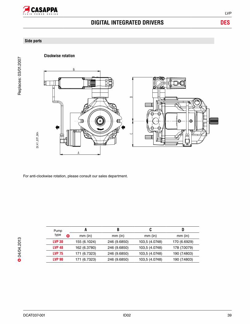
DIGITAL INTEGRATED DRIVERS DES
Clockwise rotation
For anti-clockwise rotation, please consult our sales department.
Side ports
Pumptype
A B C Dmm (in) mm (in) mm (in) mm (in)
LVP 30 155 (6.1024) 246 (9.6850) 103,5 (4.0748) 170 (6.6929)
LVP 48 162 (6.3780) 246 (9.6850) 103,5 (4.0748) 178 (7.0079)
LVP 75 171 (6.7323) 246 (9.6850) 103,5 (4.0748) 190 (7.4803)
LVP 90 171 (6.7323) 246 (9.6850) 103,5 (4.0748) 190 (7.4803)
O
Rep
lace
s: 0
3/01
.200
7O
04/
04.2
013
40 ID02 DCAT037-001
LVP
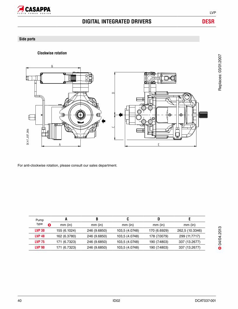
DIGITAL INTEGRATED DRIVERS DESR
For anti-clockwise rotation, please consult our sales department.
Clockwise rotation
Side ports
Pumptype
A B C D Emm (in) mm (in) mm (in) mm (in) mm (in)
LVP 30 155 (6.1024) 246 (9.6850) 103,5 (4.0748) 170 (6.6929) 262,5 (10.3346)
LVP 48 162 (6.3780) 246 (9.6850) 103,5 (4.0748) 178 (7.0079) 299 (11.7717)
LVP 75 171 (6.7323) 246 (9.6850) 103,5 (4.0748) 190 (7.4803) 337 (13.2677)
LVP 90 171 (6.7323) 246 (9.6850) 103,5 (4.0748) 190 (7.4803) 337 (13.2677)
OO
04/
04.2
013
Rep
lace
s: 0
3/01
.200
7
DCAT037-001 ID02 41
LVP
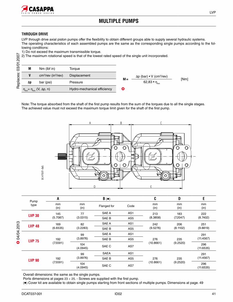
MULTIPLE PUMPS
THROUGH DRIVELVP through drive axial piston pumps offer the flexibility to obtain different groups able to supply several hydraulic systems. The operating characteristics of each assembled pumps are the same as the corresponding single pumps according to the fol-lowing conditions:1) Do not exceed the maximum transmissible torque.2) The maximum rotational speed is that of the lowest rated speed of the single unit incorporated.
M Nm (lbf in) Torque
V cm3/rev (in3/rev) Displacement
#p bar (psi) Pressure
Șhm= Șhm (V, ∆p, n) Hydro-mechanical efficiency
Note: The torque absorbed from the shaft of the first pump results from the sum of the torques due to all the single stages. The achieved value must not exceed the maximum torque limit given for the shaft of the first pump.
M =∆p (bar) • V (cm3/rev)
[Nm]62,83 • Șhm
O
Pumptype
A B (z) C D Emm (in)
mm (in) Flanged for Code mm
(in)mm (in)
mm (in)
LVP 30 145(5.7087)
77(3.0315)
SAE A AS1 213(8.3858)
183(7.2047)
222(8.7402)SAE B AS5
LVP 48 169(6.6535)
82(3.2283)
SAE A AS1 242(9.5276)
206(8.1102)
251(9.8819)SAE B AS5
LVP 75 192(7.5591)
99(3.8976)
SAE A AS1
276(10.8661)
235(9.2520)
291(11.4567)SAE B AS5
104(4.0945) SAE C AS7 296
(11.6535)
LVP 90 192(7.5591)
99(3.8976)
SAEA AS1
276(10.8661)
235(9.2520)
291(11.4567)SAE B AS5
104(4.0945) SAE C AS7 296
(11.6535)
Overall dimensions: the same as the single pumps.Ports dimensions at pages 23 ÷ 25. - Screws are supplied with the first pump.(z) Cover kit are available to obtain single pumps starting from front sections of multiple pumps. Dimensions at page. 49
Rep
lace
s: 0
3/01
.200
7O
04/
04.2
013
42 ID02 DCAT037-001
LVP
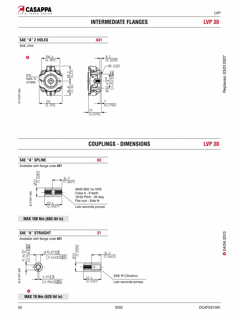
INTERMEDIATE FLANGES LVP 30
SAE “A” SPLINE 03Available with flange code AS1
SAE “A” STRAIGHT 31Available with flange code AS1
MAX 100 Nm (885 lbf in)
SAE “A” 2 HOLES AS1SAE J744
COUPLINGS - DIMENSIONS LVP 30
MAX 70 Nm (620 lbf in)O
ANSI B92.1a-1976 Class 6 - 9 teeth 16/32 Pitch - 30 deg Flat root - Side fit
Lato seconda pompa
SAE “A” Cilindrico
Lato seconda pompa
O
O 0
4/04
.201
3R
epla
ces:
03/
01.2
007
DCAT037-001 ID02 43
LVP
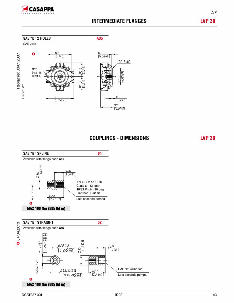
INTERMEDIATE FLANGES LVP 30
SAE “B” SPLINE 04Available with flange code AS5
SAE “B” STRAIGHT 32Available with flange code AS5
COUPLINGS - DIMENSIONS LVP 30
SAE “B” 2 HOLES AS5SAE J744
MAX 100 Nm (885 lbf in)O
MAX 100 Nm (885 lbf in)O
ANSI B92.1a-1976 Class 6 - 13 teeth 16/32 Pitch - 30 deg Flat root - Side fit
Lato seconda pompa
SAE “B” Cilindrico
Lato seconda pompa
O
Rep
lace
s: 0
3/01
.200
7O
04/
04.2
013
44 ID02 DCAT037-001
LVP
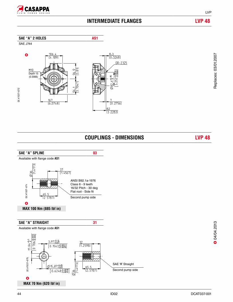
INTERMEDIATE FLANGES LVP 48
SAE “A” SPLINE 03Available with flange code AS1
SAE “A” STRAIGHT 31Available with flange code AS1
SAE “A” 2 HOLES AS1SAE J744
COUPLINGS - DIMENSIONS LVP 48
MAX 100 Nm (885 lbf in)O
MAX 70 Nm (620 lbf in)O
ANSI B92.1a-1976 Class 6 - 9 teeth 16/32 Pitch - 30 deg Flat root - Side fit
Second pump side
SAE “A” Straight
Second pump side
O
O 0
4/04
.201
3R
epla
ces:
03/
01.2
007
DCAT037-001 ID02 45
LVP
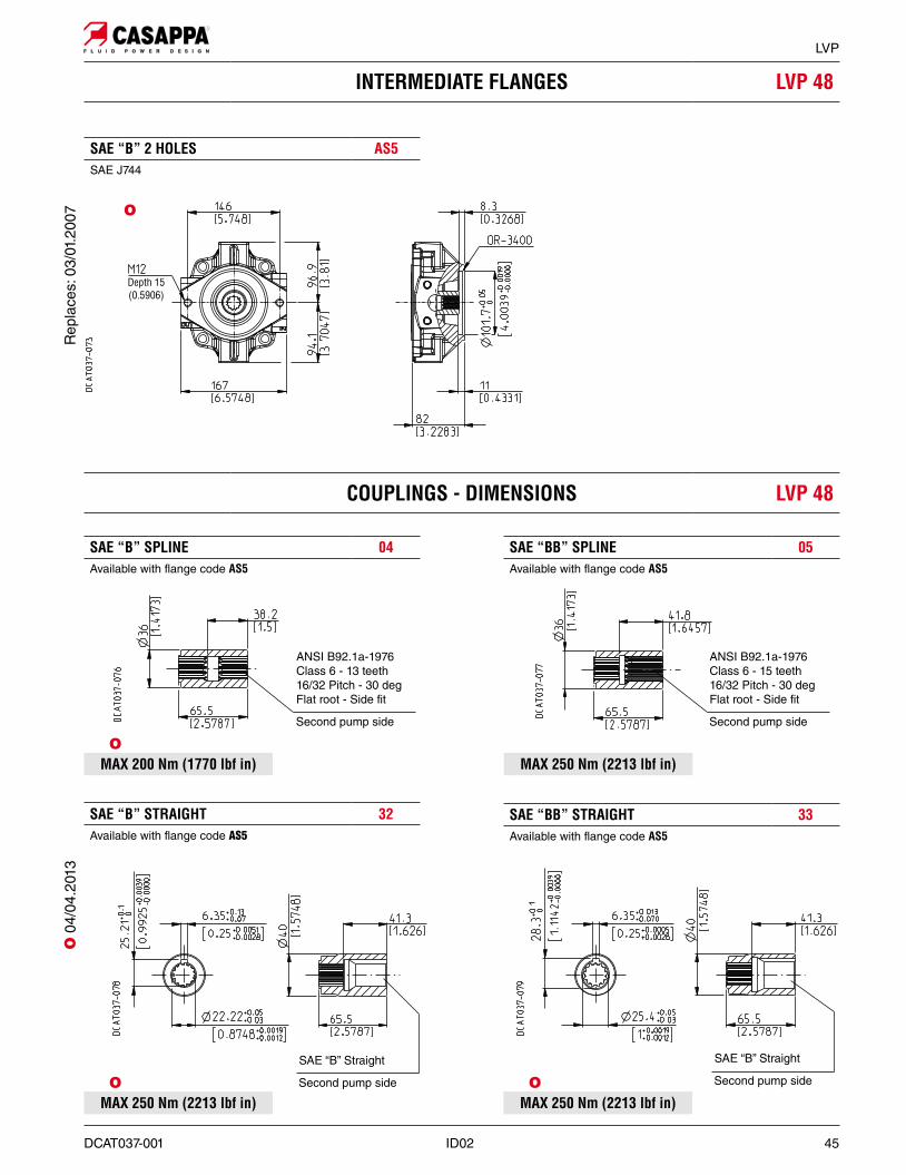
SAE “B” SPLINE 04Available with flange code AS5
INTERMEDIATE FLANGES LVP 48
SAE “BB” STRAIGHT 33Available with flange code AS5
SAE “B” STRAIGHT 32Available with flange code AS5
SAE “BB” SPLINE 05Available with flange code AS5
MAX 250 Nm (2213 lbf in)
SAE “B” 2 HOLES AS5SAE J744
MAX 200 Nm (1770 lbf in)O
MAX 250 Nm (2213 lbf in)O O
MAX 250 Nm (2213 lbf in)
ANSI B92.1a-1976 Class 6 - 13 teeth 16/32 Pitch - 30 deg Flat root - Side fit
Second pump side
ANSI B92.1a-1976 Class 6 - 15 teeth 16/32 Pitch - 30 deg Flat root - Side fit
Second pump side
SAE “B” Straight
Second pump side
SAE “B” Straight
Second pump side
O
COUPLINGS - DIMENSIONS LVP 48
Rep
lace
s: 0
3/01
.200
7O
04/
04.2
013
46 ID02 DCAT037-001
LVP
INTERMEDIATE FLANGES LVP 75 - 90
SAE “A” SPLINE 03Available with flange code AS1
SAE “A” STRAIGHT 31Available with flange code AS1
SAE “A” 2 HOLES AS1SAE J744
COUPLINGS - DIMENSIONS LVP 75 - 90
MAX 100 Nm (885 lbf in)O
MAX 70 Nm (620 lbf in)O
ANSI B92.1a-1976 Class 6 - 9 teeth 16/32 Pitch - 30 deg Flat root - Side fit
Second pump side
SAE “A” Straight
Second pump side
O
O 0
4/04
.201
3R
epla
ces:
03/
01.2
007
DCAT037-001 ID02 47
LVP
INTERMEDIATE FLANGES LVP 75 - 90
SAE “B” SPLINE 04Available with flange code AS5
SAE “B” STRAIGHT 32Available with flange code AS5
SAE “B” 2 HOLES AS5SAE J744
COUPLINGS - DIMENSIONS LVP 75 - 90
SAE “BB” SPLINE 05Available with flange code AS5
SAE “BB” STRAIGHT 33Available with flange code AS5
MAX 200 Nm (1770 lbf in)O
MAX 430 Nm (3806 lbf in)O
MAX 280 Nm (2478 lbf in)O
MAX 250 Nm (2213 lbf in)O
ANSI B92.1a-1976 Class 6 - 13 teeth 16/32 Pitch - 30 deg Flat root - Side fit
Second pump side
SAE “BB” Straight
Second pump side
SAE “B” Straight
Second pump side
ANSI B92.1a-1976 Class 6 - 15 teeth 16/32 Pitch - 30 deg Flat root - Side fit
Second pump side
O
Rep
lace
s: 0
3/01
.200
7O
04/
04.2
013
48 ID02 DCAT037-001
LVP
INTERMEDIATE FLANGES LVP 75 - 90
SAE “C” SPLINE 06Available with flange code AS7
SAE “C” STRAIGHT 34Available with flange code AS7
SAE “C” 2 HOLES AS7SAE J744
COUPLINGS - DIMENSIONS LVP 75 - 90
MAX 430 Nm (3806 lbf in)O
MAX 430 Nm (3806 lbf in)O
ANSI B92.1a-1976 Class 6 - 14 teeth 12/24 Pitch - 30 deg Flat root - Side fit
Second pump side
SAE “C” Stright
Second pump side
O
O 0
4/04
.201
3R
epla
ces:
03/
01.2
007
DCAT037-001 ID02 49
LVP
FRONT SECTION KIT COVER
Kit part brake down1 - Seal2 - Flange3 - Screws
Kit cover is available to obtain single pumps starting from the front sections of multiple pumps.Before closing the intermediate flange check that the coupling has been removed.
Pumptype
A B C Dmm (in) mm (in) Flanged for Code mm (in) mm (in) Kit code
LVP 30 145 (5.7087) 77 (3.0315)SAE A AS1
183 (7.2047)13,4 (0.5276) 62082200
SAE B AS5 14,5 (0.5709) 62082300
LVP 48 169 (6.6535) 82 (3.2283)SAE A AS1
206 (8.1102)13,4 (0.5276) 62082200
SAE B AS5 14,5 (0.5709) 62082300
LVP 75 192 (7.5591)99 (3.8976)
SAE A AS1
235 (9.2520)
13,4 (0.5276) 62082200
SAE B AS5 14,5 (0.5709) 62082300
104 (4.0945) SAE C AS7 17 (0.6693) 62082400
LVP 90 192 (7.5591)99 (3.8976)
SAE A AS1
235 (9.2520)
13,4 (0.5276) 62082200
SAE B AS5 14,5 (0.5709) 62082300
104 (4.0945) SAE C AS7 17 (0.6693) 62082400
Overall dimensions: the same as the single pumps.Ports dimensions at pages 23 ÷ 25. - Screws are supplied with the first pump.
Screws tightening torque Nm (lbf in)
VV1
LVP 30 LVP 48 LVP 75 - LVP 90
70 ±7 (558 ÷ 682) 100 ±10 (797 ÷ 974) 130 ±13 (1036 ÷ 1266) 20 ±1 (159 ÷ 195)
O 0
3/01
.200
7
50 ID02 DCAT037-001
LVP
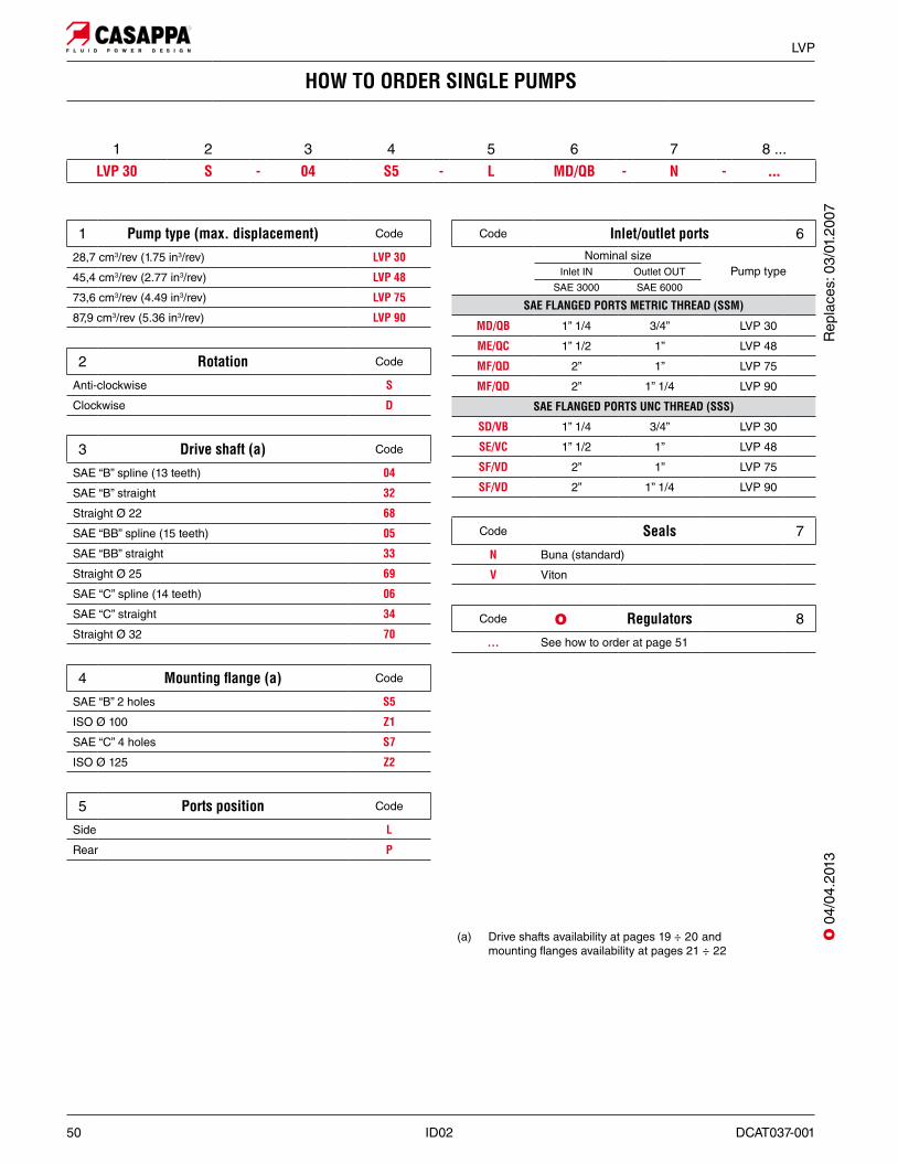
HOW TO ORDER SINGLE PUMPS
1 Pump type (max. displacement) Code
28,7 cm3/rev (1.75 in3/rev) LVP 30
45,4 cm3/rev (2.77 in3/rev) LVP 48
73,6 cm3/rev (4.49 in3/rev) LVP 75
87,9 cm3/rev (5.36 in3/rev) LVP 90
2 Rotation Code
Anti-clockwise S
Clockwise D
3 Drive shaft (a) Code
SAE “B” spline (13 teeth) 04
SAE “B” straight 32
Straight Ø 22 68
SAE “BB” spline (15 teeth) 05
SAE “BB” straight 33
Straight Ø 25 69
SAE “C” spline (14 teeth) 06
SAE “C” straight 34
Straight Ø 32 70
4 Mounting "ange (a) Code
SAE “B” 2 holes S5
ISO Ø 100 Z1
SAE “C” 4 holes S7
ISO Ø 125 Z2
5 Ports position Code
Side L
Rear P
Code Inlet/outlet ports 6Nominal size
Pump typeInlet IN Outlet OUT
SAE 3000 SAE 6000
SAE FLANGED PORTS METRIC THREAD (SSM)
MD/QB 1” 1/4 3/4” LVP 30
ME/QC 1” 1/2 1” LVP 48
MF/QD 2” 1” LVP 75
MF/QD 2” 1” 1/4 LVP 90
SAE FLANGED PORTS UNC THREAD (SSS)
SD/VB 1” 1/4 3/4” LVP 30
SE/VC 1” 1/2 1” LVP 48
SF/VD 2” 1” LVP 75
SF/VD 2” 1” 1/4 LVP 90
Code Seals 7
N Buna (standard)
V Viton
Code Regulators 8
... See how to order at page 51
(a) Drive shafts availability at pages 19 ÷ 20 and mounting flanges availability at pages 21 ÷ 22
1 2 3 4 5 6 7 8 ...LVP 30 S - 04 S5 - L MD/QB - N - ...
O
O 0
4/04
.201
3R
epla
ces:
03/
01.2
007
DCAT037-001 ID02 51
LVP
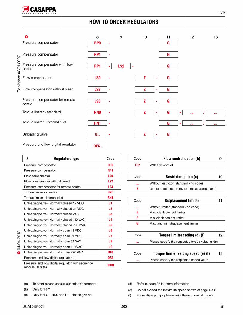
HOW TO ORDER REGULATORS
8 9 10 11 12 13RP0 - G
RP1 - G
RP1 - LS2 - G
LS0 - Z - G
LS2 - Z - G
LS3 - Z - G
RN0 - Z - G - ... / ...
RN1 - G - ... / ...
U.. - Z - G
DES.
8 Regulators type Code
Pressure compensator RP0
Pressure compensator RP1
Flow compensator LS0
Flow compensator without bleed LS2
Pressure compensator for remote control LS3
Torque limiter - standard RN0
Torque limiter - internal pilot RN1
Unloading valve - Normally closed 12 VDC U1
Unloading valve - Normally closed 24 VDC U2
Unloading valve - Normally closed VAC U3
Unloading valve - Normally closed 110 VAC U4
Unloading valve - Normally closed 220 VAC U5
Unloading valve - Normally open 12 VDC U6
Unloading valve - Normally open 24 VDC U7
Unloading valve - Normally open 24 VAC U8
Unloading valve - Normally open 110 VAC U9
Unloading valve - Normally open 220 VAC U10
Pressure and flow digital regulator (a) DES
Pressure and flow digital regulator with sequence module RES (a) DESR
Code Flow control option (b) 9
LS2 With flow control
Code Restrictor option (c) 10
... Without restrictor (standard - no code)
Z Damping restrictor (only for critical applications)
Code Displacement limiter 11
... Without limiter (standard - no code)
E Max. displacement limiter
F Min. displacement limiter
G Max. and min. displacement limiter
Code Torque limiter setting (d) (f) 12
... Please specify the requested torque value in Nm
Code Torque limiter setting speed (e) (f) 13
... Please specify the requested speed value
Pressure compensator
Pressure compensator
Pressure compensator with flow control
Flow compensator
Flow compensator without bleed
Pressure compensator for remote control
Unloading valve
Torque limiter - standard
Torque limiter - internal pilot
(d) Refer to page 32 for more information
(e) Do not exceed the maximum speed shown at page 4 ÷ 6
(f) For multiple pumps please write these codes at the end
(a) To order please consult our sales department
(b) Only for RP1
(c) Only for LS.., RN0 and U.. unloading valve
O
Pressure and flow digital regulator
Rep
lace
s: 0
3/01
.200
7O
04/
04.2
013
52 ID02 DCAT037-001
LVP
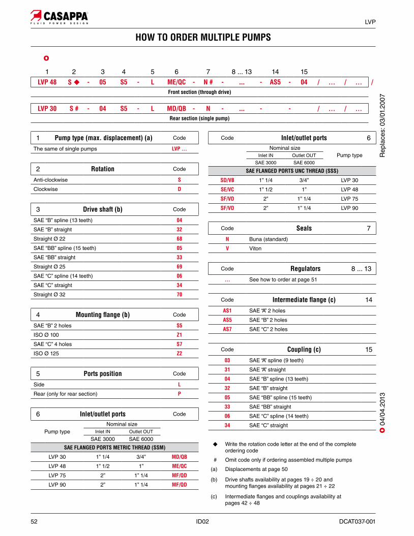
HOW TO ORDER MULTIPLE PUMPS
1 Pump type (max. displacement) (a) Code
The same of single pumps LVP ...
2 Rotation Code
Anti-clockwise S
Clockwise D
3 Drive shaft (b) Code
SAE “B” spline (13 teeth) 04
SAE “B” straight 32
Straight Ø 22 68
SAE “BB” spline (15 teeth) 05
SAE “BB” straight 33
Straight Ø 25 69
SAE “C” spline (14 teeth) 06
SAE “C” straight 34
Straight Ø 32 70
4 Mounting "ange (b) Code
SAE “B” 2 holes S5
ISO Ø 100 Z1
SAE “C” 4 holes S7
ISO Ø 125 Z2
5 Ports position Code
Side L
Rear (only for rear section) P
6 Inlet/outlet ports Code
Pump typeNominal size
Inlet IN Outlet OUT
SAE 3000 SAE 6000
SAE FLANGED PORTS METRIC THREAD (SSM)
LVP 30 1” 1/4 3/4” MD/QB
LVP 48 1” 1/2 1” ME/QC
LVP 75 2” 1” 1/4 MF/QD
LVP 90 2” 1” 1/4 MF/QD
1 2 3 4 5 6 7 8 ... 13 14 15
LVP 48 S � - 05 S5 - L ME/QC - N # - ... - AS5 - 04 / ... / ... /Front section (through drive)
LVP 30 S # - 04 S5 - L MD/QB - N - ... - - / ... / ...Rear section (single pump)
� Write the rotation code letter at the end of the complete ordering code
# Omit code only if ordering assembled multiple pumps
(a) Displacements at page 50
(b) Drive shafts availability at pages 19 ÷ 20 and mounting flanges availability at pages 21 ÷ 22
(c) Intermediate flanges and couplings availability at pages 42 ÷ 48
Code Inlet/outlet ports 6Nominal size
Pump typeInlet IN Outlet OUT
SAE 3000 SAE 6000
SAE FLANGED PORTS UNC THREAD (SSS)
SD/VB 1” 1/4 3/4” LVP 30
SE/VC 1” 1/2 1” LVP 48
SF/VD 2” 1” 1/4 LVP 75
SF/VD 2” 1” 1/4 LVP 90
Code Seals 7
N Buna (standard)
V Viton
Code Regulators 8 ... 13
... See how to order at page 51
Code Intermediate "ange (c) 14
AS1 SAE “A” 2 holes
AS5 SAE “B” 2 holes
AS7 SAE “C” 2 holes
Code Coupling (c) 15
03 SAE “A” spline (9 teeth)
31 SAE “A” straight
04 SAE “B” spline (13 teeth)
32 SAE “B” straight
05 SAE “BB” spline (15 teeth)
33 SAE “BB” straight
06 SAE “C” spline (14 teeth)
34 SAE “C” straight
O
O 0
4/04
.201
3R
epla
ces:
03/
01.2
007
DCAT037-001 ID02 53
LVP
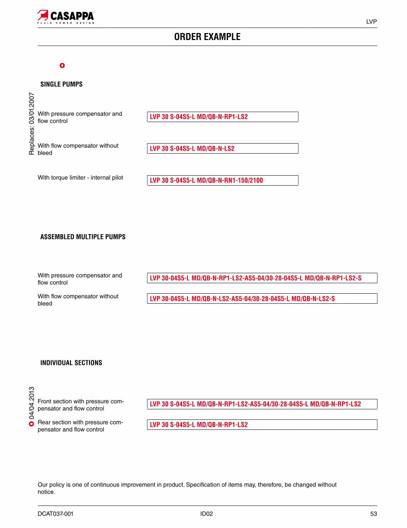
ORDER EXAMPLE
SINGLE PUMPS
LVP 30-04S5-L MD/QB-N-RP1-LS2-AS5-04/30·28-04S5-L MD/QB-N-RP1-LS2-S
LVP 30-04S5-L MD/QB-N-LS2-AS5-04/30·28-04S5-L MD/QB-N-LS2-S
With pressure compensator and flow control
With flow compensator without bleed
LVP 30 S-04S5-L MD/QB-N-RP1-LS2
LVP 30 S-04S5-L MD/QB-N-LS2
LVP 30 S-04S5-L MD/QB-N-RN1-150/2100
With pressure compensator and flow control
With flow compensator without bleed
With torque limiter - internal pilot
ASSEMBLED MULTIPLE PUMPS
O
Our policy is one of continuous improvement in product. Specification of items may, therefore, be changed without notice.
Rep
lace
s: 0
3/01
.200
7O
04/
04.2
013
LVP 30 S-04S5-L MD/QB-N-RP1-LS2-AS5-04/30·28-04S5-L MD/QB-N-RP1-LS2
LVP 30 S-04S5-L MD/QB-N-RP1-LS2
Front section with pressure com-pensator and flow control
Rear section with pressure com-pensator and flow control
INDIVIDUAL SECTIONS

Edition: 04/04.2013LVP 04 T A Replaces: LVP 03 T A
VARIABLE DISPLACEMENT AXIAL PISTON PUMPS
LVP SERIES
Headquarters:
CASAPPA S.p.A.Via Balestrieri, 1
43044 Lemignano di Collecchio
Parma (Italy)
Tel. (+39) 0521 30 41 11
Fax (+39) 0521 80 46 00
IP VideoconferencingE-mail: [email protected]