Valves
69
VALVES III Year VI Sem Automation Laboratory Department of Mechanical Engineering SRM UNIVERSITY
-
Upload
kshitij-sharma -
Category
Documents
-
view
213 -
download
0
description
valves fluid mechanics
Transcript of Valves

VALVES
III Year VI Sem
Automation Laboratory Department of Mechanical Engineering
SRM UNIVERSITY
Hydraulic Valves
• Direction control valve• Pressure control valve• Flow control valve• Servo valve• Proportional control valve• Cartridge valve

Direction Control Valve
• Direction control valve is used to control the direction of the flow in a hydraulic/ pneumatic circuits
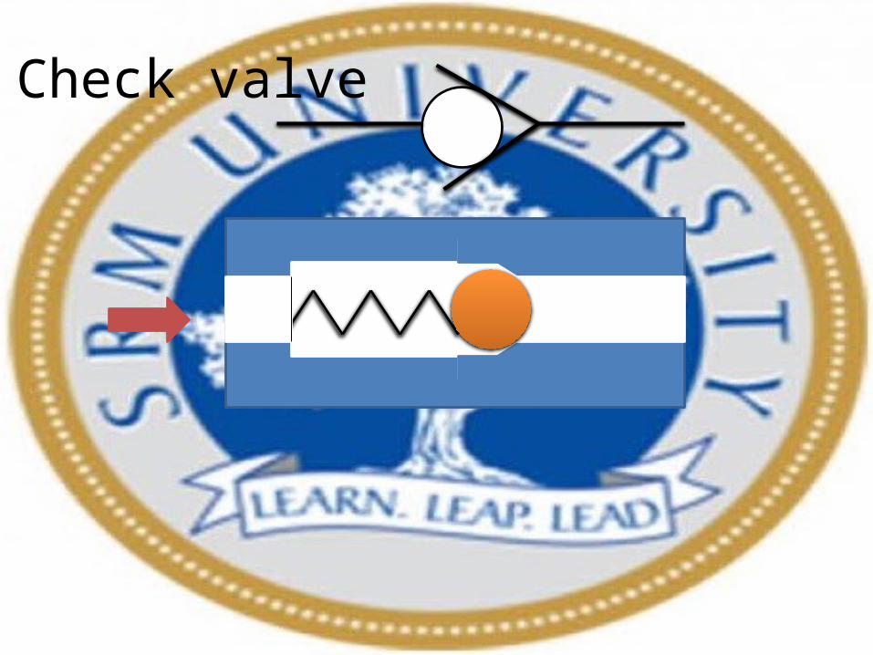
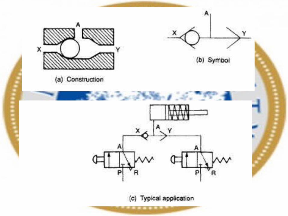
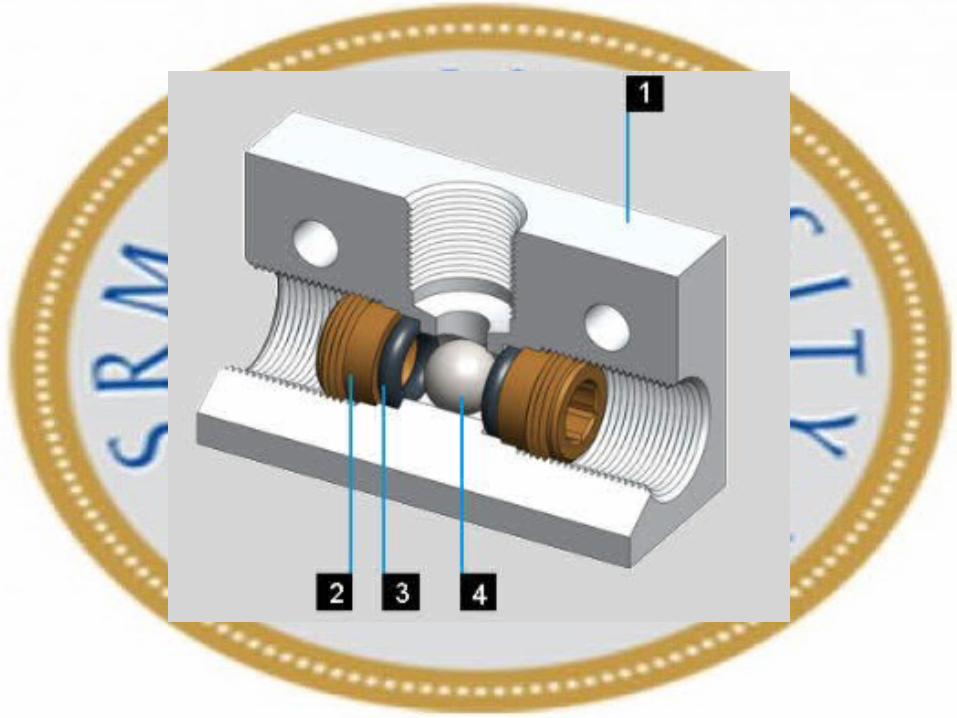
Check valve
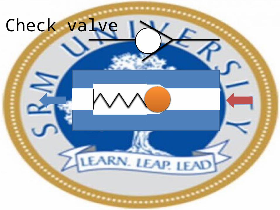
Check valve

Check valve

Pilot operated Check valve


Shuttle Valve

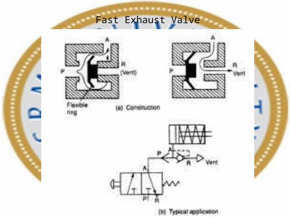
Fast Exhaust Valve
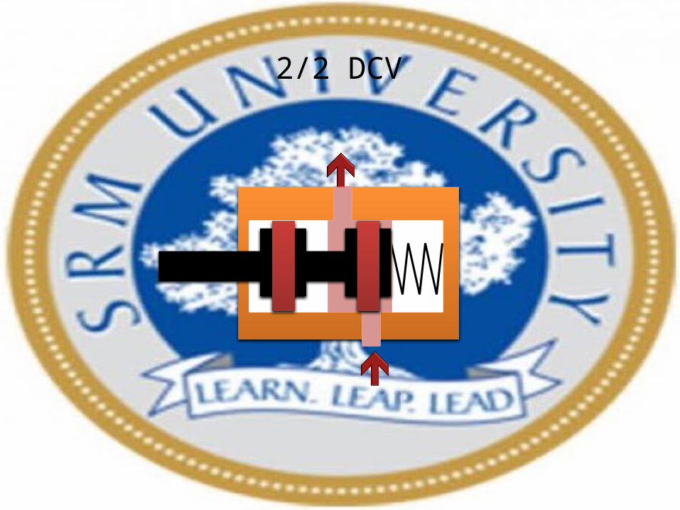
2/2 DCV

3/2 DCV

4/2 DCV

4/2 DCV

5/2 DCV

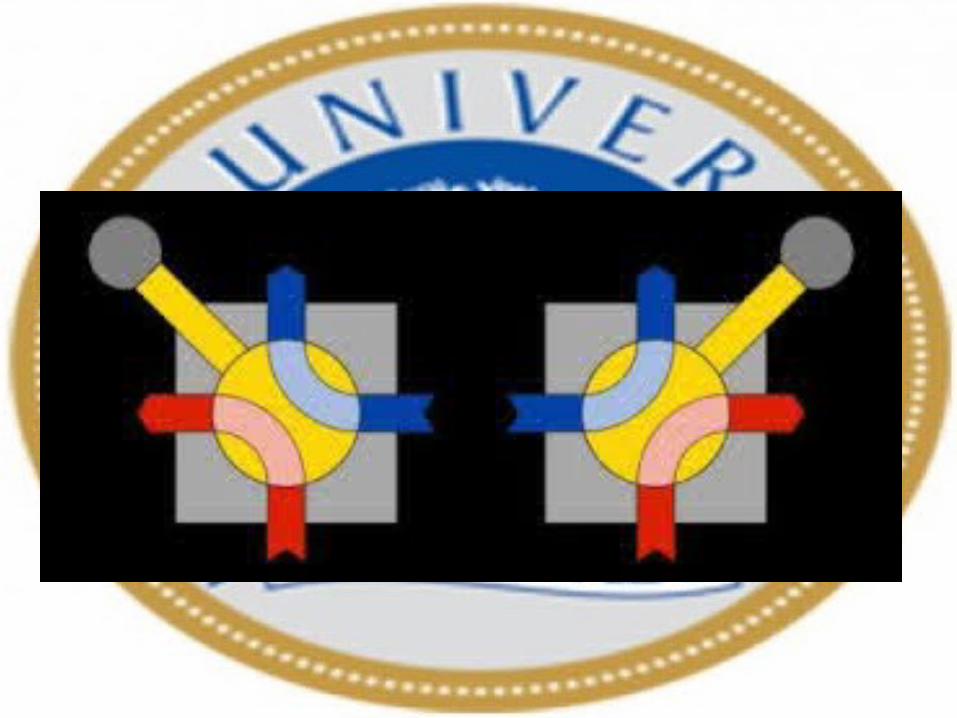
Rotary Four-way valve


Pressure-control valves are used in hydraulic systems to control actuator force (force = pressure × area)and to determine and select pressure levels at which certain machine operations must occur.
Pressure Control Valve:
• Limiting maximum system pressure at a safe level.• Regulating/reducing pressure in certain portions of the circuit.• Unloading system pressure.• Assisting sequential operation of actuators in a circuit with pressure control.• Any other pressure-related function by virtue of pressure control.• Reducing or stepping down pressure levels from the main circuit to a lower pressure in a •sub-circuit.
Functions of Pressure control valve:
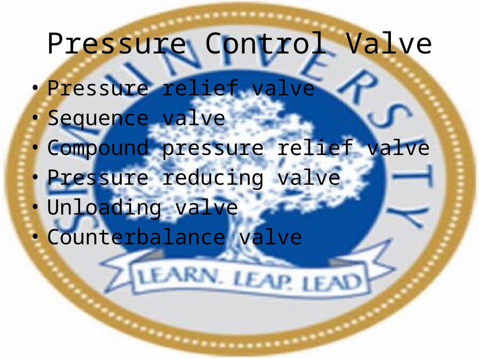
Pressure Control Valve• Pressure relief valve• Sequence valve• Compound pressure relief valve• Pressure reducing valve• Unloading valve• Counterbalance valve
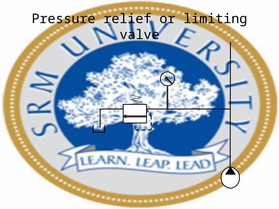
Pressure relief or limiting valve
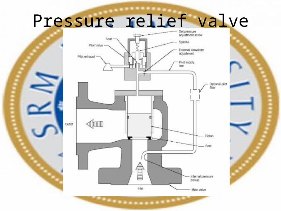
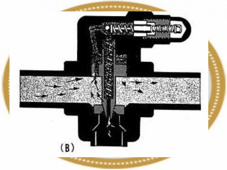
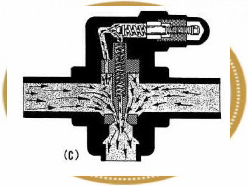
Pressure relief valve

Sequence valve


Compound pressure relief valve


Unloading Valve

Unloading valves are pressure-control devices that are used to dump excess fluid to the tank at little or no pressure. A common application is in high-low pump circuits where two pumps move an actuator at a high speed and low pressure.
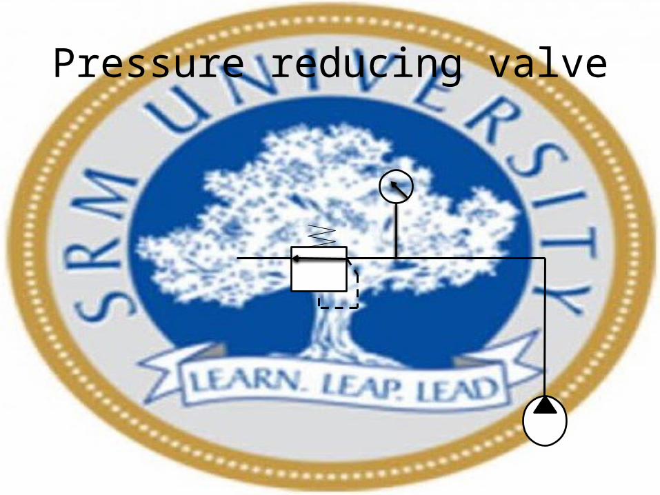
Pressure reducing valve
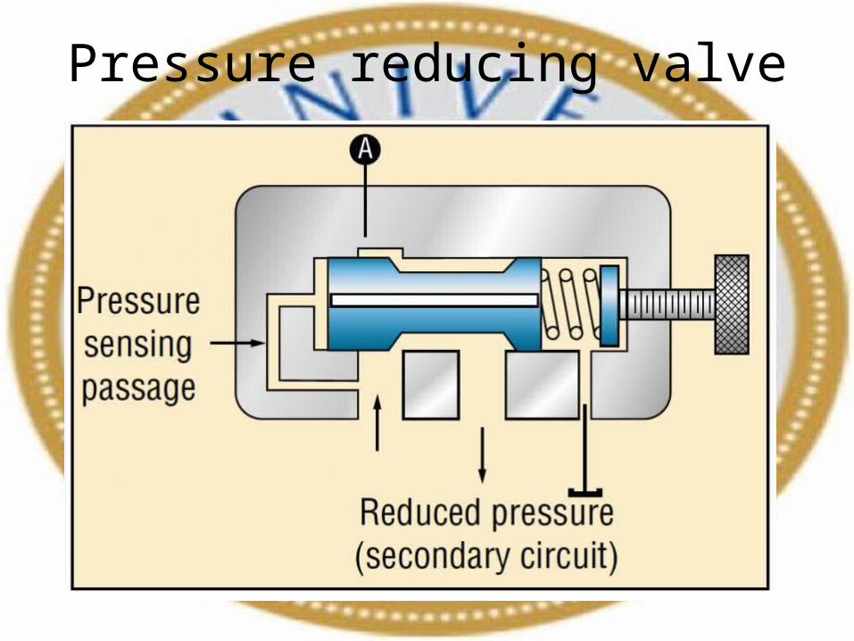
Pressure reducing valve
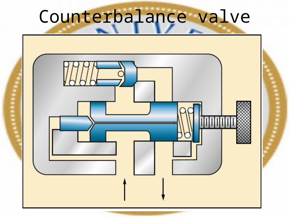
Counterbalance valve


Flow control valve


Classification of Flow-Control Valves Flow-control valves can be classified as follows:1. Non-pressure compensated.2. Pressure compensated
Non-Pressure-Compensated Valves:
Non-pressure-compensated flow-control valves are used when the system pressure is relatively constant and motoring speeds are not too critical. The operating principle behind these valves is that the flow through an orifice remains constant if the pressure drop across it remains the same. In other words, the rate of flow through an orifice depends on the pressure drop across it.


Pressure-Compensated Valves
Pressure-compensated flow-control valves overcome the difficulty caused by non-pressure compensated valves by changing the size of the orifice in relation to the changes in the system pressure. This is accomplished through a spring-loaded compensator spool that reduces the size of the orifice when pressure drop increases. Once the valve is set, the pressure compensator acts to keep the pressure drop nearly constant. It works on a kind of feedback mechanism from the outlet pressure. This keeps the flow through the orifice nearly constant

Sealing Most Widely used type of seals• O-rings• Compression packed (V and U- shape)• Piston cap Packing• Piston rings• Wiper rings

O-rings

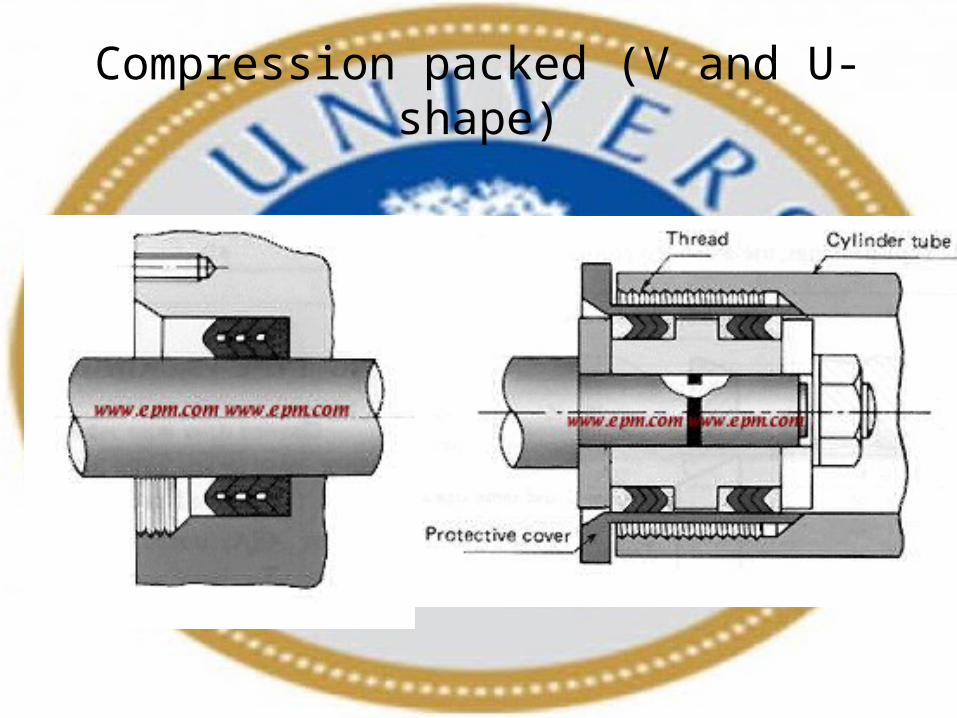
Compression packed (V and U- shape)

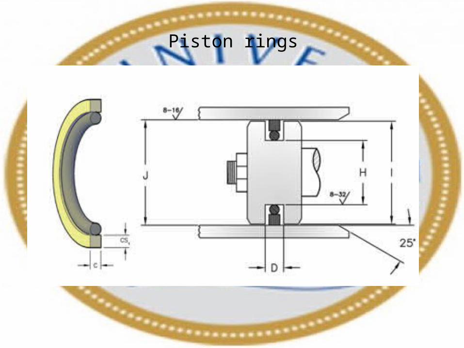
Piston rings
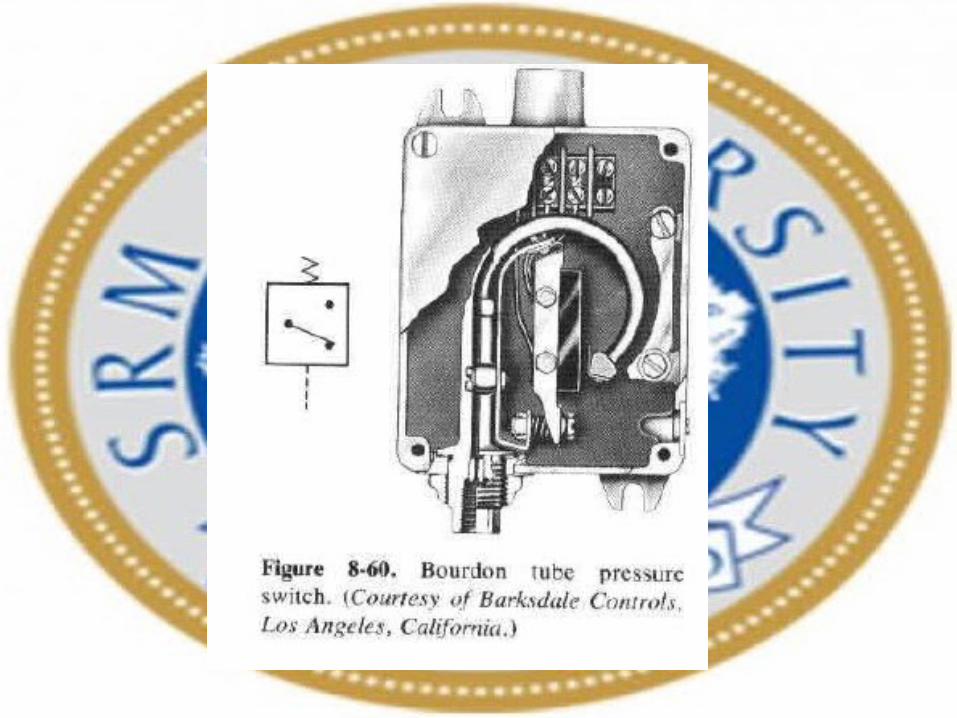
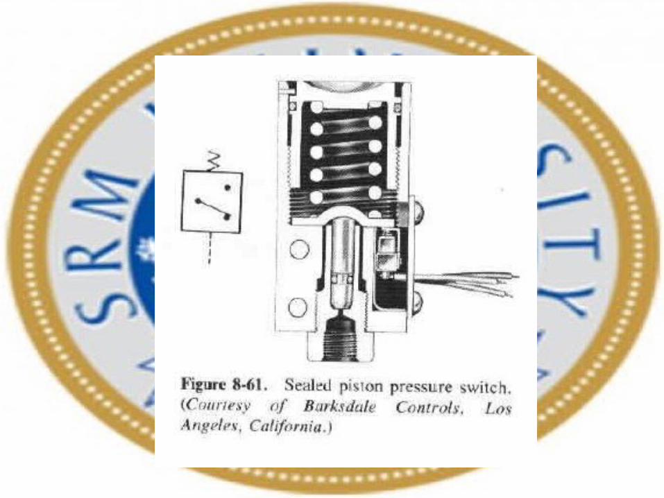
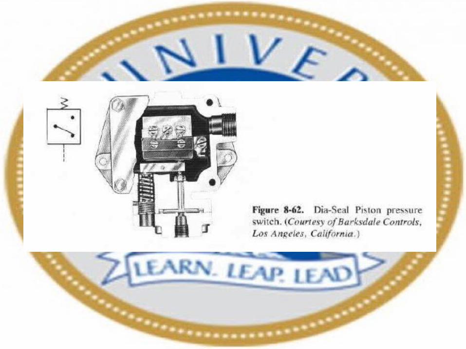
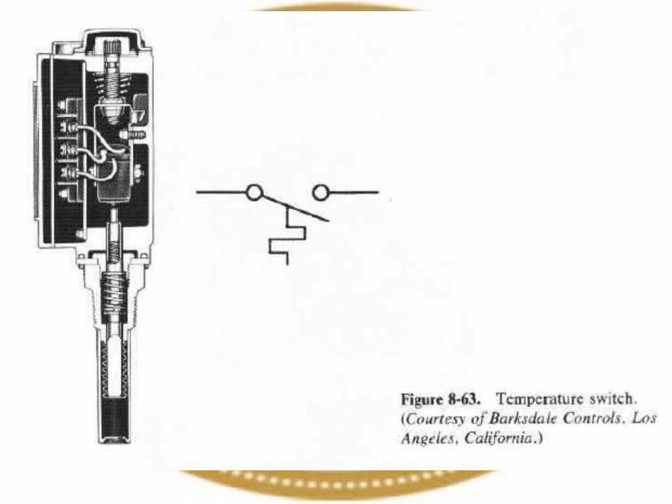
PRESSURE SWITCHES:
Types:1. Diaphragm2. Bourdon tube3. Sealed piston4. Dia- seal piston
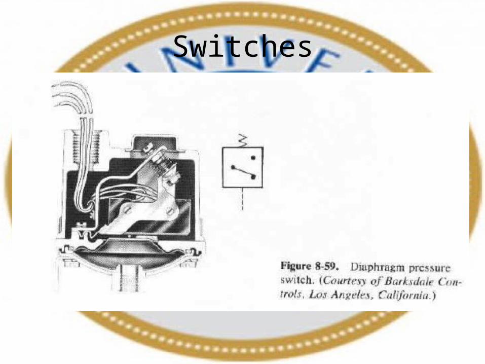
Switches


ACCUMULATORS:
A hydraulic accumulator is a device that stores the potential energy of an incompressible fluid held under pressure by an external source against some dynamic force. This dynamic force can come from different sources. The stored potential energy in the accumulator is a quick secondary source of fluid power capable of doing useful work.
There are three basic types of accumulators:1. Weight-loaded or gravity accumulator: It is a vertically mounted cylinder with a large weight. When the hydraulic fluid is pumped into it, the weight is raised. The weight applies a force on the piston that generates a pressure on the fluid side of piston.
The advantage of this type of accumulator over other types is that it applies a constant on the fluid throughout its range of motion
The main disadvantage is its extremely large size and heavy weight. This makes it unsuitable for mobile application.
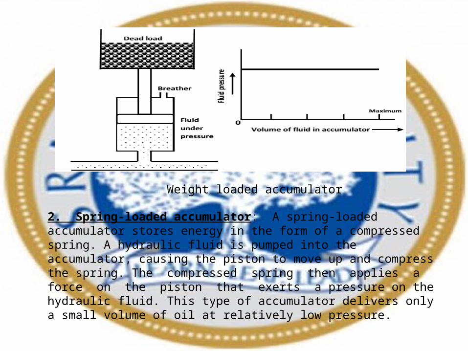
Weight loaded accumulator
2. Spring-loaded accumulator: A spring-loaded accumulator stores energy in the form of a compressed spring. A hydraulic fluid is pumped into the accumulator, causing the piston to move up and compress the spring. The compressed spring then applies a force on the piston that exerts a pressure on the hydraulic fluid. This type of accumulator delivers only a small volume of oil at relatively low pressure.

Spring loaded accumulator
3. Gas-loaded accumulator: A gas-loaded accumulator is popularly used in industries. Here the force is applied to the oil using compressed air. A gas accumulator can be very large and is often used with water or high water-based fluids using air as a gas charge. Typical application is on water turbines to absorb pressure surges owing to valve closure and on ram pumps to smooth out the delivery flow.
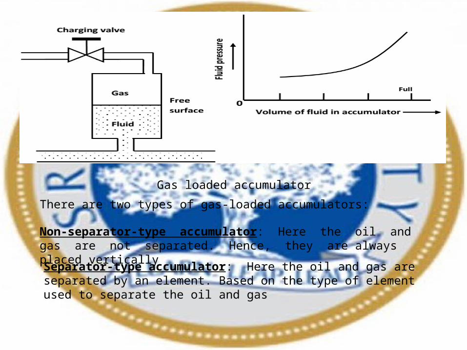
Gas loaded accumulator
There are two types of gas-loaded accumulators:
Non-separator-type accumulator: Here the oil and gas are not separated. Hence, they are always placed vertically
Separator-type accumulator: Here the oil and gas are separated by an element. Based on the type of element used to separate the oil and gas

(a) Piston-type accumulator: It consists of a cylinder with a freely floating piston with proper seals. Its operation begins by charging the gas chamber with a gas (nitrogen) under a pre-determined pressure. This causes the free sliding piston to move down. Once the accumulator is pre-charged, a hydraulic fluid can be pumped into the hydraulic fluid port. As the fluid enters the accumulator, it causes the piston to slide up, thereby compressing the gas that increases its pressure and this pressure is then applied to the hydraulic fluid through the piston. Because the piston is free sliding, the pressure on the gas and that on the hydraulic fluid are always equal.
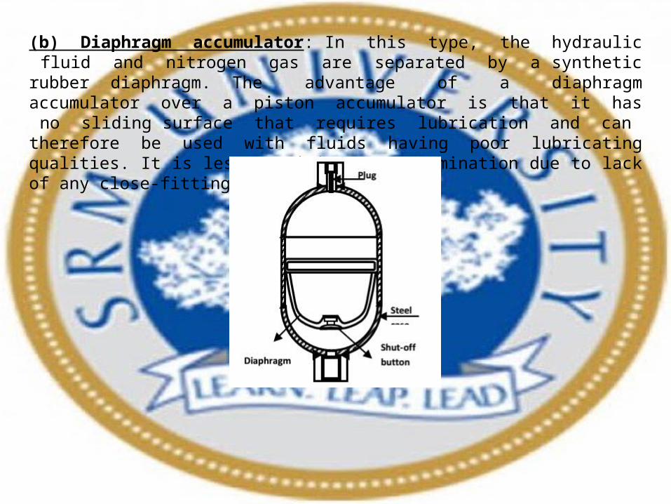
(b) Diaphragm accumulator: In this type, the hydraulic fluid and nitrogen gas are separated by a synthetic rubber diaphragm. The advantage of a diaphragm accumulator over a piston accumulator is that it has no sliding surface that requires lubrication and can therefore be used with fluids having poor lubricating qualities. It is less sensitive to contamination due to lack of any close-fitting components.
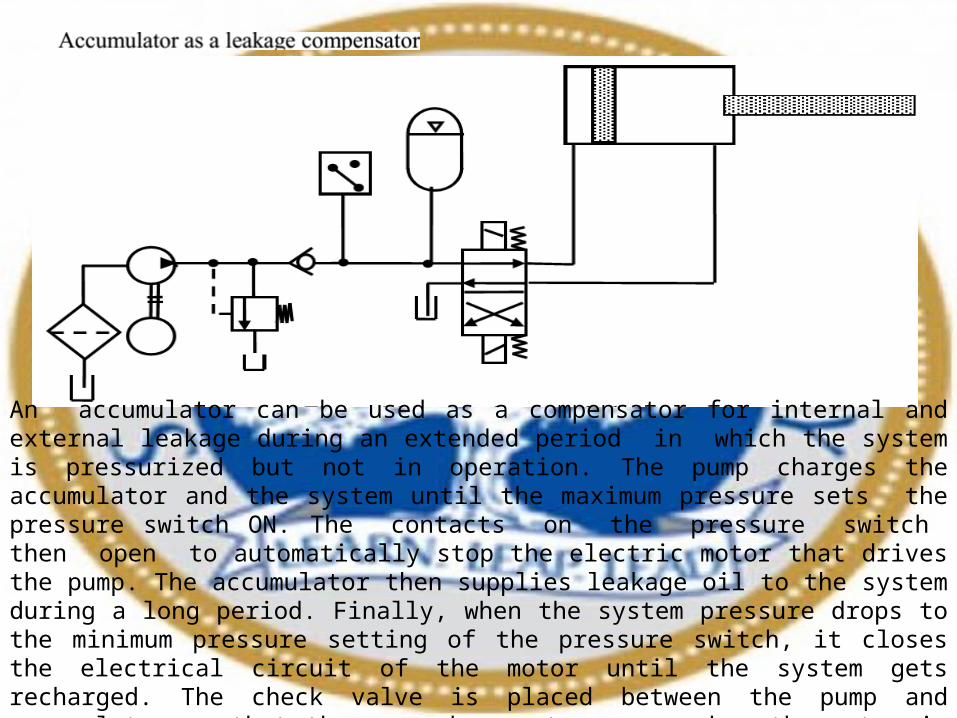
An accumulator can be used as a compensator for internal and external leakage during an extended period in which the system is pressurized but not in operation. The pump charges the accumulator and the system until the maximum pressure sets the pressure switch ON. The contacts on the pressure switch then open to automatically stop the electric motor that drives the pump. The accumulator then supplies leakage oil to the system during a long period. Finally, when the system pressure drops to the minimum pressure setting of the pressure switch, it closes the electrical circuit of the motor until the system gets recharged. The check valve is placed between the pump and accumulator so that the pump does not reverse when the motor is stopped and does not permit all the accumulator charge to drain back into the power unit. With this circuit, the only time the power unit operates is when the pressure drops to an unsafe operating level. This saves electric power and reduces the heat in the system.
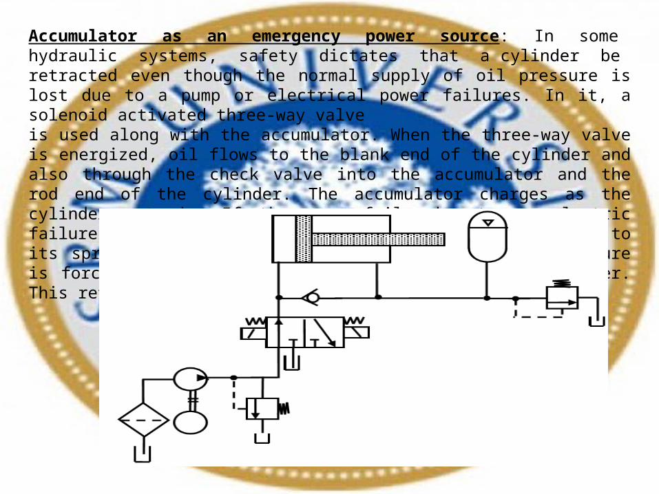
Accumulator as an emergency power source: In some hydraulic systems, safety dictates that a cylinder be retracted even though the normal supply of oil pressure is lost due to a pump or electrical power failures. In it, a solenoid activated three-way valve is used along with the accumulator. When the three-way valve is energized, oil flows to the blank end of the cylinder and also through the check valve into the accumulator and the rod end of the cylinder. The accumulator charges as the cylinder extends. If the pump fails due to an electric failure, the solenoid de-energizes, shifting the valve to its spring offset mode. Then the oil stored under pressure is forced from the accumulator to the end of the cylinder. This retracts the cylinder to its starting position.

Accumulator as a hydraulic shock absorber: One of the important applications of accumulators is the elimination of hydraulic shock. Hydraulic shock is caused by the sudden stoppage or declaration of a hydraulic fluid flowing at relatively high velocity in a pipe line. Rapidly closing a valve creates a compression wave. This compression wave travels at the speed of sound upstream to the end of the pipe and back again to the closed valve, which causes an increase in pressure. The resulting rapid pressure pulsations or high-pressure surges may cause damage to the hydraulic system components. If an accumulation is installed near the rapidly closing valve, the pressure pulsations or high pressure surges are suppressed.
What size of accumulator is necessary to supply 10000 cm³ of fluid is a hydraulic system of maximum pressure of 200 bar to 100 bar minimum. Assuming N2 gas per-charged pressure of 80 bar. Find adiabatic and isothermal solution.
SERVO VALVES: Servo valves were developed to facilitate the adjustment of fluid flow based on changes in the load motion. Simply put, it is a programmable orifice. In machine motion control, servo systems involve continuous monitoring, feedback and correction. Also they are used to improve efficiency, accuracy and repeatability.
A servomechanism is defined as an automatic device for controlling a large amount of power by means of a very small amount of power and automatically correcting the performance of a mechanism.
Servo ValvesServo valves can be used in virtually any aspect of fluid power system operations, including the following:
1. Positioning of cylinders and rotary actuators.2. Speed of cylinders and motors.3. Cylinder force and motor torque.4. Acceleration and deceleration.5. System pressure.6. Flow rate.