Valmont India - Utility
32
1 Valmont India - Utility UTILITY POLES
Transcript of Valmont India - Utility

1
Valmont India - Utility
� UTILITY POLES

2
Introduction to Utility Poles
� Traditionally lattice towers common for high voltage transmission lines.
� Use of steel poles started in late 1960s in US with extensive research,
engineering and testing in early stages.
� Received wider acceptance in 70s & 80s. Valmont one of pioneers in
design and manufacturing.
� Today steel poles are the dominant type structures for new age power
transmission & are commonly used in many countries, being adopted in
more new markets. Valmont has solid business experience world wide
and a pioneer in India.
400 kV D/C Pole V/S 400 kV D/C Tower - KPTCL
3
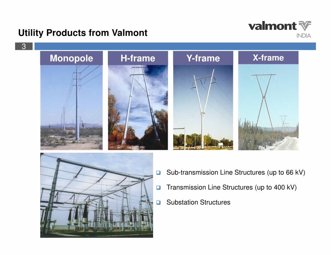
Utility Products from Valmont
Monopole H-frame Y-frame
� Sub-transmission Line Structures (up to 66 kV)
� Transmission Line Structures (up to 400 kV)
� Substation Structures
X-frame
4
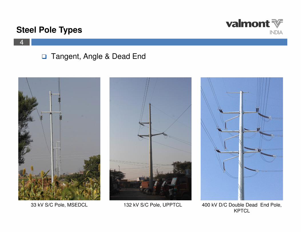
Steel Pole Types
� Tangent, Angle & Dead End
33 kV S/C Pole, MSEDCL 132 kV S/C Pole, UPPTCL 400 kV D/C Double Dead End Pole,
KPTCL

5
Steel Pole Advantages
� Less right-of-way
� Better appearance
� Less components & fast installation
� Better reliability under extreme conditions
� Flexibility in design
� Reliable performance and long service life
400/220 kV M/C Pole, KPTCL

6
Less Right of Way
� Smaller foundation takes less land
� Self supporting poles. No Stays or Strut structures required
� Efficiently placed along Highways, Road dividers, Rail tracks, etc.
� Can be installed at locations with very limited space
132 kV S/C Pole, RRVPNL 132 kV S/C Pole, UPPTCL 110 kV D/C Pole, TNEB 400/220 kV M/C Pole, KPTCL

7
Better Appearance
� Remove “visual” pollution
� Structure compatible with environment
� Bulky clutter lattice tower visually unpleasant
132 kV S/C Pole, UPPTCL 132 kV D/C Pole, RRVPNL 132 kV D/C Pole, MSETCL 220 kV D/C Pole, KPTCL
8
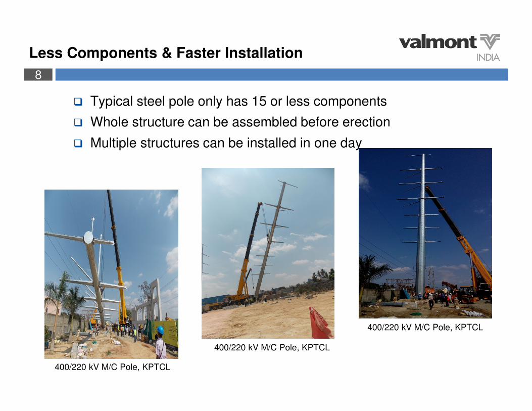
Less Components & Faster Installation
� Typical steel pole only has 15 or less components
� Whole structure can be assembled before erection
� Multiple structures can be installed in one day
400/220 kV M/C Pole, KPTCL
400/220 kV M/C Pole, KPTCL
400/220 kV M/C Pole, KPTCL

9
Better Reliability under Extreme Conditions
� Steel monopoles are more flexible than lattice towers, concrete or other steel structures under heavy loads
� In broken conductor case, bigger deflection of the steel pole reduces tension in intact span and induces smaller bending moment at base
� Round or multi-side profile induces less wind load
� In past cases where lattice towers and steel poles structures failed in severe wind storms, no steel poles were damaged
� Reliable performance and long service life with zero maintenance

10
Flexibility in Design
� Various structure
� Different voltages grades and multiple circuits on same pole
� Distribution under-built
� Multiple circuits in different orientation
� With extensions dealing with elevations/undulations becomes easy
400 kV DDE (900) & 220 kV NH
Crossing M/C Pole, KPTCL
220 kV D/C Pole with vertical cross arm
arrangement, KPTCL400 kV DDE (900) NH Crossing
D/C Pole, KPTCL
11
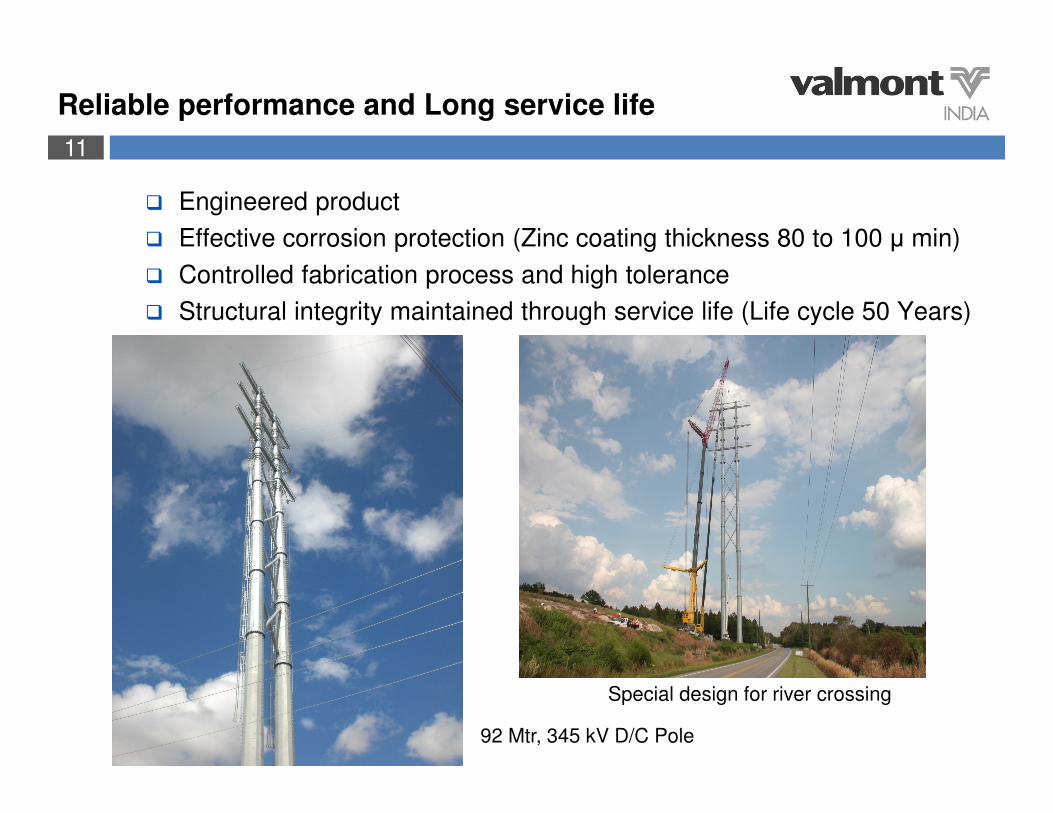
Reliable performance and Long service life
� Engineered product
� Effective corrosion protection (Zinc coating thickness 80 to 100 µ min)
� Controlled fabrication process and high tolerance
� Structural integrity maintained through service life (Life cycle 50 Years)
92 Mtr, 345 kV D/C Pole
Special design for river crossing
12
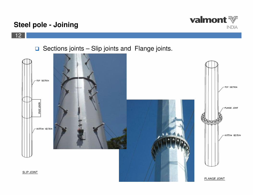
Steel pole - Joining
� Sections joints – Slip joints and Flange joints.

13
Steel pole - Other Arrangements
� Climbing arrangements with step bolts.
� Anti climbing arrangement.
14
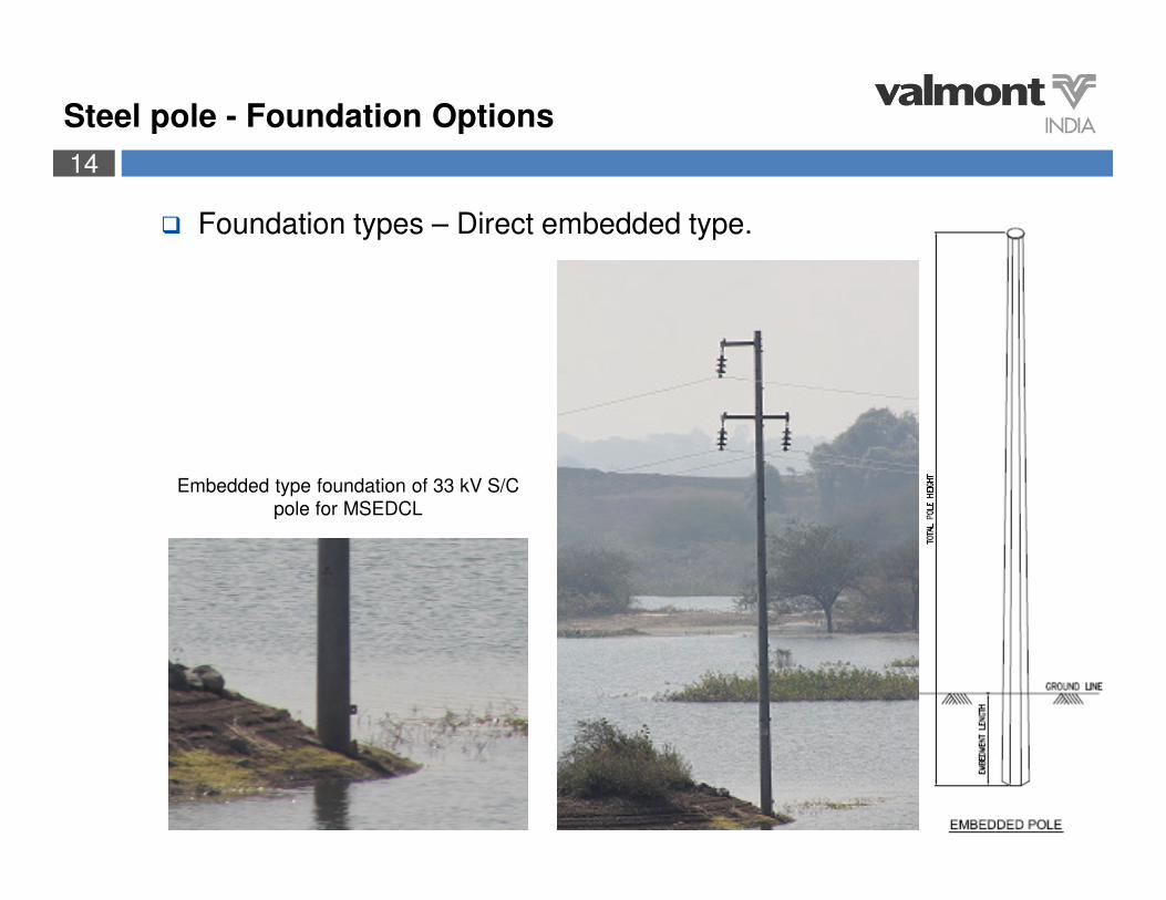
� Foundation types – Direct embedded type.
Embedded type foundation of 33 kV S/C
pole for MSEDCL
Steel pole - Foundation Options

15
� Foundation types – Concrete foundations with anchor bolts.
400/220 kV M/C pole for KPTCL
(Before & After casting)
132 kV D/C pole for MSETCL
(Before casting)
Steel pole - Foundation Options

16
Steel pole - Foundation Options
� Foundation types – Concrete foundations with anchor bolts.
132 kV D/C pole for RRVPNL
(Before & After casting)
132 kV S/C pole for UPPTCL
17
.
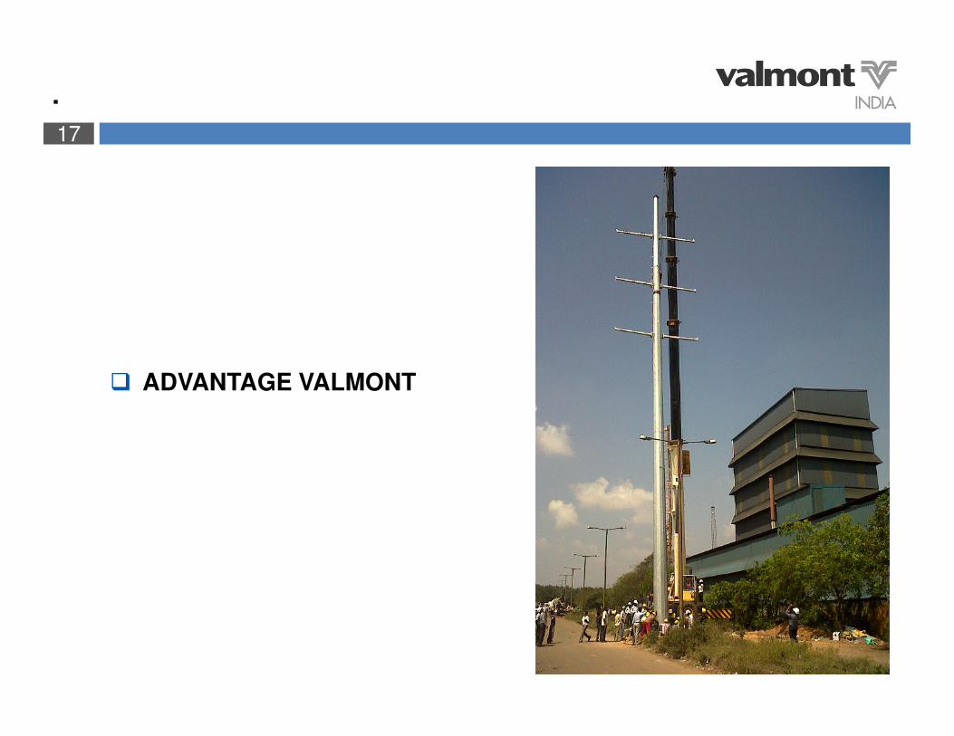
� ADVANTAGE VALMONT
18
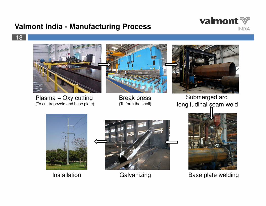
Valmont India - Manufacturing Process
Plasma + Oxy cutting(To cut trapezoid and base plate)
Break press(To form the shell)
Submerged arc
longitudinal seam weld
Base plate weldingGalvanizingInstallation
19
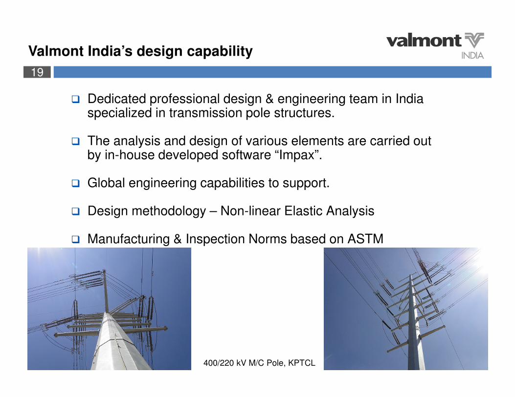
� Dedicated professional design & engineering team in India specialized in transmission pole structures.
� The analysis and design of various elements are carried out by in-house developed software “Impax”.
� Global engineering capabilities to support.
� Design methodology – Non-linear Elastic Analysis
� Manufacturing & Inspection Norms based on ASTM
400/220 kV M/C Pole, KPTCL
Valmont India’s design capability

20
� 400 kV DC & 220 kV DC pole for KPTCL and 132 kV DC poles for UETCL - full scale test in L&T test centre - Chennai
Type Test in India

21
Type Test in India
� 132 kV DC pole full scale test for MSETCL – CPRI, Bangalore

22
Valmont India – Full scale type test reference
FULL SCALE TYPE TEST REFERENCE LIST
End Customer
Project NamePole
Height (Mtr)
Pole Black
Weight (MT)
Voltage & Ckt TypeTest Pole
QuantityDate of Test Test Report No. & Date
MSETCL132 kV D/C line height raising project
23.93 3.06 132 kV D/CDA+3
(0-2 Deg)1 23/12/2012
CPRI/MED/TTS/2012/S24/VI/T-28/2012-13, 11th Jan’ 2013
KPTCL 66 kV D/C line diversion project 31.55 7.94 66 kV D/C Dead end 1 6/7/2013CPRI/MED/TTS/2013/S5/GK/T-9/2013-14, 11th July’2013
KPTCL400 kV & 220 kV line diversion project
44.1 15.99 400 kV D/C DY-50 1 28.09.2013L&T/TLTRS/FR/FR/DY/DC/134
UETCL MBRA-NKDA new line 29.1 8.39 132 kV D/C DTA15 1 5/10/2013 L&T/TLTRS/FR/FR/DC/130
UETCL MBRA-NKDA new line 29.43 7.10 132 kV D/CDS1
(Revision)1 21/11/2013 L&T/TLTRS/FR/FR/DC/139
UETCL MBRA-NKDA new line 29.1 15.68 132 kV D/C DTA 60 129th & 30th
Nov’2013L&T/TLTRS/FR/FR/DC/140
UETCL MBRA-NKDA new line 29.1 19.82 132 kV D/C DTA 90 1 3/12/2013 L&T/TLTRS/FR/FR/DC/141
TATA Power
220 kV Trombay - SalsetteTransmission Line
14.43 2.70 220 kV M/C DF+5 Model 1 30/1/2014L&T/TLTRS/KPM/TR/DF+5/MP/MC/129-01/2014 Dtd-6th Feb’2014.
KPTCL 220 kV Line diversion project 37.57 12.20 220 kV D/CDSX-1
(42 Deg)1 17/05/2014
L&T/TLTRS/FR/VALMONT-DSX1/DC/158Dtd - 17/05/2015
23
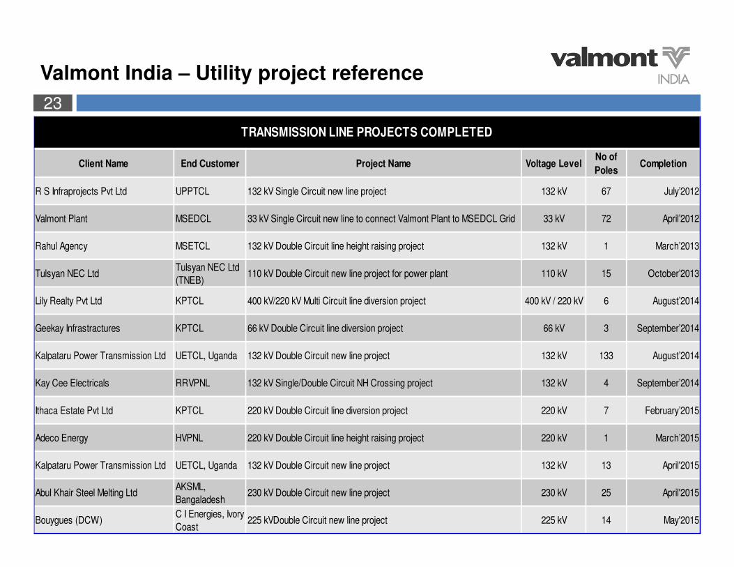
Valmont India – Utility project reference
Client Name End Customer Project Name Voltage LevelNo of
PolesCompletion
R S Infraprojects Pvt Ltd UPPTCL 132 kV Single Circuit new line project 132 kV 67 July’2012
Valmont Plant MSEDCL 33 kV Single Circuit new line to connect Valmont Plant to MSEDCL Grid 33 kV 72 April’2012
Rahul Agency MSETCL 132 kV Double Circuit line height raising project 132 kV 1 March’2013
Tulsyan NEC LtdTulsyan NEC Ltd
(TNEB)110 kV Double Circuit new line project for power plant 110 kV 15 October’2013
Lily Realty Pvt Ltd KPTCL 400 kV/220 kV Multi Circuit line diversion project 400 kV / 220 kV 6 August’2014
Geekay Infrastractures KPTCL 66 kV Double Circuit line diversion project 66 kV 3 September’2014
Kalpataru Power Transmission Ltd UETCL, Uganda 132 kV Double Circuit new line project 132 kV 133 August’2014
Kay Cee Electricals RRVPNL 132 kV Single/Double Circuit NH Crossing project 132 kV 4 September’2014
Ithaca Estate Pvt Ltd KPTCL 220 kV Double Circuit line diversion project 220 kV 7 February’2015
Adeco Energy HVPNL 220 kV Double Circuit line height raising project 220 kV 1 March’2015
Kalpataru Power Transmission Ltd UETCL, Uganda 132 kV Double Circuit new line project 132 kV 13 April'2015
Abul Khair Steel Melting LtdAKSML,
Bangaladesh230 kV Double Circuit new line project 230 kV 25 April'2015
Bouygues (DCW)C I Energies, Ivory
Coast225 kVDouble Circuit new line project 225 kV 14 May'2015
TRANSMISSION LINE PROJECTS COMPLETED

24
.
� POLE vs TOWER

25
Comparison of transmission Tower & Monopole
TRANSMISSION STRUCTURES
Sl No PARTICULAR LATTICE STRUCTURE MONOPOLES
1 Ground Surface / Footprint More Less
Typical example Around 10 Mtr x10 Mtr
(for 132 kV)
Less than 2 Mtr base diameter
Around 30 Mtr x 30 Mtr
(for 400 kV)
Around 2 Mtr base diameter
2 Right of Way issue More due to wider footprint Lesser due to narrow footprint
Broader corridor Needs narrower corridor
3 Appearance Bulky clutter / Untidy Better appearance
4 Installation time Longer time Fast
Typical example 6-7 days post foundation 1 day post foundation
5 (a) Structural Model 3-D truss Cantilever beam
5 (b) Main force in action Tension & compression Bending movment
5 (c) Deflection Less Can take more deflections
6 Reliability in extreme condition Higher risk of collapse Comparatively much safer
7 Vandalism / Theft Higher risk
(Angles can be cut and stolen
leading to tower collapse)
No such issues in poles
(already such tower collapse
happened at several places in
India)
8 Environment friendly Less More
9 Space constraint solution Lesser chance and therefore
may need to go for high cost
cabling in absence of
monopoles
More chance and thereby avoiding
high cost of cabling
10 (a) Cost per transmission structure Cheaper Costlier
10 (b) Cost of transmission line with
these structures
Need to evaluate considering technical cost like… BOQ of line, etc.
AND Commercial costs like… Space/ROW issues, delay in completion,
etc.

26
Comparison of distribution Pole & Monopole
DISTRIBUTION STRUCTURES
Sl No PARTICULAR RSJ POLE / CONCRETE POLE MONOPOLES
1 Span Less More (Almost double)
Typical span possibility 50-70 Mtr 120-150 Mtr
2 No. of poles / Km More (Due to lesser span) Lesser (Due to higher span)
3 Items requirement
(like... Insulator, hardware, etc.)
Activity requirement
(like... Erection, foundation, etc.)
More
(Due to more no. of poles/Km)
Lesser
(Due to less no. of
poles/Km)
4 Stay Wire / Guy Wire Normally required. Thus increasing
space requirement / ROW and chances
of failure due to failure of wire as well.
Not required (Self
sustaining)
5 Right of Way issues More
(Due to higher no. of poles/Km & stay &
strut requirement)
Lesser (Due to lower no. of
poles/Km & self sustaining
poles)
6 Life span RSJ Pole: Approx. 15 to 25 Yrs Almost 50 Yrs
Concrete Poles: Approx. 5 to 10 Yrs
7 Different circuit combinations Normally not possible
(Double ckt possible that too with dual
pole structure- thus taking more space)
multi-ckt possible on single
pole structure thus taking
lesser space
8 Coating Normally no protactive coating Galvanised, thus better life
& better appearance
9 Appearance Bad appearance More attractive
10 Flexibility in design Less options More options
(Single Ckt, Single side arm,
Double Ckt, Multi Ckt, etc.)
11 (a) Cost per pole Cheaper Costlier
11 (b) Cost of distribution line with
these poles
Need to evaluate considering technical cost like… BOQ of line, etc.
AND Commercial costs like… Space/ROW issues, delay in
completion, etc.
27
.
� INTERNATIONAL PRESENCE
28
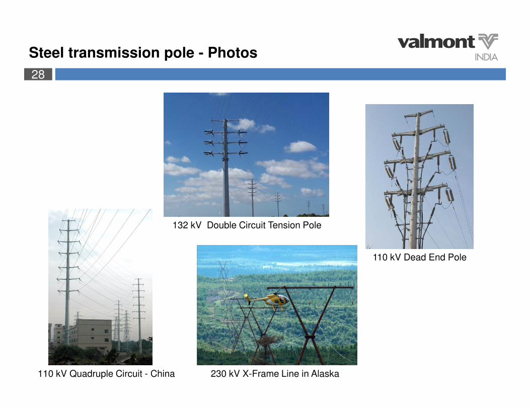
110 kV Quadruple Circuit - China 230 kV X-Frame Line in Alaska
110 kV Dead End Pole
132 kV Double Circuit Tension Pole
Steel transmission pole - Photos

29
Steel transmission pole - Photos
132 kV Guyed Tension Pole
132 kV Self Supporting Angle Pole ->
330 kV Gantry
132 kV Twin Structure

30
Steel transmission pole - Photos
230 kV Double Circuit - Manila230 kV Twin Structure - Shanghai
31
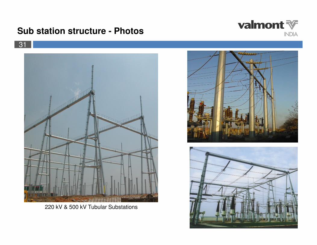
220 kV & 500 kV Tubular Substations
Sub station structure - Photos
32
Conserving Resources. Improving Life.