Valladolid, febrero 2017. - core.ac.uk · 9 Types of fans ... applications of the fans, ... pumps...
79
UNIVERSIDAD DE VALLADOLID ESCUELA DE INGENIERIAS INDUSTRIALES Grado en Ingeniería mecánica Design of a ventilation system for fan testing Autor: Fadrique Ruano, Gonzalo Responsable de Intercambio en la Uva Mª Isabel Sánchez Báscones Universidad de destino VIVES University Kortrijk (Bélgica)
Transcript of Valladolid, febrero 2017. - core.ac.uk · 9 Types of fans ... applications of the fans, ... pumps...
UNIVERSIDAD DE VALLADOLID
ESCUELA DE INGENIERIAS INDUSTRIALES
Grado en Ingeniería mecánica
Design of a ventilation system for fan testing
Autor: Fadrique Ruano, Gonzalo
Responsable de Intercambio en la Uva
Mª Isabel Sánchez Báscones
Universidad de destino
VIVES University Kortrijk (Bélgica)

Valladolid, febrero 2017.
TFG REALIZADO EN PROGRAMA DE INTERCAMBIO
TÍTULO: Design of a ventilation system for fan testing
ALUMNO: Gonzalo Fadrique
FECHA: 19 enero 2017
CENTRO: Vives University
TUTOR: Geert Furniere


Design of a ventilation system for fan testing.
2
Design of a ventilation system for fan testing.
3
Index.
1 Introduction and objectives. ........................................ 6
2 Abstract. ....................................................................... 6
3 Description of fluid machinery. ................................... 7
4 Classification of fluid machines. ................................. 8
4.1 Direction of energy exchange. .............................. 8
4.2 The degree of compressibility of the fluid. ........ 11
4.3 Operating principle. ............................................. 11
5 Balance of mechanical energy in a hydraulic machine.
.................................................................................... 12
6 Turbulence or laminar (viscous flow in tubes). ........ 14
7 Devices to measure pressure and flow. ................... 18
7.1 Pitot. ..................................................................... 18
8 Mechanical fan .......................................................... 21
9 Types of fans .............................................................. 23
9.1 Axial-flow fans ...................................................... 24
9.2 Centrifugal fan ..................................................... 26
9.3 Cross-flow fan ...................................................... 26
Design of a ventilation system for fan testing.
4
10 Uncommon types of fan. ........................................ 29
11 Noise ........................................................................ 29
12 Axial fan design. ...................................................... 30
12.1 Calculation of parameters .............................. 31
12.2 Performance characteristics .......................... 32
12.3 Causes of unstable flow. ................................. 34
12.4 Stalling effect/Stall. ........................................ 35
13 Project development. ............................................. 39
14 Calculations. ........................................................... 47
15 Conclusions. ............................................................ 50
16 Extension and further study. .................................. 52
17 Drawings. ................................................................. 54
18 Bibliography. ........................................................... 55
19 Annex. ...................................................................... 56
19.1 Practical information about PC fans. ............. 56
19.1.1 Two-wire PC Fans ..................................... 57
19.1.2 Three-wire PC Fans .................................. 59
19.1.3 Four-wire PC Fan ...................................... 61
Design of a ventilation system for fan testing.
5
19.1.4 Three wire fan to a four wire connector
header ................................................................... 65
19.2 Computational Fluid Dynamics (CFD) ............ 66
19.2.1 Process of CFD ......................................... 67
19.2.2 Solidworks FlowXpress Report ................ 68
19.3 Parts we have .................................................. 70
Design of a ventilation system for fan testing.
6
1 Introduction and objectives.
The aim of this project is to design and build a low budget
didactic stand for testing fans and ventilation systems.
It needs to be a compact and easy to transport, in the same
way, it must be safe and firm because it is going to be used
by students in the laboratory.
The project will be based on the study of the properties and
applications of the fans, as well as general theoretical
knowledges about fluid mechanics and fluid machinery.
2 Abstract.
Ventilation systems are present in many aspects of our
lives, our own houses, hospitals, cars, factories, etc.
So it is important to know how they work, the machine
needed to boost the fluid or the type of duct necessary for
it.
Therefore, this document will discuss the types of fluid
machines that exist, how we will know the energy we would
need depending on our system and our fluid, and how we
can measure certain important parameters.
Design of a ventilation system for fan testing.
7
In particular we will focus on fans, and we will try to design
a didactic system that can be used to understand these
concepts.
At the time of carrying out the project, we count with a
limited budget, so it is tried to use recycled or low cost
pieces.
To design the system we will use computer-aided design
software such as CATIA V5 and Solidworks. There will also
be some machinery available to use in the university: 3d
printer and laser cutter. For these operations we will also
use the software: Repetier Host V 1.6.2.
3 Description of fluid machinery.
A fluid machine is a system exchanging mechanical energy
with a fluid flowing through it. Fluid machines do a variety
of jobs and are applied in hydro and thermal power
stations, in aircraft as propulsive devices, in ships as
propellers, in automobiles, and earth moving machinery.
Fluid machines serve in enormous array of applications in
our daily lives, and they play an important role in modern
world.
Design of a ventilation system for fan testing.
8
4 Classification of fluid machines.
Before describing ventilation systems and fans, it is
needed situate them in the general scheme of fluid
machines.
Fluid machines can be classified depending on
-Direction of energy exchange between the machine
and the fluid.
-The degree of compressibility of the fluid.
-Operating principle.
4.1 Direction of energy exchange.
According to this criteria, there can be found either power
absorbing machines or power producing machines.
The power absorbing machines transmit energy to the
fluid. Consequently, it increases his specific energy
between inlet and outlet of the machine.
Examples of this kind of machines are pumps,
compressors and fans. Pumps and compressors increase
Design of a ventilation system for fan testing.
9
the energy of the fluid and may be positive displacement
or rotodynamic.
A pump is a turbo machine wherein the fluid is liquid and
power is given by an electric motor to raise pressure of the
fluid.
A compressor transmits power to a gas to raise pressure
but with small increase in velocity.
A fan imparts motion to gas with small change in pressure.
A fan blower increases the velocity of gas with small
pressure. Fans are always rotodynamic.
In power absorbing machines the driver is usually an
electric motor but it can be also an internal combustion
engine or a gas turbine.
The power producing machines extract energy from the
fluid. Some examples are steam, hydraulic (Pelton, Francis
or Kaplan) and gas turbines.
In hydraulic turbines the working fluid is water or oil and it
is incompressible. They can be classified in impulse and
reaction turbines. Impulse turbines are driven by one or
two high velocity jets. Each jet is accelerated in a nozzle
external to the turbine wheel known as turbine rotor.
Design of a ventilation system for fan testing.
10
In steam turbines expansion of high pressure and
temperature is expanded in fixed and moving blades of a
turbine. Steam is produced in high pressure boiler and
after expansion steam condensed in condenser.
The gas turbine is similar to a steam turbine except that air
is used instead of water as working fluid. The exhaust
gases after expansion go into the atmosphere.
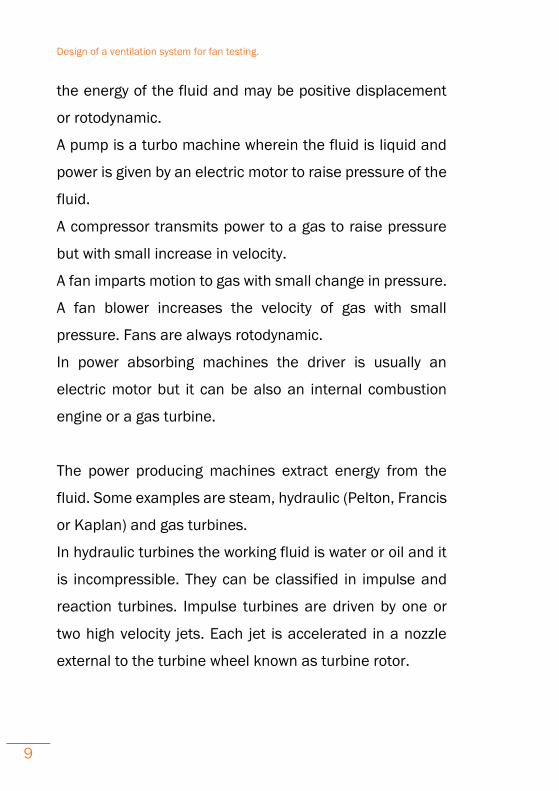
Pallet machine of positive displacement
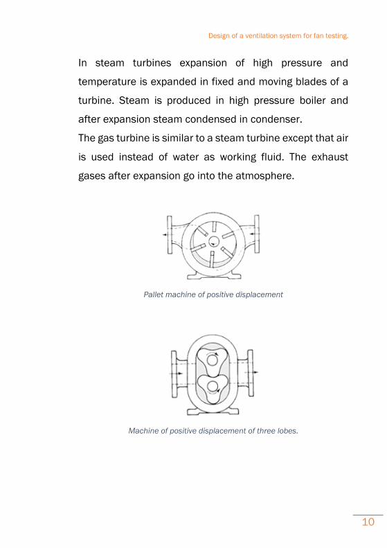
Machine of positive displacement of three lobes.
Design of a ventilation system for fan testing.
11
4.2 The degree of compressibility of the fluid.
Depending on the compressibility of the fluid that is going
through the machine, they can be classified in hydraulic
machines or heat engines (compressible flow machines).
In hydraulic machines specific volume variations
experienced by the They fluid through the machine are
negligible. This occurs when the fluid is a liquid, or when a
gas undergoes minor variations in pressure, as in the case
of the fans.
In compressible flow machines, variations of density
experimented by the fluid are not insignificant. The
mechanical and thermal decoupling of the equations is not
possible and it is necessary to establish a balance of total
energy.
4.3 Operating principle.
Fluid machines can be also classified as:
· Positive displacement machines
· Rotodynamic machines.
In positive displacement machines fluid is drawn into a
finite space bounded by mechanical parts, then sealed in
Design of a ventilation system for fan testing.
12
it, and then forced out from space and the cycle is
repeated. The flow is intermittent and depends on the
dimensions of the space (chamber). Gear pumps, vane
pumps are all positive displacement pumps.
In rotodynamic machines there is free passage between
inlet and outlet of the machine without intermittent sealing
taking place. In these machines there is a rotor which is
able to rotate continuously and freely in the fluid. The
transfer of energy is continuous resulting the change of
pressure or momentum of the fluid. Centrifugal blower,
centrifugal pumps and hydraulic turbines are some
examples of rotodynamic machines.
5 Balance of mechanical energy in a
hydraulic machine.
In order to establish the integral balance of mechanical
energy in a hydraulic machine, we will consider this as a
black box with just one input and output. From each way
we will only know the energy that it is exchanged with the
environment.
Design of a ventilation system for fan testing.
13
Hydraulic machines are incompressible flow machines so
there is a decoupling between the mechanical and thermal
equations in the general equations of fluid mechanics.
(𝑝
𝜌+
𝑣2
2+ 𝑈)
𝑜
− (𝑝
𝜌+
𝑣2
2+ 𝑈)
𝑖
=𝑊
𝐺−
∅
𝐺
Where:
(𝑝
𝜌+
𝑣2
2+ 𝑈)
𝑜𝑢𝑡𝑝𝑢𝑡/𝑖𝑛𝑝𝑢𝑡 → Specific mechanical
energy between the output and the inlet of the machine.
𝑊
𝐺 →Specific mechanical energy that is provided or
extracted in the machine shaft.
∅
𝐺 → Specific energy degraded due to viscous
dissipation.
If we apply this equation to a fan, we can obtain the
increase of energy between the inlet and outlet as follow:
∆𝑃 = (𝑃 +𝑣2
2𝜌 + 𝜌𝑔𝑧)
𝑜
− (𝑃 +𝑣2
2𝜌 + 𝜌𝑔𝑧)
𝑖
Design of a ventilation system for fan testing.
14
Unless there is a significant difference of level between the
input and the output of the fan we can suppose that (zo-zi)
≈ 0. Moreover, the air velocity upstream of the aspiration,
where the atmospheric pressure is present, is zero, so:
∆𝑃 = 𝑃𝑜 − 𝑃𝑎𝑡𝑚 +1
2𝜌𝑜𝑣𝑜
2 = ∆𝑃𝑠 + ∆𝑃𝑑
𝑆𝑡𝑎𝑡𝑖𝑐 𝑝𝑟𝑒𝑠𝑠𝑢𝑟𝑒 𝑗𝑢𝑚𝑝: ∆𝑃𝑠 = 𝑃𝑜𝑢𝑡𝑝𝑢𝑡 − 𝑃𝑎𝑡𝑚
𝐷𝑦𝑛𝑎𝑚𝑖𝑐 𝑝𝑟𝑒𝑠𝑠𝑢𝑟𝑒 𝑗𝑢𝑚𝑝: ∆𝑃𝑑 =1
2𝜌𝑜𝑣𝑜
2
6 Turbulence or laminar (viscous flow in
tubes).
An important problem when we are designing piping
systems is what type of flow we desire to have inside the
ducts. However, there are no general analysis of fluid
motion yet. We can only find some particular solutions,
some rather specific digital computer solutions, and there
are a great many experimental data.
Turbulent or laminar flow is due to a profound change in
fluid behavior occurs at moderate Reynolds numbers. We
Design of a ventilation system for fan testing.
15
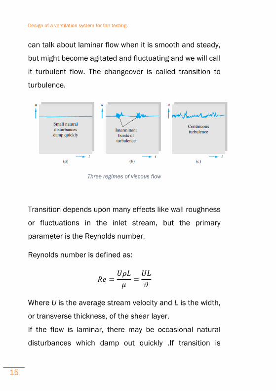
can talk about laminar flow when it is smooth and steady,
but might become agitated and fluctuating and we will call
it turbulent flow. The changeover is called transition to
turbulence.
Three regimes of viscous flow
Transition depends upon many effects like wall roughness
or fluctuations in the inlet stream, but the primary
parameter is the Reynolds number.
Reynolds number is defined as:
𝑅𝑒 =𝑈𝜌𝐿
𝜇=
𝑈𝐿
𝜗
Where U is the average stream velocity and L is the width,
or transverse thickness, of the shear layer.
If the flow is laminar, there may be occasional natural
disturbances which damp out quickly .If transition is
Design of a ventilation system for fan testing.
16
occurring, there will be sharp bursts of turbulent
fluctuation. At sufficiently large Reynolds, the flow will
fluctuate continually and is called fully turbulent.
When talking about piping systems the laminar parabolic
flow profile becomes unstable at approximately Re = 2300
and begins to form slugs or puffs of intense turbulence.
These are representative ranges which vary somewhat
with flow geometry, surface roughness, and the level of
fluctuations in the inlet stream
·0 < Re < 1: highly viscous laminar “creeping”
motion.
·1 < Re < 100: laminar, strong Reynolds-number
dependence.
·10 < Re < 103: laminar, boundary-layer theory
useful.
·103 < Re < 104: transition to turbulence.
·104 < Re < 106: turbulent, moderate Reynolds-
number dependence.
·106 < Re< ∞: turbulent, slight Reynolds-number
dependence.

Design of a ventilation system for fan testing.
17
Developing velocity profiles and pressure drop in a duct.
Design of a ventilation system for fan testing.
18
7 Devices to measure pressure and flow.
7.1 Pitot.
A pitot tube is used in wind tunnel experiments and on
airplanes to measure flow speed. It's a slender tube that
has two holes on it. The front hole is placed in the
airstream to measure what is called the stagnation
pressure. The side hole measures the static pressure. By
measuring the difference between these pressures, you
get the dynamic pressure, which can be used to calculate
airspeed.
A flow can be considered incompressible if its velocity is
less than 30% of its sonic velocity. For such a fluid, it is
possible to apply the Bernoulli equation along a streamline
and describe the relationship between pressure and
velocity. So in the case of the Pitot tube, we consider:
𝑣12
2𝑔+ 𝑧1 +
𝑃1
𝜌𝑔=
𝑣22
2𝑔+ 𝑧2 +
𝑃2
𝜌𝑔
All terms on the left side represent the stagnation point
(entrance of the pitot tube) where P1 is the stagnation
Design of a ventilation system for fan testing.
19
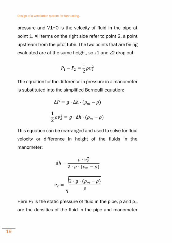
pressure and V1=0 is the velocity of fluid in the pipe at
point 1. All terms on the right side refer to point 2, a point
upstream from the pitot tube. The two points that are being
evaluated are at the same height, so z1 and z2 drop out
𝑃1 − 𝑃2 =1
2𝜌𝑣2
2
The equation for the difference in pressure in a manometer
is substituted into the simplified Bernoulli equation:
∆𝑃 = 𝑔 · ∆ℎ · (𝜌𝑚 − 𝜌)
1
2𝜌𝑣2
2 = 𝑔 · ∆ℎ · (𝜌𝑚 − 𝜌)
This equation can be rearranged and used to solve for fluid
velocity or difference in height of the fluids in the
manometer:
∆ℎ =𝜌 · 𝑣2
2
2 · 𝑔 · (𝜌𝑚 − 𝜌)
𝑣2 = √2 · 𝑔 · (𝜌𝑚 − 𝜌)
𝜌
Here P2 is the static pressure of fluid in the pipe, ρ and ρm
are the densities of the fluid in the pipe and manometer
Design of a ventilation system for fan testing.
20
fluid, g is the gravitational constant and ∆h is the
difference in height of the manometer fluid.
Pitot tube sensors, flow nozzle or Venturi tubes are
classified as flow measuring devices which utilize
differential pressure to measure volumetric flow, but to use
this devices some conditions need to be achieved.
The fluid has to completely fill the pipe so that the
measured differential pressure is representative of the
volumetric flow. Fluids in partially filled pipes can only be
measured if a full pipe can be arranged (e.g. by means of
a siphon)
The fluid must be single-phase. Two-phase fluids (e.g.
water-air mixtures) cannot be measured.
Design of a ventilation system for fan testing.
21
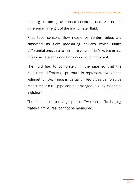
8 Mechanical fan
A fan is a machine used to create flow within a fluid,
typically a gas such as air. The fan consists of a rotating
arrangement of vanes or blades which act on the fluid. The
rotating assembly of blades and hub is known as an
impeller, a rotor, or a runner. Usually, it is contained within
some form of housing or case. This may direct the airflow
or increase safety by preventing objects from contacting
the fan blades. Most fans are powered by electric motors,
but other sources of power may be used, including
hydraulic motors and internal combustion engines.
Fans produce flows with high volume and low pressure
(although higher than ambient pressure), as opposed to
compressors which produce high pressures at a
comparatively low volume. A fan blade will often rotate
when exposed to a fluid stream, and devices that take
advantage of this, such as anemometers and wind
turbines, often have designs similar to a fan.
Typical applications include climate control and personal
thermal comfort (e.g. an electric table or floor fan), vehicle
and machinery cooling systems, ventilation, fume
Design of a ventilation system for fan testing.
22
extraction, winnowing (e.g. separating chaff of cereal
grains), removing dust (e.g. in a vacuum cleaner), drying
(usually in combination with heat) and to provide draft for
a fire. While fans are often used to cool people, they do not
actually cool air (if anything, electric fans warm it slightly
due to the warming of their motors), but work by
evaporative cooling of sweat and increased heat
convection into the surrounding air due to the airflow from
the fans. Thus, fans may become ineffective at cooling the
body if the surrounding air is near body temperature and
contains high humidity.
Design of a ventilation system for fan testing.
23
9 Types of fans
Revolving blade fans are made in a wide range of designs.
They are used on the floor, table, desk, or hung from the
ceiling. They can also be built into a window, wall, roof,
chimney, etc. Most electronic systems such as computers
include fans to cool circuits inside, and in appliances such
as hair dryers and portable space heaters and
mounted/installed wall heaters. They are also used for
moving air in air-conditioning systems, and in automotive
engines, where they are driven by belts or by direct motor.
Fans used for comfort create a wind chill by increasing the
heat transfer coefficient, but do not lower temperatures
directly. Fans used to cool electrical equipment or in
engines or other machines do cool the equipment directly
by forcing hot air into the cooler environment outside the
machine. There are three main types of fans used for
moving air, axial, centrifugal (also called radial) and cross
flow (also called tangential). The American Society of
Mechanical Engineers Performance Testing Code 11 (PTC)
provides standard procedures for conducting and
reporting tests on fans, including those of the centrifugal,
axial, and mixed flows.
Design of a ventilation system for fan testing.
24
9.1 Axial-flow fans
Axial-flow fans have blades that force air to move parallel
to the shaft about which the blades rotate. This type of fan
is used in a wide variety of applications, ranging from small
cooling fans for electronics to the giant fans used in wind
tunnels. Axial flow fans are applied in air conditioning and
industrial process applications. Standard axial flow fans
have diameters from 300–400 mm or 1800 to 2000 mm
and work under pressures up to 800 Pascal. Special types
of fans are used as low pressure compressor stages in
aircraft engines. Examples of axial fans are:
Table fan: Basic elements of a typical table fan
include the fan blade, base, armature and lead
wires, motor, blade guard, motor housing, oscillator
gearbox, and oscillator shaft. The oscillator is a
mechanism that moves the fan from side to side.
The armature shaft comes out on both ends of the
motor, one end of the shaft is attached to the blade
and the other is attached to the oscillator gearbox.
The motor case joins to the gearbox to contain the
rotor and stator. The oscillator shaft combines to
the weighted base and the gearbox. A motor
Design of a ventilation system for fan testing.
25
housing covers the oscillator mechanism. The
blade guard joins to the motor case for safety.
Ceiling fan: A fan suspended from the ceiling of a
room is a ceiling fan. Most ceiling fans rotate at
relatively low speeds and do not have blade guards.
Ceiling fans can be found in both residential and
industrial/commercial settings.
In automobiles, a mechanical fan provides engine
cooling and prevents the engine from overheating
by blowing or drawing air through a coolant-filled
radiator. The fan may be driven with a belt and
pulley off the engine's crankshaft or an electric
motor switched on or off by a thermostatic switch.
Computer cooling fan for cooling electrical
components: Variable-pitch fan: A variable-pitch fan
is used where precise control of static pressure
within supply ducts is required. The blades are
arranged to rotate upon a control-pitch hub. The fan
wheel will spin at a constant speed. As the hub
moves toward the rotor, the blades increase their
angle of attack and an increase in flow results.
Design of a ventilation system for fan testing.
26
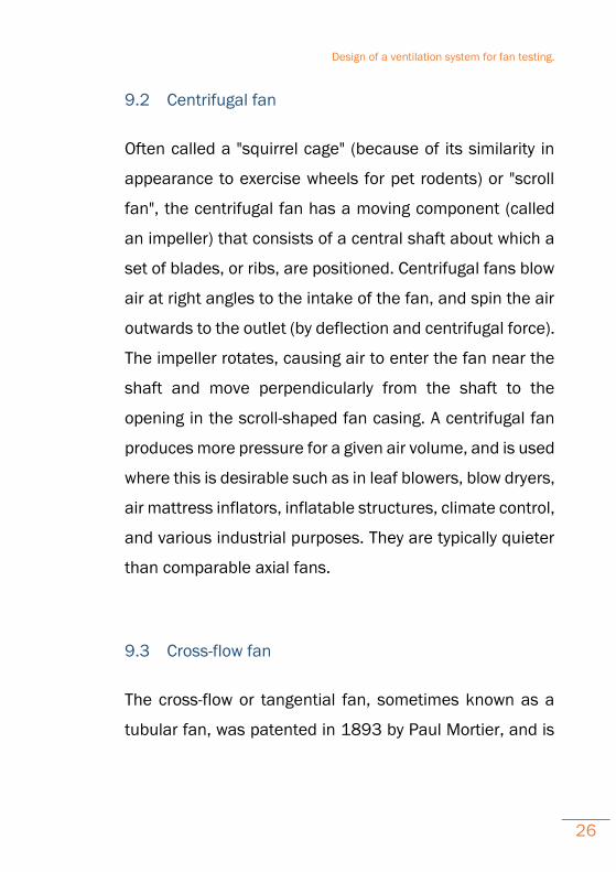
9.2 Centrifugal fan
Often called a "squirrel cage" (because of its similarity in
appearance to exercise wheels for pet rodents) or "scroll
fan", the centrifugal fan has a moving component (called
an impeller) that consists of a central shaft about which a
set of blades, or ribs, are positioned. Centrifugal fans blow
air at right angles to the intake of the fan, and spin the air
outwards to the outlet (by deflection and centrifugal force).
The impeller rotates, causing air to enter the fan near the
shaft and move perpendicularly from the shaft to the
opening in the scroll-shaped fan casing. A centrifugal fan
produces more pressure for a given air volume, and is used
where this is desirable such as in leaf blowers, blow dryers,
air mattress inflators, inflatable structures, climate control,
and various industrial purposes. They are typically quieter
than comparable axial fans.
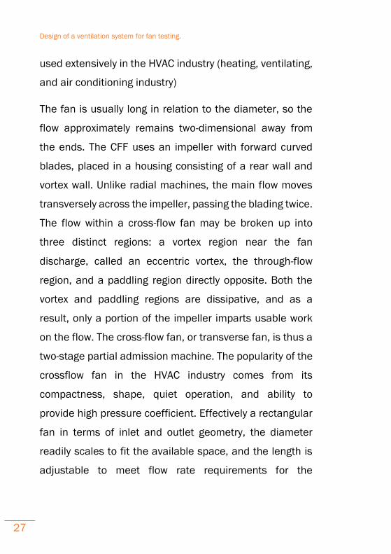
9.3 Cross-flow fan
The cross-flow or tangential fan, sometimes known as a
tubular fan, was patented in 1893 by Paul Mortier, and is
Design of a ventilation system for fan testing.
27
used extensively in the HVAC industry (heating, ventilating,
and air conditioning industry)
The fan is usually long in relation to the diameter, so the
flow approximately remains two-dimensional away from
the ends. The CFF uses an impeller with forward curved
blades, placed in a housing consisting of a rear wall and
vortex wall. Unlike radial machines, the main flow moves
transversely across the impeller, passing the blading twice.
The flow within a cross-flow fan may be broken up into
three distinct regions: a vortex region near the fan
discharge, called an eccentric vortex, the through-flow
region, and a paddling region directly opposite. Both the
vortex and paddling regions are dissipative, and as a
result, only a portion of the impeller imparts usable work
on the flow. The cross-flow fan, or transverse fan, is thus a
two-stage partial admission machine. The popularity of the
crossflow fan in the HVAC industry comes from its
compactness, shape, quiet operation, and ability to
provide high pressure coefficient. Effectively a rectangular
fan in terms of inlet and outlet geometry, the diameter
readily scales to fit the available space, and the length is
adjustable to meet flow rate requirements for the
Design of a ventilation system for fan testing.
28
particular application. Common household tower fans are
also cross-flow fans.
One phenomenon particular to the cross-flow fan is that,
as the blades rotate, the local air incidence angle changes.
The result is that in certain positions the blades act as
compressors (pressure increase), while at other azimuthal
locations the blades act as turbines (pressure decrease).
Design of a ventilation system for fan testing.
29
10 Uncommon types of fan.
There are some other kind of fans that are not widely used
but still exist and we have to mention for thoroughness
reasons. These are the following:
Bellows
Convective
Electrostatic
11 Noise
One aspect that few people consider when choosing a fan
is the noise produced by the fans operation. Fans generate
noise from the rapid flow of air around blades and
obstacles, and sometimes from the motor. Fan noise has
been found to be roughly proportional to the fifth power of
fan speed; halving speed reduces noise by about 15 dB.
Once our project ventilation system is mainly consists of
axial flow fans; further analysis on the design of those fans
should be done.
Design of a ventilation system for fan testing.
30
12 Axial fan design.
An axial fan is a type of a compressor that increases the
pressure of the air flowing through it. The blades of the
axial flow fans force air to move parallel to the shaft about
which the blades rotate. In other words, the flow is axially
in and axially out, linearly, hence their name. The design
priorities in an axial fan revolve around the design of the
propeller that creates the pressure difference and hence
the suction force that retains the flow across the fan. The
main components that need to be studied in the designing
of the propeller include the number of blades and the
design of each blade. Their applications include propellers
in aircraft, helicopters, hovercraft, ships and hydrofoils.
They are also used in wind tunnels and cooling towers. If
the propeller is exercising propulsion, then efficiency is the
only parameter of interest and other parameters like power
required and flow rate are considered of no interest. In
case the propeller is used as a fan, the parameters of
interest include power, flow rate, pressure rise and
efficiency.
Design of a ventilation system for fan testing.
31
An axial fan consists of much fewer blades i.e., two to six,
as compared to ducted fans. Axial fans operate at high
specific speed i.e., high flow rate and low head and hence
adding more blades will restrict the high flow rate required
for its operation. Due to fewer blades, they are unable to
impose their geometry on the flow, making the rotor
geometry and the inlet and outlet velocity triangles
meaningless. Also the blades are made very long with
varying blade sections along the radius.
12.1 Calculation of parameters
Since the calculation cannot be done using the inlet and
outlet velocity triangles, which is not the case in other
turbomachines, calculation is done by considering a mean
velocity triangle for flow only through an infinitesimal blade
element. The blade is divided into many small elements
and various parameters are determined separately for
each element. There are two theories that solve the
parameters for axial fans:
Slipstream Theory
Blade Element Theory
Design of a ventilation system for fan testing.
32
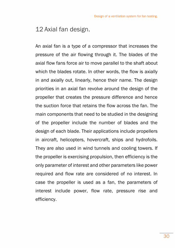
Variation of pressure and velocity of flow.
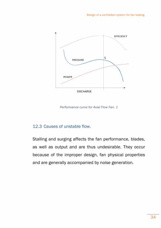
12.2 Performance characteristics
The relationship between the pressure variation and the
volume flow rate are important characteristics of fans. The
typical characteristics of axial fans can be studied from the
performance curves. The performance curve for the axial
fan is shown in the following figure. (The vertical line joining
the maximum efficiency point is drawn which meets the
Design of a ventilation system for fan testing.
33
Pressure curve at point "S"). The following can be inferred
from the curve:
As the flow rate increases from zero the efficiency
increases to a particular point reaches maximum
value and then decreases.
The power output of the fans increases with almost
constant positive slope.
The pressure fluctuations are observed at low
discharges and at flow rates (as indicated by the
point "S") the pressure deceases.
The pressure variations to the left of the point "S"
causes for unsteady flow which are due to the two
effects of Stalling and surging.
Design of a ventilation system for fan testing.
34
Performance curve for Axial Flow Fan. 1
12.3 Causes of unstable flow.
Stalling and surging affects the fan performance, blades,
as well as output and are thus undesirable. They occur
because of the improper design, fan physical properties
and are generally accompanied by noise generation.
Design of a ventilation system for fan testing.
35
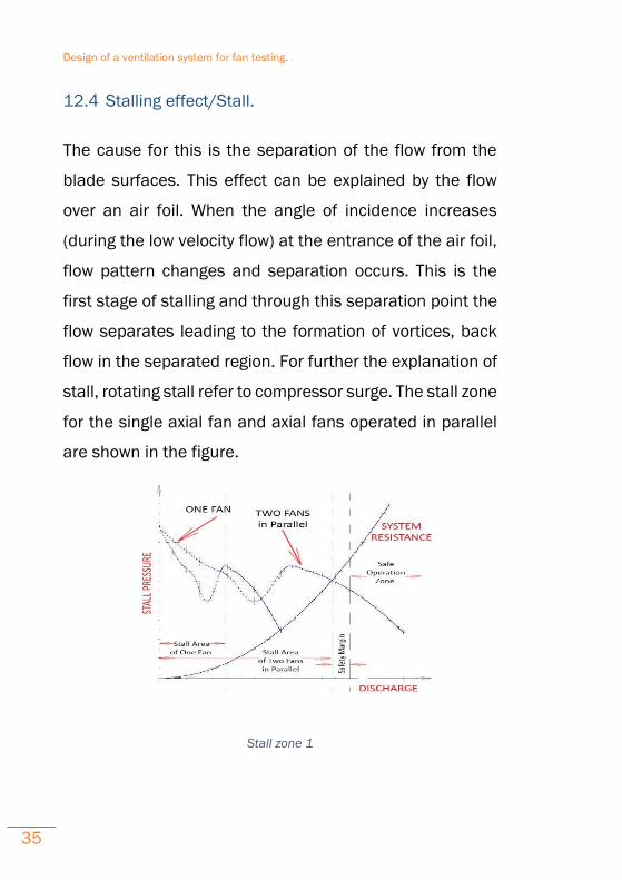
12.4 Stalling effect/Stall.
The cause for this is the separation of the flow from the
blade surfaces. This effect can be explained by the flow
over an air foil. When the angle of incidence increases
(during the low velocity flow) at the entrance of the air foil,
flow pattern changes and separation occurs. This is the
first stage of stalling and through this separation point the
flow separates leading to the formation of vortices, back
flow in the separated region. For further the explanation of
stall, rotating stall refer to compressor surge. The stall zone
for the single axial fan and axial fans operated in parallel
are shown in the figure.
Stall zone 1
Design of a ventilation system for fan testing.
36
This figure shows the Stall Prone Areas differently for one
fan and two fans in parallel.
The following can be inferred from the graph:
For the fans operated in parallel, the performance
is less when compared to the individual fans.
The fans should be operated in safe operation zone
to avoid the stalling effects.
Many Axial fan failures have happened after controlled
blade axial fans were locked in a fixed position and
Variable Frequency Drives (VFDs) were installed. The VFDs
are not practical for some Axial fans. Axial fans with severe
instability regions should not be operated at blades’
angles, rotational speeds, mass flow rates, and pressures
that expose the fan to stall conditions.
Surging effect/Surge
Surging should not be confused with stalling. Stalling
occurs only if there is insufficient air entering into the fan
blades causing separation of flow on the blade surface.
Surging or the unstable flow causing complete breakdown
Design of a ventilation system for fan testing.
37
in fans is mainly contributed by the three factors:System
surge,fan surge and paralleling.
System surge
This situation occurs when the system resistance curve
and static pressure curve of the fan intersect have similar
slope or parallel to each other. Rather than intersecting at
a definite point the curves intersect over certain region
reporting system surge. These characteristics are not
observed in axial fans.
Fan surge.
This unstable operation results from the development of
pressure gradients in the opposite direction of the flow.
Maximum pressure is observed at the discharge of the
impeller blade and minimum pressure on the side opposite
to the discharge side. When the impeller blades are not
rotating these adverse pressure gradients pump the flow
in the direction opposite to the direction of the fan. The
result is the oscillation of the fan blades creating vibrations
and hence noise.
Paralleling.
Design of a ventilation system for fan testing.
38
This effect is seen only in case of multiple fans. The air flow
capacities of the fans are compared and connected in
same outlet or same inlet conditions. This causes noise,
specifically referred to as Beating in case of fans in
parallel. To avoid beating use is made of differing inlet
conditions, differences in rotational speeds of the fans,
etc.
Methods to avoid unsteady flow.
By designing the fan blades with proper hub-to-tip ratio and
analyzing performance on the number of blades so that the
flow doesn't separate on the blade surface these effects
can be reduced. Some of the methods to overcome these
effects are re-circulation of excess air through the fan, axial
fans are high specific speed devices operating them at
high efficiency and to minimize the effects they have to be
operated at low speeds. For controlling and directing the
flow use of guide vanes is suggested. Turbulent flows at
the inlet and outlet of the fans cause stalling so the flow
should be made laminar to prevent the effect.
Design of a ventilation system for fan testing.
39
13 Project development.
In this section we will discuss about all the ideas we had
during the development of this project, with the final aim
to select the better one and put it into practice.
First designs.
As it is said in the introduction of this document, the aim of
this project is to make an easy and didactic stand to test
fans. The idea is to create ducts through which the air will
be driven by the fans. It is intended to develop a system in
which fans can be tested in series and in parallel.
The machines we are supposed to use are two 3D printers
and a laser cutter, besides basic tools as screwdrivers,
bolts etc.
Several alternative designs are presented and evaluated
according to the given criteria, and then the better design
selected.
Thus, the first idea was to create a piping system with PVC
tubes. However, this design was turned down because it is
not easy and quick to assemble and dissemble if you want
to change the layout. Furthermore it would be necessary to
Design of a ventilation system for fan testing.
40
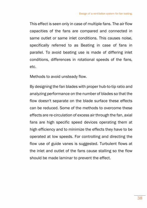
construct a support structure to fix the pipes. This layout is
called as ‘Piping design’ when comparing.
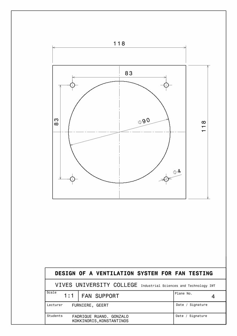
A simple piece was designed to fix the fan between the
pipes:
It contains four holes in the front side to fix the fan and two
more in the bottom to be attached on the bench.
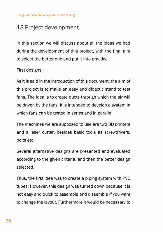
We would also need several pieces to support all the pipes.
As shown in the next picture, it is a simple base that
properly distributed would hold up all the system.
Design of a ventilation system for fan testing.
41
Support
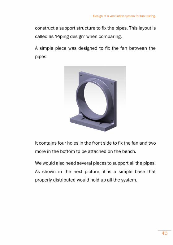
Modular design.
After this first design, a modular layout was thought. It
consists of cubes of 110 mm side with male and female
connections. This will be called ‘Modular design A’ in order
to compare with the other ideas.
90 degrees module

Design of a ventilation system for fan testing.
42
This design contains straight, corner (90 degrees), ‘T’
connections and another box more with a cover to insert
the fans.
Straight module
The problem in this case was that it was difficult to print
because the 3D printer would have needed a lot of support
material to build the layers. It also would have increased
the printing time and the cost of the system due to the big
amount of material needed.
Design of a ventilation system for fan testing.
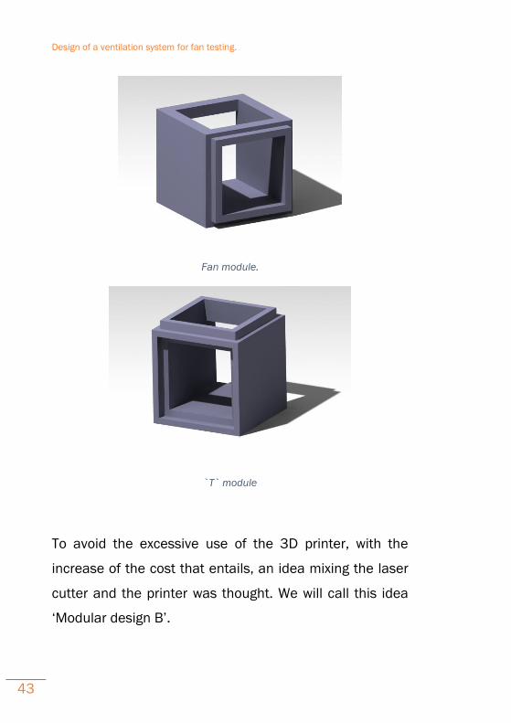
43
Fan module.
`T` module
To avoid the excessive use of the 3D printer, with the
increase of the cost that entails, an idea mixing the laser
cutter and the printer was thought. We will call this idea
‘Modular design B’.

Design of a ventilation system for fan testing.
44
It consists in creating the less pieces possible to build the
system just combining them.
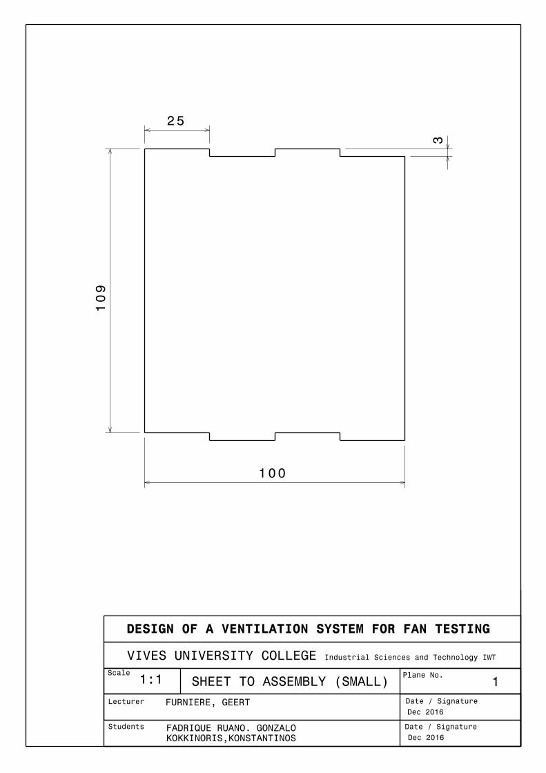
The main piece is the interface showed in the following
picture:
Interface
It is designed to connect the tubes regardless of whether it
is straight, elbow or ‘T’. With two of these interfaces you
can make a straight tube or a ‘T’ leaving one side open;
with two interfaces and a cover you can make a corner.
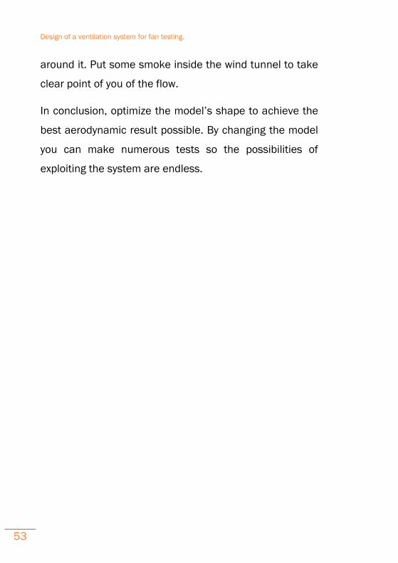
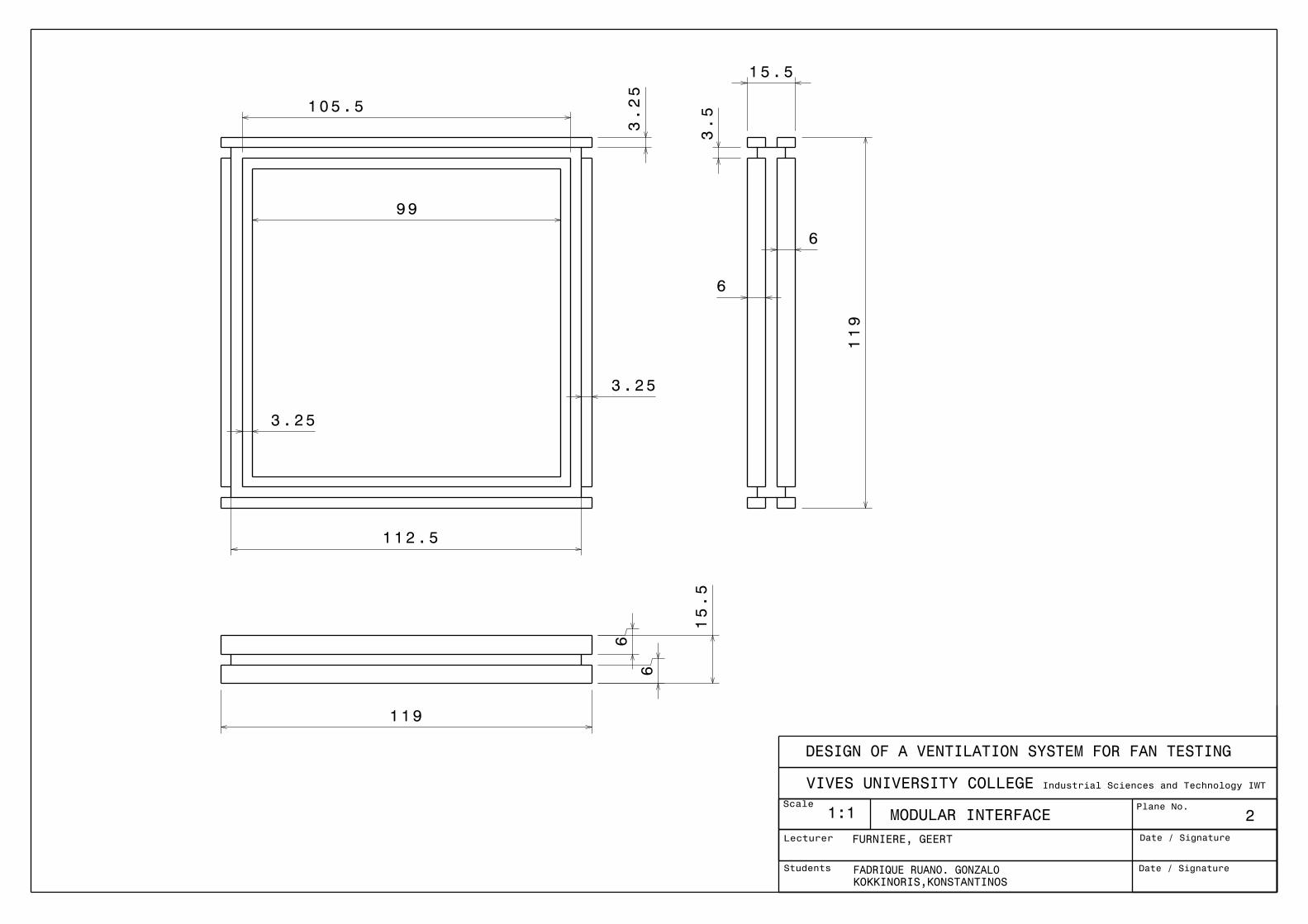
To make the connectors between the interfaces, we are
going to create a square pipe with four PVC sheets that will
join together.
Design of a ventilation system for fan testing.
45
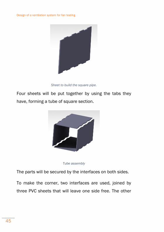
Sheet to build the square pipe.
Four sheets will be put together by using the tabs they
have, forming a tube of square section.
Tube assembly
The parts will be secured by the interfaces on both sides.
To make the corner, two interfaces are used, joined by
three PVC sheets that will leave one side free. The other
Design of a ventilation system for fan testing.
46
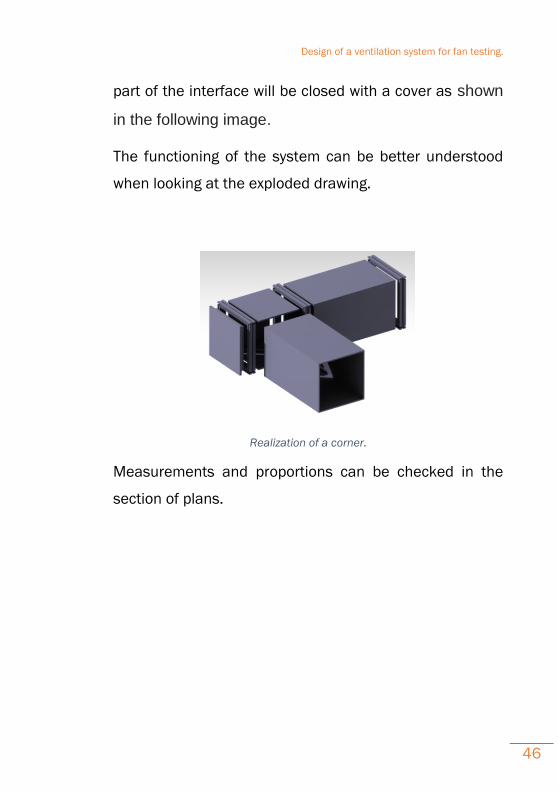
part of the interface will be closed with a cover as shown
in the following image.
The functioning of the system can be better understood
when looking at the exploded drawing.
Realization of a corner.
Measurements and proportions can be checked in the
section of plans.

Design of a ventilation system for fan testing.
47
14 Calculations.
In this section it is going to be calculated an estimated cost
of printing one piece of each idea, to see which one would
be the most suitable to make the project the cheapest way,
not only in money but also in time.
The material used by the 3D printer is a plastic usually
called PLA (polylactic acid). An approximately density for
this material is 1,25 g/cm3 . So the method to calculate
the cost of printing is based on calculate the mass of
material needed for each piece. Knowing the volume (it
can be obtained from the CAD software used to make the
3D models) and the density of the material the mass is
easy to calculate.
However, we have to make some approximations
concerning this method, because the pieces we print are
no totally full of material. This is due to the 3D printer,
which puts layers forming 90 degrees, so it leaves some
holes between the lines. But, as all the pieces are made
with same printer, all the pieces will have the same spaces.
Having this note in mind, the real density of the pieces
would be lower than the one we will calculate with the
Design of a ventilation system for fan testing.
48
theoretical density of the plastic. In our case, we are just
going to compare them, so it will not suppose a mistake,
although we have to keep in mind that the numbers we will
obtain are not totally exact.
For the piping design, several supports would be necessary
to fix the pipes on the ground. In this case the volume
would be 0,000168 m3.
In the second idea, that we have called ‘Modular design A’
the volume would be 0,000627 m3.
And the design with the interface, called ‘Modular design
B’ the volume would be 0,000052 m3.
At this point a clarification should be done regarding the
number of pieces of each type.
In the first (piping design) and the third (Mod. Design B)
ideas the number of pieces are going to be similar because
they will be the support parts of the system. However, in
the modular design with only cubes (Mod. Design A) there
would be many more pieces that need to be printed
because in this layout the cubes themselves are the
support of the system. So this design could be turned down
without any calculations.
Design of a ventilation system for fan testing.
49
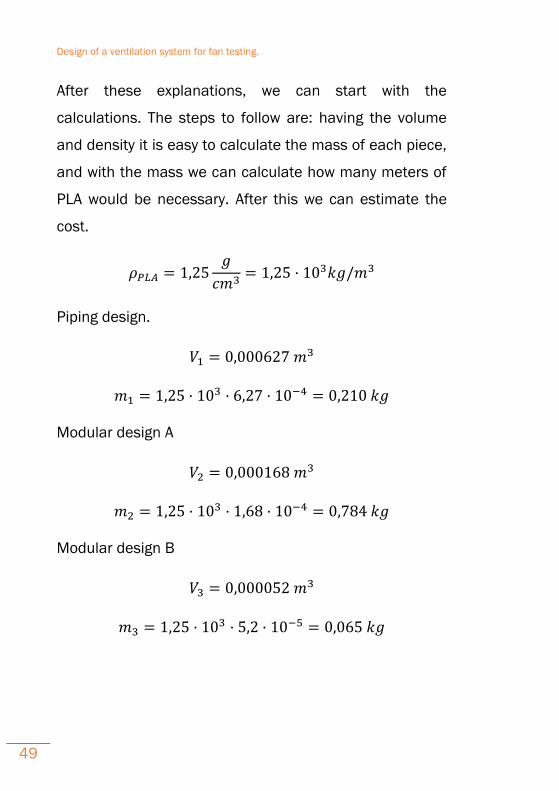
After these explanations, we can start with the
calculations. The steps to follow are: having the volume
and density it is easy to calculate the mass of each piece,
and with the mass we can calculate how many meters of
PLA would be necessary. After this we can estimate the
cost.
𝜌𝑃𝐿𝐴 = 1,25𝑔
𝑐𝑚3= 1,25 · 103𝑘𝑔/𝑚3
Piping design.
𝑉1 = 0,000627 𝑚3
𝑚1 = 1,25 · 103 · 6,27 · 10−4 = 0,210 𝑘𝑔
Modular design A
𝑉2 = 0,000168 𝑚3
𝑚2 = 1,25 · 103 · 1,68 · 10−4 = 0,784 𝑘𝑔
Modular design B
𝑉3 = 0,000052 𝑚3
𝑚3 = 1,25 · 103 · 5,2 · 10−5 = 0,065 𝑘𝑔
Design of a ventilation system for fan testing.
50
15 Conclusions.
After the for and against arguments said about the designs
presented in the previous sections we can add some more
assessments and obtain certain conclusions.
If we discuss about the ease of use and the system
functionality the best option might be the PVC piping
system because the connections between tubes are the
stronger which means the losses are almost null.
Nevertheless, buying each PVC pipe would increase the
budget and the assembly and disassembly capacity in this
case is low because to change the layout of the system you
might use specific tools.
So, concerning the ease of assembly and disassembly the
best options are the modular designs, in which you can
change the system only using your hands.
In the section ‘calculations’ we have made an estimation
about the mass needed to print a piece in the 3D printer.
The cost of printing will be proportional to the mass, or in
the same words, the meters of PLA filament.
Another point to keep in mind is the printing time for each
piece. This time will be calculated by the software that
Design of a ventilation system for fan testing.
51
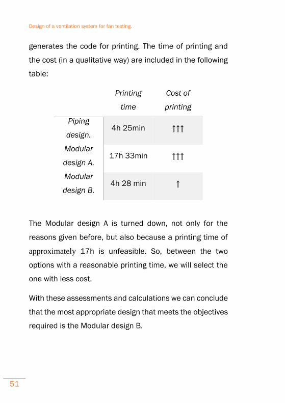
generates the code for printing. The time of printing and
the cost (in a qualitative way) are included in the following
table:
Printing
time
Cost of
printing
Piping
design. 4h 25min ↑↑↑
Modular
design A. 17h 33min ↑↑↑
Modular
design B. 4h 28 min ↑
The Modular design A is turned down, not only for the
reasons given before, but also because a printing time of
approximately 17h is unfeasible. So, between the two
options with a reasonable printing time, we will select the
one with less cost.
With these assessments and calculations we can conclude
that the most appropriate design that meets the objectives
required is the Modular design B.
Design of a ventilation system for fan testing.
52
16 Extension and further study.
Further studies could be made in this project. Of course
several factors should be taken into consideration.
First and foremost, the concept of this project was to
construct it with a low budget, so the idea of using parts
out of old computers was ingenious. The more difficult the
modifications that could be made are, the higher the cost
would be. One easy way to modify the system is by adding
some filters, valves, heaters or coolers etc, and taking as
much data as it is possible. In addition a smoke creator
device can be placed in order to visualize the flow.
One of the first idea was to create a system in which you
can test fans whether in series or in parallel. This design
could be accomplished in an easy way with the right
materials.
A step further, is to scale up the system and try to simulate
a wind tunnel. The bigger the tunnel, the greater the results
would be!
Furthermore, a real model such as a car or a wing could be
placed, and it would be a good experience to study the flow
Design of a ventilation system for fan testing.
53
around it. Put some smoke inside the wind tunnel to take
clear point of you of the flow.
In conclusion, optimize the model’s shape to achieve the
best aerodynamic result possible. By changing the model
you can make numerous tests so the possibilities of
exploiting the system are endless.

Design of a ventilation system for fan testing.
54
17 Drawings.
DESIGN OF A VENTILATION SYSTEM FOR FAN TESTING
VIVES UNIVERSITY COLLEGE Industrial Sciences and Technology IWT
Scale
Date / SignatureStudents FADRIQUE RUANO. GONZALOKOKKINORIS,KONSTANTINOS
Plane No.
Date / SignatureLecturer FURNIERE, GEERT
1:1 1SHEET TO ASSEMBLY (SMALL)
Dec 2016
Dec 2016
109
2 5
100
3
DESIGN OF A VENTILATION SYSTEM FOR FAN TESTING
VIVES UNIVERSITY COLLEGE Industrial Sciences and Technology IWTScale
Date / SignatureStudents FADRIQUE RUANO. GONZALOKOKKINORIS,KONSTANTINOS
Plane No.
Date / SignatureLecturer FURNIERE, GEERT
1:1 MODULAR INTERFACE 2
99
105.5
3.25
1 12.5
3.25
3.25
6
6
11915.5
119
3.5
1 5.5
6
6
DESIGN OF A VENTILATION SYSTEM FOR FAN TESTING
VIVES UNIVERSITY COLLEGE Industrial Sciences and Technology IWT
Scale
Date / SignatureStudents FADRIQUE RUANO. GONZALOKOKKINORIS,KONSTANTINOS
Plane No.
Date / SignatureLecturer FURNIERE, GEERT
SHEET TO ASSEMBLY1:1 3
109
200
25
DESIGN OF A VENTILATION SYSTEM FOR FAN TESTING
VIVES UNIVERSITY COLLEGE Industrial Sciences and Technology IWT
Scale
Date / SignatureStudents FADRIQUE RUANO. GONZALOKOKKINORIS,KONSTANTINOS
Plane No.
Date / SignatureLecturer FURNIERE, GEERT
1:1 FAN SUPPORT 4
118
11890
83
83
4
DESIGN OF A VENTILATION SYSTEM FOR FAN TESTING
VIVES UNIVERSITY COLLEGE Industrial Sciences and Technology IWT
Scale
Date / SignatureStudents FADRIQUE RUANO. GONZALOKOKKINORIS,KONSTANTINOS
Plane No.
Date / SignatureLecturer FURNIERE, GEERT
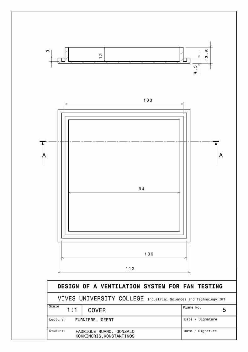
1:1 COVER 5
100
94
106
112
A A
12
3
4.5
13.5

Design of a ventilation system for fan testing.
55
18 Bibliography.
· Basic fluid mechanics and hydraulic machines, Zoeb
Husain and others.
· Turbomáquinas hidraúlicas, Claudio Mataix
· Fluid mechanics, Frank M. White
· Fundamentals of Compressible fluid Mechanics, Genick
Bar-Meir
· A text book of fluid mechanics and hydraulic machines,
Dr.R.K.Bansal.
· Competition Car Aerodynamics, Simon McBeath 2006
Haynes Publishing ISBN 978 1 84425 230 5
· http://www.cwc-group.com/5409d.html
· https://en.wikipedia.org/wiki/Mechanical_fan
· https://en.wikipedia.org/wiki/Axial_fan_design
·http://www.pcbheaven.com/wikipages/How_PC_Fans_W
ork/
·http://www.intel.com/content/www/us/en/support/boar
ds-and-kits/desktop-boards/000005560.html
Design of a ventilation system for fan testing.
56
19 Annex.
19.1 Practical information about PC fans.
Once all our fans come from old PCs we have to mention
some of their characteristics and how they improve the
performance of any computer.
The vast majority of PCs has at least one of them. They
carry the heavy load to keep the PC’s temperature cool and
functional, either by providing fresh air in the box, or by
forcing the hot air to leave a hot surface by pushing cool
air. It is more than obvious that a PC fan is not rotated from
a simple DC motor. It has the permanent magnets fixed on
the rotor, the stator carrying the coils, no brushes exist and
it has a controller; it is of course a brushless motor. (More
information about brushless motors are given later).
As long as the motor is concerned, all PC fans use
brushless motors. There are several reasons that a
brushless motor should be used, among them is the
reliability, the power efficiency and the rpm feedback. So
the motor type would not be the proper way to categorize
PC fans. Instead, to make things easier to remember the
Design of a ventilation system for fan testing.
57
categorization will be done with the most obvious
characteristic: their connector.
There are actually three different types of PC fans:
· those with a 2-pin connector
· those with a 3-pin connector
· those with a 4-pin connector
19.1.1 Two-wire PC Fans
These are the oldest and most simple PC fans. Only two
wires come out of the fan controller, the positive and the
negative. Giving power to the fan, it will rotate at full speed.
The internal diagram of a typical two-wire fan is the
following:
Design of a ventilation system for fan testing.
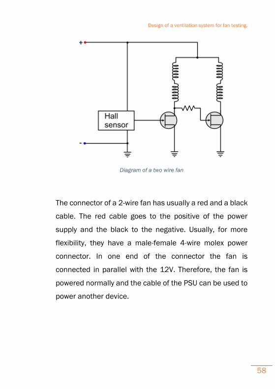
58
Diagram of a two wire fan
The connector of a 2-wire fan has usually a red and a black
cable. The red cable goes to the positive of the power
supply and the black to the negative. Usually, for more
flexibility, they have a male-female 4-wire molex power
connector. In one end of the connector the fan is
connected in parallel with the 12V. Therefore, the fan is
powered normally and the cable of the PSU can be used to
power another device.
Design of a ventilation system for fan testing.
59
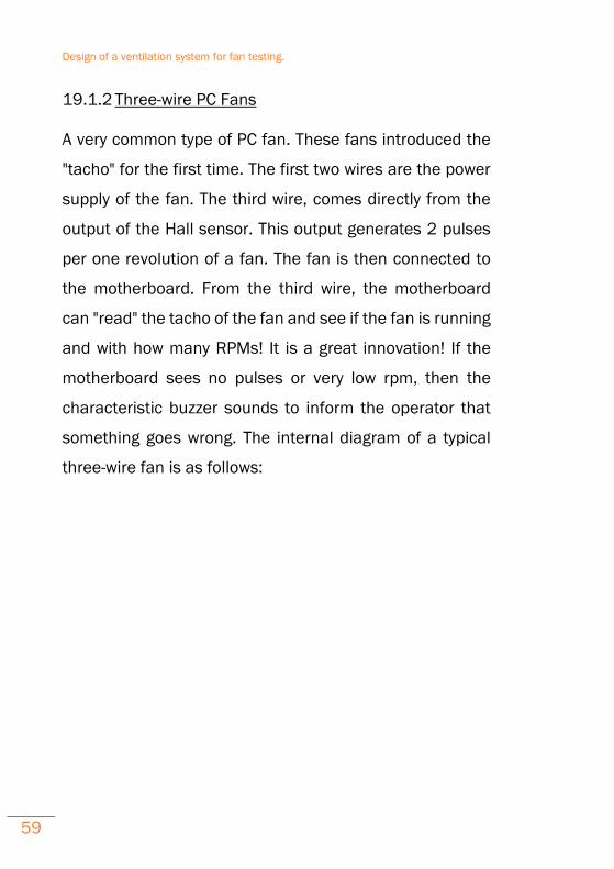
19.1.2 Three-wire PC Fans
A very common type of PC fan. These fans introduced the
"tacho" for the first time. The first two wires are the power
supply of the fan. The third wire, comes directly from the
output of the Hall sensor. This output generates 2 pulses
per one revolution of a fan. The fan is then connected to
the motherboard. From the third wire, the motherboard
can "read" the tacho of the fan and see if the fan is running
and with how many RPMs! It is a great innovation! If the
motherboard sees no pulses or very low rpm, then the
characteristic buzzer sounds to inform the operator that
something goes wrong. The internal diagram of a typical
three-wire fan is as follows:
Design of a ventilation system for fan testing.
60
Diagram of a three wire fan
It is very common that, the manufacturers do not have the
same wire provider, or their wire providers do not have the
same colored-plastic provider... Two fans with 3-wire
connectors may not have the same wire colors. Thus,
instead of using the colors to distinguish the function,
better go with the connector that is standard. No matter
what color the cable is, it will be plugged in the same
motherboard connector!
Design of a ventilation system for fan testing.
61
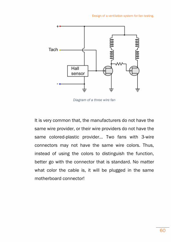
BLACK:Negative RED:Positive YELLOW:Tacho
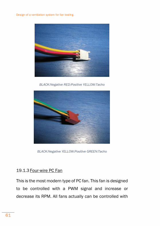
BLACK:Negative YELLOW:Positive GREEN:Tacho
19.1.3 Four-wire PC Fan
This is the most modern type of PC fan. This fan is designed
to be controlled with a PWM signal and increase or
decrease its RPM. All fans actually can be controlled with
Design of a ventilation system for fan testing.
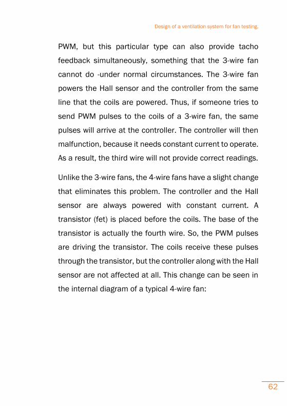
62
PWM, but this particular type can also provide tacho
feedback simultaneously, something that the 3-wire fan
cannot do -under normal circumstances. The 3-wire fan
powers the Hall sensor and the controller from the same
line that the coils are powered. Thus, if someone tries to
send PWM pulses to the coils of a 3-wire fan, the same
pulses will arrive at the controller. The controller will then
malfunction, because it needs constant current to operate.
As a result, the third wire will not provide correct readings.
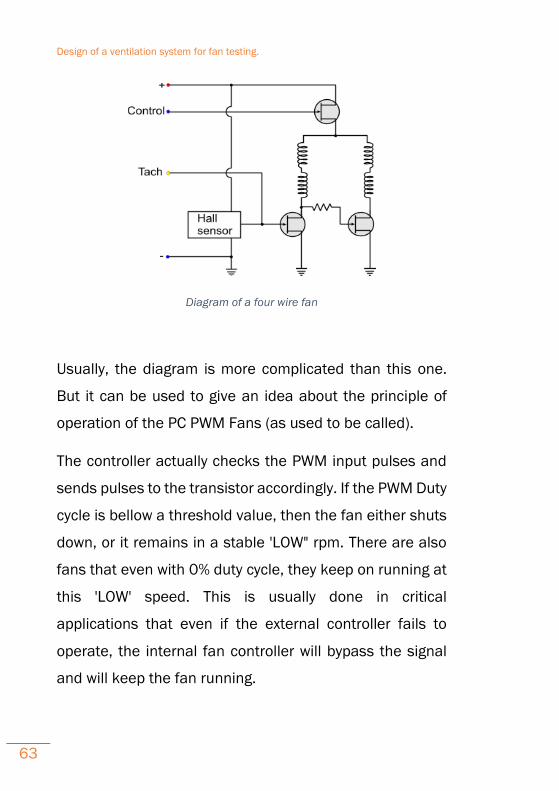
Unlike the 3-wire fans, the 4-wire fans have a slight change
that eliminates this problem. The controller and the Hall
sensor are always powered with constant current. A
transistor (fet) is placed before the coils. The base of the
transistor is actually the fourth wire. So, the PWM pulses
are driving the transistor. The coils receive these pulses
through the transistor, but the controller along with the Hall
sensor are not affected at all. This change can be seen in
the internal diagram of a typical 4-wire fan:
Design of a ventilation system for fan testing.
63
Diagram of a four wire fan
Usually, the diagram is more complicated than this one.
But it can be used to give an idea about the principle of
operation of the PC PWM Fans (as used to be called).
The controller actually checks the PWM input pulses and
sends pulses to the transistor accordingly. If the PWM Duty
cycle is bellow a threshold value, then the fan either shuts
down, or it remains in a stable 'LOW" rpm. There are also
fans that even with 0% duty cycle, they keep on running at
this 'LOW' speed. This is usually done in critical
applications that even if the external controller fails to
operate, the internal fan controller will bypass the signal
and will keep the fan running.

Design of a ventilation system for fan testing.
64
BLACK:Negative RED:Positive YELLOW:Tacho BLUE:PMW
BLACK:Negative YELLOW:Positive GREEN:Tacho BLUE:PMW
Design of a ventilation system for fan testing.
65
19.1.4 Three wire fan to a four wire connector header
Based on Intel’s website article ID: 000005560 and last
reviewed: 11-Mar-2016 ‘Chassis and processor fans use
either a three-wire or four-wire connector. The three-wire
connectors are for small chassis fans with lower power
consumption. The four-wire connectors are for processor
fans with higher power consumption.’
Strange as it may seem it is possible to connect a three
wire fan to a four wire connector! The first three pin outs of
the fans are the same for the 3 and 4 wire fans. Also, the
keys are the same for both connectors. The 4-wire
connector has smaller back-key to accept the smaller 3-
wire fan connector keys. The fan will always run at full
speed (as the control pin will not be used), but the rpm
feedback (tacho) of the fan will operate normally and the
motherboard will read the rpm normally.
Conversely, a 4-wire fan can be connected to 3-wire
connector to a 3-wire connector! The connector is larger
but the keys of the 4-wire fan have still the same distance
as the 3-wire connector. The fan will operate at full speed
all the time, as the 4th wire from the PWM control will be
on air. The motherboard will normally read the rpm
Design of a ventilation system for fan testing.
66
feedback from the fan tacho. This means that the PWM
control line must have an internal pull-up resistor, so that
when the pin is unconnected, the control FET will be kept
always ON.
19.2 Computational Fluid Dynamics (CFD)
Computational Fluid Dynamics or abbreviated CFD is a
technique that has only really been around the 1970s
because that was the time that computer’s performance
needed became available. As the title implies, CFD is a
technique that uses computers to provide simulations of
fluid flow problems. It is analysis of systems involving fluid
flow, heat transfer and associated processes (chemical
reactions) through the use of computer-based simulations.
Although the results taken are very pretty and insightful the
mathematics that goes on in the background is highly
complex. In any specific case the user has to insert the
same unknowns to run the study; which are:
· Fluid velocity in the three directions indicated as x,
y and z.
· Pressure.
Design of a ventilation system for fan testing.
67
· Density.
· Temperature.
Theoretically speaking, any fluid dynamic problem can be
solved using the equations of the underlying basic
principles:
· The principle of Conservation of Mass.
··The principle of Conservation of Momentum.
· The principle of Conservation of Energy.
However, obtaining exact solutions in more complex
studies is not possible and only certain types of ‘ideal’ flow
can be accurately predicted.
19.2.1 Process of CFD
There are five steps that need to be accomplished in order
to obtain the requesting data. First a CAD (computer aided
design) model should be made that will represent the
system that we want to study. This model can be in 2D if
2D CFD or 3D if maximum realism is required. By this way
an electronic digital model is generated .Then it is imported
into a “preprocessing” package in which the relevant
conditions are set up.
Design of a ventilation system for fan testing.
68
Afterwards, a procedure called “meshing’ is performed.
Meshing is the generation of a three dimensional grid
defining possibly millions of “cells” in which calculations
are carried out. The “solver” then performs the CFD
calculations on the meshed model. During this process the
information related with each cell is correlated to each
other and the forces and mass flow is balanced across the
whole flow “domain”, until a solution is reached.
”Post-processing” is the last step in which analysis of
various results such as pressures and velocities on and off
the surfaces of the body being tested. In this point it should
be stated that in the “meshing” procedure hexahedral (six-
sided cells) are the most common cells and are mainly
used in not complexed surfaces. As a result, they give the
most accurate mesh type.
Of course, numerous complex shapes can be created to
define an unusual surface. Such a shape is tetrahedrals
having four triangular shaped sides which in turn create
more numerical diffusion and hence errors.
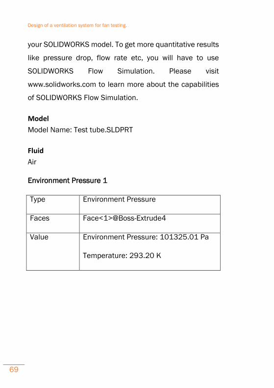
19.2.2 Solidworks FlowXpress Report
SOLIDWORKS FloXpress is a first pass qualitative flow
analysis tool which gives insight into water or air flow inside
Design of a ventilation system for fan testing.
69
your SOLIDWORKS model. To get more quantitative results
like pressure drop, flow rate etc, you will have to use
SOLIDWORKS Flow Simulation. Please visit
www.solidworks.com to learn more about the capabilities
of SOLIDWORKS Flow Simulation.
Model
Model Name: Test tube.SLDPRT
Fluid
Air
Environment Pressure 1
Type Environment Pressure
Faces Face<1>@Boss-Extrude4
Value Environment Pressure: 101325.01 Pa
Temperature: 293.20 K
Design of a ventilation system for fan testing.
70
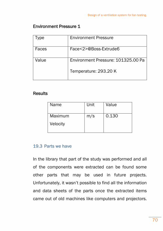
Environment Pressure 1
Type Environment Pressure
Faces Face<2>@Boss-Extrude6
Value Environment Pressure: 101325.00 Pa
Temperature: 293.20 K
Results
Name Unit Value
Maximum
Velocity
m/s 0.130
19.3 Parts we have
In the library that part of the study was performed and all
of the components were extracted can be found some
other parts that may be used in future projects.
Unfortunately, it wasn’t possible to find all the information
and data sheets of the parts once the extracted items
came out of old machines like computers and projectors.
Design of a ventilation system for fan testing.
71
Here you can find the exact nomenclature of each part we
had in our possession and some information about them.
It is obvious that each part characteristic can be correlated
with another newer if precise study would be done.The
extracted components are the following:
1)Intel C91968-002 N 5401D I1 F09A-12B3S1
01AC1H2 DC12V 0.42A NIDEC CORP.
Note: Found in datasheets: Intel C91968-003 Socket-
775 Aluminum Cooler, Nidec P/N: F09A-12B3S1
2)Intel C91968-003 Socket-775 Aluminum Cooler, Nidec
P/N: F09A-12B3S1 Intel C91968-003 (C91968003)
3)Nidec N 5409D and P/N: F09A-12B3S1 01AC1H2
DC 12V 0.42A 4-Pin / 4-Wire Connector
4)AVC FAN
Note: Information for this fan can be found in the pdf from
the link:
Design of a ventilation system for fan testing.
72
http://www.avc-
europe.eu/cms/upload/pdf/Fan_Catalo
gue.pdf
3)DC BRUSHLESS D12SL-12 DC12V 0.30A
YATELOONELECTRONICS
Note: There are no datasheets for this fan so further study
should be made to figure out their characteristics which is
out of the borders of this project.
Further datasheets can be obtained from the following link:
http://category.alldatasheet.com/index.
jsp?sSearchword=AVC%20FAN%20&sP
age=10


![First Revision No. 147-NFPA 20-2013 [ Global Input ] · PDF fileANSI/HI 1.1-1.2, Rotodynamic (Centrifugal) Pumps for Nomenclature and Definitions, 2008. ANSI/HI 1.3, Rotodynamic (Centrifugal)](https://static.fdocuments.us/doc/165x107/5a7666977f8b9a9c548d4179/first-revision-no-147-nfpa-20-2013-global-input-a-ansihi-11-12-rotodynamic.jpg)