Validator and Control Board Update Instructions for BC1 Board Update for BC1.pdf · Validator and...
12
Validator and Control Board Update Instructions for BC1 Installation Overview The update kit for the Rowe BC1 enables the changer to interface with a Mars AE/VN 120-volt validator. The validator determines the bill denominations accepted. The control board, OBA system and power supply are replaced. The instructions assume the changer has an empty lamp on the front door. If you have an early model that does not have a lamp, the related steps in the instructions can be skipped. A new lamp can easily be added if needed by drilling a new hole in the front door. The final section of these instructions contains more details. The instructions assume a new 120v Mars AE/VN series validator is being installed. The installation information is intended for experienced personnel familiar with the operation of these components. All of the installation procedures must be reviewed and understood prior to installing the kit. The installation instructions are based upon a machine that has not been modified from the original factory configuration. If the machine has been altered in any way, restore the machine to the original factory configuration prior to beginning the conversion. Kit Revisions This kit has been updated. The control board used with this kit is now similar to the BC100 and SBC2 kits. This kit can interface with validators other than the Mars AE/VN series (Coinco, Ardac, Mars VFM, etc.) but requires three additional components be soldered to the board and a different wiring harness. Contact us for details at (800) 814-7756. Kit Components The kit contains the following parts: New control board assembly yellow silk screening (part #KITBDAC1HOPPER) Jumper harness attached to Conn. 3 Validator harness attached to Conn 4 Mars; Conn. 5 for universal harnesess Validator mounting bezel (part # KITVMB) Validator template (part #PL013) Meter to register total bills inserted (part #MCVMETER-12VDC) Four self-threading Phillips screws 8-32 ½” Installation Instructions titled Validator and Control Board Update Instructions for BC1 Tools Required 1/4”, 11/32”, and 3/8” long handle nut drivers ¼” short handle nut driver Philips screwdriver Pliers Electric drill, 9/64” and 11/64” drill bit, and safety goggles Electric jigsaw with metal cutting blades Pencil to pointed metal tool (used to scratch paint) Metal file 1
Transcript of Validator and Control Board Update Instructions for BC1 Board Update for BC1.pdf · Validator and...

Validator and Control Board Update Instructions for BC1
Installation Overview The update kit for the Rowe BC1 enables the changer to interface with a Mars AE/VN 120-volt validator. The validator determines the bill denominations accepted. The control board, OBA system and power supply are replaced. The instructions assume the changer has an empty lamp on the front door. If you have an early model that does not have a lamp, the related steps in the instructions can be skipped. A new lamp can easily be added if needed by drilling a new hole in the front door. The final section of these instructions contains more details. The instructions assume a new 120v Mars AE/VN series validator is being installed. The installation information is intended for experienced personnel familiar with the operation of these components. All of the installation procedures must be reviewed and understood prior to installing the kit. The installation instructions are based upon a machine that has not been modified from the original factory configuration. If the machine has been altered in any way, restore the machine to the original factory configuration prior to beginning the conversion.
Kit Revisions This kit has been updated. The control board used with this kit is now similar to the BC100 and SBC2 kits. This kit can interface with validators other than the Mars AE/VN series (Coinco, Ardac, Mars VFM, etc.) but requires three additional components be soldered to the board and a different wiring harness. Contact us for details at (800) 814-7756.
Kit Components The kit contains the following parts: New control board assembly yellow silk screening (part #KITBDAC1HOPPER) Jumper harness attached to Conn. 3 Validator harness attached to Conn 4 Mars; Conn. 5 for universal harnesess Validator mounting bezel (part # KITVMB) Validator template (part #PL013) Meter to register total bills inserted (part #MCVMETER-12VDC) Four self-threading Phillips screws 8-32 ½” Installation Instructions titled Validator and Control Board Update Instructions for BC1
Tools Required 1/4”, 11/32”, and 3/8” long handle nut drivers ¼” short handle nut driver Philips screwdriver Pliers Electric drill, 9/64” and 11/64” drill bit, and safety goggles Electric jigsaw with metal cutting blades Pencil to pointed metal tool (used to scratch paint) Metal file
1

Additional Required Items Not Included With Kit Working Mars validator – Model AE2411/2451, VN2511, or AE2611 The four 11-32 hex nuts used to mount the Mars validator to the validator mounting bezel are included in the Mars validator shipping box. Various denominations of bills to test the kit
Removal of the Bill Changer’s Original Assemblies 1. Remove the hopper from the changer. 2. Depress the payout button on the control board to release the coins in the escrow bucket. 3. Unplug the power cord from the wall outlet. 4. Unplug all of the harnesses from the Dispenser Control board. (6-50533-xx) 5. Remove the metal plate assembly that holds the control board by unscrewing the four ¼”
screws that secure it to the left wall of the changer. 6. Unplug the three harnesses from the Power Control Assembly (6-50529-01); J701, J702,
and J703. 7. Remove the Power Control Center. It is held in place with two ¼” hex screws at the
bottom front of the assembly. Once the two screws have been removed, the assembly can be removed by sliding it towards the front of the changer.
8. Unplug the three harnesses connecting to the OBA control box (4-50575-12) mounted on the rear of the changer.
9. Remove the OBA control box by unscrewing the three ¼” hex screws at the top of the box and lifting it upwards.
10. Cut all of the cable ties that bundle the various wiring harnesses together. 11. Unplug the harness that connects the OBA acceptor and stacker. 12. Unscrew the two 3/8” bolts that secure the Coin Dispenser Assembly (6-50580-05), tilt
unit forward. Slide the assembly to the left and forward so it is no longer resting on the side pivot rods. Leave the wiring harness attached to the unit.
13. Remove the Coin Dispenser Assembly with its wiring harness from the changer and set the assembly on a workbench.
14. The wiring harness connected to the Coin Dispenser Assembly divides into two sections. The section with the two 3-position male plugs (purple/orange, yellow/brown, and green/yellow wires) is no longer used. The three wires can be cut at the 9-position connector, or the entire harness bundled together and secured out of the way.
15. Remove all of the loose harnessing in the changer. The only wiring harness in the machine will have a 3-position male plug and a 2-position straight plug. This remaining harness is used with the new control board. The 2-position connector is for the empty bulb.
16. Modify the Coin Dispenser Assembly for direct coin payout per the below instructions. Modification of the assembly involves removing the bucket solenoid assembly. The upgrade kit does not hold any coins in escrow, so the flap connected to the bucket solenoid is removed.
2
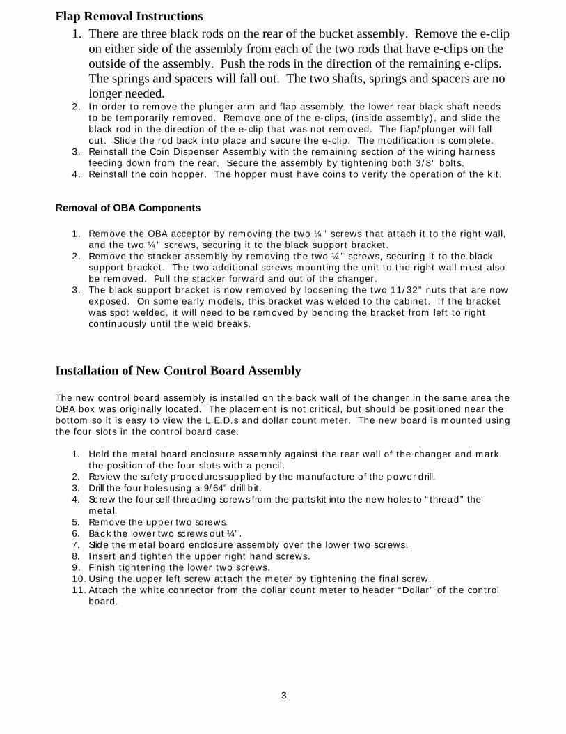
Flap Removal Instructions 1. There are three black rods on the rear of the bucket assembly. Remove the e-clip
on either side of the assembly from each of the two rods that have e-clips on the outside of the assembly. Push the rods in the direction of the remaining e-clips. The springs and spacers will fall out. The two shafts, springs and spacers are no longer needed.
2. In order to remove the plunger arm and flap assembly, the lower rear black shaft needs to be temporarily removed. Remove one of the e-clips, (inside assembly), and slide the black rod in the direction of the e-clip that was not removed. The flap/plunger will fall out. Slide the rod back into place and secure the e-clip. The modification is complete.
3. Reinstall the Coin Dispenser Assembly with the remaining section of the wiring harness feeding down from the rear. Secure the assembly by tightening both 3/8” bolts.
4. Reinstall the coin hopper. The hopper must have coins to verify the operation of the kit.
Removal of OBA Components
1. Remove the OBA acceptor by removing the two ¼” screws that attach it to the right wall, and the two ¼” screws, securing it to the black support bracket.
2. Remove the stacker assembly by removing the two ¼” screws, securing it to the black support bracket. The two additional screws mounting the unit to the right wall must also be removed. Pull the stacker forward and out of the changer.
3. The black support bracket is now removed by loosening the two 11/32” nuts that are now exposed. On some early models, this bracket was welded to the cabinet. If the bracket was spot welded, it will need to be removed by bending the bracket from left to right continuously until the weld breaks.
Installation of New Control Board Assembly The new control board assembly is installed on the back wall of the changer in the same area the OBA box was originally located. The placement is not critical, but should be positioned near the bottom so it is easy to view the L.E.D.s and dollar count meter. The new board is mounted using the four slots in the control board case.
1. Hold the metal board enclosure assembly against the rear wall of the changer and mark the position of the four slots with a pencil.
2. Review the safety procedures supplied by the manufacture of the power drill. 3. Drill the four holes using a 9/64” drill bit. 4. Screw the four self-threading screws from the parts kit into the new holes to “thread” the
metal. 5. Remove the upper two screws. 6. Back the lower two screws out ¼”. 7. Slide the metal board enclosure assembly over the lower two screws. 8. Insert and tighten the upper right hand screws. 9. Finish tightening the lower two screws. 10. Using the upper left screw attach the meter by tightening the final screw. 11. Attach the white connector from the dollar count meter to header “Dollar” of the control
board.
3
Routing the Wiring Harnesses 1. Connect the 7-position straight connector from the Coin Dispenser Assembly to Header
C2. 2. Connect the 3-position male connector from the main power box to Header P1.
Connect the 2-position straight connector from the empty bulb to Header “Empty”. The harness that connects to connector ” Empty” on the control board will only have two wires, however the connector has 3 pins. The center pin is ground, and pins 1 and 2 +5vdc. The harness can be attached to either pins 1 and 2 or 2 and 3. One pin will be left open.
3. The harness from P6 will attach to a 120 volt Mars AE/VN validator. 4. The by-pass jumper on header C3 may be removed after confirming proper operation of
the kit.
Validator and Control Board Update Instructions for BC1
Mount the Validator The existing hole in the front door is enlarged to the size of an industry standard validator mask. The instructions below are for both downstacker and upstacker validators. Before cutting the changer’s door, be sure to review the safety instructions supplied with your drill and jigsaw. Always wear safety goggles while drilling and cutting. Depending upon your preference, the validator mounting hole may be cut with the door attached to the changer or with it removed. If you will be cutting the hole with the door attached, it is helpful to close the door of the changer. The door can be removed by unscrewing the 15 screws that secure it to the hinge.
1. Use the hole for the original OBA as a reference point for enlarging the hole for mounting the validator. Place the sticker template so that the top of the existing hole aligns with the top of the template. Be sure to orient the label properly for either a downstacker or an upstacker installation.
2. The larger validator mounting hole in the front door of the changer is now cut. Place the drilling template on the front door of the changer.
3. Drill the four stud holes per the markings on the drilling label. Remove the label. 4. Insert the metal validator mounting bezel so the 4 studs go through the new holes. Once
the bezel is flush against the front door use a pointed tool to scratch the paint along the inside border of the bezel. A pencil could also be used. This is the area that will be cut using the jigsaw.
5. Use your jigsaw with high quality metal blades to cut out the new hole. Begin at the right hand side using the existing hole from the OBA acceptor as the guide.
6. Clean up the metal shavings. If there are rough edges around the newly cut area they should be removed using a file.
7. Set the dip switches on the validator per the guide that is silk screened onto the top left corner of the board enclosure. The settings are also listed below.
8. Secure the validator to the changer’s door using the validator mounting bracket. The four 11-32 hex nuts are supplied in the box with the Mars validator. A short 12” harness will be attached to the validator. Remove this harness, as it is not used with the kit.
9. Attach the harness from Header C4 for the control board to the validator. Be sure to observe the position of the two key pins.
4

Programming Information When the board is shipped it will be set to dispense four coins for each dollar value inserted. Dip switch 3 will be ON. Do not make any changes until proper operation of the new kit has been confirmed. The payout is programmed by selecting how many coins will be paid out for each dollar value. 1 coin is dispensed when “On” 2 coins are dispensed when “On” 4 coins are dispensed when “On” 8 coins are dispensed when “On”
Dip Switch Settings AE2400 $1-$5 AE2600 $1-$20 VN2500 $1-$5
1. ON 1. ON 1. ON
2. ON 2. ON 2. ON
3. OFF 3. ON 3. OFF
4. ON 4. OFF 4. ON
5. ON 5. OFF 5. ON
6. ON 6. OFF 6. ON
7. OFF 7. OFF 7. ON
8. ON 8. ON 8. OFF
Final Setup and Testing At this point, the kit can be tested. Plug the changer back into the wall outlet. The kit should have power. The red L.E.D. indicating +5vdc and the yellow L.E.D. indicating +12vdc will be illuminating. If not, check the ON/OFF switch on the new control board. The green arrows on the validator will begin blinking after a 10 second warm up period. The incandescent count bulb will NOT be lit. Insert bills and test the kit. Once a bill is verified, the incandescent count bulb will illuminate and the hopper motor will begin running.
Installation Instructions for Hopper “Low Coins” Screw (Rowe BC1, SBC2/4, and BC100 Changers)
Upon verifying the kit and changer are working properly, a low coins screw can be installed. The low coins screw must be installed to prevent shortchanging a customer. If the changer is in an attended location and the hopper will not empty, it is not necessary to install the low coins screws. The by-pass jumper is installed on header C3 when the kits are shipped. The screw is used to detect ground through the coins in the hopper. When the coins are not touching the screw and metal wall of the hopper, the changer will no longer accept bills. The reset button on the control board must be depressed after the hopper has been filled to reset the board.
5
Installation Instructions 1. Turn off the changer. 2. Remove the hopper form the changer and set it in a work area. If it is filled with coins,
remove the coins. 3. Drill an 11/64” hole in the black plastic area at the bottom of the hopper. The hole should
be located at the center of the hopper and 7/8” from the very bottom of the plastic. Positioning is important so that a coin does not get wedged between the screw and the hopper body.
4. Insert the screw through the hole. Reach your hand into the hopper and align the nut. Begin tightening the screw while holding the nut. When the nut is almost fully tightened, slip the open fork terminal under the screw head. Finish tightening the screw so the harness is held securely in place.
5. Loosen one of the ¼” hex screws on the lower section of the hopper. Place the remaining fork terminal under the screw and tighten the screw.
6. Place the hopper back in the changer. 7. Run the harness over the control board. Unplug the by-pass Jumper at C3 and attach the
new harness. 8. Secure the harness neatly in the changer using the tie mounts supplied in the parts kit. 9. Refill the hopper with coins so the screw is covered. 10. Turn on the changer. After a 10-second warm-up period, the validator will accept bills. 11. Place the label on hopper that warns service personnel not to remove hopper without
removing the empty sensor wire.
TROUBLESHOOTING TIPS The status LED on the control board will display the following codes: 1 Blink – Hopper is empty or has no continuity from harness to control board 2 Blinks – Time out feature; the maximum allowed time of 20 seconds between coin counts was exceeded 3 Blinks – Over payment of coins 4 Blinks – The incandescent count bulb is bad or is covered – the counting collector (across from emitter) may be bad. The lamp will not illuminate until the change making cycle begins. 5 Blinks – The control board’s dip switches are not set, thus no payout is possible If the +5vdc LED on the board is not lit check the following:
1. Wall outlet has power and the machines power cord is in excellent condition. 2. The on/off switch on the power input line is in the “on” position.
3. Unplug the machine and confirm that fuse #1 on the control board is good. It is a 2 amp fuse; 20mm.
The input button on the control board can be used to simulate pulses from a dollar bill validator to test the board. This button must be pressed rapidly. It must be pressed once, twice, five, ten, or twenty times as the board will shut down if an impossible dollar value is entered. The pulses must be inputted quickly. If the board shuts down depress the reset button.
6

OVERVIEW The green hopper LED lights while the hopper is running The meter clicks once per dollar value at the end of the vend cycle The new control board does not continuously supply power to the incandescent bulb used to count the coins. This helps to extend the life of the bulb. Once a bill has been accepted, the bulb will illuminate and the hopper will begin to payout coins. If the bulb fails, the board will shut down and the status LED will blink 4 times. The reset button on the board will need to be depressed after the bulb is replaced. The harness that connects to Header ” Empty” on the control board will only have two wires, however the connector has 3 pins. The center pin is ground, and pins 1 and 2 +5vdc. The harness can be attached to either pins 1 and 2 or 2 and 3. One pin will be left open. The input and reset buttons are located to the right of the voltage LEDS. When depressing a button a non-conductive slim tool should be used.
Technical Assistance Prior to calling please confirm the dip switches on the validator match the required settings. This is our most frequent phone call. Technical Assistance for kit part number KITRBDBC1-MAEVN is available from 9:00am – 4:00pm EST at (800) 814-7756. Revision 020905
7
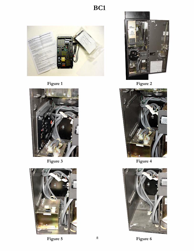
8
Figure 6
Figure 4
Figure 2
BC1
Figure 3
Figure 5
Figure 1
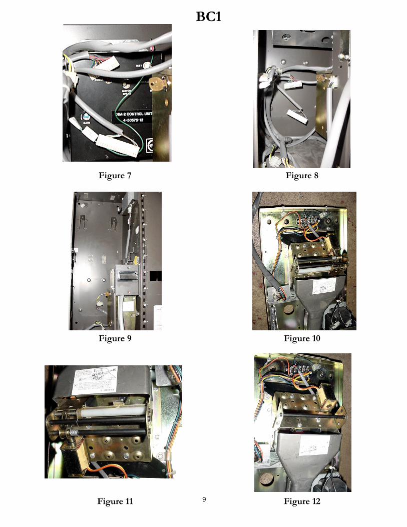
9
Figure 12
Figure 10
Figure 8
Figure 9
Figure 11
Figure 7
BC1
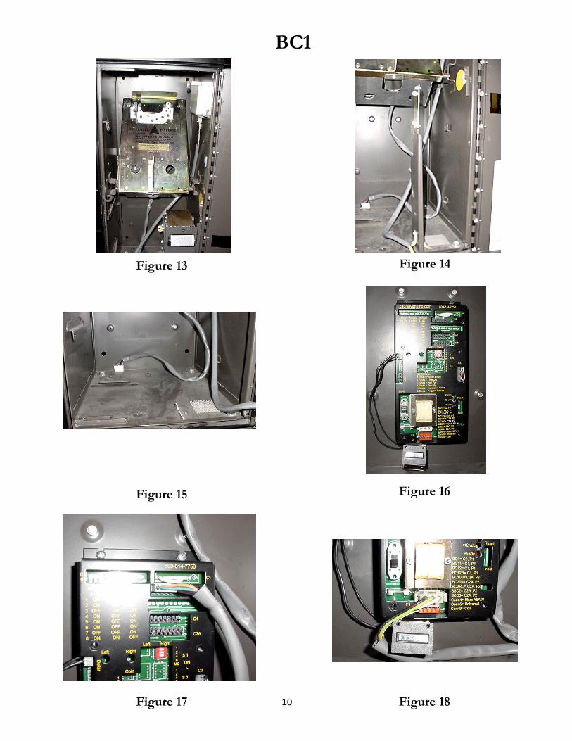
Figure 16
Figure 14
Figure 15
Figure 13
BC1
Figure 18 10Figure 17

Figure 19
BC1
11

Bullet Bulb for Rowe Changers
This custom part replaces the 755 incandescent count emitter bulb in Rowe dollar bill changers. This part is installed in the coin dispenser assembly that is located behind the hoppers. This new part offers the advantage of a considerably longer life and will not fail due to vibrations. This is very important as Rowe changers shut down when the count emitter bulb fails. This item easily pays for it self by eliminating service calls and unnecessary downtime. The “Bullet Bulb” can be installed in a bill changer that originally used an incandescent lamp BC2RC, SCC3, BC9, C10, BC11, BC115, BC12, BC12R, BC20, BC25, BC25MC, and BC35. Part# NRBULLETBULB $9.95 For Rowe changer models BC100, BC150, BC200, BC1200, BC1400, BC2800, and BC3500. Part # NRBULBxx00 $9.95 Installation: On location installation time of 5 minutes or less. Tools Required: Regular screwdriver, 3/8” socket or pliers to remove the 2 bolts securing the coin dispenser assembly.
12