Validating In-Building Wireless Coverage of Public Safety ...
7
Application Brief Validating In-Building Wireless Coverage of Public Safety, LTE, and Wi-Fi ® Networks Meet Public Safety Requirements and Overcome Key Technical Challenges to In-Building Coverage Mapping This application brief will explain how to conduct radio frequency coverage mapping testing utilizing an Anritsu MS27101A-IBCM In-Building Coverage Mapping bundle made up of a Remote Spectrum Monitor MS27101A and NEON ® Signal Mapper MA8100A solutions. Application Description Validating wireless network coverage for in-building applications presents a few different challenges for contractors and network engineers. There are both legal requirements to satisfy as well as technical challenges to overcome. This product brief defines a methodology to meet both conditions using the Anritsu MS27101A-IBCM In-Building Coverage Mapper product. With the advent of public safety networks such as P25 and TETRA, many governments and municipalities worldwide require guaranteed coverage validation for new and existing buildings. While exact regulations can vary from region to region, a good example is the US-based NFPA 72 requirement for in-building DAS and Wi-Fi systems: “Critical areas, such as the fire command center(s), the fire pump room(s), exit stairs, exit passageways, elevator lobbies, standpipe cabinets, sprinkler sectional valve locations, and other areas deemed critical by the authority having jurisdiction, shall be provided with 99 percent floor area radio coverage.” While the general scope may be clear and concise, the actual implementation of validating coverage presents some technical challenges. First and foremost, a GPS signal, which is the most common way for analysis tools to coordinate position data with any kind of test data results, is notoriously unreliable inside buildings, especially multi-story ones. If multiple level basements are included, correlating coverage RF data with position becomes almost impossible. This lack of GPS signal is especially evident in the “critical areas” defined in the NFPA72 specification clause above. In particular, exit stairs, standpipe cabinets, and sprinkler sectional valve controls are all areas that are isolated (for good reason) from main areas making GPS signal availability even more sparse.
Transcript of Validating In-Building Wireless Coverage of Public Safety ...

Application Brief
Validating In-Building Wireless Coverage of Public Safety, LTE, and Wi-Fi® NetworksMeet Public Safety Requirements and Overcome Key Technical Challenges to In-Building Coverage Mapping
This application brief will explain how to conduct radio frequency coverage mapping testing utilizing an Anritsu MS27101A-IBCM In-Building Coverage Mapping bundle made up of a Remote Spectrum Monitor MS27101A and NEON® Signal Mapper MA8100A solutions.
Application DescriptionValidating wireless network coverage for in-building applications presents a few different challenges for contractors and network engineers. There are both legal requirements to satisfy as well as technical challenges to overcome. This product brief defines a methodology to meet both conditions using the Anritsu MS27101A-IBCM In-Building Coverage Mapper product.
With the advent of public safety networks such as P25 and TETRA, many governments and municipalities worldwide require guaranteed coverage validation for new and existing buildings. While exact regulations can vary from region to region, a good example is the US-based NFPA 72 requirement for in-building DAS and Wi-Fi systems:
“Critical areas, such as the fire command center(s), the fire pump room(s), exit stairs, exit passageways, elevator lobbies, standpipe cabinets, sprinkler sectional valve locations, and other areas deemed critical by the authority having jurisdiction, shall be provided with 99 percent floor area radio coverage.”
While the general scope may be clear and concise, the actual implementation of validating coverage presents some technical challenges. First and foremost, a GPS signal, which is the most common way for analysis tools to coordinate position data with any kind of test data results, is notoriously unreliable inside buildings, especially multi-story ones. If multiple level basements are included, correlating coverage RF data with position becomes almost impossible.
This lack of GPS signal is especially evident in the “critical areas” defined in the NFPA72 specification clause above. In particular, exit stairs, standpipe cabinets, and sprinkler sectional valve controls are all areas that are isolated (for good reason) from main areas making GPS signal availability even more sparse.
2
In terms of the technical challenges, the main one relates to the practicality of building contractors having to harbor this responsibility. While in-building networks do not have legal requirements for the commercial side, there still may be occupancy permit requirements from the building owners requiring a certain coverage guarantee. While current standards state that only a single network must be validated (say a P25 public safety network), the reality is that most modern networks have multiple in-building bands that will all require validation and this is where problems can arise. If building contractors have to perform an RF scanning exercise for each band, the testing exercise will multiply linearly by the number of bands to validate the entire building. This will bear a huge cost for the building contractors. Ideally, there would be only walkthrough that can validate everything simultaneously.
The Solution: MS27101A-IBCM In-Building Coverage MapperThe MS27101A-IBCM In-Building Coverage Mapper solution is designed specifically to address the challenges that come with validating an in-building network. The solution does not require a GPS signal, instead using a local “tracker” to coordinate its position with the RF readings so a true 3D map can be created. This enables technicians to easily pinpoint weak or no-coverage areas and address them appropriately. This also aids in the documentation for legal requirements.
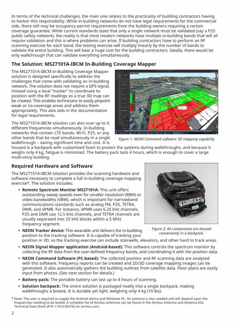
The MS27101A-IBCM solution can also scan up to 6 different frequencies simultaneously. In-building networks that contain LTE bands, Wi-Fi, P25, or any other bands that be read simultaneously in a single walkthrough – saving significant time and cost. It is housed is a backpack with customized foam to protect the systems during walkthroughs, and because it weighs only 4 kg, fatigue is minimized. The battery pack lasts 4 hours, which is enough to cover a large multi-story building.
Required Hardware and SoftwareThe MS27101A-IBCM solution provides the scanning hardware and software necessary to complete a full in-building coverage mapping exercise*. The solution includes:
• Remote Spectrum Monitor MS27101A: This unit offers outstanding sweep speeds even for smaller resolution (RBW) or video bandwidths (VBW), which is important for narrowband communications standards such as analog FM, P25, TETRA, DMR, and dPMR. For instance, dPMR uses 6.25 kHz channels, P25 and DMR use 12.5 kHz channels, and TETRA channels are usually separated into 25 kHz blocks within a 5 MHz frequency segment.
• NEON Tracker device: This wearable unit delivers the in-building position to the tracking software. It is capable of tracking your position in 3D, so the tracking exercise can include stairwells, elevators, and other hard to track areas.
• NEON Signal Mapper application (Android-based): This software controls the spectrum monitor by collecting the RF data from the user-defined frequency bands, and coordinating it with the position data.
• NEON Command Software (PC-based): The collected position and RF scanning data are analyzed with this software. Frequency reports can be created and 2D/3D coverage mapping images can be generated. It also automatically gathers the building outlines from satellite data. Floor plans are easily input from photos. (See next section for details.)
• Battery pack: The portable battery can last up to 4 hours of scanning. • Solution backpack: The entire solution is packaged neatly into a single backpack, making
walkthroughs a breeze. It is durable yet light, weighing only 4 kg (10 lbs).
* Note: The user is required to supply the Android device and Windows PC. An antenna is also needed and will depend upon the frequencies needing to be tested. A complete list of Anritsu antennas can be found in the Anritsu Antenna and Antenna Kits Technical Data Sheet (P/N 11410-00376) on anritsu.com.
Figure 2: All components are housed conveniently in a backpack.
Figure 1: NEON Command software 3D mapping capability

3
Setting up the In-Building Coverage MapperThere are 5 steps to setting up the MS27101A-IBCM solution for testing:
1. Check for proper device communication2. Set scanning frequencies.3. Import building outline and floor plan4. Calibrate tracker with your in-building position.5. Display and analyze data.
Before starting the sequence below, the hardware needs to go through a one-time setup process. This can be found in the MS27101-IBCM Quick Start Guide on anritsu.com.
Step 1: Checking the Communication InterfaceTo perform a communication test between the Remote Spectrum Monitor MS27101A and the Android device, open a web browser on the Android device and type in the IP address of the Remote Spectrum Monitor unit (192.168.0.150).
The screen shown in Figure 3 will appear. If it does not, please refer to the MS27101A-IBCM Quick Start Guide to troubleshoot the problem.
Once communication with the Remote Spectrum Monitor MS27101A has been verified, you can close the web browser and setup the NEON Signal Mapper application.
Step 2: Configuration of the NEON Signal Mapper Application for Multi-Frequency TrackingThe following steps will configure the NEON Signal Mapper application:
1. Open the NEON Signal Mapper application on the Android device.
2. Go to Anritsu Settings → Device IP Address. Enter the IP address of the Remote Spectrum Monitor (192.168.0.150).
3. Go to Anritsu Setting → Anritsu Channel Scanner Setup. Hit ADD CHANNEL and enter all frequencies of interest by defining frequency, SPAN, RBW, and Ref Level. Click OK to confirm the settings (Figure 4).
Note: The Remote Spectrum Monitor hardware can support frequencies from 9 kHz to 6 GHz, making it appropriate for all current public safety, LTE, and Wi-Fi bands
Figure 4: Enter frequencies that need to be scanned
Figure 3: Verifying communication between the Android device and the Remote Spectrum Monitor
4
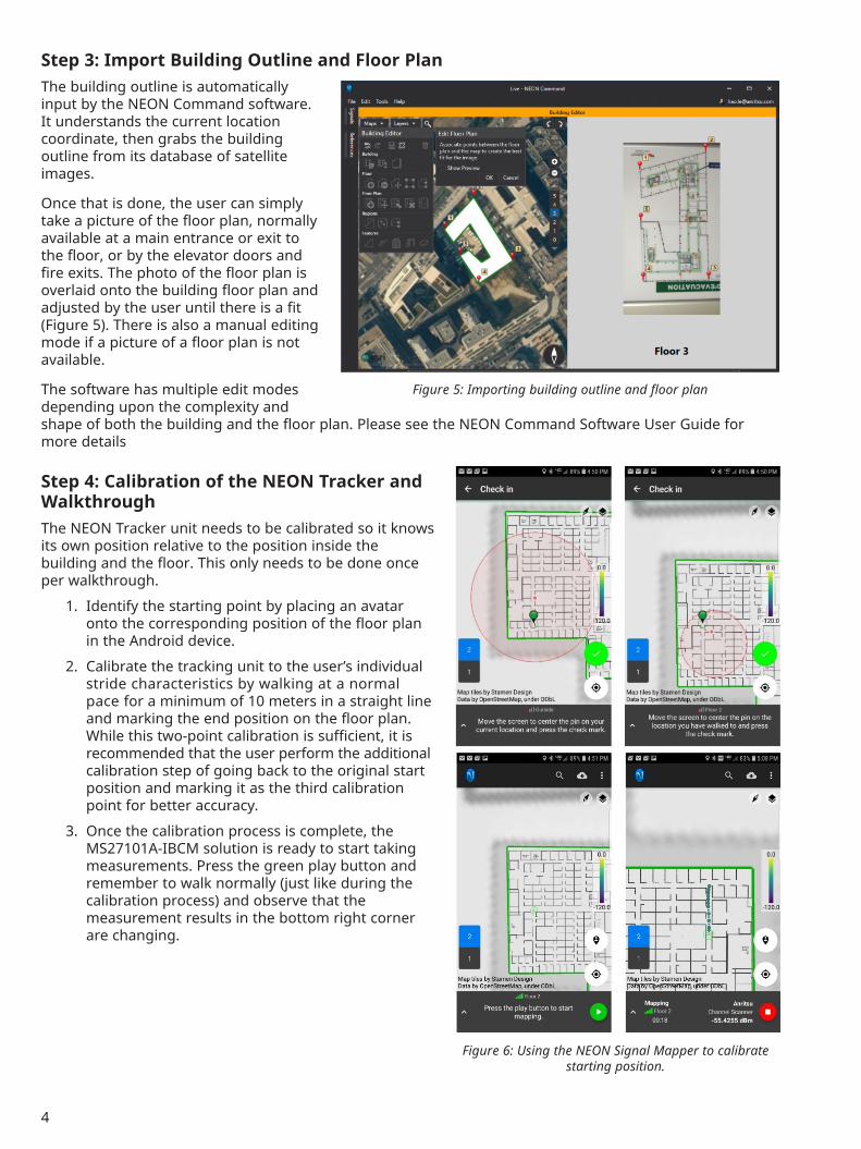
Step 3: Import Building Outline and Floor PlanThe building outline is automatically input by the NEON Command software. It understands the current location coordinate, then grabs the building outline from its database of satellite images.
Once that is done, the user can simply take a picture of the floor plan, normally available at a main entrance or exit to the floor, or by the elevator doors and fire exits. The photo of the floor plan is overlaid onto the building floor plan and adjusted by the user until there is a fit (Figure 5). There is also a manual editing mode if a picture of a floor plan is not available.
The software has multiple edit modes depending upon the complexity and shape of both the building and the floor plan. Please see the NEON Command Software User Guide for more details
Step 4: Calibration of the NEON Tracker and WalkthroughThe NEON Tracker unit needs to be calibrated so it knows its own position relative to the position inside the building and the floor. This only needs to be done once per walkthrough.
1. Identify the starting point by placing an avatar onto the corresponding position of the floor plan in the Android device.
2. Calibrate the tracking unit to the user’s individual stride characteristics by walking at a normal pace for a minimum of 10 meters in a straight line and marking the end position on the floor plan. While this two-point calibration is sufficient, it is recommended that the user perform the additional calibration step of going back to the original start position and marking it as the third calibration point for better accuracy.
3. Once the calibration process is complete, the MS27101A-IBCM solution is ready to start taking measurements. Press the green play button and remember to walk normally (just like during the calibration process) and observe that the measurement results in the bottom right corner are changing.
Figure 5: Importing building outline and floor plan
Figure 6: Using the NEON Signal Mapper to calibrate starting position.

5
Step 5: Display and Analysis of the Measurement DataAt the end of the walk-through, save the measurement data either locally to the Android device (if it is sensitive and confidential data) or upload it to the included TRX Cloud Storage service. To process and display the data, open the file in the NEON Command software, and select the frequencies of interest to plot, and click on the Generate Map button. This will generate a coverage map of the entire walkthrough area and show color coded RF levels.
For more formal reporting, coverage reports showing the floor plan with a heat map overlay are available to export in PDF format. Options are available to display the data across a grid, show only individual frequencies scanned, or display the exact location dot of the RF measurement. Formal reporting will help provide the documentation necessary to satisfy compliance requirements.
Figure 8: Formal grid report showing floor plan with heat map overlay
Figure 7: Results of a multi-frequency coverage mapping measurement in NEON Command software

6
ConclusionThe MS27101A-IBCM In-Building Coverage Mapper solution is a complete software and hardware package that allows easy coverage mapping of single or multi-story buildings. It overcomes a major challenge of doing an in-building coverage exercise as it does not require a GPS signal to do its testing. This give the solution the ability to provide coverage mapping of traditionally difficult areas such as stairwells, elevators, and other areas critical to public safety requirements.
The 5-step process to import building floor plan data, calibrate position, complete the walk-through, and analyze the results is simple and straightforward. Analysis results can be stored locally in the required Android device for security purposes or uploaded to the cloud for reporting convenience. The results can be displayed in 2D or 3D so engineers can visually inspect for weak coverage areas.
Several features are built into the solution for both convenience as well as time and cost savings. It is housed in a light, all-in-one backpack so technicians are not burdened with cumbersome equipment. Multiple frequencies can be scanned in a single walk-through, saving expensive manpower costs. It also has 4-hour battery life, giving it the ability to do a large multi-story building in a single charge. Finally, the hardware can support from 9 kHz to 6 GHz, which supports all current public safety, LTE, and Wi-Fi bands.
Figure 9: Results of a multi-frequency coverage mapping measurement in NEON Command software

11410-01194, Rev. A Printed in United States 2020-05©2020 Anritsu Company. All Rights Reserved.
® Anritsu All trademarks are registered trademarks of their respective companies. Data subject to change without notice. For the most recent specifications visit: www.anritsu.com
• United States Anritsu Company450 Century Parkway, Suite 190, Allen, TX 75013 U.S.A. Phone: +1-800-Anritsu (1-800-267-4878)
• Canada Anritsu Electronics Ltd.700 Silver Seven Road, Suite 120, Kanata, Ontario K2V 1C3, Canada Phone: +1-613-591-2003 Fax: +1-613-591-1006
• Brazil Anritsu Electrônica Ltda.Praça Amadeu Amaral, 27 - 1 Andar 01327-010 - Bela Vista - Sao Paulo - SP - Brazil Phone: +55-11-3283-2511 Fax: +55-11-3288-6940
• Mexico Anritsu Company, S.A. de C.V.Blvd Miguel de Cervantes Saavedra #169 Piso 1, Col. Granada Mexico, Ciudad de Mexico, 11520, MEXICO Phone: +52-55-4169-7104
• United Kingdom Anritsu EMEA Ltd.200 Capability Green, Luton, Bedfordshire LU1 3LU, U.K. Phone: +44-1582-433200 Fax: +44-1582-731303
• France Anritsu S.A.12 avenue du Québec, Batiment Iris 1-Silic 612, 91140 VILLEBON-SUR-YETTE, France Phone: +33-1-60-92-15-50 Fax: +33-1-64-46-10-65
• Germany Anritsu GmbHNemetschek Haus, Konrad-Zuse-Platz 1 81829 München, Germany Phone: +49-89-442308-0 Fax: +49-89-442308-55
• Italy Anritsu S.r.l.Via Elio Vittorini 129, 00144 Roma Italy Phone: +39-06-509-9711 Fax: +39-6-502-2425
• Sweden Anritsu ABIsafjordsgatan 32C, 164 40 KISTA, Sweden Phone: +46-8-534-707-00
• Finland Anritsu ABTeknobulevardi 3-5, FI-01530 VANTAA, Finland Phone: +358-20-741-8100 Fax: +358-20-741-8111
• Denmark Anritsu A/Sc/o Regus Fairway, Arne Jacobsens Allé 7, 5th floor, 2300 Copenhagen S, Denmark Phone: +45-7211-2200
• Russia Anritsu EMEA Ltd. Representation Office in RussiaTverskaya str. 16/2, bld. 1, 7th floor. Moscow, 125009, Russia Phone: +7-495-363-1694 Fax: +7-495-935-8962
• Spain Anritsu EMEA Ltd. Representation Office in SpainPaseo de la Castellana, 141. Planta 5, Edificio Cuzco IV 28046, Madrid, Spain Phone: +34-91-572-6761
• United Arab Emirates Anritsu EMEA Ltd. Dubai Liaison Office902, Aurora Tower, P O Box: 500311- Dubai Internet City Dubai, United Arab Emirates Phone: +971-4-3758479 Fax: +971-4-4249036
• India Anritsu India Pvt Ltd.6th Floor, Indiqube ETA, No.38/4, Adjacent to EMC2, Doddanekundi, Outer Ring Road, Bengaluru – 560048, India Phone: +91-80-6728-1300 Fax: +91-80-6728-1301
• Singapore Anritsu Pte. Ltd.11 Chang Charn Road, #04-01, Shriro House Singapore 159640 Phone: +65-6282-2400 Fax: +65-6282-2533
• Vietnam Anritsu Company LimitedRoom No. 1635, 16th Floor, ICON 4 Tower, 243A De La Thanh Street, Lang Thuong Ward, Dong Da District, Hanoi, Vietnam Phone: +84-24-3760-6216 Fax: +84-24-6266-2608
• P. R. China (Shanghai) Anritsu (China) Co., Ltd.Room 2701-2705, Tower A, New Caohejing International Business Center No. 391 Gui Ping Road Shanghai, 200233, P.R. China Phone: +86-21-6237-0898 Fax: +86-21-6237-0899
• P. R. China (Hong Kong) Anritsu Company Ltd.Unit 1006-7, 10/F., Greenfield Tower, Concordia Plaza, No. 1 Science Museum Road, Tsim Sha Tsui East, Kowloon, Hong Kong, P. R. China Phone: +852-2301-4980 Fax: +852-2301-3545
• Japan Anritsu Corporation8-5, Tamura-cho, Atsugi-shi, Kanagawa, 243-0016 Japan Phone: +81-46-296-6509 Fax: +81-46-225-8352
• Korea Anritsu Corporation, Ltd.5FL, 235 Pangyoyeok-ro, Bundang-gu, Seongnam-si, Gyeonggi-do, 13494 Korea Phone: +82-31-696-7750 Fax: +82-31-696-7751
• Australia Anritsu Pty Ltd.Unit 20, 21-35 Ricketts Road, Mount Waverley, Victoria 3149, Australia Phone: +61-3-9558-8177 Fax: +61-3-9558-8255
• Taiwan Anritsu Company Inc.7F, No. 316, Sec. 1, NeiHu Rd., Taipei 114, Taiwan Phone: +886-2-8751-1816 Fax: +886-2-8751-1817
Specifications are subject to change without notice.


![Axell Wireless Cellular Coverage Solutions Brochure[1]](https://static.fdocuments.us/doc/165x107/55cf98a6550346d03398df7e/axell-wireless-cellular-coverage-solutions-brochure1.jpg)