Vacuum Pad with Ejectorca01.smcworld.com/catalog/en/vacuum/ZHP-E/6-4-p... · First ejector Second...
8
Two-stage ejector Ejector silencer Prevents entry of foreign matter at the pad suction port. Strainer Metric: ø4, ø6 Inch: ø5/32", ø1/4" With One-touch fitting Daisy-chain piping Daisy-chain vacuum piping is possible. <Daisy-chain piping example> Port/For Vacuum release, Pressure sensor, Daisy-chain piping ∗ 1) Compared with SMC single stage ejector More efficient ejector With ejector Without ejector SUP ¡Structure designed to minimize clogging A shot-blasted die is used to create micro-dents and bumps on the adsorption surface. Workpieces can be removed easily. ∗2 Compared with current ZP series Dents and bumps on the adsorption surface prevent the workpiece from sticking to it. This facilitates easy removal. With groove Shot-blasted die Improved ease of removal ∗2 Flat type with groove Bellows type with groove By dispersing the exhaust in all directions, undesired exhaust noise can be silenced while still exhibiting maximum vacuum performance. Suction flow rate Air consumption First ejector Second ejector Q1 + Q2 = Suction flow rate Two-stage ejector 30% reduced ∗1 50% increased ∗1 EXH EXH Silencer Vacuum Pad with Ejector Pad Diameter: ø63, ø80 ZHP Series RoHS 253 Ejector and pad are integrated. Space saving and reduced piping labor! ZK2 ZQ ZR ZA ZB ZX ZM ZL ZH ZH ZU ZH -X267 VQD-V ZHP c
Transcript of Vacuum Pad with Ejectorca01.smcworld.com/catalog/en/vacuum/ZHP-E/6-4-p... · First ejector Second...

Two-stage ejector
Ejector silencer
Prevents entry of foreign matterat the pad suction port.
Strainer
Metric: ø4, ø6Inch: ø5/32", ø1/4"
With One-touch fitting
Daisy-chainpiping
Daisy-chain vacuum piping is possible.<Daisy-chain piping example>
Port/For Vacuum release, Pressure sensor, Daisy-chain piping
∗ 1) Compared with SMC single stage ejector
More efficient ejector
With ejector Without ejector
SUP
¡Structure designed to minimize clogging
A shot-blasted die is used to create micro-dents and bumps on the adsorption surface. Workpieces can be removed easily.
∗2 Compared with current ZP series
Dents and bumps on the adsorption surface prevent the workpiece from sticking to it. This facilitates easy removal.
With groove
Shot-blasted die
Improved easeof removal∗2
Flat typewith groove
Bellows typewith groove
By dispersing the exhaust in all directions, undesired exhaust noise can be silenced while still exhibiting maximum vacuum performance.
Suctionflow rate
Airconsumption
First ejector Second ejector
Q1 + Q2 = Suction flow rate
Two-stage ejector
30% reduced∗150% increased∗1
EXHEXH
Silencer
Vacuum Pad with Ejector
Pad Diameter: ø63, ø80
ZHP Series
RoHS
253
Ejector and pad are integrated.Space saving and reduced piping labor!
ZK2
ZQ
ZR
ZA
ZB
ZX
ZM
ZL
ZH
ZH
ZU
ZHP
ZH-X267
VQD-V
ZHP
c

Uses an isolated structure.
Remove the lock screwand slide the lock plate.
Remove the stud fromthe bottom of the pad.
Lock plate
Stud
q
w
Lock screw
¡A lock plate is used to facilitate separation.¡Rubber and metal parts can be disposed of separately.
Mounting with the lock plate reduces the pad replacement work steps!
Easier maintenance
Holder
Holder
Plate
Pad
Robot handlingPalletizing
Automobile Case packer
Application Examples
ZHP Series
254
Pad diameter Pad form Pad material Mounting Nozzle nominal size *2 [mm]
ø63, ø80Bellows typewith groove
Flat typewith groove
NBR (Black) *1
Silicone rubber (White)Urethane rubber (Brown)FKM (Black) *1
Metric size (Male thread/Female thread)M8M10
Inch size (Male thread/Female thread)5/16-18UNC3/8-16UNC
ø0.7ø1.0ø1.2ø1.5
*1 Refer to page 260 for identification method.
*2 With ejector
A

∗ Refer to page 260 for identification method.
Pad formBM Bellows type with grooveUM Flat type with groove
BM
BM
wWeight Difference by Material [g]Pad diameter/form Silicone rubber Urethane rubber FKMZHP63BM −2.9 0 20.3ZHP80BM −5.0 0 35.1ZHP63UM −1.5 0 10.6ZHP80UM −2.1 0 15.5
RoHS
How to Order
Pad diameter63 ø6380 ø80
Exhaust releaseS Silencer exhaust
Pad materialN NBR (Black)∗S Silicone rubber (White)U Urethane rubber (Brown)F FKM (Black)∗
MountingSymbol Type Thread SizeA
Metricsize
Malethread
M8B M10C Female
threadM8
D M10E
Inchsize
Malethread
5/16-18UNCF 3/8-16UNCG Female
thread5/16-18UNC
H 3/8-16UNC
Ejector/Nozzle nominal size [mm]07 Nozzle: ø0.710 Nozzle: ø1.012 Nozzle: ø1.215 Nozzle: ø1.5
Supply (P) portSymbol Type Port size
C4Metric
ø4 One-touch fittingC6 ø6 One-touch fittingN3
Inchø5/32" One-touch fitting
N7 ø1/4" One-touch fitting
B
B
N
N
ZHP
ZHP
80
80
With ejector
Without ejector
10
00
Ejector Specifications
ZHP-07l ZHP-10 ZHP-12 ZHP-15Nozzle nominal size [mm] 0.7 1.0 1.2 1.5Max. suction flow rate [L/min (ANR)]∗ 30 52 63 78Air consumption [L/min (ANR)]∗ 24 40 58 87Vacuum pressure reached [kPa] −91Standard supply pressure [MPa] 0.35
∗ Standard supply pressure
Recommended Work Load [N]
ZHP63 ZHP80Horizontal lifting 66 106
Vertical lifting 33 53
Use this product with the recommended work load or less. The transfer work over the recommended work load may cause the vacuum pressure to decrease by the air leak. The work load shown above is the value when the vacuum pressure reaches –85 kPa, and that is calculated by multiplying the theoretical value by a safety factor of “1/4” for the horizontal lifting or “1/8” for the vertical lifting. For details, refer to pages 25 to 48 for the Vacuum Equipment Model Selection. The vacuum pressure reached may var y depending on the workp iece (permeability, etc.) Calculate the actual work load in accordance with the vacuum pressure reached.
Response Time [ms]
ZHPBM-07 ZHPBM-10 ZHPBM-12 ZHPBM-15ø63 295 143 120 86ø80 455 221 190 140
Response time means a period of time that the vacuum pressure reaches –57 kPa after the externally installed valve has been turned ON when the bellows type pad is used and the supply pressure is 0.35 MPa.
Nozzle sizePad dia.
WeightMaterial: NBR, Mounting: A [g]
ZHP63BMNA-C6S 184ZHP80BMNA-C6S 224ZHP63UMNA-C6S 167ZHP80UMNA-C6S 175
For the ZHPA-00 (without ejector), weight shown above –12 g.When the mounting symbol is other than “A”, add the weight q shown in the table on
the right to the weight described in the table above.When the material is other than NBR, add the weight w shown in the table on the
right to the weight described in the table above.This weight includes the accessory weight.
qWeight Difference by Mounting Style [g]
B C D E F G H20 −5 14 7 25 1 11
S
Vacuum Pad with Ejector
ZHP Seriesø63, ø80
C6
255
ZK2
ZQ
ZR
ZA
ZB
ZX
ZM
ZL
ZH
ZH
ZU
ZHP
ZH-X267
VQD-V
ZHP
A

ZHP-07 (Supply pressure: 0.35 MPa)
−100
−80
−60
−40
−20
00 10 20 30 40
Suction flow [L/min(ANR)]
Vac
uum
pre
ssur
e [k
Pa]
Flow Rate CharacteristicsExhaust Characteristics
ZHP-10−100
−80
−60
−40
−20
00 10 20 40 50 6030
Suction flow [L/min(ANR)]
Vac
uum
pre
ssur
e [k
Pa]
ZHP-12−100
−80
−60
−40
−20
00 20 40 60 80
Suction flow [L/min(ANR)]
Vac
uum
pre
ssur
e [k
Pa]
ZHP-15
(Supply pressure: 0.35 MPa)
(Supply pressure: 0.35 MPa)
(Supply pressure: 0.35 MPa)
−100
−80
−60
−40
−20
00 20 40 60 80 100
Suction flow [L/min(ANR)]
Vac
uum
pre
ssur
e [k
Pa]
ZHP-07−100
−90
−80
−70
−60
−50
−40
−30
−20
−10
0
50
45
40
35
30
25
20
15
10
5
00 0.1 0.2 0.3 0.4 0.5 0.6
Supply pressure [MPa]
Vac
uum
pre
ssur
e [k
Pa]
Suc
tion
flow
[L
/min
(AN
R)]
Air
cons
umpt
ion
[L/m
in(A
NR
)]
ZHP-10−100
−90
−80
−70
−60
−50
−40
−30
−20
−10
0
100
90
80
70
60
50
40
30
20
10
00 0.1 0.2 0.3 0.4 0.5 0.6
Supply pressure [MPa]
Vac
uum
pre
ssur
e [k
Pa]
Suc
tion
flow
[L
/min
(AN
R)]
Air
cons
umpt
ion
[L/m
in(A
NR
)]
ZHP-12−100
−90
−80
−70
−60
−50
−40
−30
−20
−10
0
100
90
80
70
60
50
40
30
20
10
00 0.1 0.2 0.3 0.4 0.5 0.6
Supply pressure [MPa]
Vac
uum
pre
ssur
e [k
Pa]
Suc
tion
flow
[L
/min
(AN
R)]
Air
cons
umpt
ion
[L/m
in(A
NR
)]
ZHP-15−100
−90
−80
−70
−60
−50
−40
−30
−20
−10
0
150
135
120
105
90
75
60
45
30
15
00 0.1 0.2 0.3 0.4 0.5 0.6
Supply pressure [MPa]
Vac
uum
pre
ssur
e [k
Pa]
Suc
tion
flow
[L
/min
(AN
R)]
Air
cons
umpt
ion
[L/m
in(A
NR
)]
Vacuum pressure
Suction flow
Air consumption
Vacuum pressureSuction flow
Air consumption
Vacuum pressure
Suction flow
Air consumption
Vacuum pressure
Suction flow
Air consumption
Exhaust Characteristics/Flow Rate Characteristics (Representative Value)
ZHP Series
256A

Bellows type with groove Flat type with groove
Holder
Plate
A-A
u
y
q
!1
!5
r
e
w
!0
o
i
t !4!3!2
A A
No. Description Note
1 Stud
2 Strainer
3 Mounting bracket
4 Lock nut2 pcs. included for male thread mounting(Not included for female thread mounting)
5 Lock pin
6 Check valve
7 Lock plate
No. Description Part no. Note
8 Pad ZP3E-mmm Flat/Bellows type with groove
9 PlateZHP1-PLm-A
10 Holder
11 Plug∗ TB00148 Included for metric size
TB00055 Included for inch size
12 One-touch fitting KJHm-C2
13 Ejector assembly ZK2-EJmW-A
14 Silencer assembly ZHP1-SA1-A
15 Lock screw CA00284 Included
∗ 3 pieces are included in one product. (The part numbers are for 1 piece.)
Component Parts
Replacement Parts
Construction
Replacement Parts/How to Order
Pad diameter63 ø6380 ø80
∗ When changing the pad diameter, replace also the plate together.
Pad materialN NBRS Silicone rubberU Urethane rubberF FKM
Pad formBM Bellows type with grooveUM Flat type with groove
NZP3E 80 BMi Pad
!2 One-touch fitting (The order lot is 10 pieces.)
Applicable tubing O.D.04 ø406 ø603 ø5/32"07 ø1/4"
KJH C206
o!0 Plate assembly∗
Size (Applicable pad dia./form)1 ø63/ø80: Flat type, ø63: Bellows type2 ø80: Bellows type
∗ Part number for a set of plate and holder
ZHP1 PL A1
!3 Ejector assembly
Nozzle nominal size07 ø0.710 ø1.012 ø1.215 ø1.5
ZK2 EJ AW10
257
Vacuum Pad with Ejector ZHP Series
ZK2
ZQ
ZR
ZA
ZB
ZX
ZM
ZL
ZH
ZH
ZU
ZHP
ZH-X267
VQD-V
ZHP
A

PD2
PD1
PD3
EXH.P
V
EX
H.
In the case of Flat type
DCA
FE
P port
PD port 1
Unlocked: 32.2
Unlocked
Locked
DCBA
ø14.4
EF
6.2
L
Female threadmounting
M
P
Silencer
Male threadmounting
M
N 30 69.7
ø15
24.7
K
PD port 2
Lock screw
107.
86.
2
GH
J
7.3 1.4
P
6.2PD port 3
PD port sizeMetric size: Rc1/8Inch size: NPT1/8
Dimensions [mm]
A B C D E FZHP63BM ø26 ø45.8 ø63 ø68 12.5 33.8
ZHP80BM ø28 ø57 ø80 ø85 18 41.8
ZHP63UM ø26 — ø63 ø66 5 20.3
ZHP80UM ø26 — ø80 ø83 5 20.3
Supply Port Dimensions [mm]
NC4 4.7
C6 4.7
N3 4.7
N7 7.3
Adapter Dimensions (by Mounting Style) [mm]
G H J K L MZHPmmmA-mmS 25.7 22.6 5 13 — M8
ZHPmmmB-mmS 27.1 21.2 6 17 — M10
ZHPmmmC-mmS — — — 13 36.7 M8 depth 10
ZHPmmmD-mmS — — — 17 39.1 M10 depth 10
ZHPmmmE-mmS 27.45 21.8 6.75 12.7 — 5/16-18UNC
ZHPmmmF-mmS 29.43 26.82 8.33 14.28 — 3/8-16UNC
ZHPmmmG-mmS — — — 12.7 41.7 5/16-18UNC depth 11
ZHPmmmH-mmS — — — 14.28 44.1 3/8-16UNC depth 11
For symbols G and H (inch-type female thread), the dimension K becomes the width across flats.
Circuit
Dimensions
258
ZHP Series
A
Unlocked
qLock plate wLock screw
Adhesion
Stud
Gap
Locking status: Acceptable
Locking status: Not acceptable
e
r
y
t
w
q
Pad assembly
Lock plateLever on ejector side
Adapter plate
Lock plate
Lock screw
Plate
Non-rotating hole
Holder
Pad
Stud assembly
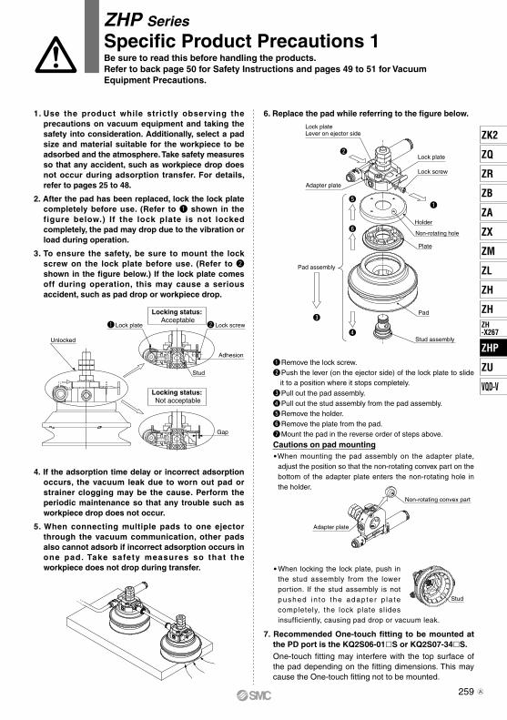
6. Replace the pad while referring to the figure below.
q Remove the lock screw.w Push the lever (on the ejector side) of the lock plate to slide
it to a position where it stops completely.e Pull out the pad assembly.r Pull out the stud assembly from the pad assembly.t Remove the holder.y Remove the plate from the pad.u Mount the pad in the reverse order of steps above.
Cautions on pad mountingWhen mounting the pad assembly on the adapter plate,
adjust the position so that the non-rotating convex part on the bottom of the adapter plate enters the non-rotating hole in the holder.
When locking the lock plate, push in the stud assembly from the lower portion. If the stud assembly is not pushed in to the adap te r p la te completely, the lock plate slides insufficiently, causing pad drop or vacuum leak.
7. Recommended One-touch fitting to be mounted at the PD port is the KQ2S06-01lS or KQ2S07-34lS.One-touch fitting may interfere with the top surface of the pad depending on the fitting dimensions. This may cause the One-touch fitting not to be mounted.
Stud
ZHP Series
Specific Product Precautions 1Be sure to read this before handling the products.Refer to back page 50 for Safety Instructions and pages 49 to 51 for Vacuum Equipment Precautions.
1. Use the product while strictly observing the precautions on vacuum equipment and taking the safety into consideration. Additionally, select a pad size and material suitable for the workpiece to be adsorbed and the atmosphere. Take safety measures so that any accident, such as workpiece drop does not occur during adsorption transfer. For details, refer to pages 25 to 48.
2. After the pad has been replaced, lock the lock plate completely before use. (Refer to q shown in the figure below.) If the lock plate is not locked completely, the pad may drop due to the vibration or load during operation.
3. To ensure the safety, be sure to mount the lock screw on the lock plate before use. (Refer to w shown in the figure below.) If the lock plate comes off during operation, this may cause a serious accident, such as pad drop or workpiece drop.
4. If the adsorption time delay or incorrect adsorption occurs, the vacuum leak due to worn out pad or strainer clogging may be the cause. Perform the periodic maintenance so that any trouble such as workpiece drop does not occur.
5. When connecting multiple pads to one ejector through the vacuum communication, other pads also cannot adsorb if incorrect adsorption occurs in one pad. Take safety measures so that the workpiece does not drop during transfer.
Non-rotating convex part
Adapter plate
259
ZK2
ZQ
ZR
ZA
ZB
ZX
ZM
ZL
ZH
ZH
ZU
ZHP
ZH-X267
VQD-V
ZHP
A
PD2
PD1
PD3
V
P
PD2
PD1PD3
EXH.P
V
PD2
PD1PD3
EXH.
Supply valve
Supply valveRegulatorAir filter
Circuit without release valve(Usage example of vacuum connection)
Circuit with release valve(Usage example of pressure sensor) Release valve Restrictor
Pressure sensor
ZHP(With ejector)
ZHP(Without ejector)
P
V
Do not loosen this nut. Male thread
Adapter connection bracket
Adapter plate
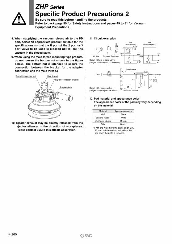
8. When supplying the vacuum release air to the PD port, select an appropriate product suitable for the specifications so that the R port of the 2 port or 3 port valve to be used is blocked not to leak the vacuum in the closed state.
9. When using the male thread mounting type product, do not loosen the bottom nut shown in the figure below. (The bottom nut is intended to secure the connection between the bracket for the adapter connection and the male thread.)
10. Ejector exhaust may be directly released from the ejector silencer in the direction of workpieces. Please contact SMC if this affects adsorption.
ZHP Series
Specific Product Precautions 2Be sure to read this before handling the products.Refer to back page 50 for Safety Instructions and pages 49 to 51 for Vacuum Equipment Precautions.
11. Circuit examples
12. Pad material and appearance colorThe appearance color of the pad may vary depending on the material.
Material Appearance color
NBR Black
Silicone rubber White
Urethane rubber Brown
FKM Black*
* FKM and NBR have the same color. But, “F” mark is indicated on the inside of the pad when the plate is removed.
260A