Vacuum Pad Equipped with Vacuum Generator Vacuum Pen Air ... · Air Pincette (Vacuum Pen) Air...
28
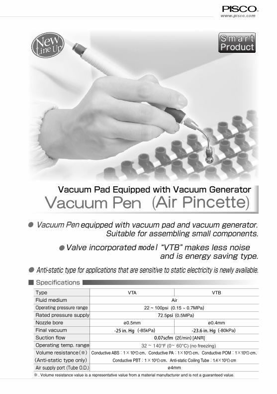
www.pisco.com ■ Specifications Smart Product Vacuum Pad Equipped with Vacuum Generator Vacuum Pen (Air Pincette) ● equipped with vacuum pad and vacuum generator. Suitable for assembling small components. ● Valve incorporated model “VTB” makes less noise and is energy saving type. ● Anti-static type for applications that are sensitive to static electricity is newly available. Type Fluid medium Operating pressure range Rated pressure supply Nozzle bore Final vacuum Suction flow Operating temp. range Volume resistance(※) (Anti-static type only) Air supply port (Tube O.D.) VTA VTB Air 22 ~ 100psi (0.15 ~ 0.7MPa) 72.5psi (0.5MPa) ø0.5mm ø0.4mm (-85kPa) (-80kPa) 0.07scfm (2ℓ/min) [ANR] Conductive ABS:1 ×10 4 Ω·cm、Conductive PA:1×10 3 Ω·cm、Conductive POM:1×10 2 Ω·cm、 Conductive PBT:1 ×10 3 Ω·cm、Anti-static Coiling Tube:1.4×10 3 Ω·cm ø4mm ※. Volume resistance value is a representative value from a material manufacturer and is not a guaranteed value. Vacuum Pen -25 in. Hg -23.6 in. Hg 32 ~ 140°F (0~ 60°C) (no freezing)
Transcript of Vacuum Pad Equipped with Vacuum Generator Vacuum Pen Air ... · Air Pincette (Vacuum Pen) Air...
www.pisco.com
Specifications
Sm a r tProduct
Vacuum Pad Equipped with Vacuum Generator
Vacuum Pen (Air Pincette) equipped with vacuum pad and vacuum generator.
Suitable for assembling small components.
Valve incorporated model “VTB” makes less noiseand is energy saving type.
Anti-static type for applications that are sensitive to static electricity is newly available.
TypeFluid mediumOperating pressure rangeRated pressure supplyNozzle boreFinal vacuumSuction flowOperating temp. rangeVolume resistance(※)
(Anti-static type only)Air supply port (Tube O.D.)
VTA VTB
Air
22 ~ 100psi (0.15 ~ 0.7MPa)72.5psi (0.5MPa)
ø0.5mm ø0.4mm
(-85kPa) (-80kPa)0.07scfm (2ℓ/min) [ANR]
Conductive ABS:1×10⁴Ω·cm、Conductive PA:1×10³Ω·cm、Conductive POM:1×10²Ω·cm、Conductive PBT:1×10³Ω·cm、Anti-static Coiling Tube:1.4×10³Ω·cm
ø4mm
※ . Volume resistance value is a representative value from a material manufacturer and is not a guaranteed value.
Vacuum Pen
-25 in. Hg -23.6 in. Hg
32 ~ 140°F (0~ 60°C) (no freezing)

Air Pincette
Vacuum Pen
VT B
Air Pincette(Vacuum Pen)
④. SET : Package set (Only when ordering Package set)
③. Type of pad tip holder
W
③Type of pad tip holder
SET
④Package set
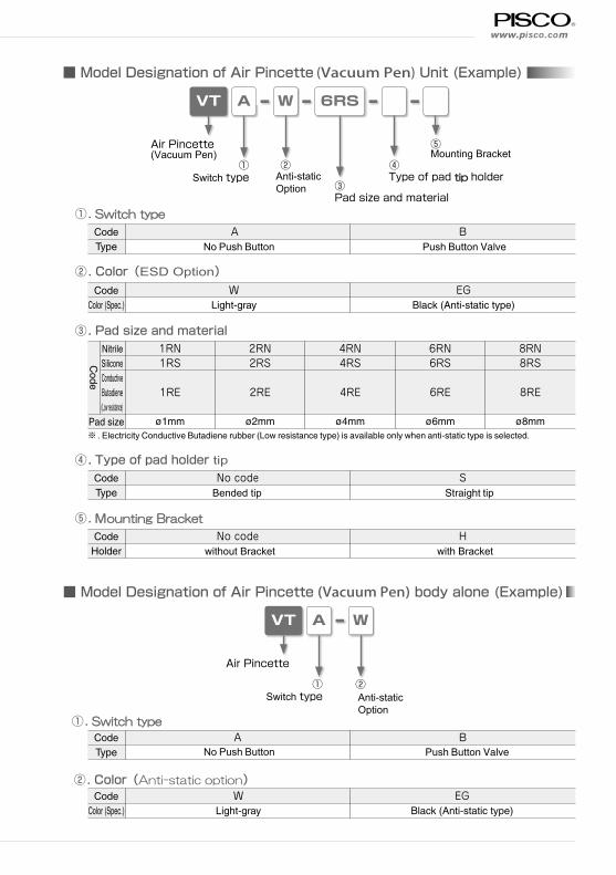
Model Designation of Air Pincette (Vacuum Pen) Package (Example)
Item
Air pincette
Pad tip holder
Vacuum pad(ø2, ø4, ø6, ø8mm)
Coiling tube
A package set includes:Quantity
1
1
1
1pc. per each size(Total 4pcs)
1
Details
VTA standard type. Color : Light-gray
VTA anti-static type. Color : Black
VTB standard type. Color : Light-gray
VTB anti-static type. Color : Black
Bended type for ø2 and ø4mm.Straight type for ø2 and ø4mmBended type for ø6 and ø8mm.Straight type for ø6 and ø8mmMaterial: Silicone rubber. Color: Translucent. For Standard type. Material: Conductive Butadiene rubber (Low resistance type). Color: Black. For anti-static type.
Tube color: Milk white. For Light-gray air pincette.
Tube color: Black. For Black (anti-static) air pincette.
CodeType
A
No codeBended tip
CodeColor(Spec.)
WLight-gray
B
SStraight tip
EGBlack (Anti-static type)
CodeType
①. Operation type
①Operation type
②Anti-staticOption
②. Color(ESD Option)
No Push Button Push Button Valve
www.pisco.com
③. Pad size and material
④. Type of pad holder tip
⑤. Mounting Bracket
VT
VT
A
A
①Switch type
Air Pincette(Vacuum Pen)
Air Pincette
①. Switch type
W
W
②Anti-staticOption
②
6RS
④Type of pad tip holder
③Pad size and material
⑤Mounting Bracket
Model Designation of Air Pincette (Vacuum Pen) Unit (Example)
Model Designation of Air Pincette (Vacuum Pen) body alone (Example)
NitrileSiliconeConductive Butadiene (Low resistance)
Pad size※ . Electricity Conductive Butadiene rubber (Low resistance type) is available only when anti-static type is selected.
1RN1RS
1RE
ø1mm
CodeType
CodeHolder
No codeBended tip
No codewithout Bracket
SStraight tip
Hwith Bracket
CodeType
CodeType
ANo Push Button
A
CodeColor (Spec.)
CodeColor (Spec.)
BPush Button Valve
B
4RN4RS
4RE
ø4mm
6RN6RS
6RE
ø6mm
8RN8RS
8RE
ø8mm
Code
2RN2RS
2RE
ø2mm
WLight-gray
WLight-gray
EGBlack (Anti-static type)
EGBlack (Anti-static type)
②. Color(Anti-static option)
①. Switch type
No Push Button Push Button Valve
①Switch type
②. Color(ESD Option)
Anti-staticOption

Air Pincette
Vacuum Pen
⑨
③
⑨
④
⑦⑥
⑧
Construction ( No Push Button Valve: VTA)
②①
⑤
⑱
⑯⑰
Construction ( Push Button Valve: VTB)
⑦①②②
⑥③④ ⑤
②
⑮⑭⑬
⑧
⑩⑪⑫
No. Parts nameMaterial
Standard type Anti-static type① Resin body A ABS Conductive ABS resin② Resin body B PA Conductive PA resin③ Resin body C POM Conductive POM resin④ Nozzle Assʼy ー⑤ Cover ABS Conductive ABS resin⑥ Diffuser Nickel-plated brass⑦ Filter element PVF⑧ Pad holder Nickel-plated brass⑨ Vacuum pad Nitrile rubber or Silicone rubber Conductive Butadiene rubber (Low resistance type)
No. Parts nameMaterial
Standard type Anti-static type① Resin pad holder ABS Conductive ABS resin② O-ring NBR③ O-ring support Nickel-plated brass④ Push button ABS Conductive ABS resin⑤ Resin body A PBT Conductive PBT resin⑥ Diffuser Nickel-plated brass⑦ Resin body B PA Conductive PA resin⑧ Fitting body PBT Conductive PBT resin⑨ Silencer element PVF⑩ Pipe Nickel-plated brass⑪ Nozzle Nickel-plated brass⑫ Spring Stainless steel⑬ Valve guide Nickel-plated brass⑭ Valve Nickel-plated brass⑮ Valve ring Nickel-plated brass⑯ Filter element PVF⑰ Pad holder Nickel-plated brass⑱ Vacuum pad Nitrile rubber or Silicone rubber Conductive Butadiene rubber (Low resistance type)

www.pisco.com
Characteristics
0
13
26
40
53
66
80
93
0.1 0.2 0.3 0.4 0.5 0.6 0.7
Supply pressure (MPa)
Fin
al v
acuu
m (
-kP
a)
Flo
w r
ate
(l/m
in[A
NR
])
VTB
Fina
l vac
uum
Suction flow
Air consu
mption
00 0.1 0.2 0.3 0.4 0.5 0.6 0.70
2
4
6
8
10
13
26
40
53
66
80
93
Supply pressure (MPa)
Fin
al v
acuu
m (
-kP
a)
Flo
w r
ate
(l/m
in[A
NR
])
VTA
Fina
l vac
uum
Suction flow
Air consumption
5
10
15
20
How to useAir Pincette with no Push Button Valve: VTA
Work-piece will be sucked by vacuum pad, while blocking the side hole during the supply of the compressed air 72.5psi (0.5MPa). Work-piece will be released by
unblocking the side hole.
Air Pincette with Push Button Valve: VTB Work-piece will be sucked by vacuum pad, while pressing
the push button during the supply of the compressed air
72.5psi (0.5MPa). Work-piece will be released by releasing
the button.
1. Do not use machine to operate the push button. The button may be damaged.
2. Carry out the maintenance of the filter element periodically. The element is replaceable by detaching
the ejector of VTA or the holder of VTB. There is a possibility of dropping the performance by the filter
clogging.
3. Silencer element of VTB is not replaceable.
4. Use coiling tube for Air Pincette in order to minimize the load on Fitting.
Detailed Safety InstructionBefore using PISCO products, be sure to read “Safety Instructions” and “Common Safety Instructions for Products Listed in This Catalog and “Common Safety Instructions for Vacuum Pad”.
Caution

Air Pincette
Vacuum Pen
VTA
10.9
B
9.8F
A ø13.
5ø4
7.8
ød
R13V
P
EX
Air Pincette (Vacuum Pen) with no Push Button Valve
VTB
VFUH
B
ød
min
. 14.
4m
ax. 1
5 ø4ø1
3
7.8
FA 11 9.8
R13V
P
EX
ø10
2-M3 screw hole
10
2533
2
12
8.313
Air Pincette (Vacuum Pen) with Push Button Valve
Mounting Bracket
compliant
compliant
compliant
Unit:mm
Model codePad O.D.
ødA B F
Weight(g)
CADfile name
VTA-2-1R3-4-5 1 8 184.4 64.4 22 VTA-_-1R_-(S-)_
VTA-2-2R3-4-5 2 8 183.4 63.4 22 VTA-_-2R_-(S-)_
VTA-2-4R3-4-5 4 8 183.7 63.7 22 VTA-_-4R_-(S-)_
VTA-2-6R3-4-5 6 11 190.8 70.8 23 VTA-_-6R_-(S-)_
VTA-2-8R3-4-5 8 9.5 189.3 69.3 23 VTA-_-8R_-(S-)_
※2:Replaced with Color (Spec.) code. Refer to page 920 for details.※3:Replaced with Pad rubber material code. Refer to page 920 for details.※4:Replaced with Type of pad holder code. Refer to page 920 for details.※5:Replaced with “H” for a body fixing holder. Refer the drawing below for the detailed dimension of a holder.
Unit:mm
Model codePad O.D.
ødA B F
Weight(g)
CADfile name
VTB-2-1R3-4-5 1 8 171.4 59.8 16 VTB-_-1R_-(S-)_
VTB-2-2R3-4-5 2 8 170.4 58.8 16 VTB-_-2R_-(S-)_
VTB-2-4R3-4-5 4 8 170.7 59.1 16 VTB-_-4R_-(S-)_
VTB-2-6R3-4-5 6 11 177.8 66.2 17 VTB-_-6R_-(S-)_
VTB-2-8R3-4-5 8 9.5 176.3 64.7 17 VTB-_-8R_-(S-)_
※2:Replaced with Color (Spec.) code. Refer to page 920 for details.※3:Replaced with Pad rubber material code. Refer to page 920 for details.※4:Replaced with Type of pad holder code. Refer to page 920 for details.※5:Replaced with “H” for a body fixing holder. Refer the drawing below for the detailed dimension of a holder.
Unit:mm
Model codeWeight
(g)
VFUH010P01 1.2
※Color : Light-gray only.

www.pisco.com
VTA Air Pincette (Vacuum Pen) Package with no Push Button Valve
VTB Air Pincette (Vacuum Pen) Package with Push Button Valve
compliant
compliant
Model code:VTA-2-SET
Model code:VTB-2-3-SET
Air Pincette Package includes :Item Quantity Details
Air pincette 1VTA standard type. Color : Light-grayVTA standard type. Color : BlueVTA anti-static type. Color : Black
Pad holder for ø2 and ø4mm
1R type for ø2 and ø4mm.Straight type for ø2 and ø4mm
Pad holder for ø6 and ø8mm
1R type for ø6 and ø8mm.Straight type for ø6 and ø8mm
Vacuum pad(ø2, ø4, ø6, ø8mm)
1pc. per each size
(Total 4pcs)Material: Silicone rubber. Color: Translucent. For Standard type. Material: Conductive Butadiene rubber (Low resistance type). Color: Black. For anti-static type.
Coiling tube 1Tube color: Milk white. For Light-gray air pincette.Tube color: Clear blue. For Blue air pincette.Tube color: Black. For Black (anti-static) air pincette.
Air Pincette Package includes :Item Quantity Details
Air pincette 1VTA standard type. Color : Light-grayVTA anti-static type. Color : Black
Pad holder for ø2 and ø4mm
1R type for ø2 and ø4mm.Straight type for ø2 and ø4mm
Pad holder for ø6 and ø8mm
1R type for ø6 and ø8mm.Straight type for ø6 and ø8mm
Vacuum pad(ø2, ø4, ø6, ø8mm)
1pc. per each size
(Total 4pcs)Material: Silicone rubber. Color: Translucent. For Standard type. Material: Conductive Butadiene rubber (Low resistance type). Color: Black. For anti-static type.
Coiling tube 1Tube color: Milk white. For Light-gray air pincette.Tube color: Black. For Black (anti-static) air pincette.

Air Pincette
Vacuum Pen
UL Coiling Tube for Air Pincette
ø24
ø4
100128
328 (max 520)
100
Replacement of Element: VTA Replacement of Element: VTB
Filter element
Filter element
Unit:mm
Model codeWeight
(g)Applicable Air Pincette unit
UL04-2-W 15 VTA-W-3, VTB-W-315UEL04-2-B VTA-EG-3, VTB-EG-3
Applicable Pad sizeModel CodeBended Pad Holder Tip
VPZ-2VPZ-6
ø1, ø2, ø4mmø6, ø8mm
Replacement of Pad Holder Tip
Bended Tip
Straight Tip
Applicable Pad sizeModel CodeStraight Pad Holder Tip
VPZ-2-SVPZ-6-S
ø1, ø2, ø4mmø6, ø8mm
VPZ-2
VPZ-6
VPZ-2-S
VPZ-6-S
Model codeVTVA
Model code
FEE10x2
Vacuum Pen
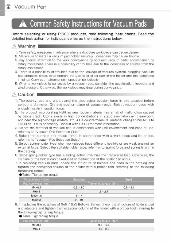
Common Safety Instructions for Vacuum Pads
Warning
Before selecting or using PISCO products, read following instructions. Read the detailed instruction for individual series as the instructions below.
1. Take safety measures in advance where a dropping work-piece can cause danger.2. Make sure to install a vacuum pad holder securely. Looseness may cause trouble.3. Pay special attention to the work conveyance by screwed vacuum pads, accompanied by
rotary movement. There is a possibility of troubles due to the looseness of screws from therotary movement.
4. There is a possibility of troubles due to the leakage of vacuum system, clogging, vacuumpad abrasion, crack, deterioration, the galling of slider part in the holder and the loosenessin joints. Carry out maintenance inspection periodically.
5. When a work-piece is conveyed by a vacuum pad, consider the acceleration, impacts andwind pressure. Otherwise, the work-piece may drop during conveyance.
Caution1. Thoroughly read and understand the theoretical suction force in this catalog before
selecting diameter, Qty and suction place of vacuum pads. Select vacuum pads withenough margin in suction force.
2. The product incorporating NBR as seal rubber material has a risk of malfunction causedby ozone crack. Ozone exists in high concentrations in static elimination air, clean-room,and near the high-voltage motors, etc. As a countermeasure, material change from NBR toHNBR or FKM is necessary. Consult with PISCO for more information.
3. Select the material of vacuum pad in accordance with use environment and ease of use,referring to “Vacuum Pad Selection Guide” .
4. Select the suitable pad shape (type) in accordance with a work-piece and its shape,referring to “Vacuum Pad Selection Guide” .
5. Select spring-holder type when work-pieces have different heights or are weak against anexternal force. Select the suitable holder type, referring to spring force and spring length inthe catalog.
6. Since spring-holder type has a sliding action, minimize the transverse load. Otherwise, thelife time of the holder can be reduced or malfunction of the holder can occur.
7. In replacing vacuum pads, check the structure of holders and pads in the catalog andtighten the hexagonal-column of the holder with a proper tool, referring to the followingtightening torque.Table. Tightening torque
Vacuum pad holder Standard SmallPad screw size() Tightening torque(N·m)
M4×0.7 0.5 ~ 1.0 0.9 ~ 1.1M6×1 2 ~ 2.7
M10×1.5 5 ~ 7 –M20×2 9 ~ 10 –
8. In replacing the adapters of Soft / Soft Bellows Series, check the structure of holders, padand adapters and tighten the hexagonal-column of the holder with a proper tool, referring tothe following tightening torque.Table. Tightening torque
Pad screw size() Tightening torque(N·m)M4×0.7 0.7 ~ 0.8M6×1 1.5 ~ 2.0
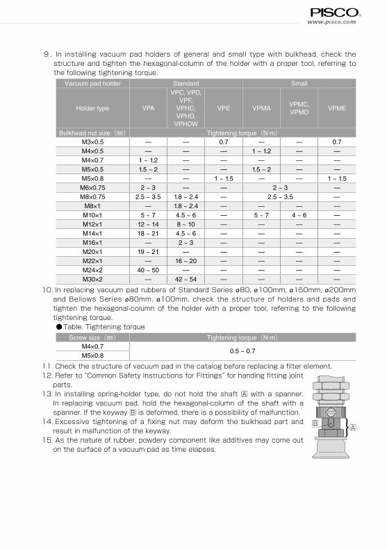
9 . In installing vacuum pad holders of general and small type with bulkhead, check the structure and tighten the hexagonal-column of the holder with a proper tool, referring to the following tightening torque.
Vacuum pad holder Standard Small
Holder type VPA
VPC, VPD,VPF,
VPHC,VPHD,
VPHDW
VPE VPMAVPMC,VPMD
VPME
Bulkhead nut size() Tightening torque(N·m)M3×0.5 — — 0.7 — — 0.7M4×0.5 — — — 1 ~ 1.2 — —M4×0.7 1 ~ 1.2 — — — — —M5×0.5 1.5 ~ 2 — — 1.5 ~ 2 — —M5×0.8 — — 1 ~ 1.5 — — 1 ~ 1.5
M6×0.75 2 ~ 3 — — 2 ~ 3 —M8×0.75 2.5 ~ 3.5 1.8 ~ 2.4 — 2.5 ~ 3.5 —
M8×1 — 1.8 ~ 2.4 — — — —M10×1 5 ~ 7 4.5 ~ 6 — 5 ~ 7 4 ~ 6 —M12×1 12 ~ 14 8 ~ 10 — — — —M14×1 18 ~ 21 4.5 ~ 6 — — — —M16×1 — 2 ~ 3 — — — —M20×1 19 ~ 21 — — — — —M22×1 — 16 ~ 20 — — — —M24×2 40 ~ 50 — — — — —M30×2 — 42 ~ 54 — — — —
10. In replacing vacuum pad rubbers of Standard Series ø80, ø100mm, ø150mm, ø200mmand Bellows Series ø80mm, ø100mm, check the structure of holders and pads andtighten the hexagonal-column of the holder with a proper tool, referring to the followingtightening torque.Table. Tightening torque
Screw size() Tightening torque(N·m)M4×0.7
0.5 ~ 0.7M5×0.8
11.12.
13.
14.
15.
Check the structure of vacuum pad in the catalog before replacing a filter element. Refer to “Common Safety Instructions for Fittings” for handing fitting joint
parts. In installing spring-holder type, do not hold the shaft A with a spanner.
In replacing vacuum pad, hold the hexagonal-column of the shaft with aspanner. If the keyway B is deformed, there is a possibility of malfunction. Excessive tightening of a fixing nut may deform the bulkhead part and Bresult in malfunction of the keyway. As the nature of rubber, powdery component like additives may come out
on the surface of a vacuum pad as time elapses.
A}
www.pisco.com
Vacuum Pen
0
4
2
0
10
18
16
14
12
8
6
20
20 40 60 80 100
ø15
ø10
ø6
ø8
Vacuum level(–kPa)
The
oret
ical
suc
tion
forc
e(N)
Pad
dia
.(m
m)
ø4ø3ø2
0
500
0
1000
2000
3500
3000
1500
2500
20 40 60 80 100
ø200
ø150
ø100
ø80
ø60
Vacuum level(–kPa)
The
oret
ical
suc
tion
forc
e(N)
Pad
dia
.(m
m)
0
100
50
0
150
200
250
20 40 60 80 100
ø50
ø40
ø30
ø25
ø20
Vacuum level(–kPa)
The
oret
ical
suc
tion
forc
e(N)
Pad
dia
.(m
m)
Pad dia.:ø2mm ~ ø15mm Pad dia.:ø20mm ~ ø50mm
Pad dia.:ø60mm ~ ø200mm
0
0.2
0
0.4
0.8
1.4
1.2
0.6
1.0
20 40 60 80 100
ø3
ø4
ø2
ø1.5
ø1ø0.7
Vacuum level(–kPa)
The
oret
ical
suc
tion
forc
e(N)
Pad
dia
.(m
m)
Pad dia.(small):ø0.7mm ~ ø4mm
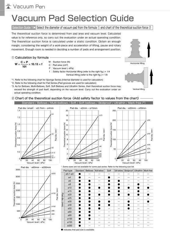
Vacuum Pad Selection GuideSelection Guide 1
Select the diameter of vacuum pad from the formula ① and chart of the theoretical suction force ②The theoretical suction force is determined from pad area and vacuum level. Calculated value is for reference only, so carry out the evaluation under an actual operating condition. The theoretical suction force is calculated under a static condition. Obtain an enough margin, considering the weight of a work-piece and acceleration of lifting, pause and rotary movement. Enough room is needed in deciding a number of pads and arrangement position.
① Calculation by formula
W = C × P
× 10.13 × f−101
*1. Refer to the following chart for Sponge Series.(Internal diameter is used for calculation)*2. Refer to the following chart for Flat Series.(Pad grooves are used for calculation)*3. As for Bellows, Multi-Bellows, Soft, Soft Bellows and Ultrathin Series, their theoretical suction force may
exceed the strength of pad itself, depending on the vacuum level. Carry out the evaluation under anactual operating condition.
Horizontal lifting
Vertical lifting
W :Suction force (N)C : Pad area (cm²)P : Vacuum level (−kPa)f : Safety factor Horizontal lifting (refer to the right fig.)
1/4Vertical lifting (refer to the right fig.)
1/8
② Chart of the theoretical suction force〈Add safety factor to values from the chart〉Standard / Bellows / Multi-bellows / Soft / Soft bellows / Skidproof / Ultrathin / Mark-free (*)
*. Some sizes are not available for some pad series. Refer to the following size list.
Pad type Standard Bellows Multi-bellows Soft Soft bellows Skidproof Ultrathin Mark-free
Pad dia. (m
m)
ø0.7~ø3 ー ー ー ー ー ー ーø4 ー ー ー ー ー ーø6 ー ー ー ーø8 ー ー ーø10 ø15 ー ー ーø20 ø25 ー ー ー ー ー ーø30 ー ー ø40 ー ー ーø50 ー ー ー ーø60 ー ー ー ー ー ーø80 ー ー ー ー ー ーø100 ー ー ー ー ー ーø150 ー ー ー ー ー ー ーø200 ー ー ー ー ー ー ー
indicates that pad size is available.

0
300
250
200
150
100
50
0
350
400
450
20 40 60 80 100
ø100
ø50
ø70
ø10ø15ø20
ø30 ø25ø35
Vacuum level(–kPa)
The
oret
ical
suc
tion
forc
e(N)
Pad
dia
.(m
m)
パッド径:ø10mm ~ ø100mm
0
8
4
0
12
16
20
6
2
10
14
18
20 40 60 80 100
ø30
ø25
ø20
ø15
ø10
Vacuum level(–kPa)
The
oret
ical
suc
tion
forc
e(N)
Pad
dia
.(m
m)
0
15
10
5
0
25
20
20 40 60 80 100
8×30
6×30
5×30,8×20
4×306×20
5×20
4×20
6×10
Vacuum level(–kPa)
The
oret
ical
suc
tion
forc
e(N)
Pad
siz
e(m
m)
4×103.5×7
2×4
Pad size:2×4mm, 3.5×7mm,×10mm, ×20mm, ×30mm
5×10
Sponge pad Flat pad Oval padPad dia.:ø10mm ~ ø30mmPad dia.:ø10mm ~ ø100mm Pad size:2×4mm ~ 8×30mm

Vacuum Pad
ød
øS
Selection Guide 2
Select a vacuum pad type according to a work-piecePlease select suitable pads for your application from the following.
Standard Series Bellows / Multi-bellows Series
Ultrathin Series
Skidproof Series
Thick & flat work-piece Round fruit or ball (*1)
Oval Series
Soft / Soft bellows Series
Food package
Long work-piece (e.g. circuit board and semiconductor product)
Molded parts / Fragile work-piece Greasy work-piece such as pressed parts
Thin work-piece such as paper or plastic bag
General type
Deep type
*1. The table below is a reference for the vacuum pad deep type and the size of round work-piece.
Spherical dia:S() ø20 ø30 ø40 ø50 ø80 ø100 ø120 ø160 ø200
Pad dia.:d() ø15 ø20 ø25 ø30 ø40 ø50 ø60 ø80 ø100
*2. Refer to the previous page for pad dia. selection except deep type. Refer to thenext page for the characteristics of pad materials.
Sponge Series
Exterior wall panel, pebble, seashell
Mark-free Series
Flat Series
LCD glass / in Painting process / semiconductor
Thin work-piece such as sheet or plastic bag
Small work-piece or semiconductor product
Small type
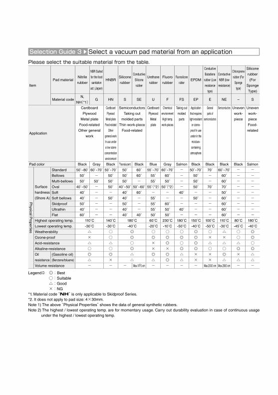
Selection Guide 3
Select a vacuum pad material from an applicationPlease select the suitable material from the table.
Legend :Best:Suitable:Good×:NG
*1. Material code “NH” is only applicable to Skidproof Series.*2. It does not apply to pad size: 4×30mm.Note 1) The above “Physical Properties” shows the data of general synthetic rubbers.Note 2) The highest / lowest operating temp. are for momentary usage. Carry out durability evaluation in case of continuous usage
under the highest / lowest operating temp.
Item
Pad materialNitrile
rubber
NBR Suited
for the food
sanitation
act. (Japan)
HNBRSilicone
rubber
Conductive
Silicone
rubber
Urethane
rubber
Fluoro
rubber
Fluorosilicone
rubberEPDM
Conductive
Butadiene
rubber (Low
resistance
type)
Conductive
NBR (low
resistance)
Chloroprene
rubber (For
Sponge
type)
Silicone
rubber
(For
Sponge
Type)
Material codeN,
NH(*1)G HN S SE U F FS EP E NE – S
Application
Cardboard
Plywood
Metal plate
Food-related
Other general
work
Cardboard
Plywood
Metal plate
Food-related
Other
general work
In use under
a low ozone
concentration
environment
Semiconductors
Taking out
molded parts
Thin work-piece
Food-related
Cardboard
Plywood
Metal
plate
Chemical
environment
High temp.
work-pieces
Taking out
molded
parts
Application
that requires
light-resistant
or ozone-
proof In use
under in the
moisture-
containing
atmosphere
General
parts of
semiconductors
Semiconductors Uneven
work-
piece
Uneven
work-
piece
Food-
related
Pad color Black Gray Black Translucent Black Blue Gray Salmon Black Black Black Black Salmon
Physical P
roperties
Surface
hardness
(Shore A)
Standard 50˚~80˚ 60˚~70˚ 50˚~70˚ 50˚ 60˚ 55˚~70˚ 60˚~70˚ - 50˚~70˚ 70˚ 60˚~70˚ - -Bellows 50˚ - 50˚ 50˚ 60˚ 55˚ 60˚ - 50˚ - 60˚ - -Multi-bellows 50˚ 50˚ 50˚ 50˚ - 55˚ 50˚ - 50˚ - 60˚ - -Oval 40˚~50˚ - 50˚ 40˚~50˚ 50˚~60˚ 55(*2)50(*2) - 50˚ 70˚ 70˚ - -Soft 40˚ - - 40˚ 60˚ - - 40˚ - - 50˚ - -Soft bellows 40˚ - 50˚ 40˚ - 55˚ - - 50˚ - 60˚ - -Skidproof 50˚ - - 50˚ - 55˚ 60˚ - - - 60˚ - -Ultrathin 40˚ - - 40˚ - 55˚ 50˚ 40˚ - - 60˚ - -Flat 60˚ - - 40˚ 40˚ 50˚ 50˚ - - - 60˚ - -
Highest operating temp. 110˚C 140˚C 180˚C 60˚C 230˚C 180˚C 150˚C 100˚C 110˚C 80˚C 180˚C
Lowest operating temp. -30˚C -30˚C -40˚C -20˚C -10˚C -50˚C -40˚C -50˚C -30˚C -45˚C -40˚C
Weatherability Ozone-proof × × × Acid-resistance × Alkaline-resistance × × Oil
resistance
(Gasoline oil) × × × (Benzene/toluene) × × ×
Volume resistance - - - Max.105Ω·cm - - - - Max.200Ω·cm Max.200Ω·cm - -

Vacuum Pad
To prevent dust from getting into the pad holder.Install a vacuum filter pad direct mounting type between a vacuum pad and a holder.
Work-piece
Vacuum air containing dust.
Vacuum air from which dust was removed by a vacuum filter.
Vacuum pad
Pad holder
Vacuum filterpad direct mounting type
Vacuum generator
To operate several vacuum pads by single vacuum source.Installing a fall prevention valve between a vacuum pad and a holder prevents the troubles like system break down, minimizing the vacuum drop of the whole system automatically by reducing suction flow of the part where the work-piece falls from the vacuum pad (within the range not causing any problem), or no work-piece is to be sucked.
Fall prevention valve
Pad holder
Vacuum pad Work-piece
Please select the suitable vacuum pad resin material from the table.
Legend :Best:Suitable:Good×:NG
Note 1) The above “Physical Properties” shows the data of pad resin material only. The holder of Mark-free Series is not included.Note 2) The above “Physical Properties” shows the data of resin attachment only. The pad rubber is not included.Note 3) The above “Physical Properties” shows general properties of resin materials and not a guaranteed value. Carry out the
necessary evaluation under an actual operating condition.Note 4) The highest / lowest operating temp. is for momentary usage. Carry out durability evaluation in case of continuous usage
under the highest / lowest operating temp.Note 5) Volume resistance is a representative value from the material manufacture, and not a guaranteed value.
Item
Pad material PEEK POM Conductive PEEK
Material code
Mark free series K M KE
Resin attachment for Bellows series -QK -QM -QKE
Application
Semiconductor/
Manufacturing machine for
liquid crystal
General production line
Food-related machine
Packaging machine
Semiconductors/
Manufacturing machine for
liquid crystal
Electronic components
Pad color Natural (ivory) White Black
Physical P
roperties
Highest operating temp. 250˚C 95˚C 250˚C
Lowest operating temp. -50˚C -60˚C -50˚C
Weatherability × Acid-resistance × Alkaline-resistance Self-lubricity Abrasion-resistance Volume resistance - - 105~106Ω·cm
× ×
Vacuum source

15°
Reference Guide for Vacuum PadImpact on pad
Avoid an impact or a large force on a vacuum pad, when it is pressed against a work-piece. It may cause deformation, crack or abrasion at an early stage of use. Adjust the pad position so that the lip of pad touches lightly on a work-piece. Especially a small type of vacuum pad should be positioned precisely.
Porous or perforated work-pieceSince the suction of a porous work-piece causes a drop of suction force, select the proper specifications of vacuum system and secure a larger effective cross-section area of the piping. Selecting a small type of vacuum pad is one of solutions to reduce the air leakage.
Large and wide flat plate work-pieceWhen lifting large size of glass board or circuit board, work-piece may bend by the lifting acceleration or the self-weight. Select a proper size of pad and positioning, considering an enough margin of suction force.
Soft work-piece Work-piece with different heightsSelect Long Stroke Series for work-pieces having different heights, or piled-up work-pieces. Its stroke can absorb the difference in height.
Inclined work-pieceSelect Free Holder for an inclined work-piece.
Positioning within this range
Porous work-piece
Plastic bag, paper, etc.
Large size of glass board or circuit board
Inclined work-piece
Work-pieces having different heights
Large force by lifting
Plastic bag, paper bag
Figure-1 Figure-2
Long Stroke Series
Free holderTwo selection of articulation angle: 0-15°/0-30°
Lifting work-piece, sucking the both side of itSince all vacuum pad holders are designed for horizontal lifting, consider the strength of holders and pads.
Work-piece
Lifting
Consider to reduce the stress against holders and pads by sucking the both sides of work-piece.
Vacuum pad
Pad holder
Conveyance with rotary movementWhen vacuum pad is fixed with a screw and has a rotary movement, the pad may drop due to the loosened screw. Pay special attention when the vacuum location of work-piece is off the center of work-piece gravity.
Safety factor (1/8) of vertical lifting needs to be applied in rotary conveys or lateral movement
When soft work-pieces such as plastic bags, papers or thin boards are sucked, work-pieces can be deformed or shrunk by vacuum suction (Figure-1). Select smaller vacuum pads and reduce the vacuum pressure. Smaller vacuum pads are suitable for plastic bags and papers. When plastic / paper bags are opened by using vacuum pads, shift the center of two vacuum pads slightly in order to open them easily as Figure-2 shows.
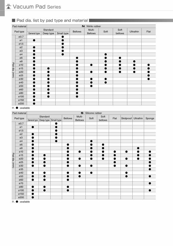
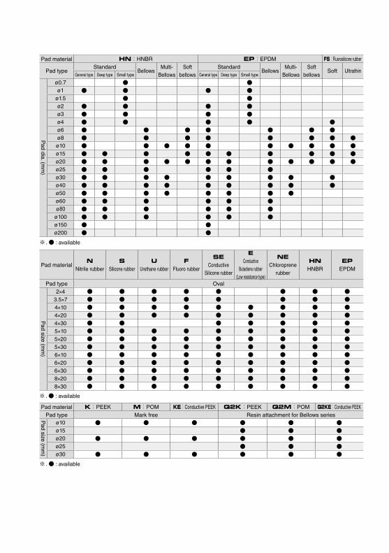
Pad dia. list by pad type and material
Vacuum Pad Series
Pad material N:Nitrile rubber
Pad typeStandard
BellowsMulti-
BellowsSoft
Soft bellows
Ultrathin FlatGeneral type Deep type Small type
Pad dia. (m
m)
ø0.7 ø1
ø1.5 ø2 ø3 ø4 ø6 ø8 ø10 ø15 ø20 ø25 ø30 ø40 ø50 ø60 ø80 ø100 ø150 ø200
※ . : available
Pad material S:Silicone rubber
Pad typeStandard
BellowsMulti-
BellowsSoft
Soft bellows
Flat Skidproof Ultrathin SpongeGeneral type Deep type Small type
Pad dia. (m
m)
ø0.7 ø1
ø1.5 ø2 ø3 ø4 ø6 ø8 ø10 ø15 ø20 ø25 ø30 ø35 ø40 ø50 ø60 ø70 ø80 ø100 ø150 ø200
※ . : available

Pad material U:Urethane rubber
Pad typeStandard
BellowsMulti-
BellowsSoft
bellowsSkidproof Ultrathin Flat
General type Deep type Small type
Pad dia. (m
m)
ø0.7 ø1
ø1.5 ø2 ø3 ø4 ø6 ø8 ø10 ø15 ø20 ø25 ø30 ø40 ø50 ø60 ø80 ø100 ø150 ø200
※ . : available
Pad material F:Fluoro rubber G:NBR Suited for the food sanitation act. (Japan)
Pad typeStandard
BellowsMulti-
BellowsSkidproof Ultrathin Flat
Standard Multi-BellowsGeneral type Deep type Small type General type Deep type Small type
Pad dia. (m
m)
ø0.7 ø1
ø1.5 ø2 ø3 ø4 ø6 ø8 ø10 ø15 ø20 ø25 ø30 ø40 ø50 ø60 ø80 ø100 ø150 ø200
※ . : available
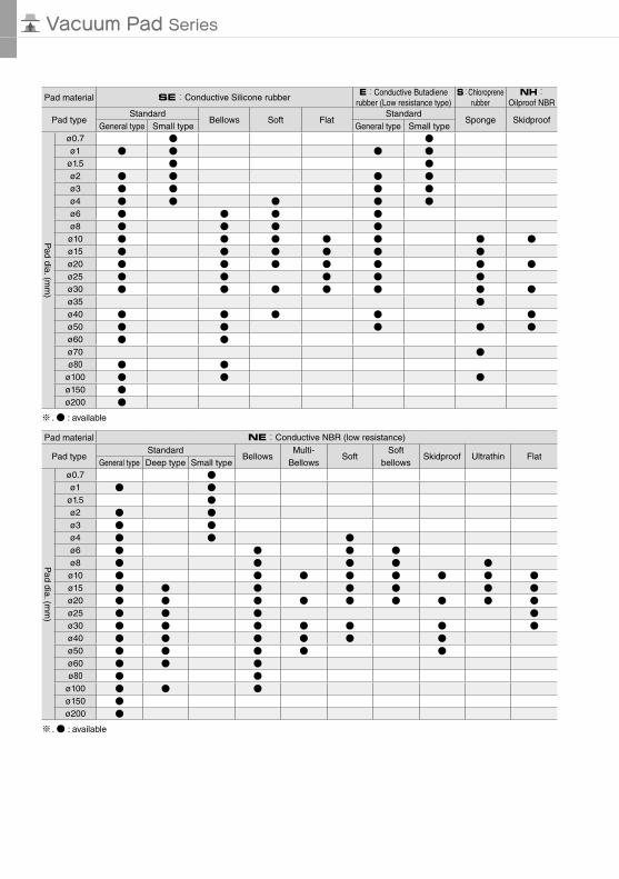
Vacuum Pad Series
Pad material SE:Conductive Silicone rubberE:Conductive Butadiene
rubber (Low resistance type)S:Chloroprene
rubberNH:
Oilproof NBR
Pad typeStandard
Bellows Soft FlatStandard
Sponge SkidproofGeneral type Small type General type Small type
Pad dia. (m
m)
ø0.7 ø1
ø1.5 ø2 ø3 ø4 ø6 ø8 ø10 ø15 ø20 ø25 ø30 ø35 ø40 ø50 ø60 ø70 ø80
ø100 ø150 ø200
※ . : available
Pad material NE:Conductive NBR (low resistance)
Pad typeStandard
BellowsMulti-
BellowsSoft
Soft bellows
Skidproof Ultrathin FlatGeneral type Deep type Small type
Pad dia. (m
m)
ø0.7 ø1
ø1.5 ø2 ø3 ø4 ø6 ø8 ø10 ø15 ø20 ø25 ø30 ø40 ø50 ø60 ø80
ø100 ø150 ø200
※ . : available
Pad material HN:HNBR EP:EPDM FS:Fluorosilicone rubber
Pad typeStandard
BellowsMulti-
BellowsSoft
bellowsStandard
BellowsMulti-
BellowsSoft
bellowsSoft Ultrathin
General type Deep type Small type General type Deep type Small type
Pad dia. (m
m)
ø0.7 ø1
ø1.5 ø2 ø3 ø4 ø6 ø8 ø10 ø15 ø20 ø25 ø30 ø40 ø50 ø60 ø80
ø100 ø150 ø200
※ . : available
Pad materialN
Nitrile rubberS
Silicone rubberU
Urethane rubberF
Fluoro rubber
SEConductive
Silicone rubber
EConductive
Butadiene rubber (Low resistance type)
NEChloroprene
rubber
HNHNBR
EPEPDM
Pad type Oval
Pad size (m
m)
2×4 3.5×7 4×10 4×20 4×30 5×10 5×20 5×30 6×10 6×20 6×30 8×20 8×30
※ . : available
Pad material K:PEEK M:POM KE:Conductive PEEK Q2K:PEEK Q2M:POM Q2KE:Conductive PEEKPad type Mark free Resin attachment for Bellows series
Pad size (m
m)
ø10 ø15 ø20 ø25 ø30
※ . : available
Vacuum Pad Series
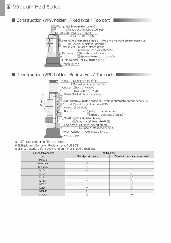
Construction (VPA holder : Fixed type / Top port)
Nut(aNickel-plated brass or Trivalent chromate carbon steel※3)
Pad holder(aNickel-plated brass)
Plain washer(Nickel-plated SPCC)
(bSpecial stainless steel※2)
(bSpecial stainless steel※2)
Vacuum pad
Pad screw(aNickel-plated brass)(bSpecial stainless steel※2)
Fitting(aNickel-plated brass)(bSpecial stainless steel※2)
Gasket(aSPCC + NBR)(bSUS316 + FKM)
Construction (VPC holder : Spring type / Top port)
Str
oke
Nut(aNickel-plated brass or Trivalent chromate carbon steel※3)(bSpecial stainless steel※2)
Bush(Nickel plated aluminum)
Plain washer(Nickel-plated SPCC)Vacuum pad
Pad screw(aNickel-plated brass)(bSpecial stainless steel※2)
Fitting(aNickel-plated brass)(bSpecial stainless steel※2)
Gasket(aSPCC + NBR)(bSUS316 + FKM)
Shaft(aNickel-plated brass)(bSpecial stainless steel※2)
Rotation stopper(aNickel-plated brass)(bSpecial stainless steel※2)
Spring(SUS304)
※ 3. Nut material differs depending on the bulkhead thread size.Bulkhead thread size
()Nut material
Nickel-plated brass Trivalent chromate carbon steelM5×0.5 ーM6×0.75 ーM8×0.75 ーM10×1 ーM12×1 ー M14×1 ー M16×1 ー M20×1 ー M22×1 ー M24×2 ーM30×2 ー
※ 1. a : Standard spec. b : “-S3” spec.※ 2. Equivalent Corrosion Resistance to SUS303
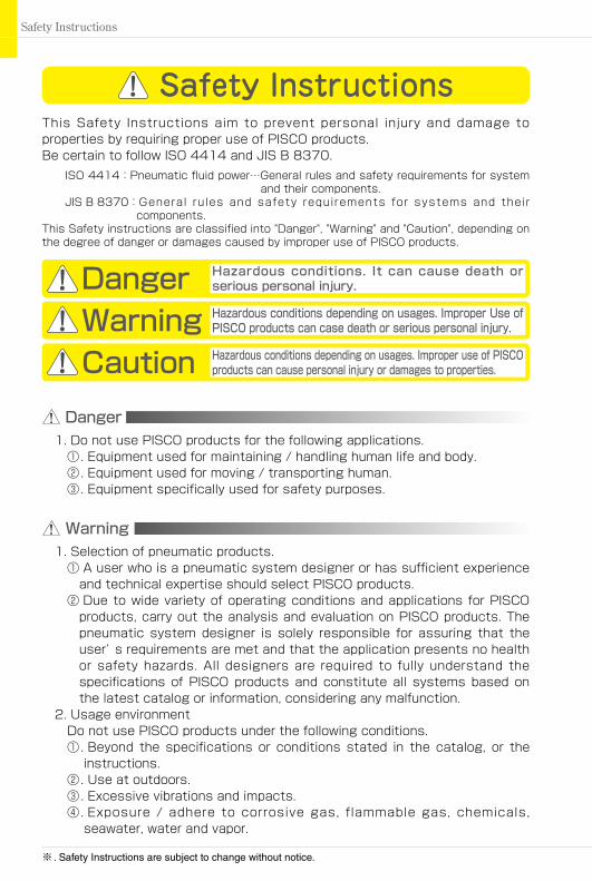
Safety Instructions
Warning
This Safety Instructions aim to prevent personal injury and damage to properties by requiring proper use of PISCO products.Be certain to follow ISO 4414 and JIS B 8370.
ISO 4414:Pneumatic fluid power…General rules and safety requirements for system and their components.
JIS B 8370: General rules and safety requirements for systems and their components.
This Safety instructions are classified into "Danger", "Warning" and "Caution", depending on the degree of danger or damages caused by improper use of PISCO products.
Safety Instructions
Danger Hazardous conditions. It can cause death orserious personal injury.
Warning Hazardous conditions depending on usages. Improper Use ofPISCO products can case death or serious personal injury.
Caution Hazardous conditions depending on usages. Improper use of PISCO products can cause personal injury or damages to properties.
※ . Safety Instructions are subject to change without notice.
1. Selection of pneumatic products.① A user who is a pneumatic system designer or has sufficient experience
and technical expertise should select PISCO products.② Due to wide variety of operating conditions and applications for PISCO
products, carry out the analysis and evaluation on PISCO products. Thepneumatic system designer is solely responsible for assuring that theuser’ s requirements are met and that the application presents no healthor safety hazards. All designers are required to fully understand thespecifications of PISCO products and constitute all systems based onthe latest catalog or information, considering any malfunction.
2. Usage environmentDo not use PISCO products under the following conditions.①. Beyond the specifications or conditions stated in the catalog, or the
instructions.②. Use at outdoors.③. Excessive vibrations and impacts.④. Exposure / adhere to corrosive gas, flammable gas, chemicals,
seawater, water and vapor.
Danger1. Do not use PISCO products for the following applications.
①. Equipment used for maintaining / handling human life and body.②. Equipment used for moving / transporting human.③. Equipment specifically used for safety purposes.

http://www.pisco.com
3. Handling of product①. The pneumatic equipments shall be handled by a person having
enough knowledge and experiences. Improper use of compressed air isdangerous. Assembly, operation and maintenance of machines usingpneumatic equipment should be conducted by a person with enoughknowledge and experience.
②. Do not operate machine / equipment or remove pneumatic equipmentuntil safety is confirmed.(1). Make sure that preventive measures against falling work-pieces or
sudden movements of machine are completed before inspection or maintenance of these machine.
(2). Make sure the above preventive measures are completed. A compressed air supply and the power supply to the machine must be off, and also the compressed air in the systems must be exhausted.
(3). Restart the machines with care after ensuring to take all preventive measures against sudden movements.
③. Do not disassemble or modify PISCO products, which affect theperformance, function, and basic structure of the product.
④. Take safety measures such as providing a protection cover if there is arisk of causing damages or fire on machine / facilities by a fluid leakage.
⑤. Do not touch the release-ring of push-in fitting when there is a workingpressure.
⑥. Frequent switchover of compressed air may generate heat, and there isa risk of causing burn injury.
⑦. Avoid any load on PISCO products, such as, a tensile strength, twistingand bending. Otherwise, there is a risk of causing damage to theproducts.
⑧. Do not use PISCO products for applications where threads or tubesswing / rotate. The product can be damaged in these applications.
⑨. Do not force the product to rotate or swing even its resin body isrotatable. It may cause damage to the product and a fluid leakage.
⑩. Do not supply excessively dry air to products. It may cause malfunctiondue to a deterioration of rubber parts.
⑪. Do not wash or paint products with water or solvent. Solvent maydamage a resin body, or painting may cause malfunction.
⑫. The product incorporating NBR as seal rubber material has arisk of malfunction caused by ozone crack. Ozone exists in highconcentrations in static elimination air, clean-room, and near the high-voltage motors, etc. As a countermeasure, material change from NBRto HNBR or FKM is necessary. Consult with PISCO for more information.
⑬. Do not stand on a product, or put anything on it. It may cause falls,personal injury or damage to the product.

45
真空発生器・真空ポンプ対応ユニット・真空パッド・真空関連機器SeriesIndexSafety Instructions
Safety Instructions
Warranty
Disclaimer
When the product produces a trouble, which is caused by our responsibility, we will carry out either one of the following measures immediately.①. Free-of-charge replacement of same product②. Free-of-charge repair of the product at our factory
1. PISCO does not take any responsibility for any incidental or indirect loss,such as production line stop, interruption of business, loss of benefits,personal injury, etc., caused by any failure on use or application of PISCOproducts.
2. When a cause of the trouble/malfunction applies to any of the followingitems, it is excluded from the coverage of the above warranty.①. A case by a natural disaster, a fire except our responsibility, the act by
the third person/party, the intention or fault of the customer.②. A case when a product is used out of the specific range or the method
listed in the product catalog or the instruction manual.③. A case by the remodeling of the product or by a change of structure,
performance, or specifications which PISCO does not involved in.④. A case by the event that is unpredictable by the evaluations and the
measures at the time on or before the initial delivery.⑤. A case caused by the phenomenon that is able to be evaded if your
machine or equipment has functions or structures that are comprised ina common sense when this product is incorporated in your machine orequipment.
3. T he damages caused by the defect of PISCO products shall be covered butlimited to the full amount of the PISCO products paid by the customer.Additionally, the above warranty is limited simply to the product itself. The damage induced by the trouble of the product will not be compensated.
http://www.pisco.com
46
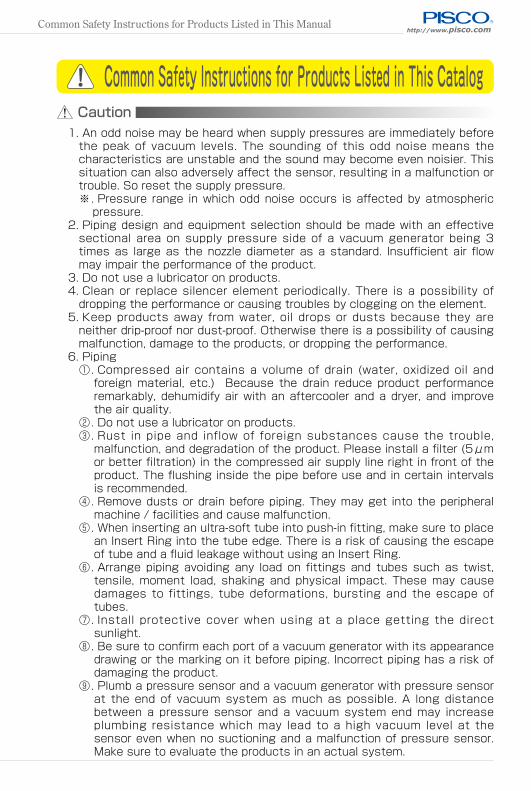
Caution1. An odd noise may be heard when supply pressures are immediately before
the peak of vacuum levels. The sounding of this odd noise means thecharacteristics are unstable and the sound may become even noisier. Thissituation can also adversely affect the sensor, resulting in a malfunction ortrouble. So reset the supply pressure.※. Pressure range in which odd noise occurs is affected by atmospheric
pressure.2. Piping design and equipment selection should be made with an effective
sectional area on supply pressure side of a vacuum generator being 3times as large as the nozzle diameter as a standard. Insufficient air flowmay impair the performance of the product.
3. Do not use a lubricator on products.4. Clean or replace silencer element periodically. There is a possibility of
dropping the performance or causing troubles by clogging on the element.5. Keep products away from water, oil drops or dusts because they are
neither drip-proof nor dust-proof. Otherwise there is a possibility of causingmalfunction, damage to the products, or dropping the performance.
6. Piping①. Compressed air contains a volume of drain (water, oxidized oil and
foreign material, etc.) Because the drain reduce product performanceremarkably, dehumidify air with an aftercooler and a dryer, and improvethe air quality.
②. Do not use a lubricator on products.③. Rust in pipe and inflow of foreign substances cause the trouble,
malfunction, and degradation of the product. Please install a filter (5μmor better filtration) in the compressed air supply line right in front of theproduct. The flushing inside the pipe before use and in certain intervalsis recommended.
④. Remove dusts or drain before piping. They may get into the peripheralmachine / facilities and cause malfunction.
⑤. When inserting an ultra-soft tube into push-in fitting, make sure to placean Insert Ring into the tube edge. There is a risk of causing the escapeof tube and a fluid leakage without using an Insert Ring.
⑥. Arrange piping avoiding any load on fittings and tubes such as twist,tensile, moment load, shaking and physical impact. These may causedamages to fittings, tube deformations, bursting and the escape oftubes.
⑦. Install protective cover when using at a place getting the directsunlight.
⑧. Be sure to confirm each port of a vacuum generator with its appearancedrawing or the marking on it before piping. Incorrect piping has a risk ofdamaging the product.
⑨. Plumb a pressure sensor and a vacuum generator with pressure sensorat the end of vacuum system as much as possible. A long distancebetween a pressure sensor and a vacuum system end may increaseplumbing resistance which may lead to a high vacuum level at thesensor even when no suctioning and a malfunction of pressure sensor.Make sure to evaluate the products in an actual system.
Common Safety Instructions for Products Listed in This Catalog
Common Safety Instructions for Products Listed in This Manual

真空発生器・真空ポンプ対応ユニット・真空パッド・真空関連機器SeriesIndexCommon Safety Instructions for Products Listed in This Manual
⑩. A Shorter distance of plumbing with a wider bore is preferable atvacuum system side. A long plumbing with a small bore may result inslow response time at the time of releasing work-piece as well as infailure to secure adequate suction flow rate.
⑪. In case of using non-PISCO brand tubes, make sure the tolerance of theouter tube diameter is within the limits of Table 1.Table 1. Tube O.D. Tolerance
mm size Nylon tube Polyurethane tube inch size Nylon tube Polyurethane tubeø1.8mm ±0.05mm ø1/8 ±0.1mm ±0.15mmø2mm ±0.05mm ø5/32 ±0.1mm ±0.15mmø3mm ±0.15mm ø3/16 ±0.1mm ±0.15mmø4mm ±0.1mm ±0.15mm ø1/4 ±0.1mm ±0.15mmø6mm ±0.1mm ±0.15mm ø5/16 ±0.1mm ±0.15mmø8mm ±0.1mm ±0.15mm ø3/8 ±0.1mm ±0.15mmø10mm ±0.1mm ±0.15mm ø1/2 ±0.1mm ±0.15mmø12mm ±0.1mm ±0.15mm ø5/8 ±0.1mm ±0.15mmø16mm ±0.1mm ±0.15mm
7-1. Tube insertion (Push-in fitting)①. Make sure that the cut end surface of the tube is at a right angle
without a scratch on the tube surface or deformations.②. When inserting a tube, the tube needs to be inserted fully into the
push-in fitting until the tubing edge touches the tube end of the fittingas shown in the figure below. Otherwise, there is a risk of leakage.
7-2. Tube insertion (Compression fitting)①. Make sure that the cut end surface of the tube is at a right angle
without deformations or a scratch on its inner and outer surface.
③. After inserting the tube, make sure it is inserted properly and not tobe disconnected by pulling it moderately.※. When inserting tubes, Lock-claws may be hardly visible in the hole,
observed from the front face of the release-ring. But it does notmean the tube will surely escape. Major causes of the tube escapeare the followings; ① Shear drop of the lock-claws edge ② Theproblem of tube diameter (usually small). Therefore, follow the aboveinstructions from ① to ③, even lock-claws is hardly visible.
Tube end
Sealing
Tube is not fully inserted up to tube end.
Good Incomplete
http://www.pisco.com
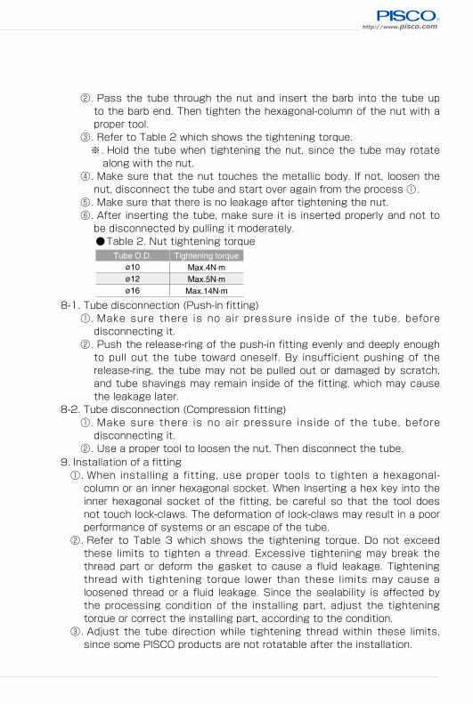
9. Installation of a fitting①. When installing a fitting, use proper tools to tighten a hexagonal-
column or an inner hexagonal socket. When inserting a hex key into theinner hexagonal socket of the fitting, be careful so that the tool doesnot touch lock-claws. The deformation of lock-claws may result in a poorperformance of systems or an escape of the tube.
②. Refer to Table 3 which shows the tightening torque. Do not exceedthese limits to tighten a thread. Excessive tightening may break thethread part or deform the gasket to cause a fluid leakage. Tighteningthread with tightening torque lower than these limits may cause aloosened thread or a fluid leakage. Since the sealability is affected bythe processing condition of the installing part, adjust the tighteningtorque or correct the installing part, according to the condition.
③. Adjust the tube direction while tightening thread within these limits,since some PISCO products are not rotatable after the installation.
②. Pass the tube through the nut and insert the barb into the tube upto the barb end. Then tighten the hexagonal-column of the nut with aproper tool.
③. Refer to Table 2 which shows the tightening torque.※. Hold the tube when tightening the nut, since the tube may rotate
along with the nut.④. Make sure that the nut touches the metallic body. If not, loosen the
nut, disconnect the tube and start over again from the process ①.⑤. Make sure that there is no leakage after tightening the nut.⑥. After inserting the tube, make sure it is inserted properly and not to
be disconnected by pulling it moderately.Table 2. Nut tightening torque
Tube O.D. Tightening torqueø10 Max.4N·mø12 Max.5N·mø16 Max.14N·m
8-1. Tube disconnection (Push-in fitting)①. Make sure there is no air pressure inside of the tube, before
disconnecting it.②. Push the release-ring of the push-in fitting evenly and deeply enough
to pull out the tube toward oneself. By insufficient pushing of therelease-ring, the tube may not be pulled out or damaged by scratch,and tube shavings may remain inside of the fitting, which may causethe leakage later.
8-2. Tube disconnection (Compression fitting)①. Make sure there is no air pressure inside of the tube, before
disconnecting it.②. Use a proper tool to loosen the nut. Then disconnect the tube.

真空発生器・真空ポンプ対応ユニット・真空パッド・真空関連機器SeriesIndexCommon Safety Instructions for Products Listed in This Manual
Table 3. Tightening torque / Sealock color / Gasket materialsThread type Thread size Tightening torque Sealock color Gasket material
Metric thread
M3×0.5 0.7N·m
n/a
SUS304+NBRSPCC+NBR
M5×0.8 1 ~ 1.5N·mM6×1 2 ~ 2.7N·m
M3×0.5 0.7N·m
POMM5×0.8 1 ~ 1.5N·mM6×0.75 0.8 ~ 1N·mM8×0.75 1 ~ 2N·m
Taper pipe thread
R1/8 4.5 ~ 6.5N·m
White R1/4 7 ~ 9N·mR3/8 12.5 ~ 14.5N·mR1/2 20 ~ 22N·m
Unified thread No.10-32UNF 1 ~ 1.5N·m n/a SUS304+NBR, SPCC+NBR
National Pipe Thread Taper
(American standard)
1/16-27NPT 4.5 ~ 6.5N·m
White 1/8-27NPT 4.5 ~ 6.5N·m1/4-18NPT 7 ~ 9N·m3/8-18NPT 12.5 ~ 14.5N·m1/2-14NPT 20 ~ 22N·m
G threadG1/4 12 ~ 14N·m
n/a Aluminum + PBTG3/8 22 ~ 24N·mG1/2 28 ~ 30N·m
※. These values may differ for some products. Refer to each specification as well.④. When removing a fitting, use proper tools to loosen a hexagonal-column
or an inner hexagonal socket. When inserting a hex key into the innerhexagonal socket of the fitting, be careful so that the tool does nottouch lock-claws. The deformation of lock-claws may result in a poorperformance of systems or an escape of the tube.
⑤. Remove the sealant stuck on the mating equipment. The remainedsealant may get into the peripheral equipment and cause malfunctions.
10. Handling of fitting①. Impact caused by dropping or the like may lead to damage to the
product and a fluid leakage.