CAD Integration Guidelines for Photon Beamline - European XFEL
European X-Ray Free-Electron Laser Facility GmbH
Albert-Einstein-Ring 19
22761 Hamburg
Germany
XFEL.EU TN-2013-005-02
TECHNICAL NOTE
Control System for the Photon Beamlines
July 2015
T. Korsch
for the X-Ray Optics and Beam Transport group (WP73)
at European XFEL

July 2015 XFEL.EU TN-2013-005-02 2 of 35 Technical Note: Control System for the Photon Beamlines
Contents
Revisions ..................................................................................................................... 4
Preface ......................................................................................................................... 5
1 Communication ................................................................................................. 6
1.1 PLC ........................................................................................................ 6 1.1.1 Bus terminals............................................................................. 6 1.1.2 Bus terminals for additional controller ....................................... 7
1.2 Operating parameters ............................................................................ 8 1.2.1 Vacuum pressure ...................................................................... 8 1.2.2 Cooling water flow ..................................................................... 8 1.2.3 Cooling water conductance ....................................................... 8 1.2.4 Compressed air ......................................................................... 8 1.2.5 Temperatures ............................................................................ 8 1.2.6 Beam shutter ............................................................................. 9 1.2.7 Valve ......................................................................................... 9 1.2.8 Motors ....................................................................................... 9
1.3 Software ................................................................................................. 9 1.3.1 PLC software ............................................................................. 9 1.3.2 GUI software ............................................................................. 9 1.3.3 GUI for a control system ......................................................... 10 1.3.4 Emergency system .................................................................. 10
1.4 Graphical user interface ....................................................................... 10 1.4.1 Symbols ................................................................................... 10 1.4.2 Buttons .................................................................................... 13 1.4.3 Service pages.......................................................................... 13 1.4.4 Log book .................................................................................. 14 1.4.5 Archive .................................................................................... 14 1.4.6 Automatic email ....................................................................... 14
2 Protection ......................................................................................................... 15
2.1 Safety during power failure .................................................................. 15 2.1.1 Power blackout ........................................................................ 15 2.1.2 Switch over .............................................................................. 15
2.2 Vacuum control and machine protection systems ............................... 15 2.2.1 Beam dump ............................................................................. 16 2.2.2 Machine stop ........................................................................... 17
2.3 Service work ......................................................................................... 17
3 Hardware .......................................................................................................... 18
3.1 PLC ...................................................................................................... 18 3.1.1 Bus coupler to controller ......................................................... 18 3.1.2 Bus terminals........................................................................... 18

XFEL.EU TN-2013-005-02 July 2015 Technical Note: Control System for the Photon Beamlines 3 of 35
3.2 PLC topology ........................................................................................ 19 3.3 Power concept ...................................................................................... 21
3.3.1 Power for bus coupler ............................................................. 21 3.3.2 Power for components ............................................................ 22
3.4 Connectors ........................................................................................... 22 3.4.1 Stepper motor.......................................................................... 22 3.4.2 Encoder ................................................................................... 22
3.5 Cable .................................................................................................... 23 3.5.1 Labels for cables ..................................................................... 24 3.5.2 Cable for valves ...................................................................... 25 3.5.3 Cable for ion pumps ................................................................ 25 3.5.4 Cable for sensor fast valve ...................................................... 25 3.5.5 Cable for temperature measurement ...................................... 25 3.5.6 Cable for creates / bus coupler ............................................... 26
4 PLC program logic .......................................................................................... 27
4.1 Global variables.................................................................................... 27 4.1.1 Global variables ...................................................................... 27 4.1.2 Main global .............................................................................. 27 4.1.3 Low global ............................................................................... 27
4.2 Main functions ...................................................................................... 27 4.2.1 PLC lock .................................................................................. 28
4.3 Logic functions for components ........................................................... 28 4.3.1 Logic for valves ....................................................................... 28 4.3.2 Ion pump controller ................................................................. 29 4.3.3 Experiments ............................................................................ 29 4.3.4 Fast valve ................................................................................ 30
A Abbreviations .................................................................................................. 31
B Cabling connection guidelines ...................................................................... 32
B.1 Cable for ion pumps ............................................................................. 32 B.1.1 Seven-part connector .............................................................. 32 B.1.2 Six-part connector ................................................................... 34
B.2 Pin array ............................................................................................... 35

July 2015 XFEL.EU TN-2013-005-02 4 of 35 Technical Note: Control System for the Photon Beamlines
Revisions
Version Date Description
1.1 23 Jul. 2015 Second release: Added all components with motion to the control systems Separated equipment protection from vacuum control
1.0 10 Dec. 2013 First release

XFEL.EU TN-2013-005-02 July 2015 Technical Note: Control System for the Photon Beamlines 5 of 35
Preface
In the European XFEL tunnel, X-ray light will be transported in beamlines
from the source point to the experiment. The main objective of the control
system for beam transport and optics is to enable the machine to run free of
imperfections in time for end-user operation.
The control system is divided into three subsystems: vacuum, motion, and
equipment protection.
The main goal of the vacuum control system is to take care of the vacuum in
the beamline and to protect the accelerator for vacuum.
The motion control system is for any movable device that is not vacuum-
related. For the optical characteristics of the light, monochromators, mirrors,
shutters, slit systems, apertures, and other parts will be installed. These
optical devces are typically movable in the beam. Motion control system
hardware and software is suitable for all electric or pneumatic moving parts
that are not relevant to vacuum.
The equipment protection control system is designed to ensure the secure
operation of the beam for the experiments. It takes care of correct water
cooling, air compression, and other supply media.

July 2015 XFEL.EU TN-2013-005-02 6 of 35 Technical Note: Control System for the Photon Beamlines
1 Communication
Communication in the context of the control system means the information
exchange between the PLC, bus coupler, and controller for components, as
well as the information that will be shown to the control person.
1.1 PLC The PLC will be a Beckhoff system with EtherCAT Bus. The system will be
built in a ring structure (see Figure 1) for each control part. The PLC is
outside the tunnel and connected to a bus coupler inside the tunnel. With an
optical fiber to decouple any grounding or shielding problems, the EtherCAT
signal is transferred to a patch panel in the electronic rack. The optical fiber is
a single-mode fiber. The signal will transfer from one coupler to the next
coupler on wire with a cable in RJ45 geometry if the distance is less than
100 m.
Figure 1: EtherCAT Terminals and PLC
1.1.1 Bus terminals
The bus coupler provides an EtherCAT line for different terminals. The
terminals read physical signals, switch voltage, open or close contacts, or
send and read data protocols.
Tunnel
EtherCAT – Rj45
Cable < 100 m
Master
PLC
LWL single-mode
Bus coupler

XFEL.EU TN-2013-005-02 July 2015 Technical Note: Control System for the Photon Beamlines 7 of 35
Figure 2: Bus coupler and terminals for different signals
Table 1: Function of the terminals
Function Type Low High Range Signal
Digital input ES1008 0 V 24 V — —
Digital output ES2008 0 V 24 V — —
Digital output (fast < 3 ms) ES2202 0 V 24 V — —
Analog input ES3164 — — 0–10 V —
ES3054 — — 4–20 mA —
Communication EL6002 — — — 2 x RS232
EL6022 — — — 2 x RS485
Temperature ES3314 — — — Type K
ES3202 — — — PT100
Relay output ES2624 4 x NO contacts
Bus coupler EK1101 EtherCAT coupler
EK1122 Two-port EtherCAT junction
EK1501-0010 EtherCAT coupler for single mode fibre junction
EK1521-0010 One-port EtherCAT fibre optic junction
1.1.2 Bus terminals for additional controller
The control system and its terminals provide a lot of communication protocols,
such as RS232, RS485, and RS422.
RS485 communication is used for the following:
Ion pump controller (Agilent Technologies, Type 4UHV Ion Pump
Controller)
Turbo pump controller (Pfeiffer TCP 350)
Limit switch
Vacuum pressure
Pump controller
Digital
Analog
RS485
Bus
coupler
with
terminals

July 2015 XFEL.EU TN-2013-005-02 8 of 35 Technical Note: Control System for the Photon Beamlines
1.2 Operating parameters
1.2.1 Vacuum pressure
The ion pump controller is from Agilent, Type 4 UHV, with a negative high
voltage of up to 7 kV. There are two types of controllers: one can provide four
pumps with 80 W (Model 9299400); the other can control two pumps with
200 W (Model 9299020). The current for an ion pump is in relation to the
vacuum pressure, so the information about the vacuum can be read out by
the controller for the ion pumps. The controller provides the standard RS485
protocol and a threshold for an adjustable vacuum pressure. With a wire
connection between the controller and the terminals, the PLC can read the
vacuum pressure information and alarms. The vacuum pressure is read out
via RS485, and alarm signals are read out by the contact threshold in the
controller to digital input terminals.
1.2.2 Cooling water flow
With additional boxes, the flow rate can be measured. The box gives a
4–20 mA signal according to the flow.
The cooling water is also measured with a temperature switch. If the
temperature is too high, a contact will open.
1.2.3 Cooling water conductance
The conductance is measured in the cooling water.
1.2.4 Compressed air
The compressed air is measured with a pressure device. The box gives a
4–20 mA signal according to the pressure. For some devices, a sensor with a
simple switchpoint opens an electrical contact if the pressure is below the set
value. Minimimum compressed air will be measured in every tunnel.
1.2.5 Temperatures
For temperatures, a PT 100 (platinum with a resistor of 100 Ω by 0°C) should
be used. Only in some special cases is a thermocouple Type K allowed.
XFEL.EU TN-2013-005-02 July 2015 Technical Note: Control System for the Photon Beamlines 9 of 35
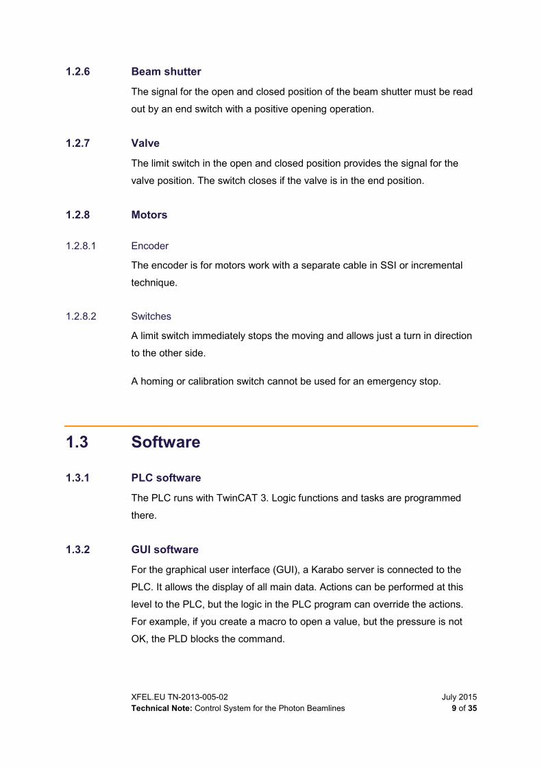
1.2.6 Beam shutter
The signal for the open and closed position of the beam shutter must be read
out by an end switch with a positive opening operation.
1.2.7 Valve
The limit switch in the open and closed position provides the signal for the
valve position. The switch closes if the valve is in the end position.
1.2.8 Motors
1.2.8.1 Encoder
The encoder is for motors work with a separate cable in SSI or incremental
technique.
1.2.8.2 Switches
A limit switch immediately stops the moving and allows just a turn in direction
to the other side.
A homing or calibration switch cannot be used for an emergency stop.
1.3 Software
1.3.1 PLC software
The PLC runs with TwinCAT 3. Logic functions and tasks are programmed
there.
1.3.2 GUI software
For the graphical user interface (GUI), a Karabo server is connected to the
PLC. It allows the display of all main data. Actions can be performed at this
level to the PLC, but the logic in the PLC program can override the actions.
For example, if you create a macro to open a value, but the pressure is not
OK, the PLD blocks the command.

July 2015 XFEL.EU TN-2013-005-02 10 of 35 Technical Note: Control System for the Photon Beamlines
Figure 3: GUI for the interlock
1.3.3 GUI for a control system
The GUI is based on Karabo software. User operations are split into five
levels of access rights: Admin, Expert, Operator, User, and Observer.
1.3.4 Emergency system
For the main tasks, a display is directly connected to the PLC. It allows a
simple diagnostic for the complete system and control components without
any network.
1.4 Graphical user interface The main goal of a good GUI is provide an intuitional use and understanding
of the system. Without a lot of explantion, the GUI must provide a simple way
to open and close valves without any risk. The GUI is defined in the “XFEL
User Interface Style Guide”:
https://xfel-wiki.desy.de/XFEL_User_Interface_Style_Guide
1.4.1 Symbols
Symbols for components are based on the International Electrotechnical
Commission “Graphical Symbols for Use on Equipment” (IEC 60417) and the
European Committee for Electrotechnical Standardization “Safety of
Master
PLC
Karabo
server
PC
PC
PC
Display
Network USB,DVI

XFEL.EU TN-2013-005-02 July 2015 Technical Note: Control System for the Photon Beamlines 11 of 35
Machinery – Electrical Equipment of Machines – Part 1: General
Requirements” (EN 60204-1:2006).
In addition, the following symbols are used:
Beamline
Single solid line in black (Figure 4).
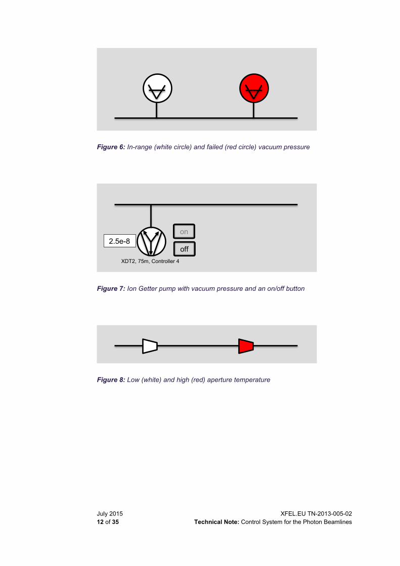
Aperture
Isosceles triangle with the small side to the experiment side (Figure 8). If
there is a temperature alarm, it switches from white to red. The small side
is half the length of the side. The inner angle is 70° and 120°.
Figure 4: Beamline
Figure 5: Open (vertical back line) and closed (vertical red line) valve
July 2015 XFEL.EU TN-2013-005-02 12 of 35 Technical Note: Control System for the Photon Beamlines
Figure 6: In-range (white circle) and failed (red circle) vacuum pressure
Figure 7: Ion Getter pump with vacuum pressure and an on/off button
Figure 8: Low (white) and high (red) aperture temperature
2.5e-8 off
on
XDT2, 75m, Controller 4

XFEL.EU TN-2013-005-02 July 2015 Technical Note: Control System for the Photon Beamlines 13 of 35
Figure 9: GUI for the vacuum interlock at the PETRA III beamline
1.4.2 Buttons
Buttons are visible in different rules to the user. For experts, all buttons are
visible. For guests, no buttons are visible.
Buttons are visible only if the user role enables the user to switch them. The
caption of a button is black or grey if it cannot be used or is out of order. A
single button can have only one function. That is, there are two buttons for
any given valve: one for open and one for closed. A single button cannot
switch between open and closed.
1.4.3 Service pages
A service page is useful for a quick and efficient search for problems. This
page includes all backup information, all hidden properties, and a log book.
The service page shows information such as cooling water, compressed air,
hardware status, power supplies status, counter for valves, and so on.
July 2015 XFEL.EU TN-2013-005-02 14 of 35 Technical Note: Control System for the Photon Beamlines
1.4.4 Log book
All activities on the PLC must be logged with a time stamp and shown in a
text field. Every action is logged in text format (without any special characters
or symbols): “component, action, time”. The component defines kind and
place. The action is the change of the component. The time is defined as
year, month, day, hour, minute, and second in the format
YYYY.MM.DD.hh.mm.ss (e.g. Valve V3102, closed, 2015.03.12.13.43.21).
1.4.5 Archive
Some data will be saved for several years with a low frequency.
The following data must be stored 10 times a minute:
Vacuum pressure, readout of the controller
Cooling water temperature
Compressed air
Configuration of each ion pump controller
1.4.6 Automatic email
For some tasks, an automatically generated email will be sent. For minor
tasks, an SMS will be sent.

XFEL.EU TN-2013-005-02 July 2015 Technical Note: Control System for the Photon Beamlines 15 of 35
2 Protection
For all control systems, faultless operation of the system is essential. Any
minor fault, which can stop the machine, causes a delay in the experiments.
Any major fault must be protected by hardware and software components.
2.1 Safety during power failure
2.1.1 Power blackout
Power failure means a complete disruption of the supply voltage in the whole
system, or a failure in one unit without a bridge to the redundancy module. If a
power failure occurs, the system must switch to Save status.
In Save status, the following occurs:
All valves close without power connection.
Machines dump to protect the valves.
2.1.2 Switch over
If the mains voltages switch off for less than 100 ms the System must run
without a failure. For this kind of power failure, each power supply bridges a
gap of 30 ms. This provides the section of the beamline with power, using a
redundancy system in which each power supply runs with a normal load of
50% total operating performance.
2.2 Vacuum control and machine protection systems The machine protection system (MPS) is the process used to maintain the
safety of the accelerator and to shut down and stop the system, if needed.

July 2015 XFEL.EU TN-2013-005-02 16 of 35 Technical Note: Control System for the Photon Beamlines
The vacuum control system is responsible stopping the accelerator if
something happens that threatens the safety of the controlled beamlines. The
shutdown will activate with a change of one bit via the RS422 protocol.
Figure 10: Communication between vacuum PLC and MPS
2.2.1 Beam dump
In some cases, the accelerator must be pumped to protect the beamline and
its components.
These cases are:
Tripping of a fast shutting valve.
Unexpected non-opening of a valve. In this case, the activator is active,
and the open end switch is lost.
In each of these cases, an alarm is sent to the user. The alarm indicates
which case produced the shutdown.

XFEL.EU TN-2013-005-02 July 2015 Technical Note: Control System for the Photon Beamlines 17 of 35
2.2.1.1 Hardware for beam dump
The machine shutdown is possible on a separate RS422 line. The beam
dump will activate with a change of one bit via the RS422 protocol.
Two elements are directly connected to this line:
Fast valve
The control unit for a fast shutting valve is directly connected to this line.
Software identification of a failure
The PLC shutdown will switch on separate Beckhoff ES2202 terminals
with a fast output of < 1 μs.
2.2.2 Machine stop
The accelerator must stop to protect the beamline and its components in the
following cases:
Temperature alarm
Cooling water flow
Failure of a global variable (see Section 2.1, “Safety during power failure”,
on page 15)
Valve closed by PLC
Hardware failure
— A power supply is not working.
— No compressed air.
2.3 Service work For service or repair of components in the tunnel that are controlled by the
PLC, a safety key can be removed from the panel at the control station.
Without this key, the PLC does not allow movement of any device. The PLC
indicates that the key is missing. Workers are responsible for their own work
and safety.

July 2015 XFEL.EU TN-2013-005-02 18 of 35 Technical Note: Control System for the Photon Beamlines
3 Hardware
The hardware of the PLC, bus coupler, terminals, and power supply is defined
in this chapter. The systems with PLC, bus coupler, and bus terminals use a
modular technique. In this modular structure, the interpolation of new
components can be done quickly and easily.
3.1 PLC For the control system, the Advanced Electronics group will program the PLC.
In most of the systems, a Beckhoff PLC with EtherCAT protocol is to be used.
3.1.1 Bus coupler to controller The bus coupler and additional terminals provide a lot of communication
protocols, such as BiSS-C, RS232, RS485, and RS422.
3.1.2 Bus terminals The bus coupler provides an EtherCAT line for different terminals. The
terminals read physical signals, switch voltage, or send and read data
protocols.
Table 2: Function of the terminals
Function Type Low High Range Signal
Digital input ES1008 0 V 24 V — —
Digital output ES2008 0 V 24 V — —
Analog input ES3164 — — 0–10 V —
ES3054 — — 4–20 mA —
Communication EL6002 — — — RS232
EL6022 — — — RS485
Stepper motor ES 7041 — — — —
SinCos encoder ES 5021 — — — —
Temperature ES3314 — — — Type K
ES3202 — — — PT100
Bus coupler EK1122 Two-port EtherCAT junction EK1521 One-port EtherCAT fibre optic junction
RS 485 EL6022 2-channel serial interfaces RS485, D-sub connection

XFEL.EU TN-2013-005-02 July 2015 Technical Note: Control System for the Photon Beamlines 19 of 35
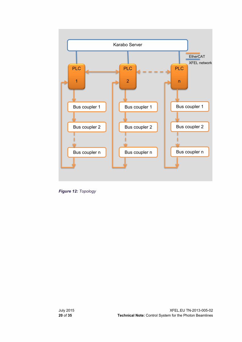
3.2 PLC topology For each SASE tunnel, one PLC each is responsible for the vacuum, motion,
and equipment protection control systems. For example, SASE 1 has three
PLCs, and these PLCs controls Experiments 10–12.
Figure 11: SASE tunnel definition
All PLCs work in the same hierarchy without a master PLC. They
communicate via EtherCAT with each other and each PLC in the Karabo
system.
July 2015 XFEL.EU TN-2013-005-02 20 of 35 Technical Note: Control System for the Photon Beamlines
Figure 12: Topology
Karabo Server
Bus coupler n
Bus coupler 2
Bus coupler 1
Bus coupler n
Bus coupler 2
Bus coupler 1
PLC
1
PLC
2
PLC
n
Bus coupler n
Bus coupler 2
Bus coupler 1
EtherCAT
XFEL network

XFEL.EU TN-2013-005-02 July 2015 Technical Note: Control System for the Photon Beamlines 21 of 35
Figure 13: Signal communication
3.3 Power concept The system works with 24 V DC. Other voltages must be provided with
different power supplies and need extra terminals. 24 V are also provided for
the components. The 24 V circuit is protected with a glass fuse. The power
supply is protected against short circuits and overloads. All wires must
connect to the terminals without screws; only spring terminals are allowed.
If another voltage is required (e.g. 12 V), a separate power supply can be
requested from the X-Ray Optics and Beam Transport group.
3.3.1 Power for bus coupler
For each bus coupler in the tunnel, there are two power supplies with a power
balance module that provides the 24 V. The two power supplies are on
different phases (L1, L2) and get their own fuse. The power supplies and the
balance module have alarm contacts for temperature and overcurrent, which
are read out.
PLC 1
MPS RS 422
Switch contacts EtherCAT
Bus coupler Fast valve
controller
July 2015 XFEL.EU TN-2013-005-02 22 of 35 Technical Note: Control System for the Photon Beamlines
3.3.2 Power for components
The components for the vacuum interlock, such as actuators for valves, end
switches, gauges, and so on are served by the power supply of the bus
coupler.
3.4 Connectors The list of connectors is defined by the Advanced Electronics group.
Components in the tunnel are hard installations. On the PLC side, no
connector is provided. A patchboard is at the device and not at the electronic
rack. Cables are fixed at one end on the PLC terminals and attached at the
other end to the patchboard at the component.
3.4.1 Stepper motor
For the stepper motor, LEMO Type 3B is defined with 8 pins and the key
system G. Limit switches are “normally closed” contacts. For more information
about the pin array, see Section B.2, “Pin array”.
3.4.2 Encoder
For the encoder, Lemo Type 1B is defined with 8 pins and the key system C.
For more information about the pin array, see Section B.2, “Pin array”

XFEL.EU TN-2013-005-02 July 2015 Technical Note: Control System for the Photon Beamlines 23 of 35
3.5 Cable For cable inside the tunnel, the DESY specifications are obligatory.
Name: “Technische Spezifikation Energieversorgung Nr. 13/2005 über
brandschutztechnische Anforderungen an halogenfreie und flammwidrige
Kabel und Leitungen in den Anlagen von DESY”
The respective DIN VDE 0100 references apply.
Connections to cable cores to crimp are always preferred before screwing
and before soldering.

July 2015 XFEL.EU TN-2013-005-02 24 of 35 Technical Note: Control System for the Photon Beamlines
3.5.1 Labels for cables
One side of the cable includes a label with the distance in the tunnel in
metres. The other side includes the rack number.
Table 3: Label system for cables
Letter / Number L N N NN N L
Sample V 1 0 15 0 G
Component type • Gauge
– C = Cold cathode – F = Full range – P = Pirani – S = Spinning rotor
• Pump – I = Ion P. – M = Membran P. – N = NEG P. – R = Rootsp. – S = Scroll P. – T = Turbo P.
• Valve – A = Angel V. – D = Dosing V. – F = Fast V. – G = Gate V. – M = All Metal V. – V = Vatterfly V.
Future upgrades Strart 0..9
Component counter Two numbers 00..99
Beamline zone • 0 = From hand-over point with WP19 up to separation
chamber • 1 = Center • 2 = Left • 3 = Right
Beamline number • 1 = SASE 1 • 2 = SASE 2 • 3 = SASE 3
Component category • G = Gauge • P = Pump • V = Valve

XFEL.EU TN-2013-005-02 July 2015 Technical Note: Control System for the Photon Beamlines 25 of 35
3.5.2 Cable for valves
For a valve, a cable with 5 cores with a M12 connector (female straight) is
available for use. On the PLC side, this cable is directly connected to the
terminals. On the other side, it has a connector.
3.5.3 Cable for ion pumps
For the cable from the ion pumps to the high voltage controller, a cable of the
following type should be used:
DESY HV-CABLE 0.9/3.2 + 1x0.35mm² - DRAKA – yyyy – ZERO HALOGEN 09 3211173 207171642 nnn m
Where “yyyy” is the year of manufacturing and “nnn” is the lineal meter. This
cable type includes a core for high voltage that is shielded and a second core
for the interlock connection. For detailed information about this cable, see
Appendix B.1, “Cable for ion pumps”.
3.5.4 Cable for sensor fast valve
The cable for the senor fast valve is similar to the cable for ion pumps. The
only difference is that a different connector is used.
3.5.5 Cable for temperature measurement
For a temperature measurement with PT 100, a three-core cable should be
used.
Figure 14: Temperature measurement with PT100 in a three-port cable
For thermocouple Type K, a cable of IEC standard must be used, with green
coat, red (+), and white (-) isolation.
July 2015 XFEL.EU TN-2013-005-02 26 of 35 Technical Note: Control System for the Photon Beamlines
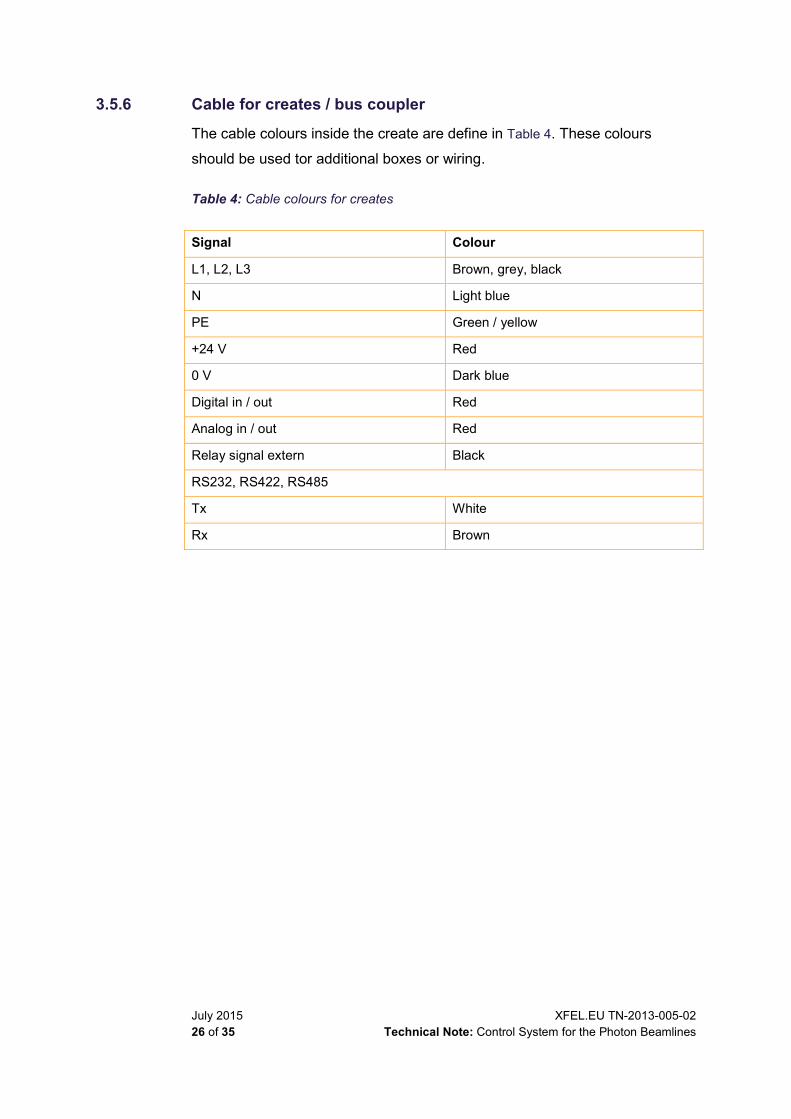
3.5.6 Cable for creates / bus coupler
The cable colours inside the create are define in Table 4. These colours
should be used tor additional boxes or wiring.
Table 4: Cable colours for creates
Signal Colour
L1, L2, L3 Brown, grey, black
N Light blue
PE Green / yellow
+24 V Red
0 V Dark blue
Digital in / out Red
Analog in / out Red
Relay signal extern Black
RS232, RS422, RS485
Tx White
Rx Brown
XFEL.EU TN-2013-005-02 July 2015 Technical Note: Control System for the Photon Beamlines 27 of 35
4 PLC program logic
The various parts of essential PCL program logic are described in this
chapter.
4.1 Global variables In general, some variables must be provided.
4.1.1 Global variables
Machine status: shut down / run
Beamshutter: open / close
4.1.2 Main global
Compressed air: n.n bar
Cooling water flow: nnn l/h
Temperatures in range: nn°C
4.1.3 Low global
Power supply for each bus coupler: operate and temperature in range
Vacuum pressure for each pump: n.n e–n mbar
Valve position: open / closed
4.2 Main functions This section describes the main functions.

July 2015 XFEL.EU TN-2013-005-02 28 of 35 Technical Note: Control System for the Photon Beamlines
4.2.1 PLC lock
In accordance with EN60204-1: For safe work at a component or part of a
system, it is necessary to switch off the system and get a status that no
moving parts can be dangerous to people.
This lock closes all valves and beam shutters, and prevents them from re-
opening even if someone attempts to switch from the GUI. If the lock is re-
locked, all valves and beam shutters must opened by hand in the GUI
Figure 15: Key–lock layout for the PLCs
4.3 Logic functions for components
4.3.1 Logic for valves
Valves are normally open.
They close when one of the following conditions (failures) occurs:
Vacuum pump fails in a section
Global variable fails in the section
User can close a valve by clicking a button in the GUI
PLC
SASE 1
PLC
SASE 2
PLC
SASE 3
PLC
SASE 4
PLC
SASE 5
TO LOCK UNPLUG THE KEY
XFEL.EU TN-2013-005-02 July 2015 Technical Note: Control System for the Photon Beamlines 29 of 35
Activator is active but the open end switch is not active after three
seconds
A valve can close only when the beam shutter is closed before the valve. If
one pump controller fails for ≤ 3 seconds, the valves does not close the
section.
The open and closed cycles are counted for each valve.
Valves can be opened when:
Vacuum pressure on both sides of the valve is in range.
The open and closed positions are registered with end switches. If both end
switches are not active for more than three seconds, the PLC must create an
alarm.
4.3.2 Ion pump controller
The ion pump controller can be switched on and off by clicking in the GUI.
Switching off is possible only when the valve has closed the section.
Switching on is possible in expert mode
The ion pump controller provides the vacuum pressure information of the
pump. A operation time counter have to run for each pump and for the
controller.
The configuration for connected pumps, set points, alarms, and steps of fixed
voltage must be adjusted, saved to the archive, loaded to the controller, and
backed up to the Karabo server. The information can then be loaded onto
new controllers, overriding their standard configurations.
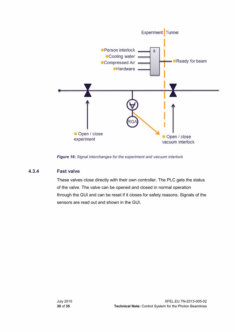
4.3.3 Experiments
For all experiments, an ion pump on the side of the experiment is necessary
to make sure the vacuum pressure is adequate to open a valve.
July 2015 XFEL.EU TN-2013-005-02 30 of 35 Technical Note: Control System for the Photon Beamlines
Figure 16: Signal interchanges for the experiment and vacuum interlock
4.3.4 Fast valve
These valves close directly with their own controller. The PLC gets the status
of the valve. The valve can be opened and closed in normal operation
through the GUI and can be reset if it closes for safety reasons. Signals of the
sensors are read out and shown in the GUI.
XFEL.EU TN-2013-005-02 July 2015 Technical Note: Control System for the Photon Beamlines 31 of 35
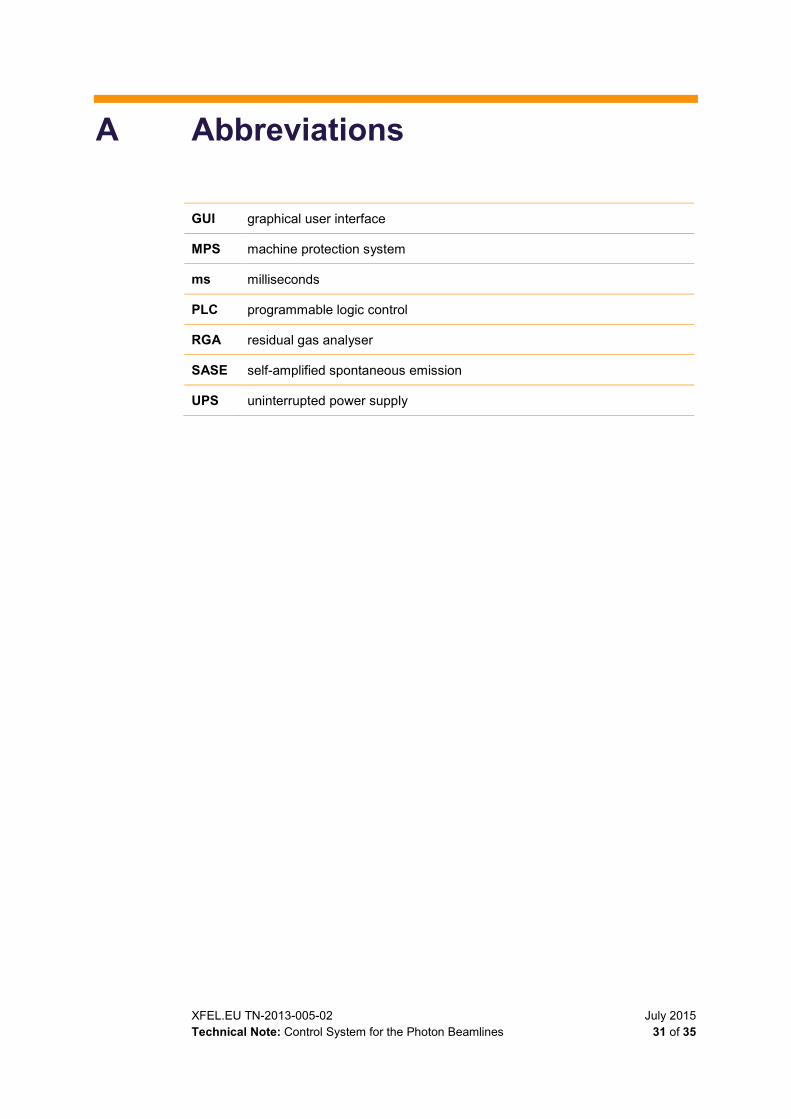
A Abbreviations
GUI graphical user interface
MPS machine protection system
ms milliseconds
PLC programmable logic control
RGA residual gas analyser
SASE self-amplified spontaneous emission
UPS uninterrupted power supply
July 2015 XFEL.EU TN-2013-005-02 32 of 35 Technical Note: Control System for the Photon Beamlines
B Cabling connection guidelines
B.1 Cable for ion pumps
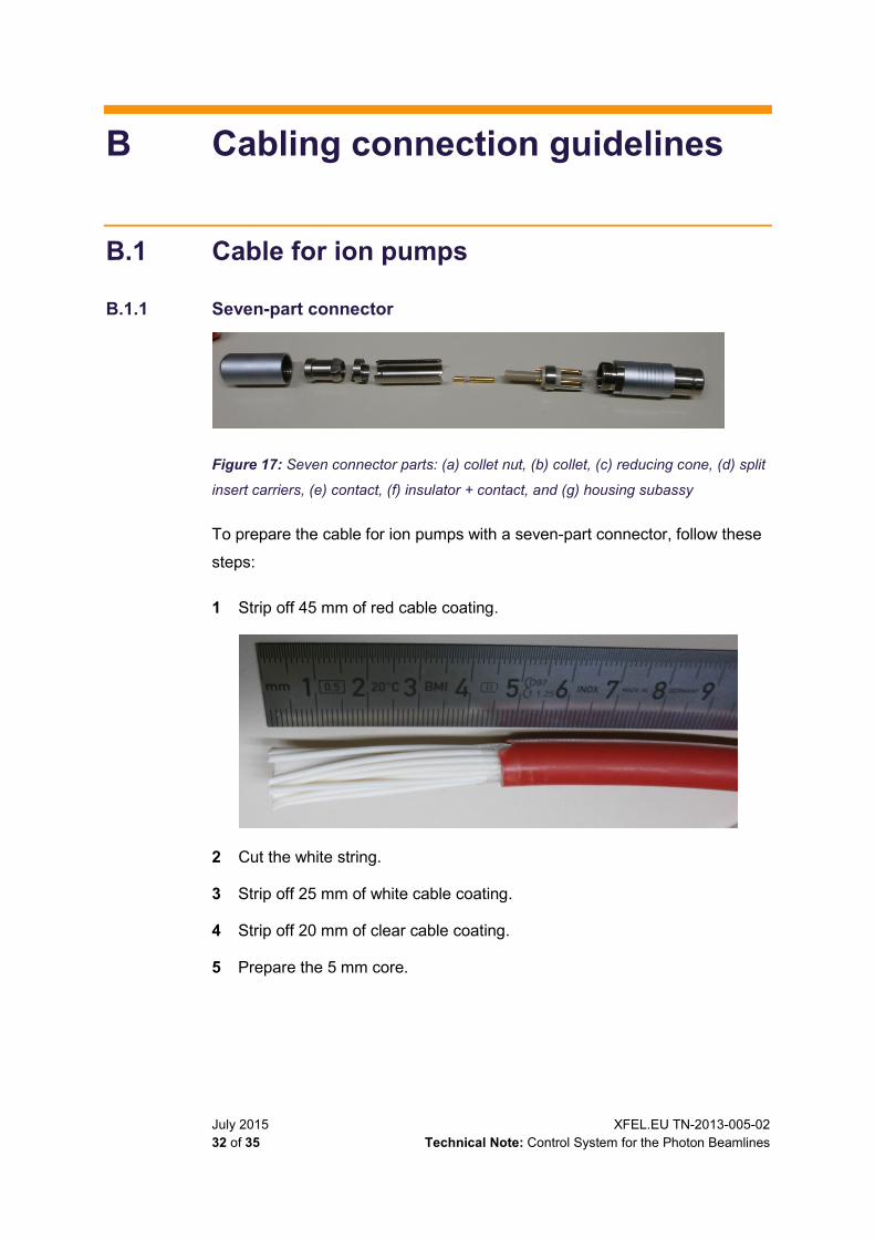
B.1.1 Seven-part connector
Figure 17: Seven connector parts: (a) collet nut, (b) collet, (c) reducing cone, (d) split
insert carriers, (e) contact, (f) insulator + contact, and (g) housing subassy
To prepare the cable for ion pumps with a seven-part connector, follow these
steps:
1 Strip off 45 mm of red cable coating.
2 Cut the white string.
3 Strip off 25 mm of white cable coating.
4 Strip off 20 mm of clear cable coating.
5 Prepare the 5 mm core.
XFEL.EU TN-2013-005-02 July 2015 Technical Note: Control System for the Photon Beamlines 33 of 35
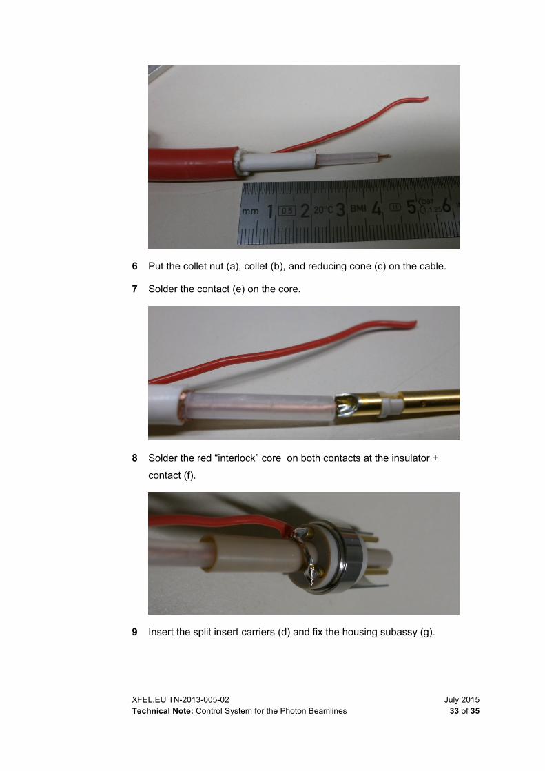
6 Put the collet nut (a), collet (b), and reducing cone (c) on the cable.
7 Solder the contact (e) on the core.
8 Solder the red “interlock” core on both contacts at the insulator +
contact (f).
9 Insert the split insert carriers (d) and fix the housing subassy (g).
July 2015 XFEL.EU TN-2013-005-02 34 of 35 Technical Note: Control System for the Photon Beamlines
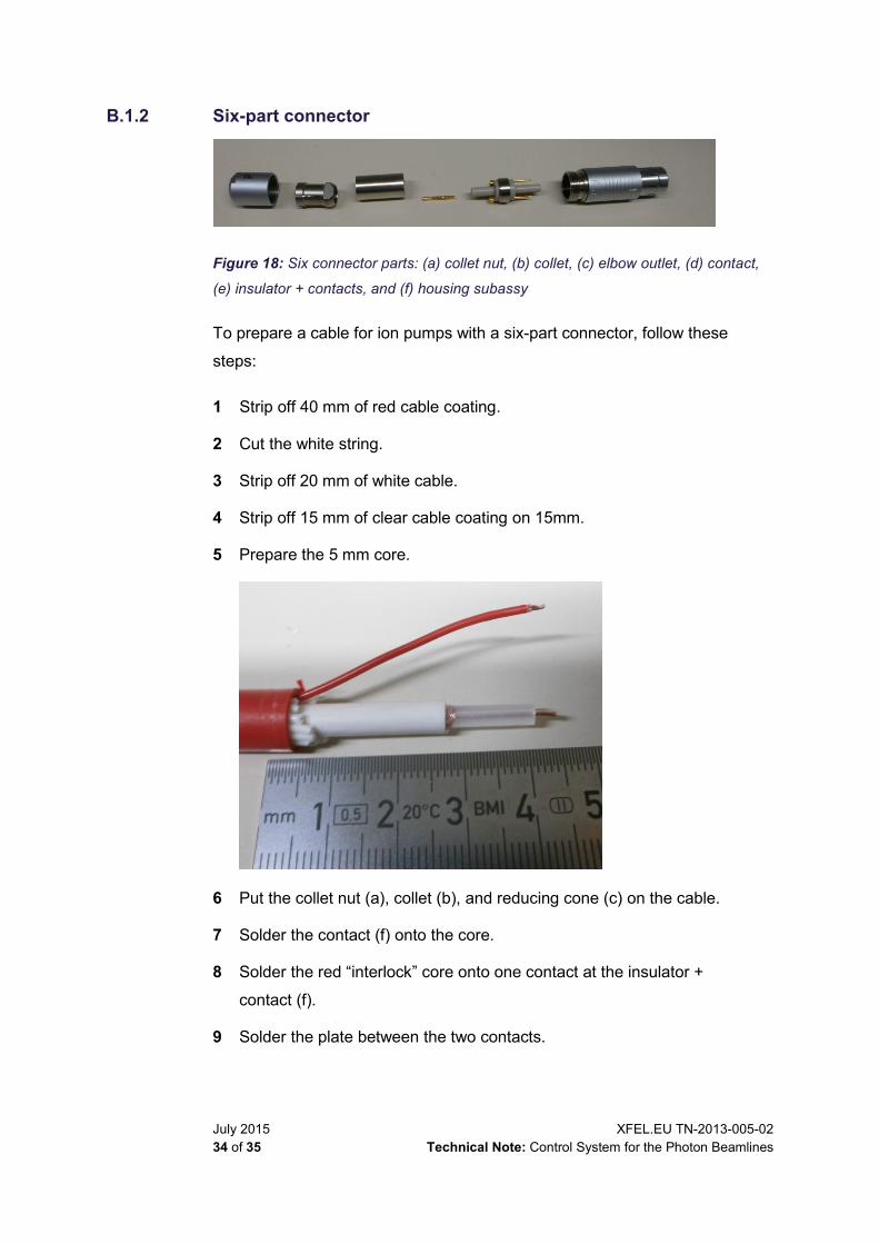
B.1.2 Six-part connector
Figure 18: Six connector parts: (a) collet nut, (b) collet, (c) elbow outlet, (d) contact,
(e) insulator + contacts, and (f) housing subassy
To prepare a cable for ion pumps with a six-part connector, follow these
steps:
1 Strip off 40 mm of red cable coating.
2 Cut the white string.
3 Strip off 20 mm of white cable.
4 Strip off 15 mm of clear cable coating on 15mm.
5 Prepare the 5 mm core.
6 Put the collet nut (a), collet (b), and reducing cone (c) on the cable.
7 Solder the contact (f) onto the core.
8 Solder the red “interlock” core onto one contact at the insulator +
contact (f).
9 Solder the plate between the two contacts.

XFEL.EU TN-2013-005-02 July 2015 Technical Note: Control System for the Photon Beamlines 35 of 35
10 Fix the housing subassy(g).
B.2 Pin array Table 5: Connectors use for stepper motors and encoders
Pin array Pin Motor Encoder Encoder SSI
1 2 3 4 5 6 7 8
A1 A2 GND Ub+ B1 B2 CW Limit CCW Limit
A+ A- B+ B- I+ I- Ub+ GND
D+ D- C+ C- DIR STAT V+ GND